Panasonic of North America 9TGWW11A TD-CDMA PCI Express Mini Module User Manual Module Integration guide
Panasonic Corporation of North America TD-CDMA PCI Express Mini Module Module Integration guide
Contents
- 1. User manual - host
- 2. Module Integration guide
- 3. Host User Manual
- 4. Users Manual
Module Integration guide

OEM PCI Express Mini Module Integration
OEM PCI Express Mini Module
Integration Guide
V01.02
4th March 2009 IPWireless Proprietary and Confidential Page 1 of 10
Subject to Non Disclosure Agreement

OEM PCI Express Mini Module Integration
4th March 2009 IPWireless Proprietary and Confidential Page 2 of 10
Subject to Non Disclosure Agreement
Contents
1General ................................................................................................................ 3
1.1Approvals and Dates ............................................................................................................... 3
1.2Change Record ....................................................................................................................... 3
1.3Acronyms ................................................................................................................................ 4
1.4External References ................................................................................................................ 4
2Introduction .......................................................................................................... 5
2.1Scope of Document ................................................................................................................. 5
2.2Overview of Module ................................................................................................................ 5
3Module Connections ............................................................................................ 6
3.1PCI Express Mini Interface (J1) .............................................................................................. 6
3.1.1Universal Serial Bus ........................................................................................................ 6
3.1.2SIM Interface ................................................................................................................... 6
3.2Media Independent Interface (J4) ........................................................................................... 6
3.3RF Connections ...................................................................................................................... 7
3.4DC Power ................................................................................................................................ 7
4Mechanical .......................................................................................................... 8
4.1Thermal Management ............................................................................................................. 8
5Regulatory Information ........................................................................................ 9
5.1Compliance with FCC Rules and Regulations ........................................................................ 9
5.2Exposure to Radio Frequency Signals .................................................................................... 9
6Annex 1: PCI Express Mini Edge Connector Pinout .......................................... 10
Figures
Figure 1: MII Interface J4 ........................................................................................................................ 6
Figure 2: RF Connections ....................................................................................................................... 7
Figure 3: PEM Module ............................................................................................................................ 8
OEM PCI Express Mini Module Integration
4th March 2009 IPWireless Proprietary and Confidential Page 3 of 10
Subject to Non Disclosure Agreement
1 General
1.1 Approvals and Dates
Approval Date
W. J. Jones
1.2 Change Record
Date Version Author Reason For Change Issue
20/08/2008 01.00 PFW New Document.
23/10/2008 01.01 PFW Additional details added.
04/03/2009 01.02 PFW Updated PEM Mechanical drawing.

OEM PCI Express Mini Module Integration
4th March 2009 IPWireless Proprietary and Confidential Page 4 of 10
Subject to Non Disclosure Agreement
1.3 Acronyms
Term Definition
MPE Maximum Permissible Exposure
OEM Original Equipment Manufacturer
PCIe PCI Express
PCI SIG PCI Special Interest Group
PEM PCI Express Mini
SIM Subscriber Identity Module
TDD Time Division Duplex
UMTS Universal Mobile Telephone System
USB Universal Serial Bus
1.4 External References
Ref
() Number Title
1 FCC Part 27 Miscellaneous Wireless Communications Service
2 PCI SIG PCI Express Base Specification Revision 2.0
3 PCI SIG Card Electromechanical Specification Revision 2.0
4 - PEM + Adapter Thermal Specification Revision 1.0
Note: Where a reference is undated, the latest version applies unless a specific revision is defined.

OEM PCI Express Mini Module Integration
4th March 2009 IPWireless Proprietary and Confidential Page 5 of 10
Subject to Non Disclosure Agreement
2 Introduction
This document describes the method of integrating the IPWireless PCI Express Mini module into an
OEM product.
2.1 Scope of Document
This document applies to the IPWireless PCI Express Mini module only.
2.2 Overview of Module
The IPWireless PCI Express Mini module provides a complete UMTS TDD wireless modem solution
and only requires to be inserted in a PCI Express Mini compliant interface and connection of external
antennas. The module is designed to minimise the time and resource required to integrate.
OEM PCI Express Mini Module Integration
3 Module Connections
3.1 PCI Express Mini Interface (J1)
The IPWireless PCI Express Mini module is provided with a 52 pin edge connector for connection to
the external application. This connection supports the following interface types and these are
described below. The pinout is shown in Annex 1.
3.1.1 Universal Serial Bus
The PCI Express edge connector provides a USB 2.0 interface, this interface supports low speed
(1.5Mbps), full speed (12Mbps) and High speed (480Mbps) operation.
3.1.2 SIM Interface
The PCI Express edge connector provides a 4 line SIM interface to allow use with Subscriber Identity
Modules if required, this interface supports both 1.8V and 3.0V SIM’s. The SIM interface does not
provide ESD protection and this should be provided by the host device.
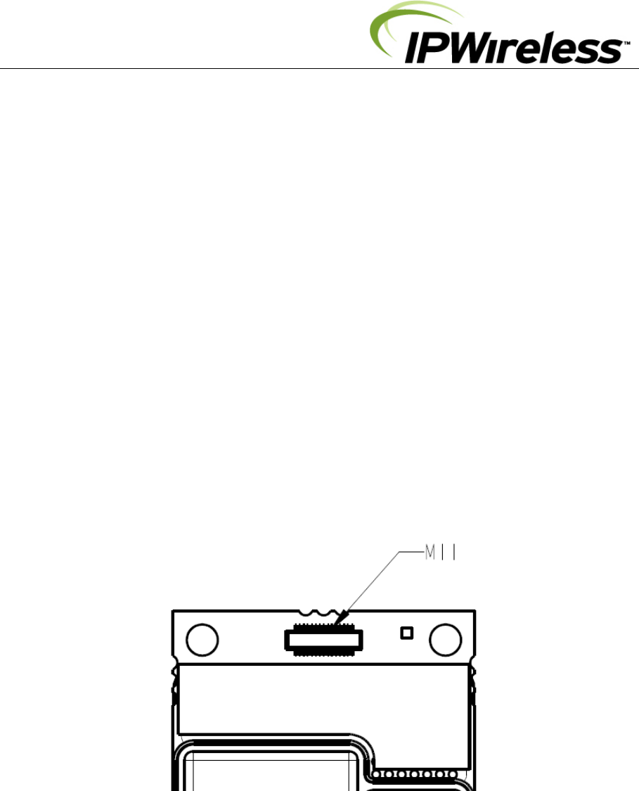
3.2 Media Independent Interface (J4)
The IPWireless PCI Express Mini module also provides a Media Independent Interface, this is a
separate interface and is used only with the IPWireless PEM Adapter Board.
Figure 1: MII Interface J4
4th March 2009 IPWireless Proprietary and Confidential Page 6 of 10
Subject to Non Disclosure Agreement
OEM PCI Express Mini Module Integration
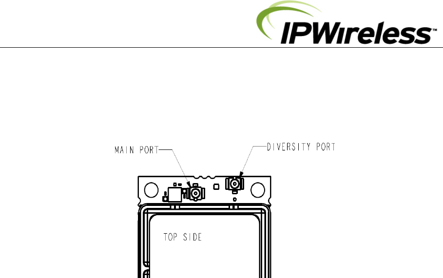
3.3 RF Connections
The IPWireless PCI Express Mini module provides two RF connections for external antennas. The
main port must be connected, the diversity port may or may not be connected depending upon
application. The connector type is the Hirose U.FL series.
Figure 2: RF Connections
3.4 DC Power
The module requires a DC supply of between 3.0V to 3.6VDC with the nominal voltage being
3.3VDC, maximum input current is 950mA at 3.3VDC. DC power is applied to the module via the PCI
Express Mini edge connector.
4th March 2009 IPWireless Proprietary and Confidential Page 7 of 10
Subject to Non Disclosure Agreement
OEM PCI Express Mini Module Integration
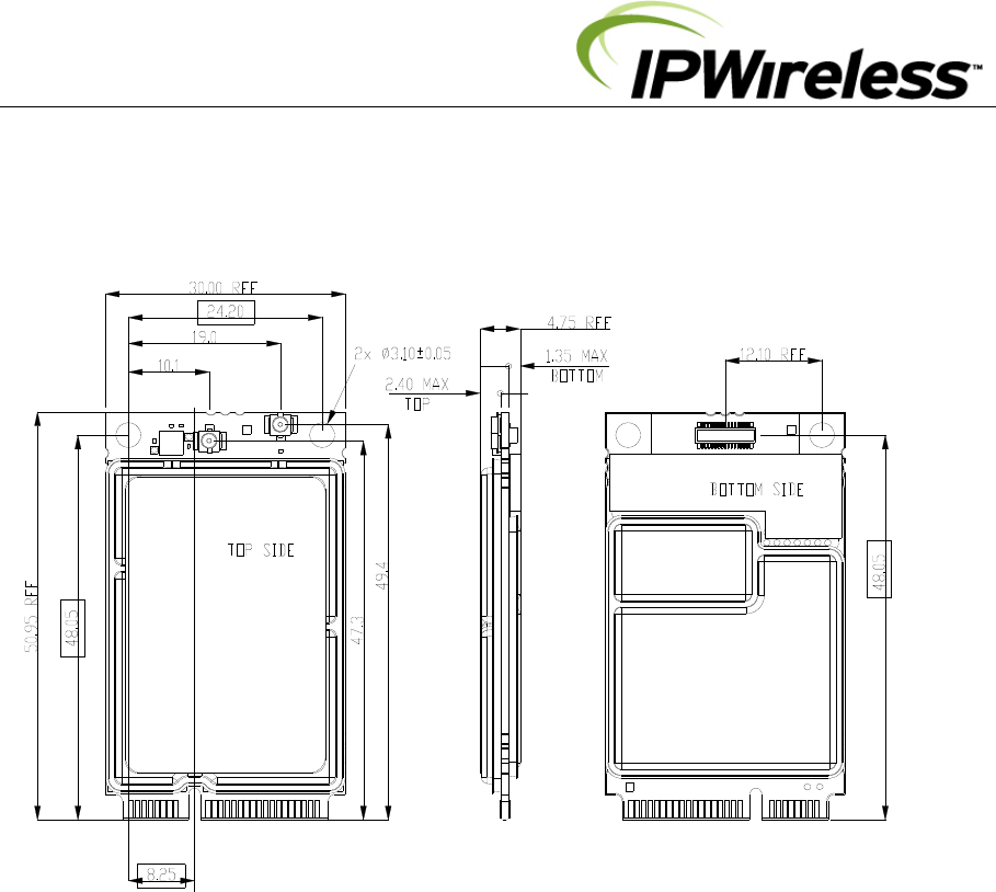
4 Mechanical
The IPWireless PCI Express Mini module is designed to be installed in a PCI Express compliant slot
capable of holding an F1 full size mini card.
Figure 3: PEM Module
4.1 Thermal Management
The PCI Express Mini module integration shall be in accordance with the PCISIG thermal
requirements.
4th March 2009 IPWireless Proprietary and Confidential Page 8 of 10
Subject to Non Disclosure Agreement

OEM PCI Express Mini Module Integration
4th March 2009 IPWireless Proprietary and Confidential Page 9 of 10
Subject to Non Disclosure Agreement
5 Regulatory Information
5.1 Compliance with FCC Rules and Regulations
The IPWireless PCI Express Mini module is certified against FCC Part 27 for operation in the 2496-
2690MHz frequency allocation. The module is certified under FCC ID: PKTPEMAAU1 and is only
certified for use with external antennas, the maximum antenna gain allowed is defined on the FCC
Grant of Certification.
If the FCC ID label is not visible from outside of the host device, then an additional label is required on
the outside of the host device stating ‘Contains FCC ID: PKTPEMAAU1’
IMPORTANT: Manufacturers of devices containing the IPWireless PCI Express Mini module are
advised to.
1. Clarify any regulatory questions, particularly if the host device contains other radio
transceivers.
2. Have their final product tested and approved for FCC compliance.
3. Include instructions with the final product regarding meeting RF Exposure requirements of the
FCC rules.
This device complies with Part 15 of the FCC Rules. Operation is subject to the following two
conditions: (1) this device may not cause harmful interference, and (2) this device must accept any
interference received, including interference that may cause undesired operation.
Caution: Changes or modifications not covered in this document must be approved in writing by the
IPWireless. Changes or modifications made without written approval may void the user’s authority to
operate this equipment.
5.2 Exposure to Radio Frequency Signals
To comply with the FCC RF exposure rules, the UE PCI Express Mini module has been evaluated
against the Maximum Permissible Exposure (MPE) limits defined in Section 1.1310 of the FCC rules
for the uncontrolled environment. During normal operation, all persons should maintain a distance of
at least 20cm from the antenna to ensure compliance with the MPE limits.
If after module integration, the user will be less than 20cm from the antennas additional RF exposure
assessment will be required.
OEM PCI Express Mini Module Integration
4th March 2009 IPWireless Proprietary and Confidential Page 10 of 10
Subject to Non Disclosure Agreement
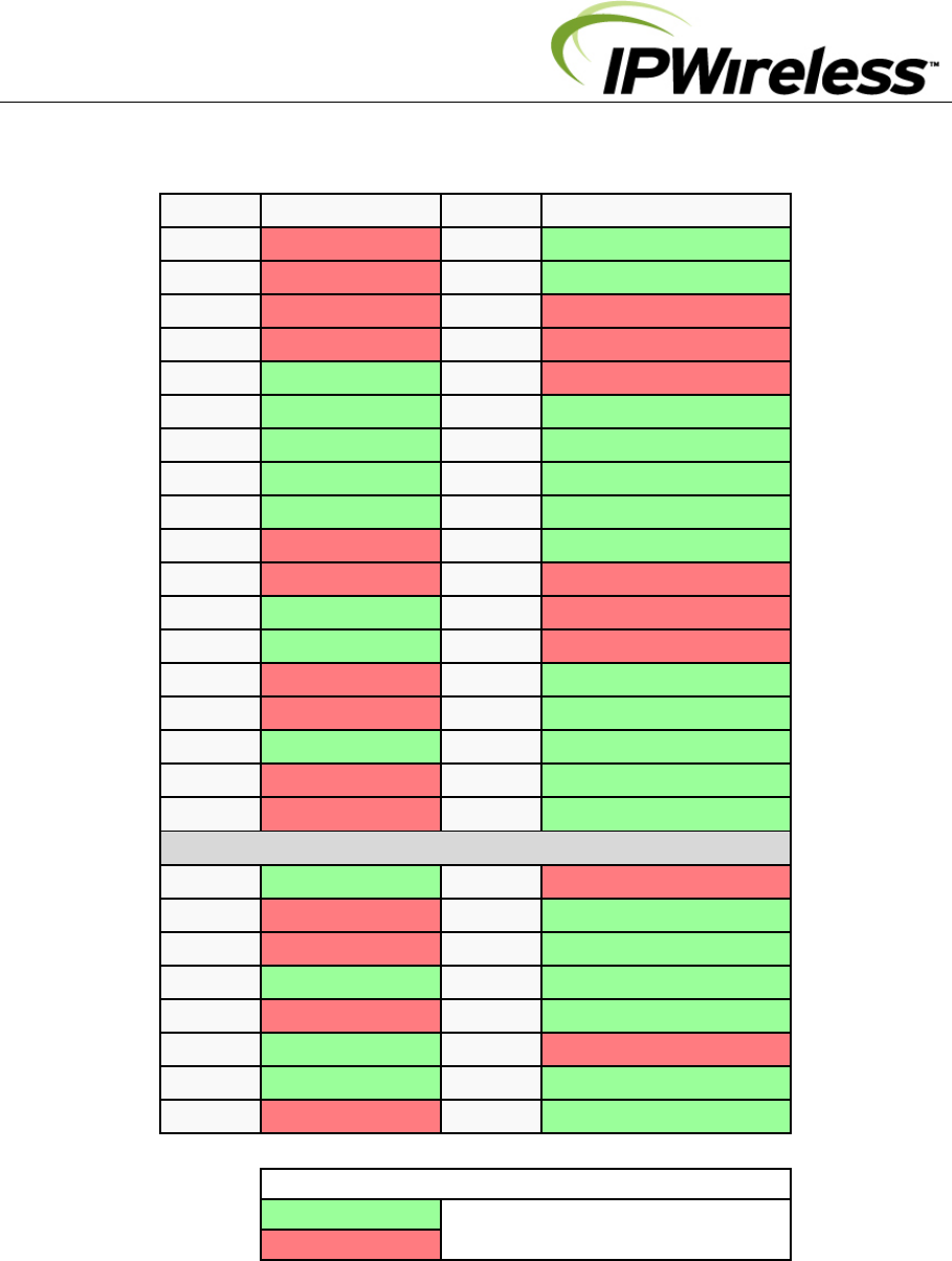
6 Annex 1: PCI Express Mini Edge Connector Pinout
PinNamePinName
51 Reserved52 +3.3Vaux
49 Reserved50 GND
47 Reserved48 +1.5V
45 Reserved46 LED_WPAN#
43GND44 LED_WLAN#
41+3.3Vaux42 LED_WWAN#
39+3.3Vaux40 GND
37GND38 USB_D+
35GND36 USB_D‐
33PETp034 GND
31PETn032 SMB_DATA
29GND30 SMB_CLK
27GND28 +1.5V
25PERp026 GND
23PERn024 +3.3Vaux
21GND22 PERST#
19Reserved20 W_DISABLE#
17Reserved18 GND
MechanicalKey
15GND16 UIM_VPP
13REFCLK+14 UIM_RESET
11REFCLK‐ 12 UIM_CLK
9GND10 UIM_DATA
7CLKREQ#8UIM_PWR
5COEX26+1.5V
3COEX14GND
1WAKE#2+3.3Vaux
Key
Used on PEM
Unused