Panasonic of North America PT-VW355N LCD PROJECTOR User Manual PT VW355N Part 4
Panasonic Corporation of North America LCD PROJECTOR PT VW355N Part 4
Contents
- 1. PT-VW355N_User Manual Part 1
- 2. PT-VW355N_User Manual Part 2
- 3. PT-VW355N_User Manual Part 3
- 4. PT-VW355N_User Manual Part 4
PT-VW355N_User Manual Part 4
![Memory Viewer functionThe Memory Viewer function makes it is possible to project the video or still image stored in the USB memory.What you can project with the Memory Viewer functionMemory Viewer function supports the following les.Still imageExtension Format Restrictionjpg/jpeg JPEGNumber of pixels: Maximum 8 000 x 8 000(For progressive JPEG, maximum 4 096 x 4 096)YUV format: Only YUV444, YUV422, and YUV411 supportedColor mode: Only RGB supportedbmp Windows BitmapNumber of pixels: Maximum 2 000 x 2 000(1-bit, 4-bit, 8-bit, 16-bit, 24-bit, and 32-bit supported)Following formats are not supported.Run-length encoding, Bit elds, Top to bottom, Transparent dataMovieExtension Codec Restriction*1Video Audio Video AudiomovH.264/MPEG-4 AVCMotion JPEGAACLinear PCMResolution:Maximum 1 920 x 1 080Minimum 240 x 180Frame rate:Maximum 30 fpsBit rate:Maximum 40 MbpsSample rate:Maximum 48 kHz(For Linear PCM,maximum 16 kHz)Channel:Maximum 2 chBit rate:Maximum 384 kbpsaviH.264/MPEG-4 AVCMotion JPEGMPEG-4MPEG-1/2 Audio Layer-3(MP3)AACLinear PCMmp4H.264/MPEG-4 AVCMPEG-4AACMPEG-4 AAC-LCmpg/mpeg MPEG-2 MPEG-1/2 Audio Layer-2wmv WMV9 WMA*1 Following movie les are not supported. fFiles with the video codec of WMV7, WMV8, DivX, or Xvid fUncompressed video fMulti-angle video fFiles with the prole of Advanced Simple Prole @ Level 0 or Advanced Simple Prole @ Level 1Note fSome information for still image / movie les can be viewed with a computer where relevant les are accessible.Operation example - For Windows computer1. Right-click a le, and click [Properties].2. Click the [Details] tab. - For Mac1. Click a le while holding down the “Control” key, and click [Get Info].2. Click the [More Info] tab. fThe maximum size of le is 2 GB. fFiles protected by Digital Rights Management (DRM) cannot be used. fThe maximum number of folder/le is up to 1 000. If it exceeds the folder/le cannot display and an error message appears. fIt maybe impossible to play even if the le is recorded in the supported format.Cautions on using USB MemoryPlease observe the following. fDo not put USB memory or its cap within close reach of children. Swallowing them may cause suffocation. fIf the smoke or questionable odor rise, remove the USB memory from the projector, and then contact your dealer. fDo not put water, chemical or oil to the USB memory. It may cause short out or re. fDo not put foreign objects or put metal objects to the USB terminal. Static electricity may cause data loss or data corruption. fDo not remove the USB memory from the computer or the projector while the USB memory is reading out or writing the data. It may cause data loss or data corruption. fDo not store the USB memory where high temperature, humid or dusty place or magnetized items are around.116 - ENGLISHChapter 5 Operation of Function - Memory Viewer function](https://usermanual.wiki/Panasonic-of-North-America/PT-VW355N.PT-VW355N-User-Manual-Part-4/User-Guide-2596843-Page-1.png)
![Note fIt is compatible with the USB memory sold in the market. fIt cannot be used the other format other than the formatted with FAT16 and FAT32.Inserting the USB memory1) Insert the USB memory directly into the <USB A (VIEWER)> terminal.Attention fWhen inserting the USB memory, conrm the direction of the plug and do not damage the terminal.Removing the USB memory1) Make sure that the USB memory is not flashing, and then unplug it.Attention fPlease note following points when removing the USB memory. - The indicator of the USB memory is blinking means that the projector is reading out the data. Do not remove the USB memory while it is blinking.- When using a USB memory without an indicator, you cannot recognize when the projector reading out the data. Please remove it from the projector after closing the memory viewer function or turning off the projector.- Do not insert and remove the USB memory in a short time. Remove the USB memory at least ve seconds after inserting. And insert it at least ve seconds after removing. When inserting or removing the USB memory, the projector takes about 5 seconds to identify the operation.Note fThe USB memory can be inserted or removed regardless of the power status of the projector.Displaying the memory viewer screen1) Insert the USB memory in which the video or still image file is stored into the <USB A (VIEWIER)> terminal. fFor more information about using USB memory, refer to “Cautions on using USB Memory”. (x page 116)2) Press the <MEMORY VIEWER> button. fThe memory viewer screen (in thumbnail or list display) will be projected. fA cursor will be displayed in the thumbnail display area or the list display area on the right of the screen. (The background is yellow.) Thumbnail display Folder list displayNote fThe display method of the Memory Viewer screen (in thumbnail or list display) can be set in [NETWORK/USB] menu → [MEMORY VIEWER] → [VIEW]. (x page 94)Operations of the Memory Viewer screenThe following describes the operations after the Memory Viewer screen displays.When displaying in thumbnail1) Press the <AUTO SETUP/CANCEL> button on the remote control or the <EASY SETTING/CANCEL> button on the control panel.ENGLISH - 117Chapter 5 Operation of Function - Memory Viewer function](https://usermanual.wiki/Panasonic-of-North-America/PT-VW355N.PT-VW355N-User-Manual-Part-4/User-Guide-2596843-Page-2.png)
![fThe cursor moves from the thumbnail display area on the right of the screen to the folder list on the upper left of the screen. (The background is orange.)2) Press as to select a folder, then press the <ENTER> button. fIf there is a folder in the lower level, it will be expanded and displayed in the folder list on the upper left of the screen. fThe selected folder (cursor position) is displayed on an orange background.3) Press asqw to select the desired file. fThe detailed information of the selected le will be displayed in the information area on the lower left of the screen.4) Press the <ENTER> button. fThe le starts playing on the full screen. fFor the detailed information on the playing order, refer to the “Playing the still image” (x page 119) or “Playing the video” (x page 120).5) Press the <AUTO SETUP/CANCEL> button on the remote control or the <EASY SETTING/CANCEL> button on the control panel to exit playing. f Exit the full screen display, and the Memory Viewer screen (in thumbnail display) is displayed. fIf you want to continue to play another le, please perform the step 1) to 4) again.Note fWhen Memory Viewer screen is displayed, each time you press the <AUTO SETUP/CANCEL> button on the remote control or the <EASY SETTING/CANCEL> button on the control panel, the cursor will move between the folder list area and the thumbnail (or list) display area. fThe display order of the thumbnail is in accordance with the setting of [NETWORK/USB] menu → [MEMORY VIEWER] → [SORT]. (x page 94)When displaying in list1) Press the <AUTO SETUP/CANCEL> button on the remote control or the <EASY SETTING/CANCEL> button on the control panel. fThe cursor moves from the list display area on the right of the screen to the folder list on the upper left of the screen. (The background is orange.)2) Press as to select a folder, then press the <ENTER> button. fIf there is a folder in the lower level, it will be expanded and displayed in the folder list on the upper left of the screen. fThe selected folder (cursor position) is displayed on an orange background.3) Press as to select the desired file. fThe detailed information of the selected le will be displayed in the information area on the lower left of the screen. 4) Press the <ENTER> button. fThe le starts playing on the full screen. fFor the detailed information on the playing order, refer to the “Playing the still image” (x page 119) or “Playing the video” (x page 120).118 - ENGLISHChapter 5 Operation of Function - Memory Viewer function](https://usermanual.wiki/Panasonic-of-North-America/PT-VW355N.PT-VW355N-User-Manual-Part-4/User-Guide-2596843-Page-3.png)
![5) Press the <AUTO SETUP/CANCEL> button on the remote control or the <EASY SETTING/CANCEL> button on the control panel to exit playing. f Exit the full screen display, and the Memory Viewer screen (in list display) is displayed. fIf you want to continue to play another le, please perform the step 1) to 4) again.Note fWhen Memory Viewer screen is displayed, each time you press the <AUTO SETUP/CANCEL> button on the remote control or the <EASY SETTING/CANCEL> button on the control panel, the cursor will move between the folder list area and the thumbnail (or list) display area. fThe display order of the list is in accordance with the setting of [NETWORK/USB] menu → [MEMORY VIEWER] → [SORT].(x page 94)Playing the still imageIntroduce the procedure to the example of the operation in the MEMORY VIEWER screen of [THUMBNAIL] display method.In the case of the MEMORY VIEWER screen of [LIST] display method, you can play with the same procedure other than the selection operation of le. Operation GuideDisplay example of auto playing (still image)When the automatic playback function is enableIntroduce the procedure of the operation under the [MEMORY VIEWER] menu → [AUTOPLAY] is set to [ON] (x page 94).All images in the same folder will play automatically when [MEMORY VIEWER] menu → [INTERVAL] or [EFFECT] is set to the special setting. (x page 94)1) Press asqw to select a file which you want to play first from the thumbnail, and then press the <ENTER> button. fIt will start playing in full screen. fPress the <ENTER> button again, the play will stop temporarily. If you want to continue the play, press the button again. fPlayback is nished, you can start playing the next le. fPress w during playing, it will skip the current playing and automatic play from the next le. fPress q during playing, it will continue automatic play back to the previous le. fPress a during playing, the image will be rotated 90 ° in the clockwise direction while maintaining the aspect ratio. fPress s during playing, the image will be rotated 90 ° in the counterclockwise direction while maintaining the aspect ratio.2) Press the <AUTO SETUP/CANCEL> button on the remote control or the <EASY SETTING/CANCEL> button on the control panel. fExit the automatic playback and returns to the MEMORY VIEWER screen (thumbnails).When the automatic playback function is disableIntroduce the procedure of the operation under the [MEMORY VIEWER] menu → [AUTOPLAY] is set to [OFF] (x page 94).In this case, it will play a le one by one.1) Press asqw to select a file from the thumbnail, and then press the <ENTER> button.ENGLISH - 119Chapter 5 Operation of Function - Memory Viewer function](https://usermanual.wiki/Panasonic-of-North-America/PT-VW355N.PT-VW355N-User-Manual-Part-4/User-Guide-2596843-Page-4.png)
![fThe selected still image will be played in full screen. fPress w to play the next le. fPress q to play back to the previous le.2) Press the <AUTO SETUP/CANCEL> button on the remote control or the <EASY SETTING/CANCEL> button on the control panel. fExit the full screen and return to the MEMORY VIEWER screen of thumbnail display method.Note fIf the number of recording pixels is less than 1 280 × 800, it will be enlarged while maintaining the aspect ratio. fIf the number of recording pixels is more than 1 280 × 800, it will be reduced display while maintaining the aspect ratio. fThe order of playback, please follow the order that you set on the [MEMORY VIEWER] menu→ [SORT] (x page 94). Even if the video les and still image les are mixed in the folder, it will be played according to the settings of the [SORT]. fThe operation guide of the bottom of the playback screen can be turned off when [MEMORY VIEWER] → [GUIDE] is set to [OFF]. (x page 94)Playing the videoIntroduce the procedure to the example of the operation in the MEMORY VIEWER screen of [THUMBNAIL] display method.In the case of the MEMORY VIEWER screen of [LIST] display method, you can play with the same procedure other than the selection operation of le. 戻るメニュー再生頭出し巻戻し 早 送りStatus displayOperation GuideTimer barDisplay example (10 speed) fast-forward during playbackWhen the automatic playback function is enableIntroduce the procedure of the operation under the [MEMORY VIEWER] menu → [AUTOPLAY] is set to [ON] (x page 94).In this case, all video les in the same folder will play automatically.1) Press asqw to select a file which you want to play first from the thumbnail, and then press the <ENTER> button. fIt will start playing in full screen. fPress the <ENTER> button to pause the playback. Press the button again to play the video at the position of pause. fPlayback is nished, you can start playing the next le. fIf you press w during playing, you can fast forward playback. In addition, the speed will be faster by pressing w each time. (3 stages) fIf you press q during playing, you can rewind playback. In addition, the speed will be faster by pressing q each time. (3 stages) fPress a during playing, it will be returned to play from the beginning. (Play from the beginning) fPress w during pausing, it will skip the current playing and automatic play from the next le. fPress q during pausing, it will automatic play from the previous le.2) Press the <AUTO SETUP/CANCEL> button on the remote control or the <EASY SETTING/CANCEL> button on the control panel. fExit the automatic playback and returns to the MEMORY VIEWER screen (thumbnails).120 - ENGLISHChapter 5 Operation of Function - Memory Viewer function](https://usermanual.wiki/Panasonic-of-North-America/PT-VW355N.PT-VW355N-User-Manual-Part-4/User-Guide-2596843-Page-5.png)
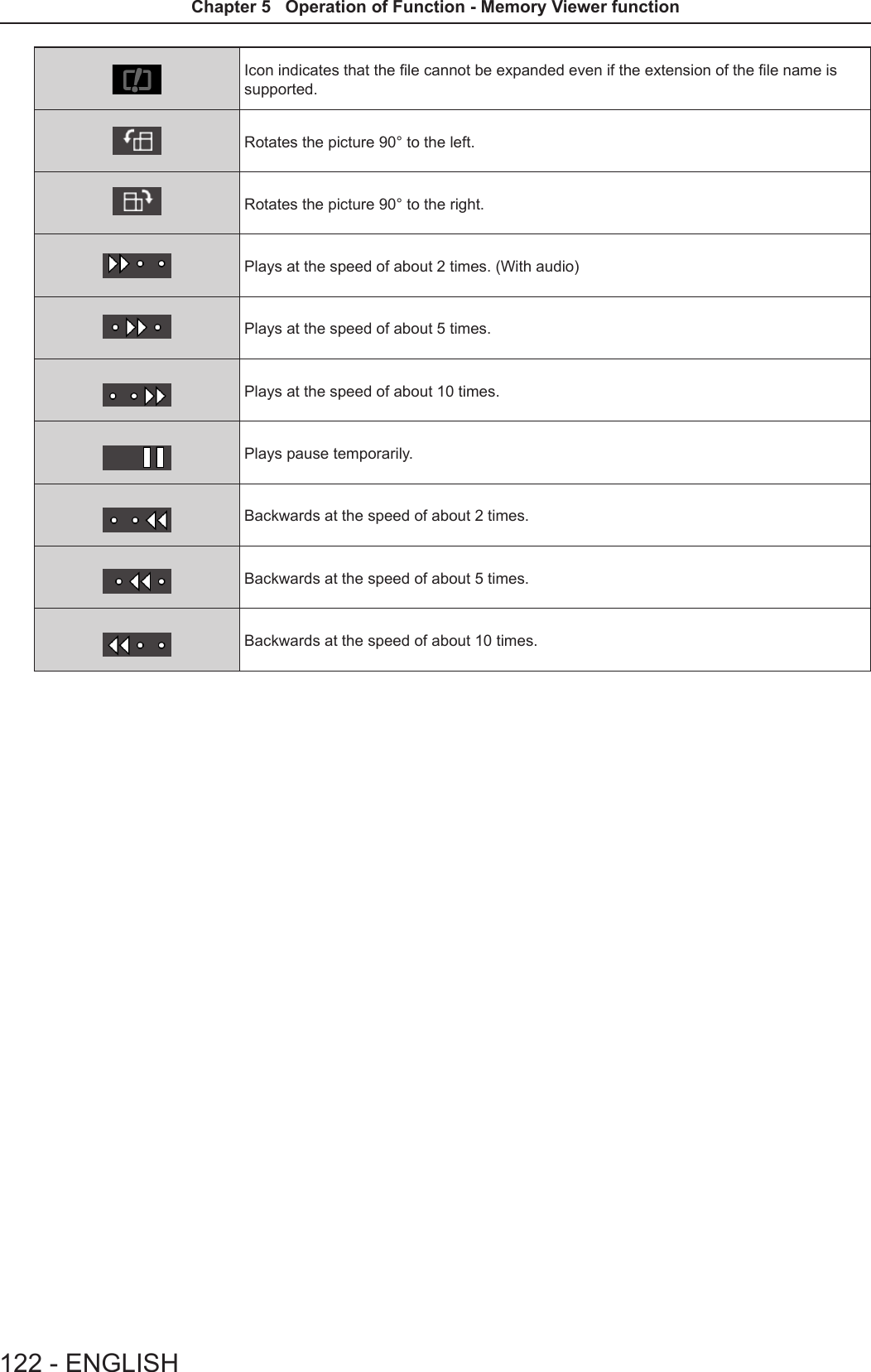
![When the automatic playback function is disableIntroduce the procedure of the operation under the [MEMORY VIEWER] menu → [AUTOPLAY] is set to [OFF] (x page 94).In this case, it will play a le one by one.1) Press asqw to select a file from the thumbnail, and then press the <ENTER> button. fIt will start playing in full screen. fPress the <ENTER> button to pause the playback. Press the button again to play the video at the position of pause. fPlayback is nished, you can start playing the next le. fIf you press w during playing, you can fast forward playback. In addition, the speed will be faster by pressing w each time. (3 stages) fIf you press q during playing, you can rewind playback. In addition, the speed will be faster by pressing q each time. (3 stages) fPress a during playing, it will be returned to play from the beginning. (Play from the beginning) fPress w during pausing, it will skip the current playing and automatic play from the next le. fPress q during pausing, it will automatic play from the previous le.2) Press the <AUTO SETUP/CANCEL> button on the remote control or the <EASY SETTING/CANCEL> button on the control panel. fExit the automatic playback and returns to the MEMORY VIEWER screen (thumbnails).Note fIf the number of recording pixels is less than 1 280 × 800, it will be enlarged while maintaining the aspect ratio. fIf the number of recording pixels is more than 1 280 × 800, it will be reduced display while maintaining the aspect ratio. fThe order of playback, please follow the order that you set on the [MEMORY VIEWER] menu→ [SORT] (x page 94). Even if the video les and still image les are mixed in the folder, it will be played according to the settings of the [SORT]. fThe operation guide of the bottom of the playback screen can be turned off when [MEMORY VIEWER] → [GUIDE] is set to [OFF]. (x page 94)Resume playing functionThe resume playing function can be used when the auto play function is disable ([MEMORY VIEWER] → [AUTOPLAY] is set to [OFF]) (x page 94).If you stop a video during playing, and then want to resume playing the same video, this function allow you to replay from the position where you stop last time. The video starts to play from the position where you stop last time in one of the following situation: fWhen you stop the video during playing and return to the Memory Viewer screen, then select the same video. fWhen you want to play the original video after playing another video le or image le.Note fDuring playing, you can press the <ENTER> button to pause the video, and press the <AUTO SETUP/CANCEL> button on the remote control or the <EASY SETTING/CANCEL> button on the control panel to exit the full screen display. The resume information (the position where you stop the video during playing) will be kept automatically. fThe maximum number of the le whose resume information (the position where you stop the video during playing) being kept is up to 50. If it exceeds, the resume information of the oldest le cannot be kept. fIt maybe impossible to resume playing exactly from where you stop last time. fWhen switching the input to the [MIRRORING] or [Panasonic APPLICATION], unplugging the power cord, removing the USB memory, the resume information will be discarded.Description of the memory viewer screenThe indication of icons on the memory viewer screen are as following: Icon indicates that can move to the upper layer. Move to the upper layer when selected. Icon indicates the lower layer of the folder. Move to the lower layer when selected. Icon indicates that the le is a still image. Icon indicates that the le is a video.ENGLISH - 121Chapter 5 Operation of Function - Memory Viewer function](https://usermanual.wiki/Panasonic-of-North-America/PT-VW355N.PT-VW355N-User-Manual-Part-4/User-Guide-2596843-Page-6.png)
![About MIRRORINGThe MIRRORING is a function to project the same images as the displayed images on the device with the projector. The MIRRORING function connects the Intel® WiDi / Intel® Pro WiDi / Miracast compatible device to the projector via wireless LAN. Connecting with the Intel® WiDi / Intel® Pro WiDi / Miracast compatible device 1) Press the <MIRRORING> button on the remote control. fSwitch the MIRRORING input, and the MIRRORING idle screen will display. fYou can also select the MIRRORING input by pressing the <INPUT SELECT> button on the control panel.Name: Name9646_Proj9646ID: 7900A8The MIRRORING idle screen2) Start the Intel® WiDi / Intel® Pro WiDi / Miracast application of the correspondent Intel® WiDi / Intel® Pro WiDi / Miracast devices. fCheck the device name / device ID which is displayed on the MIRRORING idle screen, and then select the device name on the Intel® WiDi / Intel® Pro WiDi / Miracast application.3) If the device is required to input the PIN (8-digit number), enter the PIN displayed on the MIRRORING idle screen.From Android_fed4PIN 01591057The PIN displayed on the MIRRORING idle screenNote fThe Intel® WiDi / Intel® Pro WiDi / Miracast application name and starting method may differ from devices. fFor the operation of the Intel® WiDi / Intel® Pro WiDi / Miracast application, refer to the operation instructions of the device.Disconnecting with the Intel® WiDi / Intel® Pro WiDi / Miracast compatible device Close the Intel® WiDi / Intel® Pro WiDi / Miracast application of the device. And then the MIRRORING idle screen will be projected.If you disconnect the device forcibly without closing the application, such as turning off the power of the device, it may take a longer time to display the MIRRORING idle screen. Note fMiracast is a standard that developed by Wi-Fi Alliance, it is possible to transmit the image displayed on the device wirelessly. fIntel® WiDi or Intel® Pro WiDi is a standard that developed by Intel, it is based on the Miracast and added with new technologies and functions, it is also possible to transmit the image displayed on the device wirelessly. fWhen connected with MIRRORING, the volume cannot be adjusted by pressing the <VOL-/VOL+> buttons on the remote control. fThe MIRRORING function is disabled when the [WIRELESS LAN] menu is set to [DISABLE] (x page 89). fIf a space is inserted in the projector name of [NAME CHANGE], the space in the projector name will be displayed to “_” on the MIRRORING idle screen for the projector or on the Intel® WiDi / Intel® Pro WiDi / Miracast compatible device.ENGLISH - 123Chapter 5 Operation of Function - About MIRRORING](https://usermanual.wiki/Panasonic-of-North-America/PT-VW355N.PT-VW355N-User-Manual-Part-4/User-Guide-2596843-Page-8.png)
![Lamp and Warning IndicatorsWhen an indicator lights upIf a problem should occur inside the projector, the lamp indicator <LAMP> and the warning indicator <WARNING> will inform you by lighting or blinking. Check the status of the indicators and remedy the indicated problems as follows.Attention fBefore you take a remedial measure, follow the procedure of switching the power off indicated in “Powering Off the projector”. (x page 45)Lamp indicator <LAMP>Warning indicator <WARNING>Lamp indicatorIndicator status Lighting in red Blinking in redStatus Time to replace the lamp unit. (x page 128)A problem is detected in the lamp or the power supply for the lamp.Check fWas [REPLACE LAMP] displayed when you turned on the power? fThe indicator lights up when the runtime of the lamp unit has reached 5 000 hours (when [LAMP POWER] is set to [NORMAL]). fHave you turned on the power again immediately after turning it off? fSome error has occurred in the lamp circuit. Check for uctuation (or drop) in the source voltage.Remedy fReplace the lamp unit. fWait a while until the luminous lamp cools off, and then turn on the power. fTurn off the projector, and unplug the AC power cord, and consult your dealer.Note fIf the lamp indicator <LAMP> is still lighting or blinking after taking the preceding measures, ask your dealer for repair.Warning indicatorIndicator status Lighting in red Blinking in red Blinking in red (Slow)Status Internal temperature is high (warning). Internal temperature is high (standby status).The projector detects an abnormal condition and cannot be turned on.Check fIs the air intake/exhaust port blocked? fIs the room temperature high? fIs the air lter unit dirty? _Remedy fRemove any objects that are blocking the air intake / exhaust port. fInstall the projector in a location with an ambient temperature of 0 °C (32 °F) to 40 °C (104 °F). fDo not use the projector at high altitudes of 2 700 m (8 858') or higher above sea level. fReplace the air lter unit. (x page 126) fIf the projector is turned off again, unplug the AC power cord and contact the dealer or the service center for service and checkup.Note fIf the warning indicator <WARNING> is still lighting or blinking after taking the preceding measures, ask your dealer for repair.ENGLISH - 125Chapter 6 Maintenance - Lamp and Warning Indicators](https://usermanual.wiki/Panasonic-of-North-America/PT-VW355N.PT-VW355N-User-Manual-Part-4/User-Guide-2596843-Page-10.png)
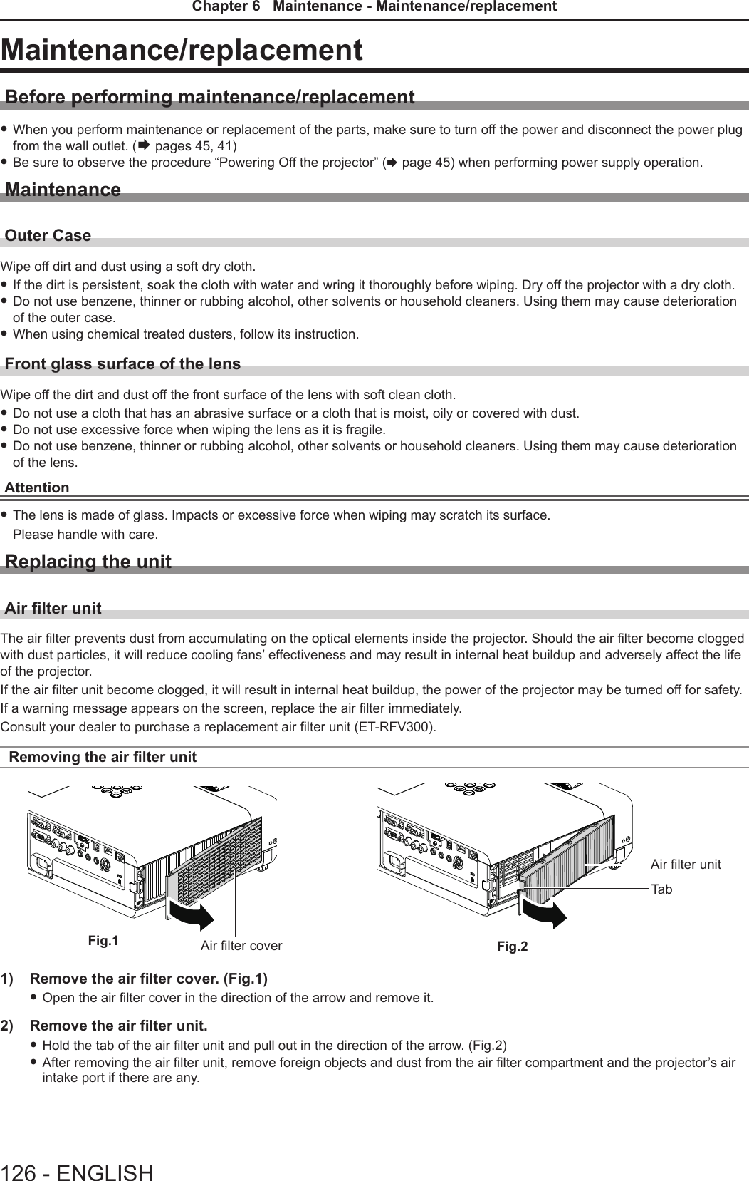
![Attaching the air lter unitTab1) Attach the unused air filter unit to the projector. fHold the air lter unit that the tab is in up-left side in the gure, put the right side in the gure rst, and press the tab side until make a click sound. fPlease press the tab of the air lter unit other than the pleated lter during installation.2) Install the air filter cover. fPerform Step 1) in “Removing the air lter unit” (x page 126) in the reverse order to close the air lter cover and press it rmly until make a click sound. fMake sure that the air lter cover is closed tightly.Resetting the filter counterBe sure to reset the lter counter after replacing the air lter unit.1) Connect the power plug, press the power <v/b> button on the control panel or the power on <b> button on the remote control.2) Press the <MENU> button to display the main menu, then press as to select [PROJECTOR SETUP].3) Press the <ENTER> button, press as to select [FILTER COUNTER].4) Press the <ENTER> button, press as to select [FILTER COUNTER RESET].5) Press the <ENTER> button. f[FILTER COUNTER RESET] conrmation is displayed. 6) Press qw to select [OK], then press the <ENTER> button. fThe lter usage time is 0 after reset.Attention fTurn off the power before you replace the air lter unit. fWhen attaching the air lter unit, make sure that the projector is stable, and work in an environment that is safe, even in the event of the air lter unit dropping. fMake sure that the air lter unit is properly attached before using the projector. If it is not attached, the projector will suck in dirt and dust causing a malfunction. fDo not put anything into the air vents. Doing so may result in malfunction of the projector. fThe air lter unit to be replaced should be an unused product. fAfter replacing the air lter, reset the lter counter. Otherwise, “FILTER COUNTER has reached the set time.” will appear on screen.Note fThe replacement cycle of the air lter unit varies greatly depending on the usage environment.Lamp unitThe lamp unit is a consumable component. Refer to “When to replace the lamp unit” (x page 128) for details about the replacement cycle.It is recommended to ask an authorized engineer to replace the lamp unit. Contact your dealer.Consult your dealer to purchase a replacement lamp unit (ET-LAV300).WarningDo not replace the lamp unit when it is hot. (Wait at least 1 hour after use.)The inside of the cover can become very hot, take care to avoid burn injuries.ENGLISH - 127Chapter 6 Maintenance - Maintenance/replacement](https://usermanual.wiki/Panasonic-of-North-America/PT-VW355N.PT-VW355N-User-Manual-Part-4/User-Guide-2596843-Page-12.png)
![Notes on the replacement of the lamp unit fThe luminous source of the lamp is made of glass and may burst if you hit it against a hard surface or drop it. Please handle with care. fA Phillips screwdriver is required for replacement of the lamp unit. fWhen replacing the lamp unit, be sure to hold it by the handle. fWhen replacing the lamp because it has stopped illuminating, there is a possibility that the lamp may be broken. If replacing the lamp of a projector which has been installed on the ceiling, you should always assume that the lamp is broken, and you should stand to the side of the lamp cover, not underneath it. Remove the lamp cover gently. Small pieces of glass may fall out when the lamp cover is opened. If pieces of glass get into your eyes or mouth, seek medical advice immediately. fThe lamp may be ruptured. Care should be taken not to scatter pieces of the broken lamp glass when replacing the lamp unit. Pieces of the broken lamp may fall from the lamp unit especially when the projector is mounted on the ceiling, so when replacing the lamp unit do not stand directly underneath it or position your face close to it. fThe lamp contains mercury. Consult your local municipality or your dealer about correct disposal of used lamp units.Attention fPanasonic takes no responsibility for any damage or malfunction of the product resulting from use of lamp units which are not manufactured by Panasonic. Use only specied lamp units.Note fThe model numbers of accessories and optional accessories are subject to change without prior notice.When to replace the lamp unitThe lamp unit is a consumable component. Since its brightness gradually decreases over time, it is necessary to replace the lamp unit regularly. The estimated duration before replacement is 5 000 hours, but the lamp may go off before 5 000 hours has elapsed depending on individual lamp characteristics, usage conditions, and the installation environment. It is recommended that the Replacement lamp unit be prepared earlier.If you continue to use the lamp unit after 5 000 hours has elapsed, the lamp turns off automatically after approximately 10 minutes, as it will cause malfunction of the projector.Lamp runtimeOn-screen display160 - ENGLISHREPLACE LAMPLAMP indicatorOver 4 800 hours The message is displayed for 30 seconds. If you press any button within the 30 seconds, the message disappears.Lights in red (even in stand-by mode).Over 5 000 hours If the power is turned on without replacing the lamp, the power automatically turns off after approximately ten min-utes to prevent the malfunction of the projector.Note fTo predict when to replace the lamp, check the lamp runtime displayed in [RUNTIME] in [STATUS] (x page 77). f5 000 hours of use is a rough guideline, but is not a guarantee. The lamp runtime differs depending on the setting of "LAMP POWER" menu.Replacing the Lamp unitAttention fWhen the projector is mounted on a ceiling, do not work with your face close to the projector. fDo not loosen other than designated screws. fAttach the lamp unit and the lamp cover securely.Lamp coverLamp cover xing screwLamp unit xing screwsHandles128 - ENGLISHChapter 6 Maintenance - Maintenance/replacement](https://usermanual.wiki/Panasonic-of-North-America/PT-VW355N.PT-VW355N-User-Manual-Part-4/User-Guide-2596843-Page-13.png)
![TroubleshootingPlease check following points. For details, see the corresponding pages.Problem Cause Reference pagePower does not turn on. fThe power cord may not be connected. fNo electric supply is at the wall outlet. fThe circuit breakers have tripped. fIs the <LAMP> indicator or <WARNING > indicator lit or blinking? fThe lamp cover has not been securely installed.———125128No picture appears. fThe video signal input source may not be connected to a terminal properly. fThe input selection setting may not be correct. fThe [BRIGHTNESS] adjustment setting may be at the minimum setting. fThe input source which is connected to the projector may have a problem. fThe AV MUTE function may be in use.385061—53, 76The picture is fuzzy. fThe lens cap is still attached to the lens. fThe lens focus may not have been set correctly. fThe projector may not be at the correct distance from the screen. fThe lens may be dirty. fThe projector may be tilted too much.23463320—The color is pale or grayish. f[COLOR] or [TINT] adjustment may be incorrect. fThe input source which is connected to the projector may not be adjusted correctly. fRGB cable is damaged.61——No sound from the internal speaker. fThe input terminals may not have been correctly connected. fThe volume may have been set to the minimum level. fThe AV MUTE function may have been turned on. fWhen the VARIABLE AUDIO OUT is plugged-in, the projector’s built-in speaker is not available. fThe MUTE function may have been turned on. fIs the audio input selection in [AUDIO SETTING] set correctly?3949, 8153, 763954, 8182The remote control does not operate. fThe batteries may be weak. fThe batteries may not have been inserted correctly. fThe remote control signal receptor on the projector may be obstructed. fThe remote control unit may be out of the operation range. fStrong light such as uorescent shine onto the signal receptor. fThe [REMOTE CONTROLLER] setting is set to [DISABLE] in [CONTROL DEVICE SETUP]. fIs the ID number setting operation correct? fCheck if the <ON/OFF> switch on the remote control is set to "ON".—29262626875425Menu screen does not appear. fIs the on-screen display function turned off (hidden)? 70The control buttons of the projector do not operate. fThe [CONTROL PANEL] setting is set to [DISABLE] in [CONTROL DEVICE SETUP]. 87The picture does not display correctly. fThere may be a problem with the VCR or other signal source. fA signal which is not compatible with the projector is being input.—141Picture from a computer does not appear. fThe cable may be longer than the optional cable. fThe external video output from a laptop computer may not be correct. ——Picture from a HDMI device does not appear or picture is not stable. fIs the HDMI cable securely connected? fTurn off the power of the projector and the connected devices. Then turn the power of the projector and the connected devices back on. fIsn’t unsupported signal cable connected?38, 39—141No sound is output from a HDMI device. fSet the sound channel of the attached device to Linear PCM. —EASY SETTING function is disabled. fTurn off and turn on the power of the projector. 83Attention fIf the problem persists, after conrming the contents of the table, please consult your dealer.130 - ENGLISHChapter 6 Maintenance - Troubleshooting](https://usermanual.wiki/Panasonic-of-North-America/PT-VW355N.PT-VW355N-User-Manual-Part-4/User-Guide-2596843-Page-15.png)
![FAQPlease refer to the following items if you have problems with the wireless LAN connection.The wireless LAN connection is interrupted suddenly. fThe picture may disappear or freeze depending on the radio wave environment. In such cases, please try the following measures. - Please make the wireless LAN connection device close to the projector. - Place away from devices that can emit electromagnetic radiation, such as microwave ovens, game machines. Do not use these devices if you are still unable to solve the problem.- If multiple wireless devices are connected with the same router, the bandwidth will be insufcient.- Please prevent from using the projector in a location prone to static electricity, such as on a carpet. fIf it happens that the wireless LAN connection is cut off unexpectedly, please set [WIRELESS LAN] in the [NETWORK/USB] menu to [DISABLE], and then perform the wireless LAN connection again so that the wireless module will be restored to the normal state.In addition, please refer to the following items if you have problems with the MIRRORING connection.MIRRORING cannot be connected. fIs the [WIRELESS LAN] menu set to [DISABLE]? fIs the input source [MIRRORING] selected correctly? fIs [MEMORY VIEWER] or [Panasonic APPLICATION] selected in [CONNECTION LOCK] menu? Please change the setting. fPlease check the setting of the Intel® WiDi / Intel® Pro WiDi / Miracast compatible device. For details about the connection method of MIRRORING, refer to the Operating Instructions of the Intel® WiDi / Intel® Pro WiDi / Miracast compatible device. fAre there any obstacles between the Intel® WiDi / Intel® Pro WiDi / Miracast compatible device and the projector? In addition, is the Intel® WiDi / Intel® Pro WiDi / Miracast compatible device far from the projector? Please remove the obstacles or make the Intel® WiDi / Intel® Pro WiDi / Miracast compatible device close to the projector. fThe column "Paired devices" will remain the connection information such as the Intel® WiDi / Intel® Pro WiDi / Miracast compatible device etc., but you cannot reconnect with the screen, please connect with the devices that can be connected from the list. fCancel the sleep state or switch the log-on user of the Intel® WiDi / Intel® Pro WiDi / Miracast compatible device, the connection may be failed. Turn off / on the wireless LAN of the device, or turn the device and the projector off and then on again. fIf you cannot connect to the projector, or the projector is not existed in the available connection device list, you can try to switch the [AUTONOMOUS GROUP OWNER] menu to [OFF] or [ON].Disconnected suddenly or Image cannot be updated. fIf the MIRRORING idle screen is not displayed, the sound cannot be output, the connection is failed, please re-boot the projector and then return the operation according to the following method. - Set [STANDBY MODE] to [ECO], turn off the power, and then turn on the power. (If [STANDBY MODE] is already set to [ECO], the procedure of the setting is not required.)- Please turn off the power and disconnect the power plug from the power outlet. - Please turn on the projector and the Intel® WiDi / Intel® Pro WiDi / Miracast compatible device.The picture or sound of MIRRORING is distorted. fSet the wireless LAN mode to [SIMPLE], [S-DIRECT] or [M-DIRECT]. fSince MIRRORING is connected wirelessly, the picture or sound may be distorted by the radio wave environment. In such cases, please try the following measures. - Please make the Intel® WiDi / Intel® Pro WiDi / Miracast compatible device close to the projector. - Place away from devices that can emit electromagnetic radiation, such as microwave ovens, game machines. Do not use these devices if you are still unable to solve the problem.- If multiple wireless devices are connected with the same router, the bandwidth will be insufcient. fIf there is a problem with the content itself, the picture may be distorted, please conrm the content. fThe picture or sound of MIRRORING is distorted depending on the Intel® WiDi / Intel® Pro WiDi / Miracast compatible device. It may be caused by the processing capability and the wireless transmission performance of the Intel® WiDi / Intel® Pro WiDi / Miracast compatible device, and it is not a malfunction of the projector.The connection of MIRRORING will be interrupted if there is no operation after connecting with the MIRRORING. fDepending on the conguration of your Intel® WiDi / Intel® Pro WiDi / Miracast compatible device, the connection may be lost in some time. Please check the saving power setting of the device. fThe problem will be improved by updating the wireless driver and rmware. Please contact with the manufacturer for the technical support about the device.ENGLISH - 131Chapter 6 Maintenance - FAQ](https://usermanual.wiki/Panasonic-of-North-America/PT-VW355N.PT-VW355N-User-Manual-Part-4/User-Guide-2596843-Page-16.png)

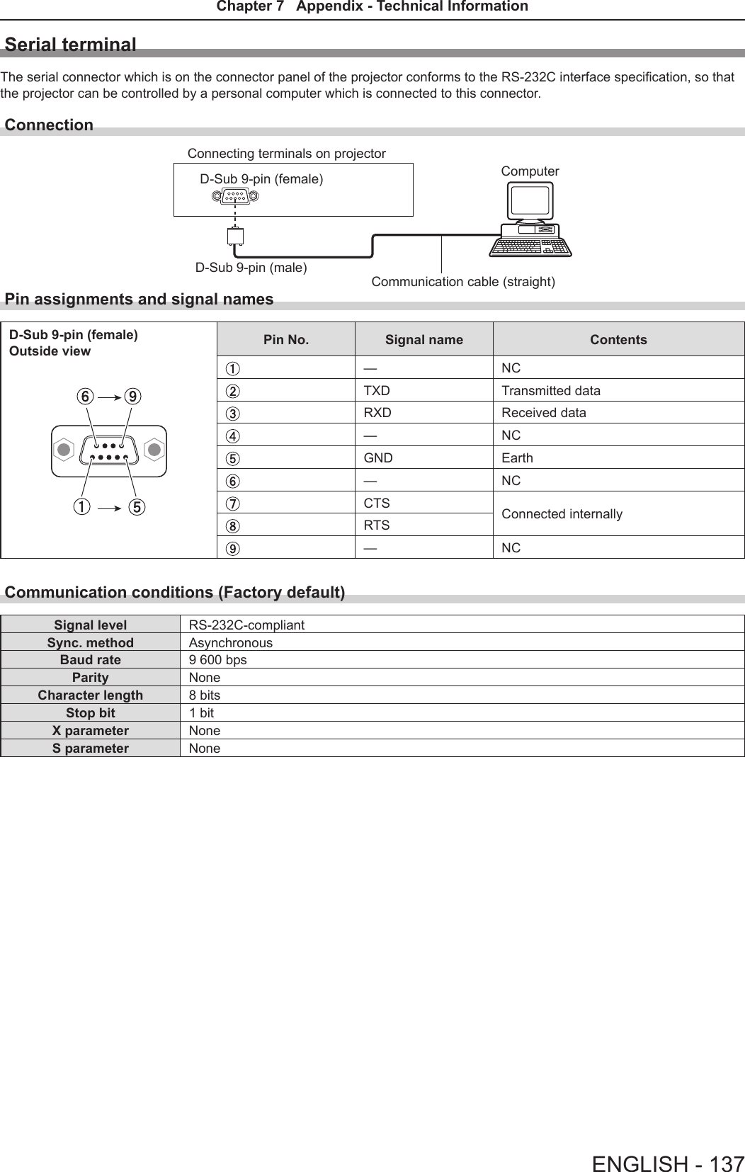
![Technical InformationPJLink protocolThe network function of the projector supports PJLink class 1, and the PJLink protocol can be used to perform projector setting and projector status query operations from a computer.Control commands The following table lists the PJLink protocol commands that can be used to control the projector. fx characters in tables are non-specic characters.Command Control details Parameter / return string RemarkPOWR Power supply control 01StandbyPower onPOWR ? Power supply status query0123StandbyPower onCool-down in progressWarm-up in progressINPT Input selection111221223151RGB 1RGB 2 VIDEO S-VIDEO HDMI NETWORK/USBINPT ? Input selection queryAVMT AV MUTE control 3031AV MUTE mode offAV MUTE mode onAVMT ? AV MUTE status queryERST ? Error status query ××××××1st byte Indicates fan errors, range 0 – 2 f0 = No error known f1 = Warning f2 = Error2nd byte Indicates lamp errors, range 0 – 23rd byte Indicates temperature errors, range 0 – 24th byte Fixed at 05th byte Indicates lter errors, range 0 – 26th byte Indicates other errors, range 0 – 2LAMP ? Lamp status query ××××××××××××1st digits (1 – 5 digits) : Lamp cumulative operating time2nd digit : 0 = Lamp off, 1 = Lamp onINST ? Input selection list query 11 12 21 22 31 51NAME ? Projector name query ××××× Returns the name set in [NAME CHANGE] of [NETWORK/USB].INF1 ? Manufacturer name query Panasonic Returns manufacturer name.INF2 ? Model name query VW355NVX425N Returns model name.INF0 ? Other information query ××××× Returns information such as version number.CLSS ? Class information query 1Returns class for PJLink.PJLink security authorization The password used for PJLink is the same as that of the password set for web control.When using the projector without security authentication, do not set a password for web control. fFor specications related to PJLink, refer to the website of Japan Business Machine and Information System Industries Association.URL http://pjlink.jbmia.or.jp/english/134 - ENGLISHChapter 7 Appendix - Technical Information](https://usermanual.wiki/Panasonic-of-North-America/PT-VW355N.PT-VW355N-User-Manual-Part-4/User-Guide-2596843-Page-19.png)
![Control commands via LANWhen WEB Control administrator rights password is set (Protect mode)Connection method 1) Obtain the IP address and port number (Initial set value = 1 024) of the projector and make a request for connection to the projector. fAcquire the IP address from the menu screen of the projector, and the port number from the WEB control page.IP address : Obtain from MAIN MENU → [NETWORK/USB] → [STATUS]Port No. : Acquire from the WEB control → [Detailed set up] → [Port set up] page2) There is a response from the projector.Data section Blank Mode Blank Random number section Termination symbolCommand example“NTCONTROL”(ASCII string)‘ ’0x20‘1’0x31‘ ’0x20“zzzzzzzz”(ASCII code hexadecimal number)(CR)0x0dData length 9 bytes 1 byte 1 byte 1 byte 8 bytes 1 byte fMode : 1 = Protect mode3) Generate a 32-byte hash value from the following data using MD5 algorithm. f“xxxxxx:yyyyy:zzzzzzzz”xxxxxx : Administrator rights user name for WEB CONTROL (Default user name is “admin1”)yyyyy : Password of above administrator rights user (Default password is “panasonic”)zzzzzzzz : 8-byte random number obtained in Step 2Command transmission method Transmit using the following command format. rTransmitted dataHeader Data section Termination symbolCommand exampleHash value(See above <Connection method>)‘0’0x30‘0’0x30Control command(ASCII string)(CR)0x0dData length 32 bytes 1 byte 1 byte Undened length 1 byte rReceive dataHeader Data section Termination symbolCommand example‘0’0x30‘0’0x30Control command(ASCII string)(CR)0x0dData length 1 byte 1 byte Undened length 1 byte rError responseString Details Termination symbolMessage"ERR1" Undened control command(CR)0x0d"ERR2" Out of parameter range"ERR3" Busy state or no-acceptable period"ERR4" Timeout or no-acceptable period"ERR5" Wrong data length"ERRA" Password mismatchData length 4 bytes ― 1 byteENGLISH - 135Chapter 7 Appendix - Technical Information](https://usermanual.wiki/Panasonic-of-North-America/PT-VW355N.PT-VW355N-User-Manual-Part-4/User-Guide-2596843-Page-20.png)
![When WEB Control administrator rights password is not set (Non-protect mode)Connection method 1) Obtain the IP address and port number (Initial set value = 1 024) of the projector and make a request for connection to the projector. fAcquire the IP address from the menu screen of the projector, and the port number from the WEB control page.IP address : Obtain from main menu → [NETWORK/USB] → [STATUS]Port No. : Acquire from the WEB control → [Detailed set up] → [Port set up] page2) There is a response from the projector. rResponse dataData section Blank Mode Termination symbolCommand example“NTCONTROL”(ASCII string)‘ ’0x20‘0’0x30(CR)0x0dData length 9 bytes 1 byte 1 byte 1 byte fMode : 0 = Non-protect modeCommand transmission method Transmit by the following command format. rTransmitted dataHeader Data section Termination symbolCommand example‘0’0x30‘0’0x30Control command(ASCII string)(CR)0x0dData length 1 byte 1 byte Undened length 1 byte rReceive dataHeader Data section Termination symbolCommand example‘0’0x30‘0’0x30Control command(ASCII string)(CR)0x0dData length 1 byte 1 byte Undened length 1 byte rResponse dataString Details Termination symbolMessage"ERR1" Undened control command(CR)0x0d"ERR2" Out of parameter range"ERR3" Busy state or no-acceptable period"ERR4" Timeout or no-acceptable period"ERR5" Wrong data length"ERRA" Password mismatchData length 4 bytes ― 1 byte136 - ENGLISHChapter 7 Appendix - Technical Information](https://usermanual.wiki/Panasonic-of-North-America/PT-VW355N.PT-VW355N-User-Manual-Part-4/User-Guide-2596843-Page-21.png)
![Basic formatTransmission from the computer starts with STX, then the ID, command, parameter, and ETX are sent in this order. Add parameters according to the details of control.STX A D I1 I2 ; C1 C2 C3 : P1 P2 Pn ETXBasic format (with sub command)S1 S2 S3 S4 S5 E P1 P2 P3 P4 P5 P6STX A D I1 I2 ; C1 C2 C3 : ETXSame as basic formatSub command (5 bytes)Operation (1 byte)“=” (Value specied using parameter is set)Parameter (6 bytes)*Symbol “+” or “-” (1 byte) and set value or ad-justment value (5 bytes)* When transmitting a command which does not need a parameter, the operation (E) and parameter are not necessary.Attention fIf a command is transmitted after the lamp starts illuminating, there may be a delay in response or the command may not be executed. Try sending or receiving any command after 60 seconds. fWhen transmitting multiple commands, be sure to wait until 0.5 seconds has elapsed after receiving the response from the projector before sending the next command. When transmitting a command which does not need a parameter, a colon (:) is not necessary.Note fIf a command cannot be executed, the “ER401” response is sent from the projector to the computer. fIf an invalid parameter is sent, the “ER402” response is sent from the projector to the computer. fID transmission in RS-232C supports ZZ (ALL) and 01 to 06. fIf a command is sent with a specied ID, a response will be sent to the computer only in the following cases. - It matches the projector ID. - [PROJECTOR ID] (x page 78) is set to [ALL]. fSTX and ETX are character codes. STX shown in hexadecimal is 02, and ETX shown in hexadecimal is 03.ID designateZZ, 01 to 06Start (1 byte)(2 byte)2 ID characters (2 bytes)Semi-colon(1 byte)3 command characters (3 bytes)Colon (1 byte)Parameter (undened length) End (1 byte)138 - ENGLISHChapter 7 Appendix - Technical Information](https://usermanual.wiki/Panasonic-of-North-America/PT-VW355N.PT-VW355N-User-Manual-Part-4/User-Guide-2596843-Page-23.png)
![Cable specications[When connected to a computer] Projector(<SERIAL IN> terminal)1NC NC 1Computer(DTE specications)2 23 34NC NC 45 56NC NC 67 78 89NC NC 9Control commandsWhen controlling the projector from a computer, the following commands are available. rProjector control commandCommand Control contents Parameter / return string RemarksPON Power on ―To check if the power is on, use the “Power query” command.POF Power offIIS INPUT selectionVIDSVDRG1RG2HD1NWPPA1MC1MV1VIDEOS-VIDEORGB1RGB2HDMINETWORKPanasonic APPLICATIONMIRRORINGMEMORY VIEWEROFZ Freeze 0[OFF]1[ON]AUU Volume upAUD Volume downDZU D. ZOOM upDZD D. ZOOM downOSH AV mute function 01AV MUTE mode offAV MUTE mode on QPW Power query 000 Standby001 Power onQ$S Lamp condition query0123Stand-byLamp ON control activeLamp ONLamp OFF control active[MENU LOCK PASSWORD] operationsTo revert to the factory default password (AAAA), perform the following operations while the screen prompting input of [MENU LOCK PASSWORD] is displayed.1) Press the <AUTO SETUP/CANCEL> button on the remote control for at least three seconds.2) Press s for at least three seconds.ENGLISH - 139Chapter 7 Appendix - Technical Information](https://usermanual.wiki/Panasonic-of-North-America/PT-VW355N.PT-VW355N-User-Manual-Part-4/User-Guide-2596843-Page-24.png)
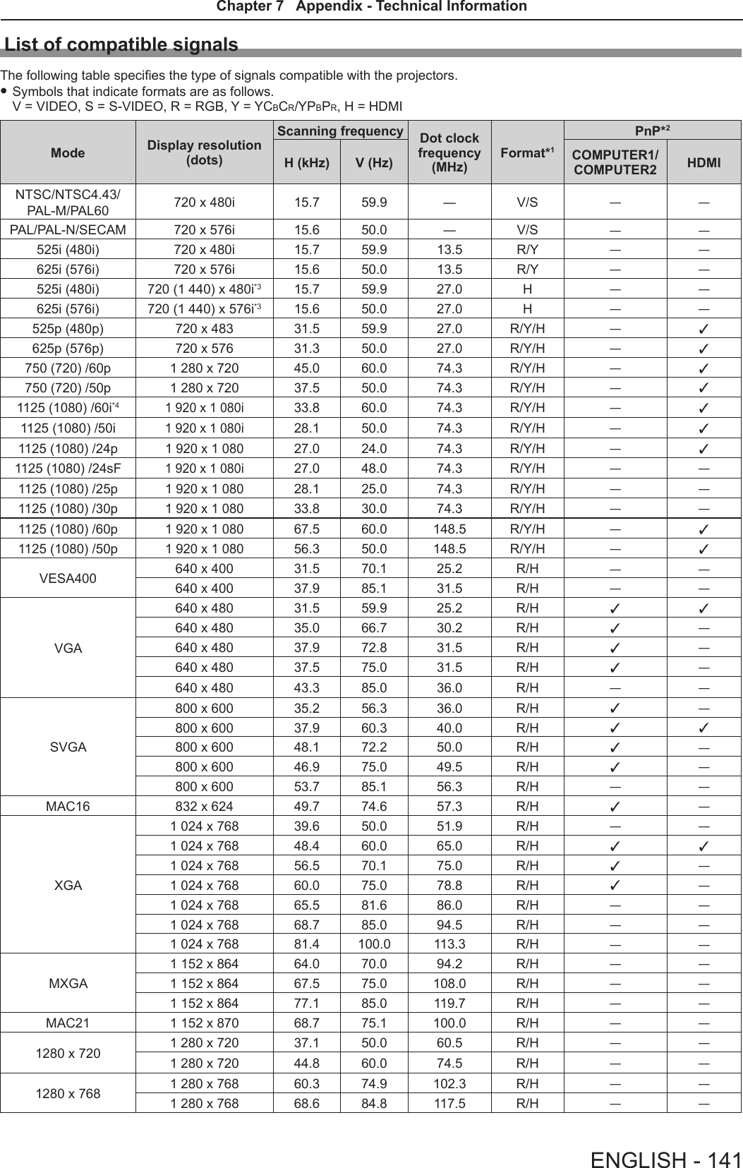
![Two window display combination listSub WindowCOMPUTER1 COMPUTER2HDMI VIDEO S-VIDEOMain Window RGB YCBCR/YPBPRRGBCOMPUTER1 RGB ― ― ― l― ―YCBCR/YPBPR― ― ― l― ―COMPUTER2 RGB ― ― ― l― ―HDMI l l l ―l lVIDEO ― ― ― l― ―S-VIDEO ― ― ― l― ― l : Picture in Picture combinations are enabled. ―: Picture in Picture combinations are disabled.Note f[MEMORY VIEWER], [MIRRORING] and [Panasonic APPLICATION] do not support two window display function. fWhen setting the movie-based signal 1080/24p, 1080/24sF,1080/25p, 1080/30p, 1080/50p or 1080/60p for HDMI input, the two window display function will be disabled. fThe image of the sub window picture may be distorted depending on the combination of signals. fWhen the selected input combinations or the input signals are not correspond with the two window display, the message "CANNOT DISPLAY THIS INPUT COMBINATION IN P IN P" will be displayed.140 - ENGLISHChapter 7 Appendix - Technical Information](https://usermanual.wiki/Panasonic-of-North-America/PT-VW355N.PT-VW355N-User-Manual-Part-4/User-Guide-2596843-Page-25.png)
![SpecicationsPower supply For North America: 120 V (120 V alternating current), 50 Hz/60 HzFor other countries: 100 V - 240 V (100 V - 240 V alternating current), 50 Hz/60 HzPower con-sumptionProjecting For North America: 3.2 A, 320 WFor other countries: 3.7 A-1.5 A, 320 WIn standby modeWhen [STANDBY MODE] of [ECO MANAGEMENT] is set to [ECO] : 0.5 W *1When [STANDBY MODE] of [ECO MANAGEMENT] is set to [NETWORK] : 6 W *2When [STANDBY MODE] of [ECO MANAGEMENT] is set to [NORMAL] : 14 WWhen [STANDBY MODE] of [ECO MANAGEMENT] is set to [NORMAL], and [IN STAND-BY MODE] of [AUDIO SETTING] is set to [ON] : 28 WLCD panelPanel size PT-VW355N 1.5 cm (0.59") (aspect ratio 16 : 10)PT-VX425N 1.6 cm (0.63") (aspect ratio 4 : 3)Display method 3 transparent LCD panels (RGB)Drive method Active matrix methodPixels PT-VW355N 1 024 000 (1 280 x 800) x 3 panelsPT-VX425N 786 432 (1 024 x 768) x 3 panelsLens Manual zoom : 1.6x Manual focus : F 1.6 to 1.9, f 15.31 mm to 24.64 mmLuminous lamp 240 W UHM lamp Light output *3PT-VW355N 4 000 lmPT-VX425N 4 500 lmContrast ratio *312 000 : 1 (all white / all black)([LAMP POWER] is set to [NORMAL], meanwhile [IRIS] is set to [ON])Appli-cable scanning frequen-cy *4for Video signal (in-cluding S-video)Horizontal : 15.73 kHz, Vertical : 59.94 Hz Horizontal : 15.63 kHz, Vertical : 50 Hzfor RGB signal Horizontal 15 kHz to 100 kHz, Vertical 50 Hz to 100 HzDot clock frequency: 140 MHz or lessfor YPBPR signal[525i(480i)] Horizontal 15.73 kHz, Vertical 59.94 Hz[625i(576i)] Horizontal 15.63 kHz, Vertical 50 Hz[525p(480p)] Horizontal 31.47 kHz, Vertical 59.94 Hz[625p(576p)] Horizontal 31.25 kHz, Vertical 50 Hz[750(720)/60p] Horizontal 45.00 kHz, Vertical 60 Hz[750(720)/50p] Horizontal 37.50 kHz, Vertical 50 Hz[1125(1080)/60i] Horizontal 33.75 kHz, Vertical 60 Hz[1125(1080)/50i] Horizontal 28.13 kHz, Vertical 50 Hz[1125(1080)/60p] Horizontal 67.50 kHz, Vertical 60 Hz[1125(1080)/50p] Horizontal 56.25 kHz, Vertical 50 Hz[1125(1080)/24p] Horizontal 27.00 kHz, Vertical 24 Hz[1125(1080)/24sF] Horizontal 27.00 kHz, Vertical 48 Hz[1125(1080)/25p] Horizontal 28.13 kHz, Vertical 25 Hz[1125(1080)/30p] Horizontal 33.75 kHz, Vertical 30 Hzfor HDMI signal525i(480i)*5, 625i(576i)*5, 525p(480p), 625p(576p), 750(720)/60p, 750(720)/50p, 1125(1080)/24p, 1125(1080)/24sF, 1125(1080)/30p, 1125(1080)/60p, 1125(1080)/50p, 1125(1080)/60i, 1125(1080)/50iDisplayable resolution: VGA to WUXGA (non-interlace)Dot clock frequency: up to 162 MHzColor system 7 (NTSC, NTSC4.43, PAL, PAL-N, PAL-M, SECAM, PAL60)Projection size 0.76 m -7.62 m (30"-300")Screen aspect ratio PT-VW355N 16 : 10PT-VX425N 4 : 3Projection scheme [FRONT/DESK], [FRONT/CEILING], [REAR/DESK], [REAR/CEILING] (Menu setting system)Speaker 1 (4.0 cm round-type)Maximum usable volume output 10 WENGLISH - 145Chapter 7 Appendix - Specications](https://usermanual.wiki/Panasonic-of-North-America/PT-VW355N.PT-VW355N-User-Manual-Part-4/User-Guide-2596843-Page-30.png)
![Termi-nals<COMPUTER 1 IN>1 (High-density D-sub 15 pin female)[RGB signal] 0.7 V [p-p] 75 Ω (When G-SYNC: 1.0 V [p-p] 75 Ω) HD/SYNC TTL high impedance, automatic positive/negative polarity compatible VD TTL high impedance, automatic positive/negative polarity compatible (SYNC/HD and VD do not support 3 value SYNC.)[YPBPR signal] Y: 1.0 V [p-p] including synchronization signal, PBPR: 0.7 V [p-p] 75 Ω<COMPUTER 2 IN/1 OUT>1 (High-density D-sub 15 pin female)[RGB signal] 0.7 V [p-p] 75 Ω (When G-SYNC: 1.0 V [p-p] 75 Ω) HD/SYNC TTL high impedance, automatic positive/negative polarity compatible VD TTL high impedance, automatic positive/negative polarity compatible (SYNC/HD and VD do not support 3 value SYNC.)<VIDEO IN> 1 (Pin jack 1.0 V [p-p] 75 Ω)<S-VIDEO IN> 1 (Mini DIN 4 pin, Y 1.0 V [p-p], C 0.286 V [p-p] 75 Ω, S1 signal compatible)<HDMI IN> 1 (HDMI 19 pin, HDCP and Deep color compatible)Audio signals: Linear PCM (Sampling frequency: 48 kHz/44.1 kHz/32 kHz)<AUDIO IN>2 (M3 stereo mini jack, 0.5 V [rms], input impedance 22 kΩ and more)(<AUDIO IN 2 (MIC IN)> terminal support MIC input)1 (Pin jack x 2 (L-R), 0.5 V [rms], input impedance 22 kΩ and more)<VARIABLE AUDIO OUT>1 (M3 stereo mini jack, stereo monitor output compatible,0 V [rms] to 2.0 V [rms] variable, output impedance 2.2 kΩ and less)<USB A/VIEWER> USB connector (type A x 1)<USB B/DISPLAY>USB connector (type B x 1)<SERIAL IN> 1 (D-sub 9 pin, RS-232C compliant, for computer control use)<LAN> 1 (for RJ-45 network connection, PJLink compatible, 10Base-T/100Base-TX)Wireless LANSpecication standardsFor North America:IEEE802.11b/g/n : 2.412 GHz - 2.462 GHzIEEE802.11a/n : 5.180 GHz - 5.825 GHz (except 5.600 GHz - 5.650 GHz)For other counties:IEEE802.11b/g/n : 2.412 GHz - 2.472 GHzIEEE802.11a/n : 5.745 GHz - 5.805 GHzModulation DBPSK, DQPSK, CCK, BPSK, QPSK, 16QAM, 64QAM, MIMOTransmission speed IEEE 802.11b : Up to 11 MbpsIEEE 802.11b/a : Up to 54 MbpsIEEE 802.11n : Up to 300 Mbps Wireless channelFor North America:IEEE802.11b/g/n: 1~11 channelIEEE802.11a/n: 36/40/44/48/52/56/60/64/100/104/108/112/116/132/136/140/149/153/157/161/165 channelFor other counties:IEEE802.11b/g/n: Passive scanningIEEE802.11a/n: Passive scanningCommunication distance Approx. 30 m (98'5") (depends on the usage environment)Security Infrastructure modeWPA-PSK (TKIP/AES), WPA2-PSK (TKIP/AES), WEP (128 bit/64 bit), WPA-EAP/WPA2-EAP (PEAP [MS-CHAPv2/GTC], EAP-FAST [MS-CHAPv2/GTC], EAP-TTLS [MD5/MS-CHAPv2]Power cable length 2.0 m (78-3/4") Cabinet Molded plasticDimensionsWidth: 352 mm (13-7/8")Height: 98 mm (3-27/32") (when the adjustable feet shortened)Depth: 279.4 mm (11") Weight Approx. 3.4 kg (7.5 lbs.) *6Noise level *3When set to [NORMAL] in [LAMP POWER] : 37 dBWhen set to [ECO] in [LAMP POWER] : 29 dB146 - ENGLISHChapter 7 Appendix - Specications](https://usermanual.wiki/Panasonic-of-North-America/PT-VW355N.PT-VW355N-User-Manual-Part-4/User-Guide-2596843-Page-31.png)
![Dimensions<Unit : mm (inch)>113.0 (4-7/16")255.0 (10-1/32")352.0 (13-7/8")24.4 (31/32")98.0 (3-27/32")90.0 (3-17/32")326.0 (12-27/32") 198.0 (7-25/32")54.8 (2-5/32") Actual dimension may differ by product.*1 When the [PROJECTOR SETUP] menu → [ECO MANAGEMENT] → [STANDBY MODE] is set to [ECO], the network function (both wireless LAN and wired LAN) cannot be used in standby mode.*2 When the [PROJECTOR SETUP] menu → [ECO MANAGEMENT] → [STANDBY MODE] is set to [NETWORK], only the Wake on LAN function can be used in standby mode via wired LAN. When the [PROJECTOR SETUP] menu → [ECO MANAGEMENT] → [STANDBY MODE] is set to [NETWORK], the power consumption is normally within 6 W in standby status. If the input source was switched to [MEMORY VIEWER] or [Panasonic APPLICATION] before the projector turns into standby, the power consumption in standby status may be more than 6 W.*3 Measurement, measuring conditions and method of notation all comply with ISO21118 international standards.*4 For details of video signals that can be projected using this projector, refer to “List of compatible signals”. (x page 141)*5 Pixel-Repetition signal (dot clock frequency 27.0 MHz) only*6 This is an average value. It may differ depending on individual product.*7 [LAMP POWER] will be switched to [ECO] automatically when the operating environment temperature is 35 °C to 40 °C.Note fThe part numbers of accessories and separately sold components are subject to change without notice.Operating environmentOperating environment temperature *7: 0 °C (32 °F) to 40 °C (104 °F) (Elevation: below 1 400 m; [HIGH ALTITUDE MODE]: [OFF])0 °C (32 °F) to 30 °C (86 °F) (Elevation: 1 400 m ~ 2 000 m; [HIGH ALTITUDE MODE]: [HIGH1])0 °C (32 °F) to 30 °C (86 °F) (Elevation: 2 000 m ~ 2 700 m; [HIGH ALTITUDE MODE]: [HIGH2])Operating environment humidity: 20 % to 80 % (no condensation)Remote controlPower supply DC 3 V (battery (AAA/R03 or AAA/LR03 Type ) x 2)Operating range Approx. 7 m (22'11-5/8") (when operated directly in front of receptor)Weight 102 g (3.60 ozs.) (including batteries)Dimensions Width : 48 mm (1-7/8"), Length : 145 mm (5-23/32"), Height : 27 mm (1-1/16")ENGLISH - 147Chapter 7 Appendix - Specications](https://usermanual.wiki/Panasonic-of-North-America/PT-VW355N.PT-VW355N-User-Manual-Part-4/User-Guide-2596843-Page-32.png)
![IndexAAbout MIRRORING ........................123Accessing from the Web browser ..... 99Accessories ......................................23<AC IN> terminal .............................. 26Adjusting adjustable feet ..................35[ADVANCED MENU] ........................62[AMX D.D.] ........................................93[ASPECT] .........................................68Attaching the Lens Cap ....................30[AUDIO SETTING] ............................81<AUTO SETUP/CANCEL> buttonRemote control ........................25, 49[AUTO SETUP SETTING] ................73<AV MUTE> buttonRemote control ........................25, 53B[BACK COLOR] ................................ 73Basic operations by using the remote control ...............................................49[BRIGHTNESS] ................................61CCD-ROM ...........................................24Ceiling mount bracket safeguards .. 147[CLOCK PHASE] .............................. 67[CLOSED CAPTION SETTING] .......71[COLOR] ...........................................61[COLOR TEMPERATURE] ............... 62<COMPUTER 1> buttonRemote control ........................25, 50<COMPUTER 2> buttonRemote control ........................25, 50[COMPUTER 2 SELECT] ................. 77Connecting .......................................36Connecting the power cord...............41[CONNECTION LOCK] .....................92[CONTRAST] ....................................60[CONTROL DEVICE SETUP] ...........87[Crestron Connected (TM)] ...............93D[DAYLIGHT VIEW] ............................63<DEFAULT> buttonRemote control ........................25, 57Dimensions .....................................146[DISPLAY OPTION] .......................... 70[DOT CLOCK] ...................................67<D.ZOOM +/-> buttonsRemote control ........................25, 52E<EASY SETTING/CANCEL> buttonProjector body ............................... 27[EASY SETTING] .............................83[ECO MANAGEMENT] ..................... 79[EMULATE] .......................................80<ENTER> buttonProjector body ............................... 27Remote control ..............................25FFAQ ................................................131[FILTER COUNTER] .........................83[FRAME LOCK] ................................68<FREEZE> buttonRemote control ........................25, 53<FUNCTION> buttonRemote control ........................25, 50[FUNCTION BUTTON] .....................81GGlossary for network functions .......142H<HDMI> buttonRemote control ........................25, 50[HDMI SIGNAL LEVEL] ....................71[HIGH ALTITUDE MODE] ................. 78I<ID ALL> buttonRemote control ........................25, 54<ID SET> buttonRemote control ........................25, 54[INITIALIZE] ......................................96[INITIALIZE ALL]...............................84[INITIAL START UP] .........................78<INPUT SELECT> buttonProjector body ............................... 27Installation mode ..............................32[IRIS].................................................62K[KEYSTONE] ....................................65<KEYSTONE> buttonRemote control ........................25, 49LLamp indicator .......................... 27, 125[LAMP POWER] ...............................79[LANGUAGE]....................................69List of compatible signals ...............140[LIVE MODE CUT IN] .......................93MMain menu ........................................57Maintenance/replacement ..............126[MEMORY VIEWER] ..................94, 95<MEMORY VIEWER> buttonRemote control ........................25, 50<MENU> buttonProjector body ............................... 27Remote control ........................25, 56[MENU LOCK] ..................................86[MENU LOCK PASSWORD] ............86Menu Navigation...............................56<MIRRORING> buttonRemote control ........................25, 51[MULTI-LIVE] .................................... 94<MUTE> buttonRemote control ........................25, 54N[NAME CHANGE] .............................92Network connections ........................96[NETWORK CONTROL] ...................93[NETWORK/USB] .............................88[NOISE REDUCTION] ...................... 63O[ON-SCREEN DISPLAY] .................. 70Optional accessories ........................24[OTHER FUNCTIONS] ..................... 75[OVER SCAN] ..................................67P<Panasonic APP> buttonRemote control ........................25, 51[PASSWORD] .............................85, 92[PASSWORD CHANGE] ............85, 93[PICTURE] ........................................60[PICTURE MODE] ............................ 60[P IN P] .............................................75<P IN P> buttonRemote control ........................25, 53PJLink protocol ............................... 133[POSITION] ......................................65Power buttonProjector body ............................... 27Power indicator ...........................27, 41Powering Off the Projector ...............45Powering On the Projector ...............42Power on buttonRemote control ..............................25Power standby buttonRemote control ..............................25Precautions for use...........................18Projecting..........................................46[PROJECTION METHOD] ................78[PROJECTOR ID] ............................. 78[PROJECTOR SETUP] ....................77[P-TIMER] .........................................74<P-TIMER> buttonRemote control ........................25, 54RRead this rst!.....................................2Remote control .................................25<RETURN> buttonRemote control ........................25, 57[RGB/YPBPR] / [RGB/YCBCR] ..........64S[SCREEN SETTING] ........................ 72[SECURITY] .....................................85Setting up .........................................32[SHARPNESS] .................................61[SHIFT] .............................................66[SIGNAL SEARCH] ..........................73Specications .................................144[STARTUP LOGO] ............................ 72[STATUS] .................................... 77, 95Sub-menu ......................................... 58[SXGA MODE] ..................................73T[TEST PATTERN] .............................83[TEXT CHANGE] ..............................86[TEXT DISPLAY] ..............................86[TINT] ................................................61Troubleshooting ...................... 130, 131[TV-SYSTEM] ...................................64Two window display combination list ........................................................139V<VIDEO/S-VIDEO> buttonRemote control ........................25, 50W[WIDE MODE] ..................................73[WIRED LAN] ....................................88[WIRELESS DETAILED SETUP] ......89[WIRELESS LAN] ............................. 89ENGLISH - 149Chapter 7 Appendix - Index](https://usermanual.wiki/Panasonic-of-North-America/PT-VW355N.PT-VW355N-User-Manual-Part-4/User-Guide-2596843-Page-34.png)