Panasonic of North America PT-VW355N LCD PROJECTOR User Manual PT VW355N Part 4
Panasonic Corporation of North America LCD PROJECTOR PT VW355N Part 4
Contents
- 1. PT-VW355N_User Manual Part 1
- 2. PT-VW355N_User Manual Part 2
- 3. PT-VW355N_User Manual Part 3
- 4. PT-VW355N_User Manual Part 4
PT-VW355N_User Manual Part 4
Memory Viewer function
The Memory Viewer function makes it is possible to project the video or still image stored in the USB memory.
What you can project with the Memory Viewer function
Memory Viewer function supports the following les.
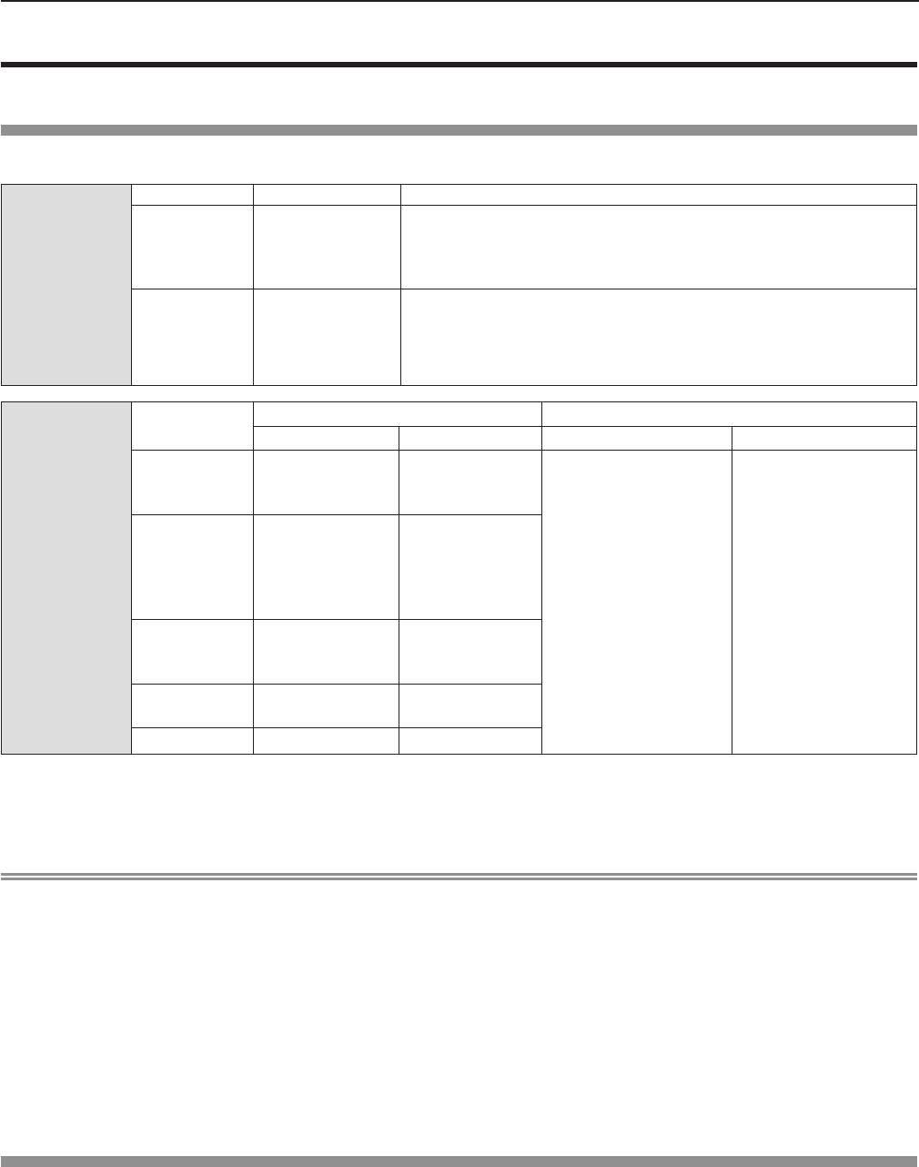
Still image
Extension Format Restriction
jpg/jpeg JPEG
Number of pixels: Maximum 8 000 x 8 000
(For progressive JPEG, maximum 4 096 x 4 096)
YUV format: Only YUV444, YUV422, and YUV411 supported
Color mode: Only RGB supported
bmp Windows Bitmap
Number of pixels: Maximum 2 000 x 2 000
(1-bit, 4-bit, 8-bit, 16-bit, 24-bit, and 32-bit supported)
Following formats are not supported.
Run-length encoding, Bit elds, Top to bottom, Transparent data
Movie
Extension Codec Restriction*1
Video Audio Video Audio
mov
H.264/MPEG-4
AVC
Motion JPEG
AAC
Linear PCM
Resolution:
Maximum 1 920 x 1 080
Minimum 240 x 180
Frame rate:
Maximum 30 fps
Bit rate:
Maximum 40 Mbps
Sample rate:
Maximum 48 kHz
(For Linear PCM,
maximum 16 kHz)
Channel:
Maximum 2 ch
Bit rate:
Maximum 384 kbps
avi
H.264/MPEG-4
AVC
Motion JPEG
MPEG-4
MPEG-1/2 Audio
Layer-3
(MP3)
AAC
Linear PCM
mp4
H.264/MPEG-4
AVC
MPEG-4
AAC
MPEG-4 AAC-LC
mpg/mpeg MPEG-2 MPEG-1/2 Audio
Layer-2
wmv WMV9 WMA
*1 Following movie les are not supported.
fFiles with the video codec of WMV7, WMV8, DivX, or Xvid
fUncompressed video
fMulti-angle video
fFiles with the prole of Advanced Simple Prole @ Level 0 or Advanced Simple Prole @ Level 1
Note
fSome information for still image / movie les can be viewed with a computer where relevant les are accessible.
Operation example
- For Windows computer
1. Right-click a le, and click [Properties].
2. Click the [Details] tab.
- For Mac
1. Click a le while holding down the “Control” key, and click [Get Info].
2. Click the [More Info] tab.
fThe maximum size of le is 2 GB.
fFiles protected by Digital Rights Management (DRM) cannot be used.
fThe maximum number of folder/le is up to 1 000. If it exceeds the folder/le cannot display and an error message appears.
fIt maybe impossible to play even if the le is recorded in the supported format.
Cautions on using USB Memory
Please observe the following.
fDo not put USB memory or its cap within close reach of children. Swallowing them may cause suffocation.
fIf the smoke or questionable odor rise, remove the USB memory from the projector, and then contact your dealer.
fDo not put water, chemical or oil to the USB memory. It may cause short out or re.
fDo not put foreign objects or put metal objects to the USB terminal. Static electricity may cause data loss or data corruption.
fDo not remove the USB memory from the computer or the projector while the USB memory is reading out or writing the
data. It may cause data loss or data corruption.
fDo not store the USB memory where high temperature, humid or dusty place or magnetized items are around.
116 - ENGLISH
Chapter 5 Operation of Function - Memory Viewer function
Note
fIt is compatible with the USB memory sold in the market.
fIt cannot be used the other format other than the formatted with FAT16 and FAT32.
Inserting the USB memory
1) Insert the USB memory directly into the <USB A (VIEWER)> terminal.
Attention
fWhen inserting the USB memory, conrm the direction of the plug and do not damage the terminal.
Removing the USB memory
1) Make sure that the USB memory is not flashing, and then unplug it.
Attention
fPlease note following points when removing the USB memory.
- The indicator of the USB memory is blinking means that the projector is reading out the data. Do not remove the USB
memory while it is blinking.
- When using a USB memory without an indicator, you cannot recognize when the projector reading out the data. Please
remove it from the projector after closing the memory viewer function or turning off the projector.
- Do not insert and remove the USB memory in a short time. Remove the USB memory at least ve seconds after inserting.
And insert it at least ve seconds after removing. When inserting or removing the USB memory, the projector takes about
5 seconds to identify the operation.
Note
fThe USB memory can be inserted or removed regardless of the power status of the projector.
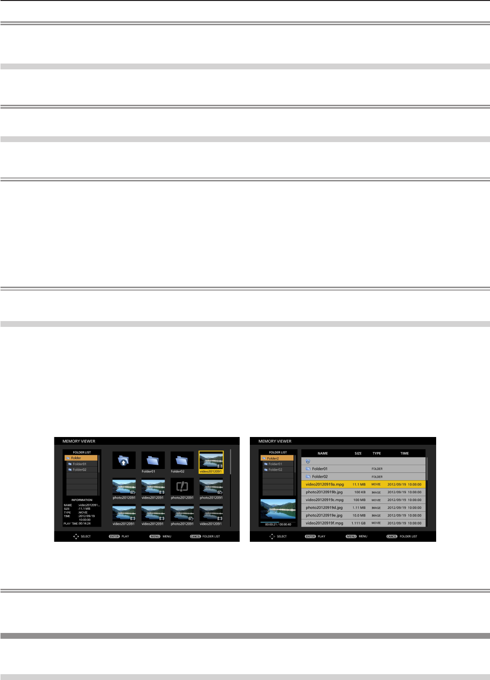
Displaying the memory viewer screen
1) Insert the USB memory in which the video or still image file is stored into the <USB A (VIEWIER)>
terminal.
fFor more information about using USB memory, refer to “Cautions on using USB Memory”. (x page 116)
2) Press the <MEMORY VIEWER> button.
fThe memory viewer screen (in thumbnail or list display) will be projected.
fA cursor will be displayed in the thumbnail display area or the list display area on the right of the screen. (The
background is yellow.)
Thumbnail display Folder list display
Note
fThe display method of the Memory Viewer screen (in thumbnail or list display) can be set in [NETWORK/USB] menu →
[MEMORY VIEWER] → [VIEW]. (x page 94)
Operations of the Memory Viewer screen
The following describes the operations after the Memory Viewer screen displays.
When displaying in thumbnail
1) Press the <AUTO SETUP/CANCEL> button on the remote control or the <EASY SETTING/CANCEL>
button on the control panel.
ENGLISH - 117
Chapter 5 Operation of Function - Memory Viewer function
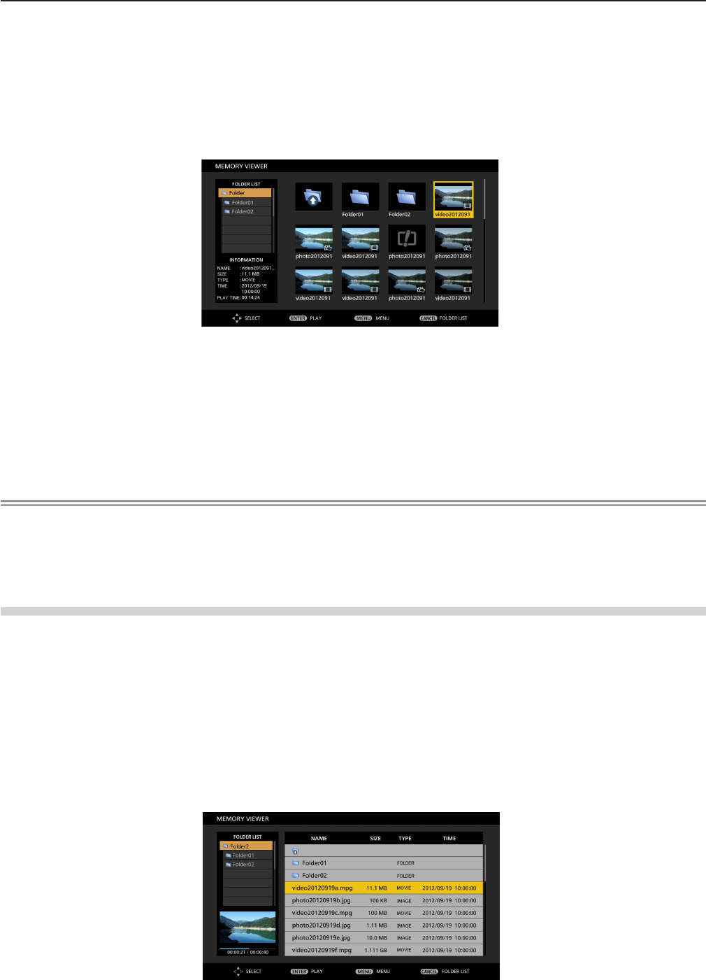
fThe cursor moves from the thumbnail display area on the right of the screen to the folder list on the upper left of the
screen. (The background is orange.)
2) Press as to select a folder, then press the <ENTER> button.
fIf there is a folder in the lower level, it will be expanded and displayed in the folder list on the upper left of the screen.
fThe selected folder (cursor position) is displayed on an orange background.
3) Press asqw to select the desired file.
fThe detailed information of the selected le will be displayed in the information area on the lower left of the screen.
4) Press the <ENTER> button.
fThe le starts playing on the full screen.
fFor the detailed information on the playing order, refer to the “Playing the still image” (x page 119) or “Playing the
video” (x page 120).
5) Press the <AUTO SETUP/CANCEL> button on the remote control or the <EASY SETTING/CANCEL>
button on the control panel to exit playing.
f Exit the full screen display, and the Memory Viewer screen (in thumbnail display) is displayed.
fIf you want to continue to play another le, please perform the step 1) to 4) again.
Note
fWhen Memory Viewer screen is displayed, each time you press the <AUTO SETUP/CANCEL> button on the remote control
or the <EASY SETTING/CANCEL> button on the control panel, the cursor will move between the folder list area and the
thumbnail (or list) display area.
fThe display order of the thumbnail is in accordance with the setting of [NETWORK/USB] menu → [MEMORY VIEWER] →
[SORT]. (x page 94)
When displaying in list
1) Press the <AUTO SETUP/CANCEL> button on the remote control or the <EASY SETTING/CANCEL>
button on the control panel.
fThe cursor moves from the list display area on the right of the screen to the folder list on the upper left of the screen.
(The background is orange.)
2) Press as to select a folder, then press the <ENTER> button.
fIf there is a folder in the lower level, it will be expanded and displayed in the folder list on the upper left of the screen.
fThe selected folder (cursor position) is displayed on an orange background.
3) Press as to select the desired file.
fThe detailed information of the selected le will be displayed in the information area on the lower left of the screen.
4) Press the <ENTER> button.
fThe le starts playing on the full screen.
fFor the detailed information on the playing order, refer to the “Playing the still image” (x page 119) or “Playing the
video” (x page 120).
118 - ENGLISH
Chapter 5 Operation of Function - Memory Viewer function

5) Press the <AUTO SETUP/CANCEL> button on the remote control or the <EASY SETTING/CANCEL>
button on the control panel to exit playing.
f Exit the full screen display, and the Memory Viewer screen (in list display) is displayed.
fIf you want to continue to play another le, please perform the step 1) to 4) again.
Note
fWhen Memory Viewer screen is displayed, each time you press the <AUTO SETUP/CANCEL> button on the remote control
or the <EASY SETTING/CANCEL> button on the control panel, the cursor will move between the folder list area and the
thumbnail (or list) display area.
fThe display order of the list is in accordance with the setting of [NETWORK/USB] menu → [MEMORY VIEWER] → [SORT].
(x page 94)
Playing the still image
Introduce the procedure to the example of the operation in the MEMORY VIEWER screen of [THUMBNAIL] display method.
In the case of the MEMORY VIEWER screen of [LIST] display method, you can play with the same procedure other than the
selection operation of le.
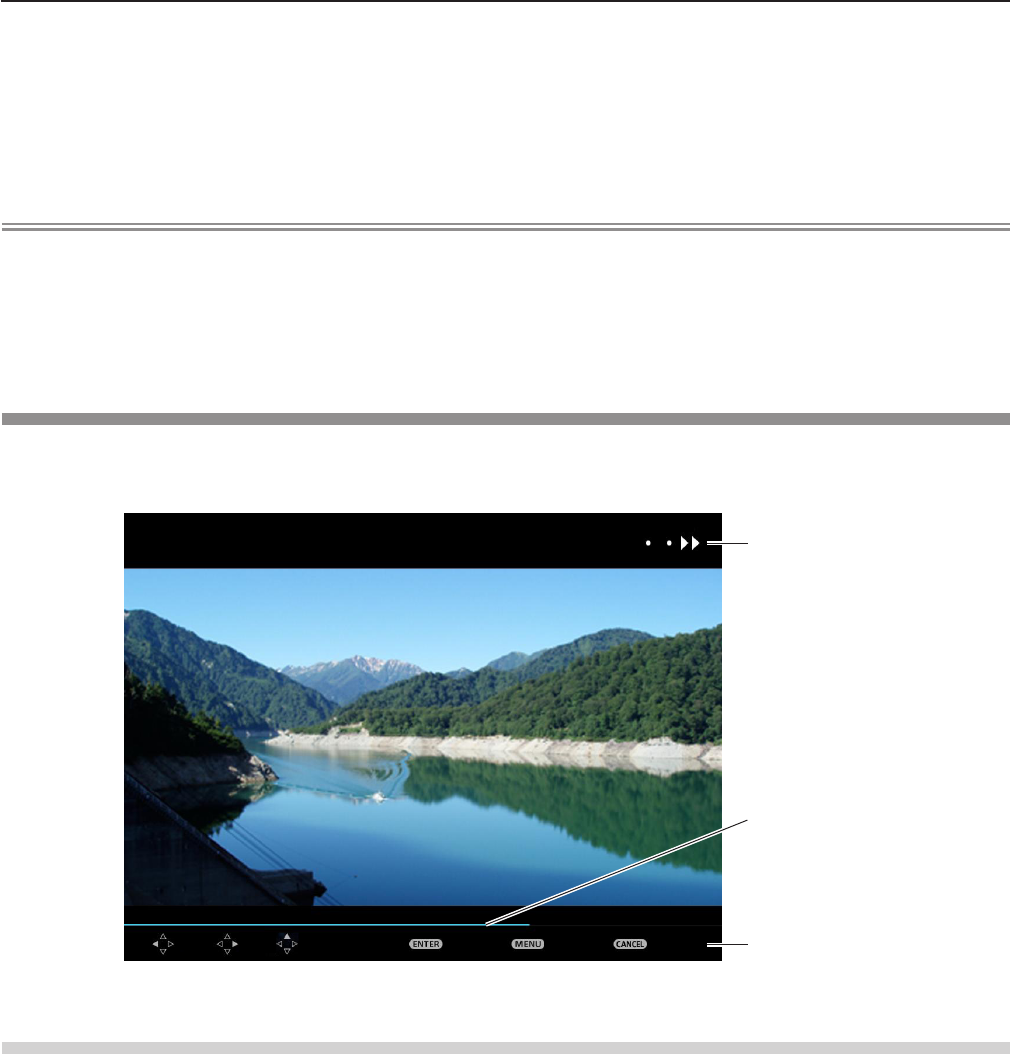
Operation Guide
Display example of auto playing (still image)
When the automatic playback function is enable
Introduce the procedure of the operation under the [MEMORY VIEWER] menu → [AUTOPLAY] is set to [ON] (x page 94).
All images in the same folder will play automatically when [MEMORY VIEWER] menu → [INTERVAL] or [EFFECT] is set to the
special setting. (x page 94)
1) Press asqw to select a file which you want to play first from the thumbnail, and then press the
<ENTER> button.
fIt will start playing in full screen.
fPress the <ENTER> button again, the play will stop temporarily. If you want to continue the play, press the button again.
fPlayback is nished, you can start playing the next le.
fPress w during playing, it will skip the current playing and automatic play from the next le.
fPress q during playing, it will continue automatic play back to the previous le.
fPress a during playing, the image will be rotated 90 ° in the clockwise direction while maintaining the aspect ratio.
fPress s during playing, the image will be rotated 90 ° in the counterclockwise direction while maintaining the aspect
ratio.
2) Press the <AUTO SETUP/CANCEL> button on the remote control or the <EASY SETTING/CANCEL>
button on the control panel.
fExit the automatic playback and returns to the MEMORY VIEWER screen (thumbnails).
When the automatic playback function is disable
Introduce the procedure of the operation under the [MEMORY VIEWER] menu → [AUTOPLAY] is set to [OFF] (x page 94).
In this case, it will play a le one by one.
1) Press asqw to select a file from the thumbnail, and then press the <ENTER> button.
ENGLISH - 119
Chapter 5 Operation of Function - Memory Viewer function
fThe selected still image will be played in full screen.
fPress w to play the next le.
fPress q to play back to the previous le.
2) Press the <AUTO SETUP/CANCEL> button on the remote control or the <EASY SETTING/CANCEL>
button on the control panel.
fExit the full screen and return to the MEMORY VIEWER screen of thumbnail display method.
Note
fIf the number of recording pixels is less than 1 280 × 800, it will be enlarged while maintaining the aspect ratio.
fIf the number of recording pixels is more than 1 280 × 800, it will be reduced display while maintaining the aspect ratio.
fThe order of playback, please follow the order that you set on the [MEMORY VIEWER] menu→ [SORT] (x page 94).
Even if the video les and still image les are mixed in the folder, it will be played according to the settings of the [SORT].
fThe operation guide of the bottom of the playback screen can be turned off when [MEMORY VIEWER] → [GUIDE] is set to
[OFF]. (x page 94)
Playing the video
Introduce the procedure to the example of the operation in the MEMORY VIEWER screen of [THUMBNAIL] display method.
In the case of the MEMORY VIEWER screen of [LIST] display method, you can play with the same procedure other than the
selection operation of le.
戻るメニュー再生頭出し巻戻し 早 送り
Status display
Operation Guide
Timer bar
Display example (10 speed) fast-forward during playback
When the automatic playback function is enable
Introduce the procedure of the operation under the [MEMORY VIEWER] menu → [AUTOPLAY] is set to [ON] (x page 94).
In this case, all video les in the same folder will play automatically.
1) Press asqw to select a file which you want to play first from the thumbnail, and then press the
<ENTER> button.
fIt will start playing in full screen.
fPress the <ENTER> button to pause the playback. Press the button again to play the video at the position of pause.
fPlayback is nished, you can start playing the next le.
fIf you press w during playing, you can fast forward playback. In addition, the speed will be faster by pressing w each
time. (3 stages)
fIf you press q during playing, you can rewind playback. In addition, the speed will be faster by pressing q each time. (3
stages)
fPress a during playing, it will be returned to play from the beginning. (Play from the beginning)
fPress w during pausing, it will skip the current playing and automatic play from the next le.
fPress q during pausing, it will automatic play from the previous le.
2) Press the <AUTO SETUP/CANCEL> button on the remote control or the <EASY SETTING/CANCEL>
button on the control panel.
fExit the automatic playback and returns to the MEMORY VIEWER screen (thumbnails).
120 - ENGLISH
Chapter 5 Operation of Function - Memory Viewer function

When the automatic playback function is disable
Introduce the procedure of the operation under the [MEMORY VIEWER] menu → [AUTOPLAY] is set to [OFF] (x page 94).
In this case, it will play a le one by one.
1) Press asqw to select a file from the thumbnail, and then press the <ENTER> button.
fIt will start playing in full screen.
fPress the <ENTER> button to pause the playback. Press the button again to play the video at the position of pause.
fPlayback is nished, you can start playing the next le.
fIf you press w during playing, you can fast forward playback. In addition, the speed will be faster by pressing w each
time. (3 stages)
fIf you press q during playing, you can rewind playback. In addition, the speed will be faster by pressing q each time. (3
stages)
fPress a during playing, it will be returned to play from the beginning. (Play from the beginning)
fPress w during pausing, it will skip the current playing and automatic play from the next le.
fPress q during pausing, it will automatic play from the previous le.
2) Press the <AUTO SETUP/CANCEL> button on the remote control or the <EASY SETTING/CANCEL>
button on the control panel.
fExit the automatic playback and returns to the MEMORY VIEWER screen (thumbnails).
Note
fIf the number of recording pixels is less than 1 280 × 800, it will be enlarged while maintaining the aspect ratio.
fIf the number of recording pixels is more than 1 280 × 800, it will be reduced display while maintaining the aspect ratio.
fThe order of playback, please follow the order that you set on the [MEMORY VIEWER] menu→ [SORT] (x page 94).
Even if the video les and still image les are mixed in the folder, it will be played according to the settings of the [SORT].
fThe operation guide of the bottom of the playback screen can be turned off when [MEMORY VIEWER] → [GUIDE] is set to
[OFF]. (x page 94)
Resume playing function
The resume playing function can be used when the auto play function is disable ([MEMORY VIEWER] → [AUTOPLAY] is set
to [OFF]) (x page 94).
If you stop a video during playing, and then want to resume playing the same video, this function allow you to replay from the
position where you stop last time.
The video starts to play from the position where you stop last time in one of the following situation:
fWhen you stop the video during playing and return to the Memory Viewer screen, then select the same video.
fWhen you want to play the original video after playing another video le or image le.
Note
fDuring playing, you can press the <ENTER> button to pause the video, and press the <AUTO SETUP/CANCEL> button on
the remote control or the <EASY SETTING/CANCEL> button on the control panel to exit the full screen display. The resume
information (the position where you stop the video during playing) will be kept automatically.
fThe maximum number of the le whose resume information (the position where you stop the video during playing) being
kept is up to 50. If it exceeds, the resume information of the oldest le cannot be kept.
fIt maybe impossible to resume playing exactly from where you stop last time.
fWhen switching the input to the [MIRRORING] or [Panasonic APPLICATION], unplugging the power cord, removing the USB
memory, the resume information will be discarded.
Description of the memory viewer screen
The indication of icons on the memory viewer screen are as following:
Icon indicates that can move to the upper layer. Move to the upper layer when selected.
Icon indicates the lower layer of the folder. Move to the lower layer when selected.
Icon indicates that the le is a still image.
Icon indicates that the le is a video.
ENGLISH - 121
Chapter 5 Operation of Function - Memory Viewer function

Icon indicates that the le cannot be expanded even if the extension of the le name is
supported.
Rotates the picture 90° to the left.
Rotates the picture 90° to the right.
Plays at the speed of about 2 times. (With audio)
Plays at the speed of about 5 times.
Plays at the speed of about 10 times.
Plays pause temporarily.
Backwards at the speed of about 2 times.
Backwards at the speed of about 5 times.
Backwards at the speed of about 10 times.
122 - ENGLISH
Chapter 5 Operation of Function - Memory Viewer function
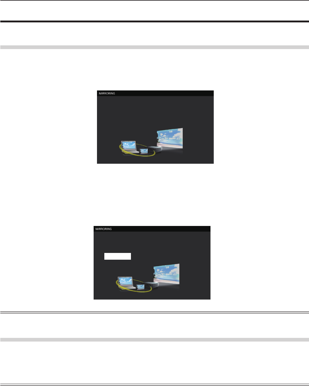
About MIRRORING
The MIRRORING is a function to project the same images as the displayed images on the device with the projector. The
MIRRORING function connects the Intel® WiDi / Intel® Pro WiDi / Miracast compatible device to the projector via wireless LAN.
Connecting with the Intel® WiDi / Intel® Pro WiDi / Miracast compatible device
1) Press the <MIRRORING> button on the remote control.
fSwitch the MIRRORING input, and the MIRRORING idle screen will display.
fYou can also select the MIRRORING input by pressing the <INPUT SELECT> button on the control panel.
Name: Name9646_Proj9646
ID: 7900A8
The MIRRORING idle screen
2) Start the Intel® WiDi / Intel® Pro WiDi / Miracast application of the correspondent Intel® WiDi / Intel® Pro
WiDi / Miracast devices.
fCheck the device name / device ID which is displayed on the MIRRORING idle screen, and then select the device
name on the Intel® WiDi / Intel® Pro WiDi / Miracast application.
3) If the device is required to input the PIN (8-digit number), enter the PIN displayed on the MIRRORING
idle screen.
From Android_fed4
PIN 01591057
The PIN displayed on the MIRRORING idle screen
Note
fThe Intel® WiDi / Intel® Pro WiDi / Miracast application name and starting method may differ from devices.
fFor the operation of the Intel® WiDi / Intel® Pro WiDi / Miracast application, refer to the operation instructions of the device.
Disconnecting with the Intel® WiDi / Intel® Pro WiDi / Miracast compatible device
Close the Intel® WiDi / Intel® Pro WiDi / Miracast application of the device. And then the MIRRORING idle screen will be
projected.
If you disconnect the device forcibly without closing the application, such as turning off the power of the device, it may take a
longer time to display the MIRRORING idle screen.
Note
fMiracast is a standard that developed by Wi-Fi Alliance, it is possible to transmit the image displayed on the device
wirelessly.
fIntel® WiDi or Intel® Pro WiDi is a standard that developed by Intel, it is based on the Miracast and added with new
technologies and functions, it is also possible to transmit the image displayed on the device wirelessly.
fWhen connected with MIRRORING, the volume cannot be adjusted by pressing the <VOL-/VOL+> buttons on the remote
control.
fThe MIRRORING function is disabled when the [WIRELESS LAN] menu is set to [DISABLE] (x page 89).
fIf a space is inserted in the projector name of [NAME CHANGE], the space in the projector name will be displayed to “_” on
the MIRRORING idle screen for the projector or on the Intel® WiDi / Intel® Pro WiDi / Miracast compatible device.
ENGLISH - 123
Chapter 5 Operation of Function - About MIRRORING

Chapter 6 Maintenance
This chapter describes methods of inspection when there are problems, maintenance, and
replacement of the units.
124 - ENGLISH
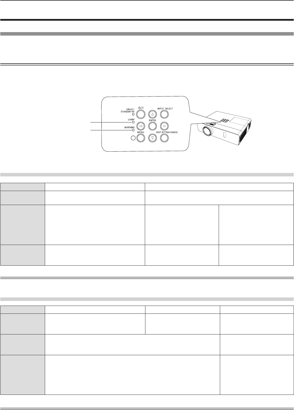
Lamp and Warning Indicators
When an indicator lights up
If a problem should occur inside the projector, the lamp indicator <LAMP> and the warning indicator <WARNING> will inform
you by lighting or blinking. Check the status of the indicators and remedy the indicated problems as follows.
Attention
fBefore you take a remedial measure, follow the procedure of switching the power off indicated in “Powering Off the
projector”. (x page 45)
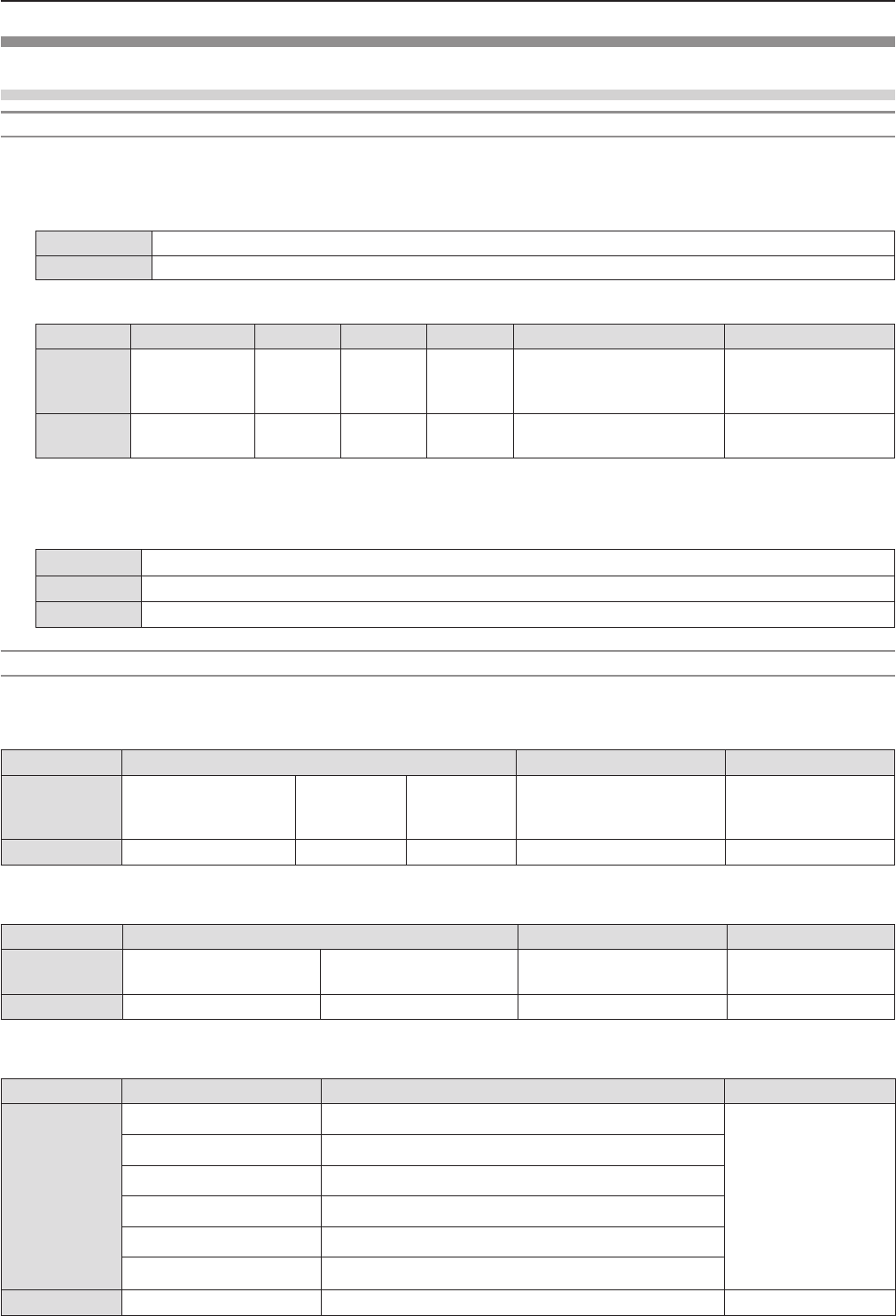
Lamp indicator <LAMP>
Warning indicator <WARNING>
Lamp indicator
Indicator status Lighting in red Blinking in red
Status Time to replace the lamp unit.
(x page 128)
A problem is detected in the lamp or the power supply for the
lamp.
Check
fWas [REPLACE LAMP] displayed
when you turned on the power?
fThe indicator lights up when the
runtime of the lamp unit has reached
5 000 hours (when [LAMP POWER] is
set to [NORMAL]).
fHave you turned on the
power again immediately
after turning it off?
fSome error has occurred in
the lamp circuit. Check for
uctuation (or drop) in the
source voltage.
Remedy fReplace the lamp unit.
fWait a while until the
luminous lamp cools off,
and then turn on the power.
fTurn off the projector, and
unplug the AC power cord,
and consult your dealer.
Note
fIf the lamp indicator <LAMP> is still lighting or blinking after taking the preceding measures, ask your dealer for repair.
Warning indicator
Indicator status Lighting in red Blinking in red Blinking in red (Slow)
Status Internal temperature is high (warning). Internal temperature is high
(standby status).
The projector detects an
abnormal condition and
cannot be turned on.
Check
fIs the air intake/exhaust port blocked?
fIs the room temperature high?
fIs the air lter unit dirty?
_
Remedy
fRemove any objects that are blocking the air intake / exhaust port.
fInstall the projector in a location with an ambient temperature of 0 °C
(32 °F) to 40 °C (104 °F).
fDo not use the projector at high altitudes of 2 700 m (8 858') or higher
above sea level.
fReplace the air lter unit. (x page 126)
fIf the projector is turned off
again, unplug the AC power
cord and contact the dealer
or the service center for
service and checkup.
Note
fIf the warning indicator <WARNING> is still lighting or blinking after taking the preceding measures, ask your dealer for
repair.
ENGLISH - 125
Chapter 6 Maintenance - Lamp and Warning Indicators
Maintenance/replacement
Before performing maintenance/replacement
fWhen you perform maintenance or replacement of the parts, make sure to turn off the power and disconnect the power plug
from the wall outlet. (Æ pages 45, 41)
fBe sure to observe the procedure “Powering Off the projector” (x page 45) when performing power supply operation.
Maintenance
Outer Case
Wipe off dirt and dust using a soft dry cloth.
fIf the dirt is persistent, soak the cloth with water and wring it thoroughly before wiping. Dry off the projector with a dry cloth.
fDo not use benzene, thinner or rubbing alcohol, other solvents or household cleaners. Using them may cause deterioration
of the outer case.
fWhen using chemical treated dusters, follow its instruction.
Front glass surface of the lens
Wipe off the dirt and dust off the front surface of the lens with soft clean cloth.
fDo not use a cloth that has an abrasive surface or a cloth that is moist, oily or covered with dust.
fDo not use excessive force when wiping the lens as it is fragile.
fDo not use benzene, thinner or rubbing alcohol, other solvents or household cleaners. Using them may cause deterioration
of the lens.
Attention
fThe lens is made of glass. Impacts or excessive force when wiping may scratch its surface.
Please handle with care.
Replacing the unit
Air lter unit
The air lter prevents dust from accumulating on the optical elements inside the projector. Should the air lter become clogged
with dust particles, it will reduce cooling fans’ effectiveness and may result in internal heat buildup and adversely affect the life
of the projector.
If the air lter unit become clogged, it will result in internal heat buildup, the power of the projector may be turned off for safety.
If a warning message appears on the screen, replace the air lter immediately.
Consult your dealer to purchase a replacement air lter unit (ET-RFV300).
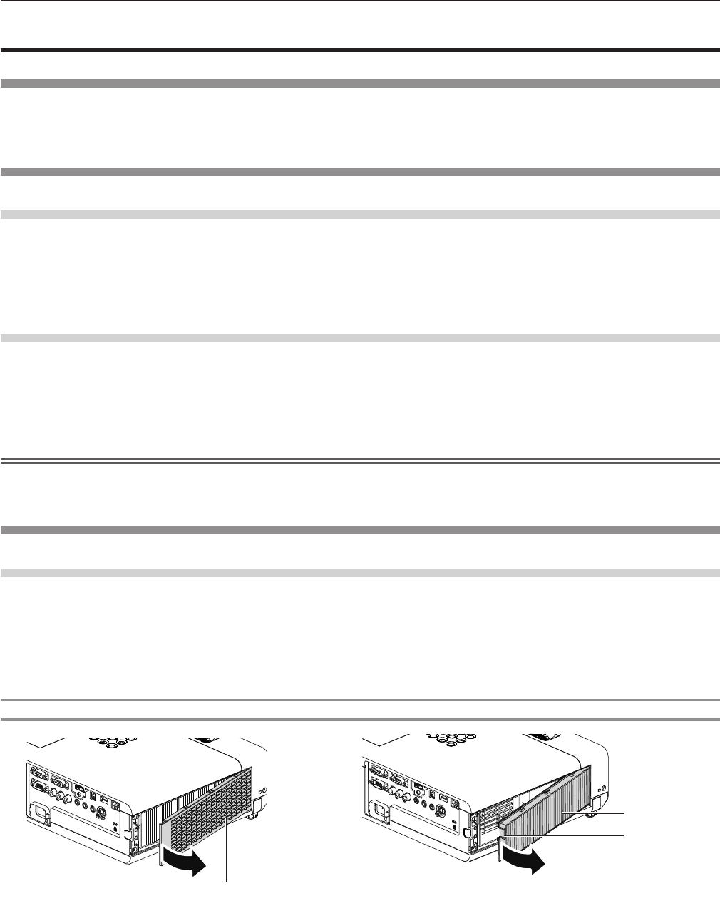
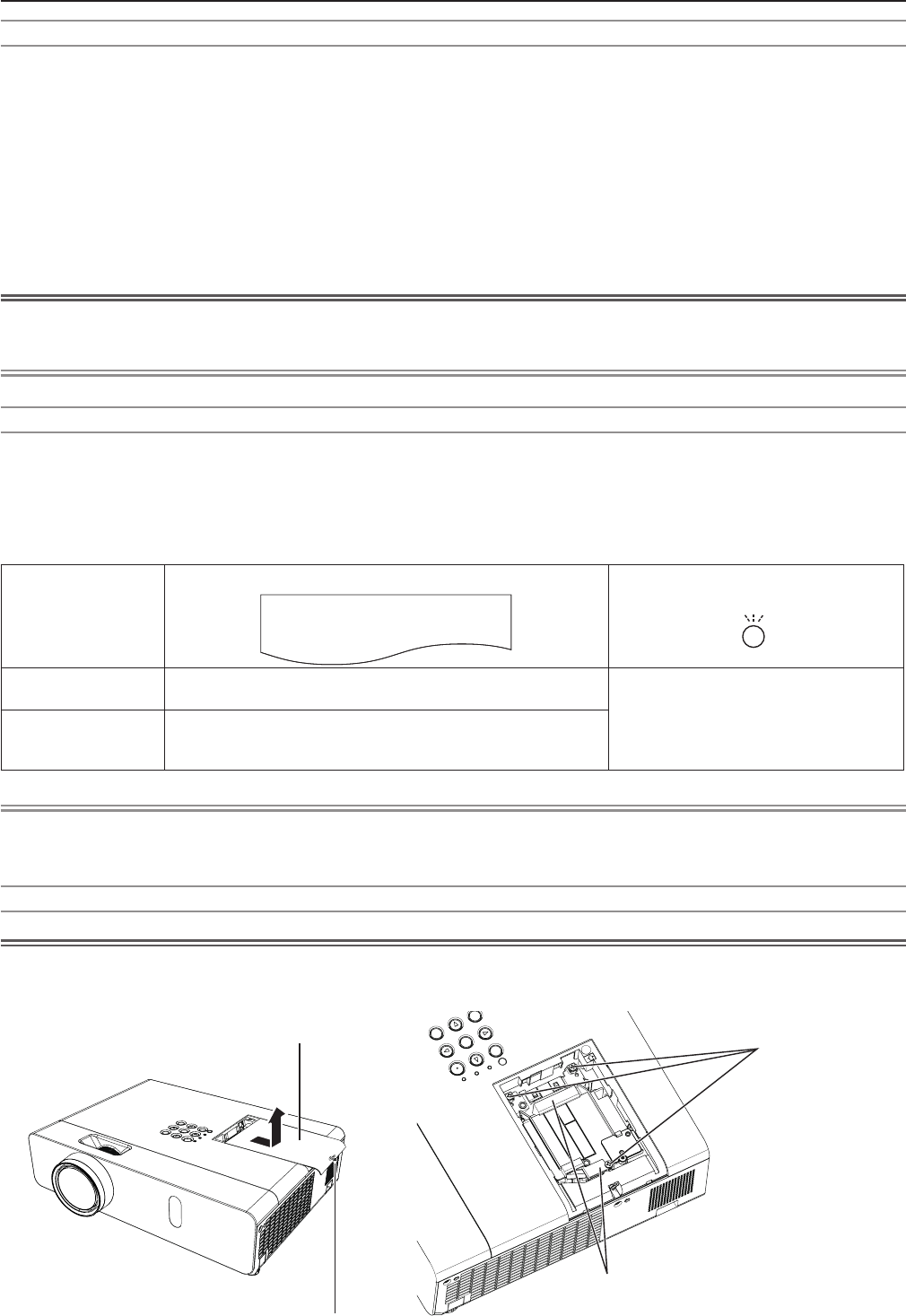
Removing the air lter unit
1) Remove the air filter cover. (Fig.1)
fOpen the air lter cover in the direction of the arrow and remove it.
2) Remove the air filter unit.
fHold the tab of the air lter unit and pull out in the direction of the arrow. (Fig.2)
fAfter removing the air lter unit, remove foreign objects and dust from the air lter compartment and the projector’s air
intake port if there are any.
Fig.1 Fig.2
Air lter cover
Air lter unit
Tab
126 - ENGLISH
Chapter 6 Maintenance - Maintenance/replacement
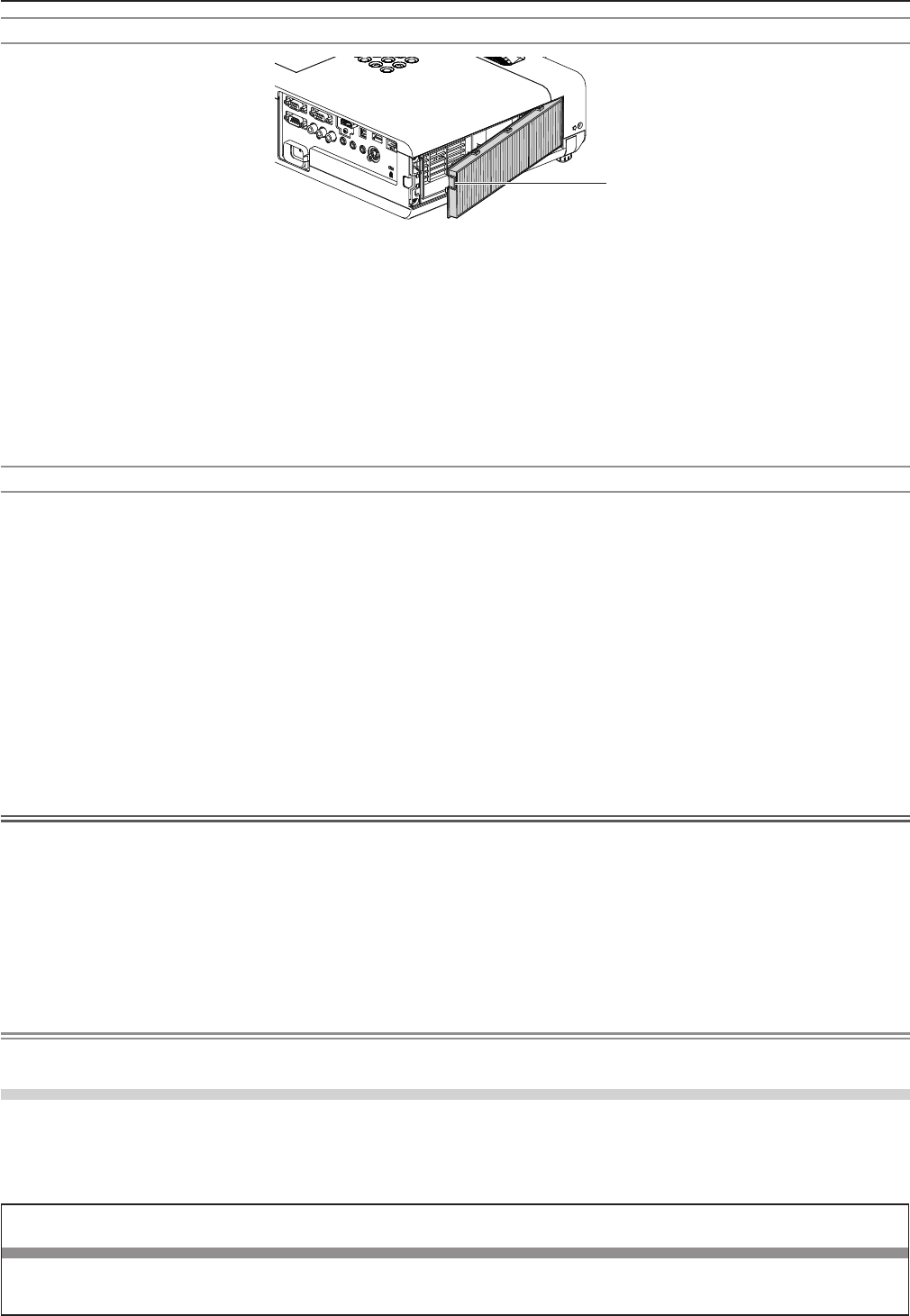
Attaching the air lter unit
Tab
1) Attach the unused air filter unit to the projector.
fHold the air lter unit that the tab is in up-left side in the gure, put the right side in the gure rst, and press the tab side
until make a click sound.
fPlease press the tab of the air lter unit other than the pleated lter during installation.
2) Install the air filter cover.
fPerform Step 1) in “Removing the air lter unit” (x page 126) in the reverse order to close the air lter cover and press
it rmly until make a click sound.
fMake sure that the air lter cover is closed tightly.
Resetting the filter counter
Be sure to reset the lter counter after replacing the air lter unit.
1) Connect the power plug, press the power <v/b> button on the control panel or the power on <b>
button on the remote control.
2) Press the <MENU> button to display the main menu, then press as to select [PROJECTOR SETUP].
3) Press the <ENTER> button, press as to select [FILTER COUNTER].
4) Press the <ENTER> button, press as to select [FILTER COUNTER RESET].
5) Press the <ENTER> button.
f[FILTER COUNTER RESET] conrmation is displayed.
6) Press qw to select [OK], then press the <ENTER> button.
fThe lter usage time is 0 after reset.
Attention
fTurn off the power before you replace the air lter unit.
fWhen attaching the air lter unit, make sure that the projector is stable, and work in an environment that is safe, even in the
event of the air lter unit dropping.
fMake sure that the air lter unit is properly attached before using the projector. If it is not attached, the projector will suck in
dirt and dust causing a malfunction.
fDo not put anything into the air vents. Doing so may result in malfunction of the projector.
fThe air lter unit to be replaced should be an unused product.
fAfter replacing the air lter, reset the lter counter. Otherwise, “FILTER COUNTER has reached the set time.” will appear on
screen.
Note
fThe replacement cycle of the air lter unit varies greatly depending on the usage environment.
Lamp unit
The lamp unit is a consumable component. Refer to “When to replace the lamp unit” (x page 128) for details about the
replacement cycle.
It is recommended to ask an authorized engineer to replace the lamp unit. Contact your dealer.
Consult your dealer to purchase a replacement lamp unit (ET-LAV300).
Warning
Do not replace the lamp unit when it is hot. (Wait at least 1 hour after use.)
The inside of the cover can become very hot, take care to avoid burn injuries.
ENGLISH - 127
Chapter 6 Maintenance - Maintenance/replacement
Notes on the replacement of the lamp unit
fThe luminous source of the lamp is made of glass and may burst if you hit it against a hard surface or drop it.
Please handle with care.
fA Phillips screwdriver is required for replacement of the lamp unit.
fWhen replacing the lamp unit, be sure to hold it by the handle.
fWhen replacing the lamp because it has stopped illuminating, there is a possibility that the lamp may be broken. If replacing
the lamp of a projector which has been installed on the ceiling, you should always assume that the lamp is broken, and you
should stand to the side of the lamp cover, not underneath it. Remove the lamp cover gently. Small pieces of glass may fall
out when the lamp cover is opened. If pieces of glass get into your eyes or mouth, seek medical advice immediately.
fThe lamp may be ruptured. Care should be taken not to scatter pieces of the broken lamp glass when replacing the lamp
unit. Pieces of the broken lamp may fall from the lamp unit especially when the projector is mounted on the ceiling, so when
replacing the lamp unit do not stand directly underneath it or position your face close to it.
fThe lamp contains mercury. Consult your local municipality or your dealer about correct disposal of used lamp units.
Attention
fPanasonic takes no responsibility for any damage or malfunction of the product resulting from use of lamp units which are
not manufactured by Panasonic. Use only specied lamp units.
Note
fThe model numbers of accessories and optional accessories are subject to change without prior notice.
When to replace the lamp unit
The lamp unit is a consumable component. Since its brightness gradually decreases over time, it is necessary to replace the
lamp unit regularly. The estimated duration before replacement is 5 000 hours, but the lamp may go off before 5 000 hours has
elapsed depending on individual lamp characteristics, usage conditions, and the installation environment. It is recommended
that the Replacement lamp unit be prepared earlier.
If you continue to use the lamp unit after 5 000 hours has elapsed, the lamp turns off automatically after approximately 10
minutes, as it will cause malfunction of the projector.
Lamp runtime
On-screen display
160 - ENGLISH
REPLACE LAMP
LAMP indicator
Over 4 800 hours The message is displayed for 30 seconds. If you press any
button within the 30 seconds, the message disappears.
Lights in red (even in stand-by mode).
Over 5 000 hours
If the power is turned on without replacing the lamp, the
power automatically turns off after approximately ten min-
utes to prevent the malfunction of the projector.
Note
fTo predict when to replace the lamp, check the lamp runtime displayed in [RUNTIME] in [STATUS] (x page 77).
f5 000 hours of use is a rough guideline, but is not a guarantee. The lamp runtime differs depending on the setting of "LAMP
POWER" menu.
Replacing the Lamp unit
Attention
fWhen the projector is mounted on a ceiling, do not work with your face close to the projector.
fDo not loosen other than designated screws.
fAttach the lamp unit and the lamp cover securely.
Lamp cover
Lamp cover
xing screw
Lamp unit xing
screws
Handles
128 - ENGLISH
Chapter 6 Maintenance - Maintenance/replacement

1) Turn off the Power by following the procedure in "Powering Off the Projector". (x page 45)
Remove the AC power plug from the wall outlet.
fWait at least 1 hour and make sure the lamp unit and surroundings are cool.
2) Use a Phillips screwdriver to loosen the lamp cover fixing screw (×1) until it turns freely and remove
the lamp cover.
fRemove the lamp cover by pulling it slowly toward the direction of the arrow.
3) Use a Phillips screwdriver to loosen the three lamp unit fixing screws (×3) until they turn freely.
4) Hold the used lamp unit by its handles, and pull it gently from the projector.
5) Insert the new lamp unit in correct direction. Tighten the three lamp unit fixing screws (×3) securely
with a Phillips screwdriver.
fWhen you experience difculty in installing the lamp unit, remove it and try again. If you use force to install the lamp
unit, the connector may be damaged.
6) Attach the lamp cover.
Tighten the lamp cover fixing screw (×1) securely with a Phillips screwdriver.
fPerform Step 2) in the reverse order to attach the lamp cover.
Note
fWhen you replace the lamp unit with new one, the projector resets the runtime of the lamp unit automatically.
ENGLISH - 129
Chapter 6 Maintenance - Maintenance/replacement

Troubleshooting
Please check following points. For details, see the corresponding pages.
Problem Cause Reference
page
Power does not turn
on.
fThe power cord may not be connected.
fNo electric supply is at the wall outlet.
fThe circuit breakers have tripped.
fIs the <LAMP> indicator or <WARNING > indicator lit or blinking?
fThe lamp cover has not been securely installed.
—
—
—
125
128
No picture appears.
fThe video signal input source may not be connected to a terminal properly.
fThe input selection setting may not be correct.
fThe [BRIGHTNESS] adjustment setting may be at the minimum setting.
fThe input source which is connected to the projector may have a problem.
fThe AV MUTE function may be in use.
38
50
61
—
53, 76
The picture is fuzzy.
fThe lens cap is still attached to the lens.
fThe lens focus may not have been set correctly.
fThe projector may not be at the correct distance from the screen.
fThe lens may be dirty.
fThe projector may be tilted too much.
23
46
33
20
—
The color is pale or
grayish.
f[COLOR] or [TINT] adjustment may be incorrect.
fThe input source which is connected to the projector may not be adjusted correctly.
fRGB cable is damaged.
61
—
—
No sound from the
internal speaker.
fThe input terminals may not have been correctly connected.
fThe volume may have been set to the minimum level.
fThe AV MUTE function may have been turned on.
fWhen the VARIABLE AUDIO OUT is plugged-in, the projector’s built-in speaker is
not available.
fThe MUTE function may have been turned on.
fIs the audio input selection in [AUDIO SETTING] set correctly?
39
49, 81
53, 76
39
54, 81
82
The remote control
does not operate.
fThe batteries may be weak.
fThe batteries may not have been inserted correctly.
fThe remote control signal receptor on the projector may be obstructed.
fThe remote control unit may be out of the operation range.
fStrong light such as uorescent shine onto the signal receptor.
fThe [REMOTE CONTROLLER] setting is set to [DISABLE] in [CONTROL DEVICE
SETUP].
fIs the ID number setting operation correct?
fCheck if the <ON/OFF> switch on the remote control is set to "ON".
—
29
26
26
26
87
54
25
Menu screen does not
appear. fIs the on-screen display function turned off (hidden)? 70
The control buttons of the
projector do not operate.
fThe [CONTROL PANEL] setting is set to [DISABLE] in [CONTROL DEVICE
SETUP]. 87
The picture does not
display correctly.
fThere may be a problem with the VCR or other signal source.
fA signal which is not compatible with the projector is being input.
—
141
Picture from a
computer does not
appear.
fThe cable may be longer than the optional cable.
fThe external video output from a laptop computer may not be correct.
—
—
Picture from a HDMI
device does not
appear or picture is
not stable.
fIs the HDMI cable securely connected?
fTurn off the power of the projector and the connected devices. Then turn the power
of the projector and the connected devices back on.
fIsn’t unsupported signal cable connected?
38, 39
—
141
No sound is output
from a HDMI device. fSet the sound channel of the attached device to Linear PCM. —
EASY SETTING
function is disabled. fTurn off and turn on the power of the projector. 83
Attention
fIf the problem persists, after conrming the contents of the table, please consult your dealer.
130 - ENGLISH
Chapter 6 Maintenance - Troubleshooting

FAQ
Please refer to the following items if you have problems with the wireless LAN connection.
The wireless LAN connection is interrupted suddenly.
fThe picture may disappear or freeze depending on the radio wave environment. In such cases, please try the following
measures.
- Please make the wireless LAN connection device close to the projector.
- Place away from devices that can emit electromagnetic radiation, such as microwave ovens, game machines. Do not use
these devices if you are still unable to solve the problem.
- If multiple wireless devices are connected with the same router, the bandwidth will be insufcient.
- Please prevent from using the projector in a location prone to static electricity, such as on a carpet.
fIf it happens that the wireless LAN connection is cut off unexpectedly, please set [WIRELESS LAN] in the [NETWORK/
USB] menu to [DISABLE], and then perform the wireless LAN connection again so that the wireless module will be
restored to the normal state.
In addition, please refer to the following items if you have problems with the MIRRORING connection.
MIRRORING cannot be connected.
fIs the [WIRELESS LAN] menu set to [DISABLE]?
fIs the input source [MIRRORING] selected correctly?
fIs [MEMORY VIEWER] or [Panasonic APPLICATION] selected in [CONNECTION LOCK] menu?
Please change the setting.
fPlease check the setting of the Intel® WiDi / Intel® Pro WiDi / Miracast compatible device. For details about the connection
method of MIRRORING, refer to the Operating Instructions of the Intel® WiDi / Intel® Pro WiDi / Miracast compatible device.
fAre there any obstacles between the Intel® WiDi / Intel® Pro WiDi / Miracast compatible device and the projector? In
addition, is the Intel® WiDi / Intel® Pro WiDi / Miracast compatible device far from the projector?
Please remove the obstacles or make the Intel® WiDi / Intel® Pro WiDi / Miracast compatible device close to the projector.
fThe column "Paired devices" will remain the connection information such as the Intel® WiDi / Intel® Pro WiDi / Miracast
compatible device etc., but you cannot reconnect with the screen, please connect with the devices that can be connected
from the list.
fCancel the sleep state or switch the log-on user of the Intel® WiDi / Intel® Pro WiDi / Miracast compatible device, the
connection may be failed.
Turn off / on the wireless LAN of the device, or turn the device and the projector off and then on again.
fIf you cannot connect to the projector, or the projector is not existed in the available connection device list, you can try to
switch the [AUTONOMOUS GROUP OWNER] menu to [OFF] or [ON].
Disconnected suddenly or Image cannot be updated.
fIf the MIRRORING idle screen is not displayed, the sound cannot be output, the connection is failed, please re-boot the
projector and then return the operation according to the following method.
- Set [STANDBY MODE] to [ECO], turn off the power, and then turn on the power. (If [STANDBY MODE] is already set to
[ECO], the procedure of the setting is not required.)
- Please turn off the power and disconnect the power plug from the power outlet.
- Please turn on the projector and the Intel® WiDi / Intel® Pro WiDi / Miracast compatible device.
The picture or sound of MIRRORING is distorted.
fSet the wireless LAN mode to [SIMPLE], [S-DIRECT] or [M-DIRECT].
fSince MIRRORING is connected wirelessly, the picture or sound may be distorted by the radio wave environment. In such
cases, please try the following measures.
- Please make the Intel® WiDi / Intel® Pro WiDi / Miracast compatible device close to the projector.
- Place away from devices that can emit electromagnetic radiation, such as microwave ovens, game machines. Do not use
these devices if you are still unable to solve the problem.
- If multiple wireless devices are connected with the same router, the bandwidth will be insufcient.
fIf there is a problem with the content itself, the picture may be distorted, please conrm the content.
fThe picture or sound of MIRRORING is distorted depending on the Intel® WiDi / Intel® Pro WiDi / Miracast compatible
device. It may be caused by the processing capability and the wireless transmission performance of the Intel® WiDi / Intel®
Pro WiDi / Miracast compatible device, and it is not a malfunction of the projector.
The connection of MIRRORING will be interrupted if there is no operation after connecting with the MIRRORING.
fDepending on the conguration of your Intel® WiDi / Intel® Pro WiDi / Miracast compatible device, the connection may be
lost in some time. Please check the saving power setting of the device.
fThe problem will be improved by updating the wireless driver and rmware. Please contact with the manufacturer for the
technical support about the device.
ENGLISH - 131
Chapter 6 Maintenance - FAQ

Others
fDepending on your Intel® WiDi / Intel® Pro WiDi / Miracast compatible device, the conrmation screen of the reconnection
that is the connection name "from UNKNOWN" will be displayed. At this time, please select "CANCEL" to cancel reconnect.
fDepending on your Intel® WiDi / Intel® Pro WiDi / Miracast compatible device, it may be required to remove the prole
during connecting. In that case, please remove the device according to the instructions.
fDepending on your Intel® WiDi / Intel® Pro WiDi / Miracast compatible Android device, when switching to Android device
during MIRRORING connecting or the conference mode, the screen that is displayed on the device may not be projected
for a while. In such a case, please wait for about ten seconds until it is projected. If it still cannot be projected, please
establish the MIRRORING connection again.
fDepending on your Intel® WiDi / Intel® Pro WiDi / Miracast compatible Android device, the sound of the device may not be
output from the projector during MIRRORING connecting. In such a case, please try the following things.
gPlease establish the MIRRORING connection again.
gThe problem may be improved by updating the rmware of the Android device. Please contact with the manufacturer for
the technical support about the device.
132 - ENGLISH
Chapter 6 Maintenance - FAQ

Chapter 7 Appendix
This chapter describes specications and after-sales service for the projector.
ENGLISH - 133

Technical Information
PJLink protocol
The network function of the projector supports PJLink class 1, and the PJLink protocol can be used to perform projector setting
and projector status query operations from a computer.
Control commands
The following table lists the PJLink protocol commands that can be used to control the projector.
fx characters in tables are non-specic characters.
Command Control details Parameter / return string Remark
POWR Power supply control 0
1
Standby
Power on
POWR ? Power supply status
query
0
1
2
3
Standby
Power on
Cool-down in progress
Warm-up in progress
INPT Input selection
11
12
21
22
31
51
RGB 1
RGB 2
VIDEO
S-VIDEO
HDMI
NETWORK/USB
INPT ? Input selection query
AVMT AV MUTE control 30
31
AV MUTE mode off
AV MUTE mode on
AVMT ? AV MUTE status query
ERST ? Error status query ××××××
1st byte Indicates fan errors,
range 0 – 2
f0 = No error
known
f1 = Warning
f2 = Error
2nd byte Indicates lamp errors,
range 0 – 2
3rd byte Indicates temperature
errors, range 0 – 2
4th byte Fixed at 0
5th byte Indicates lter errors,
range 0 – 2
6th byte Indicates other errors,
range 0 – 2
LAMP ? Lamp status query ××××××××××××
1st digits (1 – 5 digits) : Lamp cumulative operating time
2nd digit : 0 = Lamp off, 1 = Lamp on
INST ? Input selection list
query 11 12 21 22 31 51
NAME ? Projector name query ××××× Returns the name set in [NAME CHANGE] of
[NETWORK/USB].
INF1 ? Manufacturer name
query Panasonic Returns manufacturer name.
INF2 ? Model name query VW355N
VX425N Returns model name.
INF0 ? Other information query ××××× Returns information such as version number.
CLSS ? Class information query 1Returns class for PJLink.
PJLink security authorization
The password used for PJLink is the same as that of the password set for web control.
When using the projector without security authentication, do not set a password for web control.
fFor specications related to PJLink, refer to the website of Japan Business Machine and Information System Industries
Association.
URL http://pjlink.jbmia.or.jp/english/
134 - ENGLISH
Chapter 7 Appendix - Technical Information
Control commands via LAN
When WEB Control administrator rights password is set (Protect mode)
Connection method
1) Obtain the IP address and port number (Initial set value = 1 024) of the projector and make a request
for connection to the projector.
fAcquire the IP address from the menu screen of the projector, and the port number from the WEB control page.
IP address : Obtain from MAIN MENU → [NETWORK/USB] → [STATUS]
Port No. : Acquire from the WEB control → [Detailed set up] → [Port set up] page
2) There is a response from the projector.
Data section Blank Mode Blank Random number section Termination symbol
Command
example
“NTCONTROL”
(ASCII string)
‘ ’
0x20
‘1’
0x31
‘ ’
0x20
“zzzzzzzz”
(ASCII code hexadecimal
number)
(CR)
0x0d
Data
length 9 bytes 1 byte 1 byte 1 byte 8 bytes 1 byte
fMode : 1 = Protect mode
3) Generate a 32-byte hash value from the following data using MD5 algorithm.
f“xxxxxx:yyyyy:zzzzzzzz”
xxxxxx : Administrator rights user name for WEB CONTROL (Default user name is “admin1”)
yyyyy : Password of above administrator rights user (Default password is “panasonic”)
zzzzzzzz : 8-byte random number obtained in Step 2
Command transmission method
Transmit using the following command format.
rTransmitted data
Header Data section Termination symbol
Command
example
Hash value
(See above
<Connection method>)
‘0’
0x30
‘0’
0x30
Control command
(ASCII string)
(CR)
0x0d
Data length 32 bytes 1 byte 1 byte Undened length 1 byte
rReceive data
Header Data section Termination symbol
Command
example
‘0’
0x30
‘0’
0x30
Control command
(ASCII string)
(CR)
0x0d
Data length 1 byte 1 byte Undened length 1 byte
rError response
String Details Termination symbol
Message
"ERR1" Undened control command
(CR)
0x0d
"ERR2" Out of parameter range
"ERR3" Busy state or no-acceptable period
"ERR4" Timeout or no-acceptable period
"ERR5" Wrong data length
"ERRA" Password mismatch
Data length 4 bytes ― 1 byte
ENGLISH - 135
Chapter 7 Appendix - Technical Information
When WEB Control administrator rights password is not set (Non-protect mode)
Connection method
1) Obtain the IP address and port number (Initial set value = 1 024) of the projector and make a request
for connection to the projector.
fAcquire the IP address from the menu screen of the projector, and the port number from the WEB control page.
IP address : Obtain from main menu → [NETWORK/USB] → [STATUS]
Port No. : Acquire from the WEB control → [Detailed set up] → [Port set up] page
2) There is a response from the projector.
rResponse data
Data section Blank Mode Termination symbol
Command
example
“NTCONTROL”
(ASCII string)
‘ ’
0x20
‘0’
0x30
(CR)
0x0d
Data length 9 bytes 1 byte 1 byte 1 byte
fMode : 0 = Non-protect mode
Command transmission method
Transmit by the following command format.
rTransmitted data
Header Data section Termination symbol
Command
example
‘0’
0x30
‘0’
0x30
Control command
(ASCII string)
(CR)
0x0d
Data length 1 byte 1 byte Undened length 1 byte
rReceive data
Header Data section Termination symbol
Command
example
‘0’
0x30
‘0’
0x30
Control command
(ASCII string)
(CR)
0x0d
Data length 1 byte 1 byte Undened length 1 byte
rResponse data
String Details Termination symbol
Message
"ERR1" Undened control command
(CR)
0x0d
"ERR2" Out of parameter range
"ERR3" Busy state or no-acceptable period
"ERR4" Timeout or no-acceptable period
"ERR5" Wrong data length
"ERRA" Password mismatch
Data length 4 bytes ― 1 byte
136 - ENGLISH
Chapter 7 Appendix - Technical Information
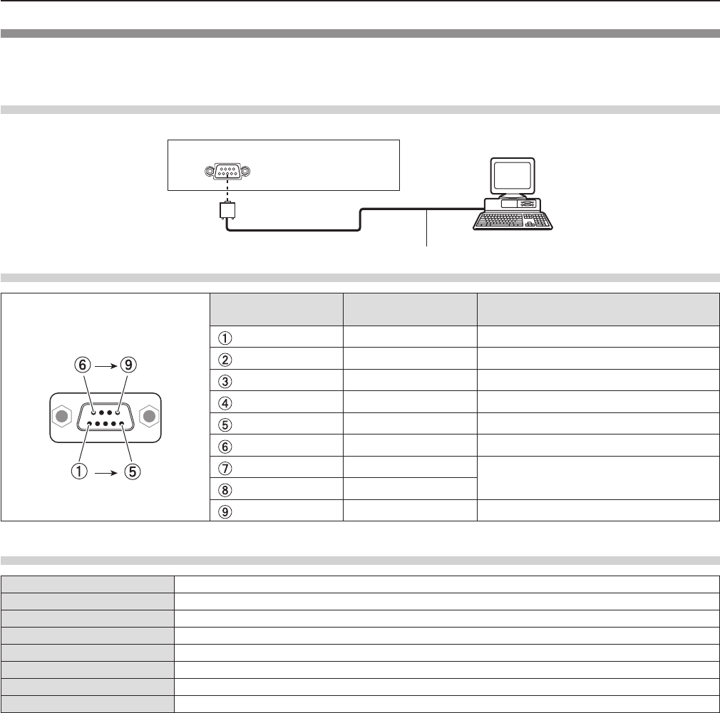
Serial terminal
The serial connector which is on the connector panel of the projector conforms to the RS-232C interface specication, so that
the projector can be controlled by a personal computer which is connected to this connector.
Connection
Connecting terminals on projector
D-Sub 9-pin (female) Computer
Communication cable (straight)
D-Sub 9-pin (male)
Pin assignments and signal names
D-Sub 9-pin (female)
Outside view Pin No. Signal name Contents
—NC
TXD Transmitted data
RXD Received data
—NC
GND Earth
—NC
CTS Connected internally
RTS
—NC
Communication conditions (Factory default)
Signal level RS-232C-compliant
Sync. method Asynchronous
Baud rate 9 600 bps
Parity None
Character length 8 bits
Stop bit 1 bit
X parameter None
S parameter None
ENGLISH - 137
Chapter 7 Appendix - Technical Information
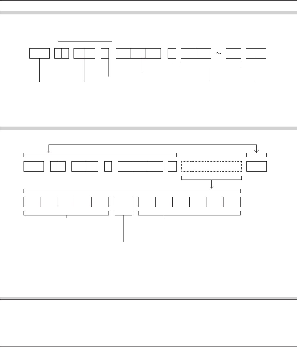
Basic format
Transmission from the computer starts with STX, then the ID, command, parameter, and ETX are sent in this order. Add
parameters according to the details of control.
STX A D I1 I2 ; C1 C2 C3 : P1 P2 Pn ETX
Basic format (with sub command)
S1 S2 S3 S4 S5 E P1 P2 P3 P4 P5 P6
STX A D I1 I2 ; C1 C2 C3 : ETX
Same as basic format
Sub command (5 bytes)
Operation (1 byte)
“=” (Value specied using parameter is set)
Parameter (6 bytes)*
Symbol “+” or “
-
” (1 byte) and set value or ad-
justment value (5 bytes)
* When transmitting a command which does not need a parameter, the operation (E) and parameter are not necessary.
Attention
fIf a command is transmitted after the lamp starts illuminating, there may be a delay in response or the command may not be
executed. Try sending or receiving any command after 60 seconds.
fWhen transmitting multiple commands, be sure to wait until 0.5 seconds has elapsed after receiving the response from the
projector before sending the next command. When transmitting a command which does not need a parameter, a colon (:) is
not necessary.
Note
fIf a command cannot be executed, the “ER401” response is sent from the projector to the computer.
fIf an invalid parameter is sent, the “ER402” response is sent from the projector to the computer.
fID transmission in RS-232C supports ZZ (ALL) and 01 to 06.
fIf a command is sent with a specied ID, a response will be sent to the computer only in the following cases.
- It matches the projector ID.
- [PROJECTOR ID] (x page 78) is set to [ALL].
fSTX and ETX are character codes. STX shown in hexadecimal is 02, and ETX shown in hexadecimal is 03.
ID designate
ZZ, 01 to 06
Start (1 byte)
(2 byte)
2 ID characters (2 bytes)
Semi-colon(1 byte)
3 command characters (3 bytes)
Colon (1 byte)
Parameter (undened length) End (1 byte)
138 - ENGLISH
Chapter 7 Appendix - Technical Information
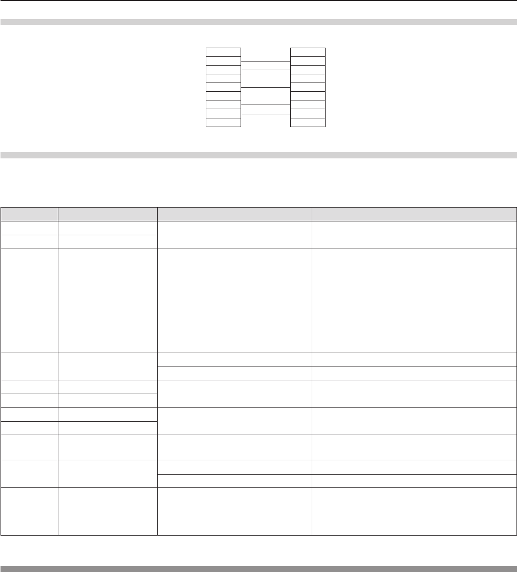
Cable specications
[When connected to a computer]
Projector
(<SERIAL IN> terminal)
1NC NC 1
Computer
(DTE specications)
2 2
3 3
4NC NC 4
5 5
6NC NC 6
7 7
8 8
9NC NC 9
Control commands
When controlling the projector from a computer, the following commands are available.
rProjector control command
Command Control contents Parameter / return string Remarks
PON Power on ―To check if the power is on, use the “Power
query” command.
POF Power off
IIS INPUT selection
VID
SVD
RG1
RG2
HD1
NWP
PA1
MC1
MV1
VIDEO
S-VIDEO
RGB1
RGB2
HDMI
NETWORK
Panasonic APPLICATION
MIRRORING
MEMORY VIEWER
OFZ Freeze 0[OFF]
1[ON]
AUU Volume up
AUD Volume down
DZU D. ZOOM up
DZD D. ZOOM down
OSH AV mute function 0
1
AV MUTE mode off
AV MUTE mode on
QPW Power query 000 Standby
001 Power on
Q$S Lamp condition query
0
1
2
3
Stand-by
Lamp ON control active
Lamp ON
Lamp OFF control active
[MENU LOCK PASSWORD] operations
To revert to the factory default password (AAAA), perform the following operations while the screen prompting input of [MENU
LOCK PASSWORD] is displayed.
1) Press the <AUTO SETUP/CANCEL> button on the remote control for at least three seconds.
2) Press s for at least three seconds.
ENGLISH - 139
Chapter 7 Appendix - Technical Information

Two window display combination list
Sub Window
COMPUTER1 COMPUTER2
HDMI VIDEO S-VIDEO
Main Window RGB YCBCR/YPBPRRGB
COMPUTER1 RGB ― ― ― l― ―
YCBCR/YPBPR― ― ― l― ―
COMPUTER2 RGB ― ― ― l― ―
HDMI l l l ―l l
VIDEO ― ― ― l― ―
S-VIDEO ― ― ― l― ―
l : Picture in Picture combinations are enabled.
―: Picture in Picture combinations are disabled.
Note
f[MEMORY VIEWER], [MIRRORING] and [Panasonic APPLICATION] do not support two window display function.
fWhen setting the movie-based signal 1080/24p, 1080/24sF,1080/25p, 1080/30p, 1080/50p or 1080/60p for HDMI input, the
two window display function will be disabled.
fThe image of the sub window picture may be distorted depending on the combination of signals.
fWhen the selected input combinations or the input signals are not correspond with the two window display, the message
"CANNOT DISPLAY THIS INPUT COMBINATION IN P IN P" will be displayed.
140 - ENGLISH
Chapter 7 Appendix - Technical Information

List of compatible signals
The following table species the type of signals compatible with the projectors.
fSymbols that indicate formats are as follows.
V = VIDEO, S = S-VIDEO, R = RGB, Y = YCBCR/YPBPR, H = HDMI
Mode Display resolution
(dots)
Scanning frequency Dot clock
frequency
(MHz)
Format*1
PnP*2
H (kHz) V (Hz) COMPUTER1/
COMPUTER2 HDMI
NTSC/NTSC4.43/
PAL-M/PAL60 720 x 480i 15.7 59.9 ― V/S ― ―
PAL/PAL-N/SECAM 720 x 576i 15.6 50.0 ― V/S ― ―
525i (480i) 720 x 480i 15.7 59.9 13.5 R/Y ― ―
625i (576i) 720 x 576i 15.6 50.0 13.5 R/Y ― ―
525i (480i) 720 (1 440) x 480i*3 15.7 59.9 27.0 H ― ―
625i (576i) 720 (1 440) x 576i*3 15.6 50.0 27.0 H ― ―
525p (480p) 720 x 483 31.5 59.9 27.0 R/Y/H ―l
625p (576p) 720 x 576 31.3 50.0 27.0 R/Y/H ―l
750 (720) /60p 1 280 x 720 45.0 60.0 74.3 R/Y/H ―l
750 (720) /50p 1 280 x 720 37.5 50.0 74.3 R/Y/H ―l
1125 (1080) /60i*4
1 920 x 1 080i
33.8 60.0 74.3 R/Y/H ―l
1125 (1080) /50i
1 920 x 1 080i
28.1 50.0 74.3 R/Y/H ―l
1125 (1080) /24p
1 920 x 1 080
27.0 24.0 74.3 R/Y/H ―l
1125 (1080) /24sF
1 920 x 1 080i
27.0 48.0 74.3 R/Y/H ― ―
1125 (1080) /25p
1 920 x 1 080
28.1 25.0 74.3 R/Y/H ― ―
1125 (1080) /30p
1 920 x 1 080
33.8 30.0 74.3 R/Y/H ― ―
1125 (1080) /60p
1 920 x 1 080
67.5 60.0 148.5 R/Y/H ―l
1125 (1080) /50p
1 920 x 1 080
56.3 50.0 148.5 R/Y/H ―l
VESA400 640 x 400 31.5 70.1 25.2 R/H ― ―
640 x 400 37.9 85.1 31.5 R/H ― ―
VGA
640 x 480 31.5 59.9 25.2 R/H l l
640 x 480 35.0 66.7 30.2 R/H l―
640 x 480 37.9 72.8 31.5 R/H l―
640 x 480 37.5 75.0 31.5 R/H l―
640 x 480 43.3 85.0 36.0 R/H ― ―
SVGA
800 x 600 35.2 56.3 36.0 R/H l―
800 x 600 37.9 60.3 40.0 R/H l l
800 x 600 48.1 72.2 50.0 R/H l―
800 x 600 46.9 75.0 49.5 R/H l―
800 x 600 53.7 85.1 56.3 R/H ― ―
MAC16 832 x 624 49.7 74.6 57.3 R/H l―
XGA
1 024 x 768 39.6 50.0 51.9 R/H ― ―
1 024 x 768 48.4 60.0 65.0 R/H l l
1 024 x 768 56.5 70.1 75.0 R/H l―
1 024 x 768 60.0 75.0 78.8 R/H l―
1 024 x 768 65.5 81.6 86.0 R/H ― ―
1 024 x 768 68.7 85.0 94.5 R/H ― ―
1 024 x 768 81.4 100.0 113.3 R/H ― ―
MXGA
1 152 x 864 64.0 70.0 94.2 R/H ― ―
1 152 x 864 67.5 75.0 108.0 R/H ― ―
1 152 x 864 77.1 85.0 119.7 R/H ― ―
MAC21 1 152 x 870 68.7 75.1 100.0 R/H ― ―
1280 x 720 1 280 x 720 37.1 50.0 60.5 R/H ― ―
1 280 x 720 44.8 60.0 74.5 R/H ― ―
1280 x 768 1 280 x 768 60.3 74.9 102.3 R/H ― ―
1 280 x 768 68.6 84.8 117.5 R/H ― ―
ENGLISH - 141
Chapter 7 Appendix - Technical Information

Mode Display resolution
(dots)
Scanning frequency Dot clock
frequency
(MHz)
Format*1
PnP*2
H (kHz) V (Hz) COMPUTER1/
COMPUTER2 HDMI
1280 x 800
1 280 x 800
41.3 50.0 68.0 R/H ― ―
1 280 x 800
49.7 59.8 83.5 R/H l l
MSXGA 1 280 x 960 60.0 60.0 108.0 R/H ― ―
SXGA
1 280 x 1 024
64.0 60.0 108.0 R/H l l
1 280 x 1 024
80.0 75.0 135.0 R/H l―
1 280 x 1 024
91.1 85.0 157.5 R/H ― ―
1366 x 768 1 366 x 768 39.6 49.9 69.0 R/H ― ―
1 366 x 768 47.7 59.8 85.5 R/H l l
SXGA+
1 400 x 1 050
65.2 60.0 122.6 R/H ― ―
1 400 x 1 050
82.3 74.9 156.0 R/H ― ―
WXGA+
1 400 x 900
*5 55.5 59.9 88.8 R/H ― ―
1600 x 900 1 600 x 900 46.3 50.0 97.0 R/H ― ―
1 600 x 900 55.9 60.0 119.0 R/H l l
UXGA
1 600 x 1 200
75.0 60.0 162.0 R/H l l
WSXGA+
1 680 x 1 050
65.2 60.0 147.1 R/H l l
1920 x 1080
1 920 x 1 080
*5 66.6 59.9 138.5 R/H ― ―
WUXGA
1 920 x 1 200
*5 74.0 60.0 154.0 R/H ― ―
*1 <COMPUTER 2 IN> terminal is only for RGB signals input.
*2 Where marked "l" signals indicates in Plug and Play is compatible with EDID of projector. Unmarked signals in Plug and
Play may also be compliant if input terminals are written in the format list. Where Plug and Play is unmarked and nothing is
written in the format list, difculties in projecting image may occur even when computer and projector appear to have same
resolution.
*3 Pixel-Repetition signal (dot clock frequency 27.0 MHz) only
*4 When a 1125 (1035)/60i signal was input, it is displayed as a 1125 (1080)/60i signal.
*5 VESA CVT-RB (Reduced Blanking)-compliant.
Note
fThe number of display dots is 1 280 x 800 for the PT-VW355N and 1 024 x 768 for the PT-VX425N.
A signal with a different resolution will be projected after converting the resolution to match the projector display.
f“i” added to the resolution value indicates an interlaced signal.
fWhen interlaced signals are connected, icker may occur on the projected image.
142 - ENGLISH
Chapter 7 Appendix - Technical Information

Glossary for network functions
Item Descriptions
Access point
These are stations for relaying electromagnetic signals between computers in a wireless
LAN. When a computer is connected to an access point, it can communicate through the
network connected to the access point.
AES
Next generation standard cryptography standardized by the National Institute of Standards
and Technology (NIST).
AES: Advanced Encryption Standard
DEFAULT GATEWAY
The devices that are used for different network standards from yours. Default Gateway
enables a connection with other network, by adjusting bilateral differences such as
communication protocols. If no gateway is specied for the IP address of access
destination, data will be sent to the host set as the default gateway.
DHCP
Abbreviation for Dynamic Host Conguration Protocol. This function automatically assigns
IP addresses to the connected equipment. If a device with the DHCP server function is
present within a LAN, it automatically assigns IP addresses to the connected equipment.
EAP
Abbreviation of PPP Extensible Authentication Protocol. An authentication protocol
extended from PPP, which is used for user authentication for remote access. MD5, TLS, S/
Key, etc. are supported as authentication methods. This protocol is adopted by the wireless
LAN authentication standard IEEE802.1X, and available methods include EAP-TLS/EAP-
TTLS/EAP-LEAP/EAP-PEAP/EAP-MD5.
EAP-FAST
Abbreviation of EAP-Flexible Authentication via Secure Tunneling. It is one of the
wireless authentication methods compatible with IEEE802.1X. It does not require digital
authentication, but establishes a tunnel for the authentication process using a secret key
cryptosystem, and authenticates the tunnel mutually to improve security. Cisco’s proprietary
method.
EAP-TTLS
Abbreviation of EAP-Tunneled Transport Layer Security. It is one of the wireless
authentication methods compatible with IEEE802.1X. It performs mutual authentication with
a digital certicate by the authentication server, and ID/password by the client. A tunnel is
established for the authentication process. Developed by Func Software in the U.S.
GTC
(EAP-GTC)
Abbreviation of EAP-Generic Token Card. It is one of the wireless authentication methods
compatible with IEEE802.1X. Authentication is performed with ID and password. Password
is acquired from a security token.
IP ADDRESS
Internet Protocol (IP) is a protocol for distributing data, and the address corresponding to
the data distribution destination is called the IP address. The same IP address cannot be
used within the same LAN.
LAN Abbreviation for Local Area Network. This is a network with a relatively narrow range such
as inside a company.
MAC Address
Each network adapter has its own ID No.
A discrete ID No. is assigned to each and every network adapter around the world. These
IDs are used to exchange data between adapters. These IDs are a combination of a
discrete number managed and assigned by the IEEE to each individual manufacturer and a
unique number assigned to each individual adapter by the manufacturer.
MD5 (EAP-MD5)
Abbreviation of EAP-Message digest algorithm 5. It is one of the wireless authentication
methods compatible with IEEE802.1X. Authentication is performed with ID and password.
Password is sent encrypted with challenge & response method.
Miracast Developed by the Wi-Fi Alliance, a standard for transmitting the screen of the device
wirelessly.
MS-CHAPv2
(EAP-MS-CHAPv2)
Abbreviation of EAP-Microsoft Challenge Handshake Authentication Protocol v2. It is one
of the wireless authentication methods compatible with IEEE802.1X.It performs mutual
authentication using a one-way encrypted password.
Open System / OPEN This is an authentication of wireless signals employing a public key encryptosystem.
PEAP
Abbreviation for EAP-Protected EAP. It is one of the wireless authentication methods
compatible with IEEE802.1X. It performs mutual authentication with a digital certicate by
the authentication server, and ID/password by the client.
ENGLISH - 143
Chapter 7 Appendix - Glossary for network functions

Item Descriptions
RADIUS server
RADIUS is an abbreviation of Remote Access Dial In User authentication Service, and
it is a protocol used for authentication in various networks such as wireless LAN. An
authentication server compatible with the protocol is called a RADIUS server.
The RADIUS server eliminates the need of registering user information separately in each
device even when there are multiple network devices, and enables integrated management
of multiple network devices and users.
Shared Key / SHARED
This is a secret key encryptosystem for wireless signals in which authentication is
performed with a key pre-set in the WEP.
Other terms for this method, in which the same key is used for both encryption and
decryption, are “shared key encryptosystem” and “common key encryptosystem”.
SSID
Abbreviation for Service Set ID. The SSID identication code must be set to distinguish
equipment included in a wireless LAN that uses access points from equipment not included
in that LAN.
This may appear as the “ESSID” or the “network name” for wireless LAN adapters made by
some manufacturers.
SUBNET MASK
This limits the range of the IP addresses assigned to computers in order to divide the
network into a number of sections during TCP/IP connection. The value used to divide the
network at this time is called the subnet mask.
TKIP
Abbreviation for Temporal Key Integrity Protocol.
This encryption protocol provides even greater security than WEP because it changes the
encryption key at xed intervals.
WEP
Abbreviation for Wired Equivalent Privacy. This is a method for encrypting communication
data. The encryption key is created and notied only to the communicating user, so the
communication data cannot be decrypted by a third party.
WPA-EAP
WPA2-EAP
Standard for the encryption method for wireless LAN. This is an encryption method for
corporations, and encryption is performed using the external server.
WPA-PSK
WPA2-PSK
This is a standard covering encryption methods used in wireless LAN.
It provides greater security than WEP, and has functions such as a user authentication
function and also TKIP (encryption protocol) which automatically changes the encryption
key at xed intervals.
And this authentication requires no authentication server.
144 - ENGLISH
Chapter 7 Appendix - Glossary for network functions
Specications
Power supply For North America: 120 V (120 V alternating current), 50 Hz/60 Hz
For other countries: 100 V - 240 V (100 V - 240 V alternating current), 50 Hz/60 Hz
Power
con-
sumption
Projecting For North America: 3.2 A, 320 W
For other countries: 3.7 A-1.5 A, 320 W
In standby mode
When [STANDBY MODE] of [ECO MANAGEMENT] is set to [ECO] : 0.5 W *1
When [STANDBY MODE] of [ECO MANAGEMENT] is set to [NETWORK] : 6 W *2
When [STANDBY MODE] of [ECO MANAGEMENT] is set to [NORMAL] : 14 W
When [STANDBY MODE] of [ECO MANAGEMENT] is set to [NORMAL], and [IN STAND-
BY MODE] of [AUDIO SETTING] is set to [ON] : 28 W
LCD
panel
Panel size PT-VW355N 1.5 cm (0.59") (aspect ratio 16 : 10)
PT-VX425N 1.6 cm (0.63") (aspect ratio 4 : 3)
Display method 3 transparent LCD panels (RGB)
Drive method Active matrix method
Pixels PT-VW355N 1 024 000 (1 280 x 800) x 3 panels
PT-VX425N 786 432 (1 024 x 768) x 3 panels
Lens Manual zoom : 1.6x
Manual focus : F 1.6 to 1.9, f 15.31 mm to 24.64 mm
Luminous lamp 240 W UHM lamp
Light output *3PT-VW355N 4 000 lm
PT-VX425N 4 500 lm
Contrast ratio *312 000 : 1 (all white / all black)
([LAMP POWER] is set to [NORMAL], meanwhile [IRIS] is set to [ON])
Appli-
cable
scanning
frequen-
cy *4
for Video signal (in-
cluding S-video)
Horizontal : 15.73 kHz, Vertical : 59.94 Hz
Horizontal : 15.63 kHz, Vertical : 50 Hz
for RGB signal Horizontal 15 kHz to 100 kHz, Vertical 50 Hz to 100 Hz
Dot clock frequency: 140 MHz or less
for YPBPR signal
[525i(480i)] Horizontal 15.73 kHz, Vertical 59.94 Hz
[625i(576i)] Horizontal 15.63 kHz, Vertical 50 Hz
[525p(480p)] Horizontal 31.47 kHz, Vertical 59.94 Hz
[625p(576p)] Horizontal 31.25 kHz, Vertical 50 Hz
[750(720)/60p] Horizontal 45.00 kHz, Vertical 60 Hz
[750(720)/50p] Horizontal 37.50 kHz, Vertical 50 Hz
[1125(1080)/60i] Horizontal 33.75 kHz, Vertical 60 Hz
[1125(1080)/50i] Horizontal 28.13 kHz, Vertical 50 Hz
[1125(1080)/60p] Horizontal 67.50 kHz, Vertical 60 Hz
[1125(1080)/50p] Horizontal 56.25 kHz, Vertical 50 Hz
[1125(1080)/24p] Horizontal 27.00 kHz, Vertical 24 Hz
[1125(1080)/24sF] Horizontal 27.00 kHz, Vertical 48 Hz
[1125(1080)/25p] Horizontal 28.13 kHz, Vertical 25 Hz
[1125(1080)/30p] Horizontal 33.75 kHz, Vertical 30 Hz
for HDMI signal
525i(480i)*5, 625i(576i)*5, 525p(480p), 625p(576p), 750(720)/60p, 750(720)/50p,
1125(1080)/24p, 1125(1080)/24sF, 1125(1080)/30p, 1125(1080)/60p, 1125(1080)/50p,
1125(1080)/60i, 1125(1080)/50i
Displayable resolution: VGA to WUXGA (non-interlace)
Dot clock frequency: up to 162 MHz
Color system 7 (NTSC, NTSC4.43, PAL, PAL-N, PAL-M, SECAM, PAL60)
Projection size 0.76 m -7.62 m (30"-300")
Screen aspect ratio PT-VW355N 16 : 10
PT-VX425N 4 : 3
Projection scheme [FRONT/DESK], [FRONT/CEILING], [REAR/DESK], [REAR/CEILING] (Menu setting
system)
Speaker 1 (4.0 cm round-type)
Maximum usable volume output 10 W
ENGLISH - 145
Chapter 7 Appendix - Specications

Termi-
nals
<COMPUTER 1 IN>
1 (High-density D-sub 15 pin female)
[RGB signal] 0.7 V [p-p] 75 Ω (When G-SYNC: 1.0 V [p-p] 75 Ω)
HD/SYNC TTL high impedance, automatic positive/negative polarity
compatible
VD TTL high impedance, automatic positive/negative polarity compatible
(SYNC/HD and VD do not support 3 value SYNC.)
[YPBPR signal] Y: 1.0 V [p-p] including synchronization signal, PBPR: 0.7 V [p-p] 75 Ω
<COMPUTER 2 IN/1
OUT>
1 (High-density D-sub 15 pin female)
[RGB signal] 0.7 V [p-p] 75 Ω (When G-SYNC: 1.0 V [p-p] 75 Ω)
HD/SYNC TTL high impedance, automatic positive/negative polarity
compatible
VD TTL high impedance, automatic positive/negative polarity compatible
(SYNC/HD and VD do not support 3 value SYNC.)
<VIDEO IN> 1 (Pin jack 1.0 V [p-p] 75 Ω)
<S-VIDEO IN> 1 (Mini DIN 4 pin, Y 1.0 V [p-p], C 0.286 V [p-p] 75 Ω, S1 signal compatible)
<HDMI IN> 1 (HDMI 19 pin, HDCP and Deep color compatible)
Audio signals: Linear PCM (Sampling frequency: 48 kHz/44.1 kHz/32 kHz)
<AUDIO IN>
2 (M3 stereo mini jack, 0.5 V [rms], input impedance 22 kΩ and more)
(<AUDIO IN 2 (MIC IN)> terminal support MIC input)
1 (Pin jack x 2 (L-R), 0.5 V [rms], input impedance 22 kΩ and more)
<VARIABLE AUDIO
OUT>
1 (M3 stereo mini jack, stereo monitor output compatible,
0 V [rms] to 2.0 V [rms] variable, output impedance 2.2 kΩ and less)
<USB A/VIEWER> USB connector (type A x 1)
<USB B/DISPLAY>
USB connector (type B x 1)
<SERIAL IN> 1 (D-sub 9 pin, RS-232C compliant, for computer control use)
<LAN> 1 (for RJ-45 network connection, PJLink compatible, 10Base-T/100Base-TX)
Wireless
LAN
Specication
standards
For North America:
IEEE802.11b/g/n : 2.412 GHz - 2.462 GHz
IEEE802.11a/n : 5.180 GHz - 5.825 GHz (except 5.600 GHz - 5.650 GHz)
For other counties:
IEEE802.11b/g/n : 2.412 GHz - 2.472 GHz
IEEE802.11a/n : 5.745 GHz - 5.805 GHz
Modulation DBPSK, DQPSK, CCK, BPSK, QPSK, 16QAM, 64QAM, MIMO
Transmission speed
IEEE 802.11b : Up to 11 Mbps
IEEE 802.11b/a : Up to 54 Mbps
IEEE 802.11n : Up to 300 Mbps
Wireless channel
For North America:
IEEE802.11b/g/n: 1~11 channel
IEEE802.11a/n: 36/40/44/48/52/56/60/64/100/104/108/112/116/132/136/140/149/153/157
/161/165 channel
For other counties:
IEEE802.11b/g/n: Passive scanning
IEEE802.11a/n: Passive scanning
Communication
distance Approx. 30 m (98'5") (depends on the usage environment)
Security
Infrastructure mode
WPA-PSK (TKIP/AES), WPA2-PSK (TKIP/AES), WEP (128 bit/64 bit),
WPA-EAP/WPA2-EAP (PEAP [MS-CHAPv2/GTC], EAP-FAST [MS-CHAPv2/GTC],
EAP-TTLS [MD5/MS-CHAPv2]
Power cable length 2.0 m (78-3/4")
Cabinet Molded plastic
Dimensions
Width: 352 mm (13-7/8")
Height: 98 mm (3-27/32") (when the adjustable feet shortened)
Depth: 279.4 mm (11")
Weight Approx. 3.4 kg (7.5 lbs.) *6
Noise level *3When set to [NORMAL] in [LAMP POWER] : 37 dB
When set to [ECO] in [LAMP POWER] : 29 dB
146 - ENGLISH
Chapter 7 Appendix - Specications
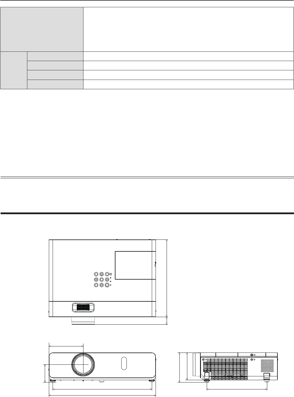
Dimensions
<Unit : mm (inch)>
113.0 (4-7/16")
255.0 (10-1/32")
352.0 (13-7/8")
24.4 (31/32")
98.0 (3-27/32")
90.0 (3-17/32")
326.0 (12-27/32") 198.0 (7-25/32")
54.8 (2-5/32")
Actual dimension may differ by product.
*1 When the [PROJECTOR SETUP] menu → [ECO MANAGEMENT] → [STANDBY MODE] is set to [ECO], the network
function (both wireless LAN and wired LAN) cannot be used in standby mode.
*2 When the [PROJECTOR SETUP] menu → [ECO MANAGEMENT] → [STANDBY MODE] is set to [NETWORK], only the
Wake on LAN function can be used in standby mode via wired LAN. When the [PROJECTOR SETUP] menu → [ECO
MANAGEMENT] → [STANDBY MODE] is set to [NETWORK], the power consumption is normally within 6 W in standby
status. If the input source was switched to [MEMORY VIEWER] or [Panasonic APPLICATION] before the projector turns
into standby, the power consumption in standby status may be more than 6 W.
*3 Measurement, measuring conditions and method of notation all comply with ISO21118 international standards.
*4 For details of video signals that can be projected using this projector, refer to “List of compatible signals”. (x page 141)
*5 Pixel-Repetition signal (dot clock frequency 27.0 MHz) only
*6 This is an average value. It may differ depending on individual product.
*7 [LAMP POWER] will be switched to [ECO] automatically when the operating environment temperature is 35 °C to 40 °C.
Note
fThe part numbers of accessories and separately sold components are subject to change without notice.
Operating environment
Operating environment temperature *7: 0 °C (32 °F) to 40 °C (104 °F)
(Elevation: below 1 400 m; [HIGH ALTITUDE MODE]: [OFF])
0 °C (32 °F) to 30 °C (86 °F)
(Elevation: 1 400 m ~ 2 000 m; [HIGH ALTITUDE MODE]: [HIGH1])
0 °C (32 °F) to 30 °C (86 °F)
(Elevation: 2 000 m ~ 2 700 m; [HIGH ALTITUDE MODE]: [HIGH2])
Operating environment humidity: 20 % to 80 % (no condensation)
Remote
control
Power supply DC 3 V (battery (AAA/R03 or AAA/LR03 Type ) x 2)
Operating range Approx. 7 m (22'11-5/8") (when operated directly in front of receptor)
Weight 102 g (3.60 ozs.) (including batteries)
Dimensions Width : 48 mm (1-7/8"), Length : 145 mm (5-23/32"), Height : 27 mm (1-1/16")
ENGLISH - 147
Chapter 7 Appendix - Specications
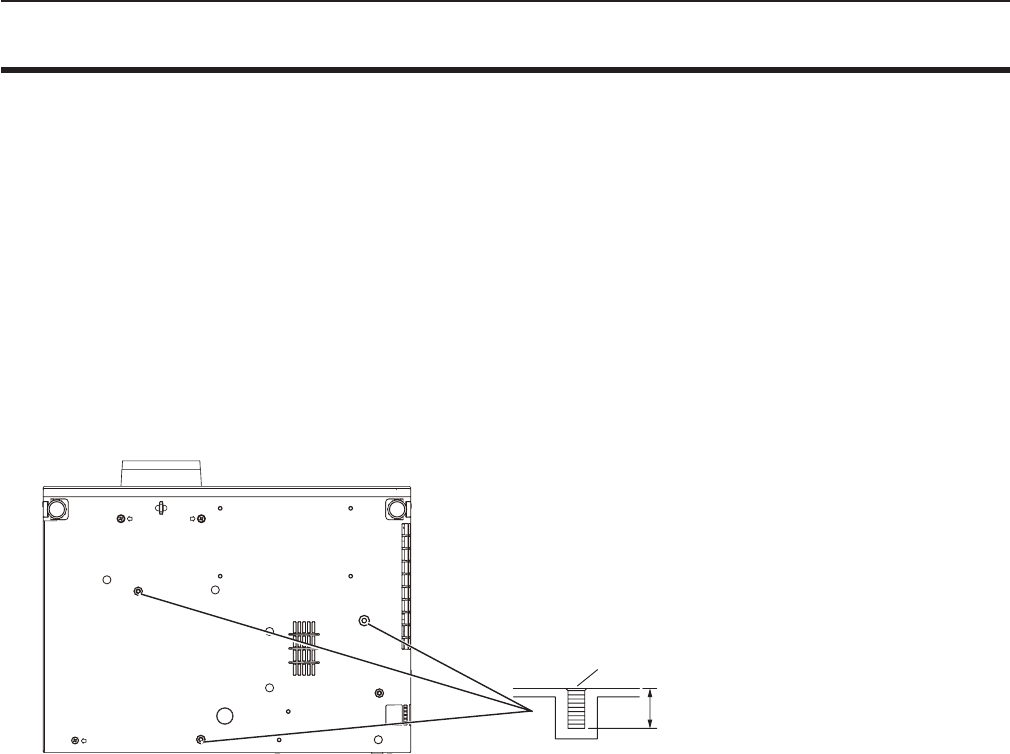
Ceiling mount bracket safeguards
fWhen installing the projector to a ceiling, be sure to use the specied optional Ceiling Mount Bracket for Projectors.
Model No. of ceiling mount bracket:
① ET-PKL100H (for high ceilings), ET-PKV400B (Projector Mount Bracket)
② ET-PKL100S (for low ceilings), ET-PKV400B (Projector Mount Bracket)
fWhen installing the projector, attach the drop-prevention kit included with the Ceiling Mount Bracket for Projectors.
fAsk a qualied technician to do the installation work such as mounting the projector on the ceiling.
fPanasonic takes no responsibility for any damage to the projector resulting from use of a ceiling mount bracket not
manufactured by Panasonic or the inappropriate choice of location for installation, even if the warranty period of the projector
has not expired.
fUnused products must be removed promptly by a qualied technician.
fUse a torque screwdriver or Allen torque wrench to tighten bolts to their specied tightening torques. Do not use electric
screwdrivers or impact screwdrivers.
fRead the Installation Instructions for the Ceiling Mount Bracket for Projectors for details.
fThe model numbers of accessories and optional accessories are subject to change without prior notice.
Bottom view
Model No. of ceiling mount bracket:
① ET-PKL100H (for high ceilings)
ET-PKV400B (Projector mount bracket)
② ET-PKL100S (for low ceilings)
ET-PKV400B (Projector mount bracket)
M4 × 0.7
8 mm (5/16")
Torque: M4 1.25 ± 0.2 N·m
148 - ENGLISH
Chapter 7 Appendix - Ceiling mount bracket safeguards

Index
A
About MIRRORING ........................123
Accessing from the Web browser ..... 99
Accessories ......................................23
<AC IN> terminal .............................. 26
Adjusting adjustable feet ..................35
[ADVANCED MENU] ........................62
[AMX D.D.] ........................................93
[ASPECT] .........................................68
Attaching the Lens Cap ....................30
[AUDIO SETTING] ............................81
<AUTO SETUP/CANCEL> button
Remote control ........................25, 49
[AUTO SETUP SETTING] ................73
<AV MUTE> button
Remote control ........................25, 53
B
[BACK COLOR] ................................ 73
Basic operations by using the remote
control ...............................................49
[BRIGHTNESS] ................................61
C
CD-ROM ...........................................24
Ceiling mount bracket safeguards .. 147
[CLOCK PHASE] .............................. 67
[CLOSED CAPTION SETTING] .......71
[COLOR] ...........................................61
[COLOR TEMPERATURE] ............... 62
<COMPUTER 1> button
Remote control ........................25, 50
<COMPUTER 2> button
Remote control ........................25, 50
[COMPUTER 2 SELECT] ................. 77
Connecting .......................................36
Connecting the power cord...............41
[CONNECTION LOCK] .....................92
[CONTRAST] ....................................60
[CONTROL DEVICE SETUP] ...........87
[Crestron Connected (TM)] ...............93
D
[DAYLIGHT VIEW] ............................63
<DEFAULT> button
Remote control ........................25, 57
Dimensions .....................................146
[DISPLAY OPTION] .......................... 70
[DOT CLOCK] ...................................67
<D.ZOOM +/-> buttons
Remote control ........................25, 52
E
<EASY SETTING/CANCEL> button
Projector body ............................... 27
[EASY SETTING] .............................83
[ECO MANAGEMENT] ..................... 79
[EMULATE] .......................................80
<ENTER> button
Projector body ............................... 27
Remote control ..............................25
F
FAQ ................................................131
[FILTER COUNTER] .........................83
[FRAME LOCK] ................................68
<FREEZE> button
Remote control ........................25, 53
<FUNCTION> button
Remote control ........................25, 50
[FUNCTION BUTTON] .....................81
G
Glossary for network functions .......142
H
<HDMI> button
Remote control ........................25, 50
[HDMI SIGNAL LEVEL] ....................71
[HIGH ALTITUDE MODE] ................. 78
I
<ID ALL> button
Remote control ........................25, 54
<ID SET> button
Remote control ........................25, 54
[INITIALIZE] ......................................96
[INITIALIZE ALL]...............................84
[INITIAL START UP] .........................78
<INPUT SELECT> button
Projector body ............................... 27
Installation mode ..............................32
[IRIS].................................................62
K
[KEYSTONE] ....................................65
<KEYSTONE> button
Remote control ........................25, 49
L
Lamp indicator .......................... 27, 125
[LAMP POWER] ...............................79
[LANGUAGE]....................................69
List of compatible signals ...............140
[LIVE MODE CUT IN] .......................93
M
Main menu ........................................57
Maintenance/replacement ..............126
[MEMORY VIEWER] ..................94, 95
<MEMORY VIEWER> button
Remote control ........................25, 50
<MENU> button
Projector body ............................... 27
Remote control ........................25, 56
[MENU LOCK] ..................................86
[MENU LOCK PASSWORD] ............86
Menu Navigation...............................56
<MIRRORING> button
Remote control ........................25, 51
[MULTI-LIVE] .................................... 94
<MUTE> button
Remote control ........................25, 54
N
[NAME CHANGE] .............................92
Network connections ........................96
[NETWORK CONTROL] ...................93
[NETWORK/USB] .............................88
[NOISE REDUCTION] ...................... 63
O
[ON-SCREEN DISPLAY] .................. 70
Optional accessories ........................24
[OTHER FUNCTIONS] ..................... 75
[OVER SCAN] ..................................67
P
<Panasonic APP> button
Remote control ........................25, 51
[PASSWORD] .............................85, 92
[PASSWORD CHANGE] ............85, 93
[PICTURE] ........................................60
[PICTURE MODE] ............................ 60
[P IN P] .............................................75
<P IN P> button
Remote control ........................25, 53
PJLink protocol ............................... 133
[POSITION] ......................................65
Power button
Projector body ............................... 27
Power indicator ...........................27, 41
Powering Off the Projector ...............45
Powering On the Projector ...............42
Power on button
Remote control ..............................25
Power standby button
Remote control ..............................25
Precautions for use...........................18
Projecting..........................................46
[PROJECTION METHOD] ................78
[PROJECTOR ID] ............................. 78
[PROJECTOR SETUP] ....................77
[P-TIMER] .........................................74
<P-TIMER> button
Remote control ........................25, 54
R
Read this rst!.....................................2
Remote control .................................25
<RETURN> button
Remote control ........................25, 57
[RGB/YPBPR] / [RGB/YCBCR] ..........64
S
[SCREEN SETTING] ........................ 72
[SECURITY] .....................................85
Setting up .........................................32
[SHARPNESS] .................................61
[SHIFT] .............................................66
[SIGNAL SEARCH] ..........................73
Specications .................................144
[STARTUP LOGO] ............................ 72
[STATUS] .................................... 77, 95
Sub-menu ......................................... 58
[SXGA MODE] ..................................73
T
[TEST PATTERN] .............................83
[TEXT CHANGE] ..............................86
[TEXT DISPLAY] ..............................86
[TINT] ................................................61
Troubleshooting ...................... 130, 131
[TV-SYSTEM] ...................................64
Two window display combination list
........................................................139
V
<VIDEO/S-VIDEO> button
Remote control ........................25, 50
W
[WIDE MODE] ..................................73
[WIRED LAN] ....................................88
[WIRELESS DETAILED SETUP] ......89
[WIRELESS LAN] ............................. 89
ENGLISH - 149
Chapter 7 Appendix - Index
M0315MZ0 -ST
Product information (for Turkey only)
AEEE Yönetmeliğine Uygundur.
Eski Ekipman ve Bataryaların İşlenmesi.
Sadece geri dönüşüm sistemleri olan Avrupa Birliği ve ülkeleri için geçerlidir.
Ürünler, ambalaj ve/veya ekli belgeler üzerindeki bu semboller kullanılmış elektrik ve elektronik
ürünlerin ve pillerin genel ev atığı ile karıştırılmaması gerektiğini ifade eder.
Eski ürünlerin ve pillerin toplanması ve geri kazanılması için bu atıkları lütfen yasayla belirlenmiş
olan uygun toplama merkezlerine teslim ediniz.
Bu atıkların doğru işlenmesiyle, değerli kaynakların korunmasına ve insan sağlığı ve çevreye
olası negatif etkilerinin engellenmesine yardımcı olabilirsiniz.
Atıkların toplanması ve geri dönüşümü için detaylı bilgi için lütfen bağlı olduğunuz yerel
yönetimlerle iletişime geçiniz.
Atıkların atılmasıyla ilgili yanlış uygulamalar yasayla belirlenmiş olan cezalara sebebiyet verebilir.
Information for Users on Collection and Disposal of Old Equipment and used Batteries
These symbols on the products, packaging, and/or accompanying documents mean that used
electrical and electronic products and batteries should not be mixed with general household
waste. For proper treatment, recovery and recycling of old products and used batteries, please
take them to applicable collection points, in accordance with your national legislation and the
Directives 2002/96/EC and 2006/66/EC.
By disposing of these products and batteries correctly, you will help to save valuable resources
and prevent any potential negative effects on human health and the environment which could
otherwise arise from inappropriate waste handling.
For more information about collection and recycling of old products and batteries, please contact
your local municipality, your waste disposal service or the point of sale where you purchased the
items.
Penalties may be applicable for incorrect disposal of this waste, in accordance with national
legislation.
For business users in the European Union
If you wish to discard electrical and electronic equipment, please contact your dealer or supplier
for further information.
Information on Disposal in other Countries outside the European Union
These symbols are only valid in the European Union. If you wish to discard these items, please
contact your local authorities or dealer and ask for the correct method of disposal.
Note for the battery symbol (bottom two symbol examples):
This symbol might be used in combination with a chemical symbol. In this case it complies with
the requirement set by the Directive for the chemical involved.
Panasonic Corporation
Web Site : http://panasonic.net/avc/projector/
© Panasonic Corporation 2015
Panasonic Systems Communications Company of North America
5th Floor, Two Riverfront Plaza, Newark, NJ 07102-5490
5770 Ambler Drive, Mississauga, Ontario L4W 2T3
TEL: (877) 803 - 8492
TEL: (905) 624 - 5010
Panasonic Canada Inc.