Panasonic of North America PT-VW355N LCD PROJECTOR User Manual PT VW355N Part 1
Panasonic Corporation of North America LCD PROJECTOR PT VW355N Part 1
Contents
- 1. PT-VW355N_User Manual Part 1
- 2. PT-VW355N_User Manual Part 2
- 3. PT-VW355N_User Manual Part 3
- 4. PT-VW355N_User Manual Part 4
PT-VW355N_User Manual Part 1
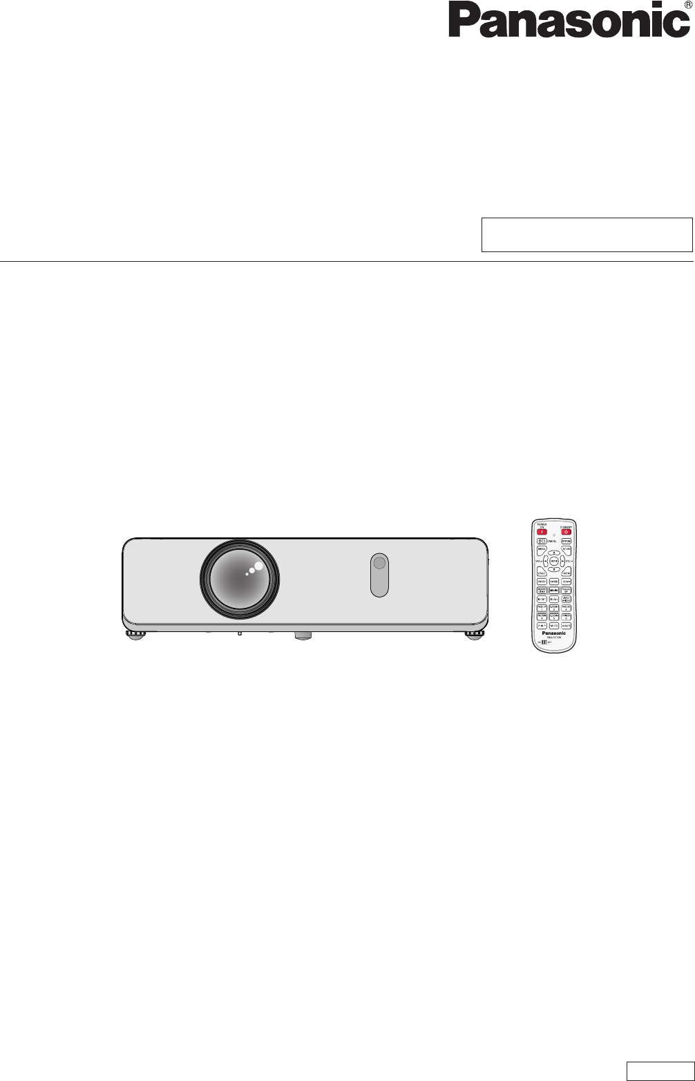
Thank you for purchasing this Panasonic Product.
■ Before operating this product, please read the instructions carefully, and save this manual
for future use.
■ Before using your projector, be sure to read “Read this rst!” (x pages 2 to 12).
LCD Projector Commercial Use
Operating Instructions
Functional Manual
TQBJ0854
ENGLISH
Model No.
PT-VW355N
PT-VX425N
Read this rst!
Read this rst!
WARNING: THIS APPARATUS MUST BE EARTHED.
WARNING: To prevent damage which may result in re or shock hazard, do not expose this appliance to rain
or moisture.
This device is not intended for use in the direct eld of view at visual display workplaces. To avoid
incommoding reexions at visual display workplaces this device must not be placed in the direct
eld of view.
The equipment is not intended for used at a video workstation in compliance BildscharbV.
The sound pressure level at the operator position is equal or less than 70 dB (A) according to ISO 7779.
WARNING:
1. Remove the plug from the mains socket when this unit is not in use for a prolonged period of time.
2. To prevent electric shock, do not remove cover. No user serviceable parts inside. Refer servicing to qualied
service personnel.
3. Do not remove the earthing pin on the mains plug. This apparatus is equipped with a three prong earthing
type mains plug. This plug will only t an earthing-type mains socket. This is a safety feature. If you are un-
able to insert the plug into the mains socket, contact an electrician. Do not defeat the purpose of the earthing
plug.
WARNING: TO REDUCE THE RISK OF FIRE OR ELECTRIC SHOCK, DO NOT EXPOSE THIS PRODUCT
TO RAIN OR MOISTURE.
oThe lightning ash with arrowhead symbol, within an equilateral triangle, is intended to alert the
user to the presence of uninsulated “dangerous voltage” within the product’s enclosure that may
be of sufcient magnitude to constitute a risk of electric shock to persons.
7The exclamation point within an equilateral triangle is intended to alert the user to the presence of
important operating and maintenance (servicing) instructions in the literature accompanying the
product.
WARNING: TURN THE POWER OFF AND DISCONNECT THE POWER PLUG FROM THE WALL OUTLET
BEFORE REPLACING THE LAMP UNIT.
CAUTION: To assure continued compliance, follow the attached installation instructions. This includes using
the provided power cord and shielded interface cables when connecting to computer or peripheral
devices. Also, any unauthorized changes or modications to this equipment could void the user's
authority to operate this device.
This is a device to project images onto a screen, etc., and is not intended for use as indoor lighting in a
domestic environment.
Directive 2009/125/EC
2 - ENGLISH
Read this rst!
Importer's name and address within the European Union
Panasonic Marketing Europe GmbH
Panasonic Testing Centre
Winsbergring 15, 22525 Hamburg, Germany
CAUTION (North/Middle/South America)
CAUTION: This equipment is equipped with a three-pin grounding-type power
plug. Do not remove the grounding pin on the power plug. This plug
will only t a grounding-type power outlet. This is a safety feature. If
you are unable to insert the plug into the outlet, contact an electrician.
Do not defeat the purpose of the grounding plug. Do not remove
FCC NOTICE (USA)
Declaration of Conformity
Model Number: PT-VW355N, PT-VX425N
Trade Name: Panasonic
Responsible Party: Panasonic Corporation of North America
Address: Two Riverfront Plaza, Newark, NJ 07102-5490
General Contact: http://www.panasonic.com/support
Projector Contact: http://www.panasonic.net/avc/projector
This device complies with Part 15 of the FCC Rules.
Operation is subject to the following two conditions: (1) This device may not cause harmful interference, and (2)
this device must accept any interference received, including interference that may cause undesired operation.
To assure continued compliance, follow the attached installation instructions and do not make any unauthorized
modications.
CAUTION:
This equipment has been tested and found to comply with the limits for a Class B digital device, pursuant
to Part 15 of the FCC Rules. These limits are designed to provide reasonable protection against harmful
interference in a residential installation. This equipment generates, uses and can radiate radio frequency
energy and, if not installed and used in accordance with the instructions, may cause harmful interference to
radio communications. However, there is no guarantee that interference will not occur in a particular installation.
If this equipment does cause harmful interference to radio or television reception, which can be determined
by turning the equipment off and on, the user is encouraged to try to correct the interference by one of the
following measures:
fReorient or relocate the receiving antenna.
fIncrease the separation between the equipment and receiver.
fConnect the equipment into an outlet on a circuit different from that to which the receiver is connected.
fConsult the dealer or an experienced radio/BD technician for help.
Any changes or modications not expressly approved by Panasonic Corp. of North America could void the
user’s authority to operate this device.
This device is restricted to indoor use when operated in the 5.15 to 5.25 GHz frequency range.
The user may nd the booklet “Something About Interference” available from FCC local regional ofces helpful.
FCC Warning:
To assure continued FCC emission limit compliance, follow the attached installation instructions. This includes
using the provided power cord and shielded interface cables when connecting to computer or peripheral
devices. Also, any unauthorized changes or modications to this equipment could void the user’s authority to
operate this device.
ENGLISH - 3

Read this rst!
FCC NOTICE (USA AND CANADA)
This device complies with Part 15 of FCC Rules and RSS-Gen of IC Rules.
Operation is subject to the following two conditions:
(1) This device may not cause harmful interference, and (2) this device must accept any interference received,
including interference that may cause undesired operation of this device.
This transmitter must not be co-located or operated in conjunction with any other antenna or transmitter.
This equipment has been approved for mobile operation and requires minimum 20 cm spacing be provided
between antennas and all person’s body (excluding extremities of hands, wrist and feet) during wireless modes
of operation.
This product is restricted to indoor use due to its operation in the 5.15 to 5.25 GHz frequency range.
FCC and IC require this product to be used indoors for the frequency range 5.15 to 5.25 GHz to reduce the
potential for harmful interference to co-channel Mobile Satellite systems. High power radars are allocated
as primary users of the 5.25 to 5.35 GHz and 5.65 to 5.85 GHz bands. These radar stations can cause
interference with and/or damage this product.
The available scientic evidence does not show that any health problems are associated with using low power
wireless devices.
There is no proof, however, that these low power wireless devices are absolutely safe. Low power Wireless
devices emit low levels of radio frequency energy (RF) in the microwave range while being used.
Whereas high levels of RF can produce health effects (by heating tissue), exposure to low-level RF that does
not produce heating effects causes no known adverse health effects.
Many studies of low-level RF exposures have not found any biological effects. Some studies have suggested
that some biological effects might occur, but such ndings have not been conrmed by additional research.
Wireless LAN adaptor has been tested and found to comply with FCC/IC radiation exposure limits set forth for
an uncontrolled equipment and meets the FCC radio frequency (RF) Exposure Guidelines in Supplement C to
OET65 and RSS-102 of the IC radio frequency (RF) Exposure rules.
WARNING:
• Not for use in a computer room as dened in the Standard for the Protection of Electronic Computer/Data
Processing Equipment, ANSI/NFPA 75.
• For permanently connected equipment, a readily accessible disconnect device shall be incorporated in the
building installation wiring.
• For pluggable equipment, the socket-outlet shall be installed near the equipment and shall be easily
accessible.
Product Identication Marking is located on the bottom of the Wireless LAN Adaptor.
Federal Communication Commission (FCC) / IC Radiation Exposure Statement
This EUT is compliance with SAR for general population/uncontrolled exposure limits in ANSI/IEEE C95.1-
1999/IC RSS-102 and had been tested in accordance with the measurement methods and procedures specied
in OET Bulletin 65 Supplement C/IEEE 1528. This equipment should be installed and operated with minimum
distance 0.5 cm between the radiator & your body.
4 - ENGLISH
Read this rst!
CAUTION:
Be aware of the following limits before using the Wireless LAN Module.
• To use the Wireless LAN Module, an access point needs to be obtained.
• Do not use the Wireless LAN Module to connect to any wireless network (SSID*) for which you do not have
usage rights. Such networks may be listed as a result of searches. However, using them may be regarded
as illegal access.
*SSID is a name for identifying a particular wireless network for transmission.
• Do not subject the Wireless LAN Module to high temperatures, direct sunlight or moisture.
• Do not bend, or subject the Wireless LAN Module to strong impacts.
• Do not disassemble or alter the Wireless LAN Module in any way.
• Do not attempt to install the Wireless LAN Module in any incompatible device.
• Do not remove the Wireless LAN Module from the host product during operations.
•Data transmitted and received over radio waves may be intercepted and monitored.
•To avoid malfunctions caused by radio wave interface, keep the host product away from the devices such as
other wireless LAN devices, microwaves and the devices that use 2.4 GHz and 5 GHz signals when using
the Wireless LAN Module.
• When noises occur due to the static electricity, etc., the projector might stop operating for the protection of
the devices. In this case, turn the projector Off and disconnect the power plug from the wall outlet, then turn
it On again.
• Depending on the area, this Wireless LAN Module may not be available.
NOTIFICATION (Canada)
This class B digital apparatus complies with Canadian ICES-003.
Notice (USA only):
• This product has a High Intensity Discharge (HID) lamp that contains mercury. Disposal may be regulated
in your community due to environmental considerations. For disposal or recycling information, please visit
Panasonic website: http://www.panasonic.com/environmental or call 1-888-769-0149.
Notice (Singapore only):
• Complies with IDA Standards ID : DB102345
Notice (UAE only):
•This equipment has been registered with the Telecommunications Regulatory Authority for use in the UAE.
TRA
REGISTERED No: ER0119239/13
DEALER No: DA0081667/12
ENGLISH - 5
Read this rst!
IMPORTANT: THE MOULDED PLUG (U.K. only)
FOR YOUR SAFETY, PLEASE READ THE FOLLOWING TEXT CAREFULLY.
This appliance is supplied with a moulded three pin mains plug for your safety and convenience. A 13 amp fuse is tted in
this plug. Should the fuse need to be replaced, please ensure that the replacement fuse has a rating of 13 amps and that it
is approved by ASTA or BSI to BS1362.
Check for the ASTA mark or the BSI mark on the body of the fuse.
If the plug contains a removable fuse cover, you must ensure that it is retted when the fuse is replaced. If you lose the fuse
cover, the plug must not be used until a replacement cover is obtained. A replacement fuse cover can be purchased from an
Authorised Service Center.
If the tted moulded plug is unsuitable for the mains socket in your home, then the fuse should be removed and the plug cut
off and disposed of safely. There is a danger of severe electrical shock if the cut off plug is inserted into any 13 amp socket.
If a new plug is to be tted, please observe the wiring code as shown below.
If in any doubt, please consult a qualied electrician.
WARNING: THIS APPLIANCE MUST BE EARTHED.
IMPORTANT: The wires in this mains lead are coloured in accordance with the following code:
Green - and - Yellow: Earth
Blue: Neutral
Brown: Live
As the colours of the wire in the mains lead of this appliance may not correspond with the coloured markings
identifying the terminals in your plug, proceed as follows.
The wire which is coloured GREEN - AND - YELLOW must be connected to the terminal in the
plug which is marked with the letter E or by the Earth symbol or coloured GREEN or GREEN -
AND - YELLOW.
The wire which is coloured BLUE must be connected to the terminal in the plug which is marked
with the letter N or coloured BLACK.
The wire which is coloured BROWN must be connected to the terminal in the plug which is marked
with the letter L or coloured RED.
How to replace the fuse: Open the fuse compartment with a screwdriver and replace the fuse.
13A250V BS1363/A
HE-8
N
ASA
L
6 - ENGLISH
Read this rst!
Brazil Only
Brasil Apenas
Manuseio de baterias usadas
BRASIL
Após o uso, as pilhas e /ou baterias deverão
ser entregues ao estabelecimento comercial
ou rede de assistência técnica autorizada.
Cobrir os terminais positivo (+) e negativo (-) com uma ta isolante adesiva, antes de depositar numa caixa
destinada para o recolhimento. O contato entre partes metálicas pode causar vazamentos,
gerar calor, romper a blindagem e produzir fogo. (Fig. 1)
Fig. 1
Como isolar os terminais
Não desmonte, não remova o invólucro, nem amasse a bateria. O gás liberado pela bateria pode irritar a
garganta, danicar o lacre do invólucro ou o vazamento provocar calor, ruptura da blindagem e produzir fogo
devido ao curto circuito dos terminais. Não incinere nem aqueça as baterias, elas não podem car expostas a
temperaturas superiores a 100 °C (212 °F). O gás liberado pela bateria pode irritar a garganta, danicar o lacre
do invólucro ou o vazamento provocar calor, ruptura da blindagem e produzir fogo devido ao curto circuito dos
terminais provocado internamente.
Evite o contato com o liquido que vazar das baterias. Caso isto ocorra, lave bem a parte afetada com bastante
água. Caso haja irritação, consulte um médico.
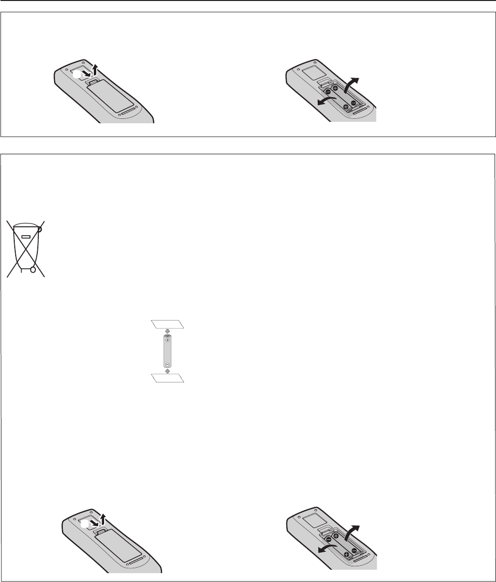
Remoção das baterias
1. Pressione a guia e levante a tampa. 2. Remova as baterias.
(ii)
(i)
(ii)
(i)
Fita Isolante
Fita Isolante
To remove the battery
1. Press the guide and lift the cover. 2. Remove the batteries.
(ii)
(i)
(ii)
(i)
ENGLISH - 7

Read this rst!
WARNING:
POWER
The wall outlet shall be installed near the equipment and shall be easily accessible when problems oc-
cur. If the following problems occur, disconnect the power plug from the wall outlet immediately.
Continued use of the projector in these conditions will result in re or electric shock.
zIf foreign objects or water get inside the projector, disconnect the power plug from the wall outlet.
zIf the projector is dropped or the cabinet is broken, disconnect the power plug from the wall outlet.
zIf you notice smoke, strange smells or noise coming from the projector, disconnect the power plug from the
wall outlet.
zYou have to disconnect the power plug from the wall outlet to cut off the power supply.
Please contact an Authorized Service Center for repairs, and do not attempt to repair the projector yourself.
During a thunderstorm, do not touch the projector or the cable.
Electric shocks can result.
Do not do anything that might damage the power cord or the power plug.
If the power cord is used while damaged, electric shocks, short-circuits or re will result.
zDo not damage the power cord, make any modications to it, place it near any hot objects, bend it
excessively, twist it, pull it, place heavy objects on top of it or wrap it into a bundle.
Ask an Authorized Service Center to carry out any repairs to the power cord that might be necessary.
Completely insert the power plug into the wall outlet and the power connector into the projector
terminal.
If the plug is not inserted correctly, electric shocks or overheating will result.
zDo not use plugs which are damaged or wall outlets which are coming loose from the wall.
Do not use anything other than the provided power cord.
Failure to observe this will result in re or electric shocks. Please note that if you do not use the provided power
cord to ground the device on the side of the outlet, this may result in electric shocks.
Clean the power plug regularly to prevent it from becoming covered in dust.
Failure to observe this will cause a re.
zIf dust builds up on the power plug, the resulting humidity can damage the insulation.
zIf not using the projector for an extended period of time, pull the power plug out from the wall outlet.
Pull the power plug out from the wall outlet and wipe it with a dry cloth regularly.
Do not handle the power plug and power connector with wet hands.
Failure to observe this will result in electric shocks.
Do not overload the wall outlet.
If the power supply is overloaded (ex., by using too many adapters), overheating may occur and re will result.
ON USE/INSTALLATION
Do not place the projector on soft materials such as carpets or sponge mats.
Doing so will cause the projector to overheat, which can cause burns, re or damage to the projector.
Do not set up the projector in humid or dusty places or in places where the projector may come into
contact with oily smoke or steam, ex. a bathroom.
Using the projector under such conditions will result in re, electric shocks or components deterioration. Com-
ponents deterioration (such as ceiling mount brackets) may cause the projector which is mounted on the ceiling
to fall down.
Do not install this projector in a place which is not strong enough to take the full weight of the projec-
tor or on top of a surface which is sloped or unstable.
Failure to observe this will cause projector to fall down or tip over the projector, and severe injury or damage
could result.
Installation work (such as ceiling mount bracket) should only be carried out by a qualied technician.
If installation is not carried out and secured correctly, it can cause injury or accidents, such as electric shocks.
zBe sure to use the wire provided with the ceiling mount bracket as an extra safety measure to prevent the
projector from falling down. (Install in a different location to the ceiling mount bracket.)
Do not cover the air intake/exhaust ports.
Doing so will cause the projector to overheat, which can cause re or damage to the projector.
zDo not place the projector in narrow, badly ventilated places.
zDo not place the projector on cloth or papers, as these materials could be drawn into the air intake port.
zProvide at least 1 m (40") of space between any walls or objects and the exhaust port, and at least 50 cm
(20") of space between any walls or objects and the intake port.
8 - ENGLISH

Read this rst!
WARNING:
Do not place your hands or other objects close to the air exhaust port.
Doing so will cause burns or damage your hands or other objects.
zHeated air comes out of the air exhaust port. Do not place your hands or face, or objects which cannot
withstand heat close to this port.
Do not look at or place your skin into the lights emitted from the lens while the projector is being used.
Doing so can cause burns or loss of sight.
zStrong light is emitted from the projector’s lens. Do not look at or place your hands directly into this light.
zBe especially careful not to let young children look into the lens. In addition, turn off the power and discon-
nect the power plug when you are away from the projector.
Never attempt to remodel or disassemble the projector.
High voltages can cause re or electric shocks.
zFor any inspection, adjustment and repair work, please contact an Authorized Service Center.
Do not allow metal objects, ammable objects, or liquids to enter inside of the projector. Do not allow
the projector to get wet.
Doing so may cause short circuits or overheating, and result in re, electric shock, or malfunction of the projec-
tor.
zDo not place containers of liquid or metal objects near the projector.
zIf liquid enters inside of the projector, consult your dealer.
zParticular attention must be paid to children.
Use the ceiling mount bracket specied by Panasonic.
Using the ceiling mount bracket other than the specied one will result in falling accidents.
zAttach the supplied safety cable to the ceiling mount bracket to prevent the projector from falling down.
ACCESSORIES
Do not use or handle the batteries improperly, and refer to the following.
Failure to observe this will cause burns, batteries to leak, overheat, explode or catch re.
zDo not use unspecied batteries.
zDo not use chargeable batteries.
zDo not disassemble dry cell batteries.
zDo not heat the batteries or place them into water or re.
zDo not allow the + and
-
terminals of the batteries to come into contact with metallic objects such as neck-
laces or hairpins.
zDo not store or carry batteries together with metallic objects.
zStore the batteries in a plastic bag and keep them away from metallic objects.
zMake sure the polarities (+ and
-
) are correct when inserting the batteries.
zDo not use a new battery together with an old battery or mix different types of batteries.
zDo not use batteries with the outer cover peeling away or removed.
Do not allow children to reach the batteries.
Accidentally swallowing them can cause physical harm.
zIf swallowed, seek medical advice immediately.
If the battery uid leaks, do not touch it with bare hands, and take the following measures if necessary.
zBattery uid on your skin or clothing could result in skin inammation or injury.
Rinse with clean water and seek medical advice immediately.
zBattery uid coming in contact with your eyes could result in loss of sight.
In this case, do not rub your eyes. Rinse with clean water and seek medical advice immediately.
Do not disassemble the lamp unit.
If the lamp breaks, it could cause injury.
Lamp replacement
The lamp has high internal pressure. If improperly handled, an explosion and severe injury or accidents will
result.
zThe lamp can easily explode if struck against hard objects or dropped.
zBefore replacing the lamp unit, be sure to turn the power off and to disconnect the power plug from the wall
outlet.
Electric shocks or explosions can result if this is not done.
zWhen replacing the lamp unit, turn the power off and allow the lamp to cool for at least 1 hour before han-
dling it otherwise it can cause burns.
Do not use the supplied power cord with devices other than this projector.
zUsing the supplied power cord with devices other than this projector may cause short circuits or overheat-
ing, and result in electric shock or re.
Remove the depleted batteries from the remote control promptly.
zLeaving them in the unit may result in uid leakage, overheating, or explosion of the batteries.
ENGLISH - 9

Read this rst!
CAUTION:
POWER
When disconnecting the power cord, be sure to hold the power plug and power connector.
If the power cord itself is pulled, the lead will become damaged, and re, short-circuits or serious electric
shocks will result.
When not using the projector for an extended period of time, disconnect the power plug from the wall
outlet.
Failure to do so may result in re or electric shock.
Disconnect the power plug from the wall outlet before carrying out any cleaning and replacing the unit.
Failure to do so may result in electric shock.
ON USE/INSTALLATION
Do not place heavy objects on top of the projector.
Failure to observe this will cause the projector to become unbalanced and fall, which could result in damage or
injury. The projector will be damaged or deformed.
Do not put your weight on this projector.
You could fall or the projector could break, and injury will result.
zBe especially careful not to let young children stand or sit on the projector.
Do not place the projector in extremely hot locations.
Doing so will cause the outer casing or internal components to deteriorate, or result in re.
zTake particular care in locations exposed to direct sunlight or near stoves.
Do not place the projector where it may be affected by salt or corrosive gas.
Doing so may cause the projector to become faulty due to corrosion.
Do not place objects in front of the lens while the projector is being used.
Doing so can cause re or damage to the object and can cause the projector to malfunction.
zExtremely strong light is emitted from the projector’s lens.
Do not stand in front of the lens while the projector is being used.
Doing so can cause damage and burns to clothing.
zExtremely strong light is emitted from the projector’s lens.
Always disconnect all cables before moving the projector.
Moving the projector with cables still attached can damage the cables, which will cause re or electric shocks to
occur.
When mounting the projector on the ceiling, keep mounting screws and power cord from contact with
metal parts inside the ceiling.
Contact with metal parts inside the ceiling can cause electric shocks.
Never plug headphones and earphones into <VARIABLE AUDIO OUT> terminal.
Excessive sound pressure from earphones and headphones can cause hearing loss.
ACCESSORIES
Do not use the old lamp unit.
If used it could cause lamp explosion.
If the lamp has broken, ventilate the room immediately. Do not touch or bring your face close to the
broken pieces.
Failure to observe this will cause the user to absorb the gas which was released when the lamp broke and which
contains nearly the same amount of mercury as uorescent lamp, and the broken pieces will cause injury.
zIf you believe that you have absorbed the gas or that the gas has got into your eyes or mouth, seek medical
advice immediately.
zAsk your dealer about replacing the lamp unit and check the inside of the projector.
When not using the projector for an extended period of time, remove the batteries from the remote
control.
Failure to observe this will cause the batteries to leak, overheat, catch re or explode, which may result in re or
contamination of surrounding area.
MAINTENANCE
Ask your dealer about cleaning inside the projector once a year.
Continuous use while dust is accumulated inside the projector may result in re.
zFor cleaning fee, ask your dealer.
10 - ENGLISH
Read this rst!
Declaration of Conformity
Declaration of Conformity (DoC)
This equipment is in compliance with the essential requirements and other relevant provisions of Directive 1999/5/EC.
Customers can download a copy of the original DoC for this product from our DoC server: http://www.ptc.panasonic.de
Contact in the EU: Panasonic Marketing Europe GmbH, Panasonic Testing Centre, Winsbergring 15, 22525 Hamburg, Germany
This product is intended to be used in the following countries.
Austria, Belgium, Bulgaria, Czech, Cyprus, Denmark, Estonia, Finland, France, Germany, Greece, Hungary, Iceland, Ireland, Italy, Latvia,
Lithuania, Luxembourg, Malta, Netherlands, Norway, Poland, Portugal, Romania, Slovenia, Slovak, Spain, Sweden, Switzerland, UK &
Croatia
Konformitätserklärung (KE)
Dieses Gerät entspricht den grundlegenden Anforderungen und den weiteren entsprechenden Vorgaben der Richtlinie 1999/5/EU.
Kunden können eine Kopie der Original-KE für dieses Produkt von unserem KE-Server herunterladen: http://www.ptc.panasonic.de
Kontaktadresse in der EG: Panasonic Marketing Europe GmbH, Panasonic Testing Centre, Winsbergring 15, 22525 Hamburg, Germany
Dieses Produkt ist für den Einsatz in den folgenden Ländern vorgesehen.
Österreich, Belgien, Bulgarien, Tschechische Republik, Zypern, Dänemark, Estland, Finnland, Frankreich, Deutschland, Griechenland,
Ungarn, Island, Irland, Italien, Lettland, Litauen, Luxemburg, Malta, Niederlande, Norwegen, Polen, Portugal, Rumänien, Slowenien,
Slowakei, Spanien, Schweden, Schweiz, Großbritannien und Kroatie
Déclaration de Conformité (DC)
Cet appareil est conforme aux exigences essentielles et aux autres dispositions pertinentes de la Directive 1999/5/EC.
Les clients peuvent télécharger une copie de la DC originale pour ce produit à partir de notre serveur DC: http://www.ptc.panasonic.de
Coordonnées dans l’UE : Panasonic Marketing Europe GmbH, Panasonic Testing Centre, Winsbergring 15, 22525 Hamburg, Germany
Ce produit est conçu pour l’utilisation dans les pays suivants.
Autriche, Belgique, Bulgarie, République Tchéquie, Chypre, Danemark, Estonie, Finlande, France, Allemagne, Grèce, Hongrie, Islande,
Irlande, Italie, Lettonie, Lituanie, Luxembourg, Malte, Pays-Bas, Norvège, Pologne, Portugal, Roumanie, Slovénie, Slovaquie, Espagne,
Suède, Suisse, Royaume-Uni et Croatie
Declaración de conformidad (DC)
Este equipo cumple con los requisitos esenciales asi como con otras disposiciones de la Directiva 1999/5/CE.
El cliente puede descargar una copia de la DC original de este producto desde nuestro servidor DC: http://www.ptc.panasonic.de
Contacto en la U.E.: Panasonic Marketing Europe GmbH, Panasonic Testing Centre, Winsbergring 15, 22525 Hamburg, Germany
Este producto ha sido desarrollado para el uso en los siguientes países.
Austria, Bélgica, Bulgaria, República Checa, Chipre, Dinamarca, Estonia, Finlandia, Francia, Alemania, Grecia, Hungría, Islandia, Irlanda,
Italia, Letonia, Lituania, Luxemburgo, Malta, Holanda, Noruega, Polonia, Portugal, Rumania, Eslovenia, Eslovaquia, España, Suecia,
Suiza, el Reino Unido y Croacia
Dichiarazione di conformità (DoC)
Questo apparato é conforme ai requisiti essenziali ed agli altri principi sanciti dalla Direttiva 1999/5/CE.
I clienti possono scaricare la copia del DoC originale per questo prodotto dal nostro server DoC: http://www.ptc.panasonic.de
Contatto nella EU: Panasonic Marketing Europe GmbH, Panasonic Testing Centre, Winsbergring 15, 22525 Hamburg, Germany
I prodotti sono stati prodotti per l’uso nei seguenti paesi.
Austria, Belgio, Bulgaria, Repubblica Ceca, Cipro, Danimarca, Estonia, Finlandia, Francia, Germania, Grecia, Irlanda, Islanda, Italia,
Lettonia, Lituania, Lussembugo, Malta, Olanda, Norvegia, Polonia, Portogallo, Romania, Regno Unito, Slovenia, Slovacchia, Spagna,
Svezia, Svizzera, Ungheria, Croazia
ENGLISH - 11
Read this rst!
Important Safety Notice
ENGLISH - 5
Important
Information
12 - ENGLISH

rTrademarks, etc.
fWindows, Windows Vista, Internet Explorer and PowerPoint are registered trademarks or trademarks of Microsoft
Corporation in the United States and other countries.
fMac, Mac OS, OS X, iPad, iPhone, iPod touch and Safari are trademarks of Apple Inc., registered in the United States and
other countries.
fHDMI, the HDMI logo and High-Denition Multimedia Interface is a trademark or registered trademark of HDMI
Licensing LLC.
fPJLink™ is a trademark or pending trademark in Japan, the United States, and other countries and regions.
fRoomView, Crestron RoomView are registered trademarks of Crestron Electronics, Inc.
Crestron Connected™ and Fusion RV are trademarks of Crestron Electronics, Inc.
fAdobe, Adobe Flash Player and Adobe Reader are trademarks or registered trademarks of Adobe Systems Inc. in the United
States and/or other countries.
fIntel® is a trademark of Intel Corporation in the U.S. and/or other countries.
fSome of the fonts used in the on-screen menu are Ricoh bitmap fonts, which are manufactured and sold by Ricoh Company,
Ltd.
fWi-Fi®, Wi-Fi DirectTM and MiracastTM are registered trademarks or trademarks of Wi-Fi Alliance.
fAndroid is a trademark of Google Inc.
fiOS is a trademark and registered trademark of Cisco in the United States and other countries and is used under license.
fThis product is licensed under the AVC Patent Portfolio License, VC-1 Patent Portfolio License and MPEG-4 Visual Patent
Portfolio License for the personal use of a consumer or other uses in which it does not receive remuneration to (i) encode
video in compliance with the AVC Standard, VC-1 Standard and MPEG-4 Visual Standard (“AVC/VC-1/MPEG-4 Video”)
and/or (ii) decode AVC/VC-1/MPEG-4 Video that was encoded by a consumer engaged in a personal activity and/or was
obtained from a video provider licensed to provide AVC/VC-1/MPEG-4 Video. No license is granted or shall be implied for
any other use.
Additional information may be obtained from MPEG LA, LLC. See http://www.mpegla.com
fOther names, company names or product names used in these operating instructions are the trademarks or registered
trademarks of their respective holders.
Please note that the operating instructions do not include the ® and ™ symbols.
Software information regarding this product
This product incorporates the following software.
(1) The software which is developed independently by or for Panasonic Corporation
(2) The software owned by third party and licensed to Panasonic Corporation
(3) The software which is licensed under the GNU GENERAL PUBLIC LICENSE Version2.0 (GPL V2.0)
(4) The software which is licensed under the GNU LESSER GENERAL PUBLIC LICENSE Version2.1 (LGPL V2.1)
(5) Open source software which is not licensed under the GPL V2.0 and LGPL V2.1
The software categorized as (3) ~ (5), the license is available in accordance with gnu general public license and gnu lesser
general public license respectively, it is distributed in the hope that it will be useful, but without any warranty, without even
the implied warranty of merchantability or tness for a particular purpose. As for the terms and conditions, please refer to the
software license of the supplied CD-ROM.
If you wish to ask any questions as to the software, please contact (sav.pj.gpl.pavc@ml.jp.panasonic.com) by email.
rIllustrations in these operating instructions
fNote that illustrations of the projector and screens may differ from the ones you actually see.
rPage references
fReference pages in this manual are indicated as: (x page 00).
rTerm
fIn this manual, the “Wireless remote control unit” accessory is referred to as the “Remote control”.
ENGLISH - 13
Features of the Projector
High Contrast
▶A high contrast of 12 000:1 is achieved by
the unique optical system.
Easy Setting Function
▶This projector is installed with a camera,
[FOCUS ASSIST], [SCREEN FIT] and
[COLORBOARD] will be adjusted in order
when you press the <EASY SETTING>
button on the control panel.
▶The position of image will be corrected
automatically when you press the
<AUTO SETUP> button on the remote
control.
Wireless Projection Function
▶This function allows you to output video
and audio from multiple computers by
using the application software "Wireless
Manager ME6.3".
▶By using the MIRRORING function, the
images displayed on the Intel® WiDi / Intel®
Pro WiDi / Miracast compatible device can
be projected through the wireless LAN
connection.
Useful Functions for Presentations
▶Memory viewer function allows you to
project video and still images which are
stored in USB memory without using
computer.
▶Connect the projector to a computer with
a USB cable, the USB display function of
the application software "Wireless Manager
ME6.3" allows you to output video and
audio.
Quick Steps
For details, see the corresponding pages.
1. Set up your projector.
(x page 32)
2. Connect with other devices.
(Æ page 35)
3. Connect the power cord.
(x page 41)
4. Power on.
(x page 42)
5. Make initial settings.
(x page 42)
fTake this step when you power on for the rst time after
purchasing the projector.
6. Select the input signal.
(x page 46)
7. Adjust the image.
(x page 46)
14 - ENGLISH

Contents
Contents
Read this first! ............................................2
Declaration of Conformity ......................................11
Chapter 1 Preparation
Precautions for use ................................................. 18
Cautions when transporting .................................. 18
Cautions when installing ....................................... 18
Security ................................................................ 19
Disposal ................................................................ 20
Cautions on use ................................................... 20
Notes on Using Wireless Connection ................... 21
Accessories .......................................................... 23
Contents of the supplied CD-ROM ....................... 24
Optional accessories ............................................ 24
About your projector ............................................... 25
Remote control ..................................................... 25
Projector body ...................................................... 26
Preparing the remote control ................................. 29
Inserting and removing batteries .......................... 29
When using the system with multiple projectors .. 29
Attaching the Lens Cap .......................................... 30
Chapter 2 Getting Started
Setting up ................................................................. 32
Installation mode .................................................. 32
Parts for ceiling mount (optional) .......................... 32
Screen size and throw distance ........................... 33
Adjusting adjustable feet ...................................... 35
Connecting ............................................................... 36
Before connecting ................................................ 36
Connecting example : AV equipment ................... 38
Connecting example : Computers ........................ 38
Connecting example : Audio ................................. 39
Chapter 3 Basic Operations
Powering on/off ....................................................... 41
Connecting the power cord .................................. 41
Power indicator ..................................................... 41
Powering On the Projector ................................... 42
When the initial setting screen is displayed .......... 42
Making adjustments and selections ..................... 44
Powering Off the Projector ................................... 45
Direct Power Off function ..................................... 45
Projecting ................................................................. 46
Selecting the input signal ..................................... 46
How to adjust the state of the image .................... 46
Adjusting the projected image via EASY
SETTING function ............................................. 47
Basic operations by using the remote control ..... 49
Using the AUTO SETUP function ......................... 49
Using the KEYSTONE button ............................... 49
Controlling the volume of the speaker .................. 49
Using the FUNCTION button ................................ 50
Switching the input signal ..................................... 50
Using the MEMORY VIEWER function ................ 50
Using the MIRRORING function ........................... 51
Using the Panasonic APPLICATION function ...... 51
Using the PAGE UP/PAGE DOWN buttons .......... 51
Using the DIGITAL ZOOM function ...................... 52
Using the FREEZE function ................................. 53
Using the AV MUTE function ................................ 53
Using the P IN P function ..................................... 53
Using the P-TIMER function ................................. 54
Using the MUTE function ..................................... 54
Setting the ID number of the remote control ........ 54
Chapter 4 Settings
Menu Navigation ...................................................... 56
Navigating through the menu ............................... 56
Resetting adjustment values to the factory default 5 7
Main menu ............................................................ 57
Sub-menu ............................................................. 58
[PICTURE] menu ...................................................... 60
[PICTURE MODE] ................................................ 60
[CONTRAST] ........................................................ 60
[BRIGHTNESS] .................................................... 61
[COLOR] ............................................................... 61
[TINT] ................................................................... 61
[SHARPNESS] ..................................................... 61
[COLOR TEMPERATURE] ................................... 62
[IRIS] .................................................................... 62
[ADVANCED MENU] ............................................ 62
[DAYLIGHT VIEW] ................................................ 63
[DIGITAL CINEMA REALITY] ............................... 63
[NOISE REDUCTION] .......................................... 63
[TV-SYSTEM] ....................................................... 64
[RGB/YPBPR] / [RGB/YCBCR] .............................. 64
[POSITION] menu .................................................... 65
[KEYSTONE] ........................................................ 65
[SHIFT] ................................................................. 66
[DOT CLOCK]....................................................... 67
[CLOCK PHASE] .................................................. 67
[OVER SCAN] ...................................................... 67
[ASPECT] ............................................................. 68
[FRAME LOCK] .................................................... 68
[LANGUAGE] menu ................................................. 69
[LANGUAGE] ....................................................... 69
[DISPLAY OPTION] menu ....................................... 70
[ON-SCREEN DISPLAY] ...................................... 70
[HDMI SIGNAL LEVEL] ........................................ 71
[CLOSED CAPTION SETTING] ........................... 71
[SCREEN SETTING] ........................................... 72
ENGLISH - 15
Contents
Be sure to read “Read this rst!” from page 2.

[STARTUP LOGO] ................................................ 72
[AUTO SETUP SETTING] .................................... 73
[SIGNAL SEARCH] .............................................. 73
[BACK COLOR] .................................................... 73
[WIDE MODE] ...................................................... 73
[SXGA MODE] ...................................................... 73
[P-TIMER] ............................................................. 74
[P IN P] ................................................................. 75
[OTHER FUNCTIONS] ......................................... 75
[PROJECTOR SETUP] menu .................................. 77
[STATUS] .............................................................. 77
[COMPUTER2 SELECT] ...................................... 77
[PROJECTOR ID] ................................................. 78
[INITIAL START UP] ............................................. 78
[PROJECTION METHOD] .................................... 78
[HIGH ALTITUDE MODE] ..................................... 78
[LAMP POWER] ................................................... 79
[ECO MANAGEMENT] ......................................... 79
[EMULATE] ........................................................... 80
[FUNCTION BUTTON] ......................................... 81
[AUDIO SETTING] ............................................... 81
[EASY SETTING] ................................................. 83
[TEST PATTERN] ................................................. 83
[FILTER COUNTER]............................................. 83
[INITIALIZE ALL] .................................................. 84
[SECURITY] menu ................................................... 85
[PASSWORD] ....................................................... 85
[PASSWORD CHANGE] ...................................... 85
[TEXT DISPLAY] .................................................. 86
[TEXT CHANGE] .................................................. 86
[MENU LOCK] ...................................................... 86
[MENU LOCK PASSWORD] ................................ 86
[CONTROL DEVICE SETUP] ............................... 87
[NETWORK/USB] menu .......................................... 88
Conrmation of the network information ............... 88
[WIRED LAN] ....................................................... 88
[WIRELESS LAN] ................................................. 89
[CONNECTION LOCK] ........................................ 92
[NAME CHANGE] ................................................. 92
[PASSWORD] ....................................................... 92
[PASSWORD CHANGE] ...................................... 93
[NETWORK CONTROL] ...................................... 93
[AMX D.D.] ........................................................... 93
[Crestron Connected(TM)] .................................... 93
[LIVE MODE CUT IN] ........................................... 93
[MULTI-LIVE] ........................................................ 94
[MEMORY VIEWER] ............................................ 94
[MIRRORING] ...................................................... 95
[STATUS] .............................................................. 95
[INITIALIZE] .......................................................... 96
Network connections ............................................ 96
Accessing from the web browser ......................... 99
Chapter 5 Operation of Function
Memory Viewer function ....................................... 116
What you can project with the Memory Viewer
function .............................................................116
Cautions on using USB Memory .........................116
Operations of the Memory Viewer screen ...........117
Playing the still image ..........................................119
Playing the video ................................................ 120
About MIRRORING ................................................ 123
Chapter 6 Maintenance
Lamp and Warning Indicators .............................. 125
When an indicator lights up ................................ 125
Maintenance/replacement..................................... 126
Before performing maintenance/replacement .... 126
Maintenance ....................................................... 126
Replacing the unit ............................................... 126
Troubleshooting .................................................... 130
FAQ ......................................................................... 131
Chapter 7 Appendix
Technical Information ........................................... 134
PJLink protocol ................................................... 134
Control commands via LAN ................................ 135
Serial terminal .................................................... 137
[MENU LOCK PASSWORD] operations ............ 139
Two window display combination list .................. 140
List of compatible signals ................................... 141
Glossary for network functions ........................... 143
Specications ........................................................ 145
Dimensions ............................................................ 147
Ceiling mount bracket safeguards....................... 148
Index ....................................................................... 149
16 - ENGLISH
Contents

Chapter 1 Preparation
This chapter describes things you need to know or check before using the projector.
ENGLISH - 17
Precautions for use
Cautions when transporting
fWhen transporting the projector, hold it securely by its bottom and avoid excessive vibration and impacts. Doing so may
damage the internal parts and result in malfunctions.
fDo not transport the projector with the adjustable feet extended. Doing so may damage the adjustable feet.
Cautions when installing
rDo not set up the projector outdoors.
fThe projector is designed for indoor use only.
rDo not use under the following conditions.
fPlaces where vibration and impacts occur such as in a car or vehicle: Doing so may damage the internal parts and result in
malfunctions.
fLocations near the sea or areas affected by corrosive gas: Corrosion may damage internal components or cause the
projector to malfunction.
fNear the exhaust of an air conditioner: Depending on the conditions of use, the screen may uctuate in rare cases due
to the heated air from the air exhaust port or the hot or cooled air. Make sure that the exhaust from the projector or other
equipment, or the air from the air conditioner does not blow toward the front of the projector.
fPlaces with sharp temperature uctuations such as near lights (studio lamp): Doing so may shorten the life of the lamp, or
result in deformation of the outer case due to heat, which may cause malfunctions.
The operating environment temperature of the projector should be between 0 °C (32 °F) and 40 °C (104 °F)*1 when using it
at elevations lower than 1 400 m (4 593') above sea level, and between 0 °C (32 °F) and 30 °C (86 °F) when using it at high
altitudes (between 1 400 m (4 593') and 2 700 m (8 858') above sea level).
*1 When the operating environment temperature of the projector is between 35 °C (95°F) and 40 °C (104 °F), the lamp mode
will change to [ECO] automatically.
fNear high-voltage power lines or near motors: Doing so may interfere with the operation of the projector.
rBe sure to ask a specialized technician when installing the product to a ceiling.
This requires an optional ceiling mount bracket. Be sure to use the Projector Mount Bracket together with the ceiling mount
bracket for high ceilings or low ceilings.
Model No.:
① ET-PKL100H (for high ceilings), ET-PKV400B (Projector Mount Bracket)
② ET-PKL100S (for low ceilings), ET-PKV400B (Projector Mount Bracket)
rFocus adjustment
The projection lens is thermally affected by the light from the light source, making the focus unstable in the period just after
switching on the power. It is recommended that the images are projected continuously for at least 30 minutes before the focus
is adjusted.
rWhen using the projector in the elevation of below 1 400 m (4 593'), make sure [HIGH ALTITUDE MODE]
is set to [OFF].
Failure to do so may shorten the life of the internal parts and result in malfunctions.
rWhen using the projector in the elevation of above 1 400 m (4 593') and below 2 000 m (6 562'), make
sure [HIGH ALTITUDE MODE] is set to [HIGH1].
Failure to do so may shorten the life of the internal parts and result in malfunctions.
rWhen using the projector in the elevation of above 2 000 m (6 562') and below 2 700 m (8 858'), make
sure [HIGH ALTITUDE MODE] is set to [HIGH2].
Failure to do so may shorten the life of the internal parts and result in malfunctions.
rDo not install the projector at elevations of 2 700 m (8 858') or higher above sea level.
Failure to do so may shorten the life of the internal parts and result in malfunctions.
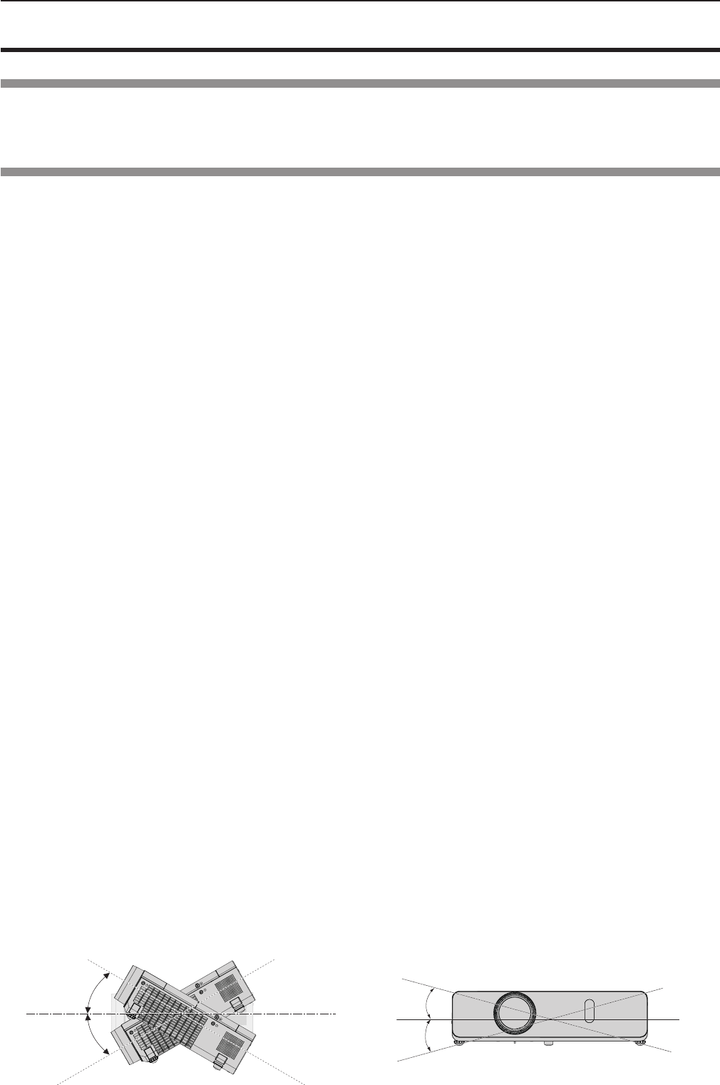
rDo not tilt the projector or place it on its side.
Do not tilt the projector body more than approximately ±40 degrees vertically or ±15 degrees horizontally. Over tilting may
result in shortening the life of the components.
Within 40°
Within 40°
Within 15°
Within 15°
18 - ENGLISH
Chapter 1 Preparation - Precautions for use
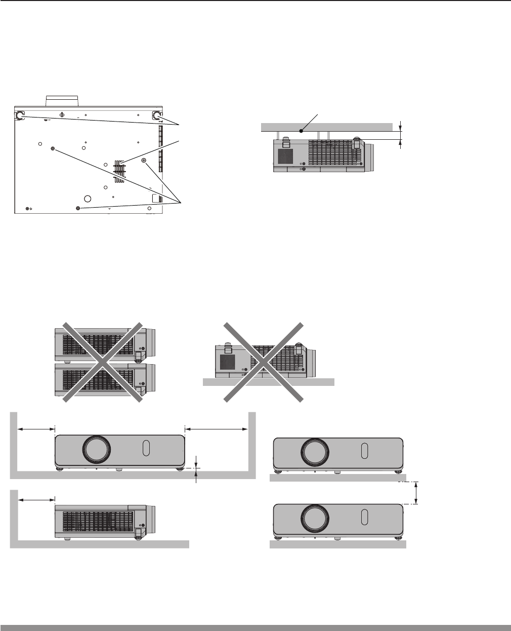
rCautions when setting the projectors
fIf you want to use the projector other than the way of setting on the desk/oor with the adjustable feet or mounting on the
ceiling, use the three screw holes for ceiling mounting (as shown below) to x the projector.
(Screw: M4; Depth of the screw hole: 8 mm (5/16"); Torque: M4 1.25 ± 0.2 N·m)
In addition, always keep a gap of more than 20 mm (25/32") between the bottom of the projector and installation surface.
Make sure that there is no clearance of at least 20 mm (25/32″) between the screw holes for ceiling mounting and the
installation surface by inserting supports (metallic) between them.
fDo not stack the projectors.
fDo not use the projector supporting it by the top.
fDo not block the ventilation ports (intake and exhaust) of the projector.
fAvoid heating and cooling air from the air conditioning system directly blow to the ventilation ports (intake and exhaust) of
the projector.
fDo not install the projector in a conned space.
When placing the projector in a conned space, a ventilation and/or air conditioning system is required. Exhaust heat may
accumulate when the ventilation is not enough, triggering the protection circuit of the projector.
Security
Take safety measures against following incidents.
fPersonal information being leaked via this product.
fUnauthorized operation of this product by a malicious third party.
fInterfering or stopping of this product by a malicious third party.
Security instruction (x pages 85, 92, 110)
fMake your password as difcult to guess as possible.
fChange your password periodically.
fPanasonic or its afliate company never inquires a password directly to a customer. Do not tell your password in case you
receive such an inquiry.
fThe connecting network must be secured by rewall or others.
fSet a password for web control and restrict the users who can log in.
The positions of adjustable feet and the
screw holes for ceiling mounting
Adjustable feet Over 20 mm
(25/32”)
Installation surface
Screw holes for
ceiling mounting
fMake sure the air ow into the air intake
port (bottom), failure to do so may cause the
projector cannot work.
Air intake port
(bottom)
500 mm (19-11/16")
or longer
1 000 mm
(39-3/8") or longer
7 mm (9/32")
or longer
500 mm (19-11/16")
or longer 200 mm (7-7/8")
or longer
ENGLISH - 19
Chapter 1 Preparation - Precautions for use

Disposal
To dispose of the product, ask your local authorities or dealer for correct methods of disposal.
The lamp contains mercury. When disposing of used lamp units, contact your local authorities or dealer for correct methods of
disposal.
Cautions on use
rTo get a good picture quality
fIn order to view a beautiful image in higher contrast, prepare an appropriate environment. Draw curtains or blinds over
windows and turn off any lights near the screen to prevent outside light or light from indoor lamp from shining onto the
screen.
rDo not touch the surface of the projector lens with your bare hands.
If the surface of the projection lens becomes dirty from ngerprints or anything else, this will be magnied and projected onto
the screen.
Attach the supplied lens cap to the projection lens when you do not use the projector.
rLCD panel
The LCD panel is precision-made. Note that in rare cases, pixels of high precision could be missing or always lit. Note that
such phenomena do not indicate malfunction. If still images are projected for a long time, a residual image may remain on the
LCD panel. Note that the residual image may not disappear.
rOptical parts
When the operating environment temperature is high or in environments where lots of dust, cigarette smoke, etc. is present,
the replacement cycle of the LCD panel, polarizing plate and other optical parts may be shorter even if used for less than one
year. Consult your dealer for details.
rLamp
The luminous source of the projector is a mercury lamp with high internal pressure.
A high-pressure mercury lamp has the following characteristics.
fThe luminance of the lamp will decrease by duration of usage.
fThe lamp may burst with a loud sound or have its service life shortened because of shock, chipping, or degradation due to
cumulative runtime.
fThe life of the lamp varies greatly depending on individual specicities and usage conditions. In particular, continuous use
over 12 hours and frequent switching off/on of the power greatly deteriorate the lamp and affect the lamp life.
fIn rare cases, the lamp burst shortly after the projection.
fThe risk of bursting increases when the lamp is used beyond its replacement cycle. Make sure to replace the lamp unit
consistently. (“When to replace the lamp unit” (x page 128), "Replacing the Lamp unit" (x page 128))
fIf the lamp bursts, gas contained inside of the lamp is released in a form of smoke.
fIt is recommended to store replacement lamp for contingency.
rComputer and external device connections
fWhen connecting a computer or an external device, read this manual carefully regarding the use of power cords and
shielded cables as well.
20 - ENGLISH
Chapter 1 Preparation - Precautions for use
Notes on Using Wireless Connection
Wireless connection function of the projector uses radio waves in the 2.4 GHz / 5 GHz band.
A radio station license is not required, but be sure to read and fully understand the following items before use.
rDo not use near other wireless equipment.
The following equipment may use radio waves in the same band as the projector.
When the projector is used near these devices, radio wave interference may make communication impossible, or the
communication speed may become slower.
fMicrowave ovens, etc.
fIndustrial, chemical and medical equipment, etc.
fIn-plant radio stations for identifying moving objects such as those used in factory manufacturing lines, etc.
fDesignated low-power radio stations
r If at all possible, avoid the use of cellular phones, TV sets or radios near the projector.
Cellular phones, TV sets, radios and similar devices use different radio bands from the projector, so there is no effect on
wireless communication or the transmission and reception of these devices. However, radio waves from the projector may
produce audio or video noise.
r Wireless communication radio waves cannot penetrate steel reinforcements, metal, concrete, etc.
Communication is possible through walls and oors made from materials such as wood and glass (except
glass containing
wire mesh), but not through walls and oors made from steel reinforcements, metal, concrete, etc.
r Avoid using the projector in locations prone to static electricity.
If the projector is used in a location prone to static electricity, such as on a carpet, the wireless LAN or wired LAN
connection may be lost.
If the static electricity or noise make it impossible to establish a connection with the LAN, please press the power button on
the remote control or the control panel to power off the projector, and eliminate the source of static electricity or noise, then
turn on the projector.
rUsing the projector outside the country
It is forbidden to take the projector outside the country or region where you purchased it, so use it only in the said country
or region. Also, note that depending on countries or regions there are restrictions on the channels and frequencies at which
you can use the wireless LAN.
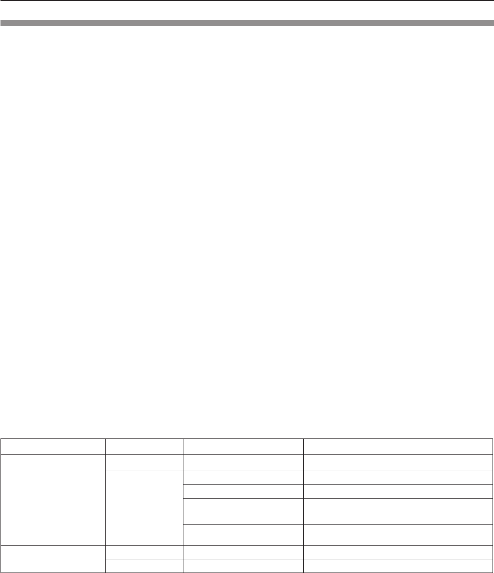
rAvailable wireless LAN channels
The channels (frequency range) that can be used differ according to the country or region. Refer to the table below.
Country or region Standard Channels used Frequency band (Center frequency)
North America
IEEE802.11b/g/n 1 - 11 channel 2.412 GHz - 2.462 GHz
IEEE802.11a/n
36 / 40 / 44 / 48 channel 5.180 GHz - 5.240 GHz
52 / 56 / 60 / 64 channel 5.260 GHz - 5.320 GHz
100 / 104 / 108 / 112 / 116 /
132 / 136 / 140 channel
5.500 GHz - 5.700 GHz
(except 5.600 GHz - 5.650 GHz)
149 / 153 / 157 / 161 / 165
channel 5.745 GHz - 5.825 GHz
Other counties IEEE802.11b/g/n Passive scanning 2.412 GHz - 2.472 GHz
IEEE802.11a/n Passive scanning 5.745 GHz - 5.805 GHz
The frequency and channel differ depending on the country.
The passive scanning is performed by changing radio to the channel being scanned in each country.
Please use the wireless LAN feature in compliance with the laws of each country.
zFor North America
This device is restricted to indoor use when operated in the 5.15 to 5.25 GHz frequency range (Channels 36 to 48).
ENGLISH - 21
Chapter 1 Preparation - Precautions for use

About Wireless LANs
The advantage of a wireless LAN is that information can be exchanged between a PC or other such equipment and an
access point using radio waves as long as you are within range for radio transmissions.
On the other hand, because the radio waves can travel through obstacles (such as walls) and are available everywhere
within a given range, problems of the type listed below may occur if security-related settings are not made.
fA malicious third-part may intentionally intercept and monitor transmitted data including the content of e-mail and
personal information such as your ID, password, and/or credit card numbers.
fA malicious third-party may access your personal or corporate network without authorization and engage in the
following types of behavior.
Retrieve personal and/or secret information (information leak)
Spread false information by impersonating a particular person (spoong)
Overwrite intercepted communications and issue false data (tampering)
Spread harmful software such as a computer virus and crash your data and/or system (system crash)
Since most wireless LAN adapters or access points are equipped with security features to take care of these problems,
you can reduce the possibility of these problems occurring when using this product by making the appropriate security
settings for the wireless LAN device.
Some wireless LAN devices may not be set for security immediately after purchase. To decrease the possibility of
occurrence of security problems, before using any wireless LAN devices, be absolutely sure to make all security-related
settings according to the instructions given in the operation manuals supplied with them.
Depending on the specications of the wireless LAN, a malicious third-party may be able to break security settings by
special means.
Panasonic asks customers to thoroughly understand the risk of using this product without making security settings, and
recommends that the customer make security settings at their own discretion and responsibility.
22 - ENGLISH
Chapter 1 Preparation - Precautions for use
Accessories
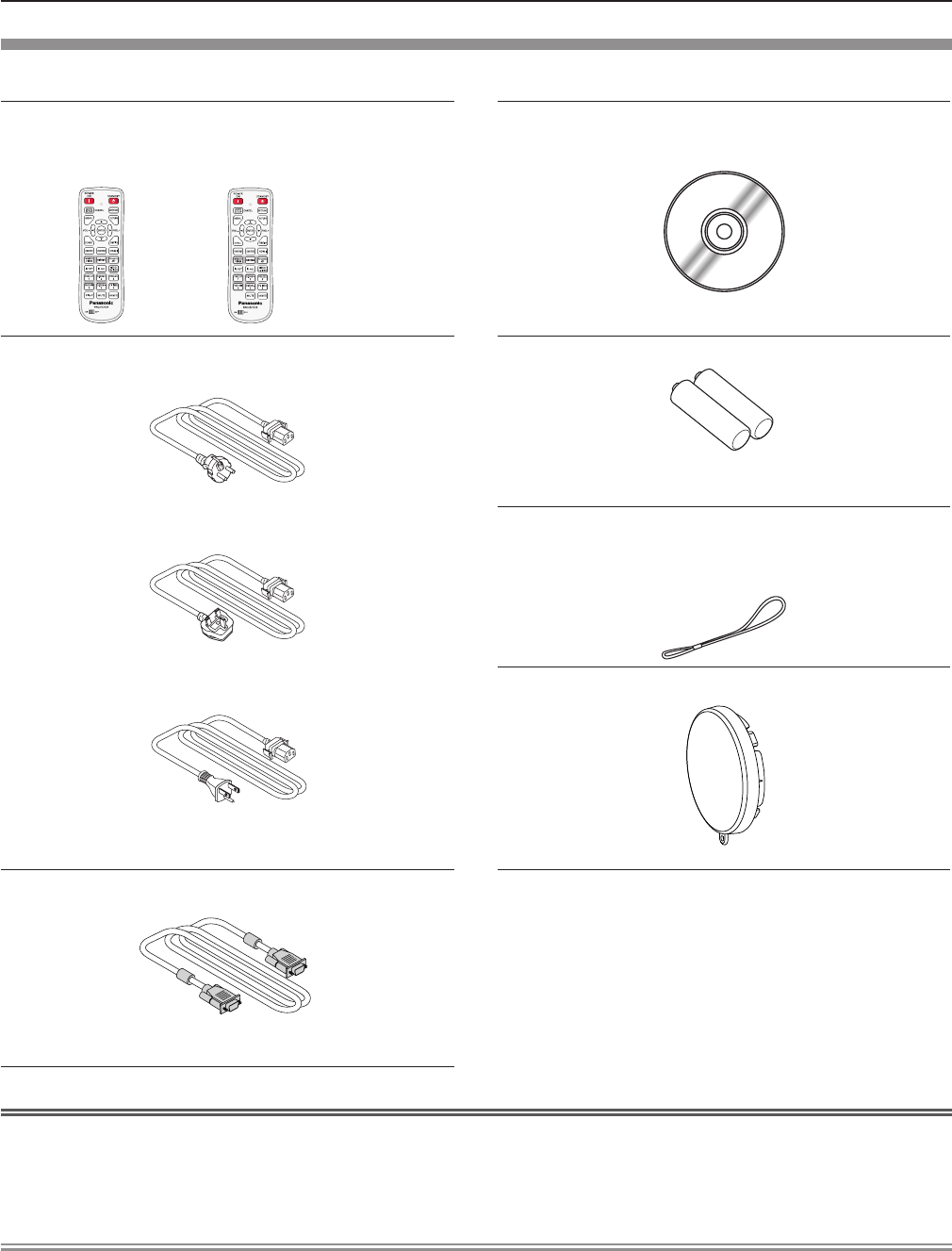
Make sure the following accessories are provided with your projector. Numbers enclosed < > show the number of accessories.
Wireless remote control unit <1>
(N2QAYA000101) (N2QAYA000100)
PT-VW355N PT-VX425N
CD-ROM <1>
(TXFQB02VMC2)
Power cord
(TXFSX02UXRZ)
AAA/R03 or AAA/LR03 battery <2>
(for remote control unit)
(TXFSX02UYAZ) String <1>
(for lens cap)
(6103504711)
(TXFSX02UFEZ) Lens cap <1>
(TKKL5568)
RGB signal cable <1>
(K1HY15YY0012)
Attention
fAfter unpacking the projector, discard the power cord cap and packaging material properly.
fDo not use the supplied power cord for devices other than this projector.
fFor lost accessories, consult your dealer.
fStore small parts in an appropriate manner, and keep them away from young children.
Note
fThe type and number of the power cord depend on the country in which you purchased the product.
fThe model numbers of accessories are subject to change without prior notice.
fThe supplied string is used for lens cap, refer to “Attaching the Lens Cap” (x page 30).
ENGLISH - 23
Chapter 1 Preparation - Precautions for use
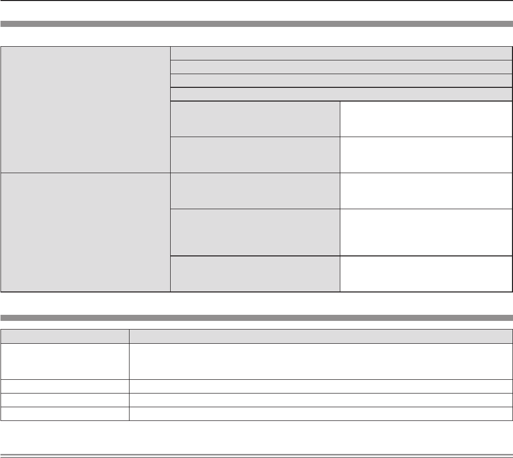
Contents of the supplied CD-ROM
The contents of the supplied CD-ROM are as follow.
Instruction/list (PDF)
Operating Instructions – Functional Manual
Operating Instructions – Multi Projector Monitoring & Control Software
Operating Instructions – Logo Transfer Software
Operating Instructions – Wireless Manager ME6.3
List of Compatible Projector Models
This is a list of projectors that are com-
patible with the software contained in the
CD-ROM and their restrictions.
Software license
The open source software licenses that
used in this projector are included in the
PDF les.
Software
Multi Projector Monitoring & Control
Software (Windows)
This software allows you to monitor and
control multiple projectors connected to
the LAN.
Logo Transfer Software (Windows)
This software allows you to transfer
original images, such as company logos
to be displayed when projection starts, to
the projector.
Wireless Manager ME6.3
(Windows/Mac)
This software allows you to send com-
puter screen displays over wireless/wired
LAN.
Optional accessories
Options Model No.
Ceiling Mount Bracket
ET-PKL100H (for high ceilings)
ET-PKL100S (for low ceilings)
ET-PKV400B (Projector Mount Bracket)
Replacement Lamp Unit ET-LAV300
Replacement Filter Unit ET-RFV300
Easy Wireless Stick*1ET-UW100
*1 This product can be purchased in the U.S., Canada, Japan and the European Communities.
Note
fThe model numbers of optional accessories are subject to change without prior notice.
24 - ENGLISH
Chapter 1 Preparation - Precautions for use
About your projector
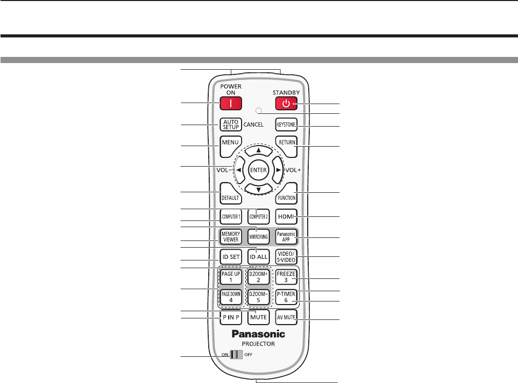
Remote control
This jack is not used for these
projector models.
1
2
3
5
6
7
8
9
4
10
11
12
13
14
15
16
17
18
19
20
21
22
23
24
25
27
28
26
29
1 Remote control signal emitters
2 Power on <b> button
Turn the projector on.
3 <AUTO SETUP/CANCEL> button
Automatically adjusts the image display position while
projecting the image. In addition, it acts as <CANCEL>
button when using the MEMORY VIEWER function.
(x page 49)
4 <MENU> button
Open or close the On-Screen Menu. (x page 56)
5 <ENTER> button/asq(VOL -) w(VOL+) buttons
Navigate the menu display.
Adjust the volume.
6 <DEFAULT> button
Resets the content of the sub-menu to the factory
default. (x page 57)
Or deletes one character when you enter an IP address
or a text.
7 <COMPUTER 2> button
Switches the COMPUTER2 signal to project.
8 <COMPUTER 1> button
Switches the COMPUTER1 signal to project.
9 <MIRRORING> button
Switches the MIRRORING signal to project.
(x page 51)
10 <MEMORY VIEWER> button
Switches the MEMORY VIEWER signal to project.
(x page 50)
11 <ID ALL> button
Used to simultaneously control all the projectors with one
remote control for a system using multiple projectors.
(x page 29)
12 <ID SET> button
Sets the ID number of the remote control to use for a
system using multiple projectors. (x page 29)
13 <D.ZOOM +/-> buttons
Zoom in and out the images. (x page 52)
14 <PAGE UP/PAGE DOWN> buttons
You can page up or page down les such as PowerPoint
through "Wireless Manager ME6.3". (x page 51)
15 <MUTE> button
Used to mute the audio. (x page 54)
16 <P IN P> button (Only for PT-VW355N)
Operate the P IN P function. (x page 53)
17 <ON/OFF> switch
When using the remote control, set this switch to “ON”.
Set it to “OFF” to avoid misoperation when it is not in use.
18 Power standby <v> button
Turn the projector off.
19 Remote control indicator
Flashes if any button in the remote control is pressed.
20 <KEYSTONE> button
Correct keystone distortion. (x page 49)
21 <RETURN> button
Return to the previous menu or cancel the setting.
22 <FUNCTION> button
Assigns a frequently used operation as a shortcut button.
23 <HDMI> button
Switches the HDMI signal to project.
24 <Panasonic APP> button
Switches the Panasonic APPLICATION signal to project.
25 <VIDEO/S-VIDEO> button
Switches the VIDEO signal or S-VIDEO signal to project.
26 <FREEZE> button
Pauses the projected image and mute the audio
temporarily. (x page 53)
27 Number buttons
Act as number buttons. Use these buttons when setting
the remote control codes or entering the password.
28 <P-TIMER> button
Operate the P-TIMER function. (x page 54)
29 <AV MUTE> button
Used to turn off the audio and video temporarily.
(x page 53)
ENGLISH - 25
Chapter 1 Preparation - About your projector
Attention
fDo not drop the remote control.
fAvoid contact with liquids.
fDo not attempt to modify or disassemble the remote control.
fPlease observe the following contents that are described on
the back of the remote control unit (see the right picture).
1. Do not use a new battery together with an old battery.
2. Do not use unspecied batteries.
3. Make sure the polarities (+ and -) are correct when inserting the batteries.
fIn addition, please read the contents that are related to batteries in the "Read this rst!".
Note
fThe remote control can be used within a distance of about 7 m (22'11-5/8") if pointed directly at the remote control signal
receiver. The remote control can control at angles of up to ± 30 ° vertically and ± 30 ° horizontally, but the effective control
range may be reduced.
fIf there are any obstacles between the remote control and the remote control signal receiver, the remote control may not
operate correctly.
fYou can operate the projector by reecting the remote control signal on the screen. The operating range may differ due to
the loss of light caused by the properties of the screen.
fWhen the remote control signal receiver is lit with a uorescent light or other strong light source, the projector may become
inoperative. Set the projector as far from the luminous source as possible.
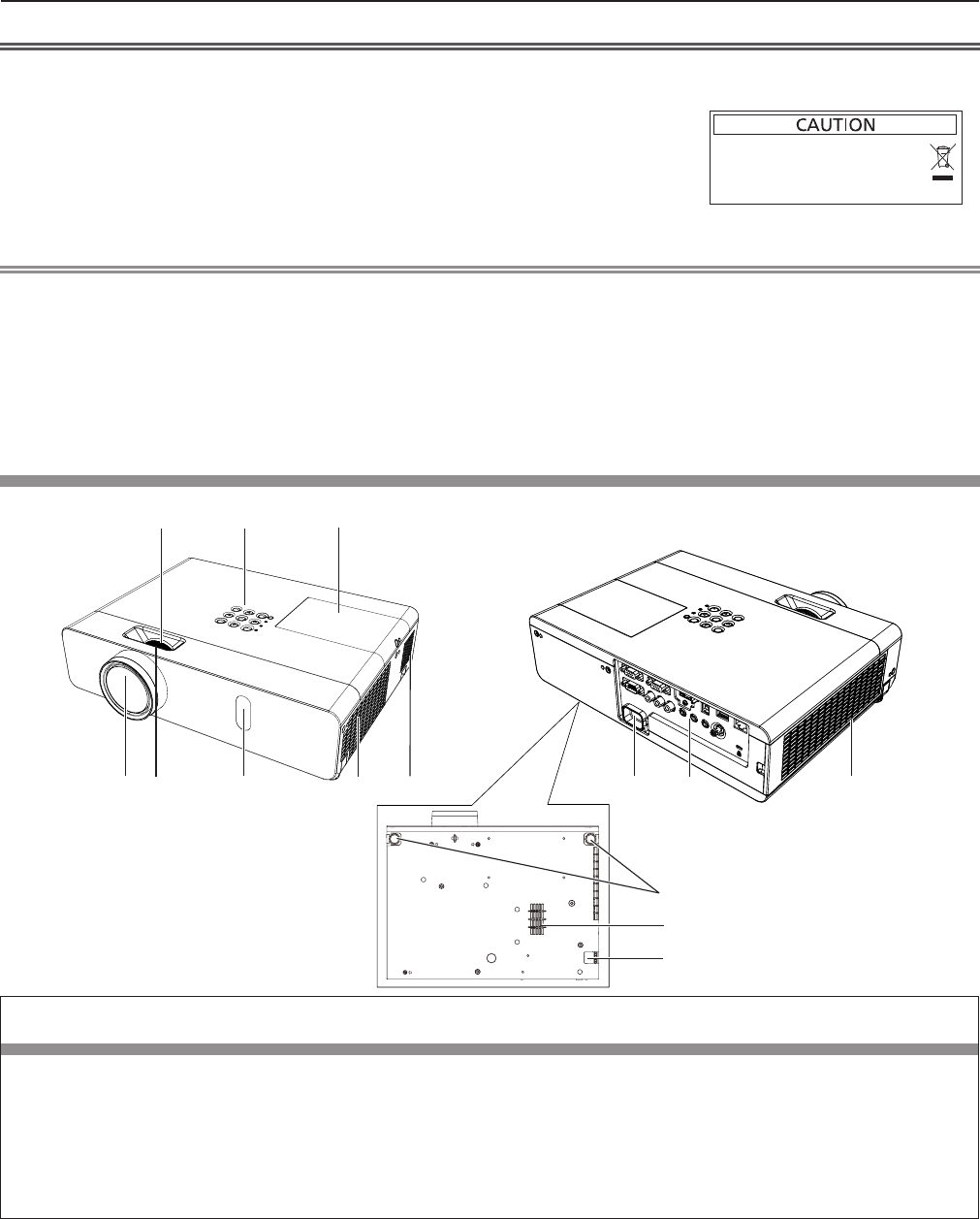
Projector body
1 2 3
4678 9 10 11
12
5
14
13
WARNING
Keep your hands and other objects away from the air exhaust port and the air intake port (bottom).
fKeep your hand and face away.
fDo not insert your nger.
fKeep heat-sensitive articles away.
Heated air from the air exhaust port can cause burns or external damage.
When using the projector on a ceiling and powering off with the Direct Power Off function, the heated air from the air intake
port in the bottom can cause burns or external damage.
1 Zoom ring (Back)
Adjust the zoom.
2 Control Panel and Indicators (x page 27)
3 Lamp cover (x page 128)
The lamp unit is located inside.
4 Projection Lens
5 Focus ring (Front)
Adjust the focus.
6 Remote control signal receiver/Camera
7 Air exhaust port
8 Speaker
9 <AC IN> terminal
Connect the supplied power cord.
10 Connecting terminals (x page 28)
11 Air intake port (Side) / Air lter cover (x page 126)
The air lter unit is inside.
12 Adjustable feet
Adjust the projection angle.
1. 请勿把旧电池和新电池一起使用。
2. 请勿使用不合规格的电池。
3. 确保电池安装正确。
原产地:中国
1.Do not use old battery with new one.
2.Do not use batteries other than the
type specified.
3.Be sure the batteries are inserted properly.
Made in China
26 - ENGLISH
Chapter 1 Preparation - About your projector
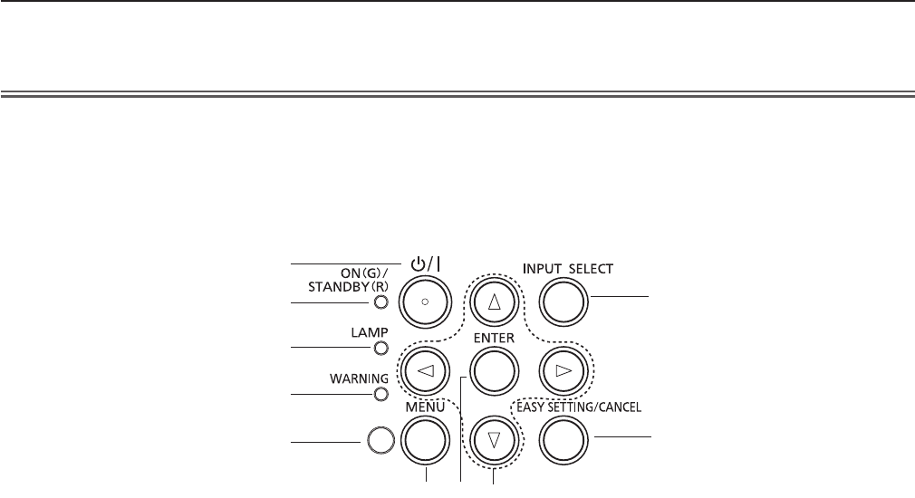
rControl panel and Indicators
1
2
3
4
5
678
9
10
1 Power <v/b> button
Turns the projector on/off.
(v standby / b power on)
2 Power indicator <ON(G)/STANDBY(R)>
Displays the status of the power.
3 Lamp indicator <LAMP>
Displays the status of the lamp.
4 Warning indicator <WARNING>
Indicates the abnormal conditions of the projector.
5 Ambient Luminance sensor
Detects room’s light and select proper image quality.
6 <MENU> button
Displays the menu screen. (x page 56)
7 <ENTER> button
Determines and executes an item in the menu screen.
8 asqw buttons
Navigates the menu screen.
Adjusts the volume level (qw).
9 <INPUT SELECT> button
Selects the input signal for projection. (x page 50)
10 <EASY SETTING/CANCEL> button
Executes the EASY SETTING function.
In addition, it acts as <CANCEL> button when using the
MEMORY VIEWER function.
13 Air intake port (Bottom) 14 Security Chain Hook
Attaches a burglar prevention cable, etc.
Attention
fDo not block the ventilation ports (intake and exhaust) of the projector.
ENGLISH - 27
Chapter 1 Preparation - About your projector
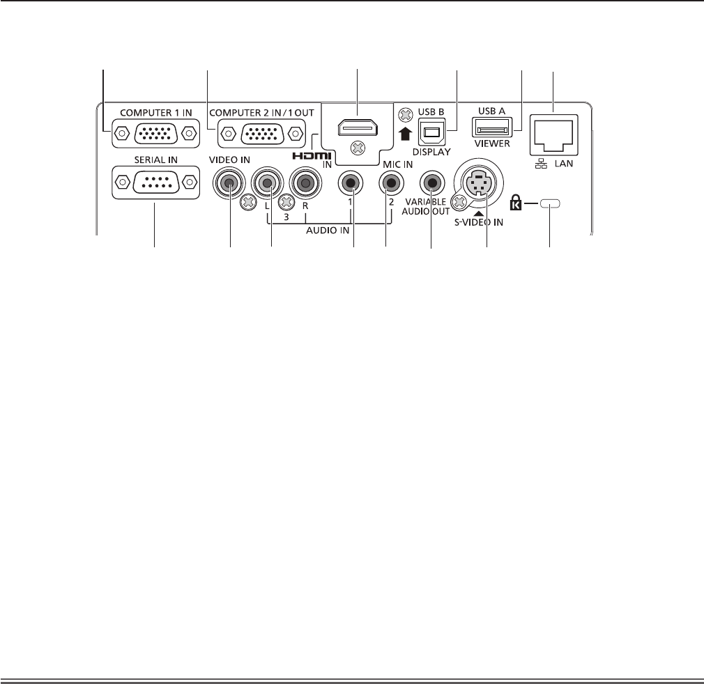
rConnecting terminals
1234 5 6
78 9 10 11 12 13 14
1 <COMPUTER 1 IN> terminal
This is the terminal to input RGB or YCBCR/YPBPR
signals.
2 <COMPUTER 2 IN/ 1 OUT> terminal
This is the terminal to input RGB signals.
Or output the RGB or YCBCR/YPBPR signals to external
monitor.
3 <HDMI IN> terminal
This is the terminal to input HDMI signals.
4 <USB B (DISPLAY)> terminal
This terminal is used to connect the projector to the
computer with a USB cable when you want to use
the USB display function of the application software
“Wireless Manager ME6.3”.
For details, please refer to the “Operating Instructions-
Wireless Manager ME6.3” in CD-ROM.
5 <USB A (VIEWER)> terminal
This terminal is to insert the USB memory directly.
6 <LAN> terminal
This is the LAN terminal to connect to the network.
7 <SERIAL IN> terminal
This is the RS-232C compatible terminal to externally
control the projector by connecting a computer.
8 <VIDEO IN> terminal
This is the terminal to input video signals.
9 <AUDIO IN 3 (L/R)> terminal
This is the terminal to input audio signals.
Left input (L) and right input (R) are provided for the
<AUDIO IN 3> terminal.
10 <AUDIO IN 1> terminal
This is the terminal to input audio signals.
11 <AUDIO IN 2 (MIC IN)> terminal
This is the terminal to input audio signals. Or connect
the
MIC to this terminal.
12 <VARIABLE AUDIO OUT> terminal
This is the terminal to output the input audio signal to the
projector.
13 <S-VIDEO IN> terminal
This is the terminal to input s-video signals.
14 Security slot
Attach the commercial shackle lock, manufactured by
Kensington, to protect your projector. Compatible with
the Kensington MicroSaver Security System.
Attention
fWhen a LAN cable is directly connected to the projector, the network connection must be made indoors.
28 - ENGLISH
Chapter 1 Preparation - About your projector
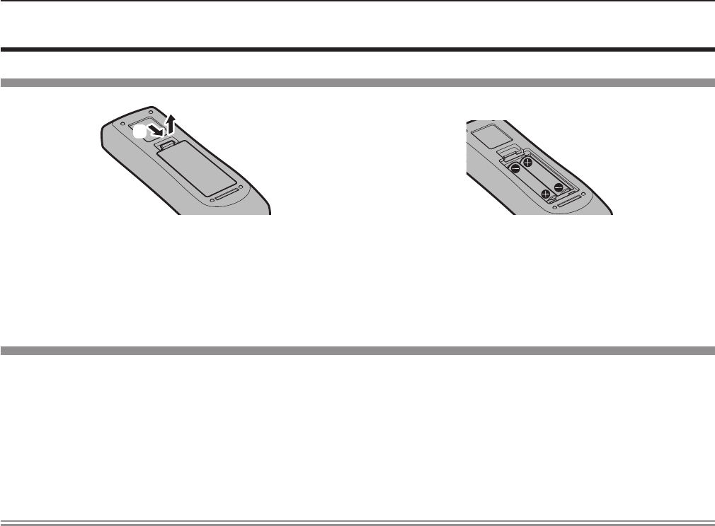
Preparing the remote control
Inserting and removing batteries
(ii)
(i)
Fig. 1 Fig. 2
1) Open the cover. (Fig. 1)
2) Insert batteries and close the cover. (Insert the "m" side first.) (Fig. 2)
fWhen removing the batteries, perform the steps in reverse order.
When using the system with multiple projectors
When you use the system with multiple projectors, you can operate all the projectors simultaneously or each projector
individually by using single remote control, if a unique ID number is assigned to each projector.
When you want to set the ID number, at rst you need to complete the Initial setting, and then after setting the ID number of
the projector, set the ID number on the remote control. About Initial setting, please refer to “When the initial setting screen is
displayed” (x page 42).
The factory default ID number of the unit (the projector and the remote control) is set to [ALL], you can control with this setting.
If necessary, please set the ID number to the remote control and the projector. About how to set the ID number of the remote
control, please refer to “Setting the ID number of the remote control” (x page 54).
Note
fSet the ID number of the projector from the [PROJECTOR SETUP] menu → [PROJECTOR ID]. (x page 78)
ENGLISH - 29
Chapter 1 Preparation - Preparing the remote control
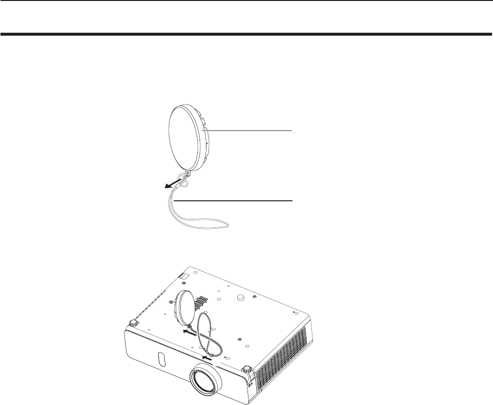
Attaching the Lens Cap
When moving this projector or while not using it over an extended period of time, attach the lens cap.
To prevent loss for the lens cap, please according to the following procedures, attach the lens cap with the string of
accessories.
1) Thread the thinner end of the string through the hole on the lens cap.
Lens cap
String
2) Thread the other end of the string through the hole on the bottom of the projector.
(ii)
(i)
30 - ENGLISH
Chapter 1 Preparation - Attaching the Lens Cap

Chapter 2 Getting Started
This chapter describes things you need to do before using the projector such as the setup and
connections.
ENGLISH - 31
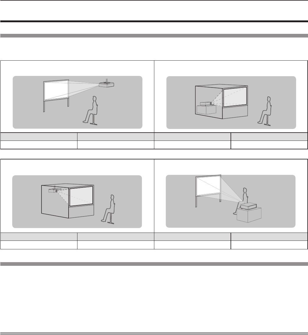
Setting up
Installation mode
There are four ways to set up the projector. Set the [PROJECTOR SETUP] menu → [PROJECTION METHOD] (x page 78)
depending on the installation location.
Mounting on the ceiling and projecting forward Setting on a desk/oor and projecting from rear
(Using the translucent screen)
Menu item Method Menu item Method
[PROJECTION METHOD] [FRONT/CEILING] [PROJECTION METHOD] [REAR/DESK]
Mounting on the ceiling and projecting from rear
(Using the translucent screen)
Setting on a desk/oor and projecting forward
Menu item Method Menu item Method
[PROJECTION METHOD] [REAR/CEILING] [PROJECTION METHOD] [FRONT/DESK]
Parts for ceiling mount (optional)
This requires an optional ceiling mount bracket. Be sure to use the Projector Mount Bracket together with the ceiling mount
bracket for high ceilings or low ceilings.
Model No.:
① ET-PKL100H (for high ceilings), ET-PKV400B (Projector Mount Bracket)
② ET-PKL100S (for low ceilings), ET-PKV400B (Projector Mount Bracket)
fUse only the ceiling mount brackets specied for this projector.
fRefer to the Installation Instructions for the ceiling mount bracket when you install the bracket and the projector.
Attention
fTo ensure projector performance and security, installation of the ceiling mount bracket must be carried by your dealer or a
qualied technician.
32 - ENGLISH
Chapter 2 Getting Started - Setting up
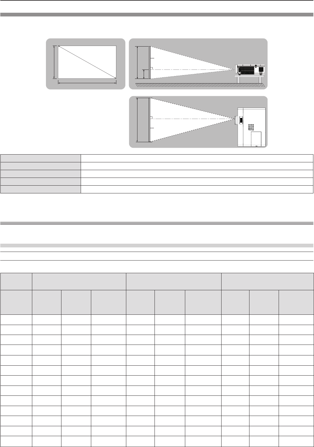
Screen size and throw distance
Refer to the screen size and projection distances to install the projector. Image size and image position can be adjusted in
accordance with the screen size and screen position.
Projected image
SH
SW
SD
SH
Screen
L (LW/LT)
Screen
L (LW/LT)
SW
H
L (LW/LT) *1Projection distance (m)
SH Image height (m)
SW Image width (m)
HDistance from the center of lens to the image lower end (m)
SD Projected image size (m)
*1 LW : Minimum distance
LT : Maximum distance
Attention
fBefore installing, please read “Precautions for Use” (x page 18).
Projection distance
For PT-VW355N
All measurements below are approximate and may differ slightly from the actual measurements. (Unit: m)
Projection
size For 4:3 aspect ratio For 16:9 aspect ratio For 16:10 aspect ratio
Screen
diagonal
(SD)
Minimum
distance
(LW)
Maximum
distance
(LT)
Height
position
(H)
Minimum
distance
(LW)
Maximum
distance
(LT)
Height
position (H)
Minimum
distance
(LW)
Maximum
distance
(LT)
Height
position (H)
0.76 (30") 0.83 1.37 0.009 0.76 1.24 -0.012 0.73 1.21 0.008
1.02 (40") 1.13 1.85 0.012 1.02 1.68 -0.017 0.99 1.63 0.011
1.27 (50") 1.41 2.31 0.015 1.28 2.09 -0.021 1.25 2.04 0.013
1.52 (60") 1.70 2.77 0.018 1.54 2.51 -0.025 1.50 2.44 0.016
1.78 (70") 1.99 3.25 0.021 1.81 2.95 -0.029 1.76 2.87 0.019
2.03 (80") 2.28 3.71 0.024 2.07 3.37 -0.033 2.01 3.27 0.022
2.29 (90") 2.57 4.19 0.027 2.33 3.80 -0.037 2.27 3.70 0.024
2.54 (100") 2.86 4.65 0.030 2.59 4.22 -0.041 2.52 4.10 0.027
3.05 (120") 3.44 5.59 0.037 3.12 5.07 -0.050 3.03 4.93 0.032
3.81 (150") 4.30 6.99 0.046 3.90 6.34 -0.062 3.80 6.17 0.040
5.08 (200") 5.74 9.33 0.061 5.21 8.47 -0.083 5.07 8.24 0.054
6.35 (250") 7.19 11.67 0.076 6.52 10.59 -0.104 6.34 10.30 0.067
7.62 (300") 8.63 14.01 0.091 7.82 12.72 -0.124 7.62 12.37 0.081
ENGLISH - 33
Chapter 2 Getting Started - Setting up
For PT-VX425N
All measurements below are approximate and may differ slightly from the actual measurements. (Unit: m)
Projection size For 4:3 aspect ratio For 16:9 aspect ratio
Screen diagonal (SD)
Minimum
distance
(LW)
Maximum
distance
(LT)
Height position (H)
Minimum
distance
(LW)
Maximum
distance
(LT)
Height position (H)
0.76 (30") 0.69 1.14 0.046 0.75 1.24 -0.012
1.02 (40") 0.94 1.54 0.061 1.02 1.68 -0.017
1.27 (50") 1.17 1.92 0.076 1.28 2.09 -0.021
1.52 (60") 1.41 2.30 0.091 1.54 2.51 -0.025
1.78 (70") 1.65 2.70 0.107 1.81 2.94 -0.029
2.03 (80") 1.89 3.08 0.122 2.06 3.36 -0.033
2.29 (90") 2.14 3.48 0.137 2.33 3.80 -0.037
2.54 (100") 2.37 3.87 0.152 2.59 4.21 -0.031
3.05 (120") 2.86 4.65 0.183 3.11 5.07 -0.050
3.81 (150") 3.58 5.81 0.229 3.90 6.33 -0.062
5.08 (200") 4.78 7.76 0.305 5.21 8.45 -0.083
6.35 (250") 5.98 9.70 0.381 6.52 10.57 -0.104
7.62 (300") 7.18 11.65 0.457 7.82 12.70 -0.124
Projection distance formulas
Any other projection distance can be obtained according to the screen dimensions (m) by using the following calculations.
The calculated distance may contain a certain error.
If you want to calculate the projection distance with projected image size SD (unit: inch) by substituting, please assign 0.0254
times to the SD value.
For PT-VW355N
For 4:3 aspect ratio For 16:9 aspect ratio For 16:10 aspect ratio
Screen height (SH) = 0.6 × SD(m) = 0.490 × SD(m) = 0.530 × SD(m)
Screen width (SW) = 0.8 × SD(m) = 0.872 × SD(m) = 0.848 × SD(m)
Minimum distance (LW) = 1.1363 × SD(m) - 0.0290 = 1.0316 × SD(m) - 0.0290 = 1.0037 × SD(m) - 0.0290
Maximum distance (LT) = 1.8422 × SD(m) - 0.0292 = 1.6725 × SD(m) - 0.0292 = 1.6273 × SD(m) - 0.0292
For PT-VX425N
For 4:3 aspect ratio For 16:9 aspect ratio
Screen height (SH) = 0.6 × SD(m) = 0.490 × SD(m)
Screen width (SW) = 0.8 × SD(m) = 0.872 × SD(m)
Minimum distance (LW) = 0.9461 × SD(m) - 0.0295 = 1.0307 × SD(m) - 0.0295
Maximum distance (LT) = 1.5324 × SD(m) - 0.0272 = 1.6696 × SD(m) - 0.0272
34 - ENGLISH
Chapter 2 Getting Started - Setting up
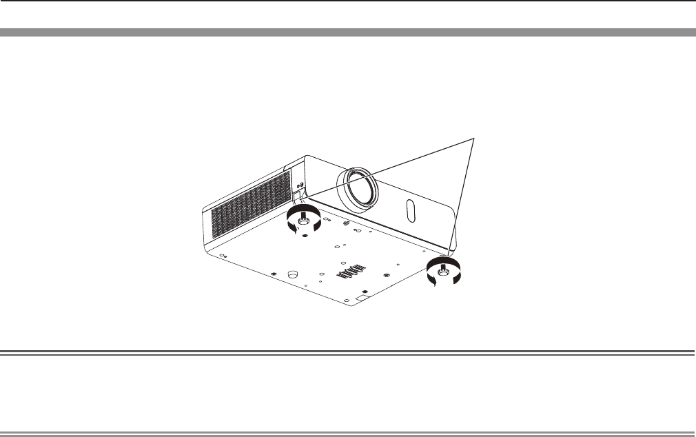
Adjusting adjustable feet
Lift the front of the projector and press the feet lock latches on both side of the projector.
Release the feet lock latches to lock the adjustable feet and rotate the adjustable feet to a proper height and tilt.
Extend the adjustable feet by rotating in the direction shown in the gure and retract by rotating in the opposite
direction.
Feet lock latches
Adjustable range
Adjustable feet : 43 mm (1-11/16")
Attention
fHeated air comes out of the air exhaust port while the lamp is lit. Do not touch the air exhaust port directly when you adjust
the adjustable feet.
fIf keystone distortion occurs on the projected image, perform [KEYSTONE] from the [POSITION] menu. (x page 65)
Note
fScrew up the adjustable feet, and an audible click will be heard as the limit.
ENGLISH - 35
Chapter 2 Getting Started - Setting up
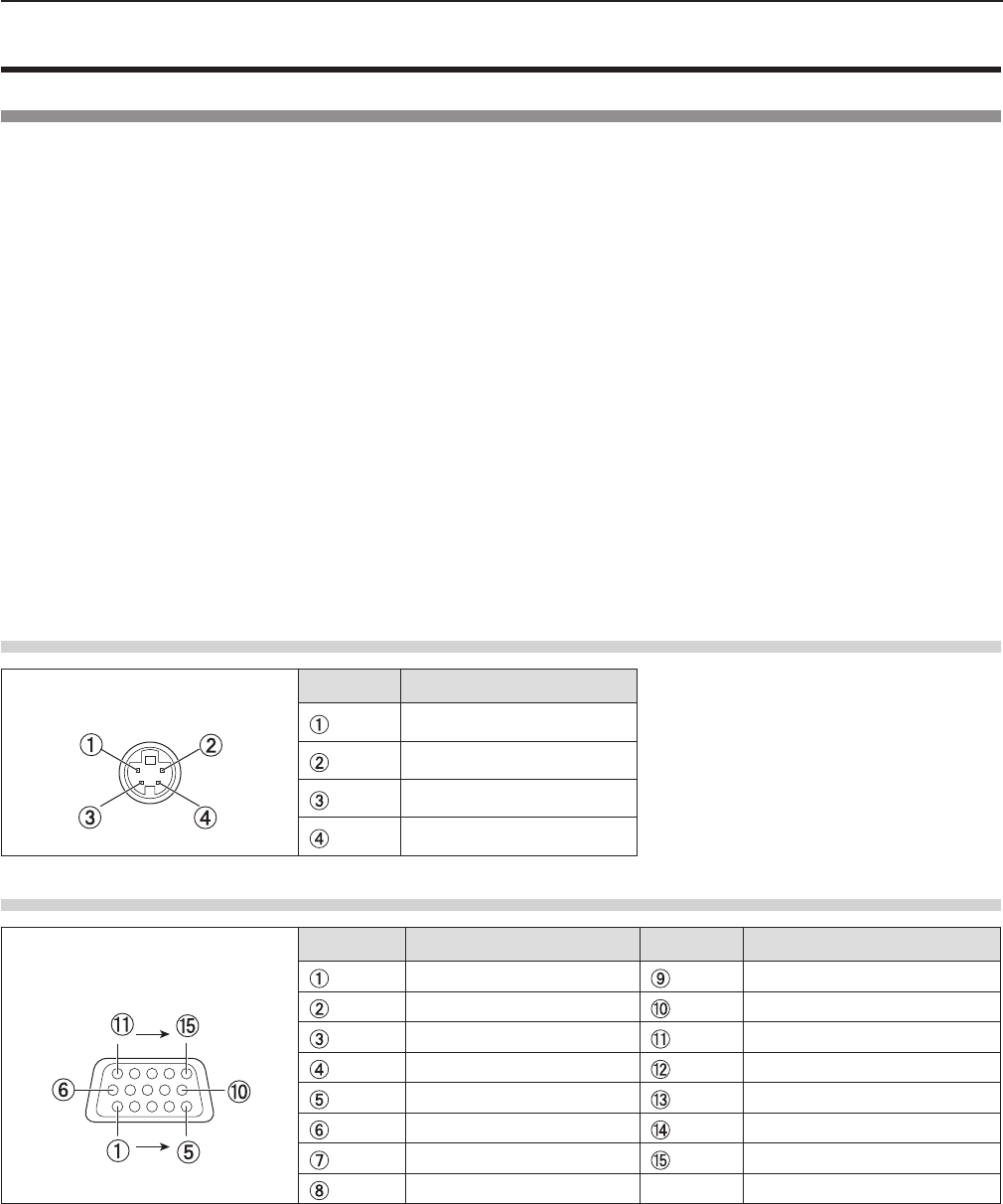
Connecting
Before connecting
fBefore connecting, carefully read the operating instructions for the external device to be connected.
fTurn off the power switch of the devices before connecting cables.
fTake note of the following points before connecting the cables. Failure to do so may result in malfunctions.
- When connecting a cable to a device connected to the projector or the projector itself, touch any nearby metallic objects to
eliminate static electricity from your body before performing work.
- Do not use unnecessarily long cables to connect to a device connected to the projector or to the projector body. The longer
the cable, the more it is susceptible to noise. Since using a cable while it is wound makes it act like an antenna, it is more
susceptible to noise.
- When connecting cables, connect GND rst, then insert the connecting terminal of the connecting device in a straight
manner.
fIf any connection cable is not supplied with the device, or if no optional cable is available for connection of the device,
prepare a necessary system connection cable to suit the device.
fVideo signals containing too much jitter may cause the images on the screen to randomly wobble or wafture. In this case, a
time base corrector (TBC) must be connected.
fThe projector accepts VIDEO signals, S-VIDEO signals, YCBCR/YPBPR signals and analog RGB signals (synchronous
signals are TTL level), and digital signal.
fSome computer models or graphics cards are not compatible with the projector.
fWhen using long cables to connect with each of equipment to the projector, there is a possibility that the image will not be
output correctly unless a compensator is used.
fFor details on what video signals the projector supports, see “List of compatible signals”. (x page 141)
<S-VIDEO IN> terminal pin assignments and signal names
Outside view Pin No. Signal names
GND (luminance signal)
GND (color signal)
Luminance signal
Color signal
<COMPUTER 1 IN> terminal pin assignments and signal names
Outside view Pin No. Signal names Pin No. Signal names
R/PR+ 5 V
G/Y GND
B/PBGND
—DDC data
GND HD/SYNC
GND VD
GND DDC clock
GND
36 - ENGLISH
Chapter 2 Getting Started - Connecting
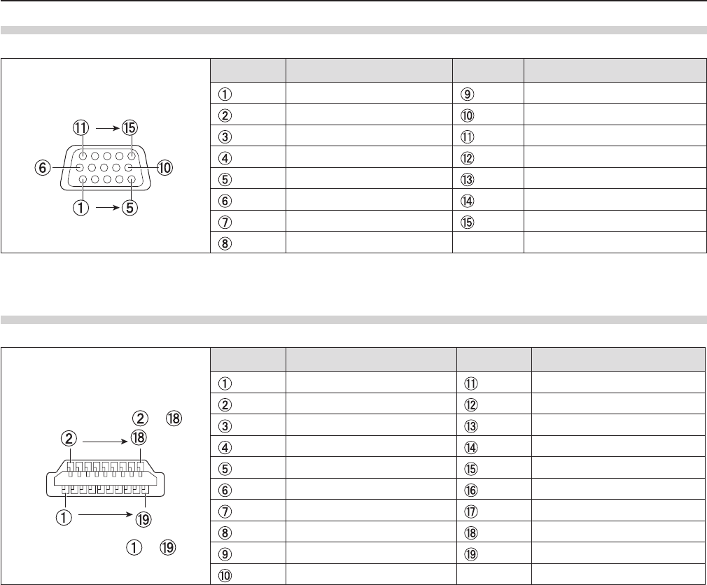
<COMPUTER 2 IN/1 OUT> terminal pin assignments and signal names
Outside view Pin No. Signal names Pin No. Signal names
R/PR*1+5 V
G/Y*1GND
B/PB*1—
—DDC data
GND HD/SYNC
GND VD
GND DDC clock
GND
*1: It is only for RGB signals when the terminal is used as the input terminal.
<HDMI IN> terminal pin assignments and signal names
Outside view Pin No. Signal names Pin No. Signal names
T.M.D.S data 2+ T.M.D.S clock shield
T.M.D.S data 2 shield T.M.D.S clock
-
T.M.D.S data 2
-
CEC
T.M.D.S data 1+ —
T.M.D.S data 1 shield SCL
T.M.D.S data 1
-
SDA
T.M.D.S data 0+ DDC/CEC GND
T.M.D.S data 0 shield +5 V
T.M.D.S data 0
-
Hot plug detection
T.M.D.S clock +
Odd-numbered pins to
Even-numbered pins to
ENGLISH - 37
Chapter 2 Getting Started - Connecting
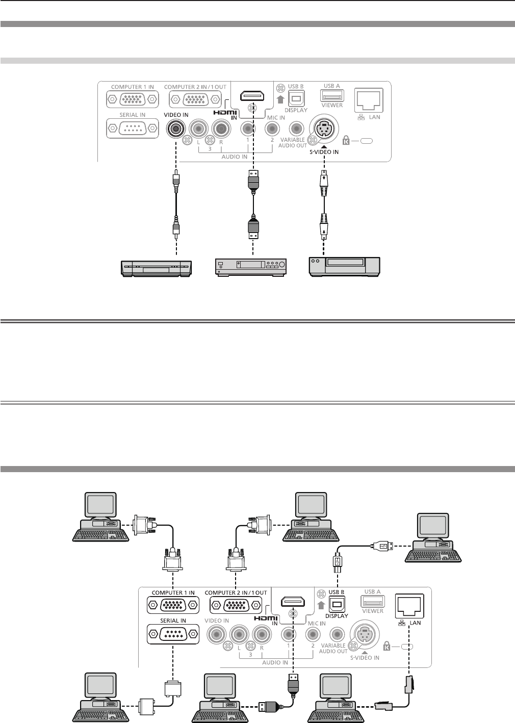
Connecting example : AV equipment
For <HDMI IN>/<VIDEO IN>/<S-VIDEO IN> terminals
DVD playerBlu-ray disk player
with HDMI terminal
Video deck (TBC built-in)
Attention
fAlways use one of the following when connecting a VCR.
- A VCR with built-in time base corrector (TBC).
- A time base corrector (TBC) between the projector and the VCR.
fIf nonstandard burst signals are connected, the image may be distorted. In such case, connect the time base corrector
(TBC) between the projector and the external devices.
Note
fFor an HDMI cable, use an HDMI High Speed cable that conforms to HDMI standards. If a cable that does not conform to
HDMI standards is used, images may be interrupted or may not be displayed.
fThis projector does not support the Viera link (HDMI).
Connecting example : Computers
Control computer Computer
Computer
Control computer
Computer
Computer
38 - ENGLISH
Chapter 2 Getting Started - Connecting
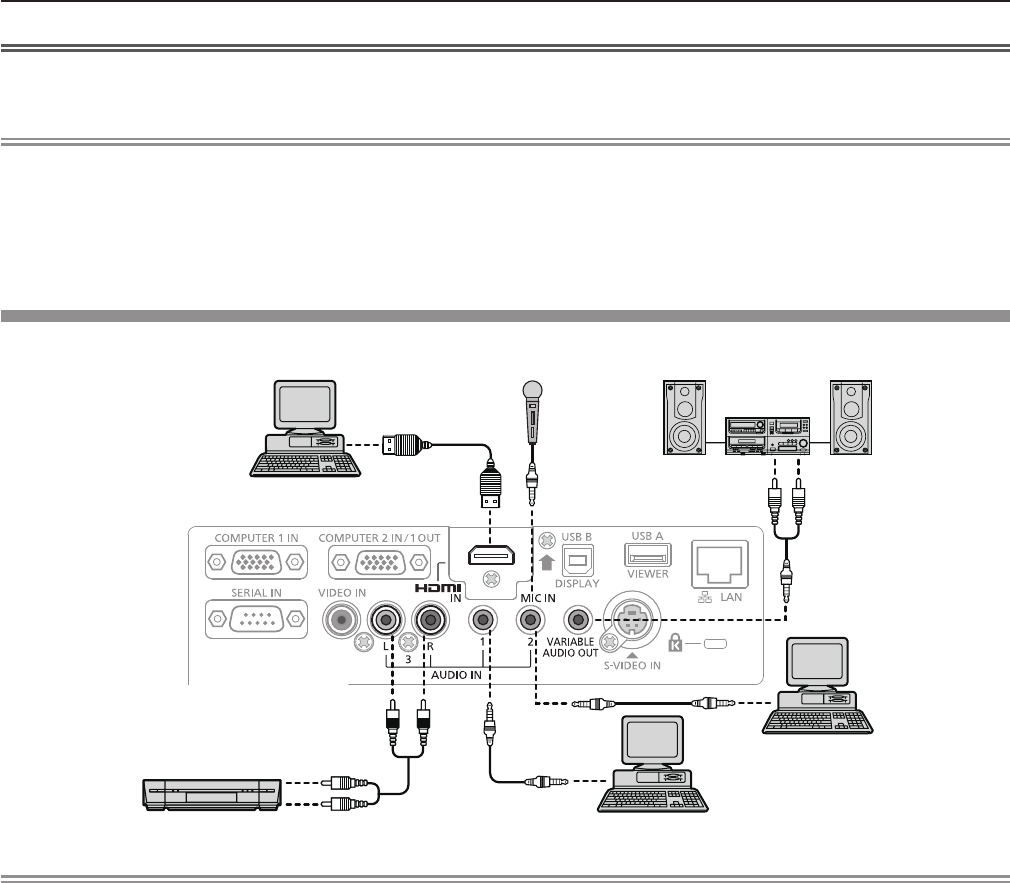
Attention
fWhen connecting the projector to a computer or an external device, use the power cord supplied with each device and
commercially available shielded cables.
Note
fIf you operate the projector using the computer with the resume feature (last memory), you may have to reset the resume
feature to operate the projector.
fYou can project the image and video via wired LAN, wireless LAN or the <USB B (DISPLAY)> terminal to the projector. For
detailed information, refer to “Connecting with Wired LAN” (x page 97), “Connecting with Wireless LAN” (x page 98) or
the operating Instructions of “Wireless Manager ME6.3” in the supplied CD-ROM.
Connecting example : Audio
Computer MIC Audio equipment
AV equipment Computer
Computer
Note
fIf the [AUDIO IN SELECT] settings are incorrect, the projector may have malfunctions such as the absence of audio.
(x page 82)
fWhen the <VARIABLE AUDIO OUT> terminal is connected with cable, the sound will not be output from the built-in speaker.
ENGLISH - 39
Chapter 2 Getting Started - Connecting

Chapter 3 Basic Operations
This chapter describes basic operations to start with.
40 - ENGLISH