Paradox Security Systems NV75MR Indoor Wireless PIR detector with Anti Mask and Pet Immunity User Manual NV75MR EI00
Paradox Security Systems Indoor Wireless PIR detector with Anti Mask and Pet Immunity NV75MR EI00
Users Manual

NV75MR-EI00/c 12/2016
paradox.com
NV75MR
Installation Manual V1.0
Wireless
16 Meter Indoor Dual
Mironel Optics, Anti-Mask,
Pet Immunity Dual Detector
General Description
The NV75MR is an indoor industry-leading wireless detector
providing superior 16 meter detection with rock solid stability
thanks to the revolutionary dual Mironel Mirror/Fresnel PIR optics.
Combined with Paradox true Pet Immunity and best-in-the industry
active Anti-Mask technology (EN Grade 3). The NV75MR provides
an unmatched high security solution for any indoor installation.
Please Read
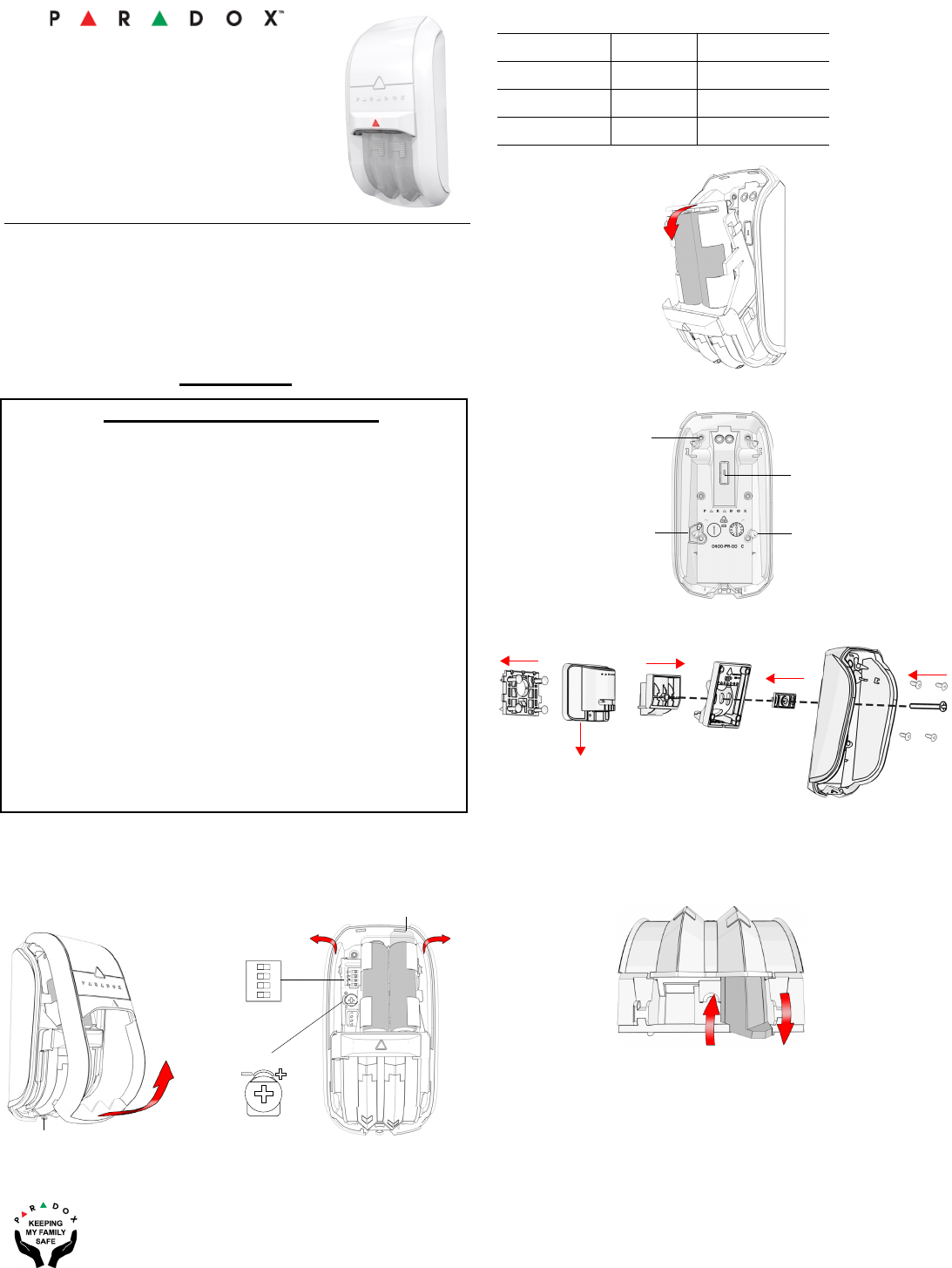
Installing the NV75MR (Step 1)
Installation Height:
Pet Immune ON - 2.0m/6.6ft to 2.4m/7.8ft
Pet Immune OFF - 2.0m/6.6ft to 2.8m/9ft (lever down)*
*For installations higher than 2.6m, when needed, tilt the detector
down a few degrees for best detection results; use of a bracket is
recommended.
Power Up (30 sec.):
Powering up the detector takes about 30 seconds, indicated with
green/red flashing; indicates PIR
stabilizing.
Anti-Mask Calibration:
Once detector is stabilized, as mentioned above, open
and close the tamper to initiate. Anti-Mask calibration
may take up to 60 seconds. Keep away from the
detector, at least 2 meters / 6 feet during calibration, indicated by
flashing green/red LED. Once completed,
the detector is ready.
Note: Do not block the detector’s field of view.
Table 1
Step 3
Wall Mount
Bracket Mount
Note: Use of a bracket reduces the detector’s security grade to 1.
Creep Zone/Pet Selection
Remove detector assembly as described in Step 1. When selector
is UP, Pet Mode; when DOWN, Creep Zone is active and there is
no Pet Immunity. Above 2.4m Pet Immune should be OFF (lever
down Pet OFF, see installation height note*.
12 3 4
ON
Cover Tamper
Step 1
DIP Switch
(Table 1)
PIR
SENSITIVITY
Battery Tab
11m
16m
13m
7m
9m
Step 2
OFF ON
1 - LED OFF ON
2 - EDGE DUAL SINGLE
3 - PET IMM. OFF ON
4 - MHz 868 MHz 433 MHz
Wall Mount x6
Bracket Adjustment
Screw Opening
Corner Mount
x4
Tamp e r S c rew
Wall/Corner
1
2
3
45
UP - Pet DOWN - Creep

NV75MR-EI00/c 12/2016
paradox.com
LED Display
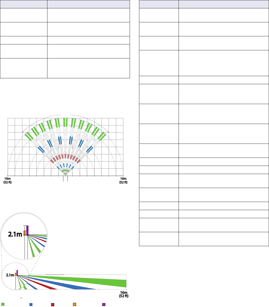
Beam Patterns
Top View
Side View
Technical Specifications
Feature LED Status Indicator
Tamper open Green: ON for 0.3 seconds every 30
seconds
PIR sensitivity level
setting
Green: Flashes 1-5 times according
to the selected level
Alarm detection Red: ON for 3 seconds
Booting/Tamper
close
Green/Red alternating flashes
for 45 seconds
Anti-mask detection Flashes orange rapidly (pre-alarm
state) and then flashes when in
alarm.
10m 16m
(52 ft)
90˚
2m2m 4m4m 6m6m 8m8m 12m 14m14m 10m12m
16m
(52 ft) 1.5m
Creep
Zone
1.5m
Creep
Zone
0m
60 cm
10m5.5m
3m
1.5m
Creep
Zone
16m
(52 ft)
60cm 12m
Detector 1 Detector 2
Both Detectors
2.1m
Optimal
2.8m
2.4m
Pet Immune ON Pet Immune OFF
3
m
1.5m
Creep
Z
one
p
60
c
m
D
etector
Bot
h
Detector
s
2.1m
Optimal
2.8m
2.4m
2.1m
2
.8m
2
.
4
m
2.1m
Optimal
2.8m
2.4m
* Read installation height note*
Specification Description
IR Movement
Detection
2 detectors, 2 dual element sensors, 2
Mironel Optics
Optics Two Mironel Mirror/W Fresnel optics
with mechanical Pet / Creep Zone
Coverage 16 meters/52 feet; 90° - complies with
EN50131-2-2 Grade 3
Anti-Masking Active IR with Dual detectors, blocking
items up to 30cm and lens applied
materials including clear lacquer; meets
and exceeds EN50131-2-2 Grade 3
Pet Immunity Pet up to 50cm will not be detected
Single/Dual
Edge
Infrared detection requires entry or exit
in single-mode; in Dual-edge, entry and
exit is required for both detectors
Creep Zone Mechanically selectable Creep Zone
detection 1.5m/4ft. (cancels Pet
Immunity when active)
Power Input 2 x 1.5 AA Alkaline batteries, up to 3
years for normal use with Active Anti-
Mask detection
Current
Consumption
Standby: 158uA, Max.: 18.3mA
Low Battery 2.2V
Frequency 433 or 868 MHz, internally selectable
Operating
Temperature
-35º to 50º C (-31º to 122º F)
Relative
humidity
95% non-condensing
Tamper Dual - Cover and Wall
Dimensions 128 x 62 x 54 mm/ 5.1 x 2.4 x2.1 in
Weight 120 gr/ 0.3 lb
160 gr / 0.4 lb (with batteries)
Certifications CE, EN50131-2-2 Grade 2, Class II,
EN 50131-6 Type C
Warranty
For complete warranty information on this product, please refer to the Limited Warranty Statement is found on the website:
www.paradox.com/terms or contact your local distributor. Specifications may change without prior notice.
Patents
US, Canadian and international patents may apply. Paradox is a trademark or registered trademark of Paradox Security Systems
NV75MR-EI00/c 12/2016
paradox.com
FCC and Industry Canada Compliance Statement
This device complies with FCC Rules Part 15 and with Industry
Canada license exempt RSS standard(s). Operation is subject to
two conditions:
1.This device may not cause harmful interference
2.This device must accept any interference that may be received
or that may cause undesired operation.
Le present appareil est conforme aux CNR d'Industrie Canada
applicables aux appareils radio exempts de licence. L'exploitation
est autorisee aux deux conditions
suivantes :
1.l'appareil ne doit pas produire de brouillage, et
2.l'utilisateur de l'appareil doit accepter tout brouillage
radioelectrique subi, meme si le brouillage est susceptible d'en
compromettre le fonctionnement.
FCC ID: KDYNV75MR
IC: 2438A-NV75MR
FCC WARNING
This equipment has been tested and found to comply with the
limits for a Class B digital device, pursuant to Part 15 of the FCC
Rules. These limits are designed to provide
reasonable protection against harmful interference in a residential
installation.
This equipment generates, uses and can radiate radio frequency
energy and, if not installed and used in accordance with the
instructions, may cause harmful interference
to radio communications.
However, there is no guarantee that interference will not occur in a
particular installation. If this equipment does cause harmful
interference to radio or television
reception, which can be determined by turning the equipment off
and on, the user is encouraged to try to correct the interference by
one or more of the following
measures:
• Reorient or relocate the receiving antenna.
• Increase the separation between the equipment and the
receiver.
• Connect the equipment into an outlet different from that to
which the receiver is connected.
• Consult the dealer or an experienced radio/TV technician for
help.
Changes or modifications to this equipment not expressly
approved by the party responsible for compliance (Paradox
Security Systems Ltd.) could void the user's
authority to operate the equipment.