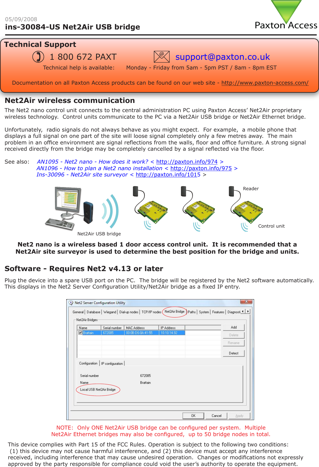
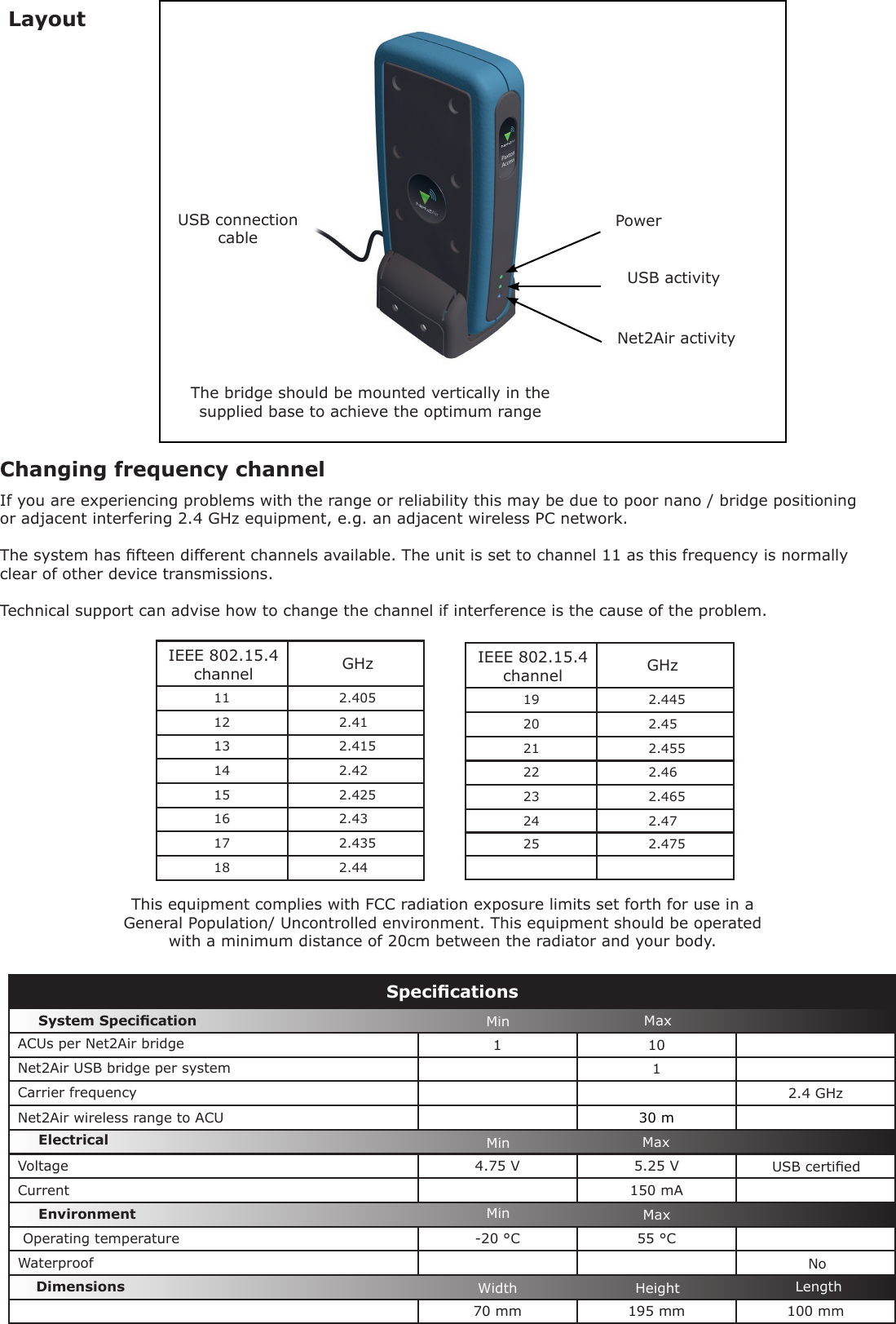
Paxton Access 477268 Net2Air USB Bridge User Manual INSTRUCTION Net2Air USB bridge

Paxton Access Ltd Net2Air USB Bridge INSTRUCTION Net2Air USB bridge

User Manual

Paxton Accessins-30084-US Net2Air USB bridge05/09/2008Technical SupportTechnical help is available:      Monday - Friday from 5am - 5pm PST / 8am - 8pm EST1 800 672 PAXT support@paxton.co.ukSoftware - Requires Net2 v4.13 or laterDocumentation on all Paxton Access products can be found on our web site - http://www.paxton-access.com/The Net2 nano control unit connects to the central administration PC using Paxton Access’ Net2Air proprietary wireless technology.  Control units communicate to the PC via a Net2Air USB bridge or Net2Air Ethernet bridge.Unfortunately,  radio signals do not always behave as you might expect.  For example,  a mobile phone that displays a full signal on one part of the site will loose signal completely only a few metres away.  The main problem in an ofce environment are signal reections from the walls, oor and ofce furniture. A strong signal received directly from the bridge may be completely cancelled by a signal reected via the oor.See also:  XAN1095 - Net2 nano - How does it work? < http://paxton.info/974 >X               AN1096 - How to plan a Net2 nano installation < http://paxton.info/975 >X               Ins-30096 - Net2Air site surveyor < http://paxton.info/1015 >Net2Air wireless communicationPlug the device into a spare USB port on the PC.  The bridge will be registered by the Net2 software automatically.  This displays in the Net2 Server Conguration Utility/Net2Air bridge as a xed IP entry.NOTE:  Only ONE Net2Air USB bridge can be congured per system.  Multiple Net2Air Ethernet bridges may also be congured,  up to 50 bridge nodes in total.ReaderControl unitNet2Air USB bridgeNet2 nano is a wireless based 1 door access control unit.  It is recommended that a Net2Air site surveyor is used to determine the best position for the bridge and units.This device complies with Part 15 of the FCC Rules. Operation is subject to the following two conditions: (1) this device may not cause harmful interference, and (2) this device must accept any interference received, including interference that may cause undesired operation.  Changes or modications not expressly approved by the party responsible for compliance could void the user’s authority to operate the equipment.
1 101  2.4 GHz30 m4.75 V 5.25 V 150 mA-20 °C 55 °C70 mm 195 mm 100 mmSpecicationsCarrier frequencyEnvironment DimensionsMin MaxWidth Height LengthSystem SpecicationVoltageElectricalCurrentWaterproofMin MaxMin MaxACUs per Net2Air bridgeNoNet2Air USB bridge per systemOperating temperatureNet2Air wireless range to ACUUSB certiedLayoutChanging frequency channelIf you are experiencing problems with the range or reliability this may be due to poor nano / bridge positioning or adjacent interfering 2.4 GHz equipment, e.g. an adjacent wireless PC network.  The system has fteen different channels available. The unit is set to channel 11 as this frequency is normally clear of other device transmissions. Technical support can advise how to change the channel if interference is the cause of the problem. 11 2.40512 2.4113 2.41514 2.4215 2.42516 2.4317 2.43518 2.44GHzIEEE 802.15.4 channel 19 2.44520 2.4521 2.45522 2.4623 2.46524 2.4725 2.475IEEE 802.15.4 channelGHzUSB connection cablePowerUSB activityNet2Air activityThe bridge should be mounted vertically in the supplied base to achieve the optimum rangeThis equipment complies with FCC radiation exposure limits set forth for use in a General Population/ Uncontrolled environment. This equipment should be operated with a minimum distance of 20cm between the radiator and your body.

Navigation menu