Paxton Access 477268 Net2Air USB Bridge User Manual INSTRUCTION Net2Air USB bridge
Paxton Access Ltd Net2Air USB Bridge INSTRUCTION Net2Air USB bridge
User Manual
Paxton Access
ins-30084-US Net2Air USB bridge
05/09/2008
Technical Support
Technical help is available: Monday - Friday from 5am - 5pm PST / 8am - 8pm EST
1 800 672 PAXT support@paxton.co.uk
Software - Requires Net2 v4.13 or later
Documentation on all Paxton Access products can be found on our web site - http://www.paxton-access.com/
The Net2 nano control unit connects to the central administration PC using Paxton Access’ Net2Air proprietary
wireless technology. Control units communicate to the PC via a Net2Air USB bridge or Net2Air Ethernet bridge.
Unfortunately, radio signals do not always behave as you might expect. For example, a mobile phone that
displays a full signal on one part of the site will loose signal completely only a few metres away. The main
problem in an ofce environment are signal reections from the walls, oor and ofce furniture. A strong signal
received directly from the bridge may be completely cancelled by a signal reected via the oor.
See also: XAN1095 - Net2 nano - How does it work? < http://paxton.info/974 >
X AN1096 - How to plan a Net2 nano installation < http://paxton.info/975 >
X Ins-30096 - Net2Air site surveyor < http://paxton.info/1015 >
Net2Air wireless communication
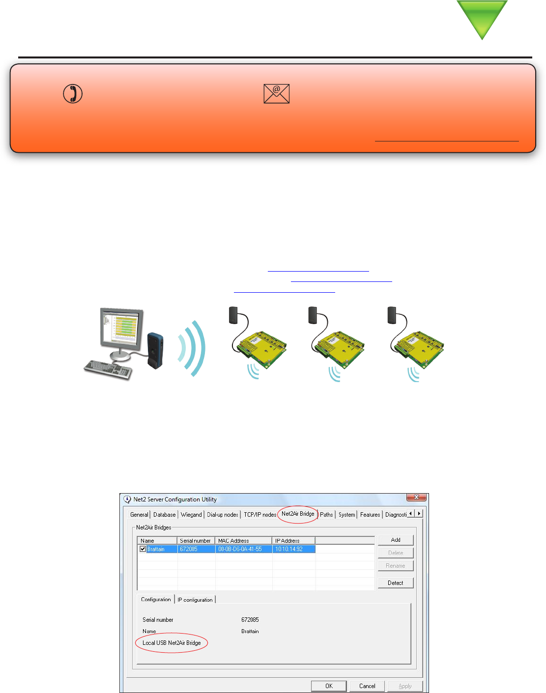
Plug the device into a spare USB port on the PC. The bridge will be registered by the Net2 software automatically.
This displays in the Net2 Server Conguration Utility/Net2Air bridge as a xed IP entry.
NOTE: Only ONE Net2Air USB bridge can be congured per system. Multiple
Net2Air Ethernet bridges may also be congured, up to 50 bridge nodes in total.
Reader
Control unit
Net2Air USB bridge
Net2 nano is a wireless based 1 door access control unit. It is recommended that a
Net2Air site surveyor is used to determine the best position for the bridge and units.
This device complies with Part 15 of the FCC Rules. Operation is subject to the following two conditions:
(1) this device may not cause harmful interference, and (2) this device must accept any interference
received, including interference that may cause undesired operation. Changes or modications not expressly
approved by the party responsible for compliance could void the user’s authority to operate the equipment.
1 10
1
2.4 GHz
30 m
4.75 V 5.25 V
150 mA
-20 °C 55 °C
70 mm 195 mm 100 mm
Specications
Carrier frequency
Environment
Dimensions
Min Max
Width Height Length
System Specication
Voltage
Electrical
Current
Waterproof
Min Max
Min Max
ACUs per Net2Air bridge
No
Net2Air USB bridge per system
Operating temperature
Net2Air wireless range to ACU
USB certied
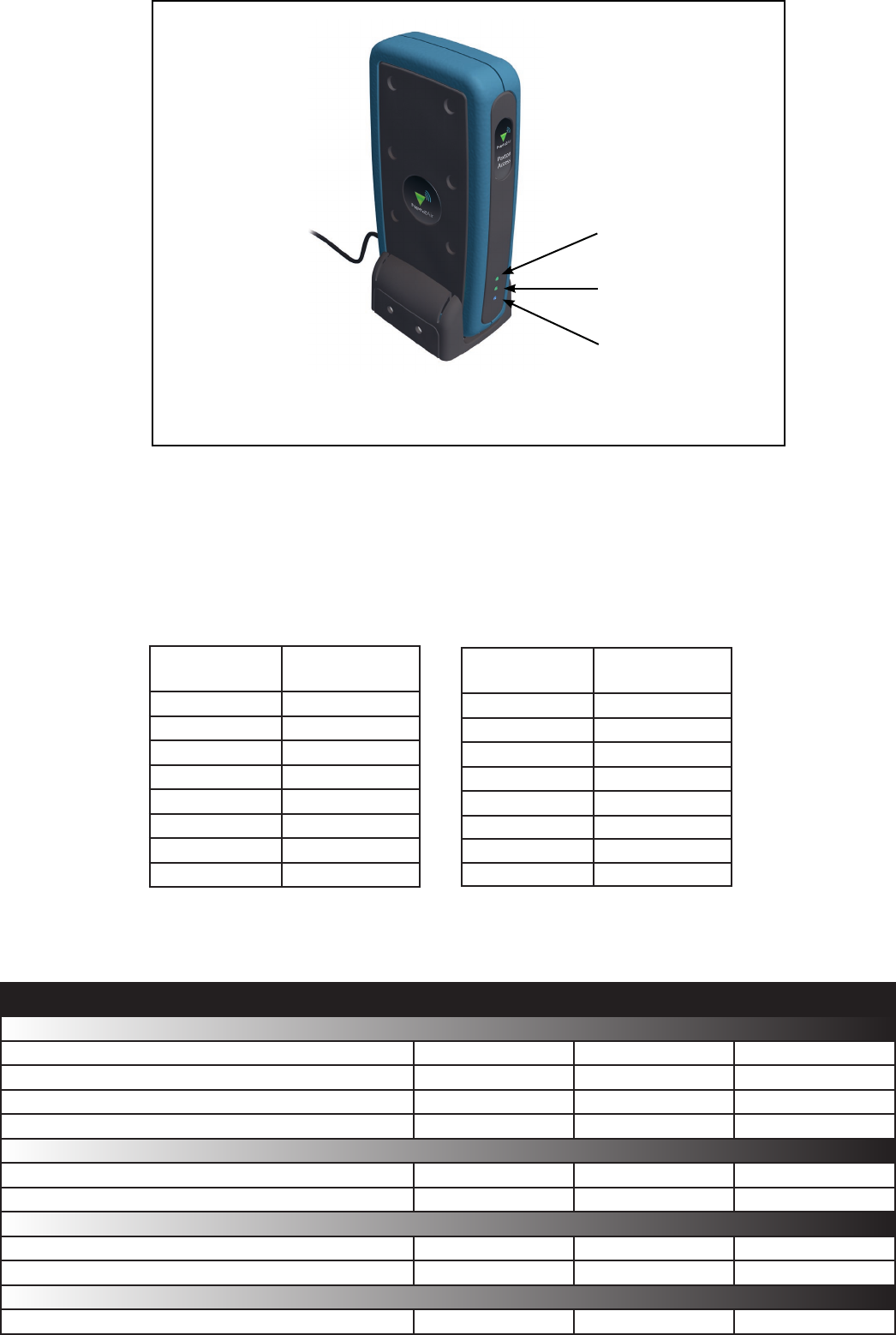
Layout
Changing frequency channel
If you are experiencing problems with the range or reliability this may be due to poor nano / bridge positioning
or adjacent interfering 2.4 GHz equipment, e.g. an adjacent wireless PC network.
The system has fteen different channels available. The unit is set to channel 11 as this frequency is normally
clear of other device transmissions.
Technical support can advise how to change the channel if interference is the cause of the problem.
11 2.405
12 2.41
13 2.415
14 2.42
15 2.425
16 2.43
17 2.435
18 2.44
GHz
IEEE 802.15.4
channel
19 2.445
20 2.45
21 2.455
22 2.46
23 2.465
24 2.47
25 2.475
IEEE 802.15.4
channel
GHz
USB connection
cable
Power
USB activity
Net2Air activity
The bridge should be mounted vertically in the
supplied base to achieve the optimum range
This equipment complies with FCC radiation exposure limits set forth for use in a
General Population/ Uncontrolled environment. This equipment should be operated
with a minimum distance of 20cm between the radiator and your body.