Pepperl Fuchs IUHF190V1B UHF RFID read/write device User Manual DOCT 2945J
Pepperl + Fuchs Inc UHF RFID read/write device DOCT 2945J
UserManual.wiki
>
Pepperl Fuchs
>
IUHF190V1B User Manual
user manual
Navigation menu
Upload a User Manual
Namespaces
Wiki Guide
HTML
PDF
Info
Views
User Manual
Discussion / Help
Navigation
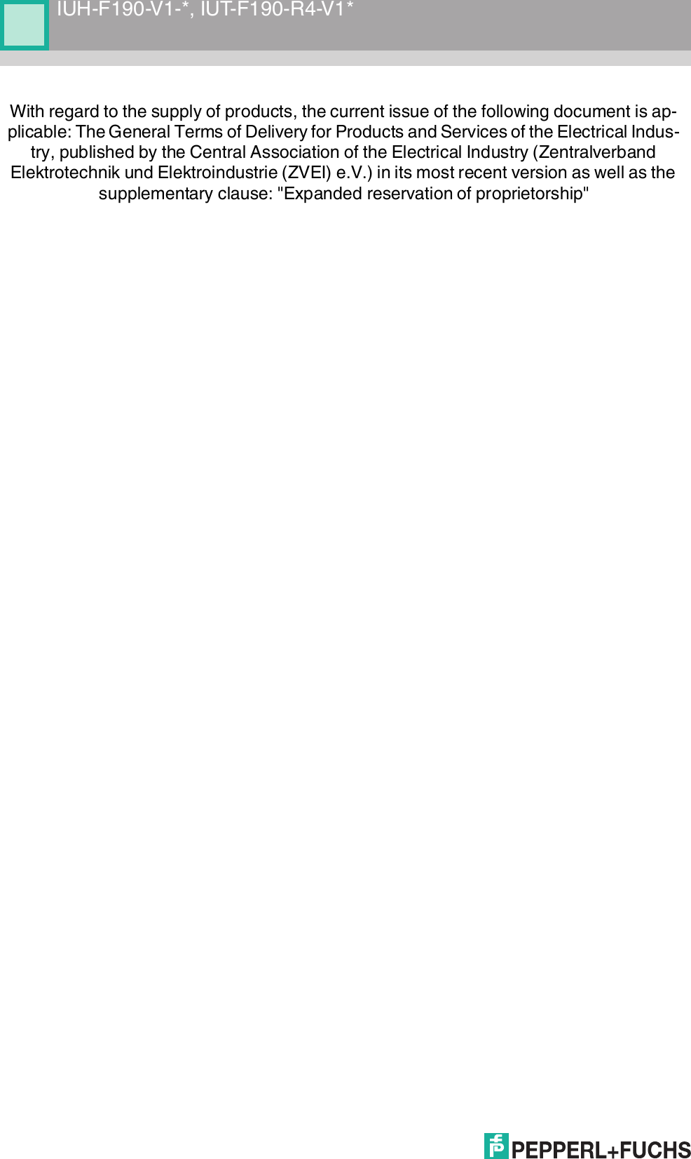
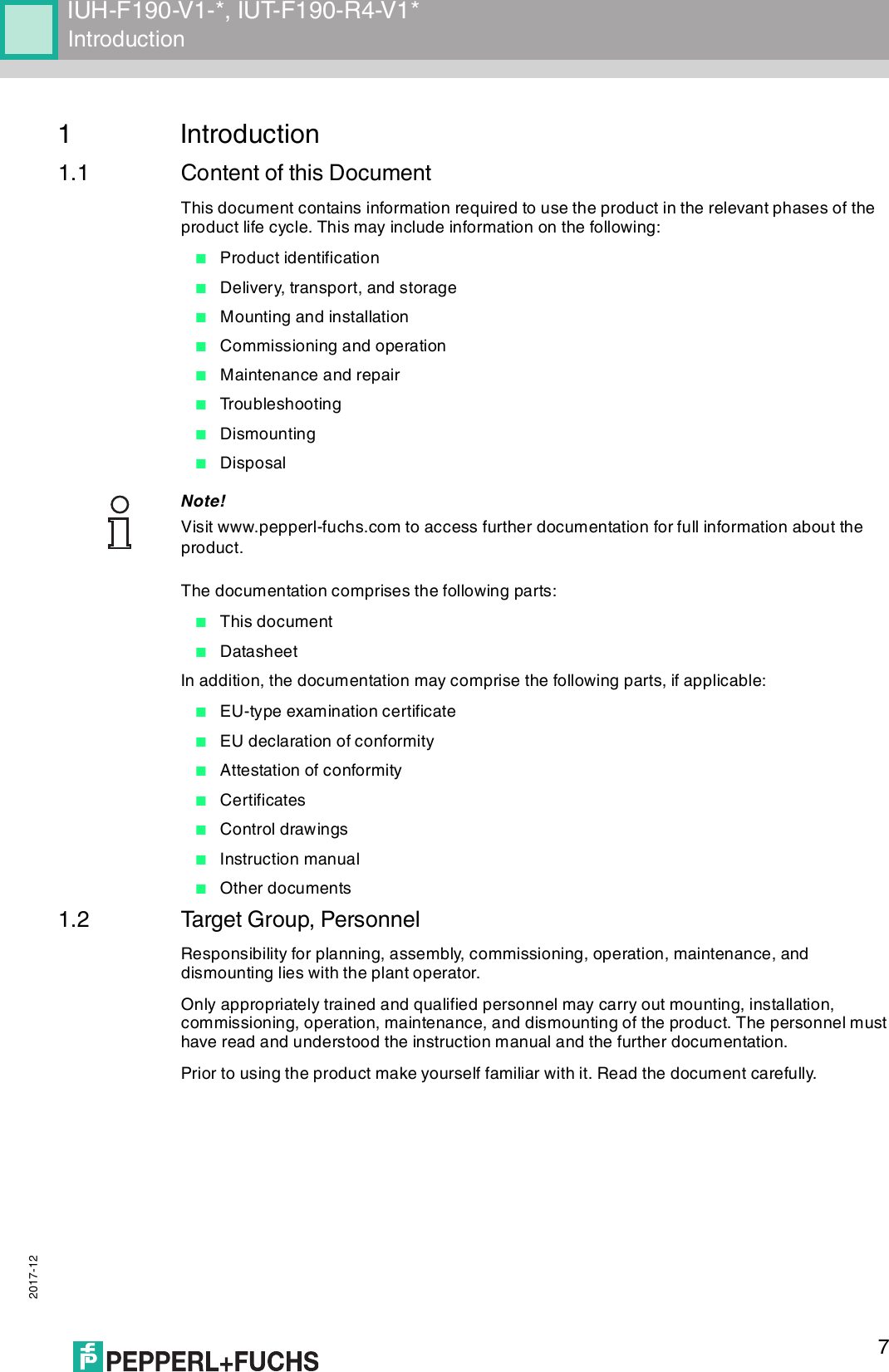
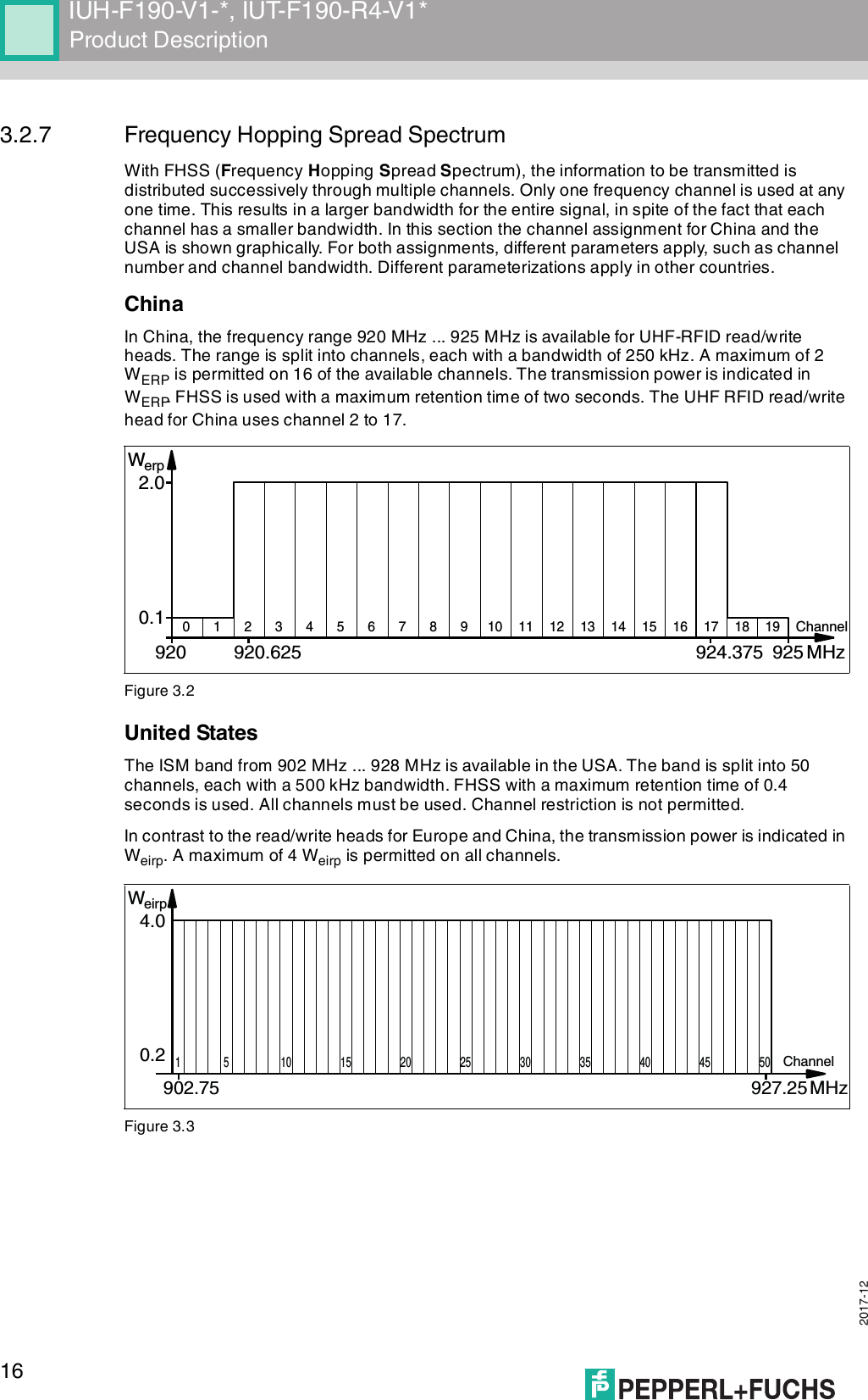
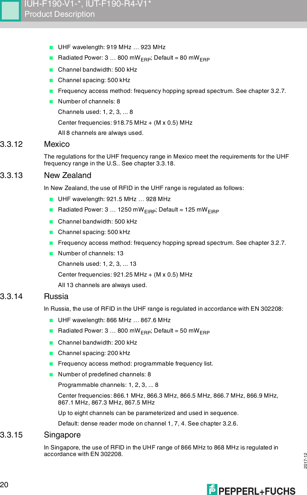
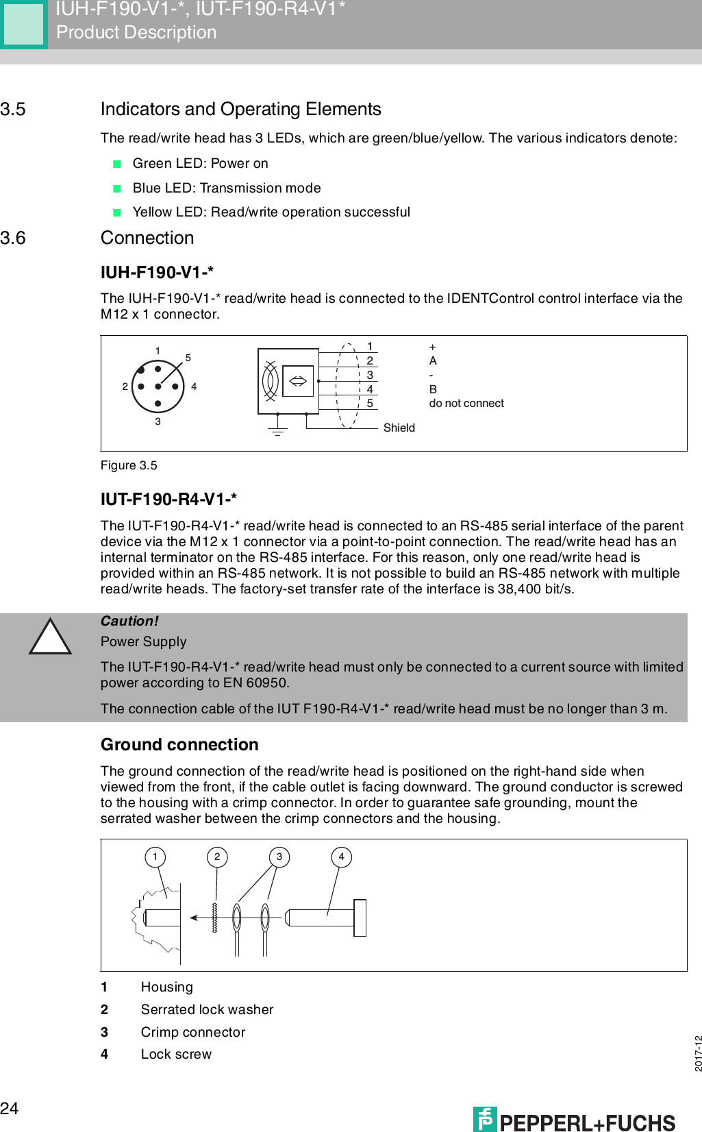
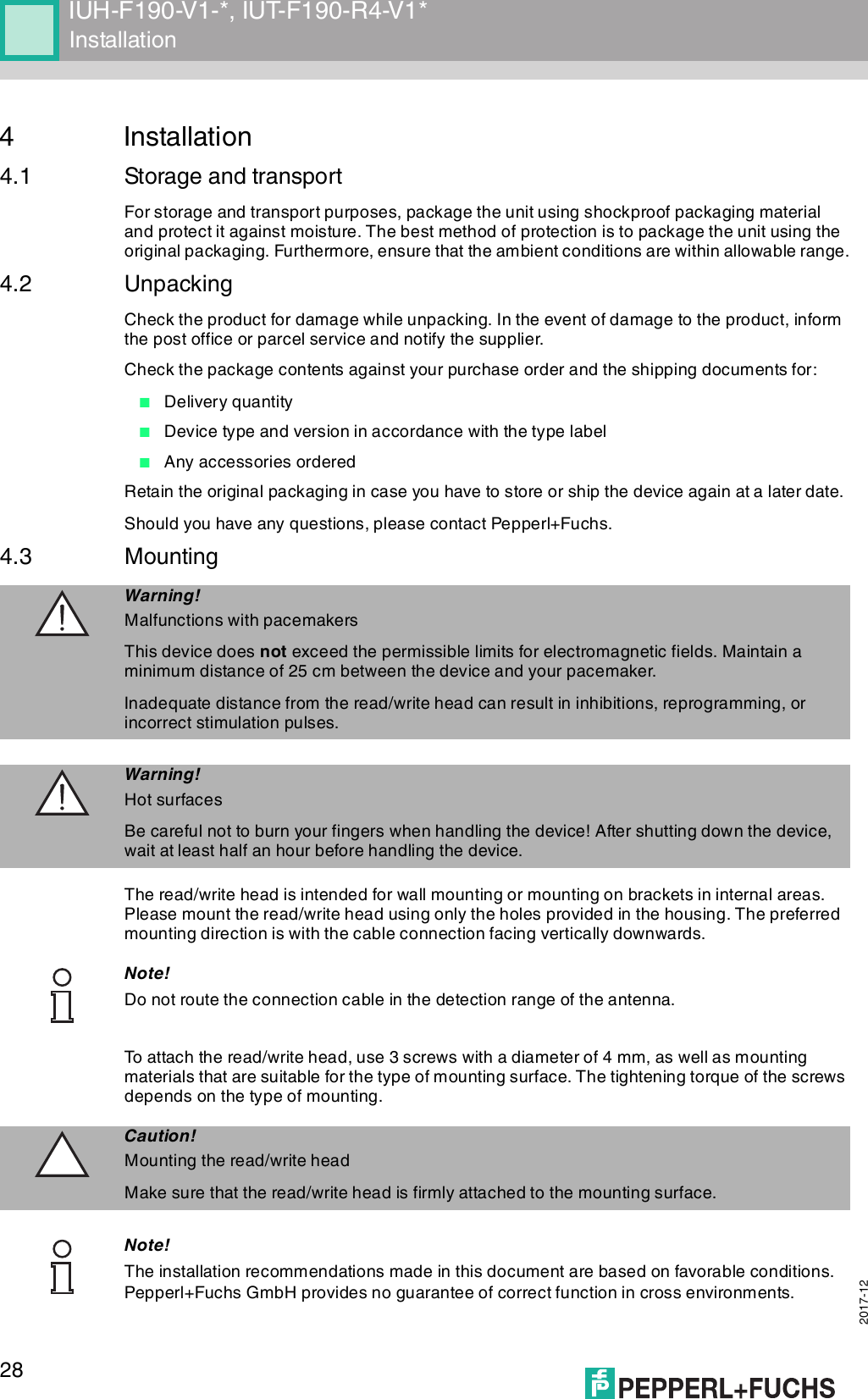
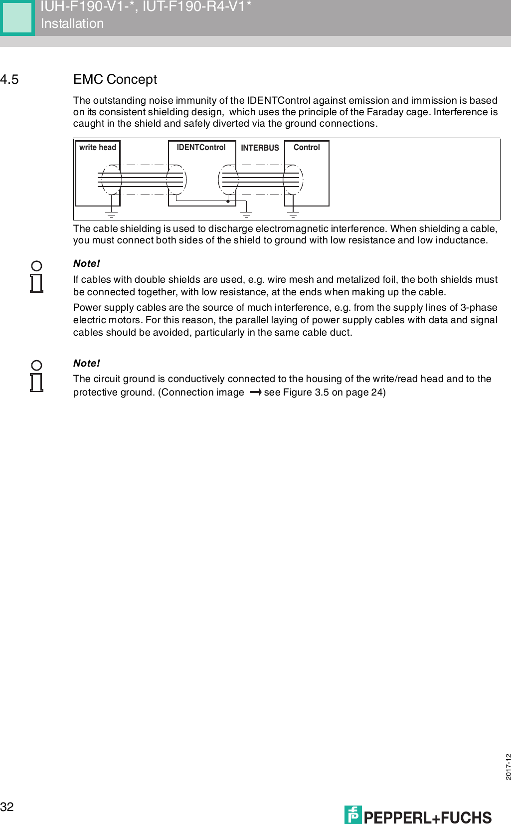
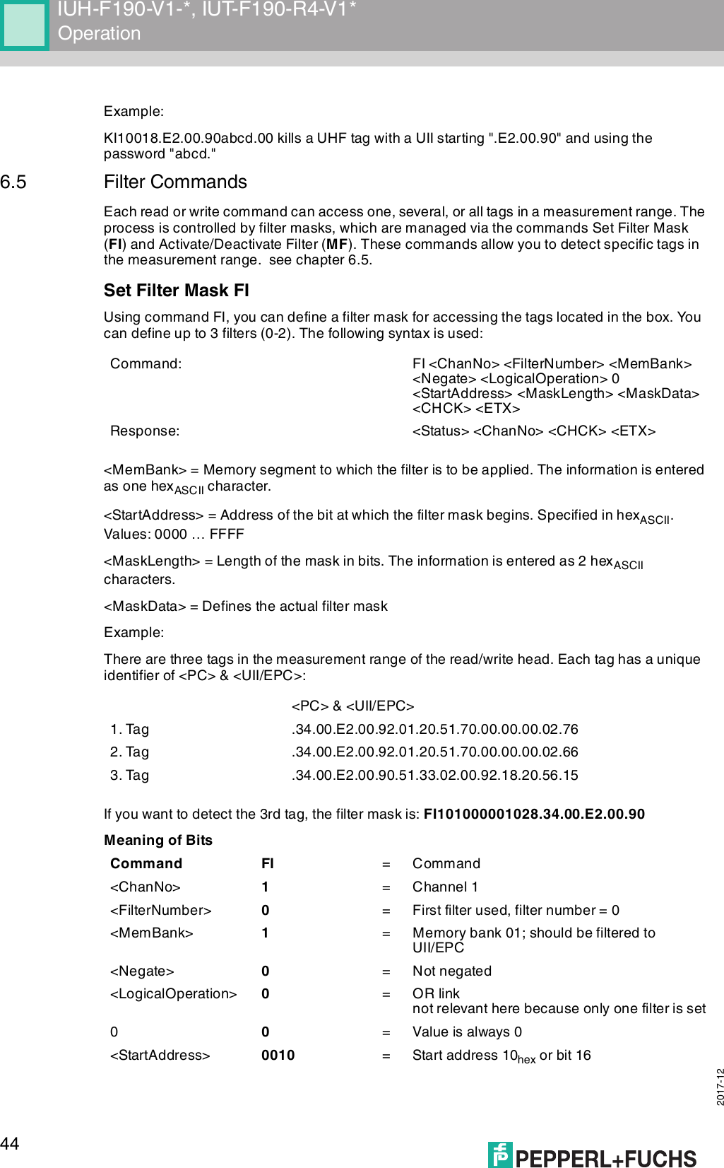
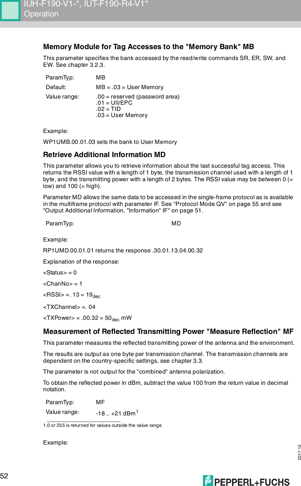
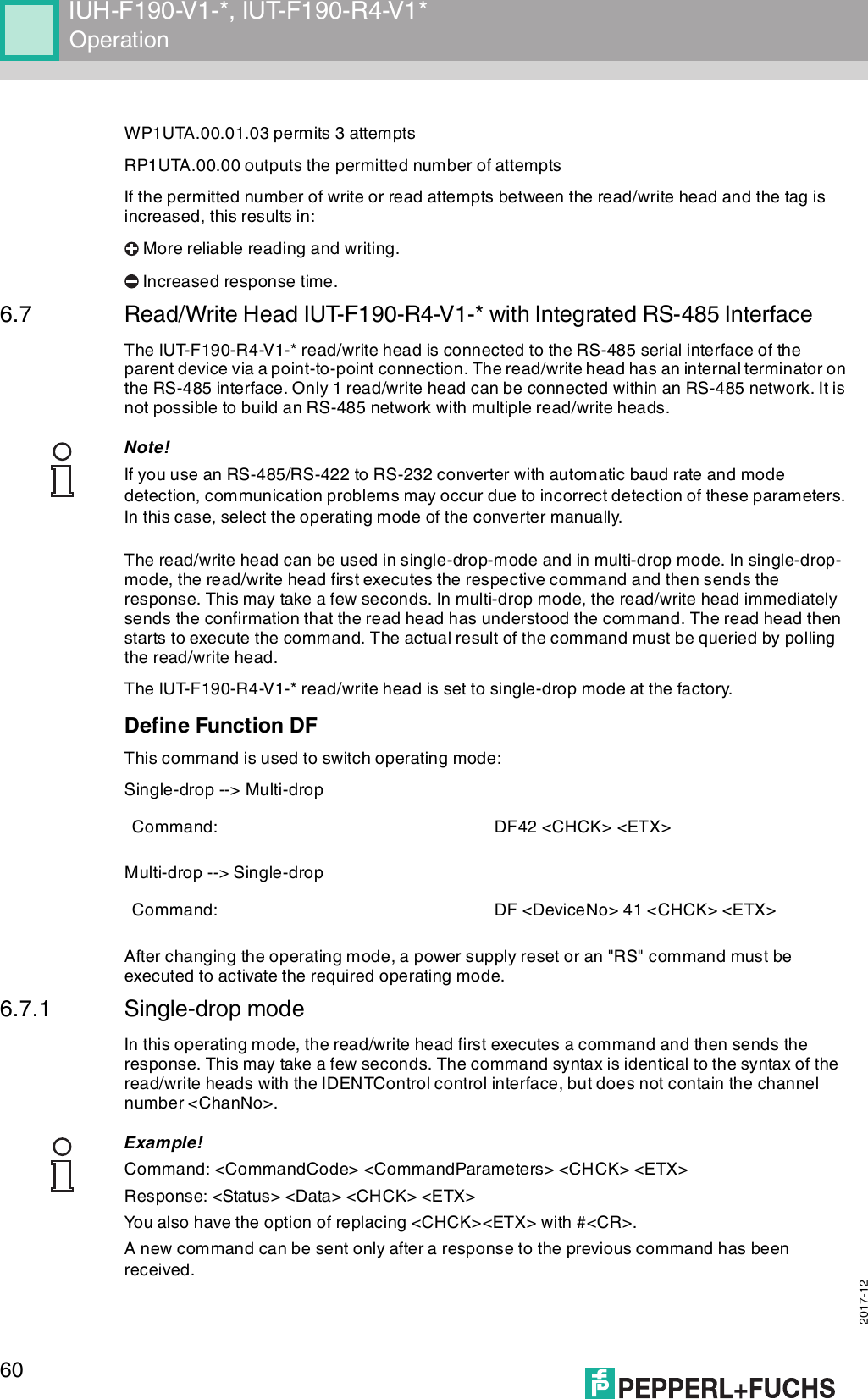
![IUH-F190-V1-*, IUT-F190-R4-V1*Product Description 2017-12113 Product Description3.1 RFID Frequency BandsThe following diagram shows the position of the different frequency bands used for RFID. The read/write heads described in this manual operate in the frequency range from 865 MHz ... 868 MHz and from 902 MHz ... 928 MHz, highlighted in color. ■100 kHz ... 135 kHz: Low frequency LF■13.56 MHz: High frequency HF■865 MHz ... 868 MHz (Europe), 902 MHz ... 928 MHz (USA), 920 MHz ... 925 MHz (China): ultra-high frequency UHF■2.45 GHz and 5.8 GHz: Microwave MW3.2 UHF general3.2.1 Advantages of UHF■Long detection range■UHF tags are available as cheap and space-saving adhesive labels■High transfer rates■Tag is available with a large working memory (user memory)■Bulk detection3.2.2 Applications for UHF systems■Identification in galvanic coating or painting systems used in automotive production,■Identification feasible over greater distances than with LF and HF systems,■Identification of automotive superstructures in automotive production,■Pallet identification and measurement of goods movements in the logistics sector, and■Access control at unloading stations with HGV identification.Frequency[MhZ]125 kHz2,45 GHz13,56 MHz5,8 GHz868/915 MHz0,1LF1 10HF100 1000UHF10000MW](https://usermanual.wiki/Pepperl-Fuchs/IUHF190V1B/User-Guide-3675252-Page-11.png)
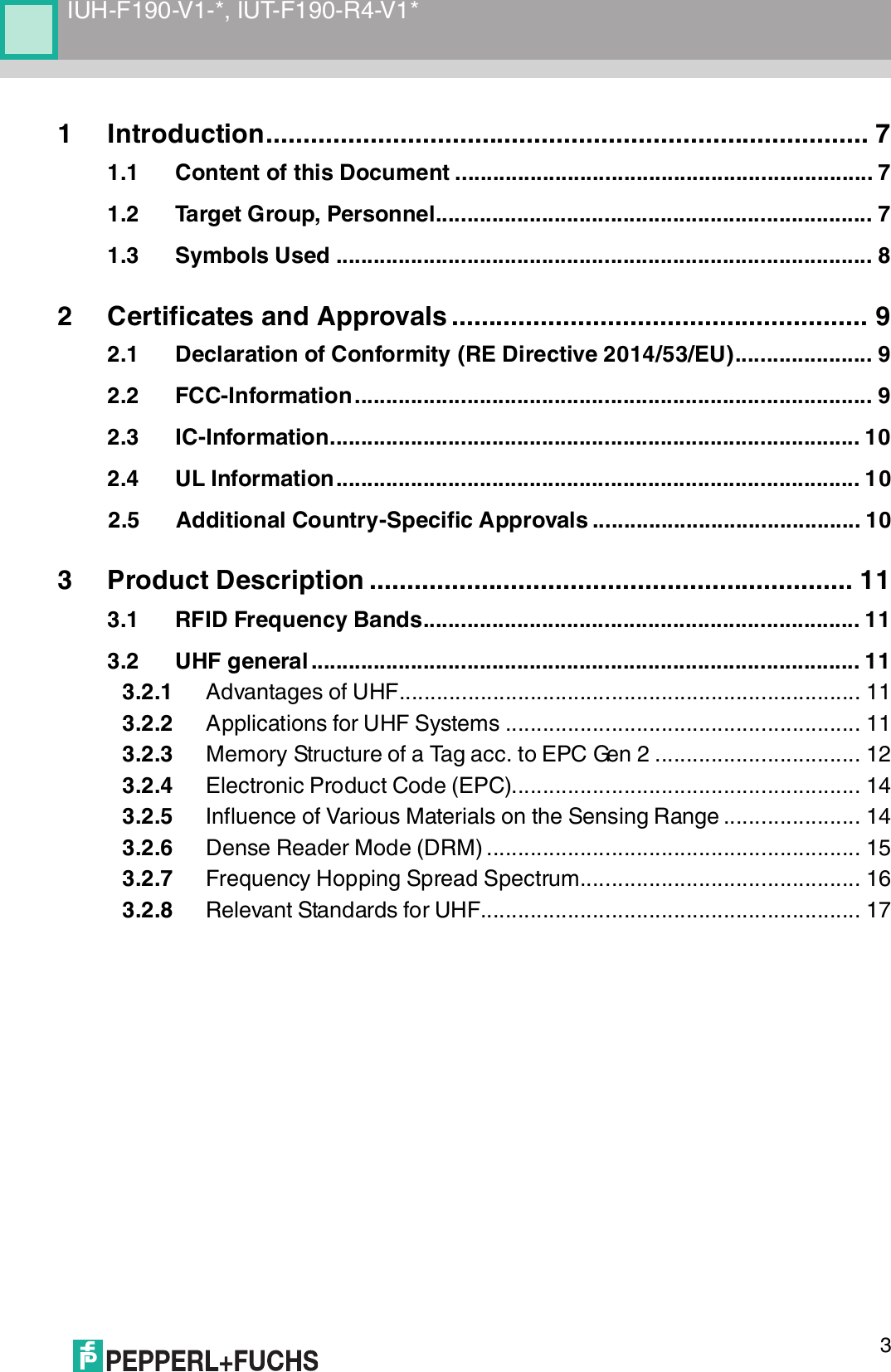
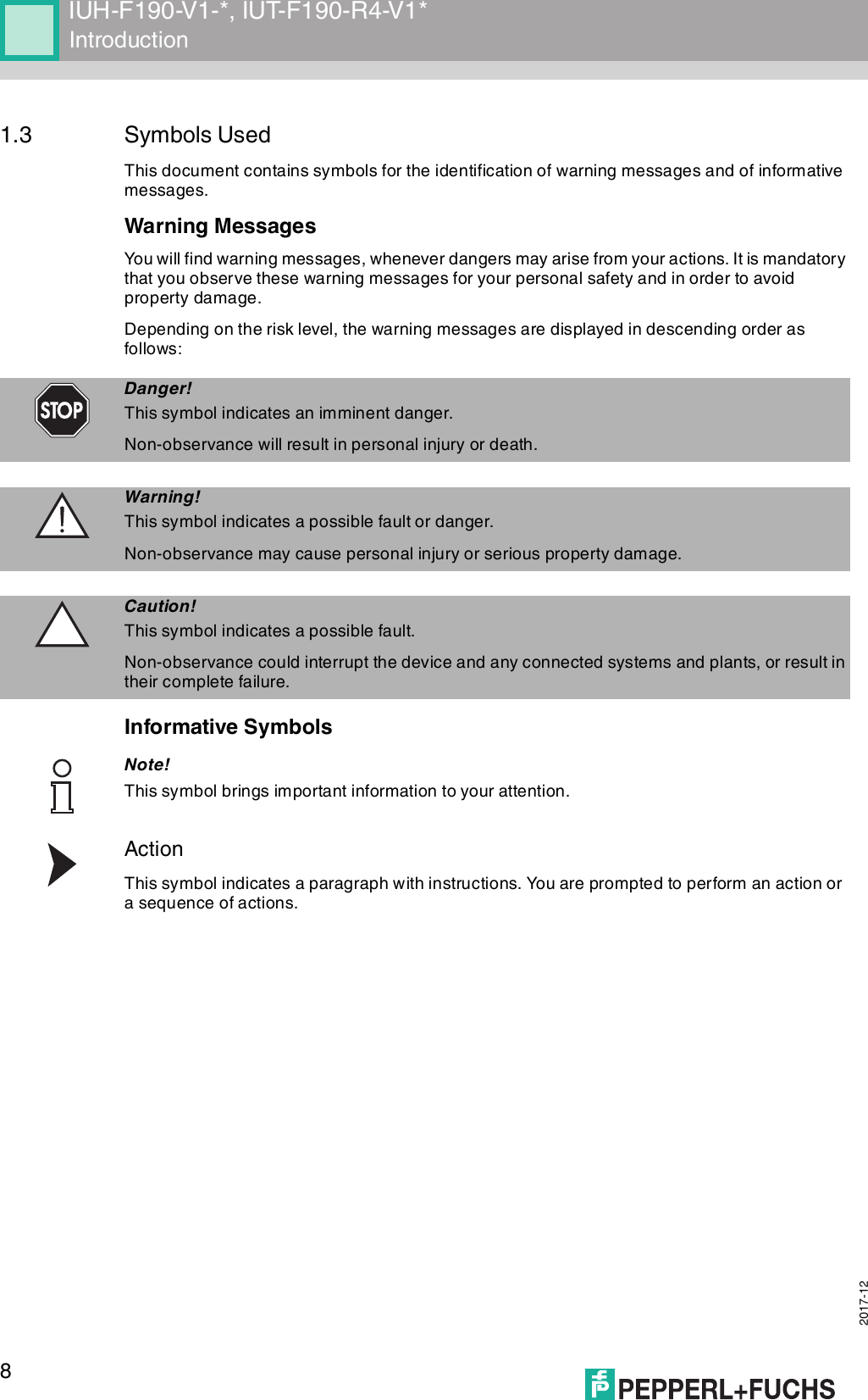
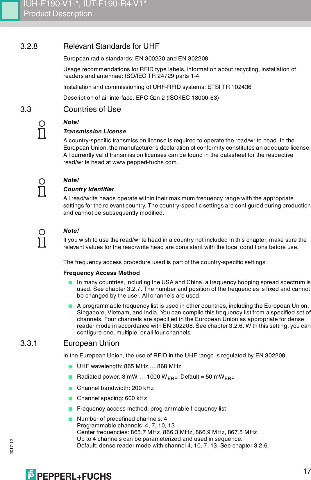
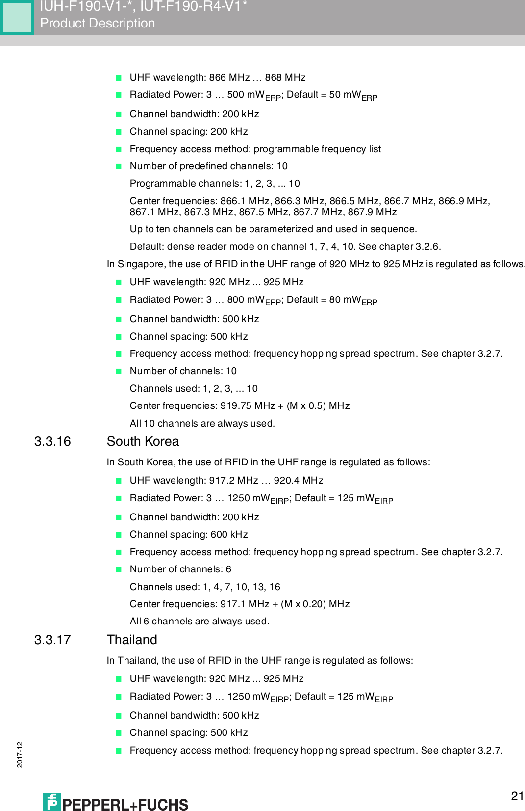
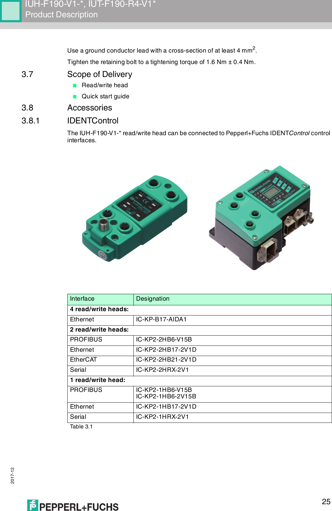
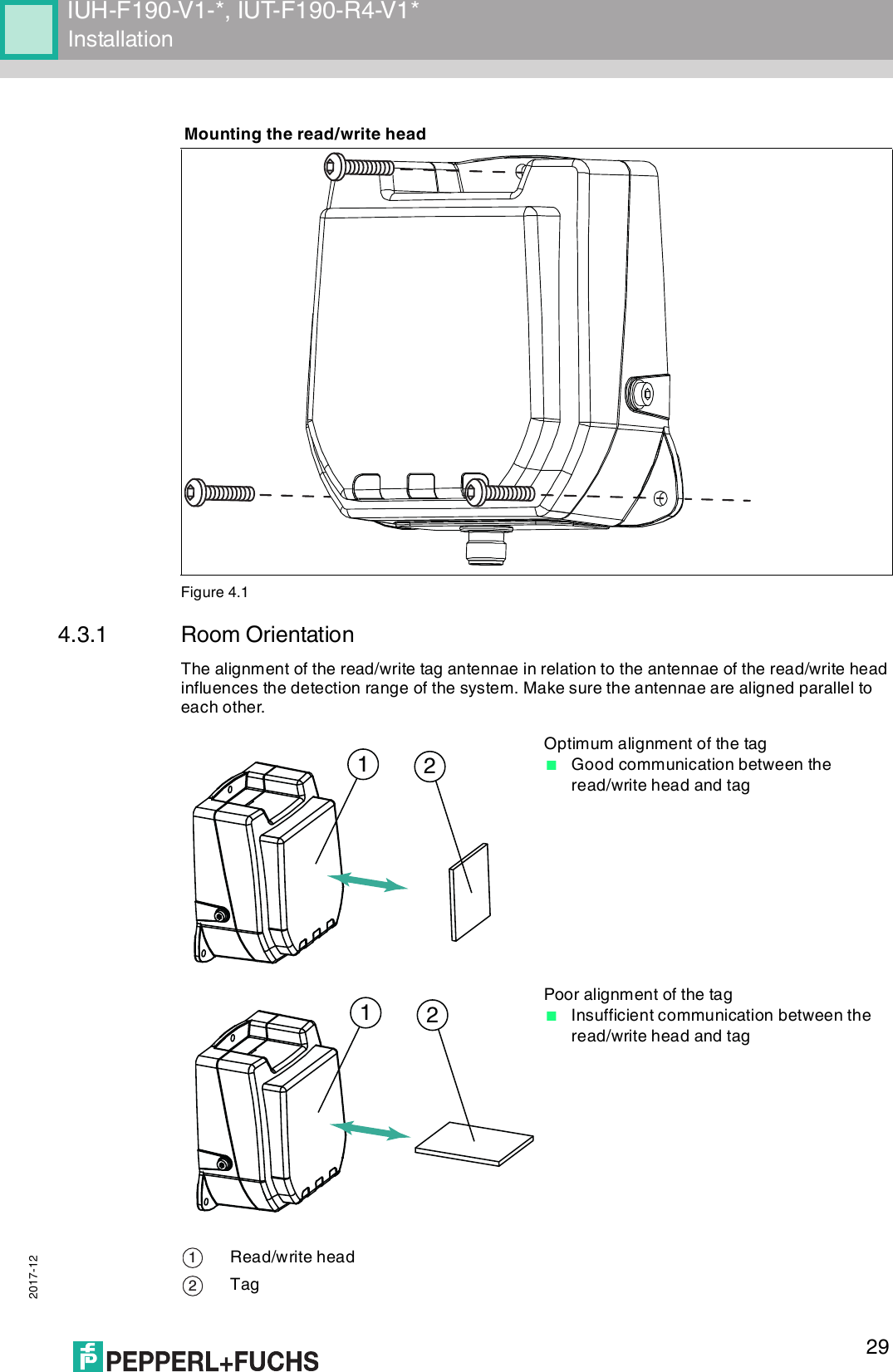
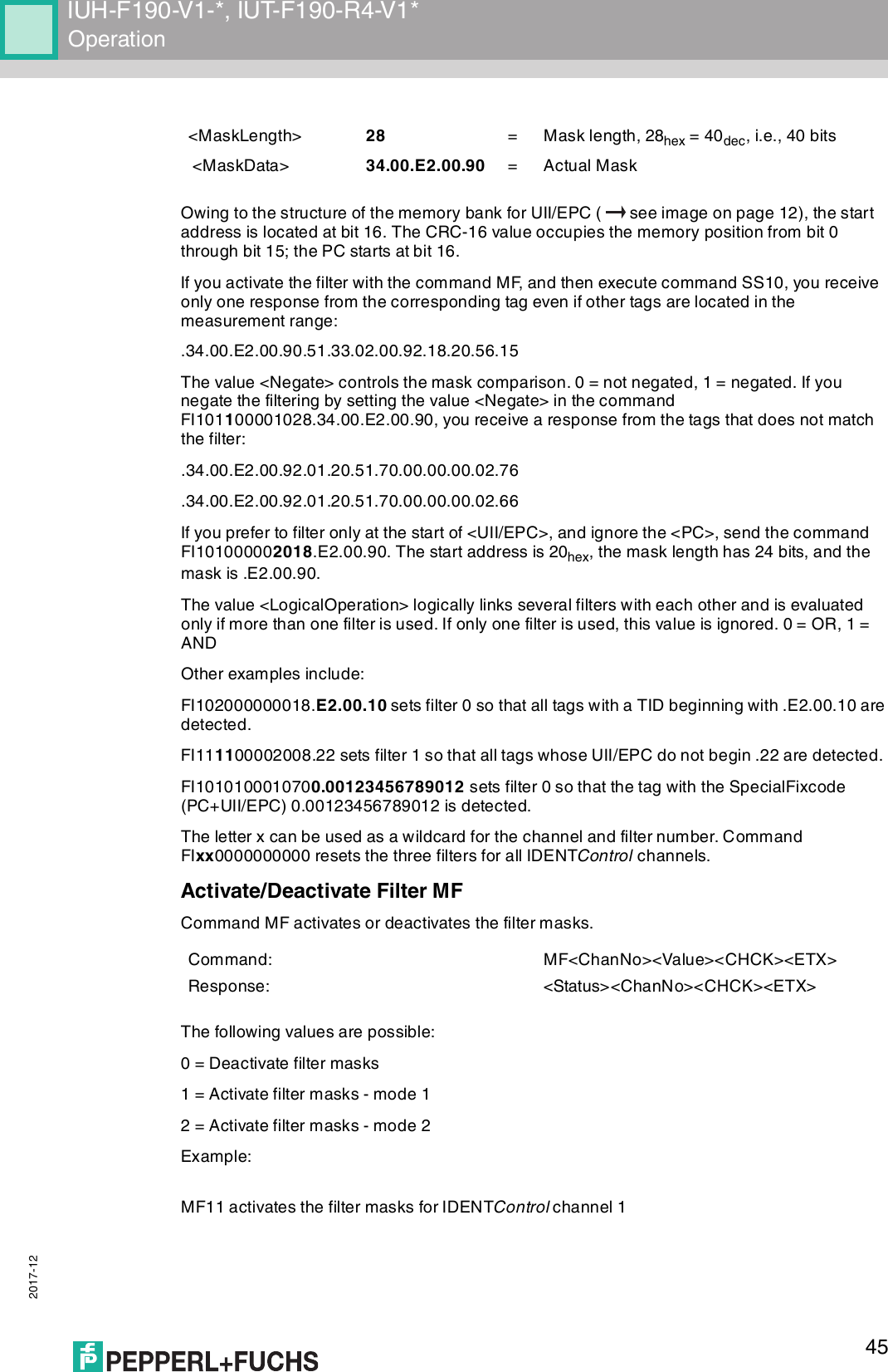
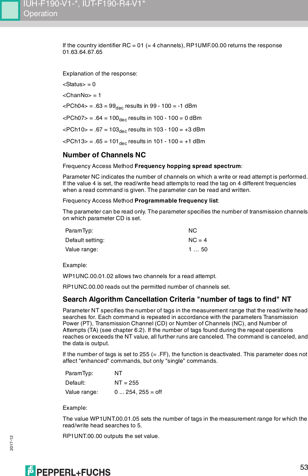
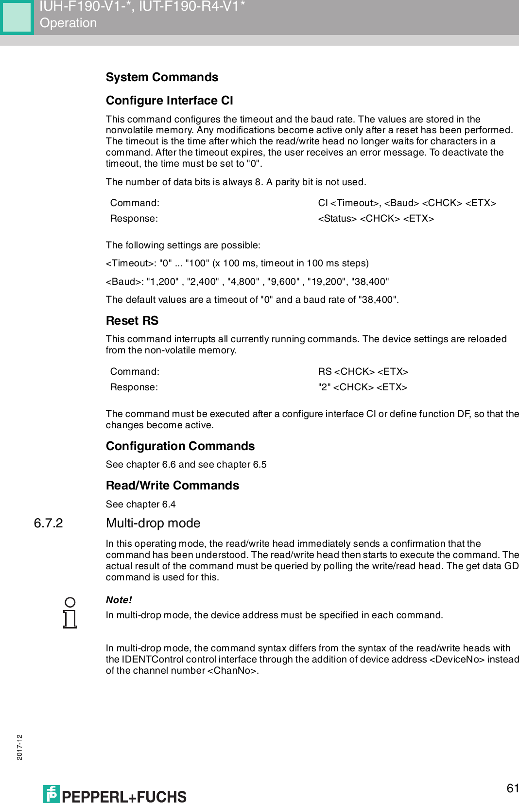
![2017-1212IUH-F190-V1-*, IUT-F190-R4-V1*Product Description3.2.3 Memory Structure of a Tag in Accordance with EPC Gen 2 (ISO/IEC 18000-63)The memory module of an EPC Gen 2 (ISO/IEC 18000-63) tag is split into four segments. The main contents of these segments are:Segment Function LengthBank 00(00bin = 0dec)Password managementDepending on the tag type, /column "Bank 00"Bank 01(01bin = 1dec)Unique Item Identifier (UII)Electronic Product Code (EPC)Depending on the tag type, /column "UII/EPC"Bank 10(10bin = 2dec)Tag ID (TID) 4 bytes (MDID, TMN) + 0, 4, or 8 bytesBank 11(11bin = 3dec)User memory Depending on the tag type, /column "User Data"USERTIDUII/EPCRESERVEDRFU [7:0]10h1Fh...MSB LSBDSFID [7:0]00h0FhTID [15:0]10h1Fh...MSB LSBTID [31:16]00h0FhUII/EPC [N:N-15]20h210h2Fh...MSB LSBPC [15:0]10h1FhUII/EPC [15:0]CRC-16 [15:0]00h0FhAccess Password [15:0]30h3Fh...MSB LSBAccess Password [31:16]20h2FhKill Password [15:0]10h1FhKill Password [31:16]00h0FhBank 11Bank 10Bank 01Bank 00SR/ERSW/EWSS/ESSPSF/EF...Optional XPC_W2 [15:0]Optional XPC_W2 [15:0]...220h21Fh22FhMemory moduleCommandsRead / write head](https://usermanual.wiki/Pepperl-Fuchs/IUHF190V1B/User-Guide-3675252-Page-12.png)
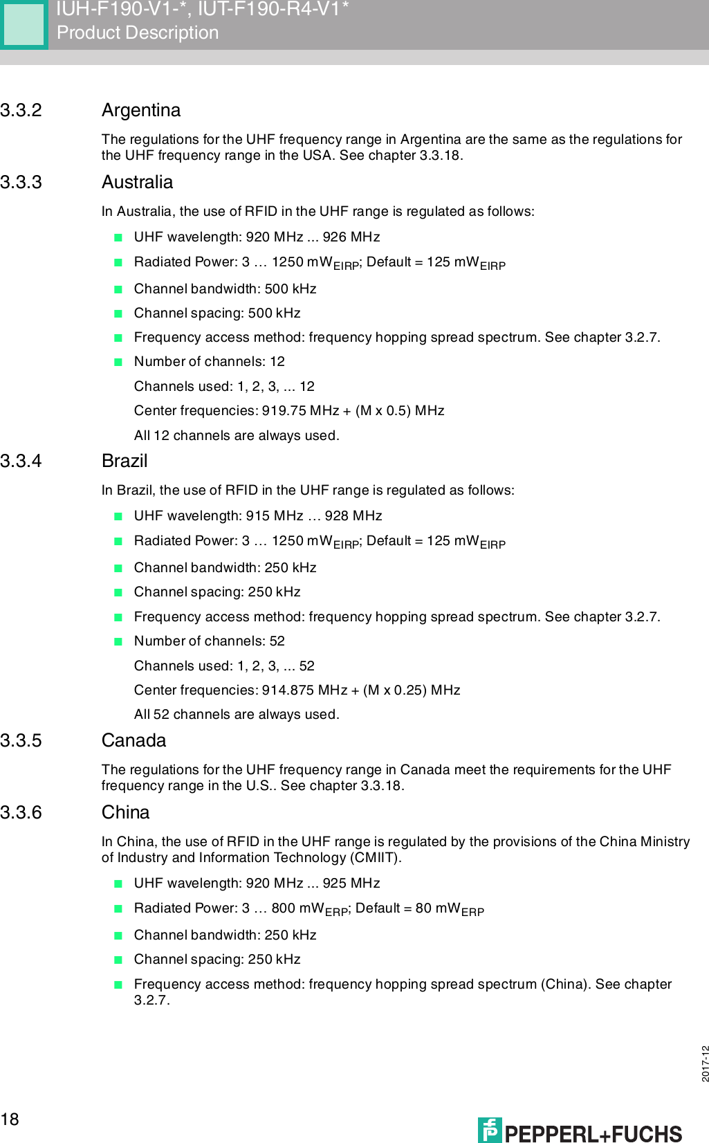
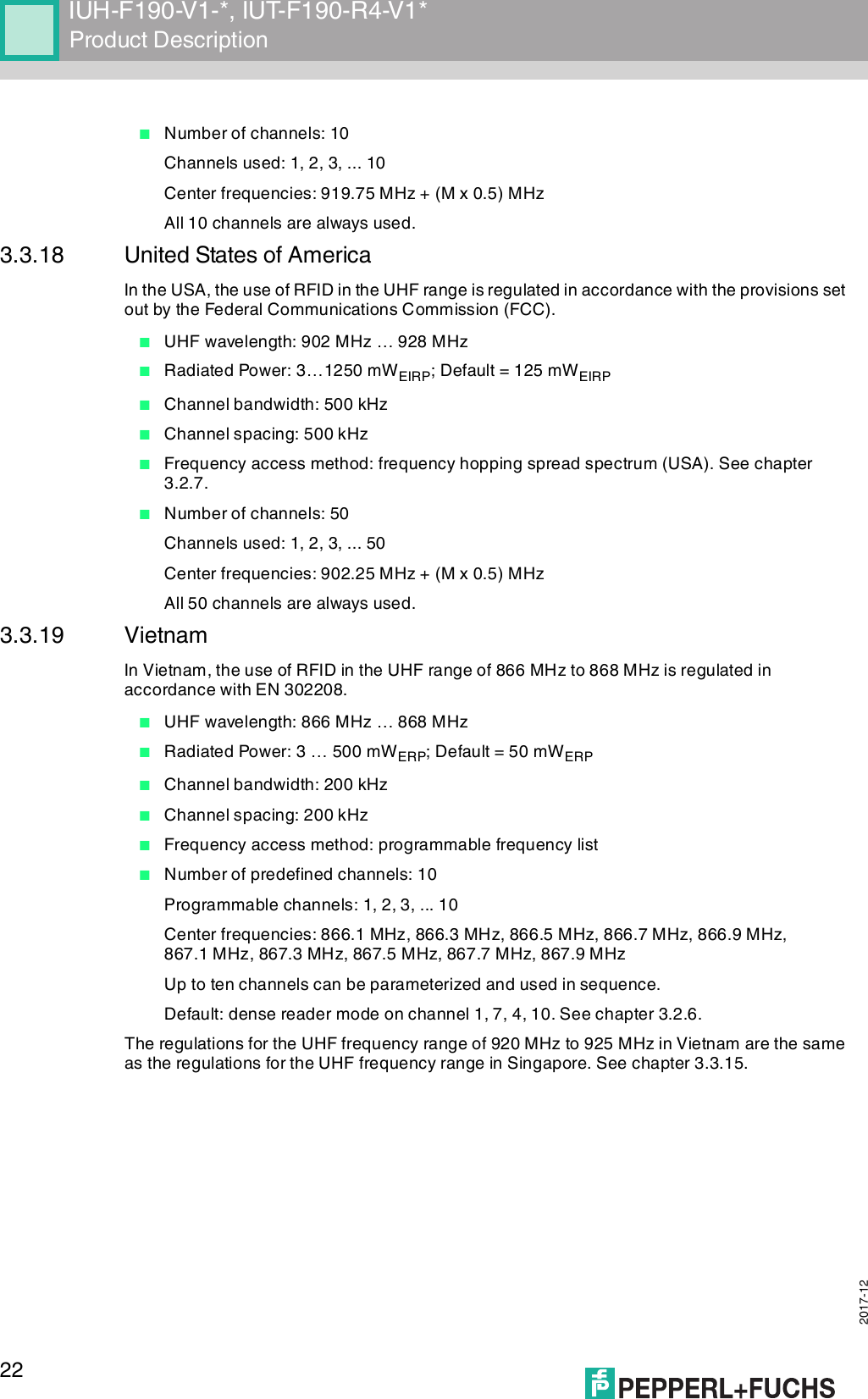
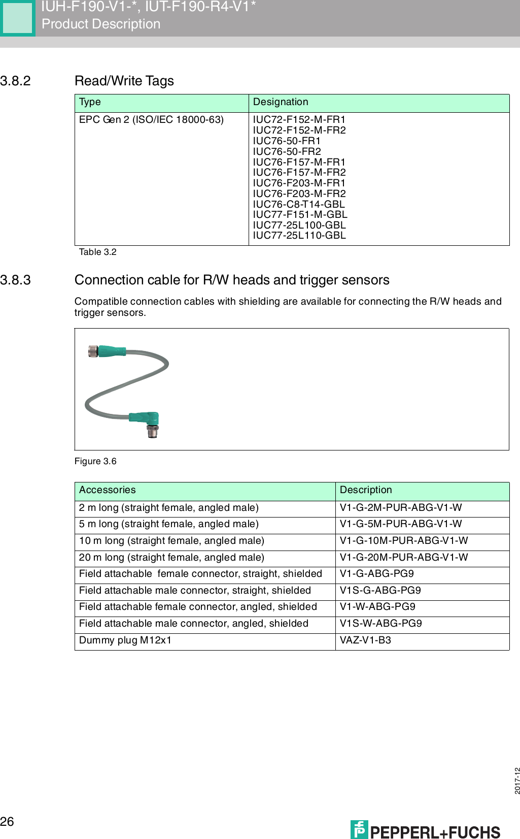
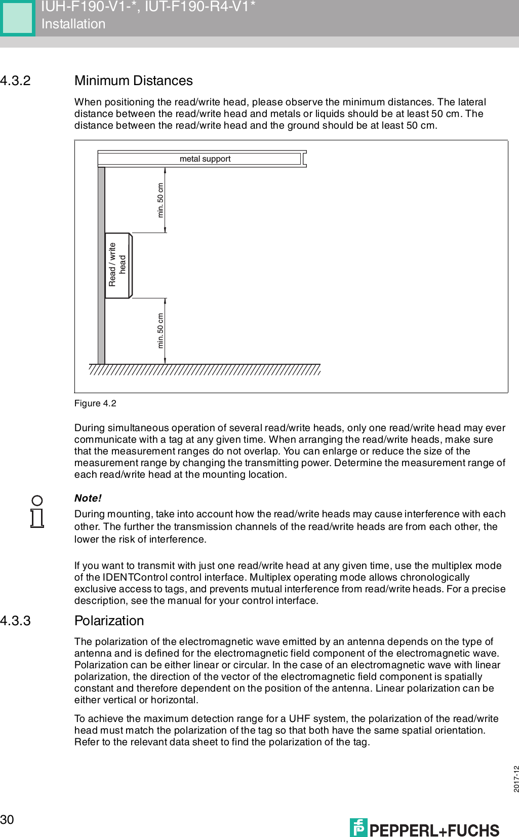
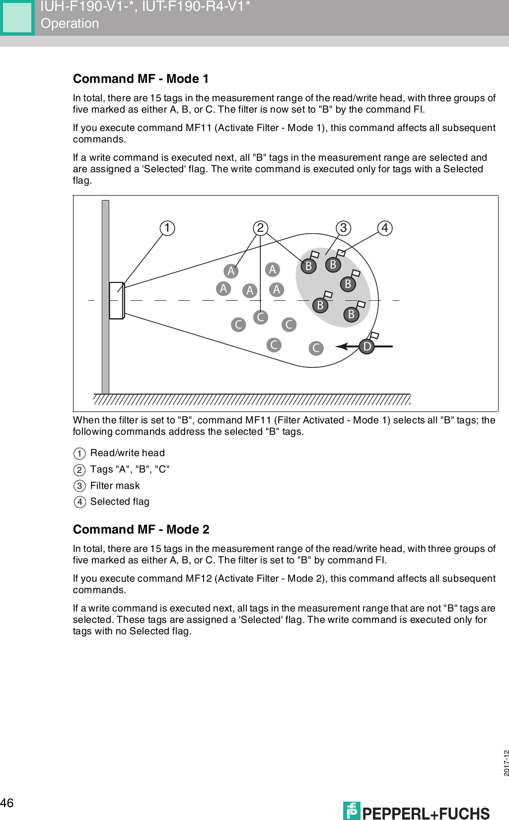
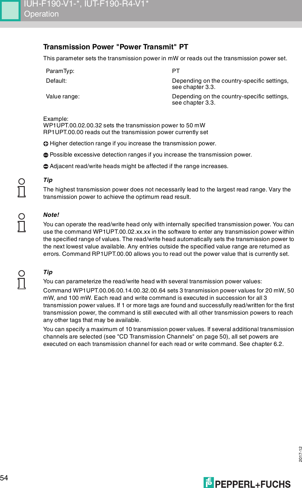
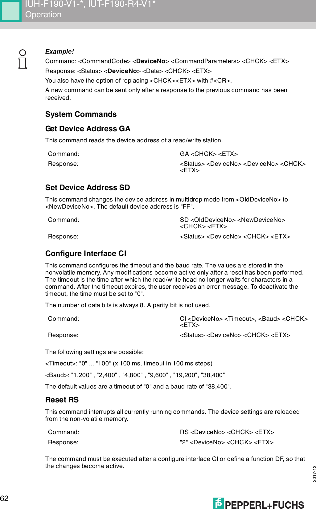
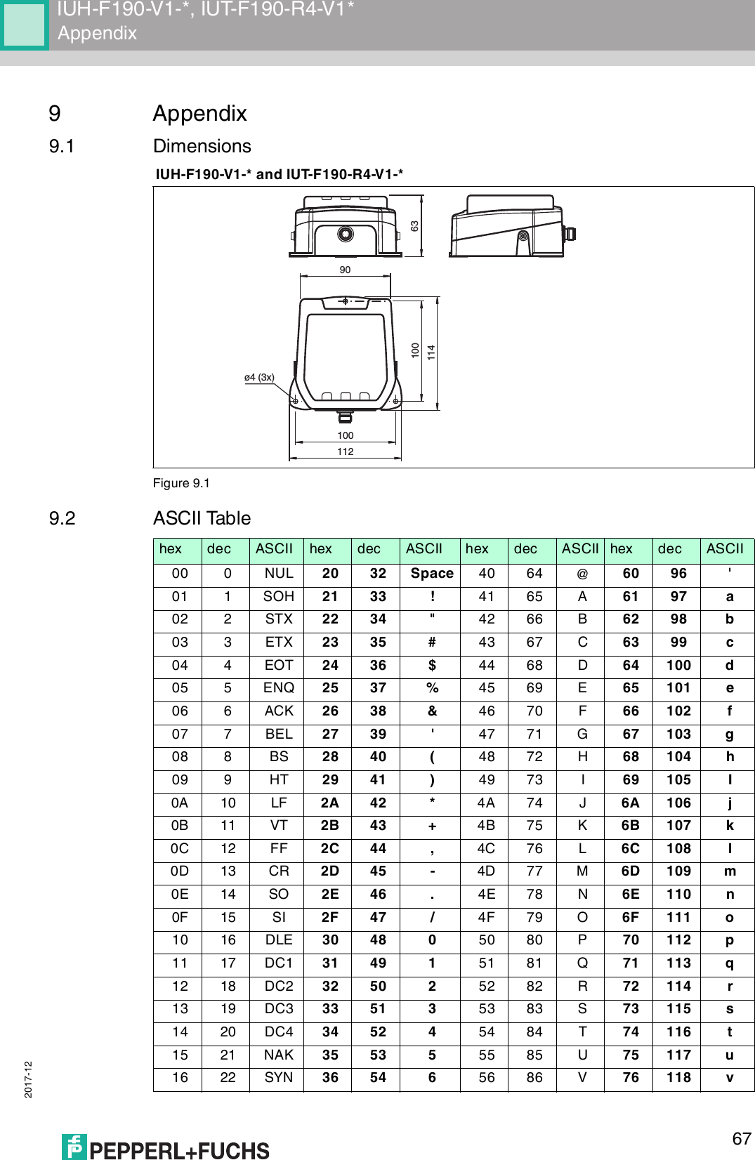
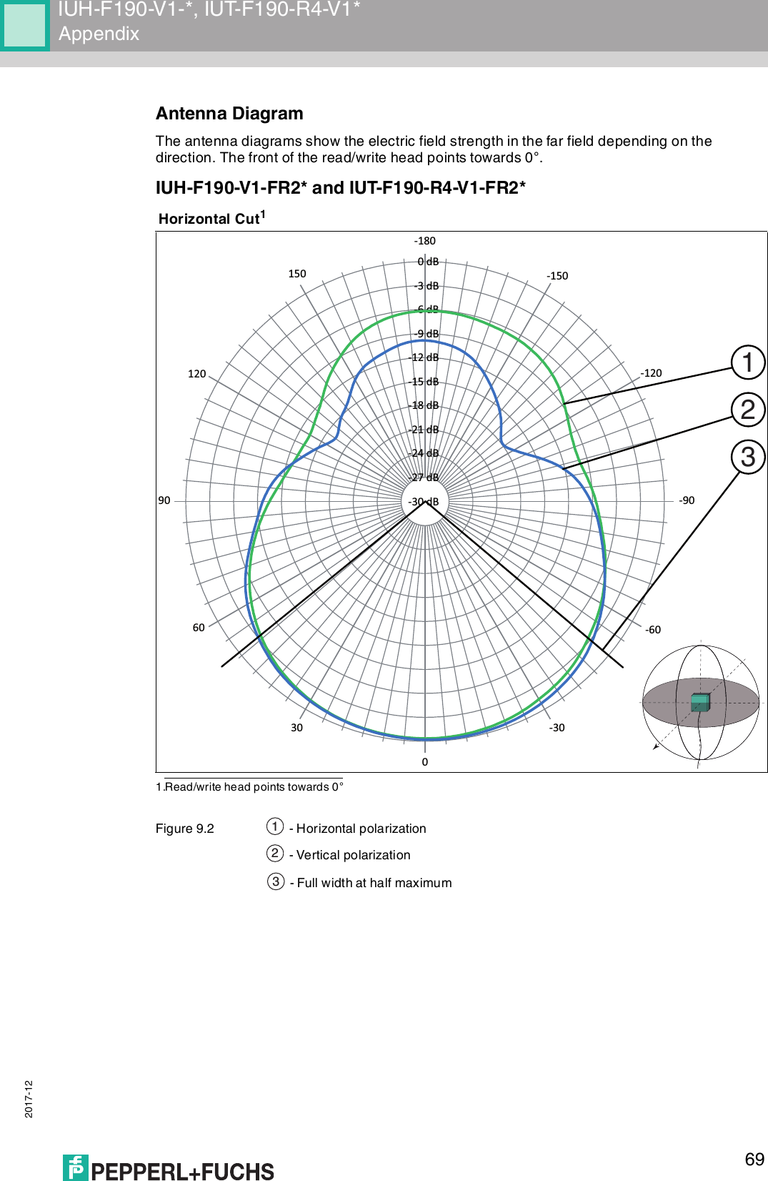
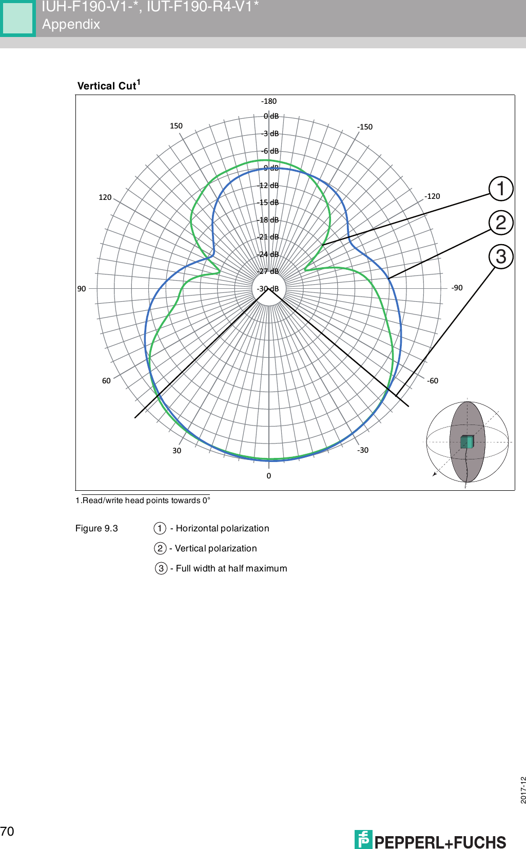
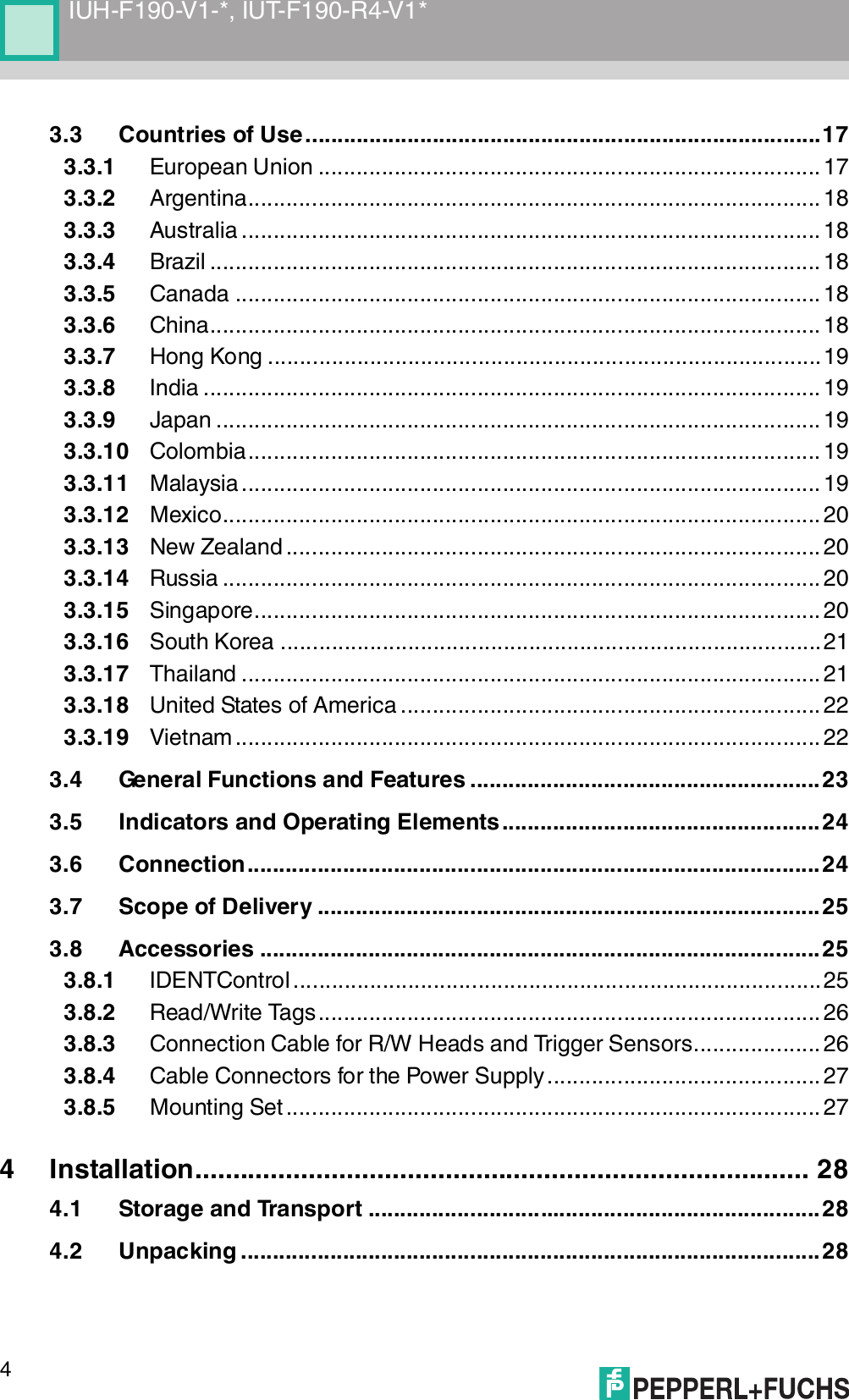
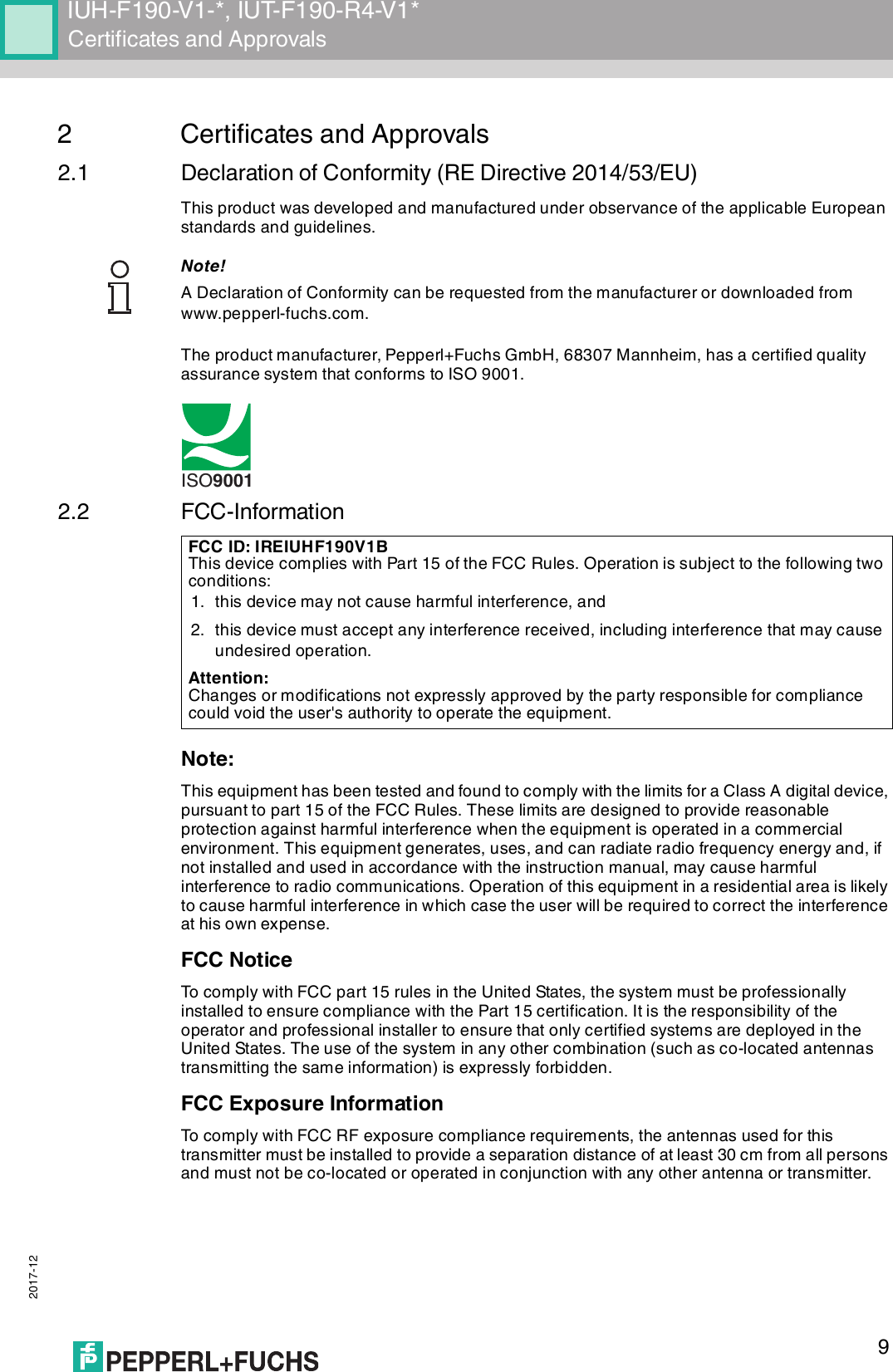
![2017-1268IUH-F190-V1-*, IUT-F190-R4-V1*Appendix9.3 Detection RangeThe read/write head has a typical detection range of around 1 meter; this range is determined by the tag used and can be adjusted by selecting the transmission power. Other influencing factors include the setup and installation of the specific application, interference from any materials present (in particular metal), and the ambient conditions. The read and write distances for the relevant tag, which are detailed separately, have been established in a test laboratory under ideal conditions. For this reason, the combination of read/write head and tag must be tested for the intended application under real conditions.Please note the distance tables. The distance tables and additional information regarding your product can be found at http://www.pepperl-fuchs.com. Simply enter the product name or model number in the Search box and then click the Search key.Select your product from the list of search results. Click on the information you require in the product information list, e.g., Technical documents.A list of all available documents is displayed.17 23 ETB 37 55 7 57 87 W 77 119 w18 24 CAN 38 56 8 58 88 X 78 120 x19 25 EM 39 57 9 59 89 Y 79 121 y1A 26 SUB 3A 58 : 5A 90 Z 7A 122 z1B 27 ESC 3B 59 ; 5B 91 [ 7B 123 {1C 28 FS 3C 60 < 5C 92 \ 7C 124 |1D 29 GS 3D 61 = 5D 93 ] 7D 125 }1E 30 RS 3E 62 > 5E 94 ^ 7E 126 ~1F 31 US 3F 63 ? 5F 95 _ 7F 127 DELhex dec ASCII hex dec ASCII hex dec ASCII hex dec ASCII](https://usermanual.wiki/Pepperl-Fuchs/IUHF190V1B/User-Guide-3675252-Page-68.png)