Pepperl Fuchs IUHF190V1B UHF RFID read/write device User Manual DOCT 2945J
Pepperl + Fuchs Inc UHF RFID read/write device DOCT 2945J
user manual
IUH-F190-V1-*
IUT-F190-R4-V1*
UHR Read/Write Head
for IDENTControl
FACTORY AUTOMATION
MANUAL

With regard to the supply of products, the current issue of the following document is ap-
plicable: The General Terms of Delivery for Products and Services of the Electrical Indus-
try, published by the Central Association of the Electrical Industry (Zentralverband
Elektrotechnik und Elektroindustrie (ZVEI) e.V.) in its most recent version as well as the
supplementary clause: "Expanded reservation of proprietorship"
IUH-F190-V1-*, IUT-F190-R4-V1*

IUH-F190-V1-*, IUT-F190-R4-V1*
3
1 Introduction................................................................................. 7
1.1 Content of this Document ................................................................... 7
1.2 Target Group, Personnel...................................................................... 7
1.3 Symbols Used ...................................................................................... 8
2 Certificates and Approvals ........................................................ 9
2.1 Declaration of Conformity (RE Directive 2014/53/EU)...................... 9
2.2 FCC-Information................................................................................... 9
2.3 IC-Information..................................................................................... 10
2.4 UL Information.................................................................................... 10
2.5 Additional Country-Specific Approvals ........................................... 10
3 Product Description ................................................................. 11
3.1 RFID Frequency Bands...................................................................... 11
3.2 UHF general ........................................................................................ 11
3.2.1 Advantages of UHF.......................................................................... 11
3.2.2 Applications for UHF Systems ......................................................... 11
3.2.3 Memory Structure of a Tag acc. to EPC Gen 2 ................................. 12
3.2.4 Electronic Product Code (EPC)........................................................ 14
3.2.5 Influence of Various Materials on the Sensing Range ...................... 14
3.2.6 Dense Reader Mode (DRM) ............................................................ 15
3.2.7 Frequency Hopping Spread Spectrum............................................. 16
3.2.8 Relevant Standards for UHF............................................................. 17

4
IUH-F190-V1-*, IUT-F190-R4-V1*
3.3 Countries of Use.................................................................................17
3.3.1 European Union ............................................................................... 17
3.3.2 Argentina.......................................................................................... 18
3.3.3 Australia ........................................................................................... 18
3.3.4 Brazil ................................................................................................ 18
3.3.5 Canada ............................................................................................ 18
3.3.6 China................................................................................................ 18
3.3.7 Hong Kong .......................................................................................19
3.3.8 India ................................................................................................. 19
3.3.9 Japan ............................................................................................... 19
3.3.10 Colombia.......................................................................................... 19
3.3.11 Malaysia ........................................................................................... 19
3.3.12 Mexico.............................................................................................. 20
3.3.13 New Zealand .................................................................................... 20
3.3.14 Russia .............................................................................................. 20
3.3.15 Singapore......................................................................................... 20
3.3.16 South Korea .....................................................................................21
3.3.17 Thailand ........................................................................................... 21
3.3.18 United States of America .................................................................. 22
3.3.19 Vietnam ............................................................................................ 22
3.4 General Functions and Features .......................................................23
3.5 Indicators and Operating Elements..................................................24
3.6 Connection..........................................................................................24
3.7 Scope of Delivery ...............................................................................25
3.8 Accessories ........................................................................................25
3.8.1 IDENTControl ...................................................................................25
3.8.2 Read/Write Tags............................................................................... 26
3.8.3 Connection Cable for R/W Heads and Trigger Sensors.................... 26
3.8.4 Cable Connectors for the Power Supply...........................................27
3.8.5 Mounting Set .................................................................................... 27
4 Installation................................................................................. 28
4.1 Storage and Transport .......................................................................28
4.2 Unpacking ...........................................................................................28

IUH-F190-V1-*, IUT-F190-R4-V1*
5
4.3 Mounting ............................................................................................. 28
4.3.1 Room Orientation............................................................................. 29
4.3.2 Minimum Distances ......................................................................... 30
4.3.3 Polarization ...................................................................................... 30
4.4 Connection ......................................................................................... 31
4.5 EMC Concept...................................................................................... 32
5 Commissioning......................................................................... 33
5.1 Definitions........................................................................................... 33
5.1.1 Display............................................................................................. 33
5.1.2 Legend............................................................................................. 33
5.2 Sensor Settings.................................................................................. 34
5.3 Operation via the Command Interface ............................................. 34
6 Operation................................................................................... 37
6.1 General ................................................................................................ 37
6.2 Basic Command Process .................................................................. 37
6.3 Command Overview .......................................................................... 38
6.4 Read/Write Commands...................................................................... 39
6.5 Filter Commands................................................................................ 44
6.6 Configuration Commands ................................................................. 47
6.6.1 Read and Write Parameters ............................................................. 48
6.6.2 Parameters ...................................................................................... 49
6.7 Read/Write Head with Integrated RS-485 Interface ........................ 60
6.7.1 Single-Drop Mode............................................................................ 60
6.7.2 Multi-Drop Mode.............................................................................. 61
6.8 Error/Status Messages ...................................................................... 63

6
IUH-F190-V1-*, IUT-F190-R4-V1*
7 Service and Maintenance ........................................................ 65
8 Troubleshooting........................................................................ 66
9 Appendix ................................................................................... 67
9.1 Dimensions .........................................................................................67
9.2 ASCII Table ..........................................................................................67
9.3 Detection Range .................................................................................68

IUH-F190-V1-*, IUT-F190-R4-V1*
Introduction
2017-12
7
1 Introduction
1.1 Content of this Document
This document contains information required to use the product in the relevant phases of the
product life cycle. This may include information on the following:
■
Product identification
■
Delivery, transport, and storage
■
Mounting and installation
■
Commissioning and operation
■
Maintenance and repair
■
Troubleshooting
■
Dismounting
■
Disposal
The documentation comprises the following parts:
■
This document
■
Datasheet
In addition, the documentation may comprise the following parts, if applicable:
■
EU-type examination certificate
■
EU declaration of conformity
■
Attestation of conformity
■
Certificates
■
Control drawings
■
Instruction manual
■
Other documents
1.2 Target Group, Personnel
Responsibility for planning, assembly, commissioning, operation, maintenance, and
dismounting lies with the plant operator.
Only appropriately trained and qualified personnel may carry out mounting, installation,
commissioning, operation, maintenance, and dismounting of the product. The personnel must
have read and understood the instruction manual and the further documentation.
Prior to using the product make yourself familiar with it. Read the document carefully.
Note!
Visit www.pepperl-fuchs.com to access further documentation for full information about the
product.
2017-12
8
IUH-F190-V1-*, IUT-F190-R4-V1*
Introduction
1.3 Symbols Used
This document contains symbols for the identification of warning messages and of informative
messages.
Warning Messages
You will find warning messages, whenever dangers may arise from your actions. It is mandatory
that you observe these warning messages for your personal safety and in order to avoid
property damage.
Depending on the risk level, the warning messages are displayed in descending order as
follows:
Informative Symbols
Action
This symbol indicates a paragraph with instructions. You are prompted to perform an action or
a sequence of actions.
Danger!
This symbol indicates an imminent danger.
Non-observance will result in personal injury or death.
Warning!
This symbol indicates a possible fault or danger.
Non-observance may cause personal injury or serious property damage.
Caution!
This symbol indicates a possible fault.
Non-observance could interrupt the device and any connected systems and plants, or result in
their complete failure.
Note!
This symbol brings important information to your attention.

IUH-F190-V1-*, IUT-F190-R4-V1*
Certificates and Approvals
2017-12
9
2 Certificates and Approvals
2.1 Declaration of Conformity (RE Directive 2014/53/EU)
This product was developed and manufactured under observance of the applicable European
standards and guidelines.
The product manufacturer, Pepperl+Fuchs GmbH, 68307 Mannheim, has a certified quality
assurance system that conforms to ISO 9001.
2.2 FCC-Information
Note:
This equipment has been tested and found to comply with the limits for a Class A digital device,
pursuant to part 15 of the FCC Rules. These limits are designed to provide reasonable
protection against harmful interference when the equipment is operated in a commercial
environment. This equipment generates, uses, and can radiate radio frequency energy and, if
not installed and used in accordance with the instruction manual, may cause harmful
interference to radio communications. Operation of this equipment in a residential area is likely
to cause harmful interference in which case the user will be required to correct the interference
at his own expense.
FCC Notice
To comply with FCC part 15 rules in the United States, the system must be professionally
installed to ensure compliance with the Part 15 certification. It is the responsibility of the
operator and professional installer to ensure that only certified systems are deployed in the
United States. The use of the system in any other combination (such as co-located antennas
transmitting the same information) is expressly forbidden.
FCC Exposure Information
To comply with FCC RF exposure compliance requirements, the antennas used for this
transmitter must be installed to provide a separation distance of at least 30 cm from all persons
and must not be co-located or operated in conjunction with any other antenna or transmitter.
Note!
A Declaration of Conformity can be requested from the manufacturer or downloaded from
www.pepperl-fuchs.com.
ISO9001
FCC ID: IREIUHF190V1B
This device complies with Part 15 of the FCC Rules. Operation is subject to the following two
conditions:
1. this device may not cause harmful interference, and
2. this device must accept any interference received, including interference that may cause
undesired operation.
Attention:
Changes or modifications not expressly approved by the party responsible for compliance
could void the user's authority to operate the equipment.

2017-12
10
IUH-F190-V1-*, IUT-F190-R4-V1*
Certificates and Approvals
2.3 IC-Information
IC Exposure Information
To comply with IC RF exposure compliance requirements, the antennas used for this
transmitter must be installed to provide a separation distance of at least 30 cm from all persons
and must not be co-located or operated in conjunction with any other antenna or transmitter.
2.4 UL Information
Technical Data and Environmental Conditions
This device is for indoor use only.
This device may be operated in altitudes up to 2000 m.
The ambient temperature range is from -20 °C to +70 °C for operation with non-transmission
periods, or -20 °C to +60 °C for continuous transmission mode.
The maximum relative humidity is 80 % for temperatures up to 31 °C decreasing linearly to 50%
relative humidity at 40 °C.
Nominal power supply voltage is 24 V
DC
, voltage range is 20 ... 30 V
DC
. Supply must be PELV
(Protective Extra Low Voltage). This is the case if Pepperl+Fuchs IDENTControl control
interface is used.
Protection class IP67 is not included in the UL approval. The protection class is tested by
Pepperl + Fuchs GmbH.
2.5 Additional Country-Specific Approvals
For all current approvals see the data sheet of your read / write head under www.pepperl-
fuchs.com.
This device complies with Industry Canada licence-exempt RSS standard(s) and with part 15
of the FCC Rules. Operation is subject to the following two conditions:
1. this device may not cause interference, and
2. this device must accept any interference, including interference that may cause undesired
operation of the device.
Le présent appareil est conforme aux CNR d'Industrie Canada applicables aux appareils
radio exempts de licence. L'exploitation est autorisée aux deux conditions suivantes :
1. l'appareil ne doit pas produire de brouillage, et
2. l'utilisateur de l'appareil doit accepter tout brouillage radioélectrique subi, même si le brouil-
lage est susceptible d'en compromettre le fonctionnement.
IUH-F190-V1-*, IUT-F190-R4-V1*
Product Description
2017-12
11
3 Product Description
3.1 RFID Frequency Bands
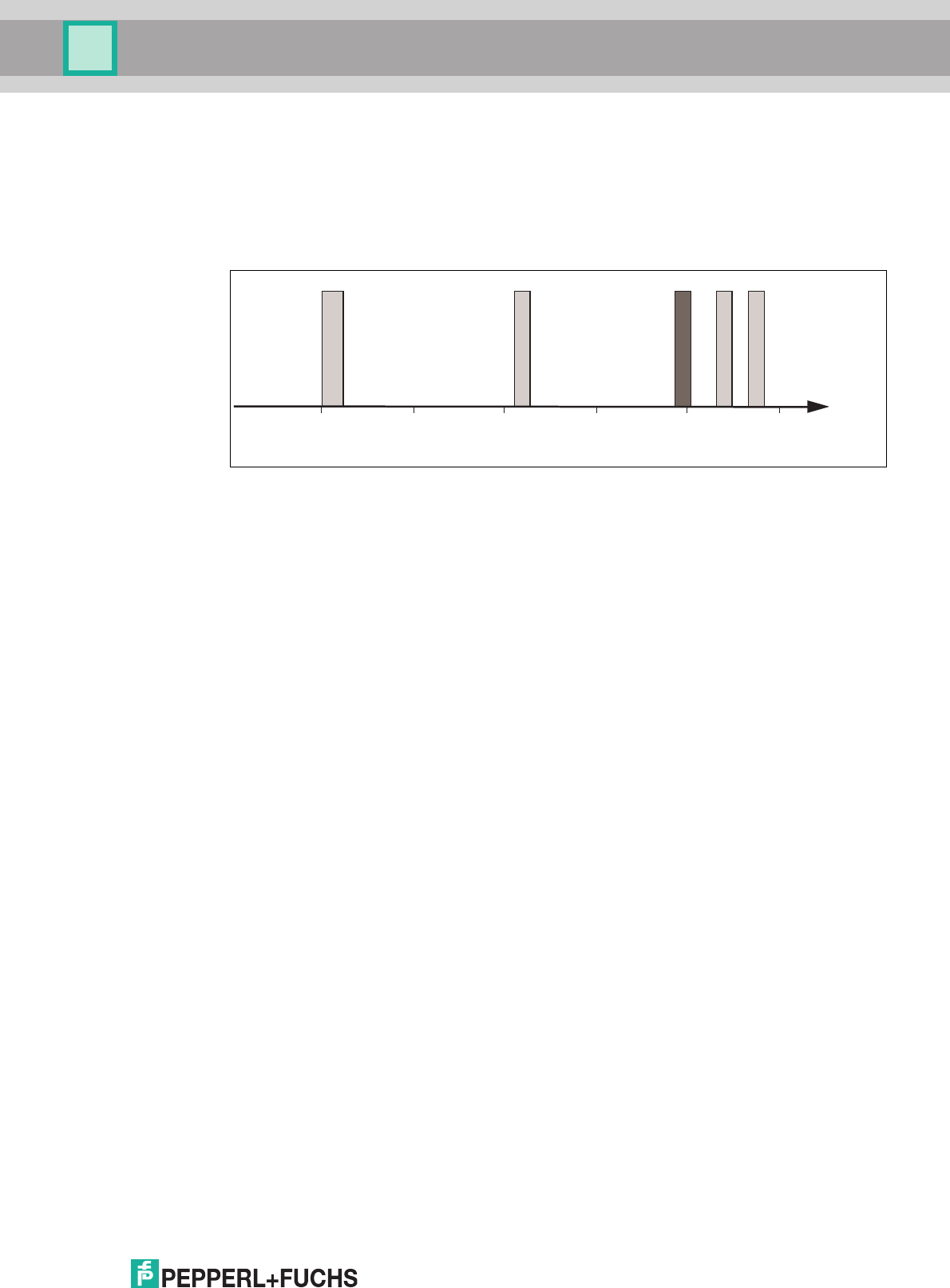
The following diagram shows the position of the different frequency bands used for RFID. The
read/write heads described in this manual operate in the frequency range from 865 MHz ...
868 MHz and from 902 MHz ... 928 MHz, highlighted in color.
■
100 kHz ... 135 kHz: Low frequency LF
■
13.56 MHz: High frequency HF
■
865 MHz ... 868 MHz (Europe), 902 MHz ... 928 MHz (USA), 920 MHz ... 925 MHz
(China): ultra-high frequency UHF
■
2.45 GHz and 5.8 GHz: Microwave MW
3.2 UHF general
3.2.1 Advantages of UHF
■
Long detection range
■
UHF tags are available as cheap and space-saving adhesive labels
■
High transfer rates
■
Tag is available with a large working memory (user memory)
■
Bulk detection
3.2.2 Applications for UHF systems
■
Identification in galvanic coating or painting systems used in automotive production,
■
Identification feasible over greater distances than with LF and HF systems,
■
Identification of automotive superstructures in automotive production,
■
Pallet identification and measurement of goods movements in the logistics sector, and
■
Access control at unloading stations with HGV identification.
Frequency
[MhZ]
125 kHz
2,45 GHz
13,56 MHz
5,8 GHz
868/915 MHz
0,1
LF
1 10
HF
100 1000
UHF
10000
MW
2017-12
12
IUH-F190-V1-*, IUT-F190-R4-V1*
Product Description
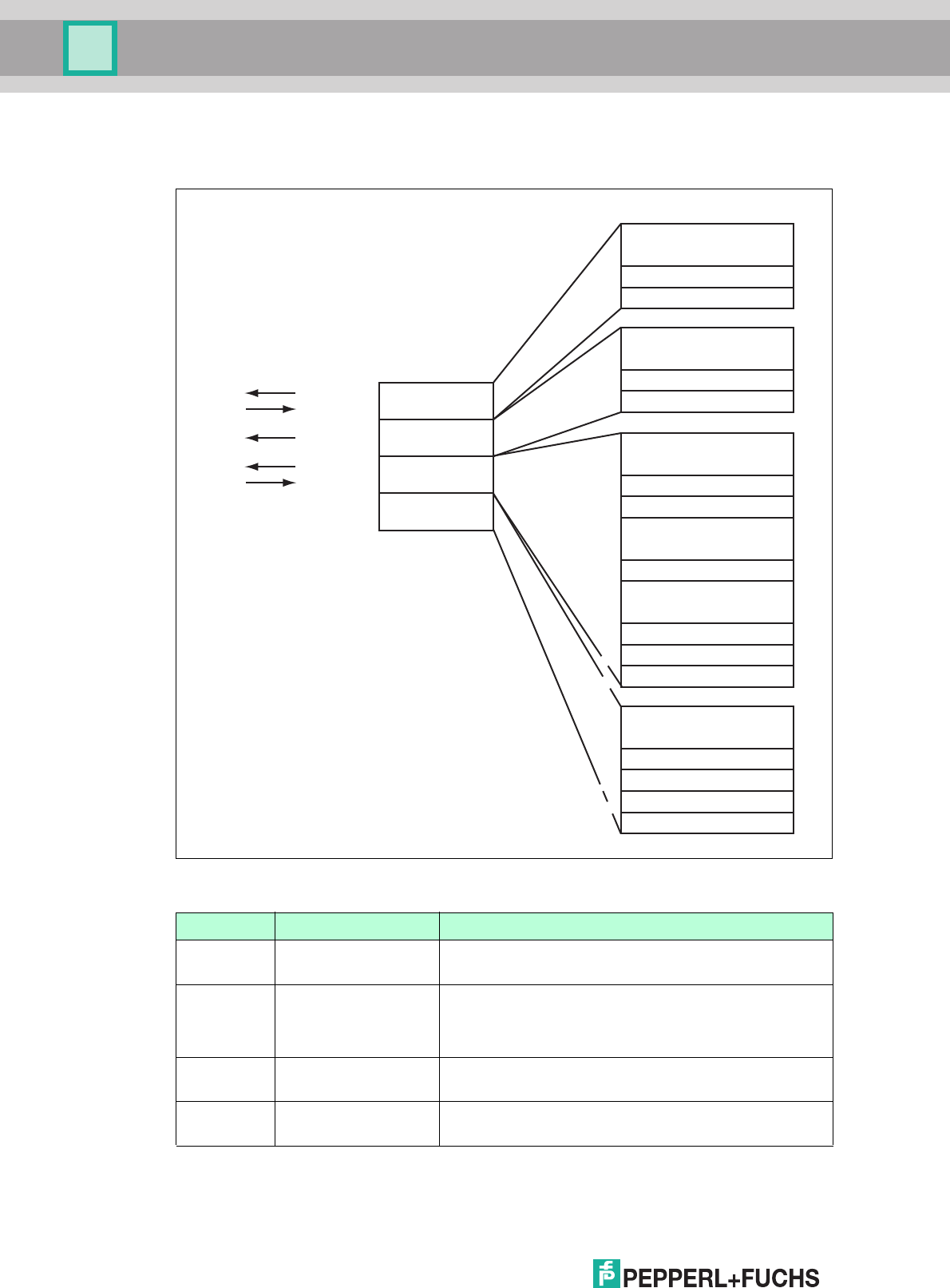
3.2.3 Memory Structure of a Tag in Accordance with EPC Gen 2
(ISO/IEC 18000-63)
The memory module of an EPC Gen 2 (ISO/IEC 18000-63) tag is split into four segments. The
main contents of these segments are:
Segment Function Length
Bank 00
(00
bin
= 0
dec
)
Password
management
Depending on the tag type, /column "Bank 00"
Bank 01
(01
bin
= 1
dec
)
Unique Item Identifier
(UII)
Electronic Product
Code (EPC)
Depending on the tag type, /column "UII/EPC"
Bank 10
(10
bin
= 2
dec
)
Tag ID (TID) 4 bytes (MDID, TMN) + 0, 4, or 8 bytes
Bank 11
(11
bin
= 3
dec
)
User memory Depending on the tag type, /column "User Data"
USER
TID
UII/EPC
RESERVED
RFU [7:0]
10h1Fh
.
.
.
MSB LSB
DSFID [7:0]
00h0Fh
TID [15:0]
10h1Fh
.
.
.
MSB LSB
TID [31:16]
00h0Fh
UII/EPC [N:N-15]
20h
210h
2Fh
.
.
.
MSB LSB
PC [15:0]
10h1Fh
UII/EPC [15:0]
CRC-16 [15:0]
00h0Fh
Access Password [15:0]
30h3Fh
.
.
.
MSB LSB
Access Password [31:16]
20h2Fh
Kill Password [15:0]
10h1Fh
Kill Password [31:16]
00h0Fh
Bank 11
Bank 10
Bank 01
Bank 00
SR/ER
SW/EW
SS/ES
SP
SF/EF
.
.
.
Optional XPC_W2 [15:0]
Optional XPC_W2 [15:0]
.
.
.
220h
21Fh
22Fh
Memory module
Commands
Read / write head

IUH-F190-V1-*, IUT-F190-R4-V1*
Product Description
2017-12
13
Bank 00: Password Management
The segment Bank 00 contains the password management information, comprising the
access password and the kill password. The read/write head manages the kill password with
the standard read/write commands SW and SR. The access password is not supported. See
"Single Read Words SR" on page 42, see "Single Write Words SW" on page 42, and see
"Memory Module for Tag Accesses to the "Memory Bank" MB" on page 52.
Bank 01: UII/EPC
In addition to the Unique Item Identifier (UII), the segment Bank 01 contains a calculated
checksum CRC (Cyclic Redundancy Check) for verifying data on the tag and the protocol
control (PC) area. The PC area contains:
■
The length of the UII
■
The Application Family Identifier (AFI) box
■
A bit switch that shows whether the UII contains an EPC sequence of numbers in
accordance with ISO (see chapter 3.2.4)
■
A bit switch that shows whether data is stored in segment bank 11 (if present)
The data is addressed via the following commands: single read special read-only code (SS),
single write special read-only code (SP), and enhanced read special read-only code (ES). See
"Single Read Special Read-Only Code SS" on page 40, see "Single Write Special Read-Only
Code SP" on page 41, and see "Enhanced Read Special Read-Only Code ES" on page 40.
Bank 10: TID
The segment Bank 10 contains the tag identifier (TID), consisting of the part number and
optional serial number of the tag. This data is permanently stored without being changed. The
first byte denotes the class of the tag with E0
hex
, E2
hex
, or E3
hex
. The rest of the TID depends
on the class, and can be derived from standard ISO/IEC 18000-63.
Example:
All tags with the class EPC Gen 2 (ISO/IEC 18000-63) are marked with E2
hex
. The TID is
comprised as follows:
■
4 bytes: part number of the tag
• 1 byte: identifier
• 12 bits: tag mask designer identifier (MDID)
• 12 bits: tag model number (TMN), defined by the manufacturer:
■
4 or 8 bytes: serial number of the tag
Depending on the manufacturer, the serial numbers do not have to be unique or may even
be omitted.
The data in segment Bank 10 can be output via the single read read-only code (SF) and
enhanced read read-only code (EF) commands. (see "Single Read Read-Only Code SF" on
page 39 and see "Enhanced Read Read-Only Code EF" on page 39)
Bank 11: User Memory
Segment Bank 11 contains an area to which the user has free access. This size of this area
depends on the chip type, or the area may not be present.
The data in segment Bank 11 is addressed via the single read words (SR), single write words
(SW), enhanced read words (ER), and enhanced write words (EW) commands. (see "Single
Read Words SR" on page 42, see "Single Write Words SW" on page 42, see "Enhanced Read
Words ER" on page 42, and see "Enhanced Write Words EW" on page 43)
2017-12
14
IUH-F190-V1-*, IUT-F190-R4-V1*
Product Description
3.2.4 Electronic Product Code (EPC)
The electronic product code is a unique identifier in the form of a sequence of numbers. The
number sequence has a set structure and a length of 64 bits, 80 bits, 96 bits, or longer
(depending on the EPC Ident number used). This number sequence is saved to the RFID tag,
offering worldwide unique identification of the tagged object.
The system of Electronic Product Codes (EPC) was defined by GS1/EPCglobal for use in
inventory management. Tags with memory banks for EPC codes must be programmed by the
user. The memory of new tags must not contain any valid EPC codes. The EPC numbers are
managed and assigned by GS1. To obtain EPC numbers, please contact the GS1 branch in
your country (http://www.gs1.com/contact).
The electronic product code is defined by EPCglobal with at present 13 different encoding
schemes. SGTIN-96 (serialized global trade item number) is given here as an example of a
frequently used encoding scheme. SGTIN-96 has a defined format, and is structured as
follows:
1. Header: The header specifies the EPC standard used, and denotes the number se-
quence.
2. Filter value: Denotes the unit of the product, for example, end product, additional pack-
aging, pallet.
3. Partition: Denotes the point at which the following company prefix ends and the object
data begins.
4. Company Prefix: Assigned sequence of numbers that identifies the producer.
5. Object class: Sequence of numbers that describes the object, e.g., item number.
The company prefix and the object class are each of variable length, but together are al-
ways 44 bits long.
6. Serial number: Sequence of numbers that identifies the item, e.g., the sequential serial
number of the item.
3.2.5 Influence of various materials on the sensing range
In the UHF range, the nature of the surrounding area and the surface to which the transponder
is secured have a serious influence on the range that the system can attain. The UHF
transponder cannot be mounted on metal without requiring adaptations. Glass has a negative
influence on the sensing range when used as a mounting surface. If a UHF transponder is
mounted on damp material, the sensing range is much poorer than the range of a transponder
mounted on dry material. The mounting surface often affects the read range much more than
the material between the transponder and the read/write head. The graph shows the effect of
different materials on the sensing range.
8 Bit 3 Bit 3 Bit 20 - 40 Bit 4 - 24 Bit 38 Bit
5dez
0dez
48dez 4050143 dez 203886dez
124 dez
Header
Filter value
Partition
Company Prefix
Object class Serial number
Length
Value
IUH-F190-V1-*, IUT-F190-R4-V1*
Product Description
2017-12
15
3.2.6 Dense Reader Mode (DRM)
Europe
A special operating mode for read/write tags in accordance with the specification EPC Gen 2
(ISO/IEC 18000-63) allows several read/write heads to be operated close to each other
simultaneously without interference.
In accordance with EN 302208, the read/write head uses only channels 4, 7, 10, and 13 in this
mode for transmission (read/write head read/write tag communication path). The
transmission power is a maximum of 2 W
ERP
in accordance with EN 302208.
Figure 3.1
The response from the read/write tag appears via the frequency offset, which is achieved by
the modulation used in this mode on the two adjacent channels. Due to the high level
difference between the transmission channels and the response channels, this technology
offers major benefits for reusing frequencies.
0 %
10 %
20 %
30 %
40 %
50 %
60 %
70 %
80 %
90 %
100 %
Material
underground
Material between transponder and
read / write head
Foam material
Film
Cardboard (dry)
Cardboard (wet)
Wood (dry)
Glass
Metal
Ai
r
Fi
l
m
C
ar
d
bo
a
r
d
(
d
r
y
)
C
a
rd
b
oard
(w
et
)
Woo
d
(
d
r
y
)
F
oam
m
a
t
e
r
i
a
l
G
la
s
s
M
e
t
a
l
Werp
2.0
865.0 868.0865.7 867.5 MHz
1 2 3 4 5 6 7 8 9 10 11 12 13 14 15 Channel
866.9866.3
2017-12
16
IUH-F190-V1-*, IUT-F190-R4-V1*
Product Description
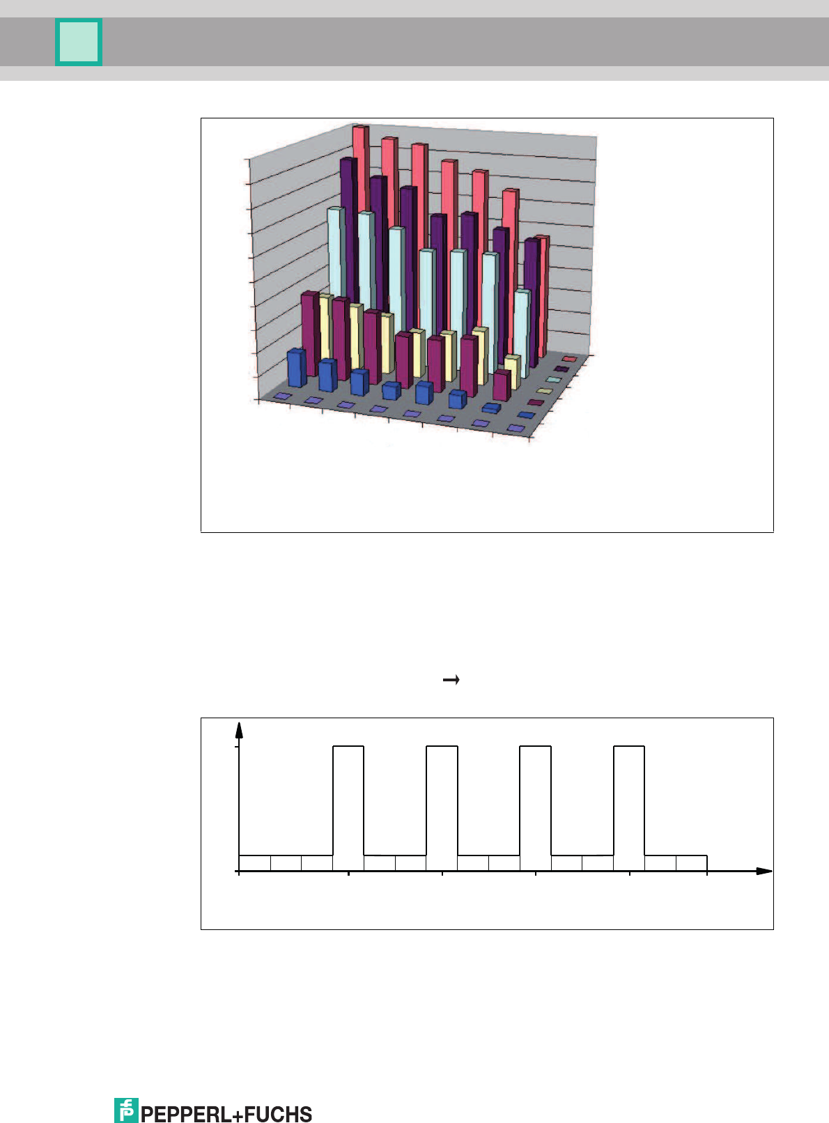
3.2.7 Frequency Hopping Spread Spectrum
With FHSS (Frequency Hopping Spread Spectrum), the information to be transmitted is
distributed successively through multiple channels. Only one frequency channel is used at any
one time. This results in a larger bandwidth for the entire signal, in spite of the fact that each
channel has a smaller bandwidth. In this section the channel assignment for China and the
USA is shown graphically. For both assignments, different parameters apply, such as channel
number and channel bandwidth. Different parameterizations apply in other countries.
China
In China, the frequency range 920 MHz ... 925 MHz is available for UHF-RFID read/write
heads. The range is split into channels, each with a bandwidth of 250 kHz. A maximum of 2
W
ERP
is permitted on 16 of the available channels. The transmission power is indicated in
W
ERP
. FHSS is used with a maximum retention time of two seconds. The UHF RFID read/write
head for China uses channel 2 to 17.
Figure 3.2
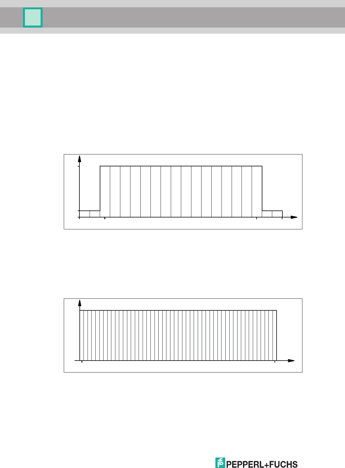
United States
The ISM band from 902 MHz ... 928 MHz is available in the USA. The band is split into 50
channels, each with a 500 kHz bandwidth. FHSS with a maximum retention time of 0.4
seconds is used. All channels must be used. Channel restriction is not permitted.
In contrast to the read/write heads for Europe and China, the transmission power is indicated in
W
eirp
. A maximum of 4 W
eirp
is permitted on all channels.
Figure 3.3
Channel
0.1
2.0
920 925920.625 924.375 MHz
Werp
0 1 2 3 4 5 6 7 8 9 10 11 12 13 14 15 16 17 18 19
0.2
4.0
902.75 927.25MHz
Channel
Weirp
10 15 2051 30 35 4025 45 50

IUH-F190-V1-*, IUT-F190-R4-V1*
Product Description
2017-12
17
3.2.8 Relevant Standards for UHF
European radio standards: EN 300220 and EN 302208
Usage recommendations for RFID type labels, information about recycling, installation of
readers and antennae: ISO/IEC TR 24729 parts 1-4
Installation and commissioning of UHF-RFID systems: ETSI TR 102436
Description of air interface: EPC Gen 2 (ISO/IEC 18000-63)
3.3 Countries of Use
The frequency access procedure used is part of the country-specific settings.
Frequency Access Method
■
In many countries, including the USA and China, a frequency hopping spread spectrum is
used. See chapter 3.2.7. The number and position of the frequencies is fixed and cannot
be changed by the user. All channels are used.
■
A programmable frequency list is used in other countries, including the European Union,
Singapore, Vietnam, and India. You can compile this frequency list from a specified set of
channels. Four channels are specified in the European Union as appropriate for dense
reader mode in accordance with EN 302208. See chapter 3.2.6. With this setting, you can
configure one, multiple, or all four channels.
3.3.1 European Union
In the European Union, the use of RFID in the UHF range is regulated by EN 302208.
■
UHF wavelength: 865 MHz 868 MHz
■
Radiated power: 3 mW 1000 W
ERP
; Default = 50 mW
ERP
■
Channel bandwidth: 200 kHz
■
Channel spacing: 600 kHz
■
Frequency access method: programmable frequency list
■
Number of predefined channels: 4
Programmable channels: 4, 7, 10, 13
Center frequencies: 865.7 MHz, 866.3 MHz, 866.9 MHz, 867.5 MHz
Up to 4 channels can be parameterized and used in sequence.
Default: dense reader mode with channel 4, 10, 7, 13. See chapter 3.2.6.
Note!
Transmission License
A country-specific transmission license is required to operate the read/write head. In the
European Union, the manufacturer's declaration of conformity constitutes an adequate license.
All currently valid transmission licenses can be found in the datasheet for the respective
read/write head at www.pepperl-fuchs.com.
Note!
Country Identifier
All read/write heads operate within their maximum frequency range with the appropriate
settings for the relevant country. The country-specific settings are configured during production
and cannot be subsequently modified.
Note!
If you wish to use the read/write head in a country not included in this chapter, make sure the
relevant values for the read/write head are consistent with the local conditions before use.

2017-12
18
IUH-F190-V1-*, IUT-F190-R4-V1*
Product Description
3.3.2 Argentina
The regulations for the UHF frequency range in Argentina are the same as the regulations for
the UHF frequency range in the USA. See chapter 3.3.18.
3.3.3 Australia
In Australia, the use of RFID in the UHF range is regulated as follows:
■
UHF wavelength: 920 MHz ... 926 MHz
■
Radiated Power: 3 1250 mW
EIRP
; Default = 125 mW
EIRP
■
Channel bandwidth: 500 kHz
■
Channel spacing: 500 kHz
■
Frequency access method: frequency hopping spread spectrum. See chapter 3.2.7.
■
Number of channels: 12
Channels used: 1, 2, 3, ... 12
Center frequencies: 919.75 MHz + (M x 0.5) MHz
All 12 channels are always used.
3.3.4 Brazil
In Brazil, the use of RFID in the UHF range is regulated as follows:
■
UHF wavelength: 915 MHz 928 MHz
■
Radiated Power: 3 1250 mW
EIRP
; Default = 125 mW
EIRP
■
Channel bandwidth: 250 kHz
■
Channel spacing: 250 kHz
■
Frequency access method: frequency hopping spread spectrum. See chapter 3.2.7.
■
Number of channels: 52
Channels used: 1, 2, 3, ... 52
Center frequencies: 914.875 MHz + (M x 0.25) MHz
All 52 channels are always used.
3.3.5 Canada
The regulations for the UHF frequency range in Canada meet the requirements for the UHF
frequency range in the U.S.. See chapter 3.3.18.
3.3.6 China
In China, the use of RFID in the UHF range is regulated by the provisions of the China Ministry
of Industry and Information Technology (CMIIT).
■
UHF wavelength: 920 MHz ... 925 MHz
■
Radiated Power: 3 800 mW
ERP
; Default = 80 mW
ERP
■
Channel bandwidth: 250 kHz
■
Channel spacing: 250 kHz
■
Frequency access method: frequency hopping spread spectrum (China). See chapter
3.2.7.

IUH-F190-V1-*, IUT-F190-R4-V1*
Product Description
2017-12
19
■
Number of channels: 16
Channels used: 2, 3, 4, ... 17
Center frequencies: 920.125 MHz + (M x 0.25) MHz
All 16 channels are always used.
3.3.7 Hong Kong
The regulations for the UHF frequency range of 865 MHz to 868 MHz in Hong Kong are the
same as the regulations for the UHF frequency range in the European Union. See chapter
3.3.1.
The regulations for the UHF frequency range of 920 MHz to 925 MHz in Hong Kong are the
same as the regulations for the UHF frequency range in Thailand. See chapter 3.3.17.
3.3.8 India
In India, the use of RFID in the UHF range is regulated in accordance with EN 302208.
■
UHF wavelength: 865 MHz 867 MHz
■
Radiated Power: 3 800 mW
ERP
; Default = 50 mW
ERP
■
Channel bandwidth: 200 kHz
■
Channel spacing: 200 kHz
■
Frequency access method: programmable frequency list
■
Number of predefined channels: 10
Programmable channels: 1, 2, 3, ... 10
Center frequencies: 865.1 MHz, 865.3 MHz, 865.5 MHz, 865.7 MHz, 865.9 MHz,
866.1 MHz, 866.3 MHz, 866.5 MHz, 866.7 MHz, 866.9 MHz
Up to ten channels can be parameterized and used in sequence.
Default: dense reader mode on channel 1, 7, 4, 10. See chapter 3.2.6.
3.3.9 Japan
In Japan, the use of RFID in the UHF range is regulated as follows:
■
UHF wavelength: 916.7 MHz 920.5 MHz
■
Radiated Power: 3 1250 mW
EIRP
; Default = 125 mW
EIRP
■
Channel bandwidth: 200 kHz
■
Channel spacing: 1200 kHz
■
Frequency access method: programmable frequency list.
■
Number of predefined channels: 4
Programmable channels: 5, 11, 17, 23
Center frequencies: 916.8 MHz, 918.0 MHz, 919.2 MHz, 920.4 MHz
Up to four channels can be parameterized and used in sequence.
Default: dense reader mode on channel 5, 17, 11, 23. See chapter 3.2.6.
3.3.10 Colombia
The regulations for the UHF frequency range in Colombia are the same as the regulations for
the UHF frequency range in the USA. See chapter 3.3.18.
3.3.11 Malaysia
In Malaysia, the use of RFID in the UHF range is regulated as follows:

2017-12
20
IUH-F190-V1-*, IUT-F190-R4-V1*
Product Description
■
UHF wavelength: 919 MHz 923 MHz
■
Radiated Power: 3 800 mW
ERP
; Default = 80 mW
ERP
■
Channel bandwidth: 500 kHz
■
Channel spacing: 500 kHz
■
Frequency access method: frequency hopping spread spectrum. See chapter 3.2.7.
■
Number of channels: 8
Channels used: 1, 2, 3, ... 8
Center frequencies: 918.75 MHz + (M x 0.5) MHz
All 8 channels are always used.
3.3.12 Mexico
The regulations for the UHF frequency range in Mexico meet the requirements for the UHF
frequency range in the U.S.. See chapter 3.3.18.
3.3.13 New Zealand
In New Zealand, the use of RFID in the UHF range is regulated as follows:
■
UHF wavelength: 921.5 MHz 928 MHz
■
Radiated Power: 3 1250 mW
EIRP
; Default = 125 mW
EIRP
■
Channel bandwidth: 500 kHz
■
Channel spacing: 500 kHz
■
Frequency access method: frequency hopping spread spectrum. See chapter 3.2.7.
■
Number of channels: 13
Channels used: 1, 2, 3, ... 13
Center frequencies: 921.25 MHz + (M x 0.5) MHz
All 13 channels are always used.
3.3.14 Russia
In Russia, the use of RFID in the UHF range is regulated in accordance with EN 302208:
■
UHF wavelength: 866 MHz 867.6 MHz
■
Radiated Power: 3 800 mW
ERP
; Default = 50 mW
ERP
■
Channel bandwidth: 200 kHz
■
Channel spacing: 200 kHz
■
Frequency access method: programmable frequency list.
■
Number of predefined channels: 8
Programmable channels: 1, 2, 3, ... 8
Center frequencies: 866.1 MHz, 866.3 MHz, 866.5 MHz, 866.7 MHz, 866.9 MHz,
867.1 MHz, 867.3 MHz, 867.5 MHz
Up to eight channels can be parameterized and used in sequence.
Default: dense reader mode on channel 1, 7, 4. See chapter 3.2.6.
3.3.15 Singapore
In Singapore, the use of RFID in the UHF range of 866 MHz to 868 MHz is regulated in
accordance with EN 302208.

IUH-F190-V1-*, IUT-F190-R4-V1*
Product Description
2017-12
21
■
UHF wavelength: 866 MHz 868 MHz
■
Radiated Power: 3 500 mW
ERP
; Default = 50 mW
ERP
■
Channel bandwidth: 200 kHz
■
Channel spacing: 200 kHz
■
Frequency access method: programmable frequency list
■
Number of predefined channels: 10
Programmable channels: 1, 2, 3, ... 10
Center frequencies: 866.1 MHz, 866.3 MHz, 866.5 MHz, 866.7 MHz, 866.9 MHz,
867.1 MHz, 867.3 MHz, 867.5 MHz, 867.7 MHz, 867.9 MHz
Up to ten channels can be parameterized and used in sequence.
Default: dense reader mode on channel 1, 7, 4, 10. See chapter 3.2.6.
In Singapore, the use of RFID in the UHF range of 920 MHz to 925 MHz is regulated as follows.
■
UHF wavelength: 920 MHz ... 925 MHz
■
Radiated Power: 3 800 mW
ERP
; Default = 80 mW
ERP
■
Channel bandwidth: 500 kHz
■
Channel spacing: 500 kHz
■
Frequency access method: frequency hopping spread spectrum. See chapter 3.2.7.
■
Number of channels: 10
Channels used: 1, 2, 3, ... 10
Center frequencies: 919.75 MHz + (M x 0.5) MHz
All 10 channels are always used.
3.3.16 South Korea
In South Korea, the use of RFID in the UHF range is regulated as follows:
■
UHF wavelength: 917.2 MHz 920.4 MHz
■
Radiated Power: 3 1250 mW
EIRP
; Default = 125 mW
EIRP
■
Channel bandwidth: 200 kHz
■
Channel spacing: 600 kHz
■
Frequency access method: frequency hopping spread spectrum. See chapter 3.2.7.
■
Number of channels: 6
Channels used: 1, 4, 7, 10, 13, 16
Center frequencies: 917.1 MHz + (M x 0.20) MHz
All 6 channels are always used.
3.3.17 Thailand
In Thailand, the use of RFID in the UHF range is regulated as follows:
■
UHF wavelength: 920 MHz ... 925 MHz
■
Radiated Power: 3 1250 mW
EIRP
; Default = 125 mW
EIRP
■
Channel bandwidth: 500 kHz
■
Channel spacing: 500 kHz
■
Frequency access method: frequency hopping spread spectrum. See chapter 3.2.7.

2017-12
22
IUH-F190-V1-*, IUT-F190-R4-V1*
Product Description
■
Number of channels: 10
Channels used: 1, 2, 3, ... 10
Center frequencies: 919.75 MHz + (M x 0.5) MHz
All 10 channels are always used.
3.3.18 United States of America
In the USA, the use of RFID in the UHF range is regulated in accordance with the provisions set
out by the Federal Communications Commission (FCC).
■
UHF wavelength: 902 MHz 928 MHz
■
Radiated Power: 31250 mW
EIRP
; Default = 125 mW
EIRP
■
Channel bandwidth: 500 kHz
■
Channel spacing: 500 kHz
■
Frequency access method: frequency hopping spread spectrum (USA). See chapter
3.2.7.
■
Number of channels: 50
Channels used: 1, 2, 3, ... 50
Center frequencies: 902.25 MHz + (M x 0.5) MHz
All 50 channels are always used.
3.3.19 Vietnam
In Vietnam, the use of RFID in the UHF range of 866 MHz to 868 MHz is regulated in
accordance with EN 302208.
■
UHF wavelength: 866 MHz 868 MHz
■
Radiated Power: 3 500 mW
ERP
; Default = 50 mW
ERP
■
Channel bandwidth: 200 kHz
■
Channel spacing: 200 kHz
■
Frequency access method: programmable frequency list
■
Number of predefined channels: 10
Programmable channels: 1, 2, 3, ... 10
Center frequencies: 866.1 MHz, 866.3 MHz, 866.5 MHz, 866.7 MHz, 866.9 MHz,
867.1 MHz, 867.3 MHz, 867.5 MHz, 867.7 MHz, 867.9 MHz
Up to ten channels can be parameterized and used in sequence.
Default: dense reader mode on channel 1, 7, 4, 10. See chapter 3.2.6.
The regulations for the UHF frequency range of 920 MHz to 925 MHz in Vietnam are the same
as the regulations for the UHF frequency range in Singapore. See chapter 3.3.15.
IUH-F190-V1-*, IUT-F190-R4-V1*
Product Description
2017-12
23
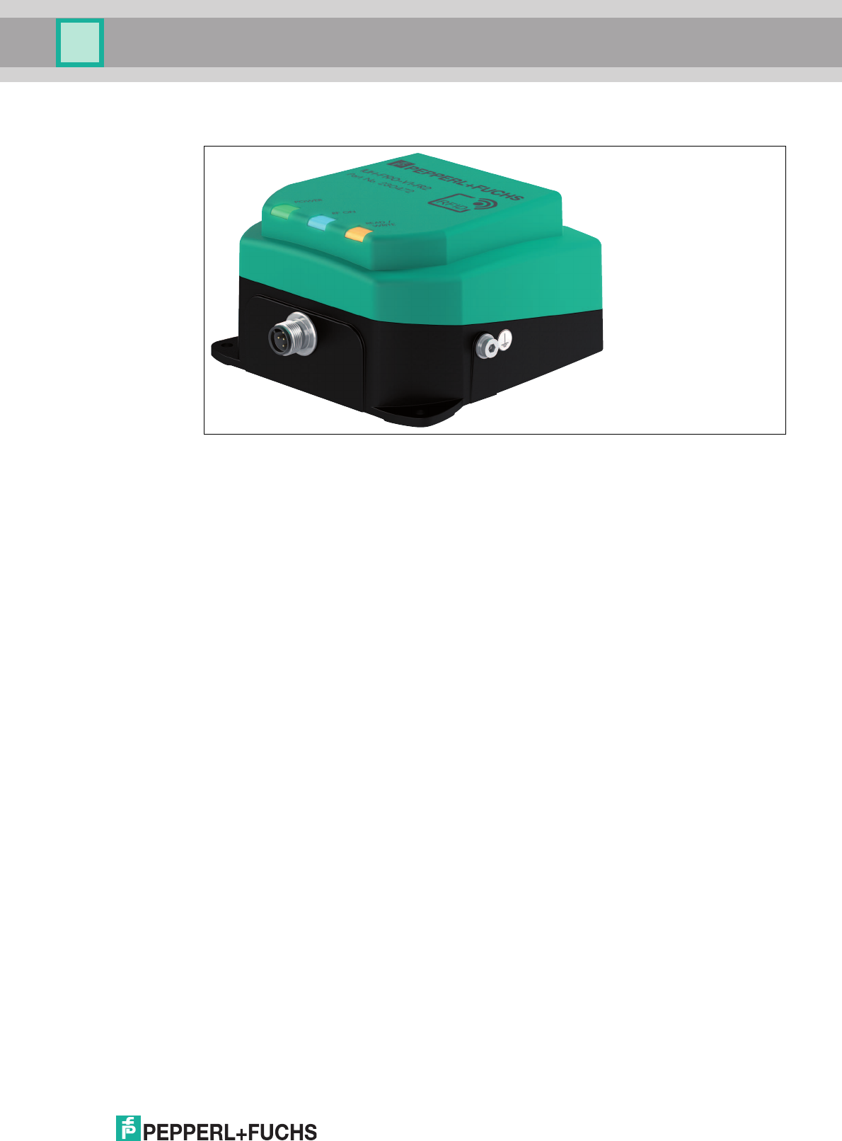
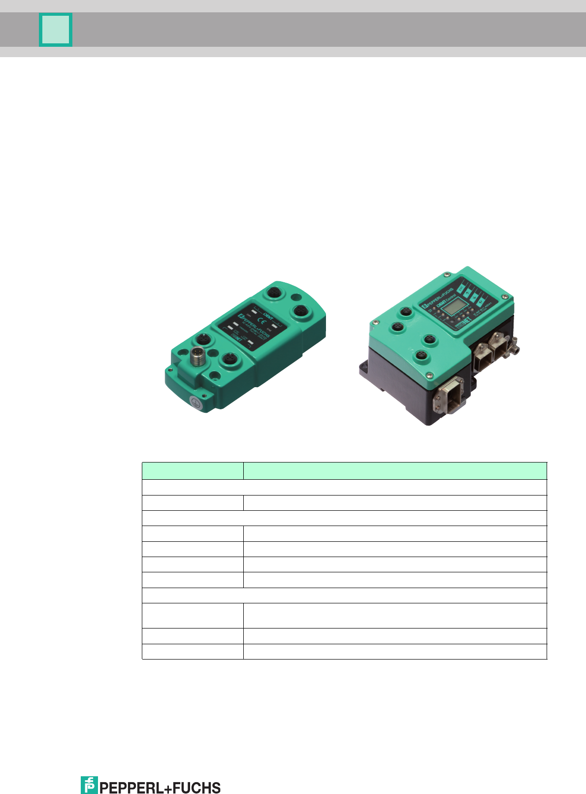
3.4 General Functions and Features
Figure 3.4
Functions
The read/write heads were developed for reading and writing passive read/write tags with a
UHF range operating frequency.
Read/write head IUH-F190-V1-* can only be used together with an IDENTControl control
interface from Pepperl+Fuchs.
Read/write heads IUT-F190-R4-V1-* do not require a control interface and can be connected
by means of a point-to-point connection to a RS-485 serial interface.
Detection range
The detection range is typically 2 meters. Tags that comply with EPC Gen 2 (ISO/IEC 18000-
63) are supported.
Maximum Frequency Range
Read/write heads IUH-F190-V1-FR1* and IUT-F190-R4-V1-FR1* can be operated in the
frequency range from 865 MHz to 868 MHz. Read/write heads IUH-F190-V1-FR2* and IUT-
F190-R4-V1-FR2* can be operated in the frequency range from 902 MHz to 928 MHz.
Features
The read/write head has the following features:
■
3 function indicator LEDs
■
Industrial housing with a compact design
■
Bulk detection
■
Connects to IDENT via connector V1 (M12 x 1)Control
■
Protected against electrostatic discharge
Integrated antenna
The read/write heads have a linear dual polarized antenna. The read/write heads can transmit
and receive waves with horizontal and vertical polarization.
2017-12
24
IUH-F190-V1-*, IUT-F190-R4-V1*
Product Description
3.5 Indicators and Operating Elements
The read/write head has 3 LEDs, which are green/blue/yellow. The various indicators denote:
■
Green LED: Power on
■
Blue LED: Transmission mode
■
Yellow LED: Read/write operation successful
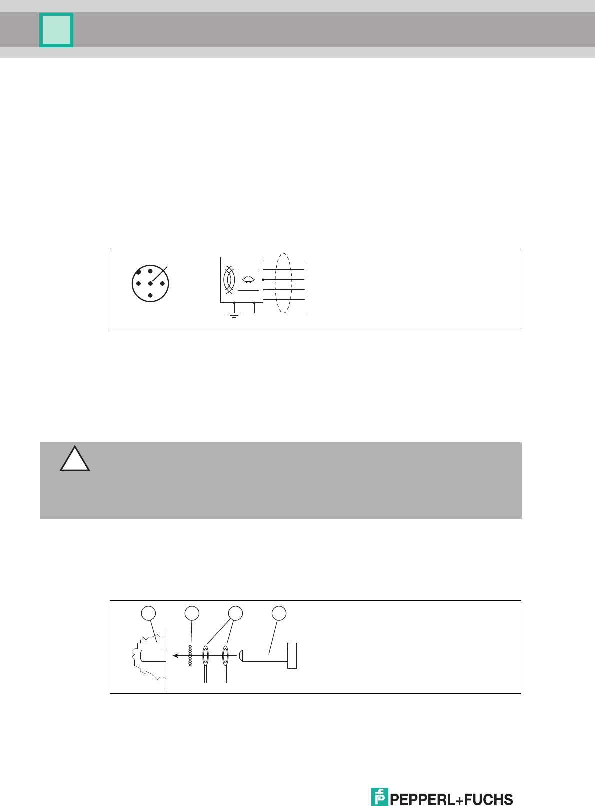
3.6 Connection
IUH-F190-V1-*
The IUH-F190-V1-* read/write head is connected to the IDENTControl control interface via the
M12 x 1 connector.
Figure 3.5
IUT-F190-R4-V1-*
The IUT-F190-R4-V1-* read/write head is connected to an RS-485 serial interface of the parent
device via the M12 x 1 connector via a point-to-point connection. The read/write head has an
internal terminator on the RS-485 interface. For this reason, only one read/write head is
provided within an RS-485 network. It is not possible to build an RS-485 network with multiple
read/write heads. The factory-set transfer rate of the interface is 38,400 bit/s.
Ground connection
The ground connection of the read/write head is positioned on the right-hand side when
viewed from the front, if the cable outlet is facing downward. The ground conductor is screwed
to the housing with a crimp connector. In order to guarantee safe grounding, mount the
serrated washer between the crimp connectors and the housing.
Shield
do not connect
+
A
-
B
1
2
3
5
4
1
4
5
2
3
Caution!
Power Supply
The IUT-F190-R4-V1-* read/write head must only be connected to a current source with limited
power according to EN 60950.
The connection cable of the IUT F190-R4-V1-* read/write head must be no longer than 3 m.
1Housing
2Serrated lock washer
3Crimp connector
4Lock screw
1 2 43
IUH-F190-V1-*, IUT-F190-R4-V1*
Product Description
2017-12
25
Use a ground conductor lead with a cross-section of at least 4 mm
2
.
Tighten the retaining bolt to a tightening torque of 1.6 Nm ± 0.4 Nm.
3.7 Scope of Delivery
■
Read/write head
■
Quick start guide
3.8 Accessories
3.8.1 IDENTControl
The IUH-F190-V1-* read/write head can be connected to Pepperl+Fuchs IDENTControl control
interfaces.
Interface Designation
4 read/write heads:
Ethernet IC-KP-B17-AIDA1
2 read/write heads:
PROFIBUS IC-KP2-2HB6-V15B
Ethernet IC-KP2-2HB17-2V1D
EtherCAT IC-KP2-2HB21-2V1D
Serial IC-KP2-2HRX-2V1
1 read/write head:
PROFIBUS IC-KP2-1HB6-V15B
IC-KP2-1HB6-2V15B
Ethernet IC-KP2-1HB17-2V1D
Serial IC-KP2-1HRX-2V1
Table 3.1
2017-12
26
IUH-F190-V1-*, IUT-F190-R4-V1*
Product Description
3.8.2 Read/Write Tags
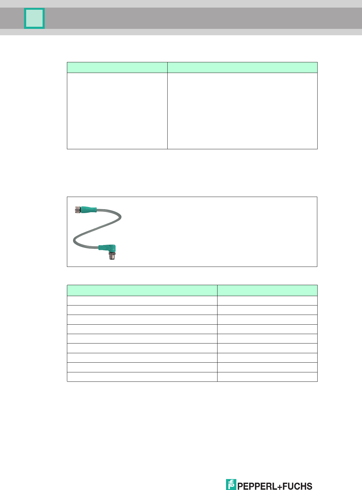
3.8.3 Connection cable for R/W heads and trigger sensors
Compatible connection cables with shielding are available for connecting the R/W heads and
trigger sensors.
Figure 3.6
Type Designation
EPC Gen 2 (ISO/IEC 18000-63) IUC72-F152-M-FR1
IUC72-F152-M-FR2
IUC76-50-FR1
IUC76-50-FR2
IUC76-F157-M-FR1
IUC76-F157-M-FR2
IUC76-F203-M-FR1
IUC76-F203-M-FR2
IUC76-C8-T14-GBL
IUC77-F151-M-GBL
IUC77-25L100-GBL
IUC77-25L110-GBL
Table 3.2
Accessories Description
2 m long (straight female, angled male) V1-G-2M-PUR-ABG-V1-W
5 m long (straight female, angled male) V1-G-5M-PUR-ABG-V1-W
10 m long (straight female, angled male) V1-G-10M-PUR-ABG-V1-W
20 m long (straight female, angled male) V1-G-20M-PUR-ABG-V1-W
Field attachable female connector, straight, shielded V1-G-ABG-PG9
Field attachable male connector, straight, shielded V1S-G-ABG-PG9
Field attachable female connector, angled, shielded V1-W-ABG-PG9
Field attachable male connector, angled, shielded V1S-W-ABG-PG9
Dummy plug M12x1 VAZ-V1-B3
IUH-F190-V1-*, IUT-F190-R4-V1*
Product Description
2017-12
27
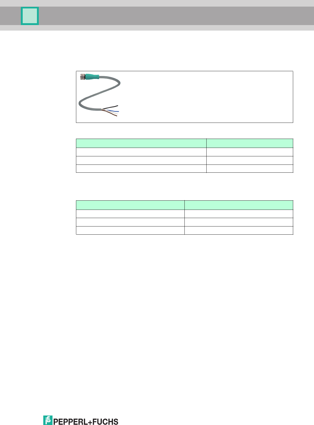
3.8.4 Cable connectors for the power supply
Compatible M12 sockets with an open cable end for connecting the IDENTControl to a power
supply are available in different lengths.
Figure 3.7
3.8.5 Mounting set
Multiple mounting brackets are available to mount the read/write head on the wall or on a pipe.
Accessories Designation
Length 2 m (straight socket) V1-G-2M-PUR
Length 5 m (straight socket) V1-G-5M-PUR
Length 10 m (straight socket) V1-G-10M-PUR
Accessories Designation
Mounting bracket for wall and pipe mounting IUZ-MH12
Mounting bracket for wall mounting IUZ-MH13
Mounting bracket for pipe mounting IUZ-MH15
2017-12
28
IUH-F190-V1-*, IUT-F190-R4-V1*
Installation
4 Installation
4.1 Storage and transport
For storage and transport purposes, package the unit using shockproof packaging material
and protect it against moisture. The best method of protection is to package the unit using the
original packaging. Furthermore, ensure that the ambient conditions are within allowable range.
4.2 Unpacking
Check the product for damage while unpacking. In the event of damage to the product, inform
the post office or parcel service and notify the supplier.
Check the package contents against your purchase order and the shipping documents for:
■
Delivery quantity
■
Device type and version in accordance with the type label
■
Any accessories ordered
Retain the original packaging in case you have to store or ship the device again at a later date.
Should you have any questions, please contact Pepperl+Fuchs.
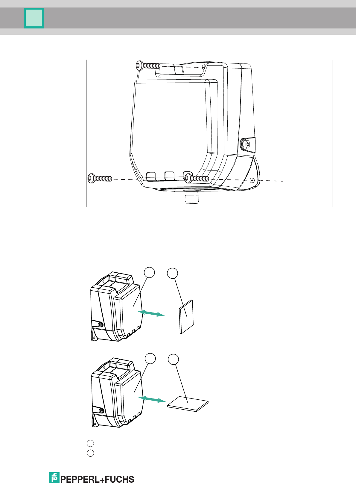
4.3 Mounting
The read/write head is intended for wall mounting or mounting on brackets in internal areas.
Please mount the read/write head using only the holes provided in the housing. The preferred
mounting direction is with the cable connection facing vertically downwards.
To attach the read/write head, use 3 screws with a diameter of 4 mm, as well as mounting
materials that are suitable for the type of mounting surface. The tightening torque of the screws
depends on the type of mounting.
Warning!
Malfunctions with pacemakers
This device does not exceed the permissible limits for electromagnetic fields. Maintain a
minimum distance of 25 cm between the device and your pacemaker.
Inadequate distance from the read/write head can result in inhibitions, reprogramming, or
incorrect stimulation pulses.
Warning!
Hot surfaces
Be careful not to burn your fingers when handling the device! After shutting down the device,
wait at least half an hour before handling the device.
Note!
Do not route the connection cable in the detection range of the antenna.
Caution!
Mounting the read/write head
Make sure that the read/write head is firmly attached to the mounting surface.
Note!
The installation recommendations made in this document are based on favorable conditions.
Pepperl+Fuchs GmbH provides no guarantee of correct function in cross environments.
IUH-F190-V1-*, IUT-F190-R4-V1*
Installation
2017-12
29
Figure 4.1
4.3.1 Room Orientation
The alignment of the read/write tag antennae in relation to the antennae of the read/write head
influences the detection range of the system. Make sure the antennae are aligned parallel to
each other.
Mounting the read/write head
Optimum alignment of the tag
■
Good communication between the
read/write head and tag
Poor alignment of the tag
■
Insufficient communication between the
read/write head and tag
Read/write head
Tag
12
12
1
2
2017-12
30
IUH-F190-V1-*, IUT-F190-R4-V1*
Installation
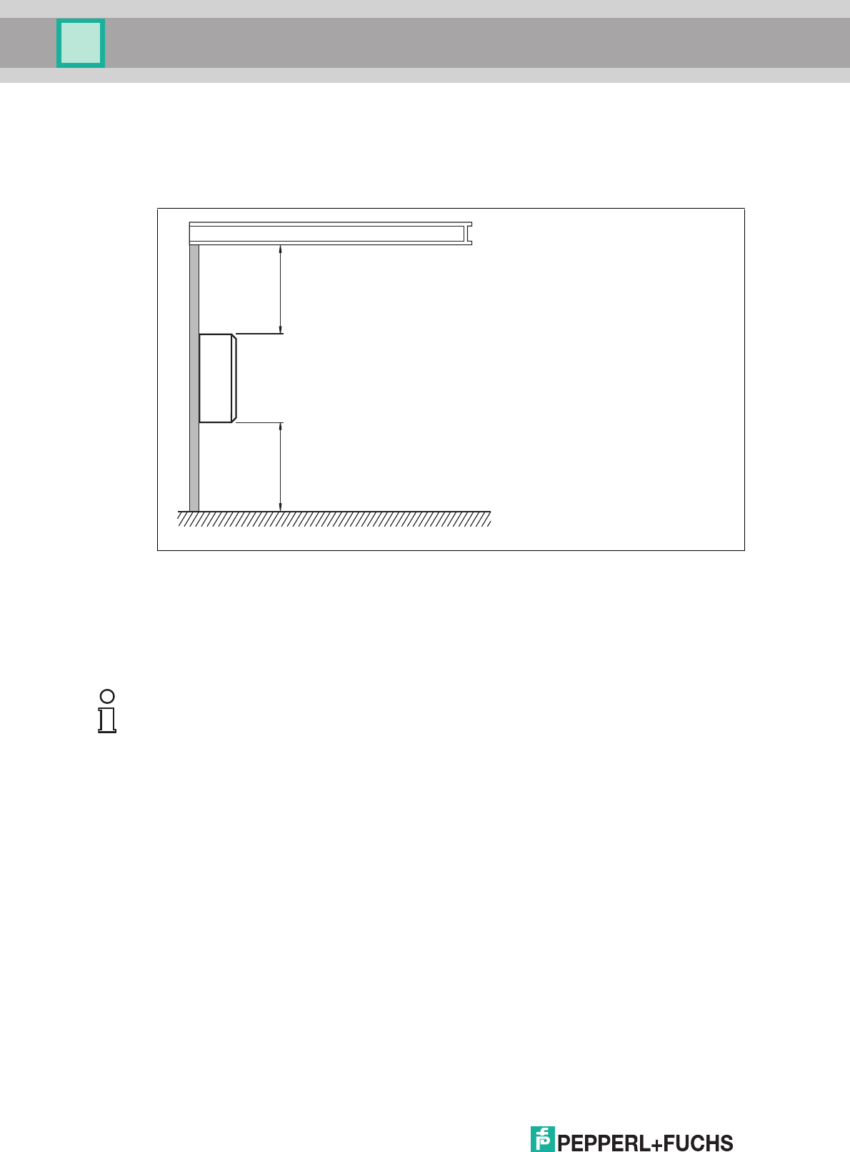
4.3.2 Minimum Distances
When positioning the read/write head, please observe the minimum distances. The lateral
distance between the read/write head and metals or liquids should be at least 50 cm. The
distance between the read/write head and the ground should be at least 50 cm.
Figure 4.2
During simultaneous operation of several read/write heads, only one read/write head may ever
communicate with a tag at any given time. When arranging the read/write heads, make sure
that the measurement ranges do not overlap. You can enlarge or reduce the size of the
measurement range by changing the transmitting power. Determine the measurement range of
each read/write head at the mounting location.
If you want to transmit with just one read/write head at any given time, use the multiplex mode
of the IDENTControl control interface. Multiplex operating mode allows chronologically
exclusive access to tags, and prevents mutual interference from read/write heads. For a precise
description, see the manual for your control interface.
4.3.3 Polarization
The polarization of the electromagnetic wave emitted by an antenna depends on the type of
antenna and is defined for the electromagnetic field component of the electromagnetic wave.
Polarization can be either linear or circular. In the case of an electromagnetic wave with linear
polarization, the direction of the vector of the electromagnetic field component is spatially
constant and therefore dependent on the position of the antenna. Linear polarization can be
either vertical or horizontal.
To achieve the maximum detection range for a UHF system, the polarization of the read/write
head must match the polarization of the tag so that both have the same spatial orientation.
Refer to the relevant data sheet to find the polarization of the tag.
metal support
Read / write
head
min. 50 cmmin. 50 cm
Note!
During mounting, take into account how the read/write heads may cause interference with each
other. The further the transmission channels of the read/write heads are from each other, the
lower the risk of interference.
IUH-F190-V1-*, IUT-F190-R4-V1*
Installation
2017-12
31
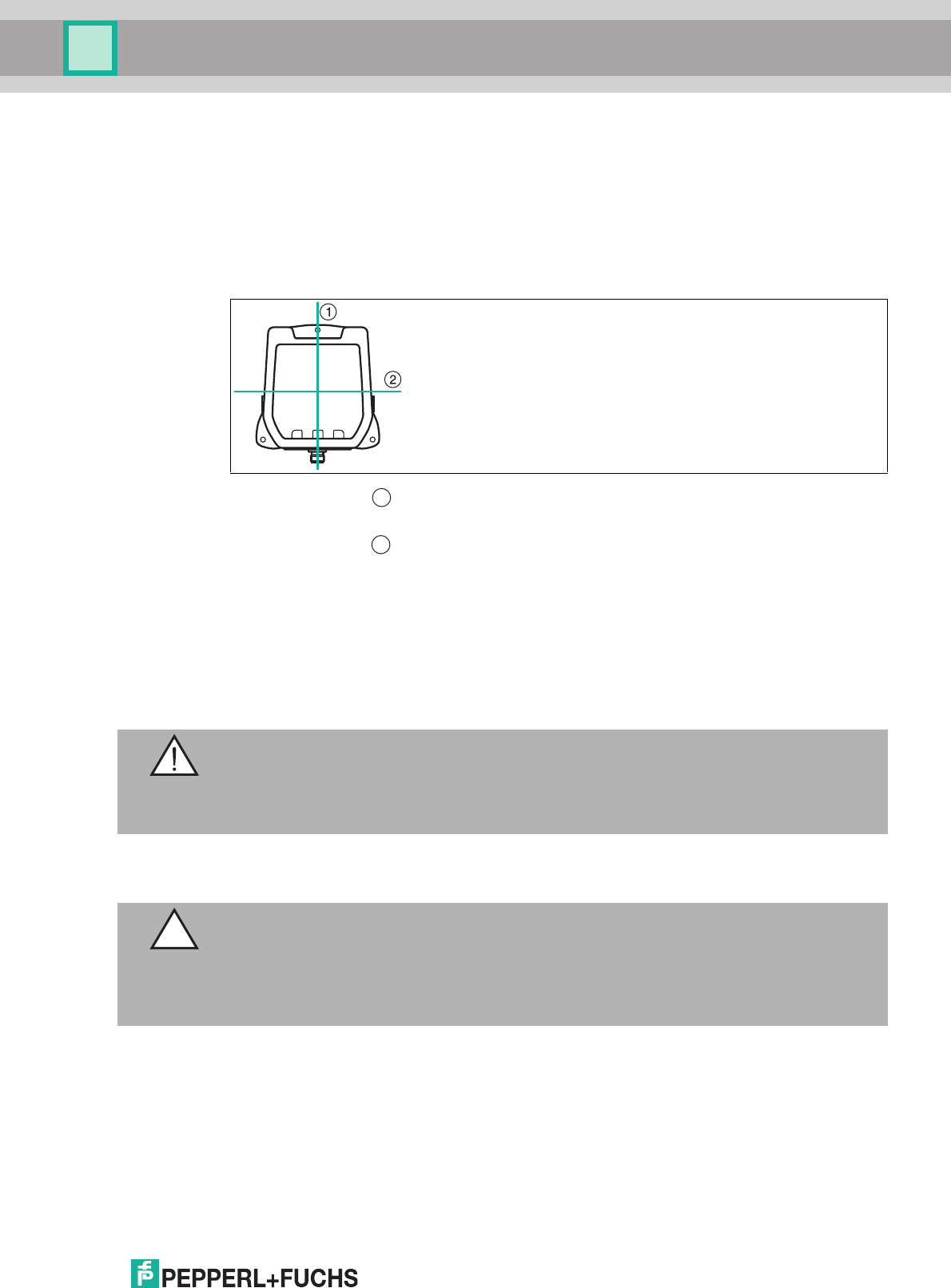
The integrated antenna of the read/write head has dual linear polarization. The read/write head
operates in combined mode by default. In combined mode, both horizontal and vertical
polarization are used for each read/write access. This increases the reading reliability of tags
with an unknown location in the room.
If the orientation of the tags is known, you can optimize the access time by setting a fixed
polarization. To do this, you can switch the polarization to horizontally linear polarization or
vertically linear polarization in the software. The linear polarization plane refers to the preferred
mounting direction with the cable connection mounted vertically downwards.
Figure 4.3 = Vertical polarization plane
= Horizontal polarization plane
4.4 Connection
Connect the IUH-F190-V1-* read/write head to the IDENTControl control interface using a
shielded cordset (see chapter 3.8.3). Ensure that the shield fully encapsulates the connection
cable to avoid EMC interference. (see chapter 4.5)
Connect the IUT-F190-R4-V1-* read/write head to the higher level control unit using a shielded
cordset. Ensure that the shield is fully encapsulating so that interference is dissipated via the
protective earth connections to avoid EMC disturbances.
After connecting the supply voltage, the POWER LED on the device lights up green. If the LED
does not light up on the device, the power supply is not connected correctly.
1
2
Warning!
Incorrect electrical connection
Damage to the device or plant caused by incorrect electrical connection.
Check all connections in the plant before commissioning the device.
Caution!
Power Supply
The IUT F190-R4-V1-* read/write head must only be connected to a current source with limited
power according to EN 60950.
The connection cable of the IUT F190-R4-V1-* read/write head must be no longer than 3 m.
2017-12
32
IUH-F190-V1-*, IUT-F190-R4-V1*
Installation
4.5 EMC Concept
The outstanding noise immunity of the IDENTControl against emission and immission is based
on its consistent shielding design, which uses the principle of the Faraday cage. Interference is
caught in the shield and safely diverted via the ground connections.
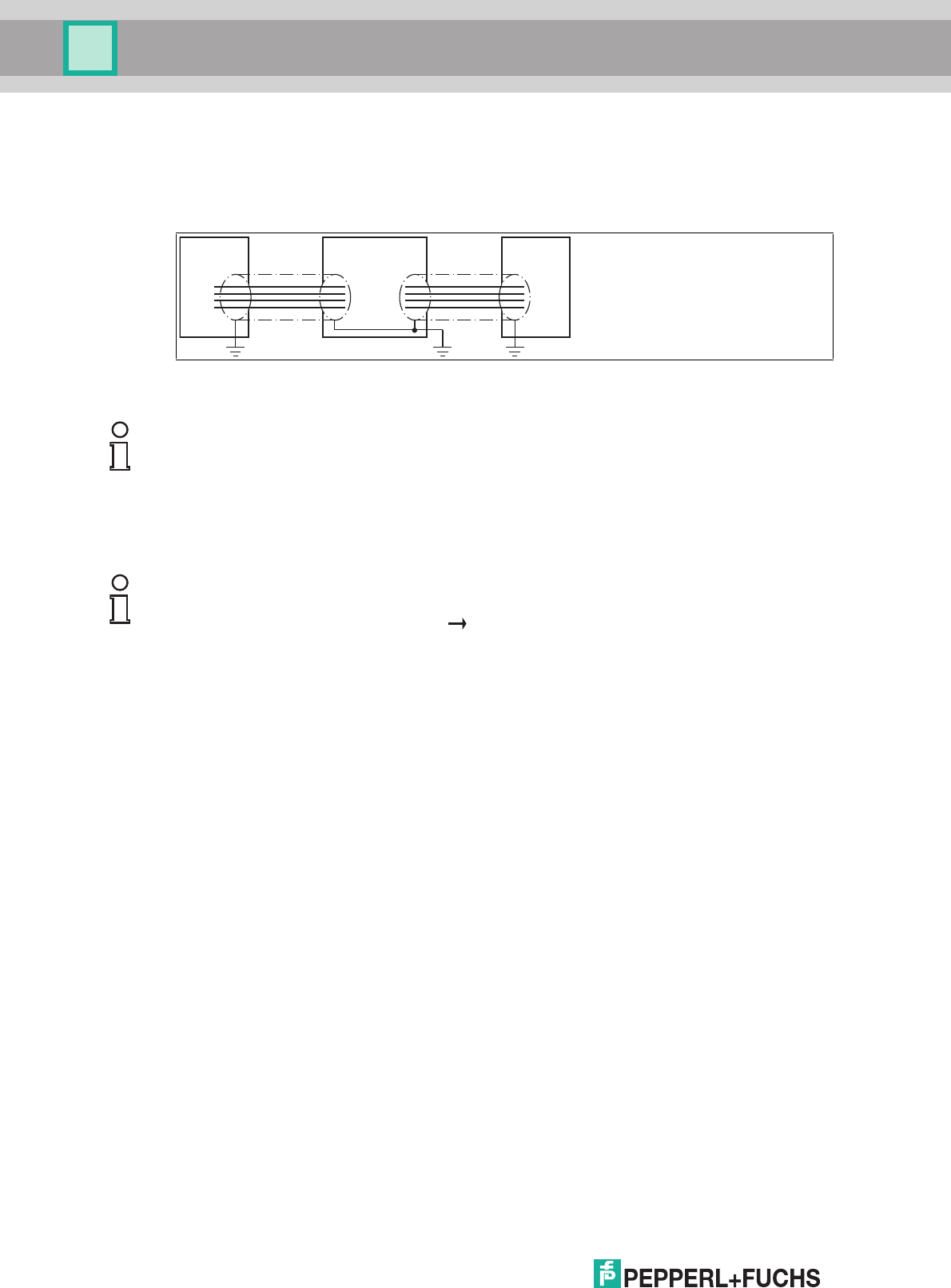
The cable shielding is used to discharge electromagnetic interference. When shielding a cable,
you must connect both sides of the shield to ground with low resistance and low inductance.
write head ControlIDENTControl INTERBUS
Note!
If cables with double shields are used, e.g. wire mesh and metalized foil, the both shields must
be connected together, with low resistance, at the ends when making up the cable.
Power supply cables are the source of much interference, e.g. from the supply lines of 3-phase
electric motors. For this reason, the parallel laying of power supply cables with data and signal
cables should be avoided, particularly in the same cable duct.
Note!
The circuit ground is conductively connected to the housing of the write/read head and to the
protective ground. (Connection image see Figure 3.5 on page 24)

IUH-F190-V1-*, IUT-F190-R4-V1*
Commissioning
2017-12
33
5 Commissioning
5.1 Definitions
5.1.1 Display
Angle brackets contain the abbreviated meaning of a command structure, e.g., <Data>
The index
hex
or .xx denotes a hexadecimal number.
hex
ASCII
denotes a value in the hexadecimal system, specified in ASCII characters.
Example: 10
dec
corresponds to A
hex
; A
ASCII
corresponds to 41
hex
. see chapter 9.2
5.1.2 Legend
<ChanNo>: IDENTControl channel
<CHCK>: 1 byte, 8-bit check sum with the addition of all preceding characters,
without overflow
<Data>: Data with the size <WordNum> multiplied by 4 bytes
<DataLength>: Length of the data specified to a command, 2 characters binary,
HighByte, LowByte
eirp: equivalent isotropically radiated power
erp: effective radiated power
<ETX>: 1 byte = 03
hex
<read-only code>: TID, 4 bytes + an optional 4 or 8 bytes
<Ldata>: Length of the data in bytes, 2 bytes
Use in multiframe protocol
<Length> 1 character hex
ASCII
= number of data bytes
Permitted values in the read/write head IUH*: 2, 4, 6, 8, A, C, E
<Luii>: Length of the UII in bytes, 2 bytes
Use in multiframe protocol
<LogicalOperation>: Links several filters; OR = 0; AND = 1
If one filter only is used, this value is ignored
<MaskData>: Mask specification
<MaskLength>: Mask length in bits, values: 00FF
<MemBank>: Number of the memory bank (see parameter MB)
<ParamTyp>: Parameter type, 2 bytes, or 2 ASCII characters
<Negate>: Negates the mask comparison; not negated = 0; negated = 1
<PC>: Protocol control word according to EPC Gen 2 (ISO/IEC 18000-63), 2
bytes, describes characteristics such as the length of the UI/EPC
<SpecialFixcode>: <PC> & <UII/EPC>
<Status>: 1 ASCII character (see chapter 6.8)
<StartAddress>: Start address in the selected memory bank in bits, values:
0000FFFF
<SystemCode>: = U (for read/write head IUH*)
<TagType>: 2 ASCII characters
<UII/EPC>: Unique Item Identifier, memory area of a tag in accordance with EPC
Gen 2 (ISO/IEC 18000-63), in which the EPC code is stored
2017-12
34
IUH-F190-V1-*, IUT-F190-R4-V1*
Commissioning
5.2 Sensor Settings
You must configure the control interface before commissioning the IUH-F190-V1-* read/write
head. To do so, refer to the "Commissioning" chapter of the manual for your control interface.
Configure the read/write heads with the described system commands (see chapter 6.6.1). For
a parameterization example, see see chapter 5.3.
5.3 Operation via the Command Interface
This section shows you how to commission the IUH-F190-V1-* read/write head using an
IDENTControl control interface with serial interface. The commissioning procedure described
relates to the RS-232 interface and involves a PC. The examples include the syntax for coding
the commands and parameters via the Ethernet TCP/IP and PROFIBUS/PROFINET
interfaces. Further details about these codes and the factory settings for your IDENTControl
control interface can be found in the corresponding manual.
The commissioning of the IUT-F190-R4-V1-* read/write head with integrated RS-485 interface
is also carried out using the above commands and parameters. For details regarding the IUT
F190-R4-V1-* read/write head see chapter 6.7
Example:
In the examples below, the read/write head is connected to channel 1 of the control interface.
The outputs follow the multiframe protocol, see table "Responses Depending on Protocol
Mode QV" on page 56.
Reading Tags
Enhanced Read Read-Only Code
Send the enhanced read read-only code command to the read/write head. The "RF ON" LED
on the read/write head lights up blue.
<WordAddr>: Word start address in the read/write tag, 4 hex
ASCII
characters, range
from "0000h" to "FFFF", depending on tag type
<WordNum>: Number of words to be read or written, 2 hex
ASCII
characters. Range
from "01" through "20" depending on the tag type, word lengths are 4
bytes
Warning!
Device not configured or configured incorrectly
Configure the device prior to commissioning. A device that has not been configured or
configured incorrectly may lead to faults in the plant.
Caution!
Uncontrolled triggered processes
Before commissioning the device, make sure that all processes are running smoothly;
otherwise damage may occur in the plant.
Serial Ethernet PROFIBUS/PROFINET
Command: EF1 .00.04.1D.03 .1D.03
Confirmation: - .00.06.1D.03.FF.0B .1D.03.FF.0B
Response: .35.31 .00.06.1D.03.05.0C .1D.03.05.0C
Table 5.1 Enhanced read read-only code, no tag in the detection range
IUH-F190-V1-*, IUT-F190-R4-V1*
Commissioning
2017-12
35
Move a tag into the read/write head's detection range. When the tag has been detected and the
read-only code has been read out, the "READ / WRITE" LED on the read/write head lights up
yellow. The read-only code is displayed in the terminal program.
Describing Tags
Single Write Special Read-Only Code
Send the single write special read-only code command to the read/write head while a tag is in
the detection range. See "Single Write Special Read-Only Code SP" on page 41 and see
chapter 3.2.4.
Single Read Special Read-Only Code
As confirmation, read out the read-only code of the tag within the read/write head's detection
range via the single read special read-only code command. See "Single Read Special Read-
Only Code SS" on page 40.
Serial Ethernet PROFIBUS/PROFINET
Response: .30.31.00.0E.30.
00.30.14.F7.33.7
C.00.1F.00.00.00
.00.01.00.08.E2.
00.60.03.14.42.D
6.D1
.00.20.1D.03.00.0D.00.0E.
30.00.30.14.F7.33.7C.00.1
F.00.00.00.00.01.00.08.E2
.00.60.03.14.42.D6.D1
.1D.03.00.0D.00.0E.30.00.
30.14.F7.33.7C.00.1F.00.0
0.00.00.01.00.08.E2.00.60
.03.14.42.D6.D1
Table 5.2 Enhanced read read-only code, tag is entering the detection range
Serial Ethernet PROFIBUS/PROFINET
Command: SP1E.30.00.30.1
4.F7.33.7C.00.1F
.00.00.03.1C.6E
.00.14.0D.E3.00.00.30.00.
30.14.F7.33.7C.00.1F.00.0
0.03.1C.6E
.0D.E3.00.00.30.00.30.14.
F7.33.7C.00.1F.00.00.03.1
C.6E
Confirmation: - .00.06.0D.E3.FF.2D .0D.E3.FF.2D
Response: .30.31.00.0E.30.
00.30.14.F7.33.7
C.00.1F.00.00.03
.1C.6E
.46.31.30.30.30.3
1
.00.16.0D.03.00.2E.00.0E.
30.00.30.14.F7.33.7C.00.1
F.00.00.03.1C.6E
.00.0A.0D.03.0F.2F.30.30.
30.31
0D.03.00.2E.00.0E.30.00.
30.14.F7.33.7C.00.1F.00.0
0.03.1C.6E
.0D.03.0F.2F.30.30.30.31
Serial Ethernet PROFIBUS/PROFINET
Command: SS10 .00.04.0A.02 .0A.02
Confirmation: - .00.06.0A.02.FF.30 .0A.02.FF.30
Response: .30.31.00.0E.30.
00.30.14.F7.33.7
C.00.1F.00.00.03
.1C.6E
.46.31.30.30.30.3
1
.00.16.0A.02.00.31.00.0E.
30.00.30.14.F7.33.7C.00.1
F.00.00.03.1C.6E
.00.0A.0A.02.0F.32.30.30.
30.31
.0A.02.00.31.00.0E.30.00.
30.14.F7.33.7C.00.1F.00.0
0.03.1C.6E
.0A.02.0F.32.30.30.30.31
2017-12
36
IUH-F190-V1-*, IUT-F190-R4-V1*
Commissioning
Parameterizing the Read/Write Head
Requesting and Setting the Transmission Power
Read out the read/write head's transmission power with the read parameter PT command:
The read/write head's set transmission power is 50 mW (32
hex
corresponding to 50
dec
).
Change the transmission power of the read/write head to 100 mW (100
dec
corresponding to
64
hex
) via the write parameter PT command:
Serial Ethernet PROFIBUS/PROFINET
Command: RP1UPT.00.00 .00.0A.BE.03.00.55.50.54.
00.00
.BE.03.00.55.50.54.00.00
Confirmation: - .00.06.BE.03.FF.33 .BE.03.FF.33
Response: .30.31.00.32 .00.0A.BE.03.00.34.00.02.
00.32
.BE.03.00.34.00.02.00.32
Serial Ethernet PROFIBUS/PROFINET
Command: WP1UPT.00.02.0
0.64
.00.0C.BF.03.00.55.50.54.
00.02.00.64
.BF.03.00.55.50.54.04.00.
02.00.64
Confirmation: - .00.06.BF.03.FF.35 .BF.03.FF.35
Response: .30.31 .00.06.BF.03.00.36 .BF.03.00.36
IUH-F190-V1-*, IUT-F190-R4-V1*
Operation
2017-12
37
6 Operation
6.1 General
The sections below contain information about the commands that relate to your read/write
head. The commands are described using the example of an IDENTControl control interface
with serial interface. All other generally applicable commands and error messages or status
messages can be found in the manual for your IDENTControl control interface.
Commissioning of the IUT-F190-R4-V1-* read/write head with integrated RS-485 interface is
also carried out using the commands and parameters described. For details regarding the IUT
F190-R4-V1-* read/write head see chapter 6.7
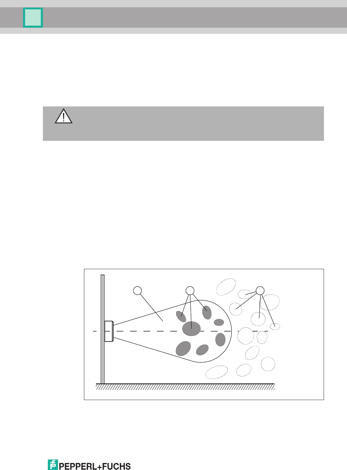
6.2 Basic Command Process
Interference Due to Multipath Propagation
The electromagnetic waves radiated by the read/write head do not just follow the direct route to
the tag, but are also reflected off objects in the vicinity, meaning that multiple partial waves
overlap with the waves radiated by the read/write head.
This overlap causes interference (i.e., exaggeration and dampening of the reception field
strength), leading to almost complete degradation. Depending on the environment, several
reflections may occur with differing intensity and distance. These different reflections lead to a
field strength in the measurement range that is difficult to predict. In the areas of degradation,
the prevailing field strength is weaker than the minimum detection field strength of the tag. As a
result, the tag cannot be activated for communication. Exaggeration of the field strength may
lead to unwanted excessive detection ranges.
1. Detection range
2. Degradation
3. Excessive detection ranges
Warning!
Hot surfaces
Be careful not to burn your fingers when handling the device! After shutting down the device,
wait at least half an hour before handling the device.
1 2 3

2017-12
38
IUH-F190-V1-*, IUT-F190-R4-V1*
Operation
The reflections and the resulting spatial inhomogeneity of the field strength depend on the
frequency used. The absolute value of the field strength depends on the transmission power.
Since the tags move in the measurement range of the read/write head, and the environment
can change, it is advisable to repeat the commands at different transmission frequencies and
at varying power. Different transmission frequencies are advisable, since the manufacturing
tolerances and the immediate environment of the tag have an effect on the tag's resonance
frequency.
Several Tags in the Measurement Range
Each read or write command can access one, several, or all tags in a measurement range. The
process is controlled by filter masks, which are managed via the commands Set Filter Mask
(FI) and Activate/Deactivate Filter (MF). These commands allow you to detect specific tags in
the measurement range. see chapter 6.5.
Read Algorithm
To communicate with tags with the maximum possible probability, the read/write head uses an
algorithm that varies the transmitting power and frequency. You can set the corresponding
values for this algorithm via the parameters Power Transmit (PT), Channel Frequency (CD), or
Number of Channels (NC) for the frequency hopping spread spectrum, and Number of
Attempts (TA). The number of set attempts is executed for each pairing of power and
frequency. This process takes a long time, but leads to a high read/write rate. The algorithm
runs through all combinations because it may be the case that a tag can be detected only by
one specific combination of power and frequency. This applies when the read/write head uses
a programmable frequency list as the frequency access method. This frequency list is defined
by parameter CD.
If the country identifier specifies a frequency hopping spread spectrum, the channels defined
there are used. This is not influenced by the programmable frequency list. You can adjust the
number of channels used for each attempt via the Number of Channels parameter (NC).
With the parameter Search Algorithm Cancellation Criteria (NT), you can specify the number of
tags to be processed. If you know the number of tags in the measurement range, you can use
this total number as the value for parameter NT. If the number of tags found corresponds to or
exceeds the value defined in parameter NT, the algorithm cancels any further runs to save time.
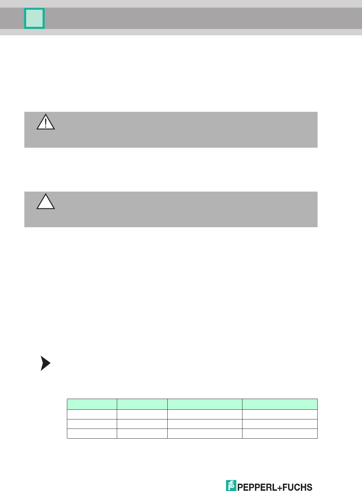
6.3 Command Overview
The commands in the list are described in detail on the following pages.
Read/Write Commands
Tip
If analysis of a specific application shows that a particular frequency and transmission power
are sufficient to execute commands successfully, the parameters can be set accordingly,
subject to national legislation. This measure reduces the processing time.
Abbreviation Command description
SF See "Single Read Read-Only Code SF" on page 39
EF See "Enhanced Read Read-Only Code EF" on page 39
SS See "Single Read Special Read-Only Code SS" on page 40
ES See "Enhanced Read Special Read-Only Code ES" on page 40
SP See "Single Write Special Read-Only Code SP" on page 41
SR, #SR See "Single Read Words SR" on page 42
ER, #ER See "Enhanced Read Words ER" on page 42
SW, #SW See "Single Write Words SW" on page 42

IUH-F190-V1-*, IUT-F190-R4-V1*
Operation
2017-12
39
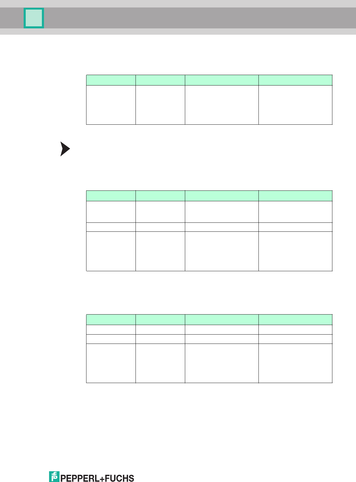
Filter Commands
Configuration Commands
6.4 Read/Write Commands
The tag's memory structure is based on the following read/write commands in accordance with
EPC Gen 2 (ISO/IEC 18000-63). See chapter 3.2.3.
Single Read Read-Only Code SF
One attempt is made to read a read-only code (TID). The read-only code is 4, 8, or 12 bytes
long, and comprises a 4-byte part number, which denotes the tag type, and optionally a tag
with a unique serial number of 4 or 8 bytes. Details see chapter 3.2.3.
<Length> = Length of the <Fixcode> in ASCII
hex
Example:
SF1 reads the read-only code to IDENTControl channel 1.
Enhanced Read Read-Only Code EF
This command continuously attempts to read a read-only code (TID). If a read-only code is
read, this is reported once. If there is no tag in the detection range, or if the tag leaves the
detection range, a status 5 message is reported.
<Length> = Length of the <Fixcode> in ASCII
hex
Example:
EF1 continuously reads the read-only code to IDENTControl Channel 1
EW, #EW See "Enhanced Write Words EW" on page 43
KI See "Kill UHF Tag KI" on page 43
Abbreviation Command description
FI See "Set Filter Mask FI" on page 44
MF See "Activate/Deactivate Filter MF" on page 45
Abbreviation Command description
RP See "Read Parameters" on page 49
WP See "Write Parameters" on page 49
Abbreviation Command description
Command: SF <ChanNo> <CHCK> <ETX>
Response: <Status> <ChanNo> <Luii> <UII> <Length>
<Fixcode> <CHCK> <ETX>
F <ChanNo> 0001 <CHCK> <ETX>
Command: EF <ChanNo> <CHCK> <ETX>
Response: <Status> <ChanNo> <Luii> <UII> <Length>
<Fixcode> <CHCK> <ETX>

2017-12
40
IUH-F190-V1-*, IUT-F190-R4-V1*
Operation
Single Read Special Read-Only Code SS
This command reads the UII segment from tags according to EPC Gen2 (ISO/IEC 18000-63).
Example:
SS10 reads the entire UII segment.
The tag type determines the maximum length of the UII/EPC. The actual length of the UII/EPC
is defined via the protocol control word <PC>. The data is structured as follows:
<Length> = Length of the <SpecialFixcode> in ASCII
hex
<SpecialFixcode> = <PC> & <UII/EPC>
<PC> corresponds to the protocol control word in accordance with EPC Gen 2 (ISO/IEC
18000-63), 2 bytes long.
<UII/EPC> contains the usage data.
Enhanced Read Special Read-Only Code ES
This command continuously attempts to read the UII segment from tags according to EPC Gen
2 (ISO/IEC 18000-63). If the <SpecialFixcode> of a tag is read, this is reported once. If there is
no tag in the detection range, or if the tag leaves the measurement range, a status 5 is reported.
Example:
ES10 continuously reads the UII segment.
The tag type determines the maximum length of the UII/EPC. The actual length of the UII/EPC
is defined via the protocol control word <PC>. The data is structured as follows:
<Length> = Length of the <SpecialFixcode> in ASCII
hex
<SpecialFixcode> = <PC> & <UII/EPC>
<PC> corresponds to the protocol control word in accordance with EPC Gen 2 (ISO/IEC
18000-63), 2 bytes long.
<UII/EPC> contains the usage data.
Command: SS <ChanNo> 0 <CHCK> <ETX>
Response: <Status> <ChanNo> <Length>
<SpecialFixcode> <CHCK> <ETX>
F <ChanNo> 0001 <CHCK> <ETX>
Note!
UII/EPC
If there are multiple tags in the measurement range with the same UII/EPC, the identical tags
are reported with Status A.
Command: ES <ChanNo> 0 <CHCK> <ETX>
Response: <Status> <ChanNo> <Length>
<SpecialFixcode> <CHCK> <ETX>
Note!
UII/EPC
If there are multiple tags in the measurement range with the same UII/EPC, the identical tags
are reported with Status A.

IUH-F190-V1-*, IUT-F190-R4-V1*
Operation
2017-12
41
Single Write Special Read-Only Code SP
This command writes a <Length> octet long UII/EPC code to tags according to EPC Gen 2
(ISO/IEC 18000-63).
The data length <Length> must be a whole number multiple of 2 octets because in accordance
with EPC Gen 2 (ISO/IEC 18000-63), <UII/EPC> must be written in 16-bit words. Only the
lengths 2
dec
, 4
dec
, ... 14
dec
(= 2
ASCII
, 4
ASCII
, ..., E
ASCII
) are permissible. The length is shown in
hexadecimal format, and includes the length of PC and UII/EPC. If a UII/EPC of 96 bits is
written, this results in 2 + 12 = 14 octets = E
ASCII
octet.
<Length> = Length of the <SpecialFixcode> in ASCII
hex
<SpecialFixcode> = <PC> & <UII/EPC>
<PC> corresponds to the protocol control word in accordance with EPC Gen 2 (ISO/IEC
18000-63), 2 octets long.
<UII/EPC> contains the usage data.
Example:
SP1E.30.00.30.14.F7.33.7C.00.1F.00.00.03.1C.6E writes the value ".30.00" for <PC>, and the
UII/EPC code ".30.14.F7.33.7C.00.1F.00.00.03.1C.6E" with a length of 2 + 12 octets = 14
octets to IDENTControl channel 1.
When using this command, make sure that the protocol control word contains the correct
length of the following UII/EPC. If this is not executed correctly, the complete data is not output
on the subsequent read operation because the command SS uses the length in the protocol
control word for the output.
In accordance with EPC Gen 2 (ISO/IEC 18000-63), the protocol control word consists of two
octets. The five highest value bits denote the length of the <UII/EPC> in words (= 16 bit):
The meaning of the remaining bits is described in EPC Gen 2 (ISO/IEC 18000-63). If a UII/EPC
has the length 12 octets, i.e., 6 words (00110
bin
), and all other bits are equal to 0, the protocol
control word corresponds to 00110000 00000000
bin
or 3000
hex
. If some of the other bits are
not equal to 0, this produces a different protocol control word.
Command: SP <ChanNo> <Length> <SpecialFixcode> <CHCK> <ETX>
Response: <Status> <ChanNo> <NUL> <Length> <SpecialFixcode> <CHCK> <ETX> F
<ChanNo> 0001 <CHCK> <ETX>
00000
bin
No word 0 bits
00001
bin
One word 16 bits
00010
bin
Two words 32 bits
... ... ...
11111
bin
31 words 496 bits
Note!
Several Tags in the Measurement Range
If there is more than one tag in the measurement range when this command is run, the UII is
written to the first tag only. Status A is output for all other tags.

2017-12
42
IUH-F190-V1-*, IUT-F190-R4-V1*
Operation
Single Read Words SR
One attempt is made to read <WordNum> 32-bit words from address <WordAddr>.
Example:
SR1000101 reads a 4-byte word from memory address "0001."
Enhanced Read Words ER
Continuous attempts are made to read <WordNum> 32-bit words from the address
<WordAddr>. Only changing data is transferred via the interface. When a read/write tag leaves
the read range, status 5 is output.
Example:
ER1000101 continuously reads a 4-byte word from memory address "0001".
Single Write Words SW
One attempt is made to write <WordNum> 32-bit words from the address <WordAddr>.
Example:
SW1000101ABCD writes the 4-byte-long word "ABCD" from memory address "0001".
Command: SR <ChanNo> <WordAddr> <WordNum>
<CHCK> <ETX>
Response: <Status><ChanNo><Luii><UII><Ldata><Data
><CHCK> <ETX>
F <ChanNo> 0001<CHCK> <ETX>
Note!
The memory bank (MB) parameter defines the bank accessed by this command. see
"Memory Module for Tag Accesses to the "Memory Bank" MB" on page 52.
Command: ER <ChanNo> <WordAddr> <WordNum>
<CHCK> <ETX>
Response: <Status><ChanNo><Luii><UII><Ldata><Data
><CHCK> <ETX>
Note!
The memory bank (MB) parameter defines the bank accessed by this command. see
"Memory Module for Tag Accesses to the "Memory Bank" MB" on page 52.
Command: SW <ChanNo> <WordAddr> <WordNum>
<Data> <CHCK> <ETX>
Response: <Status> <ChanNo> <Luii> <UII> <CHCK>
<ETX>
F <ChanNo> 0001 <CHCK> <ETX>
Note!
The memory bank (MB) parameter defines the bank accessed by this command. see
"Memory Module for Tag Accesses to the "Memory Bank" MB" on page 52.

IUH-F190-V1-*, IUT-F190-R4-V1*
Operation
2017-12
43
Enhanced Write Words EW
This command continuously attempts to write <WordNum> 32-bit words from the address
<WordAddr>. If the command was executed successfully, a status 0 is reported. If there is no
tag in the detection range, or if the tag leaves the detection range, a status 5 is reported.
Example:
EW1000101ABCD continuously writes the 4-byte long word "ABCD" from memory address
"0001".
Kill UHF Tag KI
This command sets a UHF tag to a state where no further access is possible. The command
can be executed only if a valid password has previously been set in segment Bank 00 via the
command SW. See chapter 3.2.3. The password must have at least 1 non-zero bit.
<UIILength> = Mask length for the UII/EPC in bits, values: 00 ... FF, always begins at Address 0.
The information is entered as 2 hex
ASCII
characters.
<UIIData> = Specification of the mask for the UII, in octets
<PassWord> = Password for killing a UHF tag, 4 octets
<RecomBits> = Recommission bits, always set to zero
Note!
When writing to the UII/EPC area (MB = 1), note that it is not possible to write to the CRC. The
first writable address is 0x0001. The protocol control word <PC> begins at this address. Use
the command #SW.
Command: EW <ChanNo> <WordAddr> <WordNum>
<Data> <CHCK> <ETX>
Response: <Status> <ChanNo> <Luii> <UII><CHCK>
<ETX>
Note!
The memory bank (MB) parameter defines the bank accessed by this command. see
"Memory Module for Tag Accesses to the "Memory Bank" MB" on page 52.
Note!
16-Bit Read/Write Commands
The read/write commands SR, ER, SW, and EW are interpreted as 16-bit versions by means of
a preceding # symbol.
The 16-bit read/write commands behave in the same way as the 32-bit versions.
■
16-bit commands write or read a word with a length of 2 bytes.
■
32-bit commands write or read a word with a length of 4 bytes.
Example:
#SW1000202ABCD corresponds to SW1000101ABCD
Command: KI <ChanNo>.30.30 <UIILength>< UIIData>
<PassWord> <RecomBits> <CHCK> <ETX>
Response: <Status> <ChanNo> <Luii> <UII> <CHCK>
<ETX>
F <ChanNo> 0001 <CHCK> <ETX>

2017-12
44
IUH-F190-V1-*, IUT-F190-R4-V1*
Operation
Example:
KI10018.E2.00.90abcd.00 kills a UHF tag with a UII starting ".E2.00.90" and using the
password "abcd."
6.5 Filter Commands
Each read or write command can access one, several, or all tags in a measurement range. The
process is controlled by filter masks, which are managed via the commands Set Filter Mask
(FI) and Activate/Deactivate Filter (MF). These commands allow you to detect specific tags in
the measurement range. see chapter 6.5.
Set Filter Mask FI
Using command FI, you can define a filter mask for accessing the tags located in the box. You
can define up to 3 filters (0-2). The following syntax is used:
<MemBank> = Memory segment to which the filter is to be applied. The information is entered
as one hex
ASCII
character.
<StartAddress> = Address of the bit at which the filter mask begins. Specified in hex
ASCII
.
Values: 0000 FFFF
<MaskLength> = Length of the mask in bits. The information is entered as 2 hex
ASCII
characters.
<MaskData> = Defines the actual filter mask
Example:
There are three tags in the measurement range of the read/write head. Each tag has a unique
identifier of <PC> & <UII/EPC>:
If you want to detect the 3rd tag, the filter mask is: FI101000001028.34.00.E2.00.90
Meaning of Bits
Command: FI <ChanNo> <FilterNumber> <MemBank>
<Negate> <LogicalOperation> 0
<StartAddress> <MaskLength> <MaskData>
<CHCK> <ETX>
Response: <Status> <ChanNo> <CHCK> <ETX>
<PC> & <UII/EPC>
1. Tag .34.00.E2.00.92.01.20.51.70.00.00.00.02.76
2. Tag .34.00.E2.00.92.01.20.51.70.00.00.00.02.66
3. Tag .34.00.E2.00.90.51.33.02.00.92.18.20.56.15
Command FI = Command
<ChanNo> 1= Channel 1
<FilterNumber> 0= First filter used, filter number = 0
<MemBank> 1= Memory bank 01; should be filtered to
UII/EPC
<Negate> 0= Not negated
<LogicalOperation> 0= OR link
not relevant here because only one filter is set
00= Value is always 0
<StartAddress> 0010 = Start address 10
hex
or bit 16

IUH-F190-V1-*, IUT-F190-R4-V1*
Operation
2017-12
45
Owing to the structure of the memory bank for UII/EPC ( see image on page 12), the start
address is located at bit 16. The CRC-16 value occupies the memory position from bit 0
through bit 15; the PC starts at bit 16.
If you activate the filter with the command MF, and then execute command SS10, you receive
only one response from the corresponding tag even if other tags are located in the
measurement range:
.34.00.E2.00.90.51.33.02.00.92.18.20.56.15
The value <Negate> controls the mask comparison. 0 = not negated, 1 = negated. If you
negate the filtering by setting the value <Negate> in the command
FI101100001028.34.00.E2.00.90, you receive a response from the tags that does not match
the filter:
.34.00.E2.00.92.01.20.51.70.00.00.00.02.76
.34.00.E2.00.92.01.20.51.70.00.00.00.02.66
If you prefer to filter only at the start of <UII/EPC>, and ignore the <PC>, send the command
FI101000002018.E2.00.90. The start address is 20
hex
, the mask length has 24 bits, and the
mask is .E2.00.90.
The value <LogicalOperation> logically links several filters with each other and is evaluated
only if more than one filter is used. If only one filter is used, this value is ignored. 0 = OR, 1 =
AND
Other examples include:
FI102000000018.E2.00.10 sets filter 0 so that all tags with a TID beginning with .E2.00.10 are
detected.
FI111100002008.22 sets filter 1 so that all tags whose UII/EPC do not begin .22 are detected.
FI1010100010700.00123456789012 sets filter 0 so that the tag with the SpecialFixcode
(PC+UII/EPC) 0.00123456789012 is detected.
The letter x can be used as a wildcard for the channel and filter number. Command
FIxx0000000000 resets the three filters for all IDENTControl channels.
Activate/Deactivate Filter MF
Command MF activates or deactivates the filter masks.
The following values are possible:
0 = Deactivate filter masks
1 = Activate filter masks - mode 1
2 = Activate filter masks - mode 2
Example:
MF11 activates the filter masks for IDENTControl channel 1
<MaskLength> 28 = Mask length, 28
hex
= 40
dec
, i.e., 40 bits
<MaskData> 34.00.E2.00.90 = Actual Mask
Command: MF<ChanNo><Value><CHCK><ETX>
Response: <Status><ChanNo><CHCK><ETX>
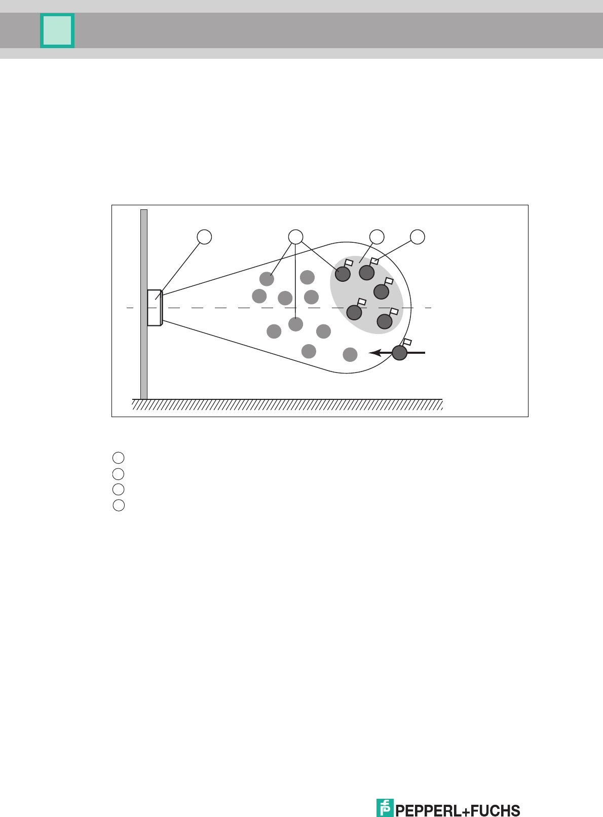
2017-12
46
IUH-F190-V1-*, IUT-F190-R4-V1*
Operation
Command MF - Mode 1
In total, there are 15 tags in the measurement range of the read/write head, with three groups of
five marked as either A, B, or C. The filter is now set to "B" by the command FI.
If you execute command MF11 (Activate Filter - Mode 1), this command affects all subsequent
commands.
If a write command is executed next, all "B" tags in the measurement range are selected and
are assigned a 'Selected' flag. The write command is executed only for tags with a Selected
flag.
When the filter is set to "B", command MF11 (Filter Activated - Mode 1) selects all "B" tags; the
following commands address the selected "B" tags.
Command MF - Mode 2
In total, there are 15 tags in the measurement range of the read/write head, with three groups of
five marked as either A, B, or C. The filter is set to "B" by command FI.
If you execute command MF12 (Activate Filter - Mode 2), this command affects all subsequent
commands.
If a write command is executed next, all tags in the measurement range that are not "B" tags are
selected. These tags are assigned a 'Selected' flag. The write command is executed only for
tags with no Selected flag.
Read/write head
Tags "A", "B", "C"
Filter mask
Selected flag
1 3
A
A
A
A
B
C C
C
C
C
AB
B
B
B
2
4
D
1
2
3
4
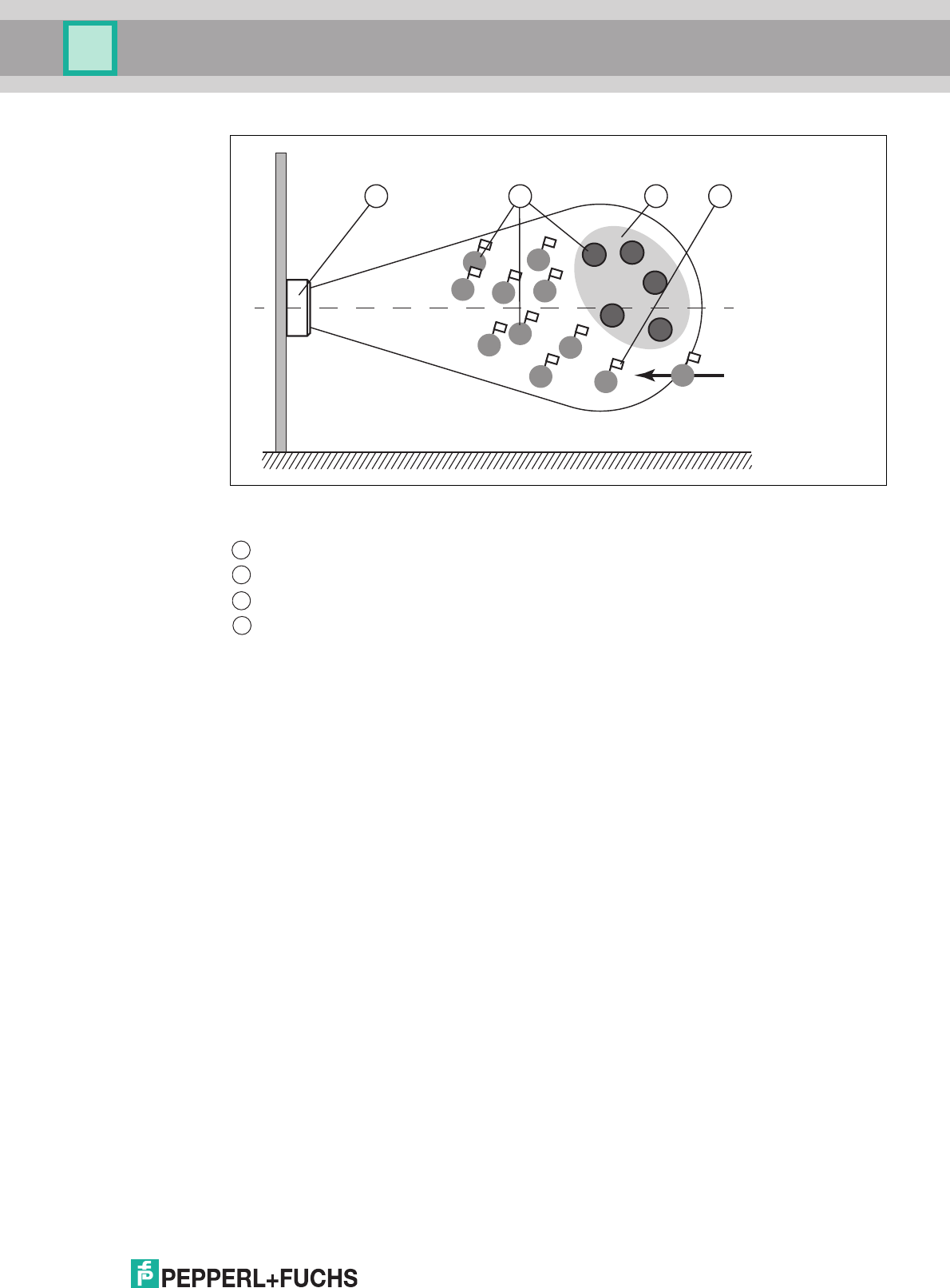
IUH-F190-V1-*, IUT-F190-R4-V1*
Operation
2017-12
47
When the filter is set to "B," command MF12 (Filter Activated - Mode 2) selects all "A" and "C"
tags, and the following commands address the unselected "B" tags.
Difference Between Command MF - Mode 1 and Command MF - Mode 2
In both cases, the subsequent commands are applied only to the "B" tags in the measurement
range.
With MF11, "B" tags are assigned a Selected flag. With MF12, "B" tags are not assigned a
Selected flag.
If a "D" tag with a Selected flag from the operation of a different read/write head enters the
measurement range, this "D" tag will execute the subsequent commands if MF11 is activated. If
MF12 is activated, this "D" tag will not execute the subsequent commands.
6.6 Configuration Commands
The response to a configuration command is a status message from the read/write head.
During the read operation, a status message and the corresponding data are received as the
response.
Read/write head
Tags "A", "B", "C"
Filter mask inverted
Selected flag
1 3
A
A
A
A
B
CC
C
C
C
AB
B
B
B
2
D
4
1
2
3
4

2017-12
48
IUH-F190-V1-*, IUT-F190-R4-V1*
Operation
6.6.1 Read and Write Parameters
With the read parameter (RP) and write parameter (WP) configuration commands, you can
read/write the following parameters:
The parameters are saved in the read/write head as nonvolatile.
Abbreviation Page Parameter is readable/writeable
AP See "Antenna Polarization AP" on
page 49
Readable/writeable
CD See "CD Transmission Channels" on
page 50
Readable/writeable for RC = 1, 4, 5, 6,
8
Readable for RC = 2, 3, 7, 9, 10, 11,
12, 13, 14
E5 See "Number of Unsuccessful
Attempts until Status 5 "Enhanced
Status 5" E5" on page 50
Readable/writeable
FL See "Read Out Filter Mask "Filter List"
FL" on page 51
Readable
IF See "Output Additional Information,
"Information" IF" on page 51
Readable/writeable
MB See "Memory Module for Tag
Accesses to the "Memory Bank" MB"
on page 52
Readable/writeable
MD See "Retrieve Additional Information
MD" on page 52
Readable
MF See "Measurement of Reflected
Transmitting Power "Measure
Reflection" MF" on page 52
Readable
NC See "Number of Channels NC" on
page 53
Readable/writeable for RC = 2, 3, 7, 9,
10, 11, 12, 13, 14
Readable for RC = 1, 4, 5, 6, 8
NT See "Search Algorithm Cancellation
Criteria "number of tags to find" NT"
on page 53
Readable/writeable
PT See "Transmission Power "Power
Transmit" PT" on page 54
Readable/writeable
QV See "Protocol Mode QV" on page 55 Readable/writeable
QW See "Q Value QW" on page 57 Readable/writeable
RC See "Country Identifier, "Region
Code"" on page 57
Readable
RD See "Reset to Default, RD" on page 58 Writeable
SM See "Transmission Pauses in
"Sensing Mode" SM" on page 59
Readable/writeable
TA See "Number of Attempts "Tries
Allowed" TA" on page 59
Readable/writeable

IUH-F190-V1-*, IUT-F190-R4-V1*
Operation
2017-12
49
Read Parameters
The RP command reads configuration parameters from the read/write head.
<SystemCode> = U
ASCII
for IUH-*
<ParamTyp> = 2 bytes ASCII
<DataLength> = Length of <Data> in command, 2 bytes binary
<Data> = Optional additional information
Example:
RP1UE5.00.00 outputs the number of unsuccessful read attempts until status 5.
Write Parameters
Command WP writes configuration parameters to the read/write head.
<SystemCode> = U
ASCII
for IUH-*
<ParamTyp> = 2 bytes ASCII
<DataLength> = Length of <Data>, 2 bytes binary
<Data> = Optional additional information
Example:
WP1UE5.00.01.05 sets the number of unsuccessful read attempts to status 5 on 5 attempts.
6.6.2 Parameters
Antenna Polarization AP
This parameter switches polarization to horizontally linear, vertically linear, or combined mode,
or reads out the polarization currently set.
Example:
WP1UAP.00.01H switches the polarization to horizontally linear
WP1UAP.00.01C switches the polarization to combined mode
RP1UAP.00.00 reads out the set polarization
Command: RP <ChanNo> <SystemCode> <ParamTyp>
<DataLength> <Data> <CHCK> <ETX>
Response: <Status> <ChanNo> <Data> <CHCK> <ETX>
Command: WP <ChanNo> <SystemCode> <ParamTyp>
<DataLength> <Data> <CHCK> <ETX>
Response: <Status> <ChanNo> <CHCK> <ETX>
ParamTyp: AP
Default: AP = C
Value range: C = combined
1
H = Horizontally linear
V = Vertically linear
1.Combined horizontally linear and vertically linear for each read/write attempt

2017-12
50
IUH-F190-V1-*, IUT-F190-R4-V1*
Operation
Set the polarization according to the read/write tag used (see chapter 4.3.3). You can achieve a
better detection range if the polarization of the read/write head corresponds to the polarization
of the read/write tag.
Set the polarization to combined mode if the orientation of the tag is not known. In combined
mode, first horizontal polarization and then vertical polarization is used for each read/write
attempt. This achieves the same results as when circular polarization is used. The duration of
the read/write operation is extended in combined mode.
CD Transmission Channels
Frequency Access Method Programmable frequency list:
This parameter sets the number and sequence of transmission channels or reads out the
number and sequence of transmission channels.
Frequency Access Method Frequency hopping spread spectrum:
This parameter reads out the number and sequence of transmission channels for the
frequency hopping spread spectrum.
Example:
WP1UCD.00.04.07.0A.04.0D defines the sequence 7, 10, 4, and 13 as the permitted
transmission channels
WP1UCD.00.01.0A allows the read/write head to use only transmission channel 10
RP1UCD.00.00 reads out the sequence of permitted transmission channels
Number of Unsuccessful Attempts until Status 5 "Enhanced Status 5" E5
This parameter sets the number of unsuccessful read/write attempts until a status 5 is output for
an enhanced command, or outputs the number.
Status 0 and status A depend on this parameter, and are output immediately.
Example:
WP1UE5.00.01.05 sets the number to 5 unsuccessful read/write attempts until a status 5 is
output
RP1UE5.00.00 outputs the number
If the number of read/write attempts is reduced:
Faster response time in enhanced mode.
ParamTyp: CD
Default: Depending on the country-specific settings,
see chapter 3.3.
Value range: Depending on the country-specific settings,
see chapter 3.3.
Tip
If you have parameterized several transmission channels with the parameter CD, the read/write
head executes each write or read command on all defined transmission channels sequentially
according to the defined sequence. If several additional transmission power values are
parameterized (see "Transmission Power "Power Transmit" PT" on page 54), all set
transmission powers are executed on each transmission channel for each read or write
command. See chapter 6.2.
ParamTyp: E5
Default: E5 = 5
Value range: 0 ... 252

IUH-F190-V1-*, IUT-F190-R4-V1*
Operation
2017-12
51
Status 5 messages in the event of unstable tag reading.
Read Out Filter Mask "Filter List" FL
Parameter FL contains the current configuration of the filter masks as set during execution of
command FI. The output format corresponds to the data input format of command FI without
the filter number. The parameter can only be read, but not set.
Example:
RP1UFL.00.01.02 outputs the current configuration of filter 2
Output Additional Information, "Information" IF
Parameter IF allows you to output additional information providing that the reading was
successful and the multiframe protocol is activated. See "Protocol Mode QV" on page 55. The
additional information is the RSSI value of the reading, the transmission channel used, and
transmitting power of this reading.
Example:
WP1UIF.00.01.01 prompts the read/write head to output additional information after each
successful reading.
RP1UIF.00.00 outputs the value of parameter IF.
The additional information is output in the following format:
B<ChanNo> <InfoTyp> <RSSI> <TxChannel> <TxPower>
To distinguish the additional information from the standard outputs, the output begins with the
status B as the first ASCII character, followed by the IDENTControl channel. This is followed by
the <InfoTyp>, which indicates that this is a type .01 information frame. The output ends with
the RSSI value (1 byte), the transmission channel used (1 byte), and the power used (2 bytes).
The RSSI value is between 0 (= low) and 100 (= high).
Meaning of the bytes in response .42.31.01.1A.0D.00.14
ParamTyp: FL
Value range: 0 ... 2
Response: <Status><ChanNo><MemBank><Negate><L
ogicalOperation>0<StartAddress><MaskLen
gth><MaskData><CHCK><ETX>
ParamTyp: IF
Default: IF = 0
Value range: 0, 1
.42 = Status B
ASCII
to identify the additional information
.31 = 1
ASCII
, IDENTControl channel 1
.01 = The information type
.1A = 26
dec
, RSSI value
.0D = 13
dec
, tag access to transmission channel 13
.00.14 = 20
dec
, transmission power 20 mW

2017-12
52
IUH-F190-V1-*, IUT-F190-R4-V1*
Operation
Memory Module for Tag Accesses to the "Memory Bank" MB
This parameter specifies the bank accessed by the read/write commands SR, ER, SW, and
EW. See chapter 3.2.3.
Example:
WP1UMB.00.01.03 sets the bank to User Memory
Retrieve Additional Information MD
This parameter allows you to retrieve information about the last successful tag access. This
returns the RSSI value with a length of 1 byte, the transmission channel used with a length of 1
byte, and the transmitting power with a length of 2 bytes. The RSSI value may be between 0 (=
low) and 100 (= high).
Parameter MD allows the same data to be accessed in the single-frame protocol as is available
in the multiframe protocol with parameter IF. See "Protocol Mode QV" on page 55 and see
"Output Additional Information, "Information" IF" on page 51.
Example:
RP1UMD.00.01.01 returns the response .30.01.13.04.00.32
Explanation of the response:
<Status> = 0
<ChanNo> = 1
<RSSI> =. 13 = 19
dec
<TXChannel> =. 04
<TXPower> = .00.32 = 50
dec
mW
Measurement of Reflected Transmitting Power "Measure Reflection" MF
This parameter measures the reflected transmitting power of the antenna and the environment.
The results are output as one byte per transmission channel. The transmission channels are
dependent on the country-specific settings, see chapter 3.3.
The parameter is not output for the "combined" antenna polarization.
To obtain the reflected power in dBm, subtract the value 100 from the return value in decimal
notation.
Example:
ParamTyp: MB
Default: MB = .03 = User Memory
Value range: .00 = reserved (password area)
.01 = UII/EPC
.02 = TID
.03 = User Memory
ParamTyp: MD
ParamTyp: MF
Value range: -18 .. +21 dBm
1
1.0 or 255 is returned for values outside the value range

IUH-F190-V1-*, IUT-F190-R4-V1*
Operation
2017-12
53
If the country identifier RC = 01 (= 4 channels), RP1UMF.00.00 returns the response
01.63.64.67.65
Explanation of the response:
<Status> = 0
<ChanNo> = 1
<PCh04> = .63 = 99
dec
results in 99 - 100 = -1 dBm
<PCh07> = .64 = 100
dec
results in 100 - 100 = 0 dBm
<PCh10> = .67 = 103
dec
results in 103 - 100 = +3 dBm
<PCh13> = .65 = 101
dec
results in 101 - 100 = +1 dBm
Number of Channels NC
Frequency Access Method Frequency hopping spread spectrum:
Parameter NC indicates the number of channels on which a write or read attempt is performed.
If the value 4 is set, the read/write head attempts to read the tag on 4 different frequencies
when a read command is given. The parameter can be read and written.
Frequency Access Method Programmable frequency list:
The parameter can be read only. The parameter specifies the number of transmission channels
on which parameter CD is set.
Example:
WP1UNC.00.01.02 allows two channels for a read attempt.
RP1UNC.00.00 reads out the permitted number of channels set.
Search Algorithm Cancellation Criteria "number of tags to find" NT
Parameter NT specifies the number of tags in the measurement range that the read/write head
searches for. Each command is repeated in accordance with the parameters Transmission
Power (PT), Transmission Channel (CD) or Number of Channels (NC), and Number of
Attempts (TA) (see chapter 6.2). If the number of tags found during the repeat operations
reaches or exceeds the NT value, all further runs are canceled. The command is canceled, and
the data is output.
If the number of tags is set to 255 (= .FF), the function is deactivated. This parameter does not
affect "enhanced" commands, but only "single" commands.
Example:
The value WP1UNT.00.01.05 sets the number of tags in the measurement range for which the
read/write head searches to 5.
RP1UNT.00.00 outputs the set value.
ParamTyp: NC
Default setting: NC = 4
Value range: 1 50
ParamTyp: NT
Default: NT = 255
Value range: 0 ... 254, 255 = off
2017-12
54
IUH-F190-V1-*, IUT-F190-R4-V1*
Operation
Transmission Power "Power Transmit" PT
This parameter sets the transmission power in mW or reads out the transmission power set.
Example:
WP1UPT.00.02.00.32 sets the transmission power to 50 mW
RP1UPT.00.00 reads out the transmission power currently set
Higher detection range if you increase the transmission power.
Possible excessive detection ranges if you increase the transmission power.
Adjacent read/write heads might be affected if the range increases.
ParamTyp: PT
Default: Depending on the country-specific settings,
see chapter 3.3.
Value range: Depending on the country-specific settings,
see chapter 3.3.
Tip
The highest transmission power does not necessarily lead to the largest read range. Vary the
transmission power to achieve the optimum read result.
Note!
You can operate the read/write head only with internally specified transmission power. You can
use the command WP1UPT.00.02.xx.xx in the software to enter any transmission power within
the specified range of values. The read/write head automatically sets the transmission power to
the next lowest value available. Any entries outside the specified value range are returned as
errors. Command RP1UPT.00.00 allows you to read out the power value that is currently set.
Tip
You can parameterize the read/write head with several transmission power values:
Command WP1UPT.00.06.00.14.00.32.00.64 sets 3 transmission power values for 20 mW, 50
mW, and 100 mW. Each read and write command is executed in succession for all 3
transmission power values. If 1 or more tags are found and successfully read/written for the first
transmission power, the command is still executed with all other transmission powers to reach
any other tags that may be available.
You can specify a maximum of 10 transmission power values. If several additional transmission
channels are selected (see "CD Transmission Channels" on page 50), all set powers are
executed on each transmission channel for each read or write command. See chapter 6.2.

IUH-F190-V1-*, IUT-F190-R4-V1*
Operation
2017-12
55
Protocol Mode QV
Parameter QV toggles the output protocol between single frame and multiframe.
In single-frame protocol, the output corresponds to the Pepperl+Fuchs standard in LF and HF
systems. If there is more than one tag in the measurement range, status A is output as a
warning.
In the multiframe protocol, each tag that responded is output. An output is then issued which
begins with status F, contains the number of responses, and completes the full command
output.
Example:
WP1UQV.00.01.4D sets the protocol to multiframe.
RP1UQV.00.00 outputs the set protocol mode.
If QV = M, the following responses are made to a single read command (SR):
One read command was executed to which three tags responded. For each tag, the status, the
IDENTControl channel, the length of the UII, the UII, the length of the data, and the read data
are output. Then an output is issued with status F, the IDENTControl channel, and the number
of tags that responded.
<Luii> = Length of <UII> in bytes, 2 bytes
<Ldata> = Length of <data> in bytes, 2 bytes
ParamTyp: QV
Default: QV = .4D
Value range: .53 = S for single-frame protocol
.4D = M for multiframe protocol
Response: 0<ChanNo><Luii><UII1><Ldata><data><CH
CK><ETX>
0<ChanNo><Luii><UII2><Ldata><data><CH
CK><ETX>
0<ChanNo><Luii><UII3><Ldata><data><CH
CK><ETX>
F<ChanNo>0003<CHCK><ETX>

2017-12
56
IUH-F190-V1-*, IUT-F190-R4-V1*
Operation
Responses Depending on Protocol Mode QV
Command
Parameter QV
Single-frame protocol Multiframe protocol
Responses
SS No tag:
5<ChanNo>
One tag:
0<ChanNo><UII>
Two tags:
A<ChanNo>
No tag:
F<ChanNo>0000
Two tags:
0<ChanNo><Luii><UII1>
0<ChanNo><Luii><UII2>
F<ChanNo>0002
SR, #SR
SF
No tag:
5<ChanNo>
One tag:
0<ChanNo><data>
Two tags:
A<ChanNo>
No tag:
F<ChanNo>0000
Two tags:
0<ChanNo><Luii><UII1><Ldata><data>
0<ChanNo><Luii><UII2><Ldata><data>
F<ChanNo>0002
SW, #SW No tag:
5<ChanNo>
One tag:
0<ChanNo>
Two tags:
A<ChanNo>
No tag:
F<ChanNo>0000
Two tags:
0<ChanNo><Luii><UII1>
0<ChanNo><Luii><UII2>
F<ChanNo>0002
ES No tag:
5<ChanNo>
One tag added:
0<ChanNo><UII>
One tag added:
A<ChanNo>
One tag removed:
0<ChanNo><UII>
All tags removed:
5<ChanNo>
No tag:
5<ChanNo>
Two tags added:
0<ChanNo><Luii><UII1>
0<ChanNo><Luii><UII2>
Tag 1 removed:
5<ChanNo><Luii><UII1>
Tag 3 added:
0<ChanNo><Luii><UII3>
Tag 4 added (UII same as tag 2):
A<ChanNo><Luii><UII2>
All tags removed:
5<ChanNo><Luii><UII2>
5<ChanNo><Luii><UII3>
5<ChanNo><Luii><UII2>
SP No tag:
5<ChanNo>
One tag added:
0<ChanNo>
One tag added:
A<ChanNo>
No tag:
F<ChanNo>0000
One tag added:
0<ChanNo><NUL><Luii><UII1>
F<ChanNo>0001
One tag added:
0<ChanNo><NUL><Luii><UII1>
A<ChanNo><NUL><Luii><UII2>
F<ChanNo>0002
Table 6.1 <CHCK><ETX> omitted at the end of each response due to space requirements

IUH-F190-V1-*, IUT-F190-R4-V1*
Operation
2017-12
57
Q Value QW
In accordance with EPC Gen 2 (ISO/IEC 18000-63), the slotted ALOHA principle is used for
anticollision. The number of time slots is defined as 2
Q
. The parameter QW defines the Q
value. As a guide, the number of time slots should roughly correspond to the number of
expected tags in the measurement range.
Example:
WP1UQW.00.01.04 sets the Q value to 4. The read/write head therefore works with 2
4
= 16
time slots.
RP1UQW.00.00 outputs the set Q value.
Country Identifier, "Region Code"
The RC parameter reads out the country identifier.
Example:
RP1URC.00.00 reads out the set country identifier.
The country identifier consists of 2 bytes. The first byte always has the value 80. The second
byte corresponds to the country identifier. The serial response .30.31.80.01 indicates the
country identifier for Europe.
Country Identifiers for IUH-F190-V1-FR1* and IUT-F190-R4-V1-FR1*
ParamTyp: QW
Default: QW = 2
Value range: 0 ... 7
ParamTyp: RC
Value range: See the following table “country identifiers”
Country
Identifier
Occupied Frequency Bandwidth
Frequency Access Method Country or Region
01 865.6 MHz – 867.6 MHz
Parameterizable frequency list
EU and other countries
subject to EN 302208
04 865.0 MHz – 867.0 MHz
Parameterizable frequency list
India
05 866.0 MHz – 868.0 MHz
Parameterizable frequency list
Singapore, Vietnam
06 866.0 MHz – 867.6 MHz
Parameterizable frequency list
Russia
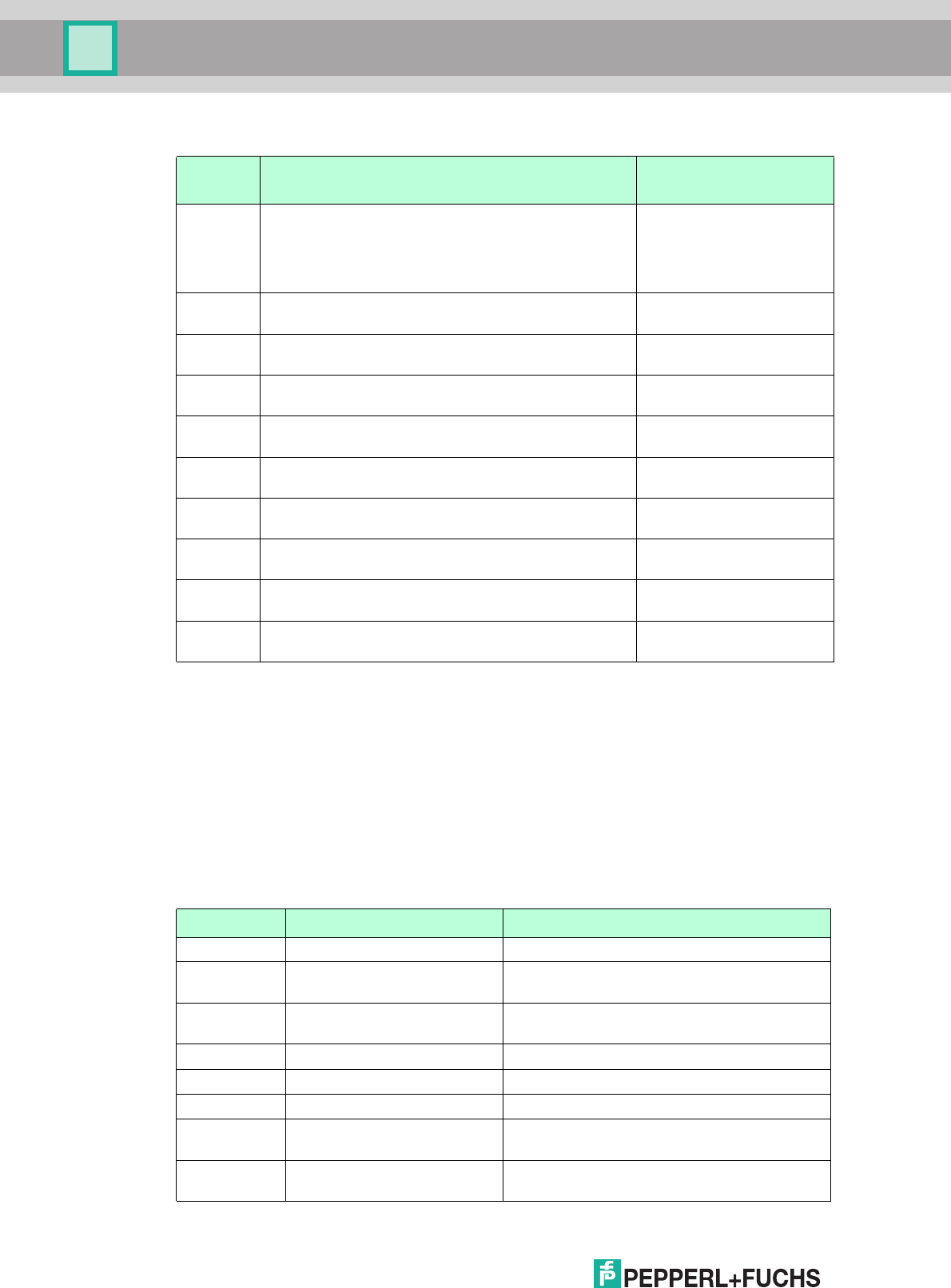
2017-12
58
IUH-F190-V1-*, IUT-F190-R4-V1*
Operation
Country Identifiers for IUH-F190-V1-FR2* and IUT-F190-R4-V1-FR2*
Reset to Default, RD
This parameter returns all settings of the read/write head to the default configuration.
Example:
WP1URD.00.00
Default Value Parameters
Country
Identifier
Occupied Frequency Bandwidth
Frequency Access Method Country or Region
02 902 MHz – 928 MHz
Frequency hopping spread spectrum
USA
Canada
Mexico
Argentina
Colombia
03 920 MHz – 925 MHz
Frequency hopping spread spectrum
China
07 915 MHz – 928 MHz
Frequency hopping spread spectrum
Brazil
08 916.7 MHz – 920.5 MHz
Parameterizable frequency list
Japan
09 917.2 MHz – 920.4 MHz
Frequency hopping spread spectrum
South Korea
10 920 MHz – 926 MHz
Frequency hopping spread spectrum
Australia
11 921.5 MHz – 928 MHz
Frequency hopping spread spectrum
New Zealand
12 920 MHz – 925 MHz
Frequency hopping spread spectrum
Hong Kong
Thailand
13 919 MHz – 923 MHz
Frequency hopping spread spectrum
Malaysia
14 920 MHz – 925 MHz
Frequency hopping spread spectrum
Singapore
Vietnam
Table 6.2 For technical details regarding the regional settings, see chapter 3.3.
ParamTyp: RD
Abbreviation Parameter Default value
AP Antenna Polarization AP Combined mode (C)
CD Transmission Channels Depending on the country-specific settings,
see chapter 3.3
E5 Number of unsuccessful
attempts up to Status 5
5
FL Read Out Filter Mask No filter set (0)
IF Output Additional Information Off (0)
MB Memory Bank User Memory (3)
MD Retrieve Additional
Information MD
Not applicable
MF Measurement of Reflected
Transmission Power
Not applicable

IUH-F190-V1-*, IUT-F190-R4-V1*
Operation
2017-12
59
Transmission Pauses in "Sensing Mode" SM
The parameter SM defines a pause time in milliseconds. This pause time is executed once all
runs are complete.
This parameter is especially useful for continuous operation with "enhanced" commands (see
chapter 6.4). If you specify transmission pauses, you can operate the read/write head at higher
ambient temperatures.
Example:
WP1USM.00.02.27.10 sets the pause time to 10,000 ms = 10 seconds.
RP1USM.00.00 reads out the pause time.
Number of Attempts "Tries Allowed" TA
This parameter sets the permitted number of write or read attempts, or outputs the permitted
number of attempts.
Example:
WP1UTA.00.01.01 permits precisely one attempt (= no repeats)
NC Number of Channels Depending on the country-specific settings,
see chapter 3.3
NT Search Algorithm
Cancellation Criteria
Off (255)
PT Power Transmit Depending on the country-specific settings,
see chapter 3.3
QV Protocol Mode QV Multiframe Protocol (M)
QW Q Value 2
RC Country Identifier, "Region
Code"
Not applicable
RD Reset to Default Not applicable
SM Transmission Pauses in
"Sensing Mode"
0
TA Number of Attempts, "Tries
Allowed" TA
2
ParamTyp: SM
Default: SM = 100 ms
1
SM = 0 ms
2
1.For all FR1 read/write heads
2.For all FR2 read/write heads
Value range: 100 ms ... 65,535 ms, 2 bytes
3
0 ms ... 65,535 ms, 2 bytes
4
3.For all FR1 read/write heads
4.For all FR2 read/write heads
ParamTyp: TA
Default: TA = 2
Value range: 1 ... 255
Abbreviation Parameter Default value

2017-12
60
IUH-F190-V1-*, IUT-F190-R4-V1*
Operation
WP1UTA.00.01.03 permits 3 attempts
RP1UTA.00.00 outputs the permitted number of attempts
If the permitted number of write or read attempts between the read/write head and the tag is
increased, this results in:
More reliable reading and writing.
Increased response time.
6.7 Read/Write Head IUT-F190-R4-V1-* with Integrated RS-485 Interface
The IUT-F190-R4-V1-* read/write head is connected to the RS-485 serial interface of the
parent device via a point-to-point connection. The read/write head has an internal terminator on
the RS-485 interface. Only 1 read/write head can be connected within an RS-485 network. It is
not possible to build an RS-485 network with multiple read/write heads.
The read/write head can be used in single-drop-mode and in multi-drop mode. In single-drop-
mode, the read/write head first executes the respective command and then sends the
response. This may take a few seconds. In multi-drop mode, the read/write head immediately
sends the confirmation that the read head has understood the command. The read head then
starts to execute the command. The actual result of the command must be queried by polling
the read/write head.
The IUT-F190-R4-V1-* read/write head is set to single-drop mode at the factory.
Define Function DF
This command is used to switch operating mode:
Single-drop --> Multi-drop
Multi-drop --> Single-drop
After changing the operating mode, a power supply reset or an "RS" command must be
executed to activate the required operating mode.
6.7.1 Single-drop mode
In this operating mode, the read/write head first executes a command and then sends the
response. This may take a few seconds. The command syntax is identical to the syntax of the
read/write heads with the IDENTControl control interface, but does not contain the channel
number <ChanNo>.
Note!
If you use an RS-485/RS-422 to RS-232 converter with automatic baud rate and mode
detection, communication problems may occur due to incorrect detection of these parameters.
In this case, select the operating mode of the converter manually.
Command: DF42 <CHCK> <ETX>
Command: DF <DeviceNo> 41 <CHCK> <ETX>
Example!
Command: <CommandCode> <CommandParameters> <CHCK> <ETX>
Response: <Status> <Data> <CHCK> <ETX>
You also have the option of replacing <CHCK><ETX> with #<CR>.
A new command can be sent only after a response to the previous command has been
received.

IUH-F190-V1-*, IUT-F190-R4-V1*
Operation
2017-12
61
System Commands
Configure Interface CI
This command configures the timeout and the baud rate. The values are stored in the
nonvolatile memory. Any modifications become active only after a reset has been performed.
The timeout is the time after which the read/write head no longer waits for characters in a
command. After the timeout expires, the user receives an error message. To deactivate the
timeout, the time must be set to "0".
The number of data bits is always 8. A parity bit is not used.
The following settings are possible:
<Timeout>: "0" ... "100" (x 100 ms, timeout in 100 ms steps)
<Baud>: "1,200" , "2,400" , "4,800" , "9,600" , "19,200", "38,400"
The default values are a timeout of "0" and a baud rate of "38,400".
Reset RS
This command interrupts all currently running commands. The device settings are reloaded
from the non-volatile memory.
The command must be executed after a configure interface CI or define function DF, so that the
changes become active.
Configuration Commands
See chapter 6.6 and see chapter 6.5
Read/Write Commands
See chapter 6.4
6.7.2 Multi-drop mode
In this operating mode, the read/write head immediately sends a confirmation that the
command has been understood. The read/write head then starts to execute the command. The
actual result of the command must be queried by polling the write/read head. The get data GD
command is used for this.
In multi-drop mode, the command syntax differs from the syntax of the read/write heads with
the IDENTControl control interface through the addition of device address <DeviceNo> instead
of the channel number <ChanNo>.
Command: CI <Timeout>, <Baud> <CHCK> <ETX>
Response: <Status> <CHCK> <ETX>
Command: RS <CHCK> <ETX>
Response: "2" <CHCK> <ETX>
Note!
In multi-drop mode, the device address must be specified in each command.

2017-12
62
IUH-F190-V1-*, IUT-F190-R4-V1*
Operation
System Commands
Get Device Address GA
This command reads the device address of a read/write station.
Set Device Address SD
This command changes the device address in multidrop mode from <OldDeviceNo> to
<NewDeviceNo>. The default device address is "FF".
Configure Interface CI
This command configures the timeout and the baud rate. The values are stored in the
nonvolatile memory. Any modifications become active only after a reset has been performed.
The timeout is the time after which the read/write head no longer waits for characters in a
command. After the timeout expires, the user receives an error message. To deactivate the
timeout, the time must be set to "0".
The number of data bits is always 8. A parity bit is not used.
The following settings are possible:
<Timeout>: "0" ... "100" (x 100 ms, timeout in 100 ms steps)
<Baud>: "1,200" , "2,400" , "4,800" , "9,600" , "19,200", "38,400"
The default values are a timeout of "0" and a baud rate of "38,400".
Reset RS
This command interrupts all currently running commands. The device settings are reloaded
from the non-volatile memory.
The command must be executed after a configure interface CI or define a function DF, so that
the changes become active.
Example!
Command: <CommandCode> <DeviceNo> <CommandParameters> <CHCK> <ETX>
Response: <Status> <DeviceNo> <Data> <CHCK> <ETX>
You also have the option of replacing <CHCK><ETX> with #<CR>.
A new command can be sent only after a response to the previous command has been
received.
Command: GA <CHCK> <ETX>
Response: <Status> <DeviceNo> <DeviceNo> <CHCK>
<ETX>
Command: SD <OldDeviceNo> <NewDeviceNo>
<CHCK> <ETX>
Response: <Status> <DeviceNo> <CHCK> <ETX>
Command: CI <DeviceNo> <Timeout>, <Baud> <CHCK>
<ETX>
Response: <Status> <DeviceNo> <CHCK> <ETX>
Command: RS <DeviceNo> <CHCK> <ETX>
Response: "2" <DeviceNo> <CHCK> <ETX>

IUH-F190-V1-*, IUT-F190-R4-V1*
Operation
2017-12
63
Configuration Commands
See chapter 6.6 and see chapter 6.5
The device address must be specified.
Read/Write Commands
See chapter 6.4.
Examples:
Single Read Words SR
The read/write head makes one attempt to read <WordNum> 32-bit words from the address
<WordAddr>.
The result of the command must be retrieved with the command GD.
Get Data GD
This command retrieves the data from the read station. Each data record is transferred only
once.
Data is only available for read commands. There is no data component for write commands.
Repeat Response RR
This command triggers a repeat of the last telegram received on 'GD'.
6.8 Error/Status Messages
Command: SR <DeviceNo> <WordAddr> <WordNum>
<CHCK> <ETX>
Response: <Status> <DeviceNo> <CHCK> <ETX>
Command: GD <DeviceNo> <CHCK> <ETX>
Response: <Status> <DeviceNo>
<ExecCounter>{<Data>}<CHCK> <ETX>
Command: RR <DeviceNo><CHCK> <ETX>
Response: <Status> <DeviceNo> <ExecCounter>
{<Data>} <CHCK> <ETX>
Status Description
0 The command was executed correctly.
1 Reserved
2 Switch-on message, reset was executed.
3 Reserved
4 The command is incorrect or incomplete.
The parameter is not in the valid area.
5 No read/write tag in the measurement range.
6 Hardware error, e.g., error during self-test or read/write head
defective.
7 Internal device error.
8 Reserved
9 The parameterized tag type is not compatible with the connected read
head.
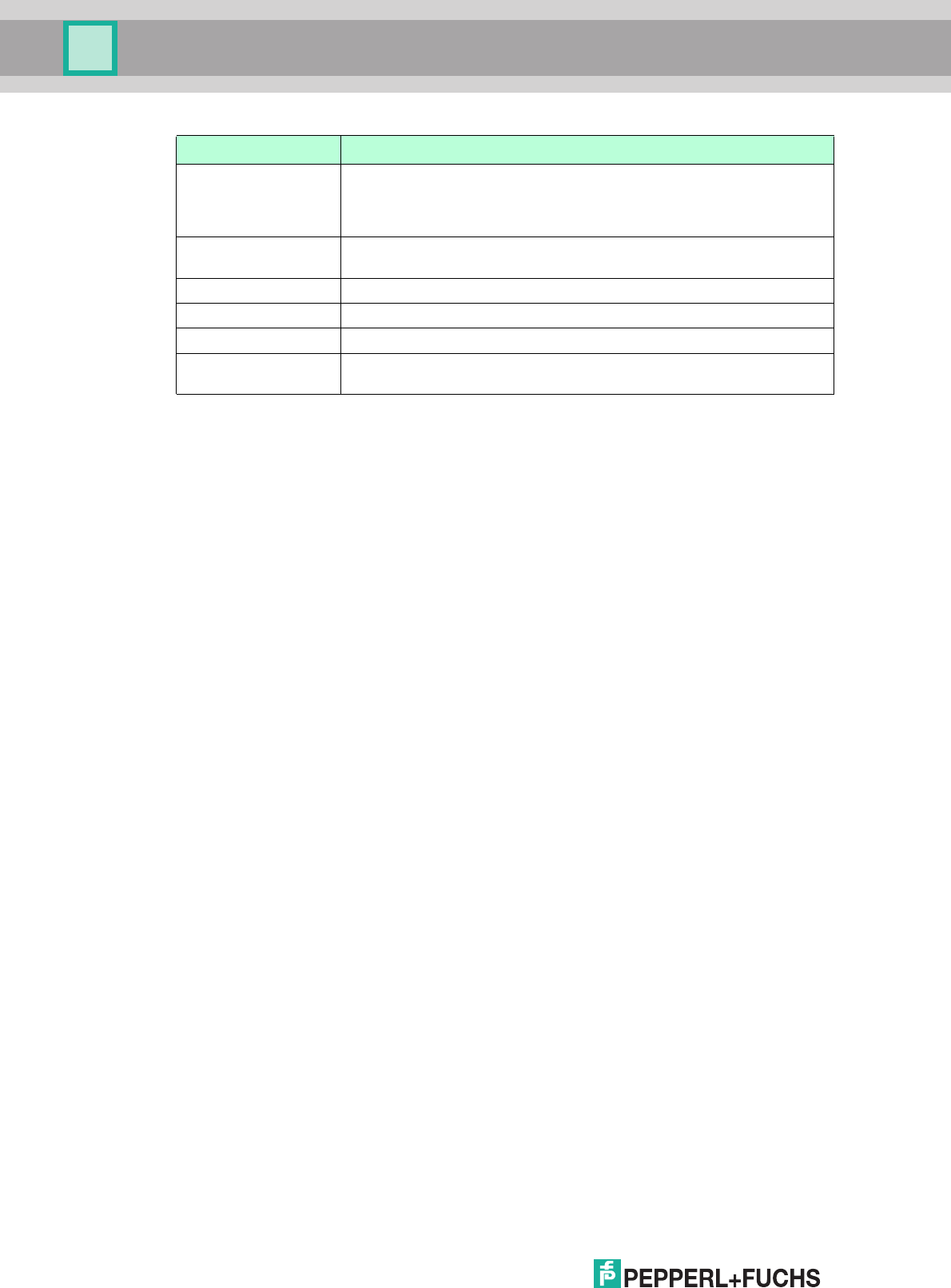
2017-12
64
IUH-F190-V1-*, IUT-F190-R4-V1*
Operation
A Singleframe protocol: there are multiple tags in the measurement
range (IUH*).
Multiframe protocol: There are multiple tags in the measurement
range that have the same UII/EPC (IUH*).
B Indicates the output of additional information (see "Output Additional
Information, "Information" IF" on page 51).
C Reserved
D Reserved
E Internal buffer overflow; execute reset.
F Indicates the end of an output in the multiframe protocol (see "Protocol
Mode QV" on page 55).
Status Description

IUH-F190-V1-*, IUT-F190-R4-V1*
Service and Maintenance
2017-12
65
7 Service and Maintenance
The device is designed and constructed to function stable over long periods of time. For this
reason, regular cleaning or maintenance is unnecessary.

2017-12
66
IUH-F190-V1-*, IUT-F190-R4-V1*
Troubleshooting
8 Troubleshooting
Problem Solution
Interference from
several read/write
heads in the direct
vicinity
■
Use the multi-plex mode of the IDENTControl control interface
■
Change the setting of the transmission channels
■
Reduce the transmission power
Status A message
■
Check whether there are multiple tags in the detection range:
Remove the tag from the detection range by placing the tag e.g. in a
sealed metal container
Repeat the read or write operation
■
Use filter commands
■
Determine whether multiple tags have the same UII/EPC
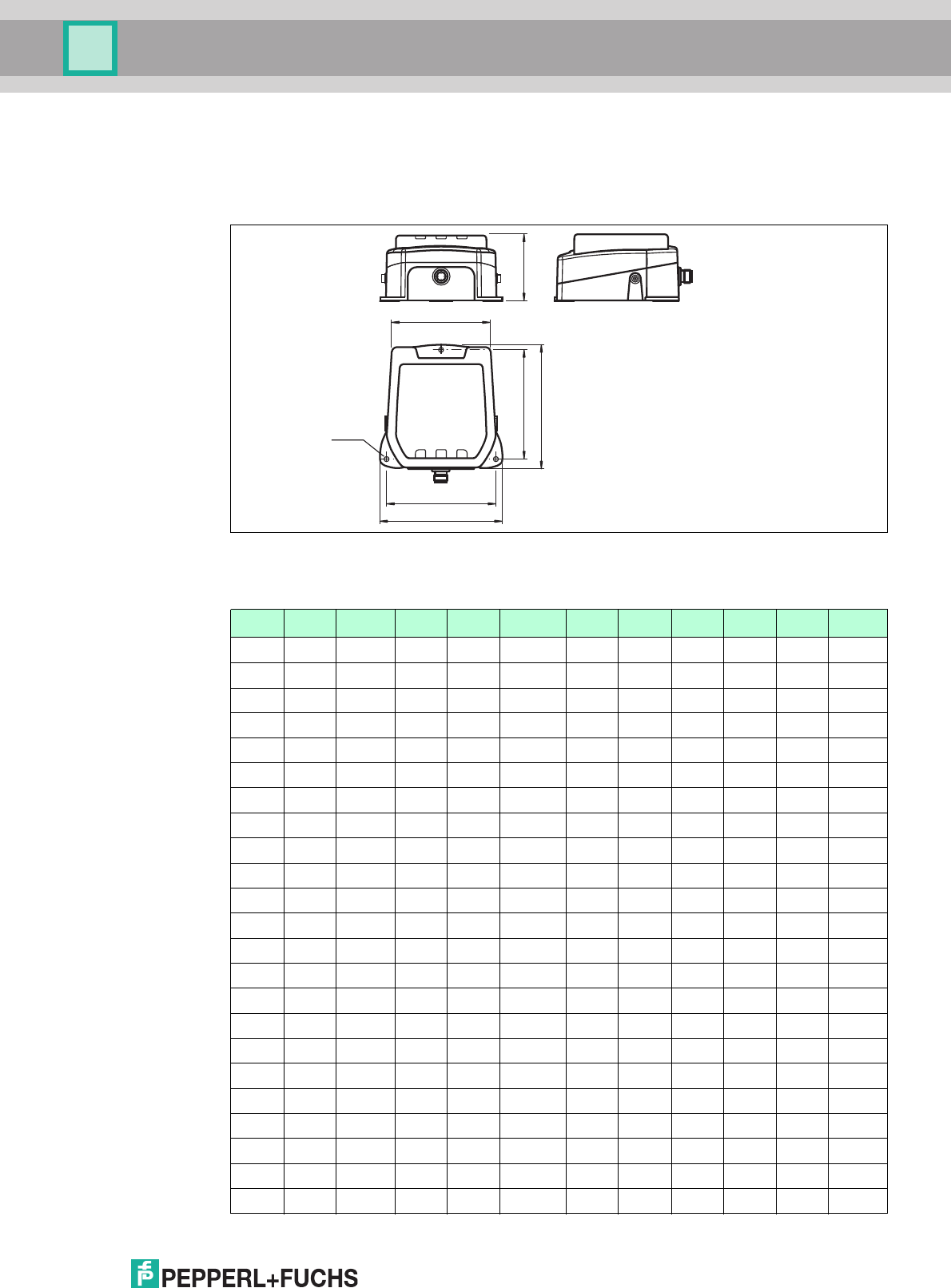
IUH-F190-V1-*, IUT-F190-R4-V1*
Appendix
2017-12
67
9 Appendix
9.1 Dimensions
Figure 9.1
9.2 ASCII Table
IUH-F190-V1-* and IUT-F190-R4-V1-*
100
ø4 (3x)
100
114
90
112
63
hex dec ASCII hex dec ASCII hex dec ASCII hex dec ASCII
00 0 NUL 20 32 Space 40 64 @ 60 96 '
01 1 SOH 21 33 ! 41 65 A 61 97 a
02 2 STX 22 34 " 42 66 B 62 98 b
03 3 ETX 23 35 # 43 67 C 63 99 c
04 4 EOT 24 36 $ 44 68 D 64 100 d
05 5 ENQ 25 37 % 45 69 E 65 101 e
06 6 ACK 26 38 & 46 70 F 66 102 f
07 7 BEL 27 39 ' 47 71 G 67 103 g
08 8 BS 28 40 ( 48 72 H 68 104 h
09 9 HT 29 41 ) 49 73 I 69 105 I
0A 10 LF 2A 42 * 4A 74 J 6A 106 j
0B 11 VT 2B 43 + 4B 75 K 6B 107 k
0C 12 FF 2C 44 , 4C 76 L 6C 108 l
0D 13 CR 2D 45 - 4D 77 M 6D 109 m
0E 14 SO 2E 46 . 4E 78 N 6E 110 n
0F 15 SI 2F 47 / 4F 79 O 6F 111 o
10 16 DLE 30 48 0 50 80 P 70 112 p
11 17 DC1 31 49 1 51 81 Q 71 113 q
12 18 DC2 32 50 2 52 82 R 72 114 r
13 19 DC3 33 51 3 53 83 S 73 115 s
14 20 DC4 34 52 4 54 84 T 74 116 t
15 21 NAK 35 53 5 55 85 U 75 117 u
16 22 SYN 36 54 6 56 86 V 76 118 v
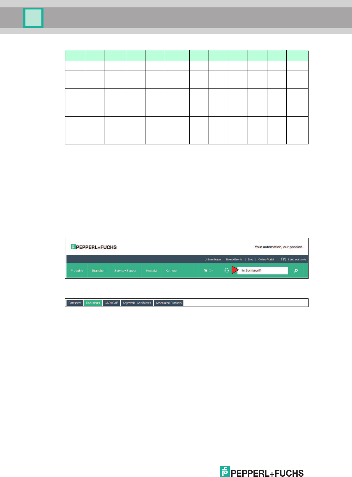
2017-12
68
IUH-F190-V1-*, IUT-F190-R4-V1*
Appendix
9.3 Detection Range
The read/write head has a typical detection range of around 1 meter; this range is determined
by the tag used and can be adjusted by selecting the transmission power. Other influencing
factors include the setup and installation of the specific application, interference from any
materials present (in particular metal), and the ambient conditions. The read and write
distances for the relevant tag, which are detailed separately, have been established in a test
laboratory under ideal conditions. For this reason, the combination of read/write head and tag
must be tested for the intended application under real conditions.
Please note the distance tables. The distance tables and additional information regarding your
product can be found at http://www.pepperl-fuchs.com. Simply enter the product name or
model number in the Search box and then click the Search key.
Select your product from the list of search results. Click on the information you require in the
product information list, e.g., Technical documents.
A list of all available documents is displayed.
17 23 ETB 37 55 7 57 87 W 77 119 w
18 24 CAN 38 56 8 58 88 X 78 120 x
19 25 EM 39 57 9 59 89 Y 79 121 y
1A 26 SUB 3A 58 : 5A 90 Z 7A 122 z
1B 27 ESC 3B 59 ; 5B 91 [ 7B 123 {
1C 28 FS 3C 60 < 5C 92 \ 7C 124 |
1D 29 GS 3D 61 = 5D 93 ] 7D 125 }
1E 30 RS 3E 62 > 5E 94 ^ 7E 126 ~
1F 31 US 3F 63 ? 5F 95 _ 7F 127 DEL
hex dec ASCII hex dec ASCII hex dec ASCII hex dec ASCII
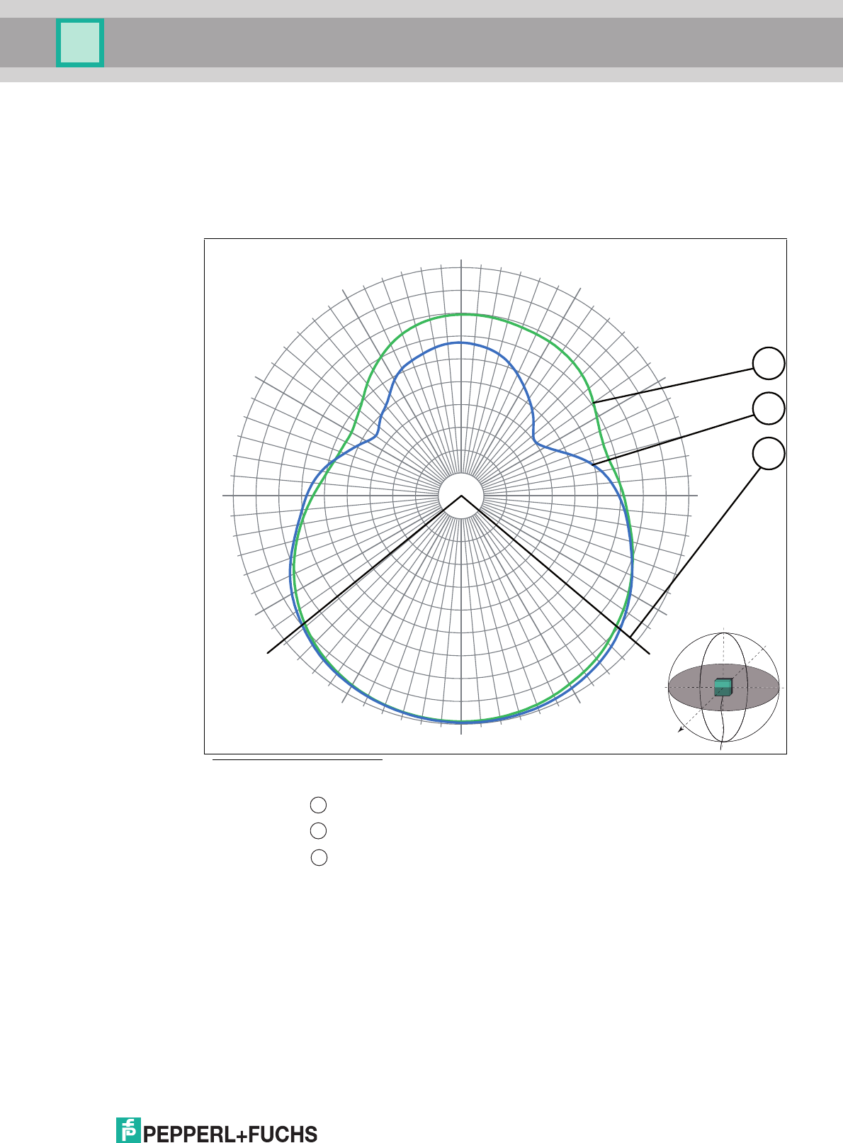
IUH-F190-V1-*, IUT-F190-R4-V1*
Appendix
2017-12
69
Antenna Diagram
The antenna diagrams show the electric field strength in the far field depending on the
direction. The front of the read/write head points towards 0°.
IUH-F190-V1-FR2* and IUT-F190-R4-V1-FR2*
Figure 9.2 - Horizontal polarization
- Vertical polarization
- Full width at half maximum
Horizontal Cut
1
1.Read/write head points towards 0°
-30 dB
-27 dB
-24 dB
-21 dB
-18 dB
-15 dB
-12 dB
-9 dB
-6 dB
-3 dB
0 dB
-180
-150
-120
-90
-60
-30
0
30
60
90
120
150
3
1
2
1
2
3
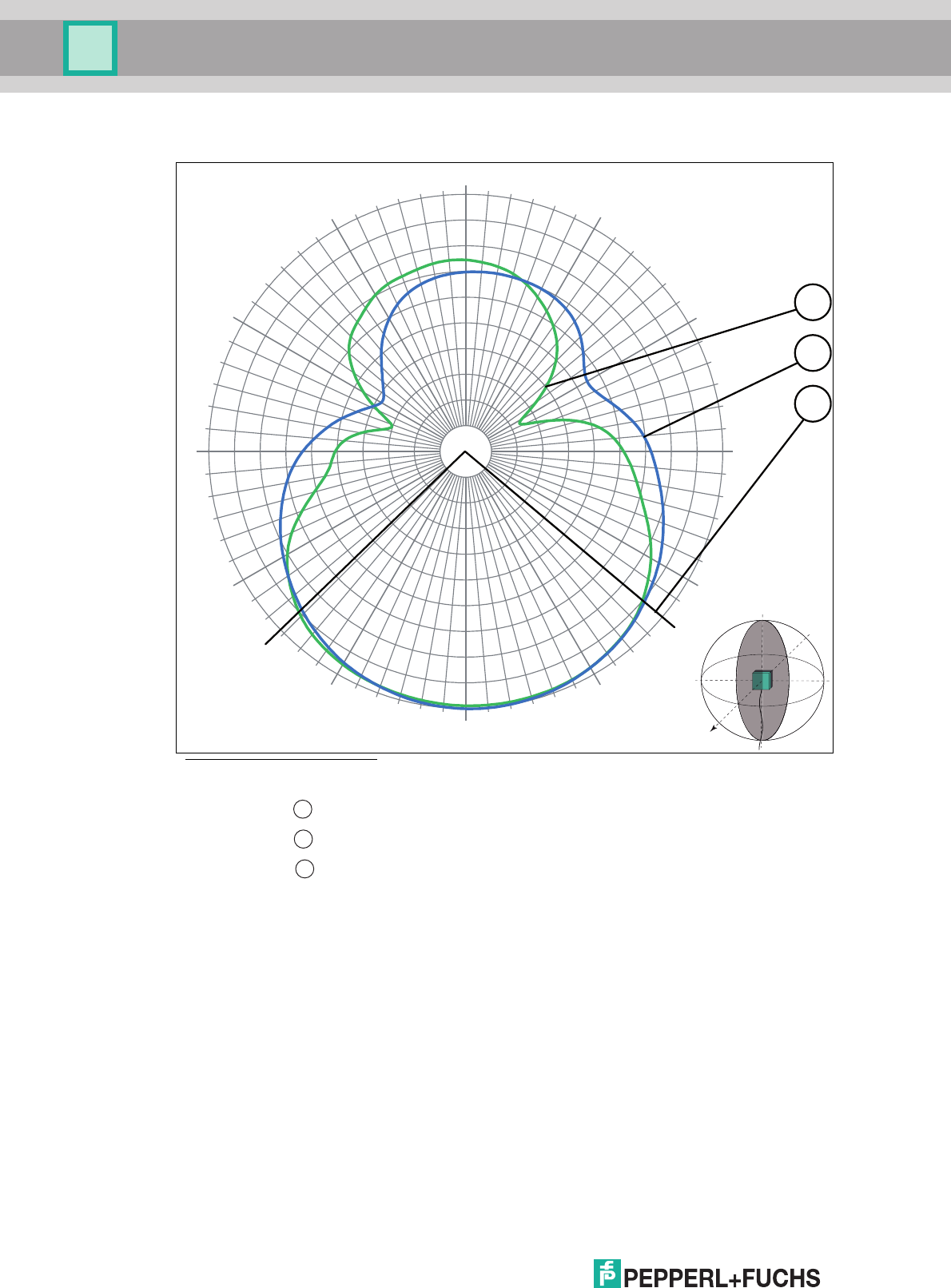
2017-12
70
IUH-F190-V1-*, IUT-F190-R4-V1*
Appendix
Figure 9.3 - Horizontal polarization
- Vertical polarization
- Full width at half maximum
Vertical Cut
1
1.Read/write head points towards 0°
-180
-150
-120
-90
-60
-30
0
30
60
90
120
150
-30 dB
-27 dB
-24 dB
-21 dB
-18 dB
-15 dB
-12 dB
-9 dB
-6 dB
-3 dB
0 dB
3
1
2
1
2
3

IUH-F190-V1-*, IUT-F190-R4-V1*
Appendix
2017-12
71

Subject to modifications
Copyright PEPPERL+FUCHS • Printed in Germany
www.pepperl-fuchs.com
FACTORY AUTOMATION –
SENSING YOUR NEEDS
Worldwide Headquarters
Pepperl+Fuchs GmbH
68307 Mannheim · Germany
Tel. +49 621 776-0
E-mail: info@de.pepperl-fuchs.com
USA Headquarters
Pepperl+Fuchs Inc.
Twinsburg, Ohio 44087 · USA
Tel. +1 330 4253555
E-mail: sales@us.pepperl-fuchs.com
Asia Pacific Headquarters
Pepperl+Fuchs Pte Ltd.
Company Registration No. 199003130E
Singapore 139942
Tel. +65 67799091
E-mail: sales@sg.pepperl-fuchs.com
/ DOCT-2945K
12/2017