Pepperl Fuchs MVI Cordless, single voltage identification system User Manual Manual
Pepperl + Fuchs Inc Cordless, single voltage identification system Manual
UserManual.wiki
>
Pepperl Fuchs
>
MVI User Manual
>
Manual
Contents
1.
Manual
2.
Appendix
Manual
Navigation menu
Upload a User Manual
Namespaces
Wiki Guide
HTML
PDF
Info
Views
User Manual
Discussion / Help
Navigation

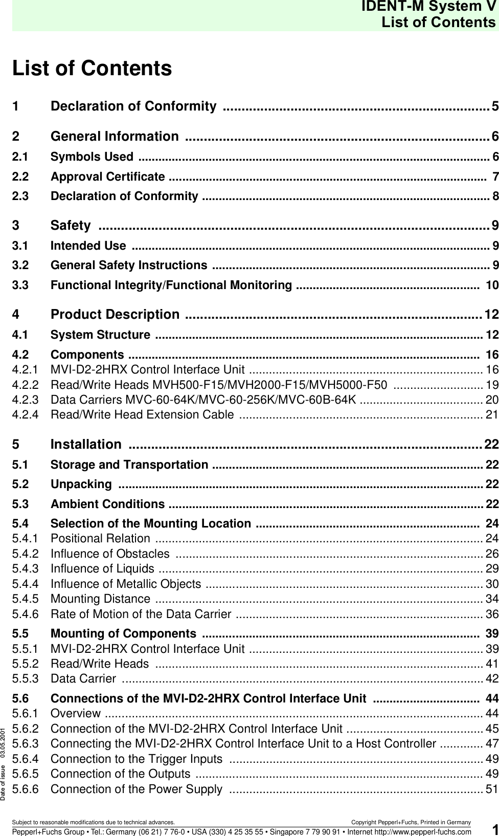
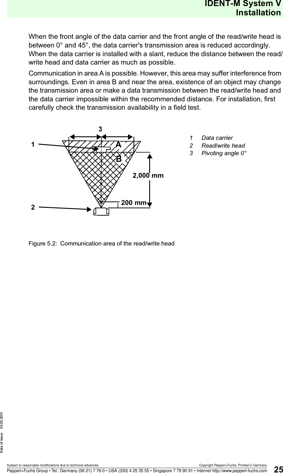
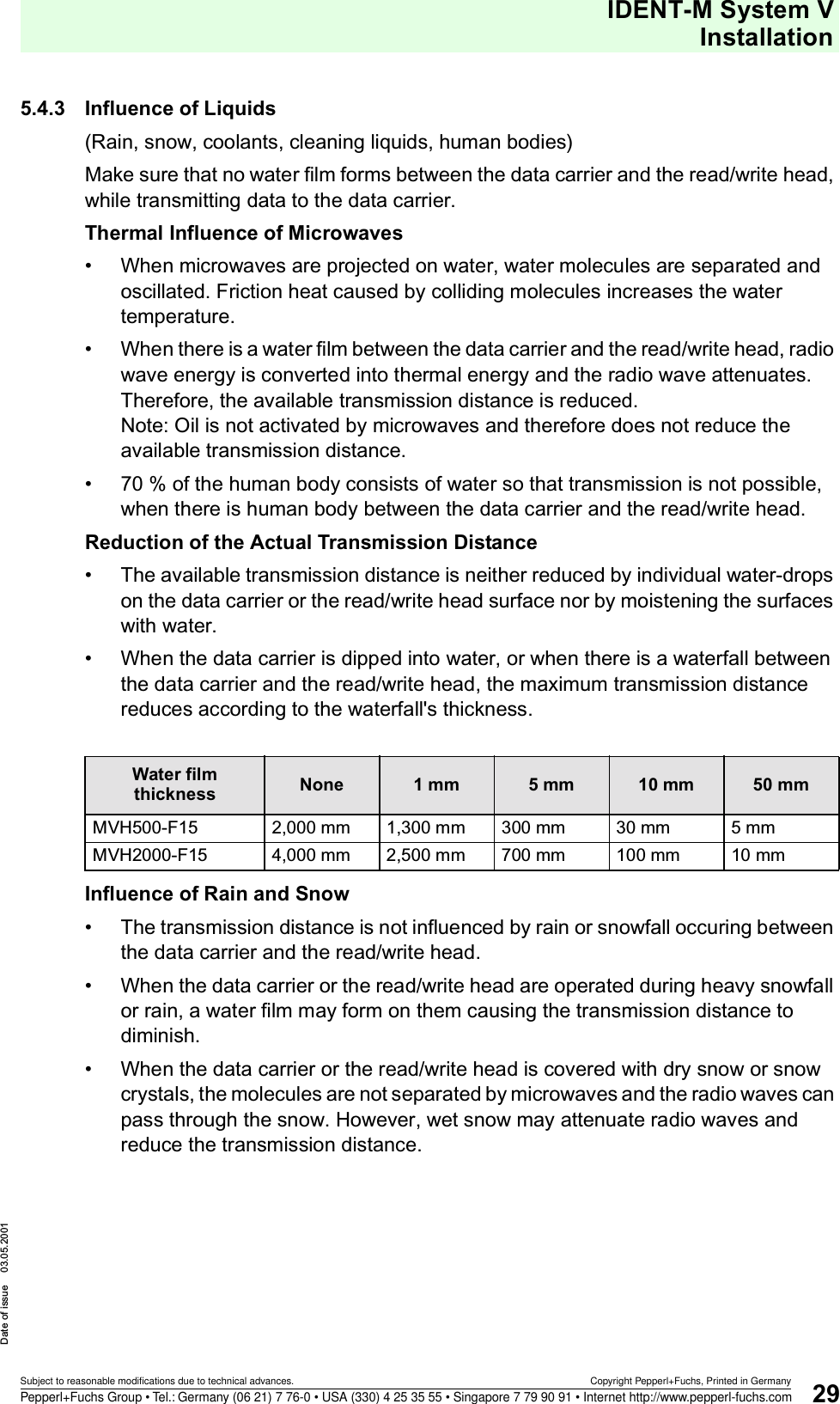
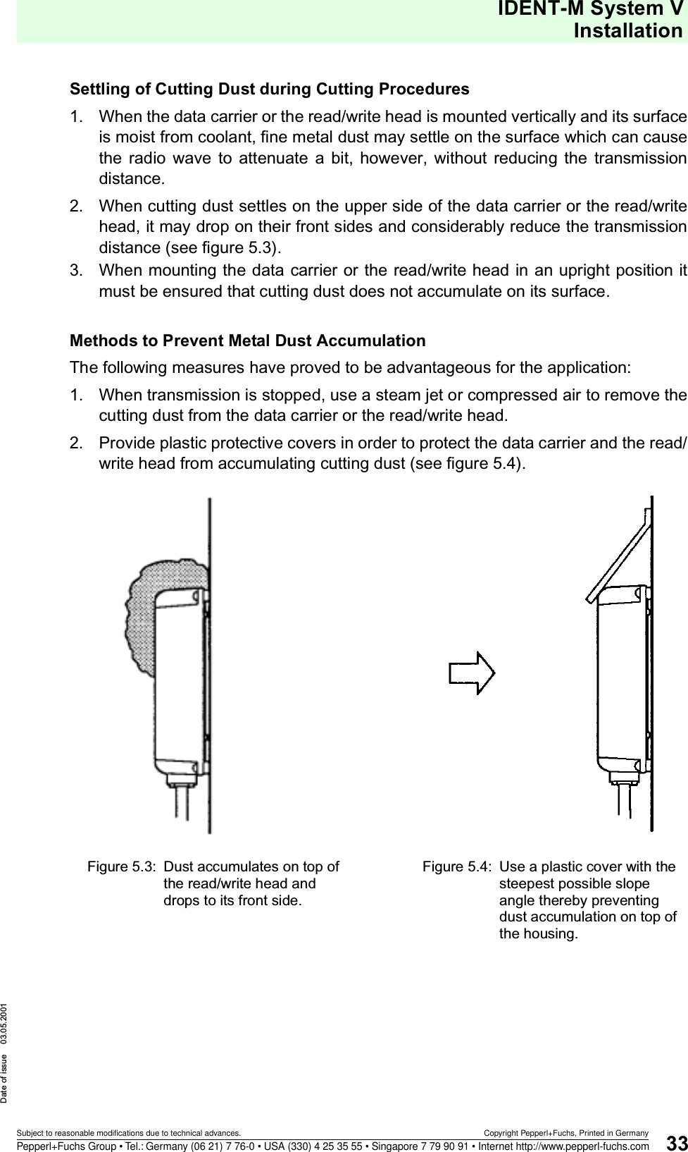
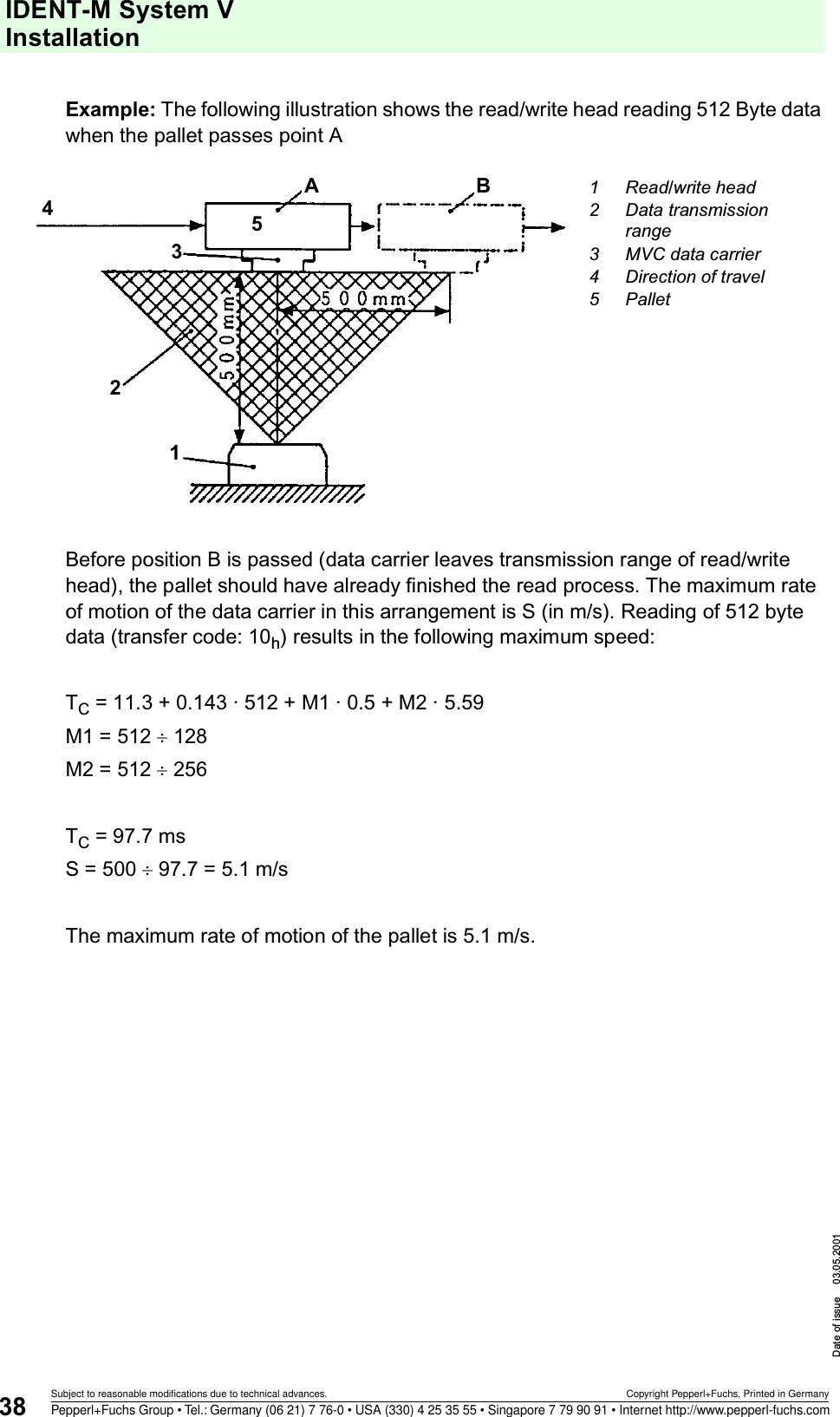
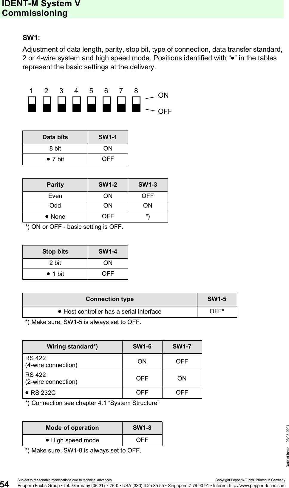
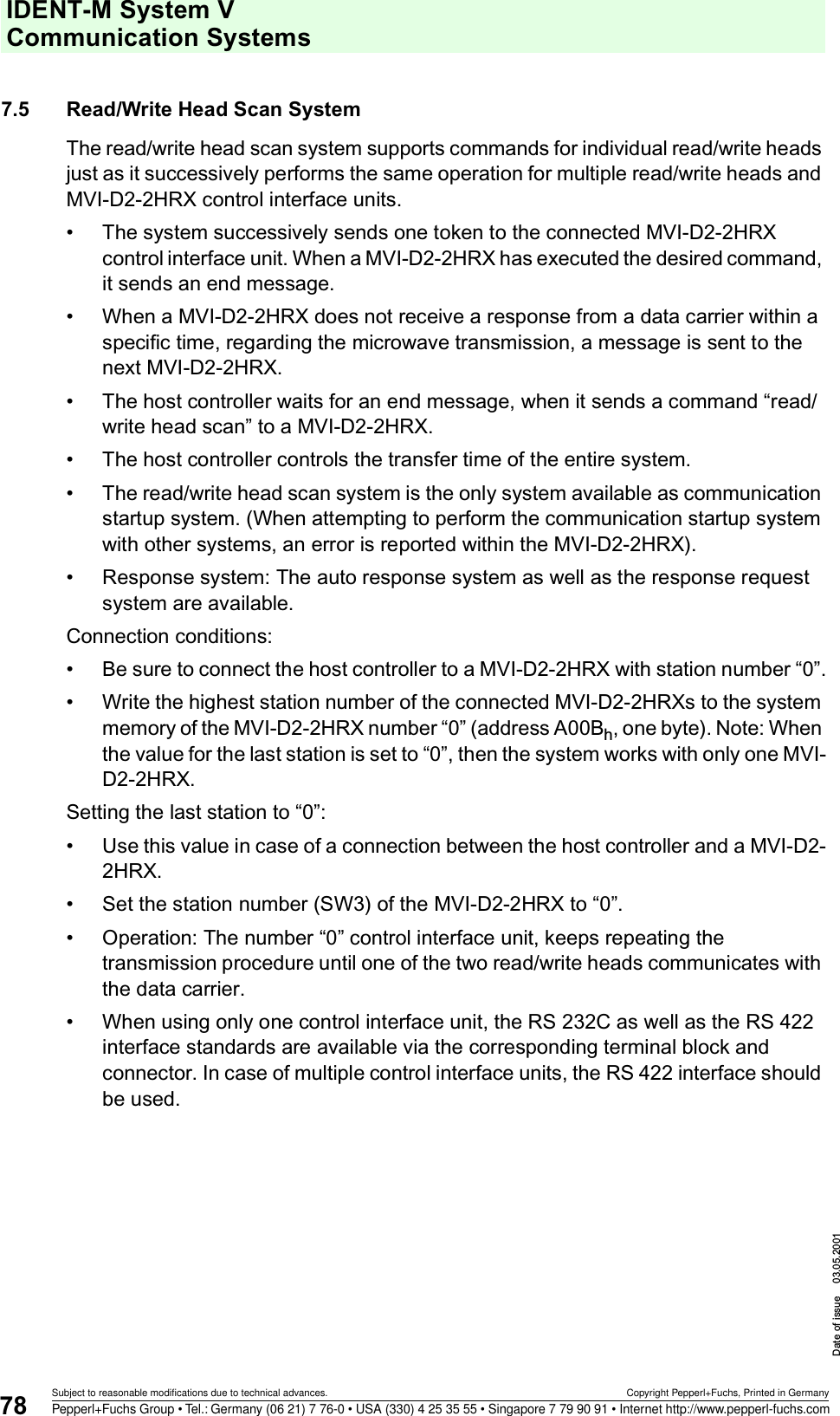
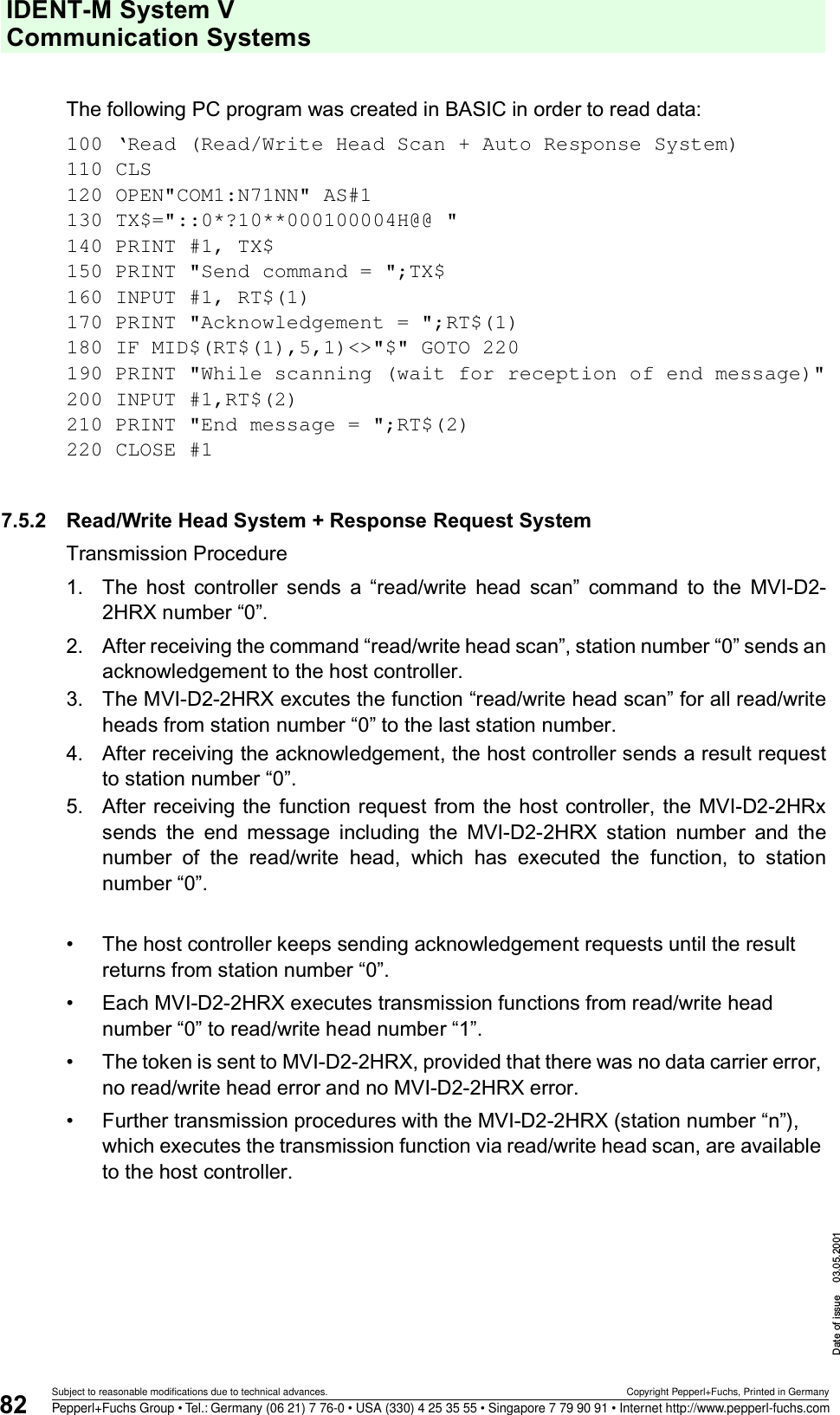
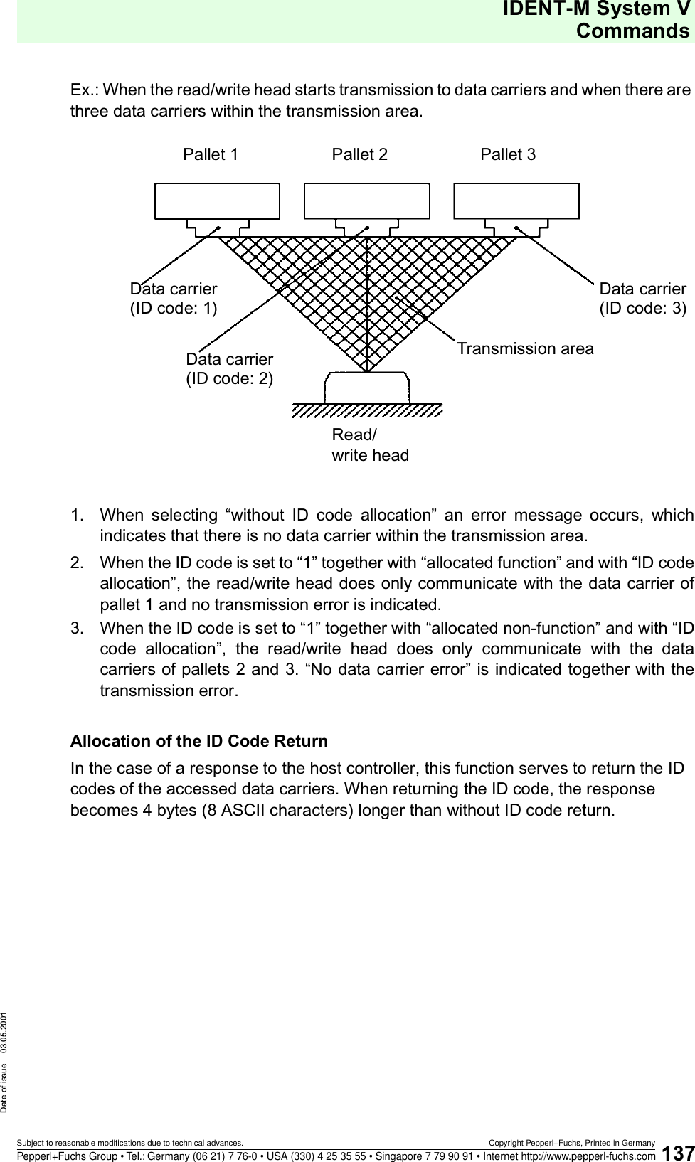
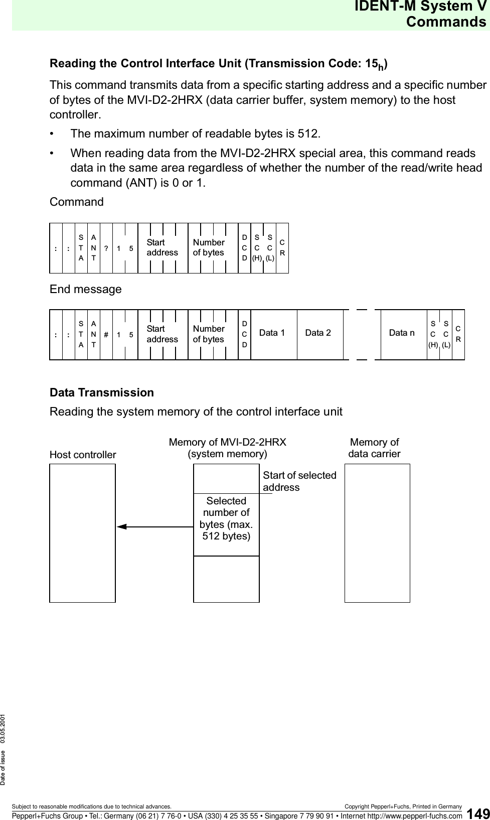
![IDENT-M System V InstallationDate of issue 03.05.200136Subject to reasonable modifications due to technical advances. Copyright Pepperl+Fuchs, Printed in GermanyPepperl+Fuchs Group • Tel.: Germany (06 21) 7 76-0 • USA (330) 4 25 35 55 • Singapore 7 79 90 91 • Internet http://www.pepperl-fuchs.comWhen the distance between neighbouring read/write heads is short, the data carrier may receive radio waves from the neighbouring read/write head.1. Perform the transmission in the “ID-code assignment” mode2. Install a metal plate in order to screen the neighbouring data carriers from radiowaves.5.4.6 Rate of Motion of the Data CarrierWhile moving, the data carrier can transmit data by means of the read/write head. However, its rate of motion is limited during the transmission process. The following maximum speed should be observed:Maximum permissible speed:1 Data carrier2 Read/write head3 Distance between neighbouring data carriersS [m/s]: Maximum permissible speed of the data carrier during the transmission process.W [mm]: Width of the transmission range, within which the data carrier moves during the data transmission to the read/write head.TC [ms]: Transfer time between read/write head and data carrier (see table on page 37). 1123WTCS =](https://usermanual.wiki/Pepperl-Fuchs/MVI.Manual/User-Guide-227994-Page-38.png)
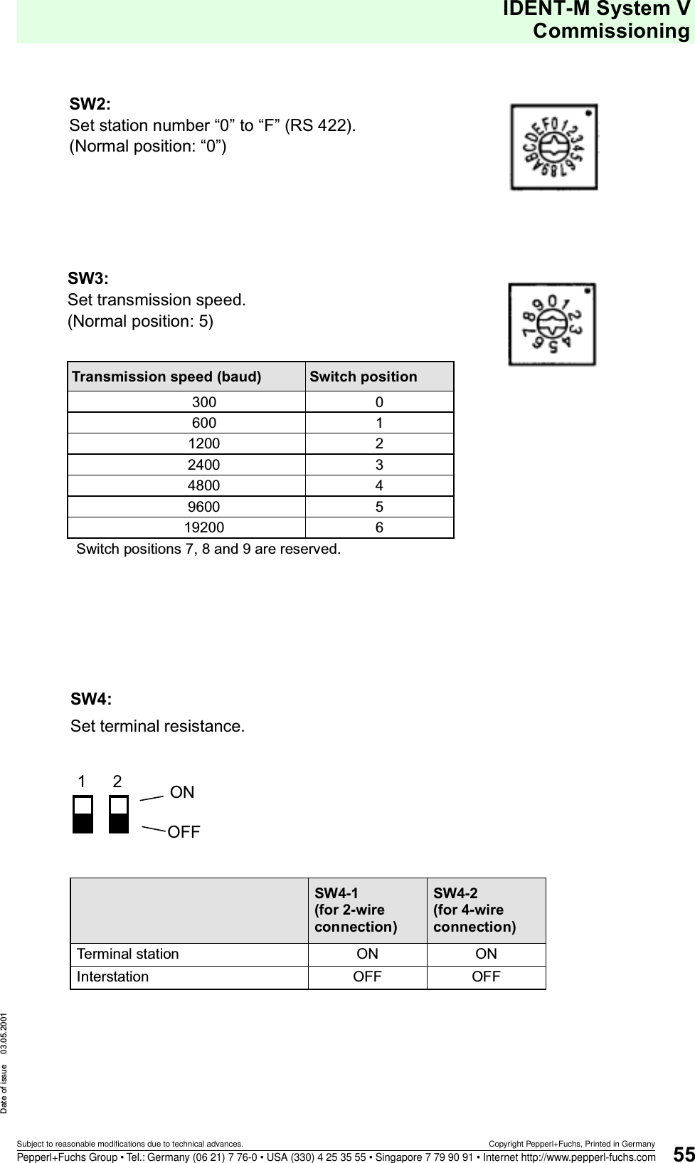
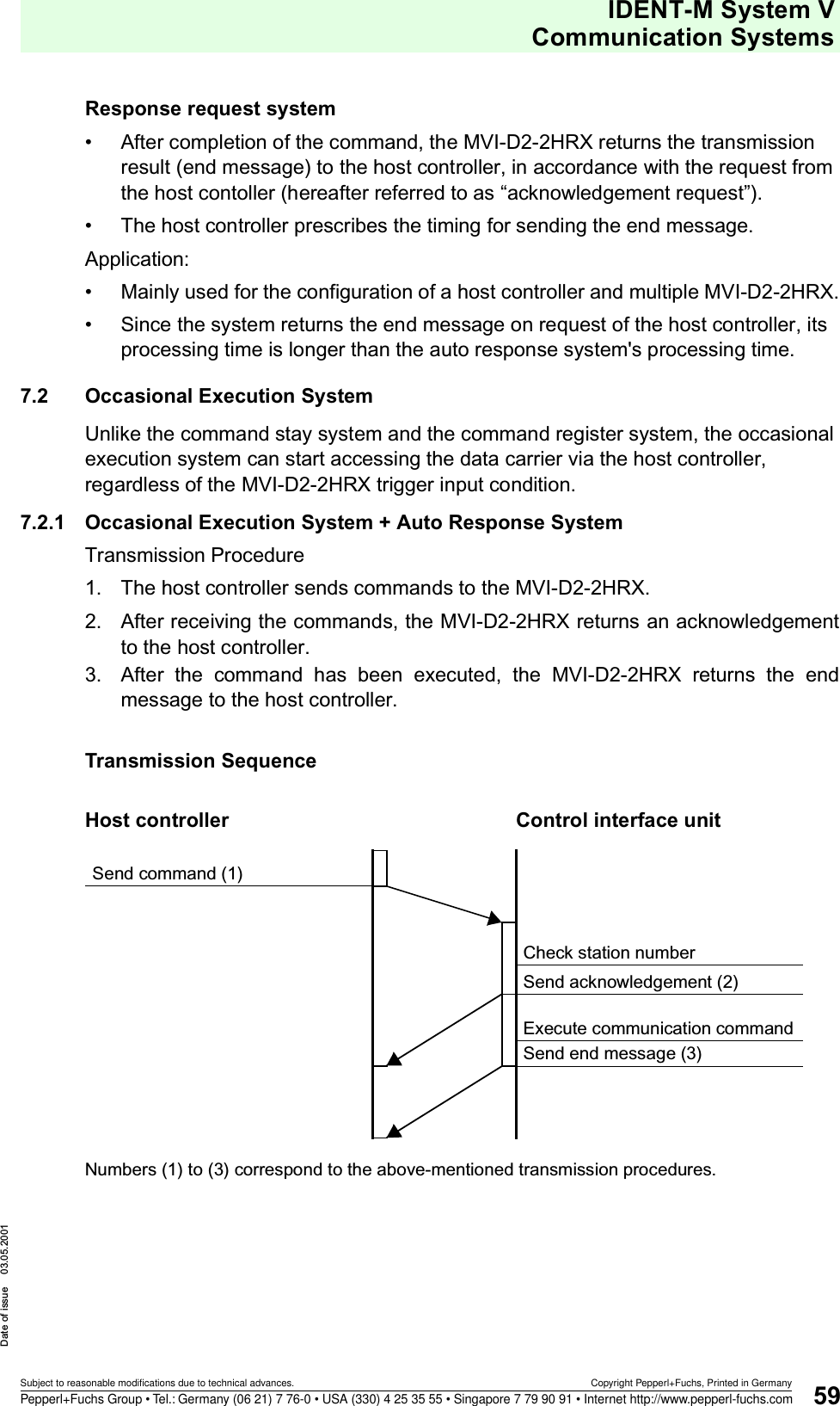
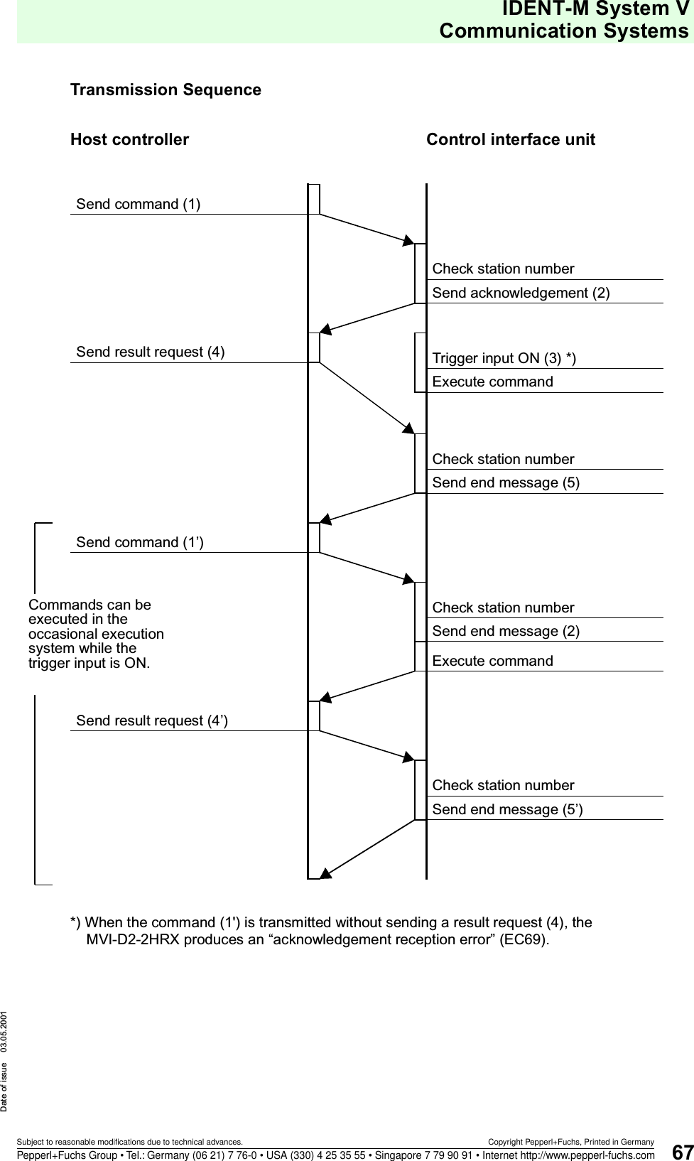
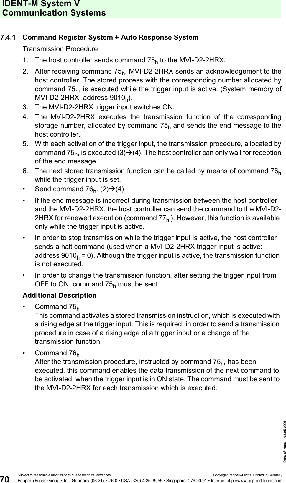
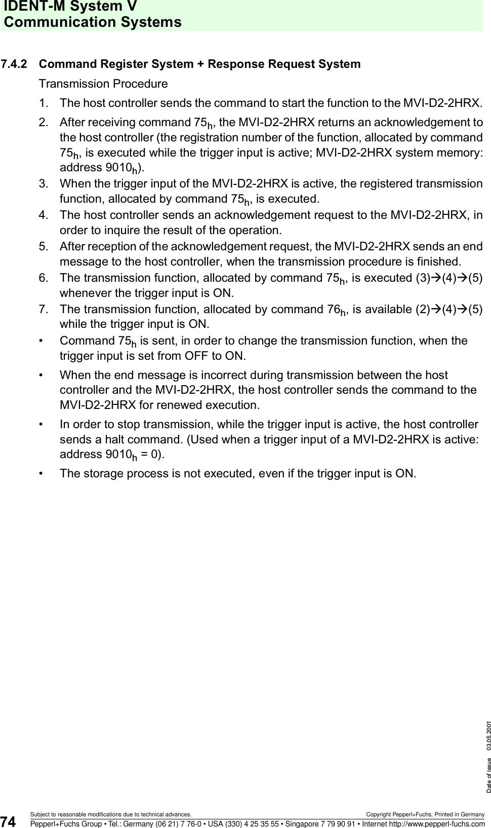
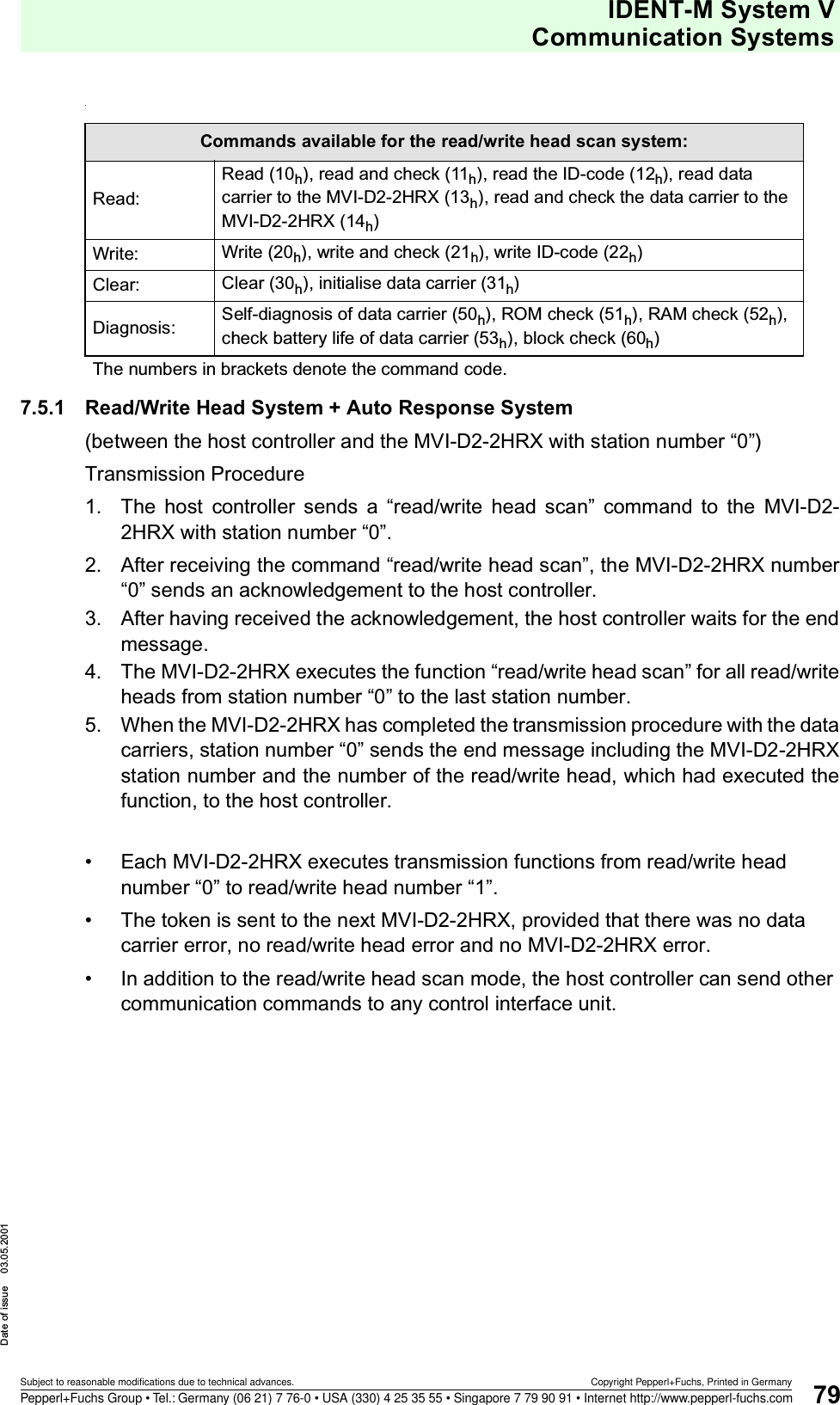
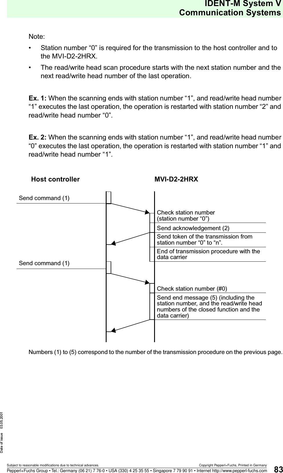
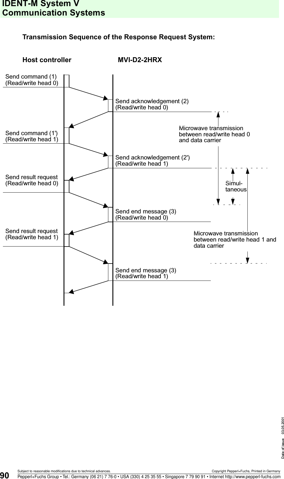
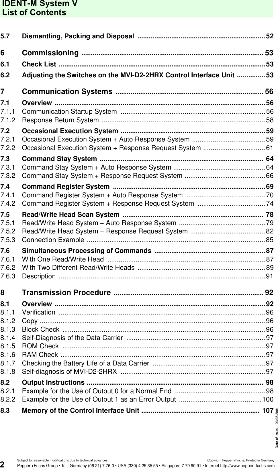
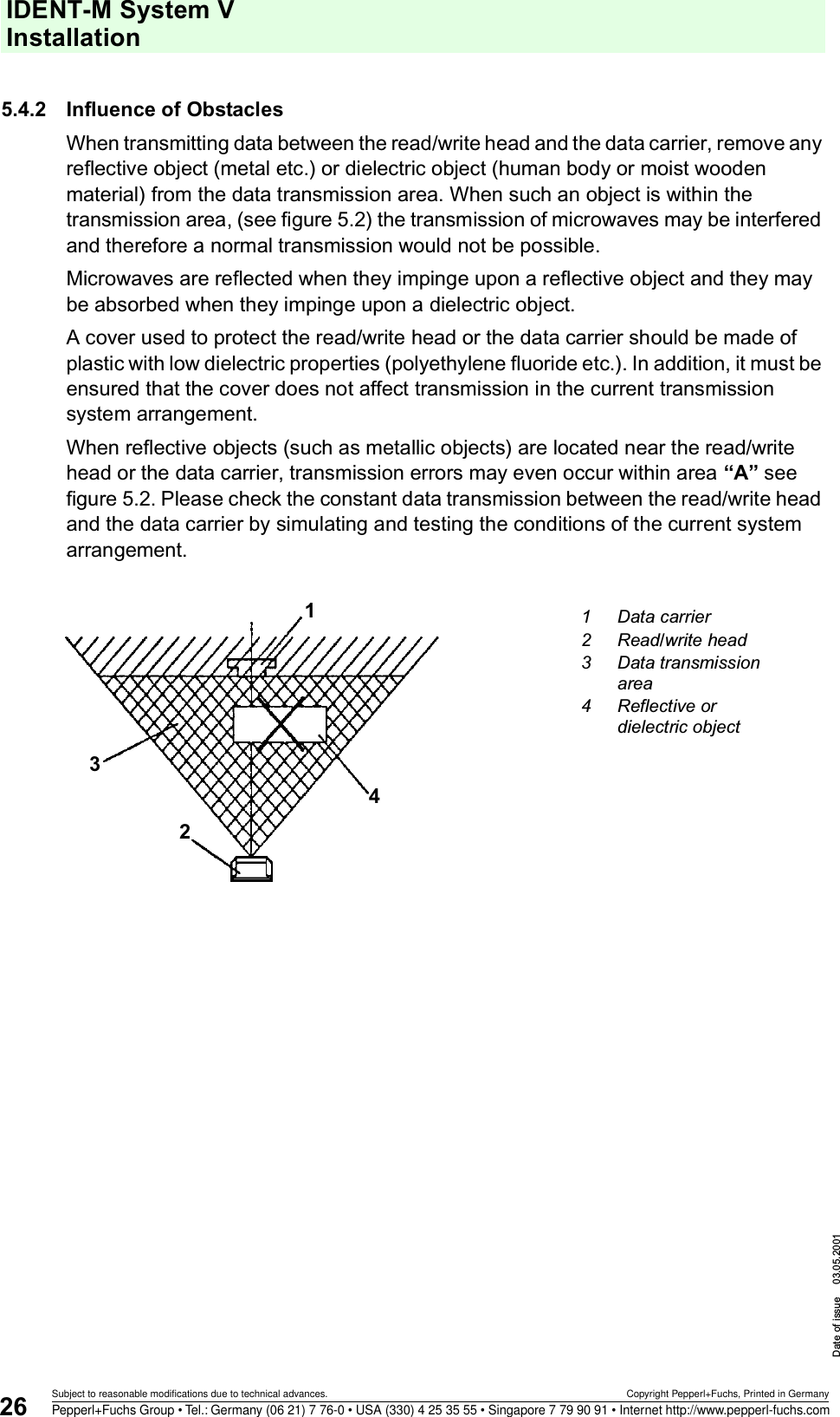
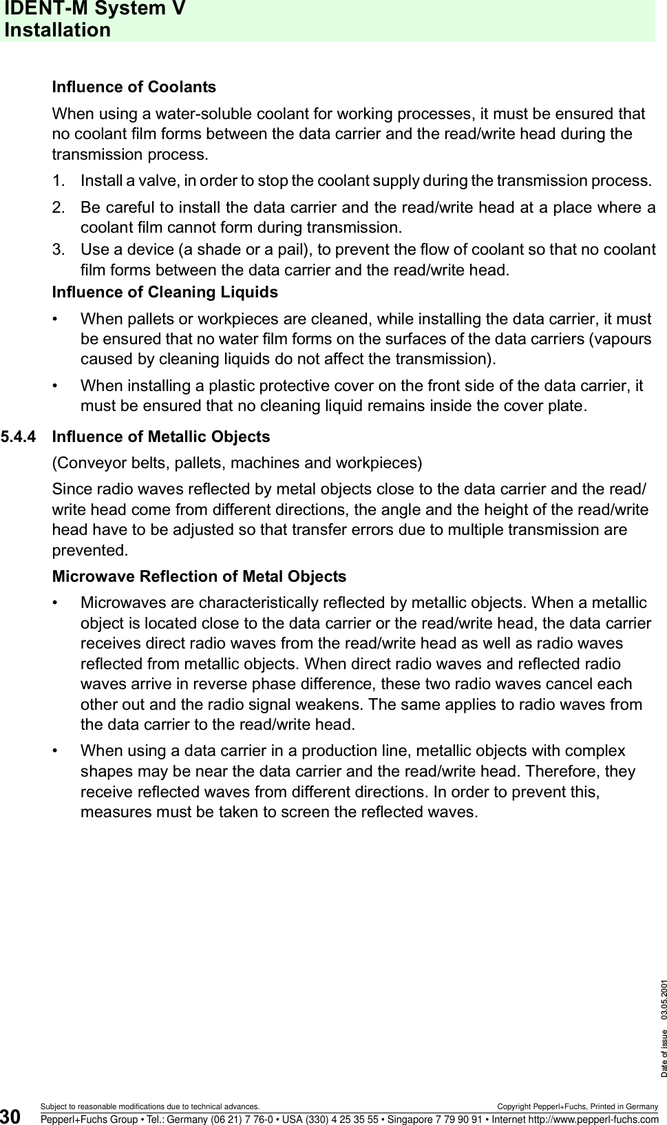
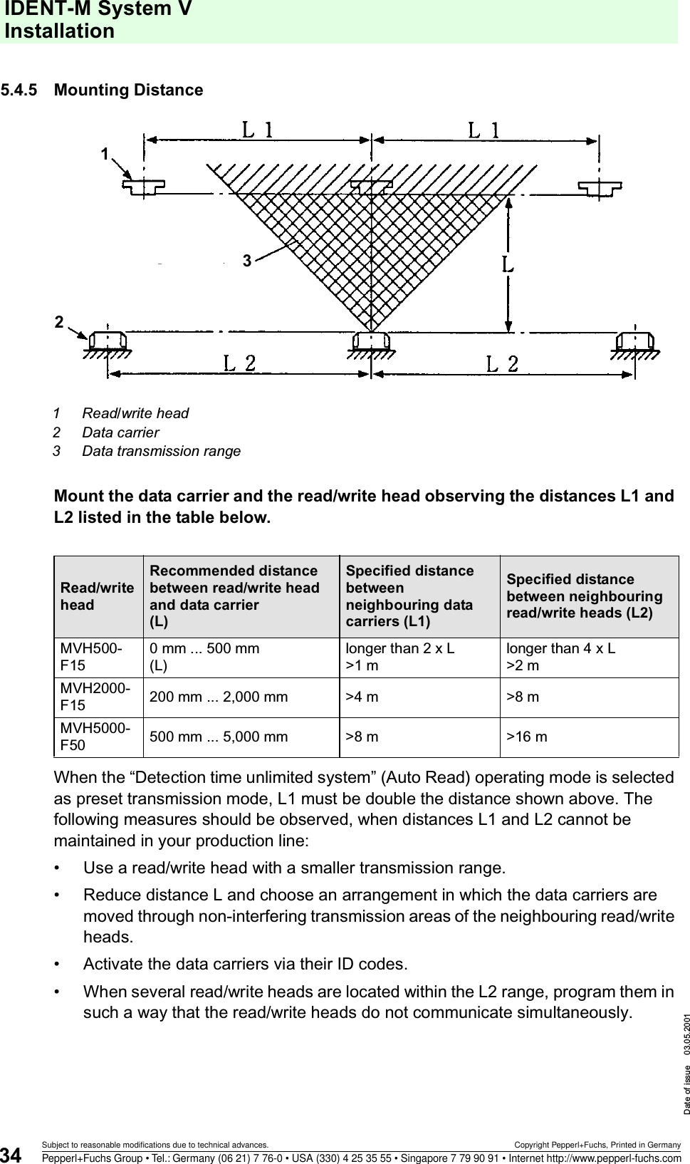
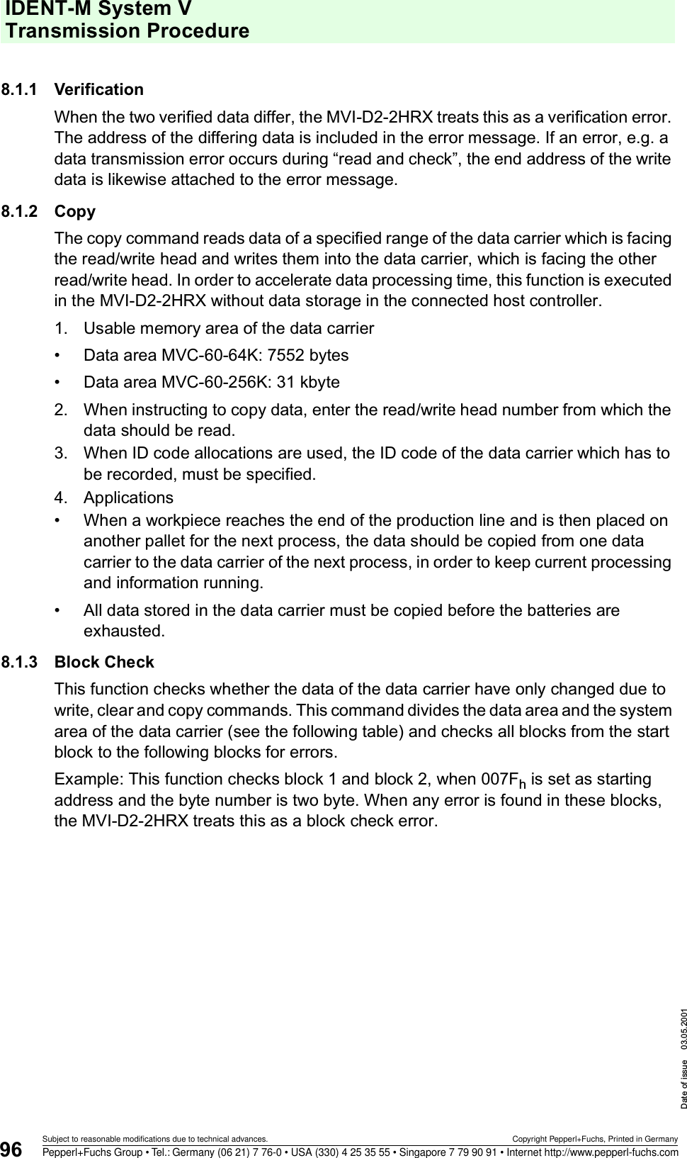
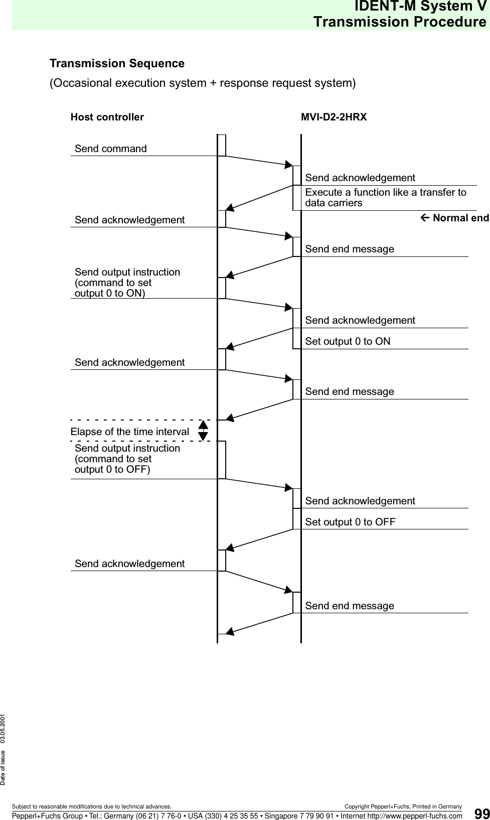
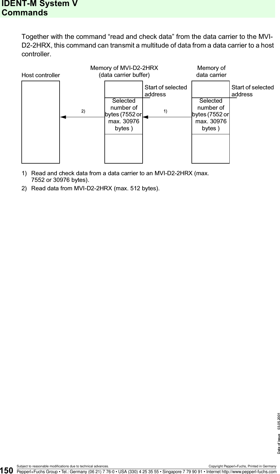
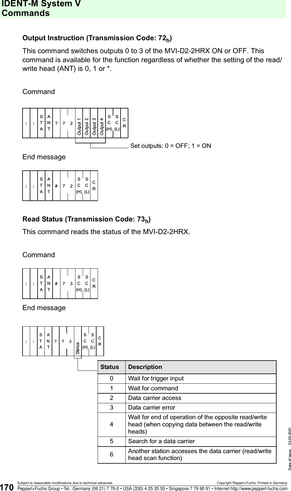
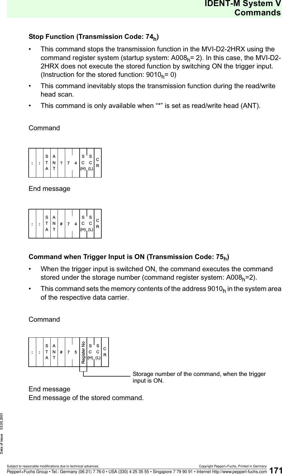
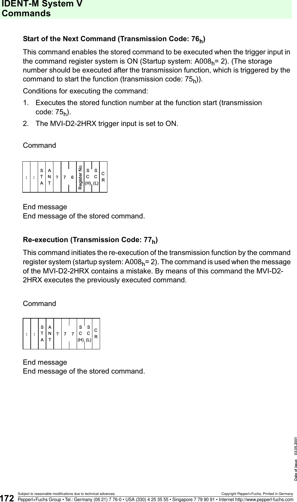
![IDENT-M System V Transmission ProcedureDate of issue 03.05.200194Subject to reasonable modifications due to technical advances. Copyright Pepperl+Fuchs, Printed in GermanyPepperl+Fuchs Group • Tel.: Germany (06 21) 7 76-0 • USA (330) 4 25 35 55 • Singapore 7 79 90 91 • Internet http://www.pepperl-fuchs.comDiagnosticSelf-diagnosis of data carriers 5 0 - P Diagnosis of ROM, RAM and battery life of data carrier.ROM check 5 1 - P Diagnosis of ROM in data carrierRAM check 5 2 - P Diagnosis of RAM in data carrier (area adjustable) Check battery life of data carrier5 3 - P Diagnosis of battery life of data carrier (checks battery voltage and service life).Self-diagnosis of MVI-D2-2HRX5 5 - C Diagnosis of ROM, RAM and battery life of MVI-D2-2HRXBlock check 6 0 - PCheck whether the data stored on the data carrier is correct, by using the block check code.OtherReset 7 0 - C• Stop the currently executed transmission procedure. • Reset error state of MVI-D2-2HRX.Request command response7 1 - CIf the response request system is applied, an acknowledgement request is transmitted to the MVI-D2-2HRX.Set outputs 7 2 - C Switch ON or OFF outputs 0 ... 3.Read status 7 3 - C Read MVI-D2-2HRX status.Stop command 7 4 - C• Instruction to stop transmission function stored in the MVI-D2-2HRX using the command register system.• Instruction to stop the read/write head scan function.Calling a registered command7 5 - C[Command register system] Instruction to start the stored command, when the trigger input is set to ON (allocate storage number likewise).Calling the registered command7 6 - C[Command register system] Instruction to start the function after ending the function triggered by the next command 75h . Simultaneous execution of functions is possible. (Operating status: Trigger input remains active.) Repeat command 7 7 - C[Command register system] The host controller requests repeated execution of the previous command (e.g.: faulty transmission of end message).Transmission procedureCommand code (Hex.) Data transm. direction Classifi-cation1) Description1) Shows the classification of the transmission procedure. Commands identified by the letter Paccess the data carriers. Commands identified by the letter C access the MVI-D2-2HRX.](https://usermanual.wiki/Pepperl-Fuchs/MVI.Manual/User-Guide-227994-Page-96.png)
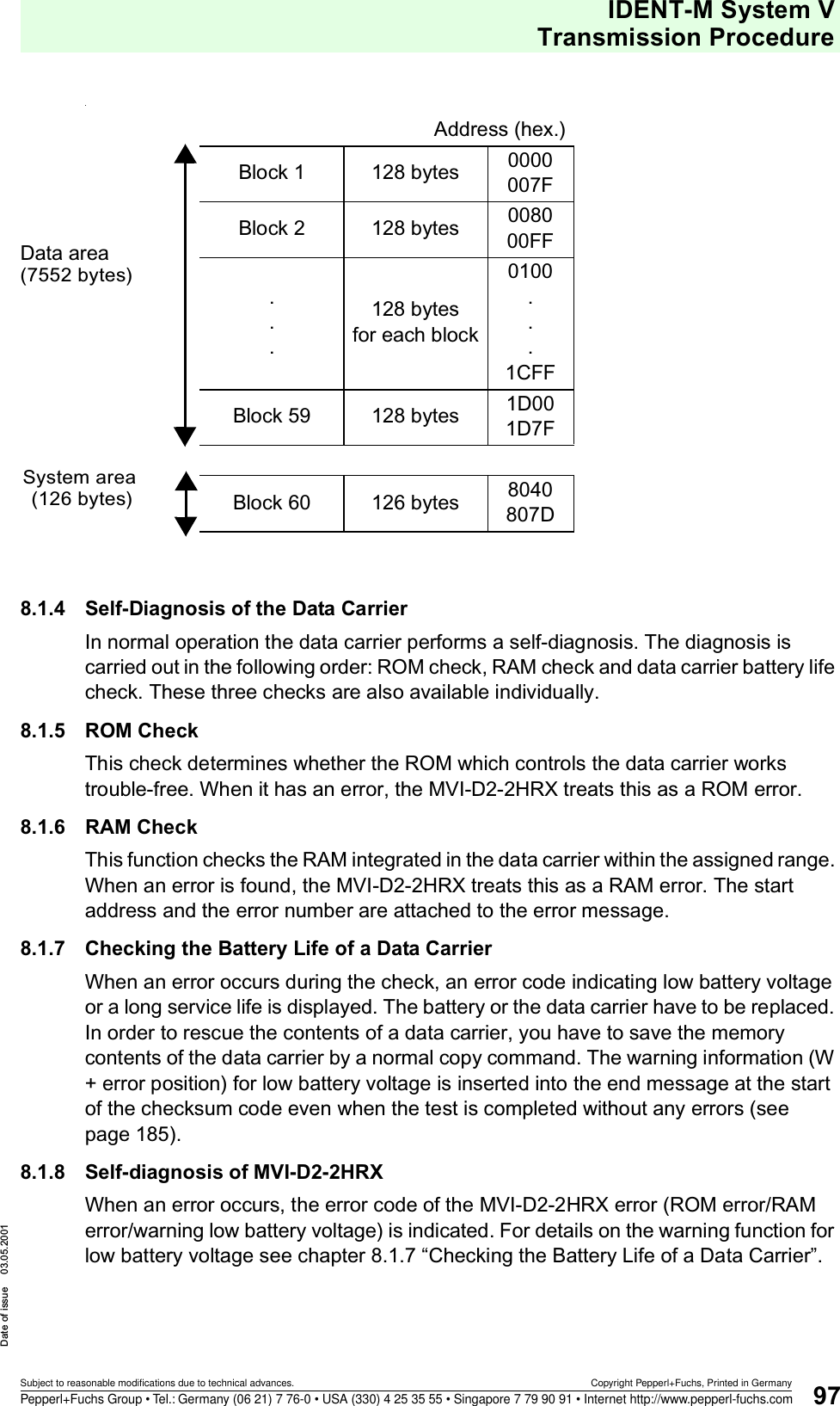
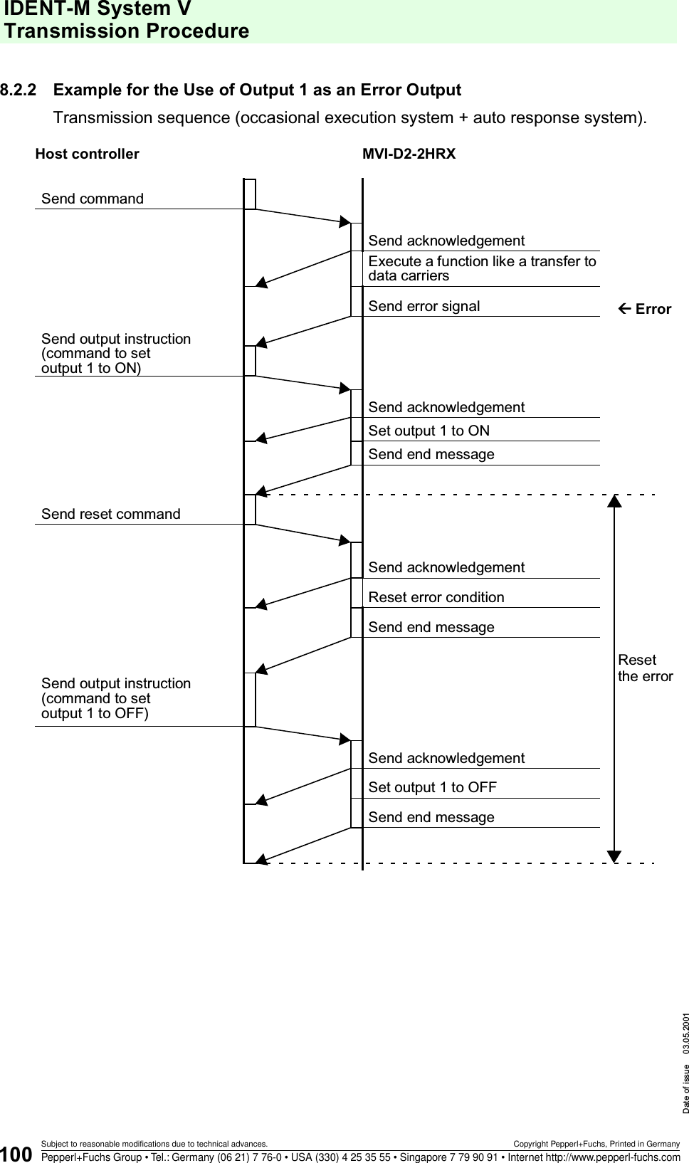
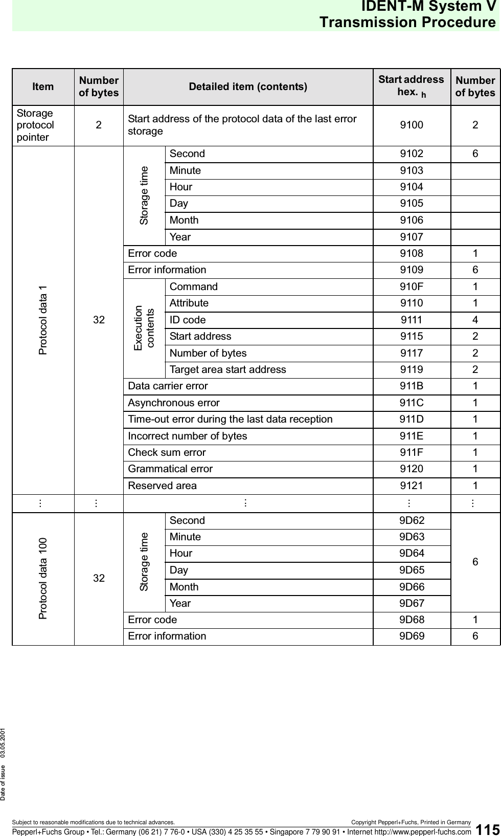
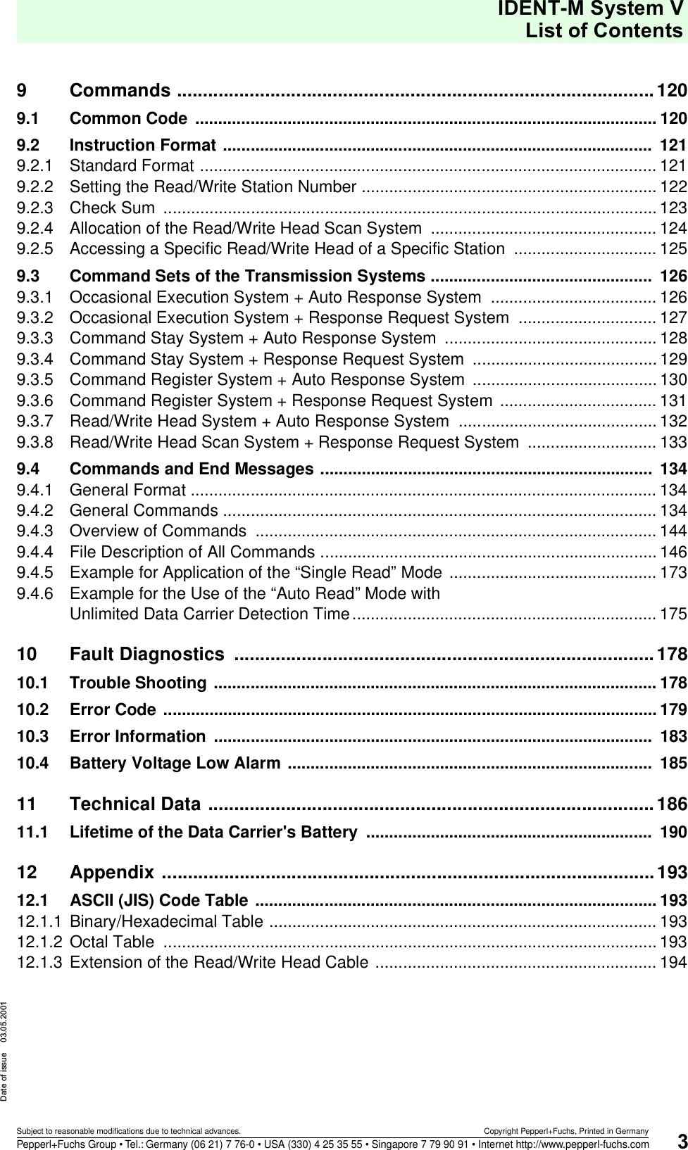
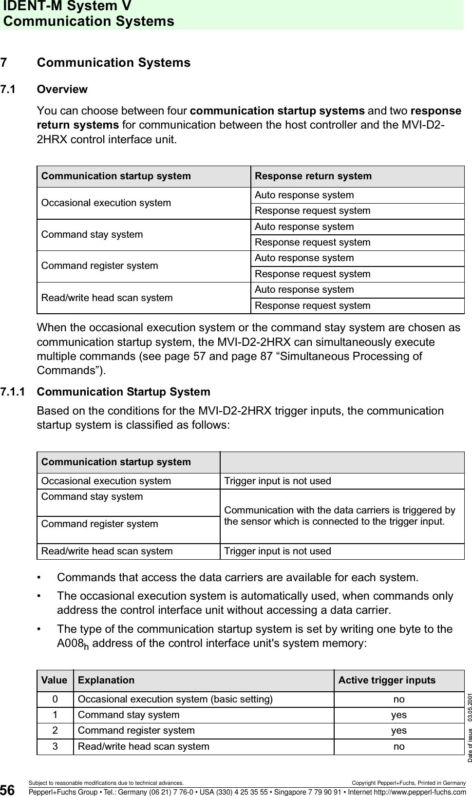
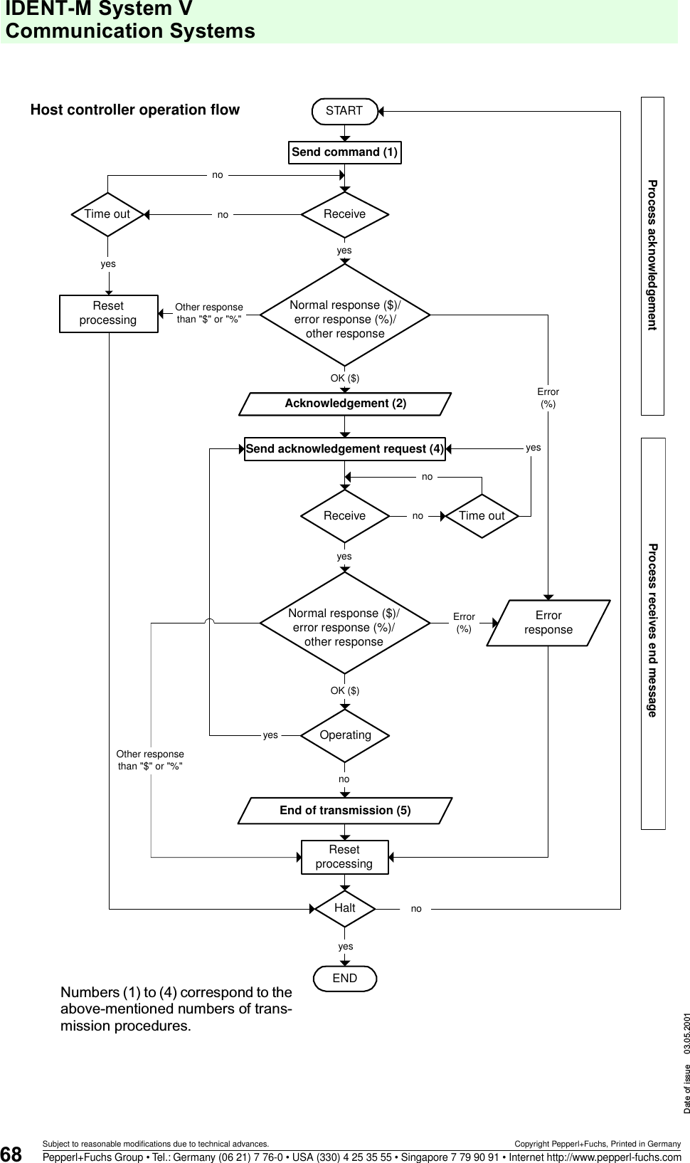
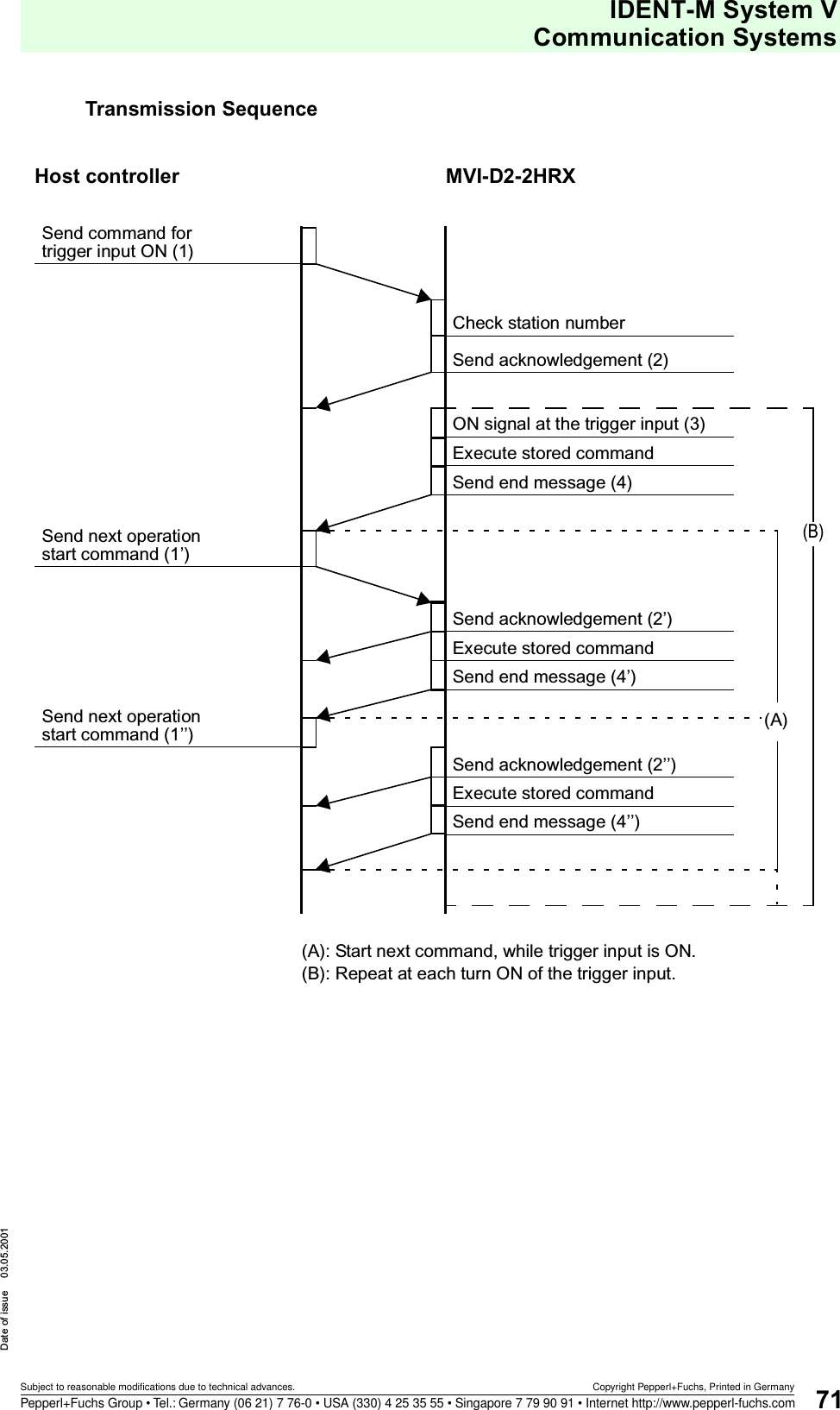
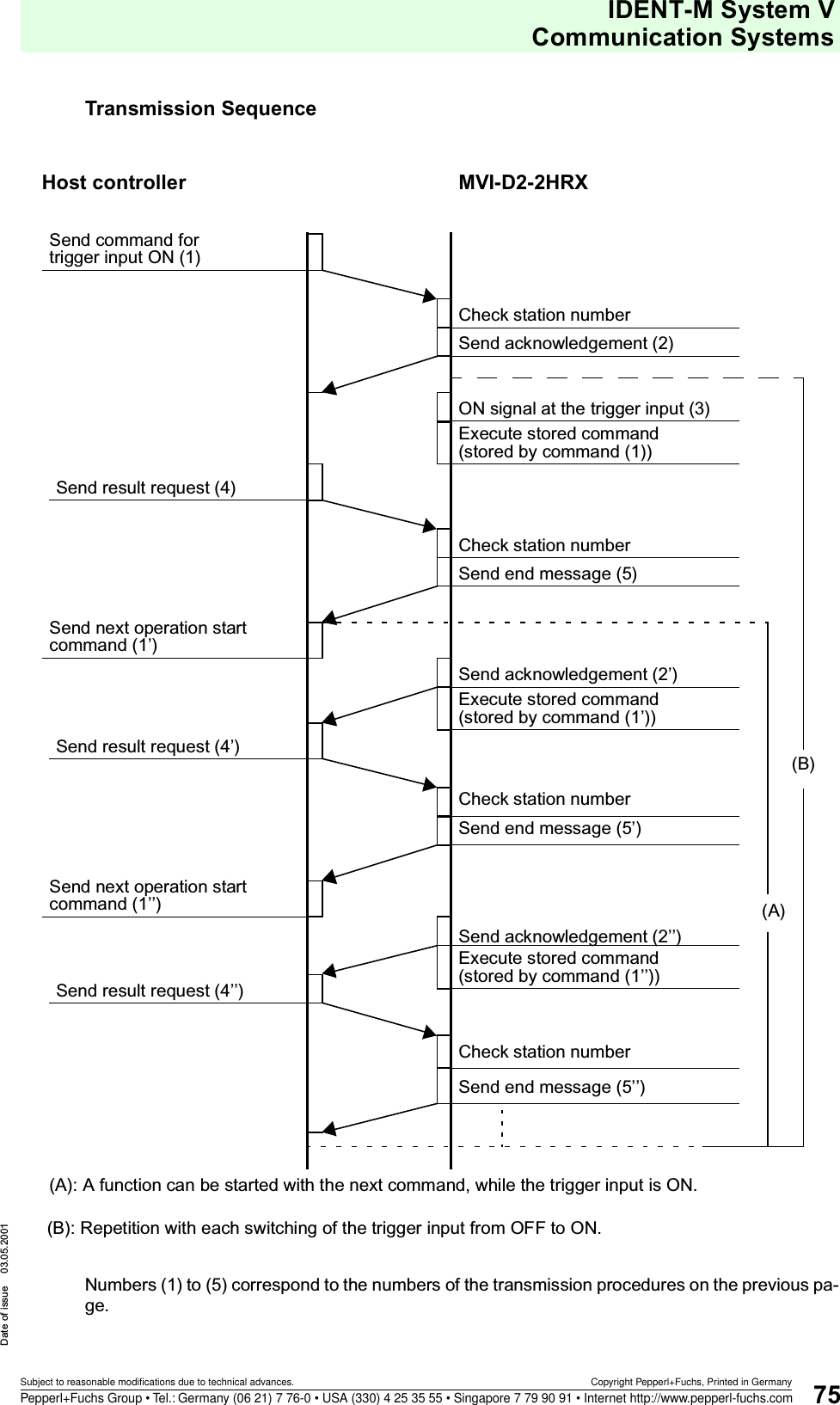
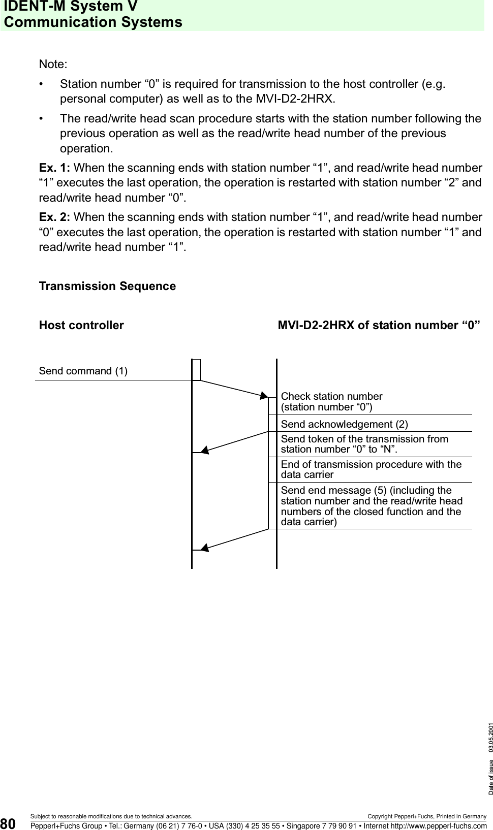
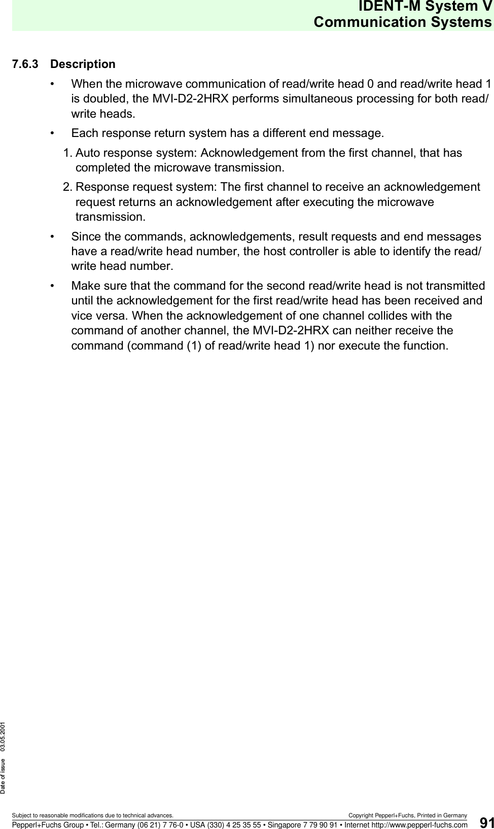
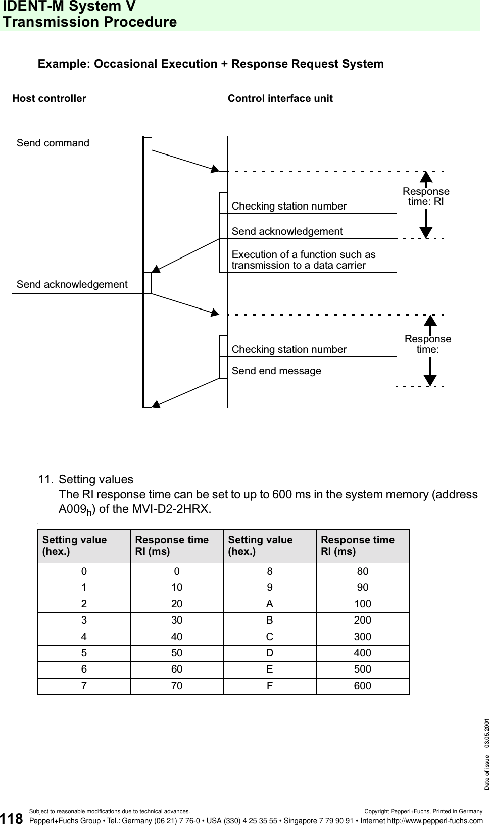
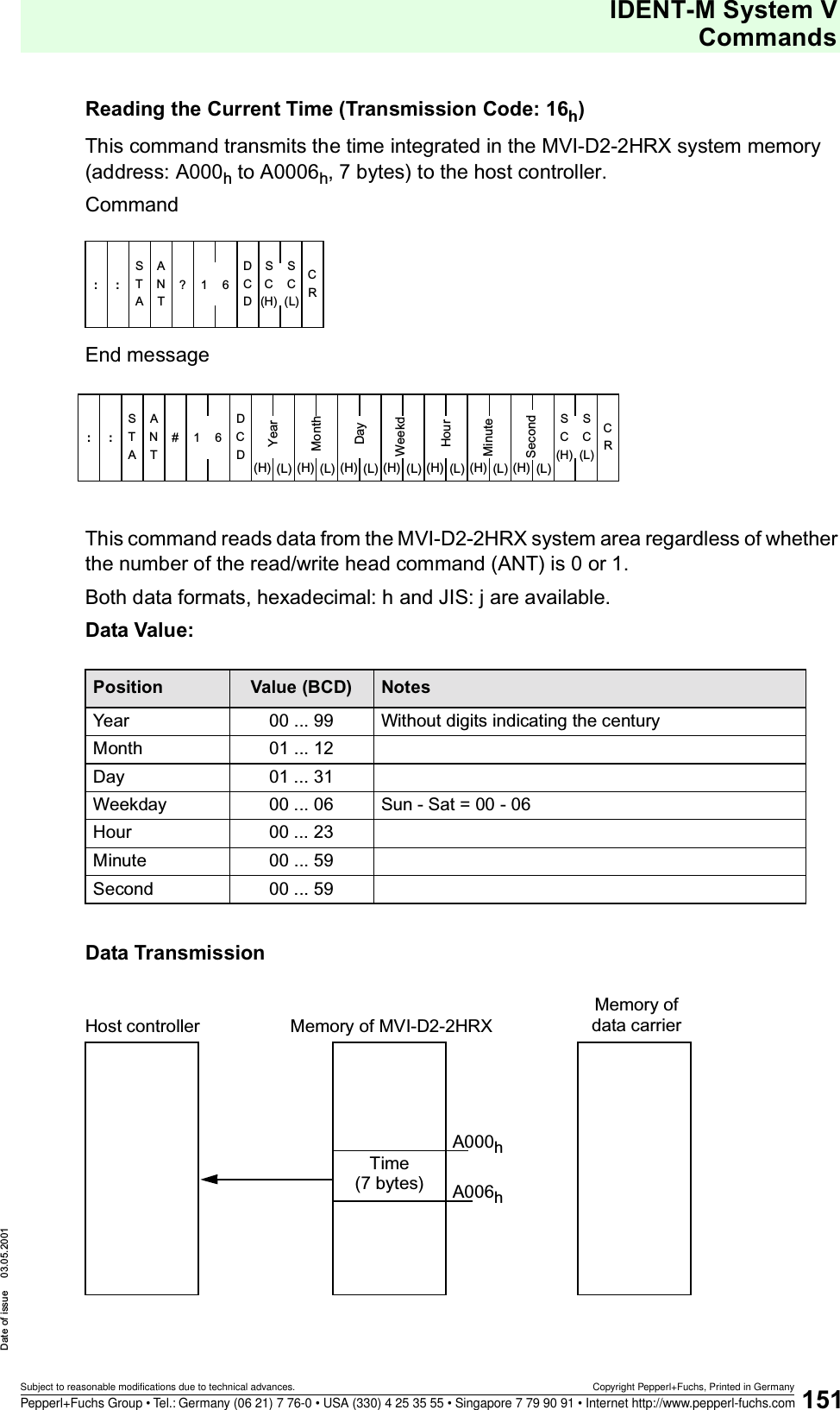
![IDENT-M System V Transmission ProcedureDate of issue 03.05.2001116Subject to reasonable modifications due to technical advances. Copyright Pepperl+Fuchs, Printed in GermanyPepperl+Fuchs Group • Tel.: Germany (06 21) 7 76-0 • USA (330) 4 25 35 55 • Singapore 7 79 90 91 • Internet http://www.pepperl-fuchs.com8. Communication startup systemThe communication startup system is determined by the contents of the MVI-D2-2HRX memory address A008h.In order to change the communication startup system, the content of the storage cell A008h should be overwritten and then the supply voltage of the control interface unit has to be switched OFF and then ON again.9. Response time (RI)This function is used when the MVI-D2-2HRX returns another message immediately after instruction execution, while the host controller is still processing previous data. 10. Contents (between host controller and each MVI-D2-2HRX) [In the case of the auto response systems]This function is available, in order to insert a time interval in between the command and the “sending of acknowledgement”.Protocol data 10032ExecutioncontentsCommand 9D6F 1Attribute 9D70 1ID code 9D71 4Start address 9D75 2Number of bytes 9D77 2Target area start address 9D79 2No data carrier error 9D7B 7Asynchronous error 9D7C 1Time-out error during the last reception of data 9D7D 1Byte counter error 9D7E 1Check sum error 9D7F 1Grammatical error 9D80 1Reserved area 9D81 1Area name of memory Address Setting contents Initial valueCommunication startup systemA008h00h= Occasionalexecution system00h (Occasional execution system)01h= Command stay system02h= Command register system03h= Read/write head scan systemItem Number of bytes Detailed item (contents) Start address hex. hNumber of bytes](https://usermanual.wiki/Pepperl-Fuchs/MVI.Manual/User-Guide-227994-Page-118.png)
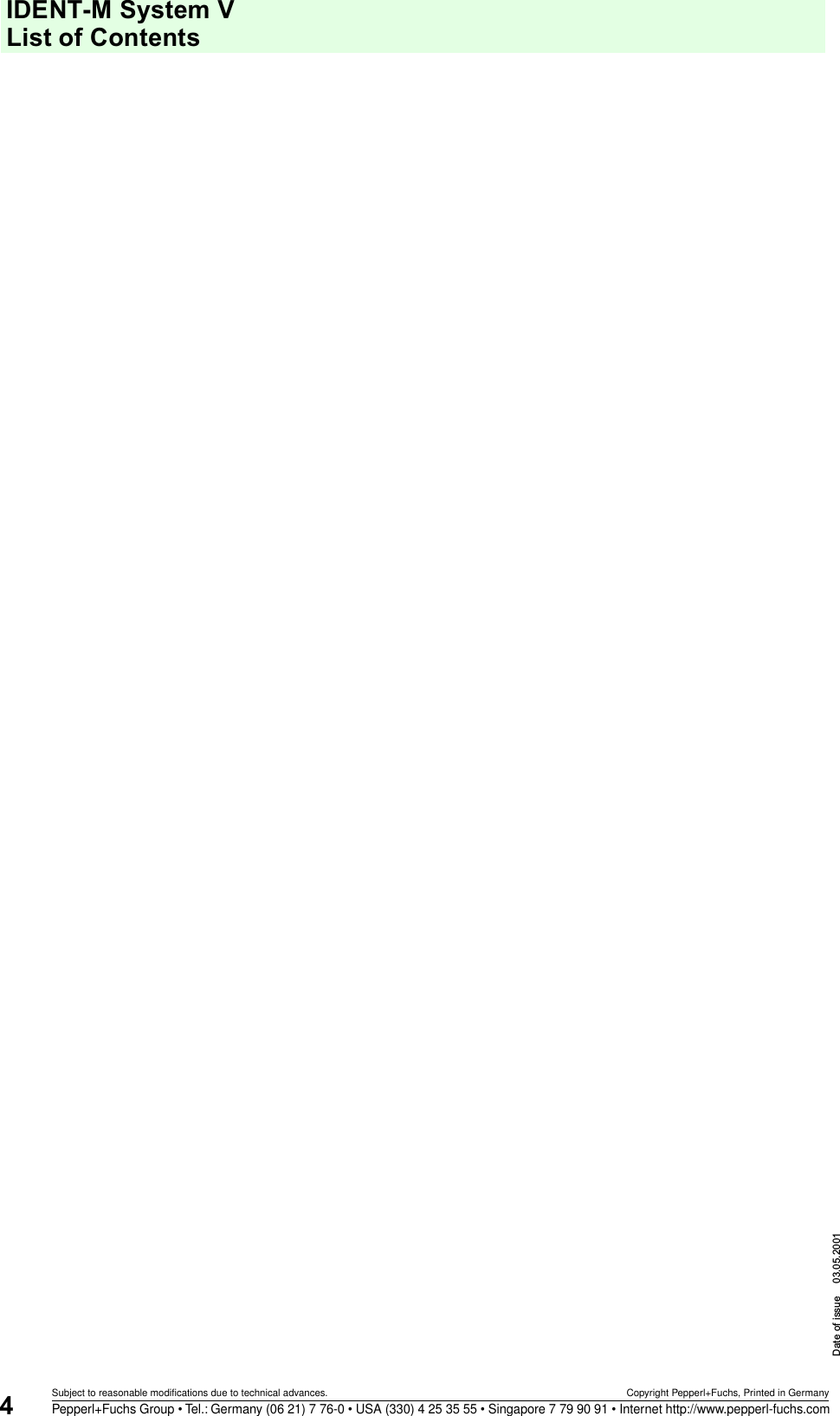
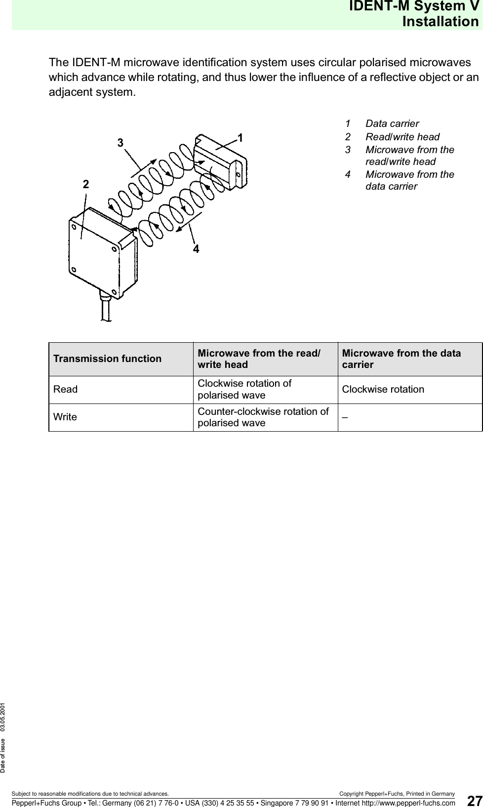
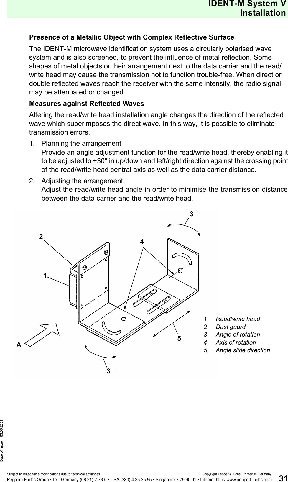
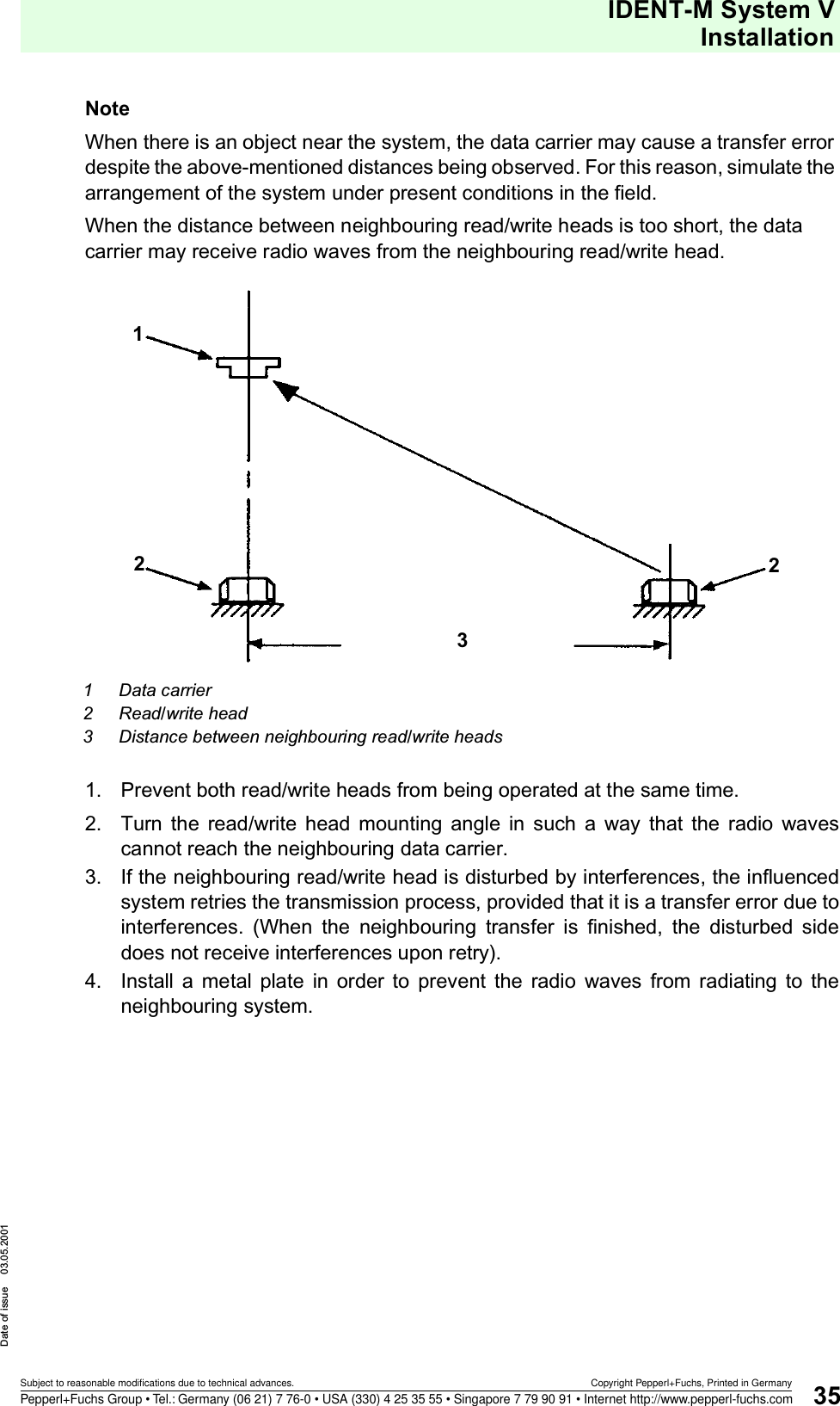
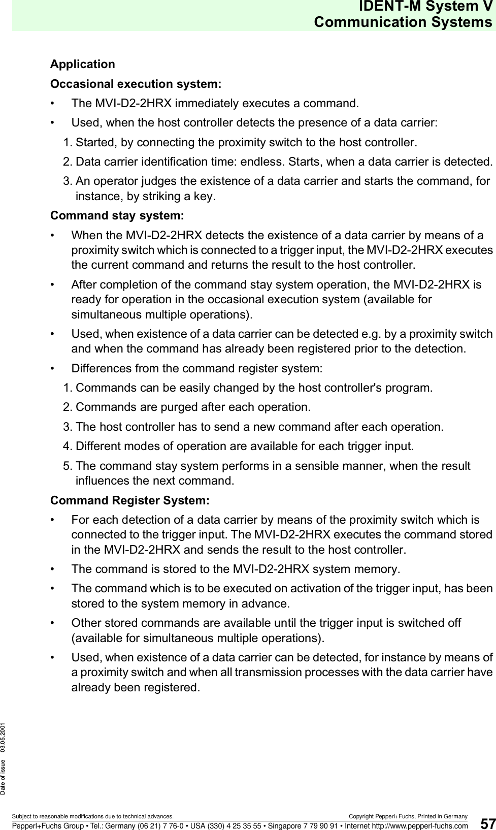
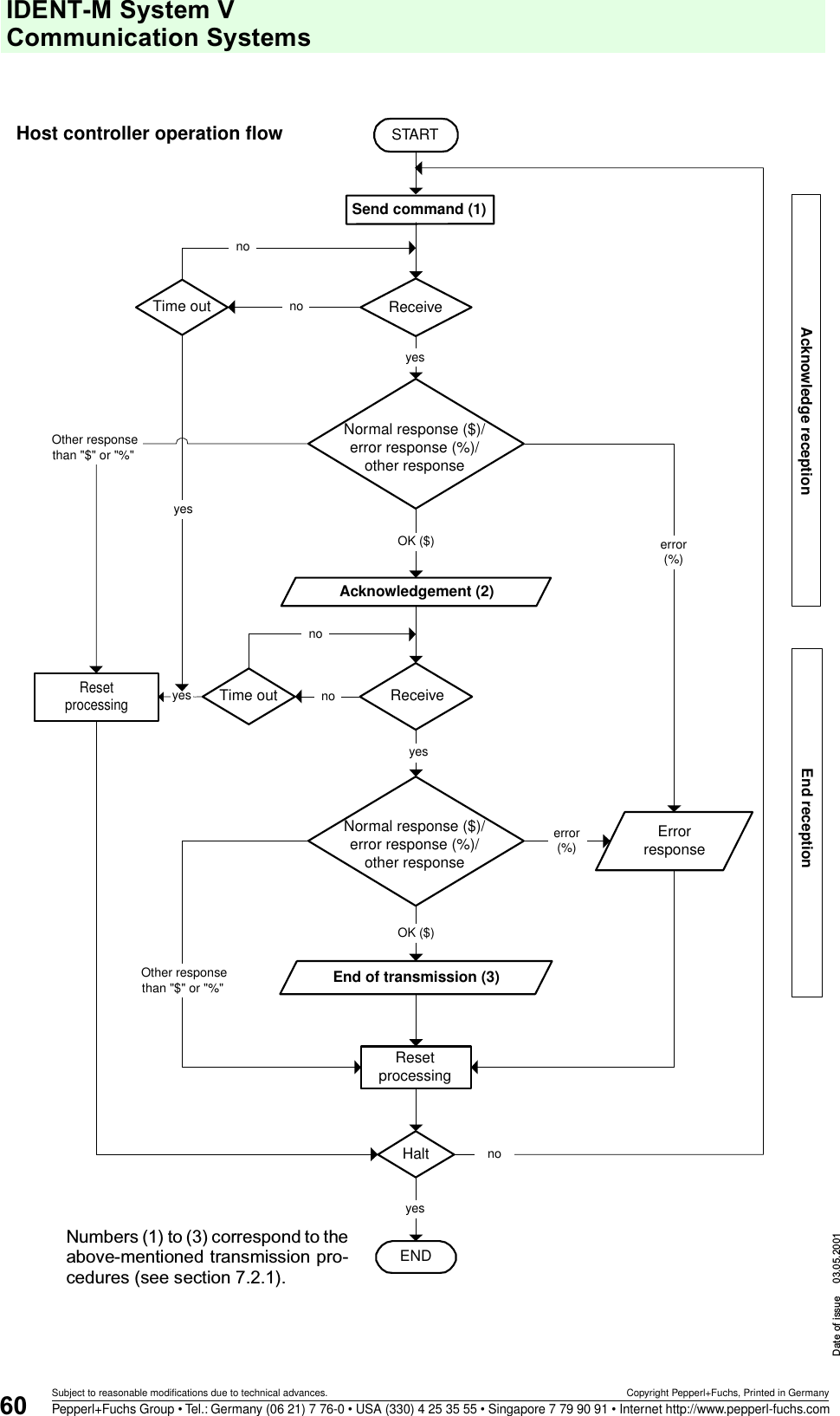
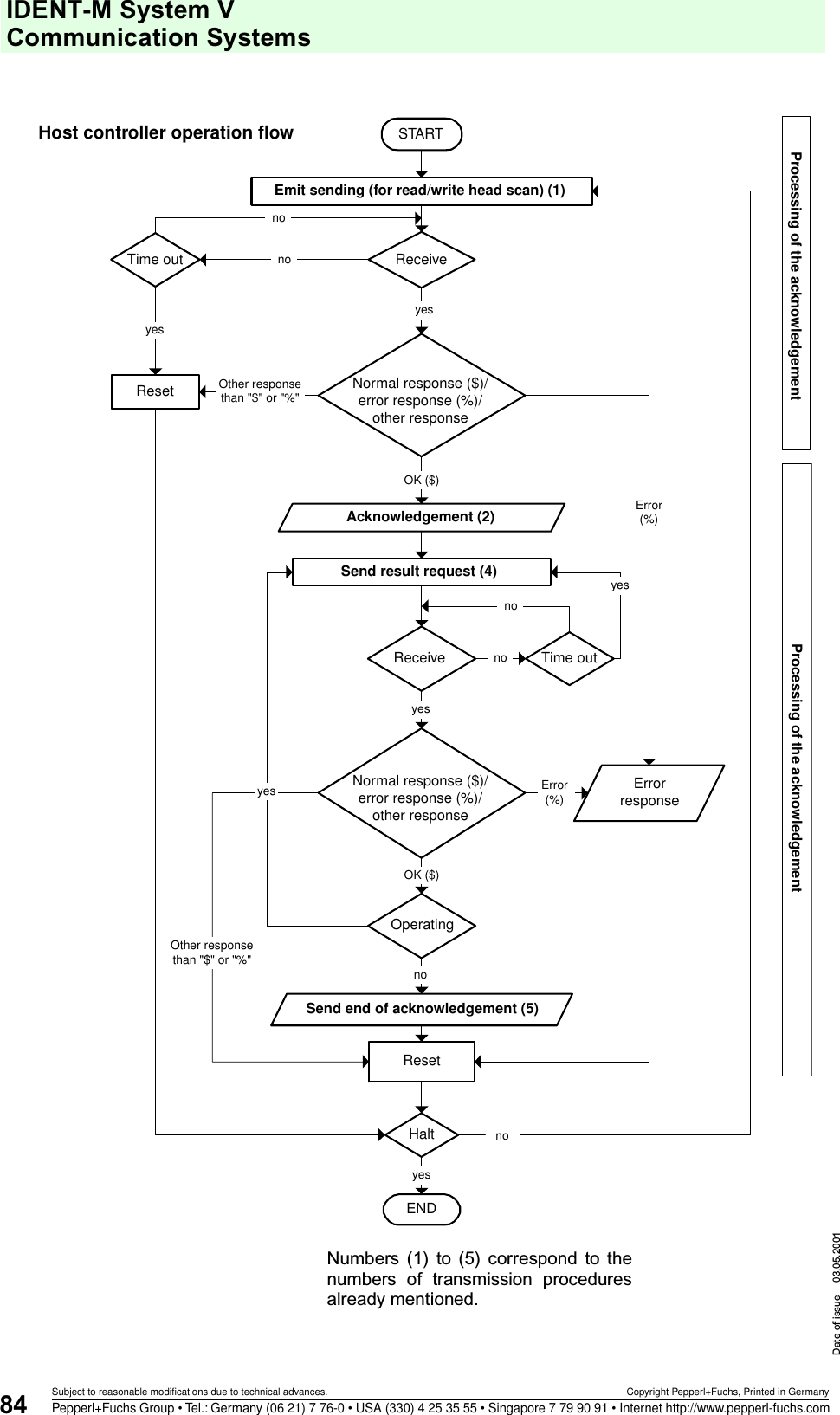
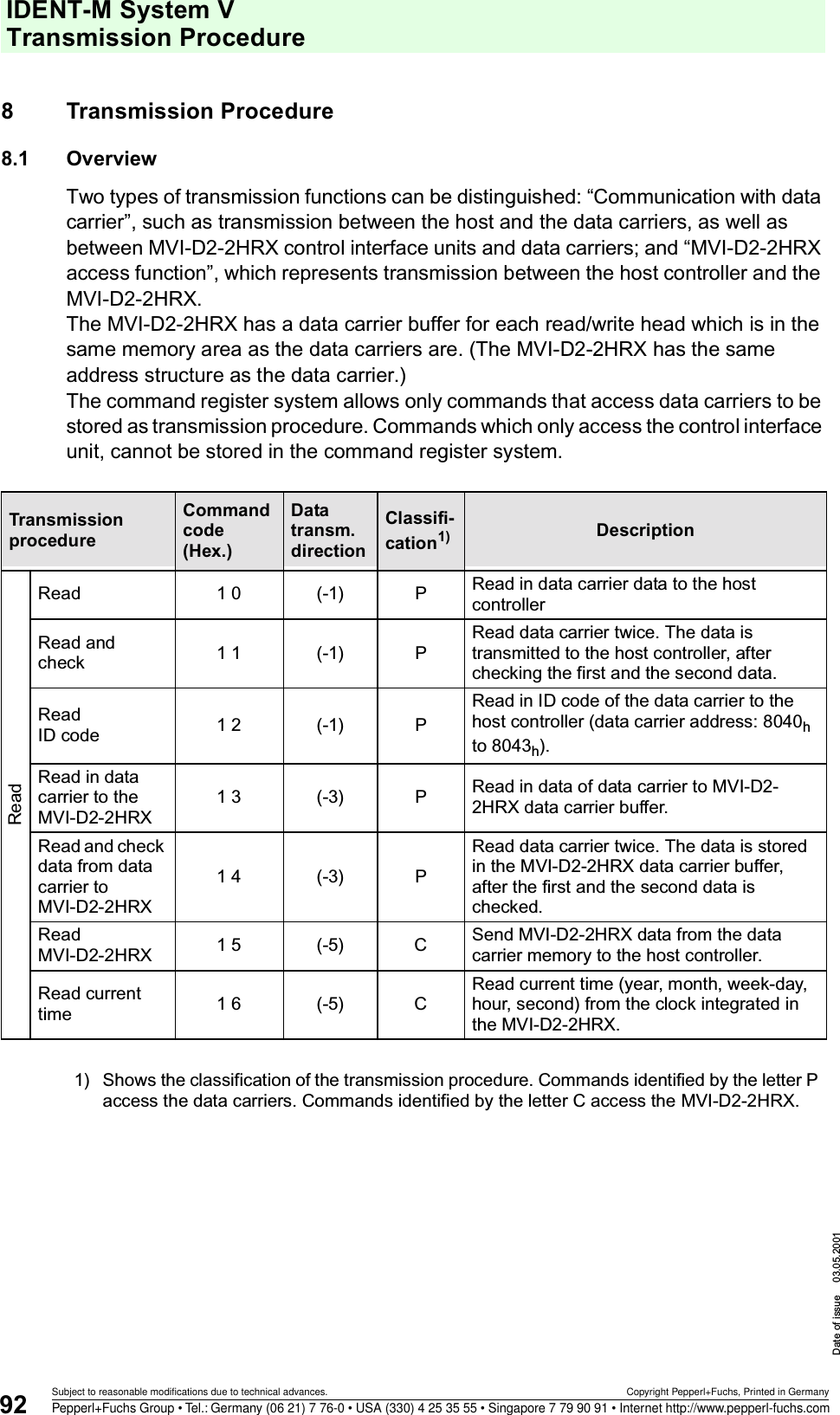
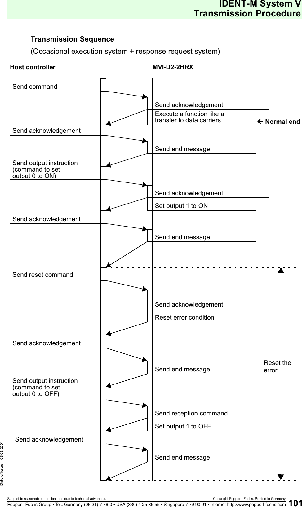
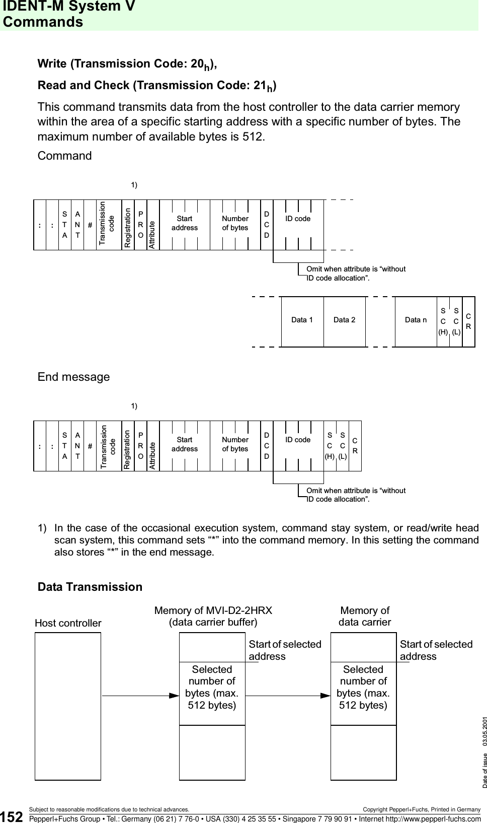
![IDENT-M System VTransmission ProcedureDate of issue 03.05.2001117Subject to reasonable modifications due to technical advances. Copyright Pepperl+Fuchs, Printed in GermanyPepperl+Fuchs Group • Tel.: Germany (06 21) 7 76-0 • USA (330) 4 25 35 55 • Singapore 7 79 90 91 • Internet http://www.pepperl-fuchs.comExample: Occasional Execution + Auto Response System• When the processing time between the read/write head and the data carrier is longer than the RI setting value, an end message is sent at the end of the processing between the read/write head and the data carrier.• When the processing time between the read/write head and the data carrier is shorter than the RI setting value after sending the acknowledgement, the MVI-D2-2HRX delays transmission of the end message with the RI setting value. [In the case of the response request systems]This function is available, in order to insert an interval between receiving the command and sending the acknowledgement as well as between receiving the acknowledgement request and sending the end message.Execution of a function such as transmission to a data carrierSend commandSend end messageControl interface unitHost controllerResponse time: RISend acknowledgement*Period of time until end message is sent*](https://usermanual.wiki/Pepperl-Fuchs/MVI.Manual/User-Guide-227994-Page-119.png)
![IDENT-M System V CommandsDate of issue 03.05.2001128Subject to reasonable modifications due to technical advances. Copyright Pepperl+Fuchs, Printed in GermanyPepperl+Fuchs Group • Tel.: Germany (06 21) 7 76-0 • USA (330) 4 25 35 55 • Singapore 7 79 90 91 • Internet http://www.pepperl-fuchs.com9.3.3 Command Stay System + Auto Response SystemSATATN?::S(H)CS(L)CRCSATATN::S(H)CS(L)CRC$Error messageExecute command (e.g. communication with a data carrier)SATATN::S(H)CS(L)CRC#SATATN::S(H)CS(L)CRC%E(H)KE(L)KE(L)CE(H)COKOKNGNGEnd messageAcknowledgementCom-mand contentsResultError informa-tionSATATN?::S(H)CS(L)CRCSATATN::S(H)CS(L)CRC$Execute command (e.g. communication with a data carrier)SATATN::S(H)CS(L)CRC#OKOKNGNGEnd responseAcknowledgementCom-mand contentsResult71S(H)CS(L)CRCSATATN?::CommandError messages are indicated when errors occur during the acknowl-edgement or the end message.[Trigger input ON]CommandSwitches on the occasional execution system while the trigger input is ON.Host MVI-D2-2HRX71S(H)CS(L)CRCSATATN?::Acknowledgement requestAcknowledgement request](https://usermanual.wiki/Pepperl-Fuchs/MVI.Manual/User-Guide-227994-Page-130.png)
![IDENT-M System VCommandsDate of issue 03.05.2001129Subject to reasonable modifications due to technical advances. Copyright Pepperl+Fuchs, Printed in GermanyPepperl+Fuchs Group • Tel.: Germany (06 21) 7 76-0 • USA (330) 4 25 35 55 • Singapore 7 79 90 91 • Internet http://www.pepperl-fuchs.com9.3.4 Command Stay System + Response Request SystemSATATN?::S(H)CS(L)CRCSATATN::S(H)CS(L)CRC$Error messageExecute command (e.g. communication with a data carrier)SATATN::S(H)CS(L)CRC#SATATN::S(H)CS(L)CRC%E(H)KE(L)KE(L)CE(H)COKOKNGNGEnd messageAcknowledgementCom-mand contentsResultError informa-tion71S(H)CS(L)CRCSATATN?::SATATN?::S(H)CS(L)CRCSATATN::S(H)CS(L)CRC$Execute command (e.g. communication with a data carrier)SATATN::S(H)CS(L)CRC#OKOKNGNGAcknowledgement requestAcknowledgementCom-mand contentsResult71S(H)CS(L)CRCSATATN?::CommandError messages are indicated when errors occur during the acknowl-edgement or the end message.Acknowledgement requestCommandAcknowledgement requestSwitches on the occasional execution system while the trigger input is ON.[Trigger input ON]Host MVI-D2-2HRX](https://usermanual.wiki/Pepperl-Fuchs/MVI.Manual/User-Guide-227994-Page-131.png)
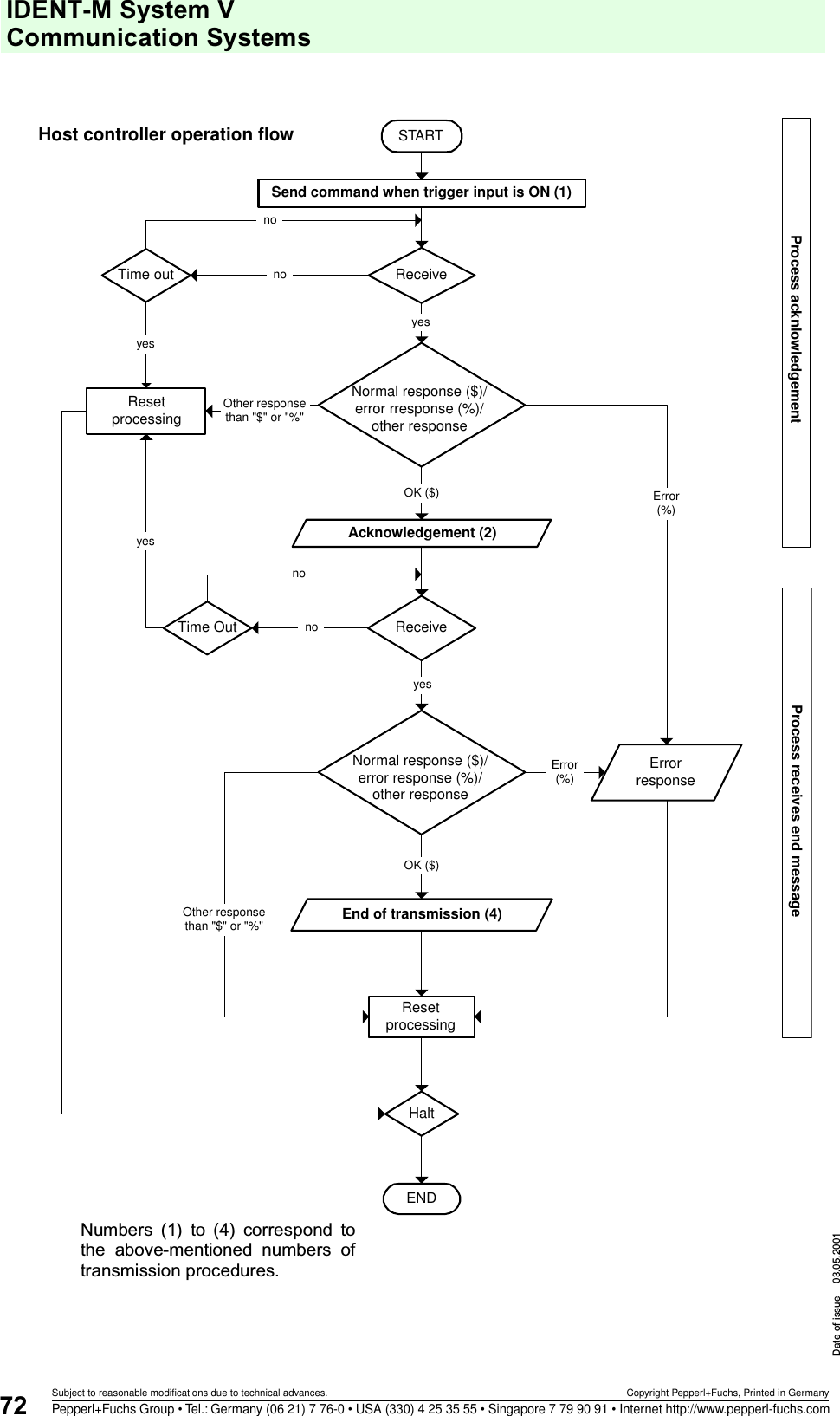
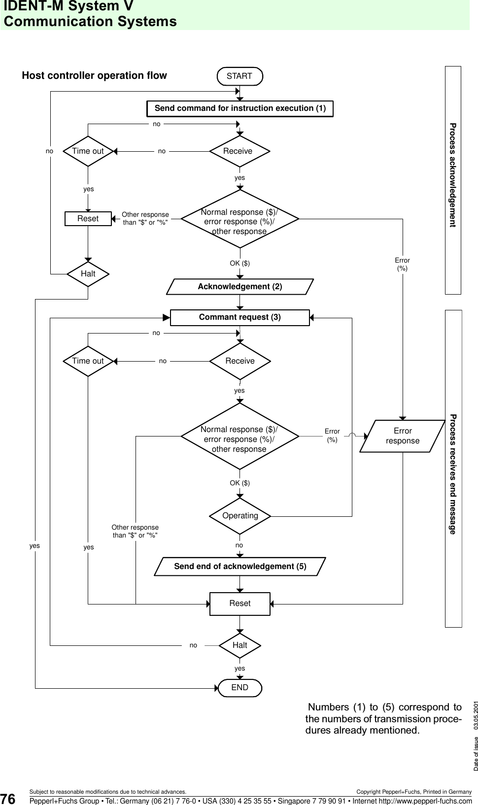
![IDENT-M System V CommandsDate of issue 03.05.2001130Subject to reasonable modifications due to technical advances. Copyright Pepperl+Fuchs, Printed in GermanyPepperl+Fuchs Group • Tel.: Germany (06 21) 7 76-0 • USA (330) 4 25 35 55 • Singapore 7 79 90 91 • Internet http://www.pepperl-fuchs.com9.3.5 Command Register System + Auto Response SystemSATATN?::S(H)CS(L)CRCSATATN::S(H)CS(L)CRC$Error messageExecute command (e.g. communication with a data carrier)SATATN::S(H)CS(L)CRC#SATATN::S(H)CS(L)CRC%E(H)KE(L)KE(L)CE(H)COKOKNGNGEnd message (for a stored command) AcknowledgementResultError informa-tionSATATN?::S(H)CS(L)CRCSATATN::S(H)CS(L)CRC$Execute command (e.g. communication with a data carrier)SATATN::S(H)CS(L)CRC#OKOKNGNGEnd message (for a stored command)AcknowledgementResultS(H)CS(L)CRCCommand (when trigger input is ON)Error messages are indicated when errors occur during the acknowl-edgement or the end message.Start next command75[Trigger input ON]Repeat at each turn ON of the trigger inputEnables commands as long as the trigger input is ON.67Host MVI-D2-2HRX](https://usermanual.wiki/Pepperl-Fuchs/MVI.Manual/User-Guide-227994-Page-132.png)
![IDENT-M System VCommandsDate of issue 03.05.2001131Subject to reasonable modifications due to technical advances. Copyright Pepperl+Fuchs, Printed in GermanyPepperl+Fuchs Group • Tel.: Germany (06 21) 7 76-0 • USA (330) 4 25 35 55 • Singapore 7 79 90 91 • Internet http://www.pepperl-fuchs.com9.3.6 Command Register System + Response Request SystemSATATN?::S(H)CS(L)CRCSATATN::S(H)CS(L)CRC$Error messageExecute command (e.g. communication with a data carrier)SATATN::S(H)CS(L)CRC#SATATN::S(H)CS(L)CRC%E(H)KE(L)KE(L)CE(H)COKOKNGNGEnd message (for a stored command) AcknowledgementResultError informa-tionSATATN?::S(H)CS(L)CRCSATATN::S(H)CS(L)CRC$Execute command (e.g. communication with a data carrier)SATATN::S(H)CS(L)CRC#OKOKNGNGEnd message (for a stored command)AcknowledgementResultS(H)CS(L)CRCCommand (when trigger input is ON)Error messages are indicated when errors occur during the acknowl-edgement or the end message.Start next command75[Trigger input ON]Repeat at each turn ON of the trigger inputEnables commands as long as the trigger input is ON.6771S(H)CS(L)CRCSATATN?::Acknowledgement requestHost MVI-D2-2HRX71S(H)CS(L)CRCSATATN?::Acknowledgement request](https://usermanual.wiki/Pepperl-Fuchs/MVI.Manual/User-Guide-227994-Page-133.png)

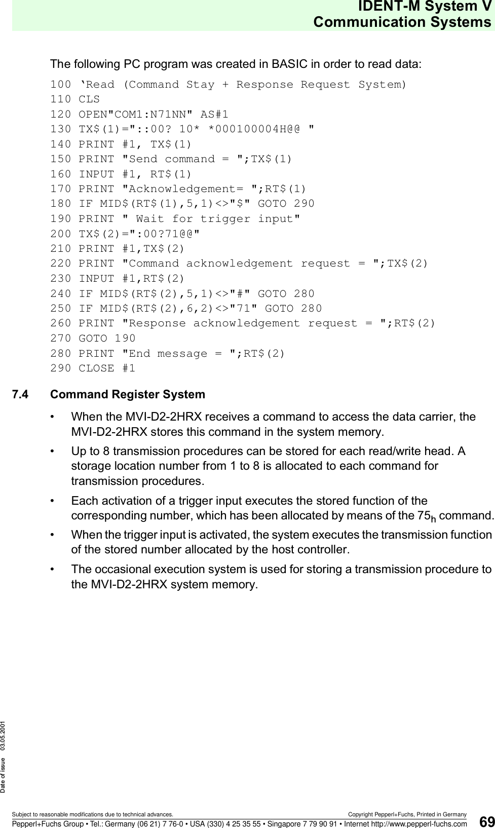
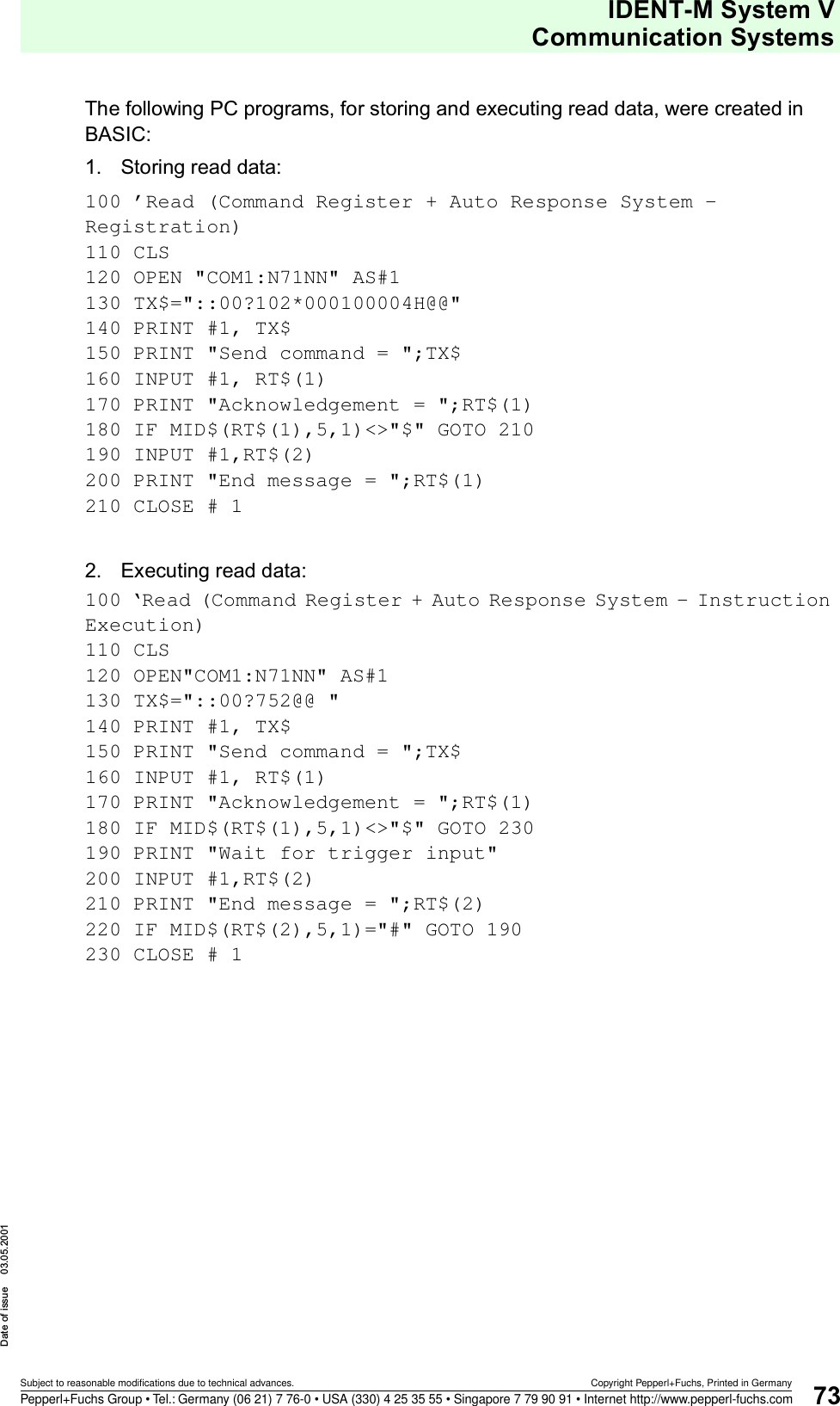
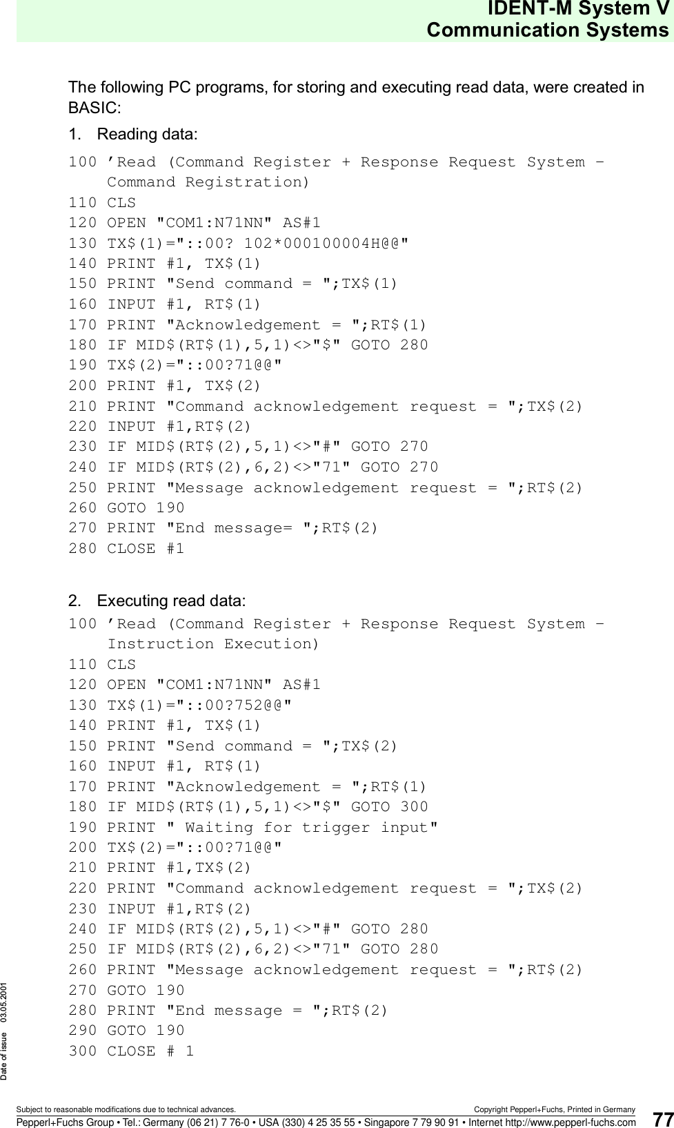
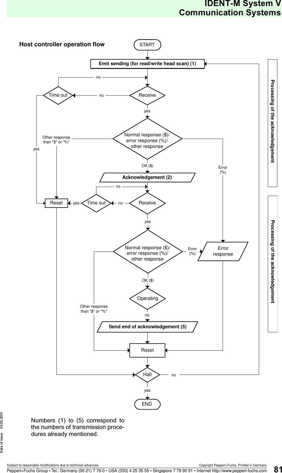
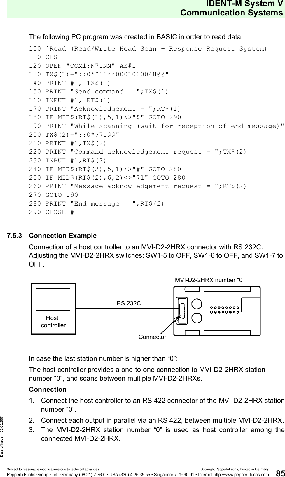
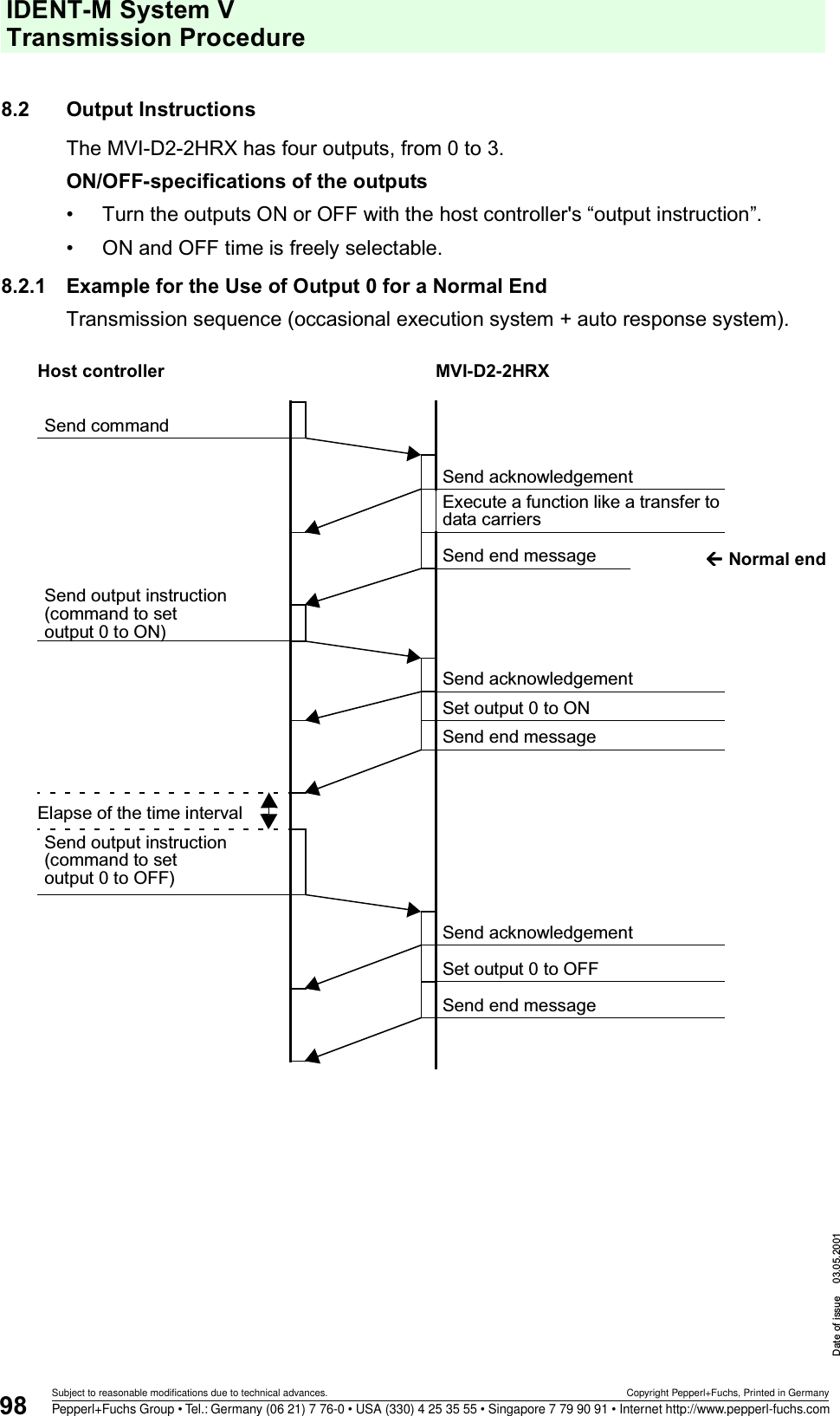
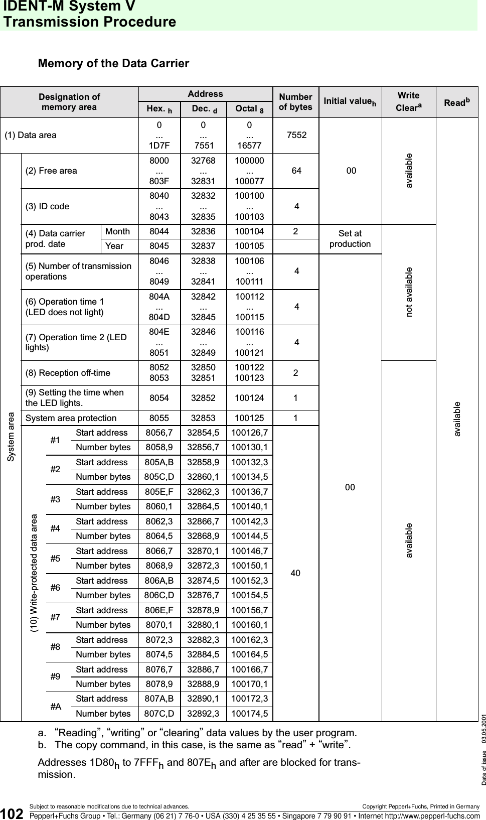
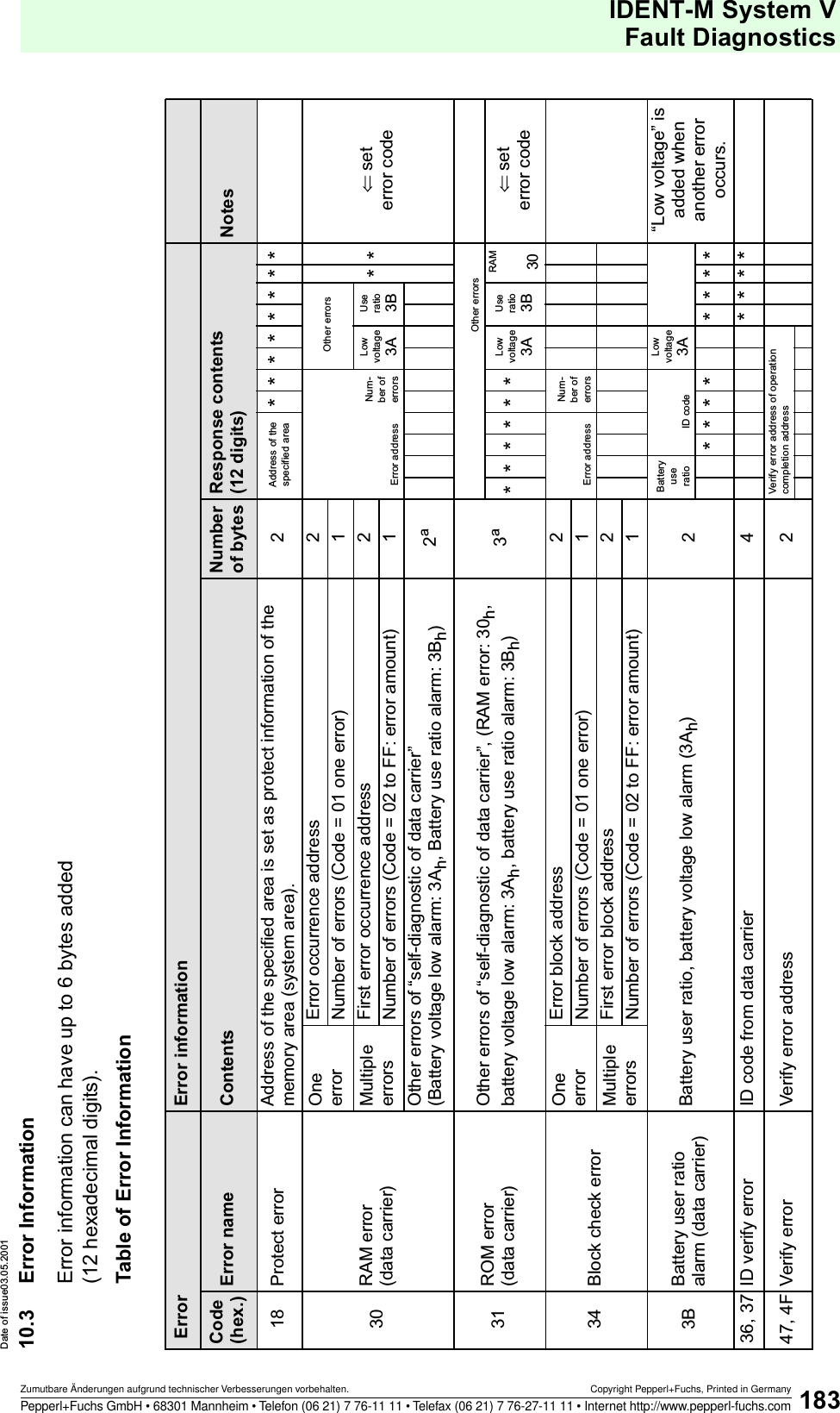
![IDENT-M System V Fault DiagnosticsDate of issue 03.05.2001182Subject to reasonable modifications due to technical advances. Copyright Pepperl+Fuchs, Printed in GermanyPepperl+Fuchs Group • Tel.: Germany (06 21) 7 76-0 • USA (330) 4 25 35 55 • Singapore 7 79 90 91 • Internet http://www.pepperl-fuchs.comProgram operation error62Blocking due to error at command executionReceiving another command than the reset command after an error between read/write head an the data carrier (error releasable only by the reset command).End1*63Blocking the command execution at trigger input OFFReceiving “next operation start command” or “re-execution command” when trigger input is OFF.64No command register error[Command register system]Not registered operation in the specific area even if receiving “operation instruction command when trigger input is ON”.65No startup command errorReceiving “re-execution command” or “next operation start command” without previous receiving of “operation instruction command” when trigger input is ON [Command register system].0066Communication startup system setting errorSend “operation instruction command when trigger input is ON”, “next operation start command” or “re-execution command” in another than the command register system.Receiving a read/write head scan command without adjusted read/write head scan system.67Register not available Read/write head of the specific area is on the copy source side of the copying operation at “operation instruction command when trigger input is ON”.Program operation error68Halt command receive errorReceived “halt command” at the following conditions:· Occasional execution system· Command stay system· No received “operation instruction command when trigger input is ON” in the command register system. (address 9010h Do not scan in the read/write head scan system.)End 0069Error at receiving the result requestReceiving another command than “result request” while waiting for result request in the response request system.· Receiving the result request although not expected.70 Time out between two codesTime out error at transfer of two codes between host controller and MVI-D2-2HRX.72Time out between station number “0” and station number “N” Time out error between “0” and station number “N” in the read/write head scan system.73Checksum error between station number “0” and station “N”Checksum error between station number “0” and station number “N” in the read/write head scan system.74CR error between station number “0” and station number “N”Incorrect “CR” between station number “0” and station number “N” in the read/write head scan system.Error classi-ficationError code (EC)Error name ContentsHost controller response aError position (EK) b](https://usermanual.wiki/Pepperl-Fuchs/MVI.Manual/User-Guide-227994-Page-184.png)
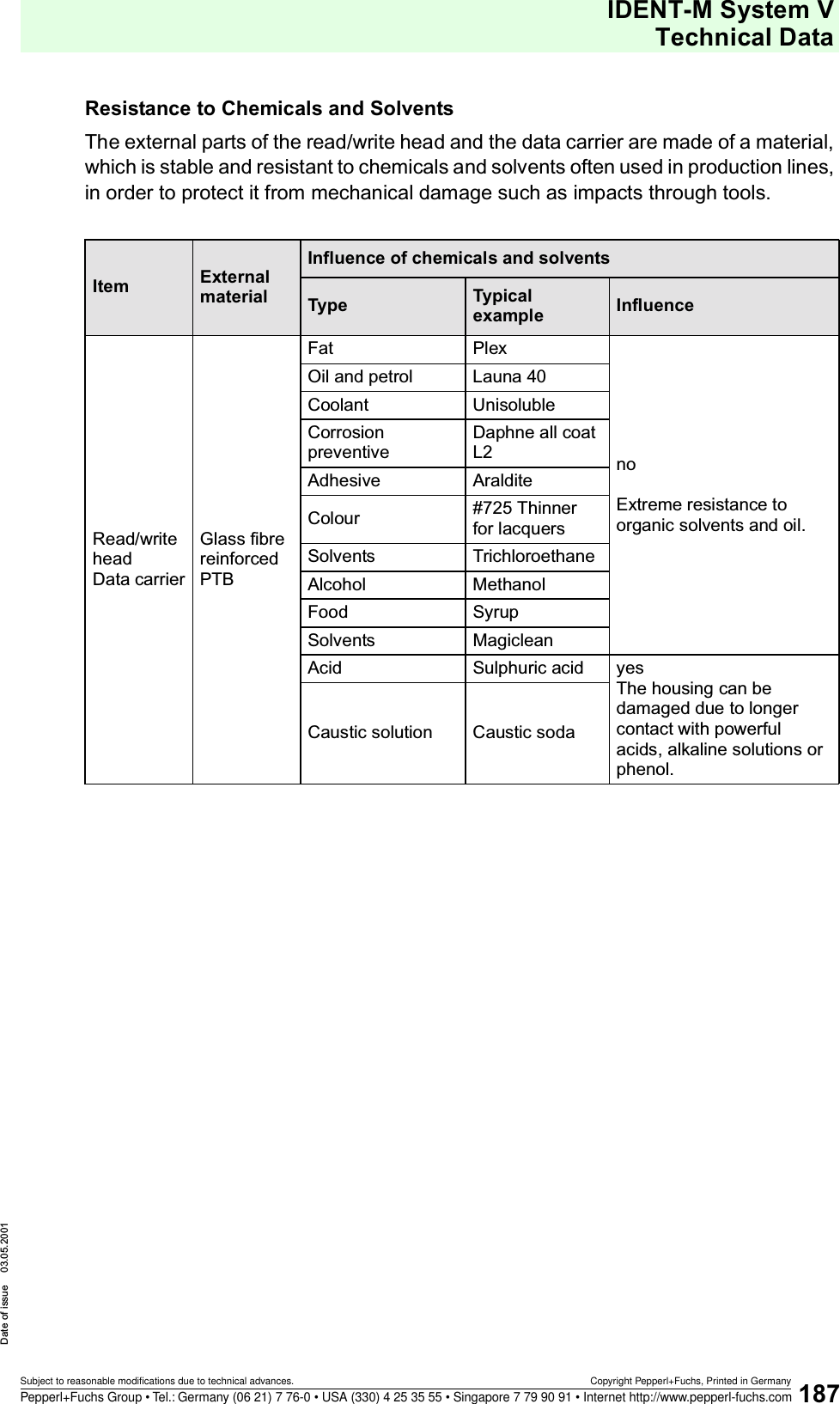
![IDENT-M System VTechnical DataDate of issue 03.05.2001191Subject to reasonable modifications due to technical advances. Copyright Pepperl+Fuchs, Printed in GermanyPepperl+Fuchs Group • Tel.: Germany (06 21) 7 76-0 • USA (330) 4 25 35 55 • Singapore 7 79 90 91 • Internet http://www.pepperl-fuchs.comExampleWith an average number of 32 bytes per transmission during the reading process (transmission code: 0208), with the data carrier (MVC-60-64K) and the conditions mentioned below, the average lifetime L will be approx. 8.27 years.Battery life L (year) A = 1,600 * 0.9 365 * 24 [A * active current + (1 - A) * standby current]1,900 Battery capacity (mAh)0.9 Safety deduction (taking into account the data carrier's production and delivery time)365 365 days/year 24 24 h/day A Activation periodActive current : approx. 12 mA or less (when the LED is not illuminated) Standby current: approx. 20 µA or less15.9 * 2000 300Tc = 11.3 + 0.143 * 32 + M1( ) * 0.5 + M2 ( ) * 5.59 = 15.9 (ms)128Battery life L (year) A = = 8.27 1900 * 0.9 365 * 24 [0.0003 * 12 + (1 - 0.0003) * 0.02]Activation rate A = * = 0.000324*3600*1000 36532 32256N 2000 number/day D 300 days/yearActive current 12 mA Standby current 20 µA = 0.020 mA](https://usermanual.wiki/Pepperl-Fuchs/MVI.Manual/User-Guide-227994-Page-193.png)
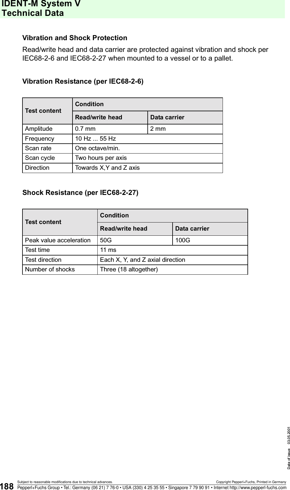
![IDENT-M System V Technical DataDate of issue 03.05.2001192Subject to reasonable modifications due to technical advances. Copyright Pepperl+Fuchs, Printed in GermanyPepperl+Fuchs Group • Tel.: Germany (06 21) 7 76-0 • USA (330) 4 25 35 55 • Singapore 7 79 90 91 • Internet http://www.pepperl-fuchs.comChecking the Battery LifeCheck the service life and the battery voltage of the battery integrated in the data carrier by means of the transmission function between the host controller and the data carrier (checking the battery life of the data carrier and self-diagnosis of the data carrier).• If an error is found during the test, the data carrier sends an error message to the host controller (service life alarm or low battery voltage alarm, see page 185).In case the battery functions properly, the data carrier sends an acknowledgement containing the battery utilisation rate. In case the battery voltage is too low, the corresponding error message is added to the acknowledgement. This is also done, in case other communication operations are conducted at the same time (see page 185).Be sure to substitute the data carrier immediately, in case one of these errors occurs.• Battery utilisation rate (%)Error code Error designation Explanation3A Low battery voltage alarm Voltage level of battery is too low3B Battery service life alarm Battery service life exceeds 100 %Standby time Current year and month - production year and month - active operation time 1 -0.02 Standby current (20 mA = 0.020 mA)Active operation time1While the data carrier communicates with the read/write head, the LED on the data carrier does not light. (Stores data in the memory addresses 804A to 804Dh of the data carrier).12 Current = 12 mA Active operation time2While the data carrier communicates with the read/write head, the LED on the data carrier lights. (Stores data in the memory addresses 804A to 8051Dh of the data carrier).15 Current = 15 mA (during communication with the read/write head and illuminated LED on the data carrier).1,900 Battery capacity (1,900 mA • h)0.9 Safety deduction (In order to take into account the time interval between production and sale of the data carrier).Battery utilisation rate =Standby time * 0.02 + active operation time1 + 12 + active operation time2 * 151900 * 0.9 * 100 [%]](https://usermanual.wiki/Pepperl-Fuchs/MVI.Manual/User-Guide-227994-Page-194.png)
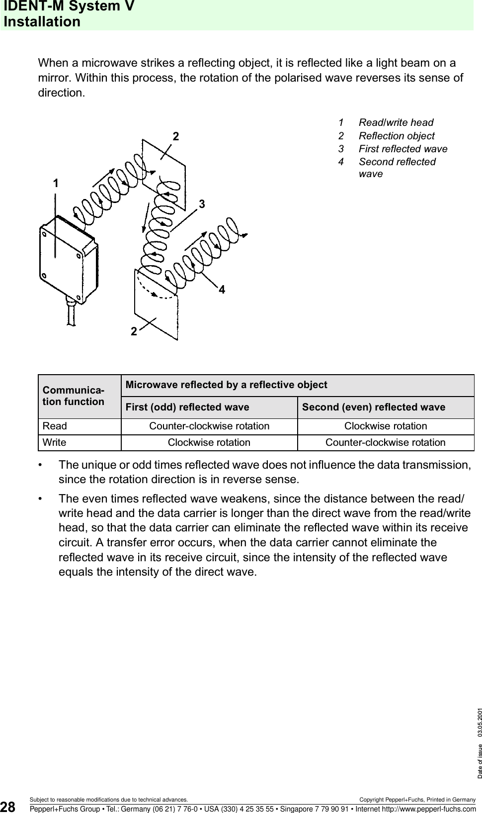
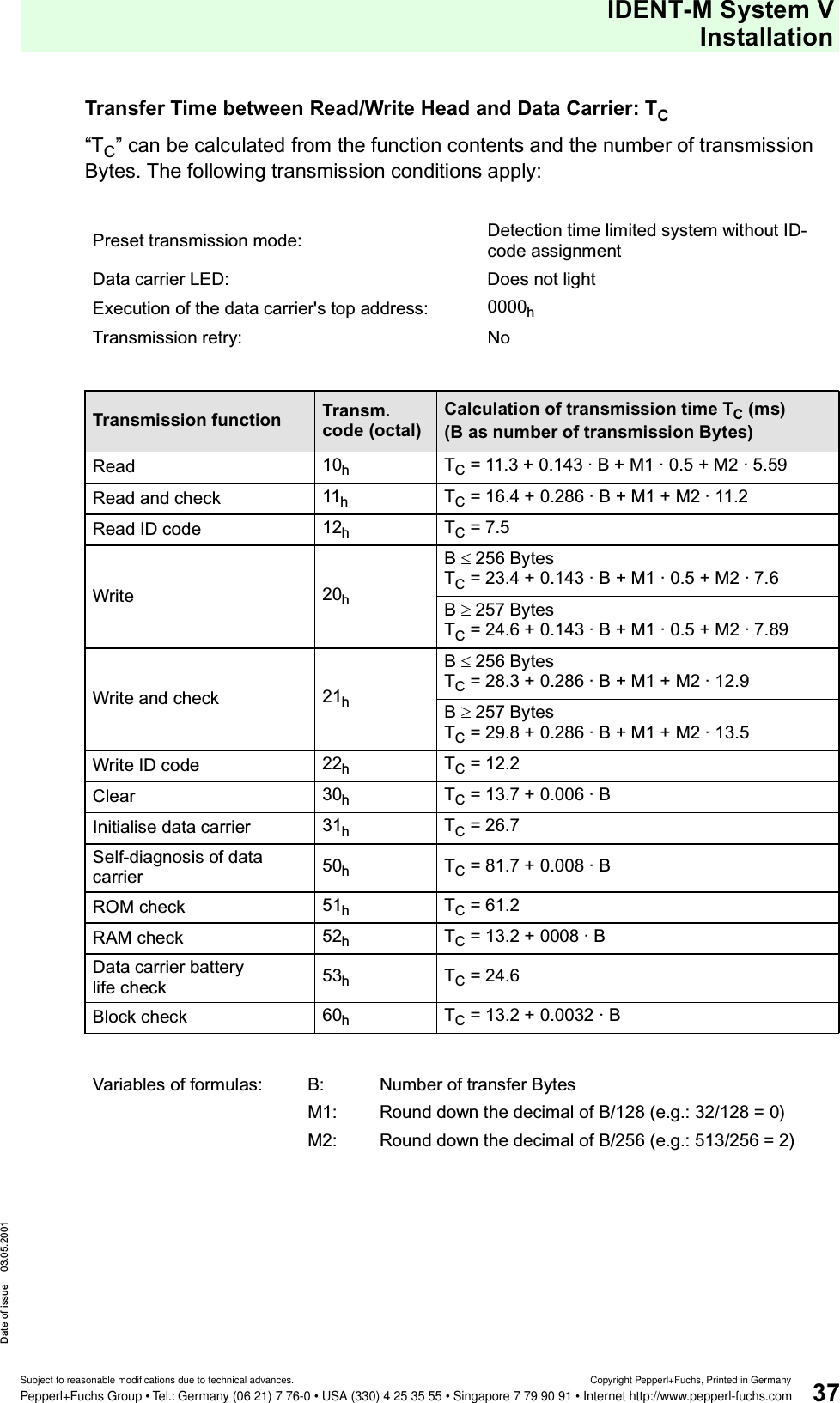
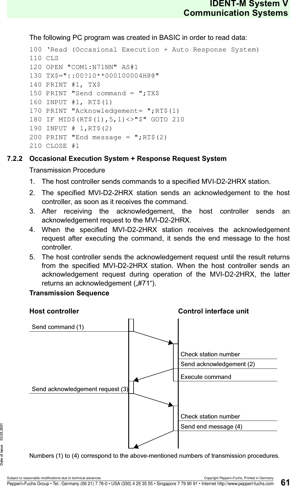
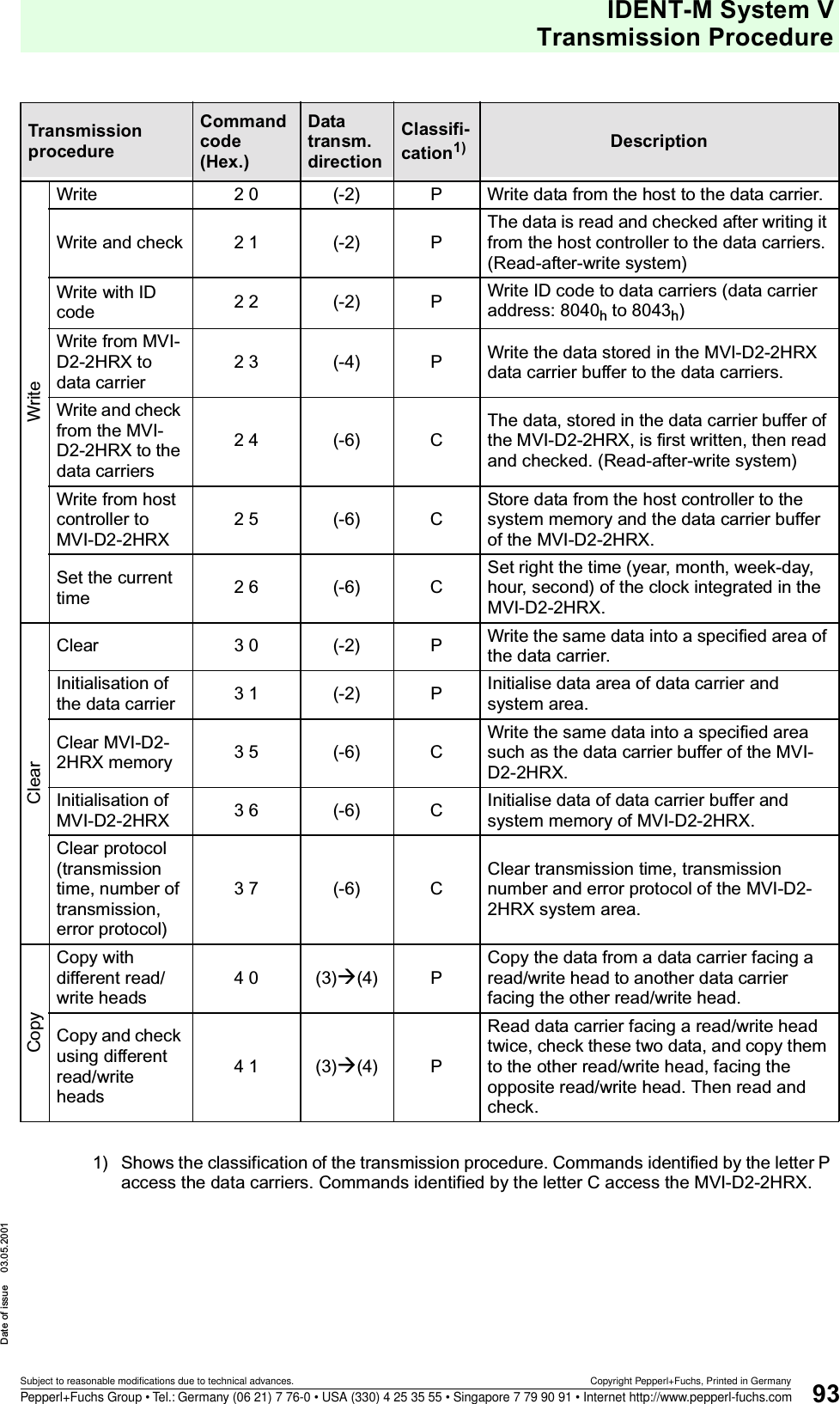
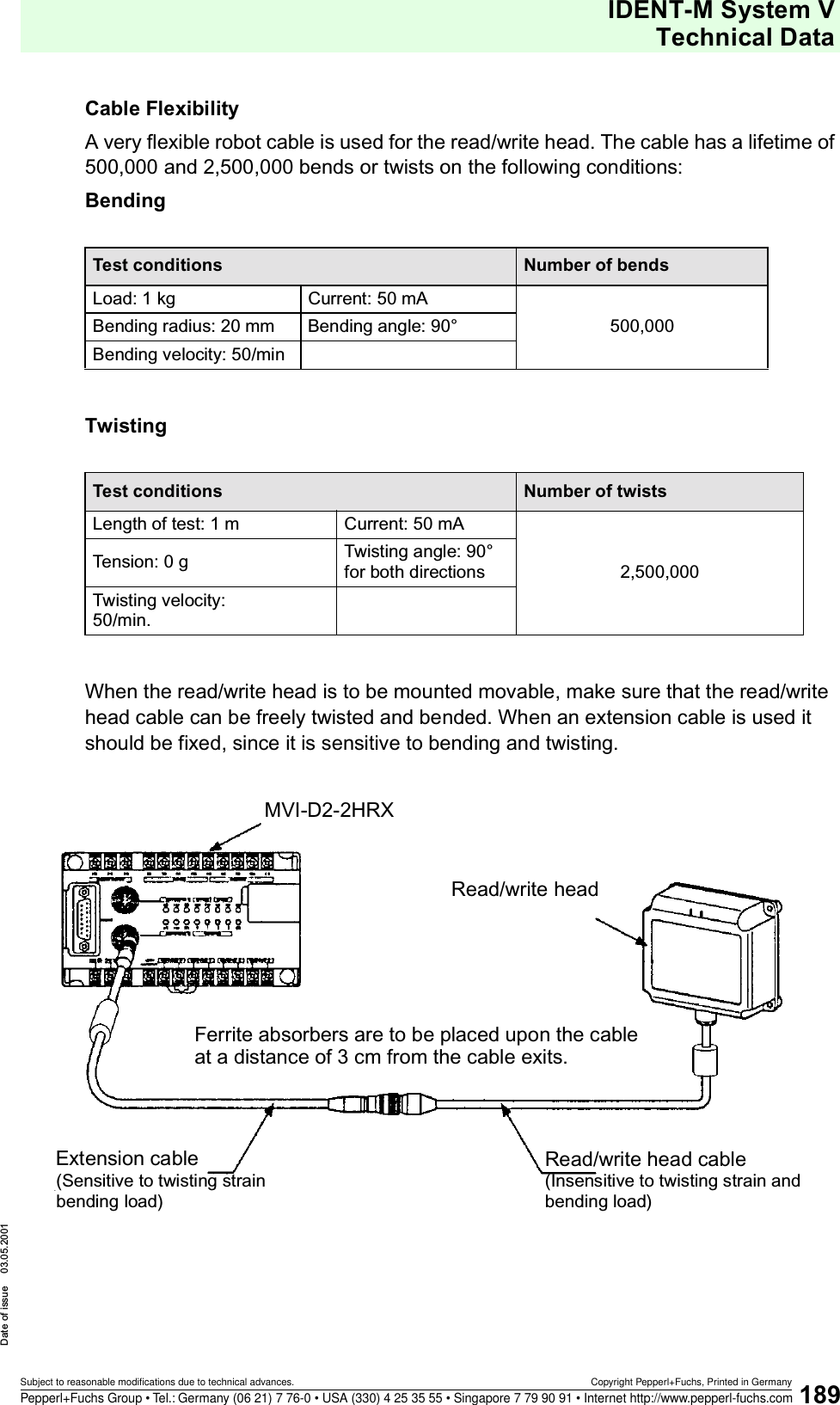
![IDENT-M System VAppendixDate of issue 03.05.2001193Subject to reasonable modifications due to technical advances. Copyright Pepperl+Fuchs, Printed in GermanyPepperl+Fuchs Group • Tel.: Germany (06 21) 7 76-0 • USA (330) 4 25 35 55 • Singapore 7 79 90 91 • Internet http://www.pepperl-fuchs.com12 Appendix12.1 ASCII (JIS) Code Table12.1.1 Binary/Hexadecimal Table• How to use an ASCII code tableCapital letter “A” is located on “4” of the higher-order bit and on “1” of the lower-order bit. Thus, the ASCII code of “A” is à “41h”.12.1.2 Octal TableHow to use an ASCII code tableCapital letter “A” is located on “10” of the upper two digits and on “1” of the lower digit. Thus, the ASCII code of “A” is à “1018”.Lower-order bitbin 0000 0001 0010 0011 0100 0101 0110 0111 1000 1001 1010 1011 1100 1101 1110 1111Higher-order bitbin hex 0 1 2 3 4 5 6 7 8 9 A B C D E F0000 0NUL SOH STX ETX EOT ENQ ACK BEL BS HT LF VT FF CR SO SI0001 1DLE DC1 DC2 DC3 DC4 NAK SYN ETB CAN EM SUB ESC FS GS RS US0010 2SP ! " # $ % & ' ( ) * + , - . /0011 30123456789 : ; <=>?0100 4@A B C D E F G H I J K L MN O0101 5PQRSTUVWXYZ[\]^_0110 6` abcde f gh i j k lmno0111 7pqrstuvwxyz{ | }~DELLower digitUpper two digitsoctal 0123456700 NUL SOH STX ETX EOT ENQ ACK BEL01 BS HT LF VT FF CR SO SI02 DLE DC1 DC2 DC3 DC4 NAK SYN ETB03 CAN EM SUB ESC FS GS RS US04 SP ! " # $ % & '05 ()*+,-./06 0123456707 89 : ; <=>?10 @A B C D E F G11 HIJKLMNO12 PQRSTUVW13 XYZ[\]^_14 `abcdefg15 hi jklmno16 pq r s t uvw17 xyz { | }~DEL](https://usermanual.wiki/Pepperl-Fuchs/MVI.Manual/User-Guide-227994-Page-195.png)
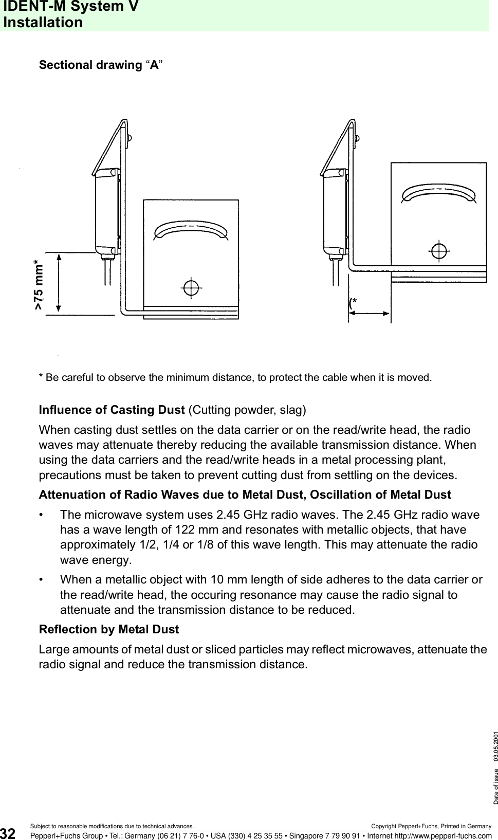
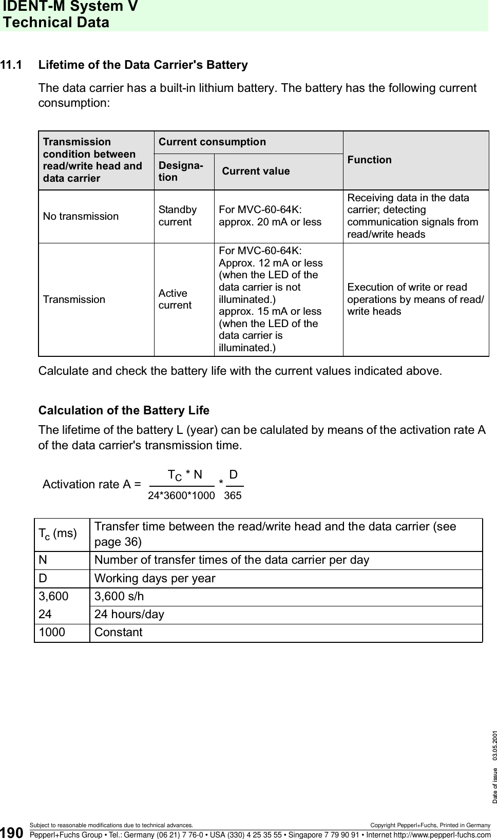
![IDENT-M System V AppendixDate of issue 03.05.2001196Subject to reasonable modifications due to technical advances. Copyright Pepperl+Fuchs, Printed in GermanyPepperl+Fuchs Group • Tel.: Germany (06 21) 7 76-0 • USA (330) 4 25 35 55 • Singapore 7 79 90 91 • Internet http://www.pepperl-fuchs.comCalculation ExamplesCalculation example for a maximum length of the extension cable (previous page). For a two wire cable, applying the following formula: RD = Rr *(Lm/1,000) * 2/2Maximum cable length Lm [m] = (RD ´ 1,000)/RrRD [9]: Permissible lead resistance of the extension cable (there and back)RD = ED / IS = 1 / 0.25 = 4 (9)ED [V]: Permissible voltage drop between the MVI-D2-2HRX and the read/write head (maximum 1V) IS [A]: Current consumption of the read/write head (0.25 A)RR [9]: Lead resistance per 1 km at operating temperatureRR : R20 {1 + =20 (T-20)}R20 [=/km]: Lead resistance at 20 °C=20:Temperature coefficient (0.00393)T [°C]: Operating temperatureLm [m] = 4000/RrThe following table shows calculation examples for T = 70 °CConductive area [mm²] 0.5 0.75 0.9 1.25R20: Lead resistance at 20 °C [9/km] 34.0 25.5 21.7 17.2R70 : Lead resistance at 70 °C [9/km] 40.7 30.5 26.0 20.6Maximum cable length [m] 98.0 131.0 154.0 194.0External dimension (including the covering [mm]) 13.0 13.5 14.0 15.0](https://usermanual.wiki/Pepperl-Fuchs/MVI.Manual/User-Guide-227994-Page-198.png)