Pepperl Fuchs MVI Cordless, single voltage identification system User Manual Manual
Pepperl + Fuchs Inc Cordless, single voltage identification system Manual
Contents
- 1. Manual
- 2. Appendix
Manual
FACTORY AUTOMATION
Manual
ManualManual
Manual
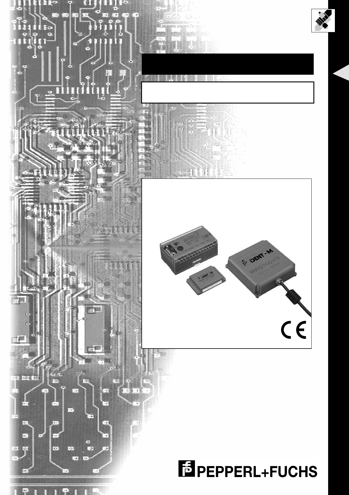
Ident-M System V
Microwave Identification
System
With regard to the supply of products, the current issue of the following document is applicable:
The General Terms of Delivery for Products and Services of the Electrical Industry, as published by
the Central Association of the "Elektrotechnik und Elektroindustrie (ZVEI) e.V.v",
including the supplementary clause "Extended reservation of title".
We at Pepperl+Fuchs recognise a duty to make a contribution to the future.
For this reason, this printed matter is produced on paper bleached without the use of chlorine.

IDENT-M System V
List of Contents
Date of issue 03.05.2001
1
Subject to reasonable modifications due to technical advances. Copyright Pepperl+Fuchs, Printed in Germany
Pepperl+Fuchs Group • Tel.: Germany (06 21) 7 76-0 • USA (330) 4 25 35 55 • Singapore 7 79 90 91 • Internet http://www.pepperl-fuchs.com
List of Contents
1 Declaration of Conformity .......................................................................5
2 General Information .................................................................................6
2.1 Symbols Used ......................................................................................................... 6
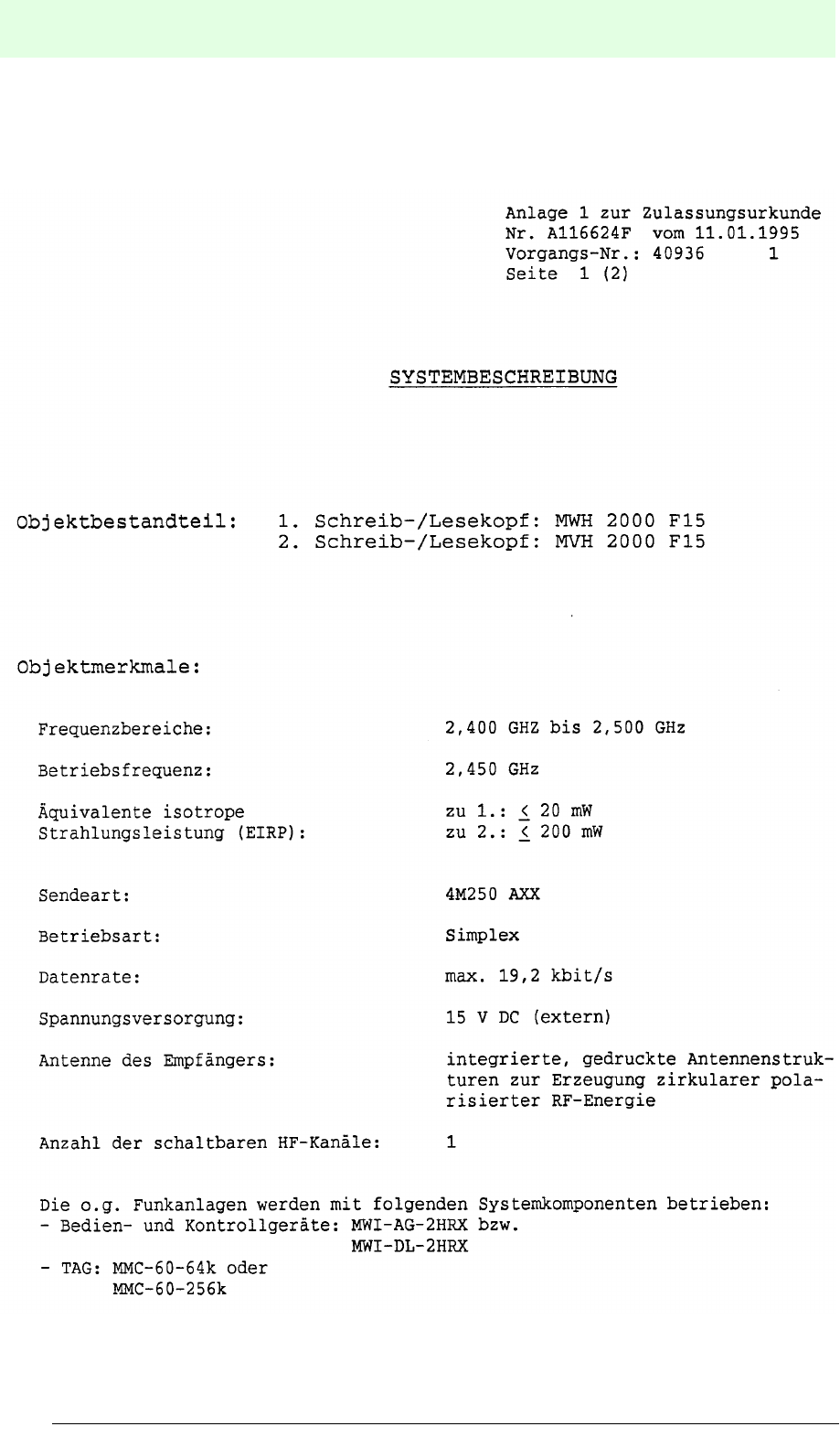
2.2 Approval Certificate ............................................................................................... 7
2.3 Declaration of Conformity ...................................................................................... 8
3 Safety ........................................................................................................9
3.1 Intended Use ........................................................................................................... 9
3.2 General Safety Instructions ................................................................................... 9
3.3 Functional Integrity/Functional Monitoring ....................................................... 10
4 Product Description ...............................................................................12
4.1 System Structure .................................................................................................. 12
4.2 Components ......................................................................................................... 16
4.2.1 MVI-D2-2HRX Control Interface Unit ...................................................................... 16
4.2.2 Read/Write Heads MVH500-F15/MVH2000-F15/MVH5000-F50 ........................... 19
4.2.3 Data Carriers MVC-60-64K/MVC-60-256K/MVC-60B-64K ..................................... 20
4.2.4 Read/Write Head Extension Cable ......................................................................... 21
5 Installation ..............................................................................................22
5.1 Storage and Transportation ................................................................................. 22
5.2 Unpacking ............................................................................................................. 22
5.3 Ambient Conditions .............................................................................................. 22
5.4 Selection of the Mounting Location ................................................................... 24
5.4.1 Positional Relation .................................................................................................. 24
5.4.2 Influence of Obstacles ............................................................................................ 26
5.4.3 Influence of Liquids ................................................................................................. 29
5.4.4 Influence of Metallic Objects ................................................................................... 30
5.4.5 Mounting Distance .................................................................................................. 34
5.4.6 Rate of Motion of the Data Carrier .......................................................................... 36
5.5 Mounting of Components ................................................................................... 39
5.5.1 MVI-D2-2HRX Control Interface Unit ...................................................................... 39
5.5.2 Read/Write Heads .................................................................................................. 41
5.5.3 Data Carrier ............................................................................................................ 42
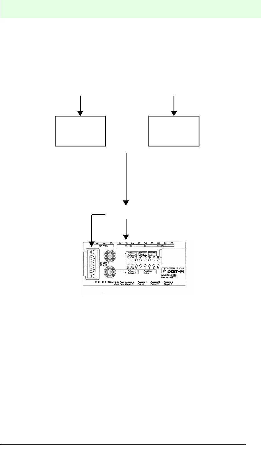
5.6 Connections of the MVI-D2-2HRX Control Interface Unit ................................ 44
5.6.1 Overview ................................................................................................................. 44
5.6.2 Connection of the MVI-D2-2HRX Control Interface Unit ......................................... 45
5.6.3 Connecting the MVI-D2-2HRX Control Interface Unit to a Host Controller ............. 47
5.6.4 Connection to the Trigger Inputs ............................................................................ 49
5.6.5 Connection of the Outputs ...................................................................................... 49
5.6.6 Connection of the Power Supply ............................................................................ 51

IDENT-M System V
List of Contents
Date of issue 03.05.2001
2
Subject to reasonable modifications due to technical advances. Copyright Pepperl+Fuchs, Printed in Germany
Pepperl+Fuchs Group • Tel.: Germany (06 21) 7 76-0 • USA (330) 4 25 35 55 • Singapore 7 79 90 91 • Internet http://www.pepperl-fuchs.com
5.7 Dismantling, Packing and Disposal ....................................................................52
6 Commissioning ...................................................................................... 53
6.1 Check List ..............................................................................................................53
6.2 Adjusting the Switches on the MVI-D2-2HRX Control Interface Unit ...............53
7 Communication Systems ...................................................................... 56
7.1 Overview ................................................................................................................56
7.1.1 Communication Startup System .............................................................................56
7.1.2 Response Return System .......................................................................................58
7.2 Occasional Execution System .............................................................................59
7.2.1 Occasional Execution System + Auto Response System .......................................59
7.2.2 Occasional Execution System + Response Request System .................................61
7.3 Command Stay System ....................................................................................... 64
7.3.1 Command Stay System + Auto Response System .................................................64
7.3.2 Command Stay System + Response Request System ...........................................66
7.4 Command Register System .................................................................................69
7.4.1 Command Register System + Auto Response System ..........................................70
7.4.2 Command Register System + Response Request System ....................................74
7.5 Read/Write Head Scan System ........................................................................... 78
7.5.1 Read/Write Head System + Auto Response System ..............................................79
7.5.2 Read/Write Head System + Response Request System ........................................82
7.5.3 Connection Example ...............................................................................................85
7.6 Simultaneous Processing of Commands ...........................................................87
7.6.1 With One Read/Write Head ....................................................................................87
7.6.2 With Two Different Read/Write Heads ....................................................................89
7.6.3 Description ..............................................................................................................91
8 Transmission Procedure ....................................................................... 92
8.1 Overview ................................................................................................................92
8.1.1 Verification ..............................................................................................................96
8.1.2 Copy ........................................................................................................................96
8.1.3 Block Check ............................................................................................................96
8.1.4 Self-Diagnosis of the Data Carrier ..........................................................................97
8.1.5 ROM Check ............................................................................................................97
8.1.6 RAM Check .............................................................................................................97
8.1.7 Checking the Battery Life of a Data Carrier ............................................................97
8.1.8 Self-diagnosis of MVI-D2-2HRX .............................................................................97
8.2 Output Instructions .............................................................................................. 98
8.2.1 Example for the Use of Output 0 for a Normal End ................................................98
8.2.2 Example for the Use of Output 1 as an Error Output ............................................100
8.3 Memory of the Control Interface Unit ............................................................... 107

IDENT-M System V
List of Contents
Date of issue 03.05.2001
3
Subject to reasonable modifications due to technical advances. Copyright Pepperl+Fuchs, Printed in Germany
Pepperl+Fuchs Group • Tel.: Germany (06 21) 7 76-0 • USA (330) 4 25 35 55 • Singapore 7 79 90 91 • Internet http://www.pepperl-fuchs.com
9 Commands ............................................................................................120
9.1 Common Code .................................................................................................... 120
9.2 Instruction Format ............................................................................................. 121
9.2.1 Standard Format ................................................................................................... 121
9.2.2 Setting the Read/Write Station Number ................................................................ 122
9.2.3 Check Sum ........................................................................................................... 123
9.2.4 Allocation of the Read/Write Head Scan System ................................................. 124
9.2.5 Accessing a Specific Read/Write Head of a Specific Station ............................... 125
9.3 Command Sets of the Transmission Systems ................................................ 126
9.3.1 Occasional Execution System + Auto Response System .................................... 126
9.3.2 Occasional Execution System + Response Request System .............................. 127
9.3.3 Command Stay System + Auto Response System .............................................. 128
9.3.4 Command Stay System + Response Request System ........................................ 129
9.3.5 Command Register System + Auto Response System ........................................ 130
9.3.6 Command Register System + Response Request System .................................. 131
9.3.7 Read/Write Head System + Auto Response System ........................................... 132
9.3.8 Read/Write Head Scan System + Response Request System ............................ 133
9.4 Commands and End Messages ........................................................................ 134
9.4.1 General Format ..................................................................................................... 134
9.4.2 General Commands .............................................................................................. 134
9.4.3 Overview of Commands ....................................................................................... 144
9.4.4 File Description of All Commands ......................................................................... 146
9.4.5 Example for Application of the “Single Read” Mode ............................................. 173
9.4.6 Example for the Use of the “Auto Read” Mode with
Unlimited Data Carrier Detection Time.................................................................. 175
10 Fault Diagnostics .................................................................................178
10.1 Trouble Shooting ................................................................................................ 178
10.2 Error Code ........................................................................................................... 179
10.3 Error Information ............................................................................................... 183
10.4 Battery Voltage Low Alarm ............................................................................... 185
11 Technical Data ......................................................................................186
11.1 Lifetime of the Data Carrier's Battery .............................................................. 190
12 Appendix ...............................................................................................193
12.1 ASCII (JIS) Code Table ....................................................................................... 193
12.1.1 Binary/Hexadecimal Table .................................................................................... 193
12.1.2 Octal Table ........................................................................................................... 193
12.1.3 Extension of the Read/Write Head Cable ............................................................. 194

IDENT-M System V
List of Contents
Date of issue 03.05.2001
4
Subject to reasonable modifications due to technical advances. Copyright Pepperl+Fuchs, Printed in Germany
Pepperl+Fuchs Group • Tel.: Germany (06 21) 7 76-0 • USA (330) 4 25 35 55 • Singapore 7 79 90 91 • Internet http://www.pepperl-fuchs.com

IDENT-M System V
Declaration of Conformity
Date of issue 03.05.2001
5
Subject to reasonable modifications due to technical advances. Copyright Pepperl+Fuchs, Printed in Germany
Pepperl+Fuchs Group • Tel.: Germany (06 21) 7 76-0 • USA (330) 4 25 35 55 • Singapore 7 79 90 91 • Internet http://www.pepperl-fuchs.com
1 Declaration of Conformity
The devices of the microwave identification system were developed and
manufactured in accordance with the European standards and directives.
Pepperl+Fuchs GmbH, the manufacturer of the product in D-68301 Mannheim, has a
certificated quality assurance system in accordance with ISO 9001.
The corresponding declaration of conformity can be requested from the
manufacturer.
ISO
9001

IDENT-M System V
General Information
Date of issue 03.05.2001
6
Subject to reasonable modifications due to technical advances. Copyright Pepperl+Fuchs, Printed in Germany
Pepperl+Fuchs Group • Tel.: Germany (06 21) 7 76-0 • USA (330) 4 25 35 55 • Singapore 7 79 90 91 • Internet http://www.pepperl-fuchs.com
2 General Information
2.1 Symbols Used
This symbol warns of possible danger.
Failure to heed this warning can lead to personal injury or death and/or
damage to or destruction of equipment.
This symbol warns the user of a possible failure.
If the instruction given in this warning is not heeded, the device and any
plant or systems connected to it could develop a fault or even fail
completely.
This symbol alerts the user of an important hint.
IDENT-M System V
General Information
Date of issue 03.05.2001
7
Subject to reasonable modifications due to technical advances. Copyright Pepperl+Fuchs, Printed in Germany
Pepperl+Fuchs Group • Tel.: Germany (06 21) 7 76-0 • USA (330) 4 25 35 55 • Singapore 7 79 90 91 • Internet http://www.pepperl-fuchs.com
2.2 Approval Certificate
IDENT-M System V
General Information
Date of issue 03.05.2001
8
Subject to reasonable modifications due to technical advances. Copyright Pepperl+Fuchs, Printed in Germany
Pepperl+Fuchs Group • Tel.: Germany (06 21) 7 76-0 • USA (330) 4 25 35 55 • Singapore 7 79 90 91 • Internet http://www.pepperl-fuchs.com
2.3 Declaration of Conformity

IDENT-M System V
Safety
Date of issue 03.05.2001
9
Subject to reasonable modifications due to technical advances. Copyright Pepperl+Fuchs, Printed in Germany
Pepperl+Fuchs Group • Tel.: Germany (06 21) 7 76-0 • USA (330) 4 25 35 55 • Singapore 7 79 90 91 • Internet http://www.pepperl-fuchs.com
3 Safety
3.1 Intended Use
3.2 General Safety Instructions
The protection of operating personnel and plant is not guaranteed if the
equipment is used for a purpose for which is was not intended.
The devices must only be operated by authorised specialist personnel
in accordance with these operating instructions.
The microwave radiation produced by the device is less than 50 mW
(EIRP - Equivalent Isotropic Radio Power) which is noticeably below the
approved values in accordance with the BAPT 211 ZV 037/2050, April
1997 edition.
However, note that the device emits electromagnetic radiation during
operation and therefore cannot be used in some environments.
Especially for persons using hearing aids or pacemakers it is urgently
recommended to consult a doctor, before putting the device into
operation.
Safety and correct functioning of the device cannot be guaranteed if
operated in any way other than that described in this handbook.
The connection of the device and maintenance work under power must
only be carried out by qualified electrotechnical personnel.
In the case that a failure cannot be repaired, the device must be taken
out of operation and protected against inadvertently being put back into
operation.
Repairs must only be carried out by the manufacturer. Additions or
modifications to the equipment are not permitted. They render the
warranty void.
The operator is responsible for complying with local safety regulations.
IDENT-M System V
Safety
Date of issue 03.05.2001
10
Subject to reasonable modifications due to technical advances. Copyright Pepperl+Fuchs, Printed in Germany
Pepperl+Fuchs Group • Tel.: Germany (06 21) 7 76-0 • USA (330) 4 25 35 55 • Singapore 7 79 90 91 • Internet http://www.pepperl-fuchs.com
3.3 Functional Integrity/Functional Monitoring
IDENT-M System V
Safety
Date of issue 03.05.2001
11
Subject to reasonable modifications due to technical advances. Copyright Pepperl+Fuchs, Printed in Germany
Pepperl+Fuchs Group • Tel.: Germany (06 21) 7 76-0 • USA (330) 4 25 35 55 • Singapore 7 79 90 91 • Internet http://www.pepperl-fuchs.com
IDENT-M System V
Product Description
Date of issue 03.05.2001
12
Subject to reasonable modifications due to technical advances. Copyright Pepperl+Fuchs, Printed in Germany
Pepperl+Fuchs Group • Tel.: Germany (06 21) 7 76-0 • USA (330) 4 25 35 55 • Singapore 7 79 90 91 • Internet http://www.pepperl-fuchs.com
4 Product Description
4.1 System Structure
The Microwave ID system IDENT-M consists of a control unit, read/write heads, and
data carriers. The IDENT-M system sends and receives data between a host
controller (personal computer) and data carriers. For communication between the
read/write head and data carriers the IDENT-M system uses microwaves.
Data carrier
Memory
Control interface unit
Host
controller
Control unit
Communication
function
Microwave
communication
Communication
function
MVI-D2-2HRX
MVH500-F15/
MVH2000-F15/
MVC-60-64K/
MVC-60-256/
Read/write head
MVH5000-F50
MVC-60B-64K
IDENT-M System V
Product Description
Date of issue 03.05.2001
13
Subject to reasonable modifications due to technical advances. Copyright Pepperl+Fuchs, Printed in Germany
Pepperl+Fuchs Group • Tel.: Germany (06 21) 7 76-0 • USA (330) 4 25 35 55 • Singapore 7 79 90 91 • Internet http://www.pepperl-fuchs.com
Multiple control units at one host controller:
(RS 422 interface)
MVI-D2-2HRX
Station number “0”
MVI-D2-2HRX
Station number “1”
MVI-D2-2HRX
Station number “F”
Host controller
(e.g. personal computer)
* When connected via the
RS 422 interface, a
maximum of 16 MVI-D2-
2HRX control interface units
can be coupled together.
Max. transmission distance
is 1,000 m.
RS 422
RS 422*
IDENT-M System V
Product Description
Date of issue 03.05.2001
14
Subject to reasonable modifications due to technical advances. Copyright Pepperl+Fuchs, Printed in Germany
Pepperl+Fuchs Group • Tel.: Germany (06 21) 7 76-0 • USA (330) 4 25 35 55 • Singapore 7 79 90 91 • Internet http://www.pepperl-fuchs.com
One control interface unit at one host controller:
(RS 232C interface)
MVI-D2-2HRX
Host controller
(e.g. personal computer)
*Max. transmission distance
for a connection of an MVI-
D2-2HRX control interface
unit via the RS 232C
interface is 15 m.
optionally
RS 232*
IDENT-M System V
Product Description
Date of issue 03.05.2001
15
Subject to reasonable modifications due to technical advances. Copyright Pepperl+Fuchs, Printed in Germany
Pepperl+Fuchs Group • Tel.: Germany (06 21) 7 76-0 • USA (330) 4 25 35 55 • Singapore 7 79 90 91 • Internet http://www.pepperl-fuchs.com
Control interface unit at one bus coupler:
(RS 422 interface)
MVI-D2-2HRX
Bus coupler
MVG-KFD2-B5
Bus coupler
MVG-KFD2-B6
or
INTERBUS PROFIBUS
optionally
RS 422
IDENT-M System V
Product Description
Date of issue 03.05.2001
16
Subject to reasonable modifications due to technical advances. Copyright Pepperl+Fuchs, Printed in Germany
Pepperl+Fuchs Group • Tel.: Germany (06 21) 7 76-0 • USA (330) 4 25 35 55 • Singapore 7 79 90 91 • Internet http://www.pepperl-fuchs.com
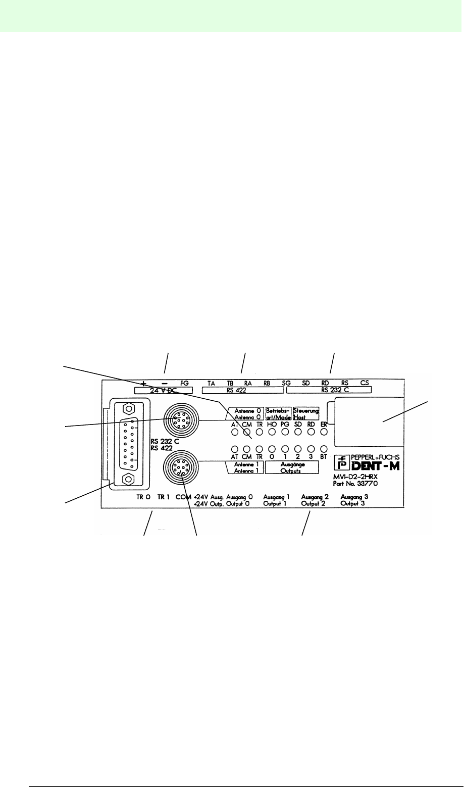
4.2 Components
4.2.1 MVI-D2-2HRX Control Interface Unit
The control interface unit controls the data transfer between the host controller and
the data carriers. The control interface unit receives instructions from the host
controller via serial interface RS 232C or RS 422.
• A maximum of 16 MVI-D2-2HRX control interface units can be controlled via
interface.
• For data transmission between host controller and MVI-D2-2HRX either
RS 232C or RS 422 interface is used. A terminal block or a connector system is
used for connection.
• The read/write head automatically detects the existence of a data carrier and can
send and receive data.
• The read/write head can communicate with a specific data carrier.
• The data transmission rate between the MVI-D2-2HRX, the read/write head
(MVH500-F15/MVH2000-F15/MVH5000-F50) and the data carrier (MVC-60-
64K) is 76.8 kbit/s.
12 3
4
567
8
9
10

IDENT-M System V
Product Description
Date of issue 03.05.2001
17
Subject to reasonable modifications due to technical advances. Copyright Pepperl+Fuchs, Printed in Germany
Pepperl+Fuchs Group • Tel.: Germany (06 21) 7 76-0 • USA (330) 4 25 35 55 • Singapore 7 79 90 91 • Internet http://www.pepperl-fuchs.com
No. Designation Function
1Power supply Connection of the DC 24 V power supply
2Host controller
interface RS 232C interface terminals
3Interface Terminals for RS 422 interface 1
4
Switch
(under the
cover)
SW 1
Setting the data length, parity, stop bit, connector type, data
transmission standard, selection between 2-wire connection, 4-wire
connection and high speed mode.
SW 2 Setting the station number.
SW 3 Setting the communication rate between host controller and MVI-D2-
2HRX.
SW 4 Setting the terminal resistance.
5Outputs
6Connector 1 Connector for read/write head 1
7Trigger inputs
8Interface for host
controller Connector for RS 232C and RS 422 interface 2
9Connector 0 Connector for read/write head 0
10 Status indicator Indicates the operating status (see next page).

IDENT-M System V
Product Description
Date of issue 03.05.2001
18
Subject to reasonable modifications due to technical advances. Copyright Pepperl+Fuchs, Printed in Germany
Pepperl+Fuchs Group • Tel.: Germany (06 21) 7 76-0 • USA (330) 4 25 35 55 • Singapore 7 79 90 91 • Internet http://www.pepperl-fuchs.com
Designation of LED Contents
AT (Antenne 0) Lights when a read/write head is connected to the 0/1 connector.
(Antenna 1)
CM
(Antenne 0) Flashes when a read/write head is connected to the 0/1 connector,
and when data transmissions take place between read/write head
and a data carrier.
(Antenna 1)
TR (Antenne 0) Lights when a trigger signal for the read/write head 0/1 is due to be
sent.
(Antenna 1)
HO (Mode) Lights when communication with a host controller is possible.
PG (Mode) Reserved.
SD (Host) Flashes when the MVI-D2-2HRX sends data to the host controller.
RD (Host) Flashes when the MVI-D2-2HRX receives data from the host
controller.
ER
Lights when a transmission error occurs in communication with the
host controller and goes OFF when the control unit receives a new
command from the host controller.
Lights when an error occurs while executing a command, and
goes OFF when the control interface unit receives the reset
command from the host controller.
0, 1, 2, 3 (Outputs)
Lights when the output is turned ON by instruction from the host
controller (relay is switched). (Goes OFF when the relay is in the
OFF position).
BT Lights when the battery voltage of the integrated battery in the
MVI-D2-2HRX is too low.
AT CM TR HO PG SD RD ER
AT CM TR 0 1 2 3 BT
Antenne 1
Antenna 1
Antenne 0
Antenna 0
Steuerung
Host
Ausgänge
Outputs
Status indicator
Betriebs-
art/Mode
IDENT-M System V
Product Description
Date of issue 03.05.2001
19
Subject to reasonable modifications due to technical advances. Copyright Pepperl+Fuchs, Printed in Germany
Pepperl+Fuchs Group • Tel.: Germany (06 21) 7 76-0 • USA (330) 4 25 35 55 • Singapore 7 79 90 91 • Internet http://www.pepperl-fuchs.com
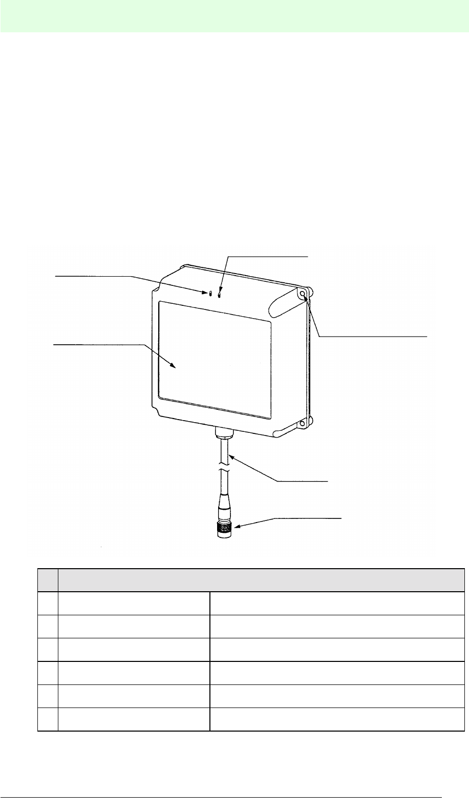
4.2.2 Read/Write Heads MVH500-F15/MVH2000-F15/MVH5000-F50
The read/write head, which is controlled by the MVI-D2-2HRX, sends and receives
data from data carriers, as long as the data carriers are located inside the
transmission area. The read/write head transmits the received data to the
MVI-D2-2HRX.
• For communication with the data carrier three models of read/write heads are
available: MVH500-F15 for medium distance, MVH2000-F15 for long distance,
MVH5000-F50 for extra long distance.
• 2.45 GHz microwaves are used for data transmission between read/write heads
and data carriers. Since the read/write heads operate with circularly polarised
microwaves, transmission interference due to metal reflection is minimised.
No. Designation
1Status indicator TX
2Operation indicator OK
3Mounting holes Mounting hole Ø4.5 mm
4Read/write head cable
5Read/write head connector
6Front Microwave communication
1
2
3
4
5
6
IDENT-M System V
Product Description
Date of issue 03.05.2001
20
Subject to reasonable modifications due to technical advances. Copyright Pepperl+Fuchs, Printed in Germany
Pepperl+Fuchs Group • Tel.: Germany (06 21) 7 76-0 • USA (330) 4 25 35 55 • Singapore 7 79 90 91 • Internet http://www.pepperl-fuchs.com
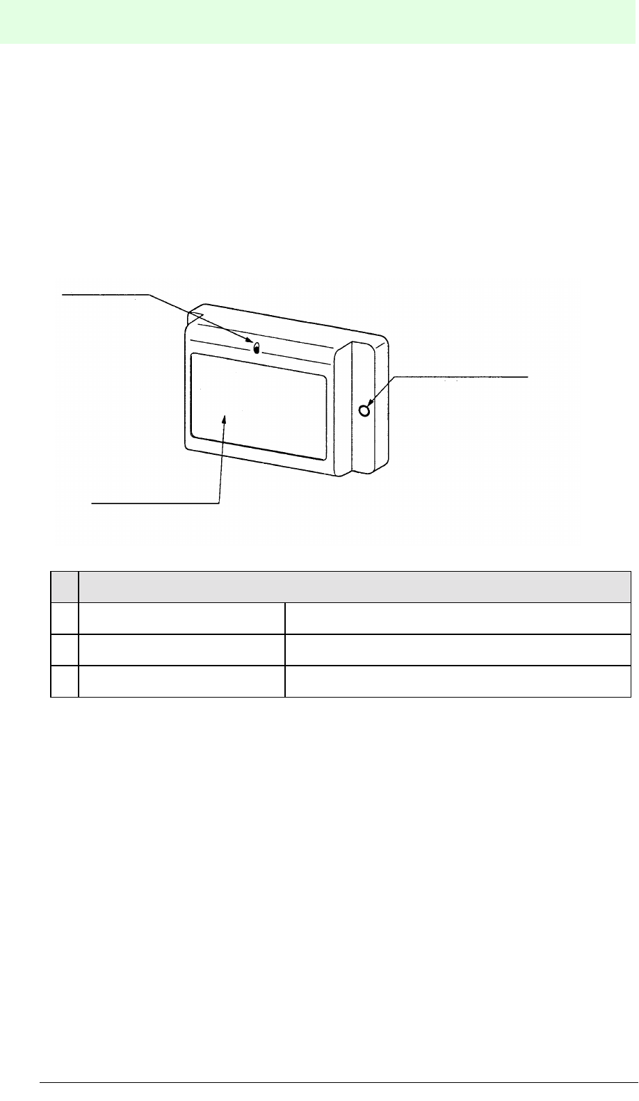
4.2.3 Data Carriers MVC-60-64K/MVC-60-256K/MVC-60B-64K
The data carrier stores data from the read/write head inside the integrated memory or
sends the data back to the read/write head.
• Installation allowance of the data carrier is ± 45° in the horizontal and the vertical
directions and any position in the direction of rotation.
• Three types of data carriers with different memory capacity are available: the 8
kByte MVC-60-64K type, the 32 kByte MVC-60-256K type and the MVC-60B-64K
type with replaceable battery.
No. Designation
1Operation indicator OK
2Mounting holes Mounting hole Ø4.5 mm
3Front Microwave communication
1
2
3
IDENT-M System V
Product Description
Date of issue 03.05.2001
21
Subject to reasonable modifications due to technical advances. Copyright Pepperl+Fuchs, Printed in Germany
Pepperl+Fuchs Group • Tel.: Germany (06 21) 7 76-0 • USA (330) 4 25 35 55 • Singapore 7 79 90 91 • Internet http://www.pepperl-fuchs.com
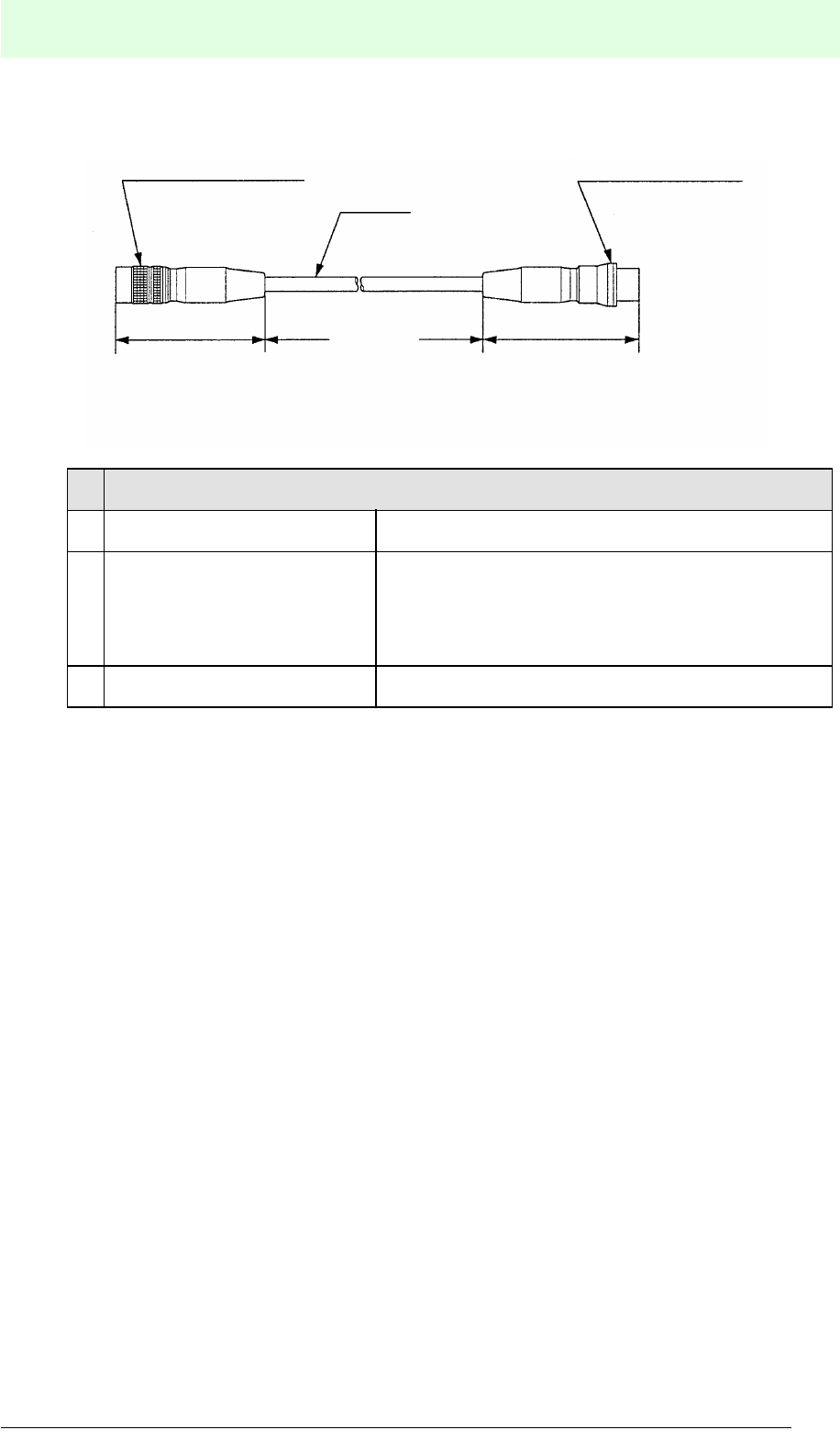
4.2.4 Read/Write Head Extension Cable
See “Extension of the Read/Write Head Cable” on page 194.
No. Designation
1Connector To the MVI-D2-2HRX control interface unit
2Cable
Ready made-up cable lengths:
MVK-5: 5 m
MVK-10: 10 m
MVK-20: 20 m
MVK-30: 30 m
3Jack To the read/write head
1
2
Length
45 mm 45 mm
3

IDENT-M System V
Installation
Date of issue 03.05.2001
22
Subject to reasonable modifications due to technical advances. Copyright Pepperl+Fuchs, Printed in Germany
Pepperl+Fuchs Group • Tel.: Germany (06 21) 7 76-0 • USA (330) 4 25 35 55 • Singapore 7 79 90 91 • Internet http://www.pepperl-fuchs.com
5Installation
5.1 Storage and Transportation
The device should be well packed for transportation and storage, so that protection is
provided against shock and dampness. Optimum protection is afforded by the original
packaging. In addition, the permissible ambient conditions must prevail (see chapter
5.3 “Ambient Conditions”).
5.2 Unpacking
Inspect the contents for damage. In the event of damage, the postal service or goods
transport service should be informed and the supplier notified.
Inspect the contents of the delivery package against your order and the delivery
documents:
• Quantity delivered
• Device type and version in accordance with the type plate
• Accessories
• Manual/manuals
Retain the original packaging in case the items have to be stored or further
transported at a later date.
Please address any queries to Pepperl+Fuchs GmbH.
5.3 Ambient Conditions
Installation of Control Interface Unit
Do not install the control unit on the following locations:
• Locations exposed to direct sunlight or an ambient temperature falling below or
exceeding 0 °C ... 55 °C.
• Locations where relative humidity exceeds or falls short of 35 % ... 90 %, or dew
condensation occurs due to rapid temperature variation.
• Locations where corrosive vapour or inflammable gas is present.
• Locations where vibration or shock is directly transferred to the control interface
unit.
Installation Read/Write Head and Data Carrier
Be sure to meet all the requirements described in chapter 5.4 “Selection of the
Mounting Location” and chapter 5.5 “Mounting of Components”.
Static Charge
In extremely dry conditions, the human body may be charged statically. This static
charge may damage or destroy parts mounted on PC boards inside the control unit.
Prior to handling the control unit, touch a metal object which is grounded to discharge
static electricity.

IDENT-M System V
Installation
Date of issue 03.05.2001
23
Subject to reasonable modifications due to technical advances. Copyright Pepperl+Fuchs, Printed in Germany
Pepperl+Fuchs Group • Tel.: Germany (06 21) 7 76-0 • USA (330) 4 25 35 55 • Singapore 7 79 90 91 • Internet http://www.pepperl-fuchs.com
Usage
The data carrier has a built-in lithium battery for data backup. The battery has a limited
life span (MVC-60-64K and MVC-60-256K). Replace the data carrier with a new one
before the batteries are exhausted. The battery of the MVC-60B-64K must be
replaced in good time. Delay in replacement may cause malfunction of the data
carrier. Battery life can be checked by referring to the production year, -month,
storage time, operation time, and battery use ration by means of the program.
Cleaning
To clean the control interface unit, use a dry, soft cloth. Do not use any volatile solvent
such as alcohol, thinner, freon, or even a wet cloth for cleaning, as this may cause a
deformation or color change.
Storage
Since the control interface unit and the data carrier have lithium batteries inside, do
not put them into fire. The lithium battery may explode or burn which is quite
dangerous.
Do not lay the control interface unit face-down or put any weight on it.
IDENT-M System V
Installation
Date of issue 03.05.2001
24
Subject to reasonable modifications due to technical advances. Copyright Pepperl+Fuchs, Printed in Germany
Pepperl+Fuchs Group • Tel.: Germany (06 21) 7 76-0 • USA (330) 4 25 35 55 • Singapore 7 79 90 91 • Internet http://www.pepperl-fuchs.com
5.4 Selection of the Mounting Location
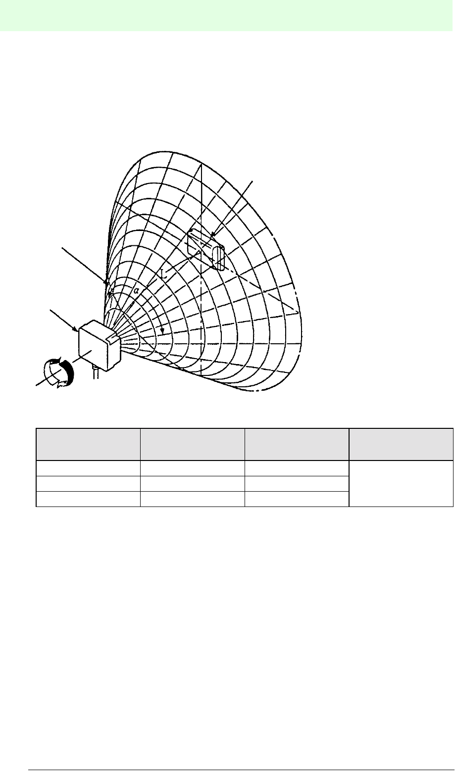
5.4.1 Positional Relation
On condition that there is no nearby object, the conical area shown in the illustration
below represents the available transmission area (transmission range).
Figure 5.1: Transmission area of the read/write head
Read/write head L a Applicable data
carriers
MVH500-F15 500 mm 60° MVC-60-64K
MVC-60-256K
MVC-60B-64K
MVH2000-F15 200 mm ... 2,000 mm 60°
MVH5000-F50 5,000 mm 60°
1
2
3
360°
1 Data carrier
2 Data transmission
area
3 Read/write head
IDENT-M System V
Installation
Date of issue 03.05.2001
25
Subject to reasonable modifications due to technical advances. Copyright Pepperl+Fuchs, Printed in Germany
Pepperl+Fuchs Group • Tel.: Germany (06 21) 7 76-0 • USA (330) 4 25 35 55 • Singapore 7 79 90 91 • Internet http://www.pepperl-fuchs.com
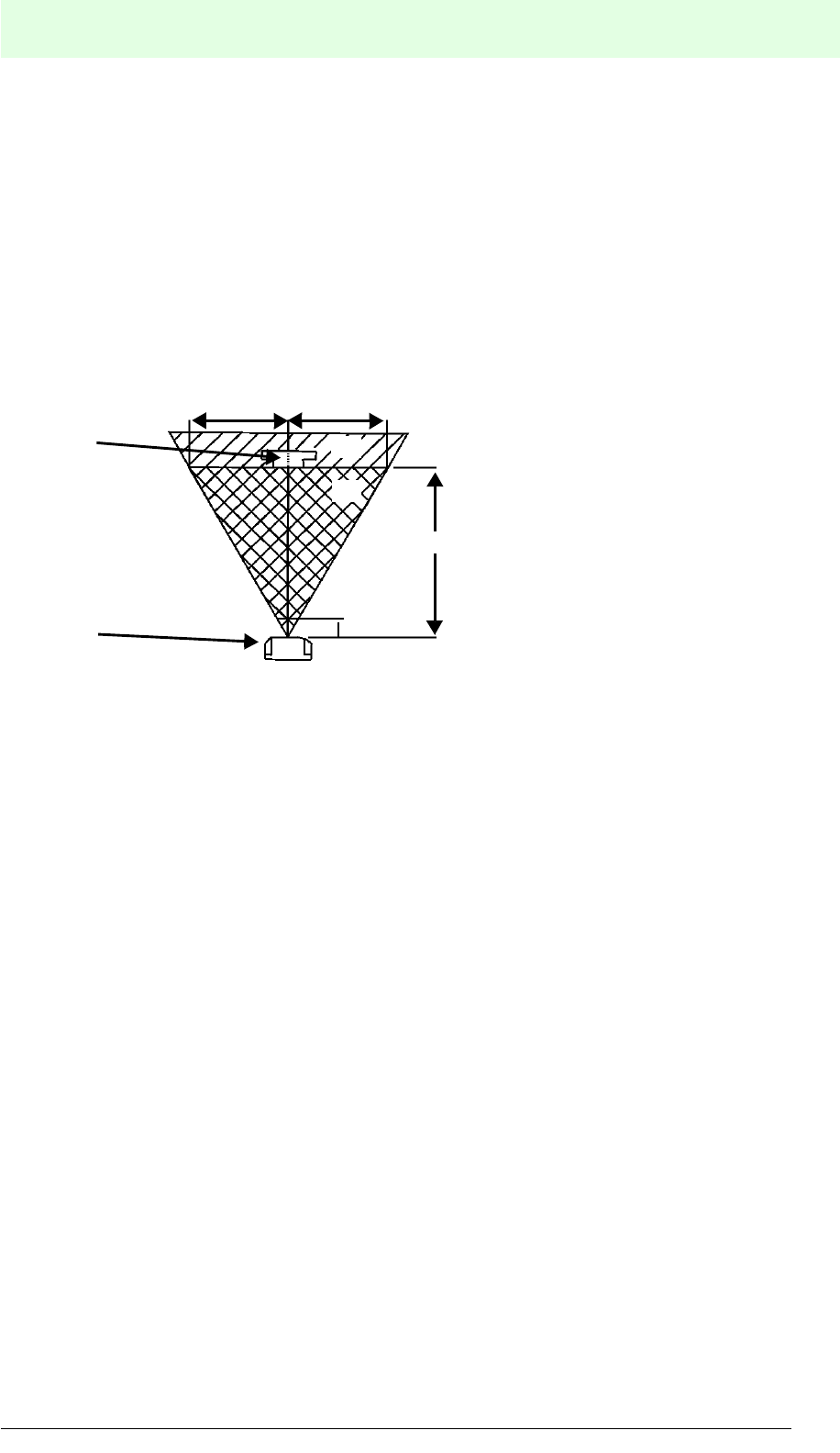
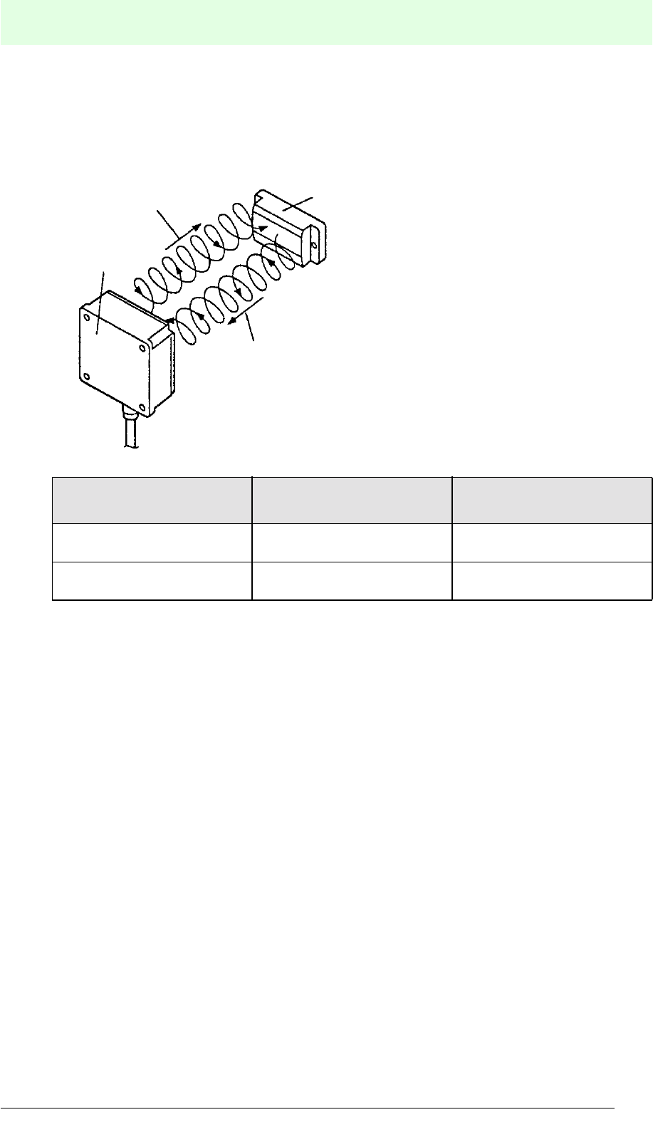
When the front angle of the data carrier and the front angle of the read/write head is
between 0° and 45°, the data carrier's transmission area is reduced accordingly.
When the data carrier is installed with a slant, reduce the distance between the read/
write head and data carrier as much as possible.
Communication in area A is possible. However, this area may suffer interference from
surroundings. Even in area B and near the area, existence of an object may change
the transmission area or make a data transmission between the read/write head and
the data carrier impossible within the recommended distance. For installation, first
carefully check the transmission availability in a field test.
Figure 5.2: Communication area of the read/write head
200 mm
2,000 mm
B
A
3
2
1
1 Data carrier
2 Read/write head
3 Pivoting angle 0°
IDENT-M System V
Installation
Date of issue 03.05.2001
26
Subject to reasonable modifications due to technical advances. Copyright Pepperl+Fuchs, Printed in Germany
Pepperl+Fuchs Group • Tel.: Germany (06 21) 7 76-0 • USA (330) 4 25 35 55 • Singapore 7 79 90 91 • Internet http://www.pepperl-fuchs.com
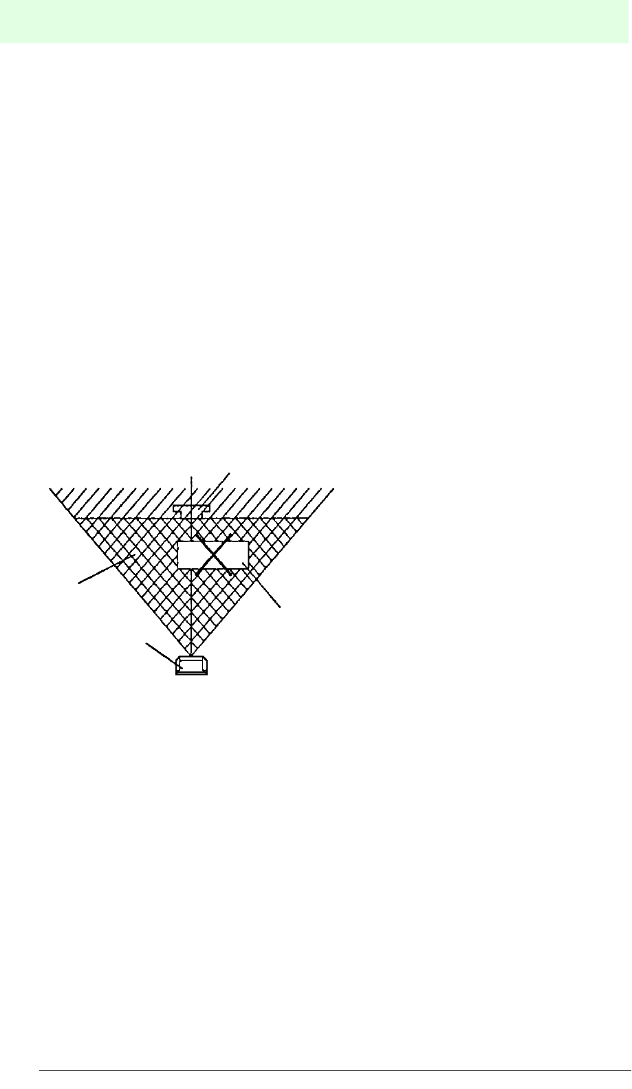
5.4.2 Influence of Obstacles
When transmitting data between the read/write head and the data carrier, remove any
reflective object (metal etc.) or dielectric object (human body or moist wooden
material) from the data transmission area. When such an object is within the
transmission area, (see figure 5.2) the transmission of microwaves may be interfered
and therefore a normal transmission would not be possible.
Microwaves are reflected when they impinge upon a reflective object and they may
be absorbed when they impinge upon a dielectric object.
A cover used to protect the read/write head or the data carrier should be made of
plastic with low dielectric properties (polyethylene fluoride etc.). In addition, it must be
ensured that the cover does not affect transmission in the current transmission
system arrangement.
When reflective objects (such as metallic objects) are located near the read/write
head or the data carrier, transmission errors may even occur within area “A” see
figure 5.2. Please check the constant data transmission between the read/write head
and the data carrier by simulating and testing the conditions of the current system
arrangement.
1 Data carrier
2 Read/write head
3 Data transmission
area
4 Reflective or
dielectric object
1
2
3
4
IDENT-M System V
Installation
Date of issue 03.05.2001
27
Subject to reasonable modifications due to technical advances. Copyright Pepperl+Fuchs, Printed in Germany
Pepperl+Fuchs Group • Tel.: Germany (06 21) 7 76-0 • USA (330) 4 25 35 55 • Singapore 7 79 90 91 • Internet http://www.pepperl-fuchs.com
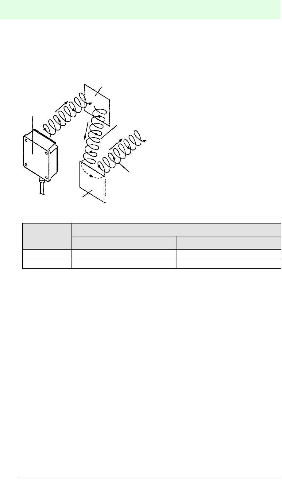
The IDENT-M microwave identification system uses circular polarised microwaves
which advance while rotating, and thus lower the influence of a reflective object or an
adjacent system.
Transmission function Microwave from the read/
write head
Microwave from the data
carrier
Read Clockwise rotation of
polarised wave Clockwise rotation
Write Counter-clockwise rotation of
polarised wave –
1
2
3
4
1 Data carrier
2 Read/write head
3 Microwave from the
read/write head
4 Microwave from the
data carrier
IDENT-M System V
Installation
Date of issue 03.05.2001
28
Subject to reasonable modifications due to technical advances. Copyright Pepperl+Fuchs, Printed in Germany
Pepperl+Fuchs Group • Tel.: Germany (06 21) 7 76-0 • USA (330) 4 25 35 55 • Singapore 7 79 90 91 • Internet http://www.pepperl-fuchs.com
When a microwave strikes a reflecting object, it is reflected like a light beam on a
mirror. Within this process, the rotation of the polarised wave reverses its sense of
direction.
• The unique or odd times reflected wave does not influence the data transmission,
since the rotation direction is in reverse sense.
• The even times reflected wave weakens, since the distance between the read/
write head and the data carrier is longer than the direct wave from the read/write
head, so that the data carrier can eliminate the reflected wave within its receive
circuit. A transfer error occurs, when the data carrier cannot eliminate the
reflected wave in its receive circuit, since the intensity of the reflected wave
equals the intensity of the direct wave.
Communica-
tion function
Microwave reflected by a reflective object
First (odd) reflected wave Second (even) reflected wave
Read Counter-clockwise rotation Clockwise rotation
Write Clockwise rotation Counter-clockwise rotation
1
2
2
3
4
1 Read/write head
2 Reflection object
3 First reflected wave
4 Second reflected
wave

IDENT-M System V
Installation
Date of issue 03.05.2001
29
Subject to reasonable modifications due to technical advances. Copyright Pepperl+Fuchs, Printed in Germany
Pepperl+Fuchs Group • Tel.: Germany (06 21) 7 76-0 • USA (330) 4 25 35 55 • Singapore 7 79 90 91 • Internet http://www.pepperl-fuchs.com
5.4.3 Influence of Liquids
(Rain, snow, coolants, cleaning liquids, human bodies)
Make sure that no water film forms between the data carrier and the read/write head,
while transmitting data to the data carrier.
Thermal Influence of Microwaves
• When microwaves are projected on water, water molecules are separated and
oscillated. Friction heat caused by colliding molecules increases the water
temperature.
• When there is a water film between the data carrier and the read/write head, radio
wave energy is converted into thermal energy and the radio wave attenuates.
Therefore, the available transmission distance is reduced.
Note: Oil is not activated by microwaves and therefore does not reduce the
available transmission distance.
• 70 % of the human body consists of water so that transmission is not possible,
when there is human body between the data carrier and the read/write head.
Reduction of the Actual Transmission Distance
• The available transmission distance is neither reduced by individual water-drops
on the data carrier or the read/write head surface nor by moistening the surfaces
with water.
• When the data carrier is dipped into water, or when there is a waterfall between
the data carrier and the read/write head, the maximum transmission distance
reduces according to the waterfall's thickness.
Influence of Rain and Snow
• The transmission distance is not influenced by rain or snowfall occuring between
the data carrier and the read/write head.
• When the data carrier or the read/write head are operated during heavy snowfall
or rain, a water film may form on them causing the transmission distance to
diminish.
• When the data carrier or the read/write head is covered with dry snow or snow
crystals, the molecules are not separated by microwaves and the radio waves can
pass through the snow. However, wet snow may attenuate radio waves and
reduce the transmission distance.
Water film
thickness None 1 mm 5 mm 10 mm 50 mm
MVH500-F15 2,000 mm 1,300 mm 300 mm 30 mm 5 mm
MVH2000-F15 4,000 mm 2,500 mm 700 mm 100 mm 10 mm

IDENT-M System V
Installation
Date of issue 03.05.2001
30
Subject to reasonable modifications due to technical advances. Copyright Pepperl+Fuchs, Printed in Germany
Pepperl+Fuchs Group • Tel.: Germany (06 21) 7 76-0 • USA (330) 4 25 35 55 • Singapore 7 79 90 91 • Internet http://www.pepperl-fuchs.com
Influence of Coolants
When using a water-soluble coolant for working processes, it must be ensured that
no coolant film forms between the data carrier and the read/write head during the
transmission process.
1. Install a valve, in order to stop the coolant supply during the transmission process.
2. Be careful to install the data carrier and the read/write head at a place where a
coolant film cannot form during transmission.
3. Use a device (a shade or a pail), to prevent the flow of coolant so that no coolant
film forms between the data carrier and the read/write head.
Influence of Cleaning Liquids
• When pallets or workpieces are cleaned, while installing the data carrier, it must
be ensured that no water film forms on the surfaces of the data carriers (vapours
caused by cleaning liquids do not affect the transmission).
• When installing a plastic protective cover on the front side of the data carrier, it
must be ensured that no cleaning liquid remains inside the cover plate.
5.4.4 Influence of Metallic Objects
(Conveyor belts, pallets, machines and workpieces)
Since radio waves reflected by metal objects close to the data carrier and the read/
write head come from different directions, the angle and the height of the read/write
head have to be adjusted so that transfer errors due to multiple transmission are
prevented.
Microwave Reflection of Metal Objects
• Microwaves are characteristically reflected by metallic objects. When a metallic
object is located close to the data carrier or the read/write head, the data carrier
receives direct radio waves from the read/write head as well as radio waves
reflected from metallic objects. When direct radio waves and reflected radio
waves arrive in reverse phase difference, these two radio waves cancel each
other out and the radio signal weakens. The same applies to radio waves from
the data carrier to the read/write head.
• When using a data carrier in a production line, metallic objects with complex
shapes may be near the data carrier and the read/write head. Therefore, they
receive reflected waves from different directions. In order to prevent this,
measures must be taken to screen the reflected waves.
IDENT-M System V
Installation
Date of issue 03.05.2001
31
Subject to reasonable modifications due to technical advances. Copyright Pepperl+Fuchs, Printed in Germany
Pepperl+Fuchs Group • Tel.: Germany (06 21) 7 76-0 • USA (330) 4 25 35 55 • Singapore 7 79 90 91 • Internet http://www.pepperl-fuchs.com
Presence of a Metallic Object with Complex Reflective Surface
The IDENT-M microwave identification system uses a circularly polarised wave
system and is also screened, to prevent the influence of metal reflection. Some
shapes of metal objects or their arrangement next to the data carrier and the read/
write head may cause the transmission not to function trouble-free. When direct or
double reflected waves reach the receiver with the same intensity, the radio signal
may be attenuated or changed.
Measures against Reflected Waves
Altering the read/write head installation angle changes the direction of the reflected
wave which superimposes the direct wave. In this way, it is possible to eliminate
transmission errors.
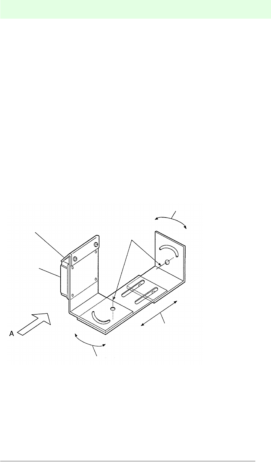
1. Planning the arrangement
Provide an angle adjustment function for the read/write head, thereby enabling it
to be adjusted to ±30° in up/down and left/right direction against the crossing point
of the read/write head central axis as well as the data carrier distance.
2. Adjusting the arrangement
Adjust the read/write head angle in order to minimise the transmission distance
between the data carrier and the read/write head.
1 Read/write head
2 Dust guard
3 Angle of rotation
4 Axis of rotation
5 Angle slide direction
1
2
3
3
4
5

IDENT-M System V
Installation
Date of issue 03.05.2001
32
Subject to reasonable modifications due to technical advances. Copyright Pepperl+Fuchs, Printed in Germany
Pepperl+Fuchs Group • Tel.: Germany (06 21) 7 76-0 • USA (330) 4 25 35 55 • Singapore 7 79 90 91 • Internet http://www.pepperl-fuchs.com
Sectional drawing “A”
* Be careful to observe the minimum distance, to protect the cable when it is moved.
Influence of Casting Dust (Cutting powder, slag)
When casting dust settles on the data carrier or on the read/write head, the radio
waves may attenuate thereby reducing the available transmission distance. When
using the data carriers and the read/write heads in a metal processing plant,
precautions must be taken to prevent cutting dust from settling on the devices.
Attenuation of Radio Waves due to Metal Dust, Oscillation of Metal Dust
• The microwave system uses 2.45 GHz radio waves. The 2.45 GHz radio wave
has a wave length of 122 mm and resonates with metallic objects, that have
approximately 1/2, 1/4 or 1/8 of this wave length. This may attenuate the radio
wave energy.
• When a metallic object with 10 mm length of side adheres to the data carrier or
the read/write head, the occuring resonance may cause the radio signal to
attenuate and the transmission distance to be reduced.
Reflection by Metal Dust
Large amounts of metal dust or sliced particles may reflect microwaves, attenuate the
radio signal and reduce the transmission distance.
>75 mm*
(*
IDENT-M System V
Installation
Date of issue 03.05.2001
33
Subject to reasonable modifications due to technical advances. Copyright Pepperl+Fuchs, Printed in Germany
Pepperl+Fuchs Group • Tel.: Germany (06 21) 7 76-0 • USA (330) 4 25 35 55 • Singapore 7 79 90 91 • Internet http://www.pepperl-fuchs.com
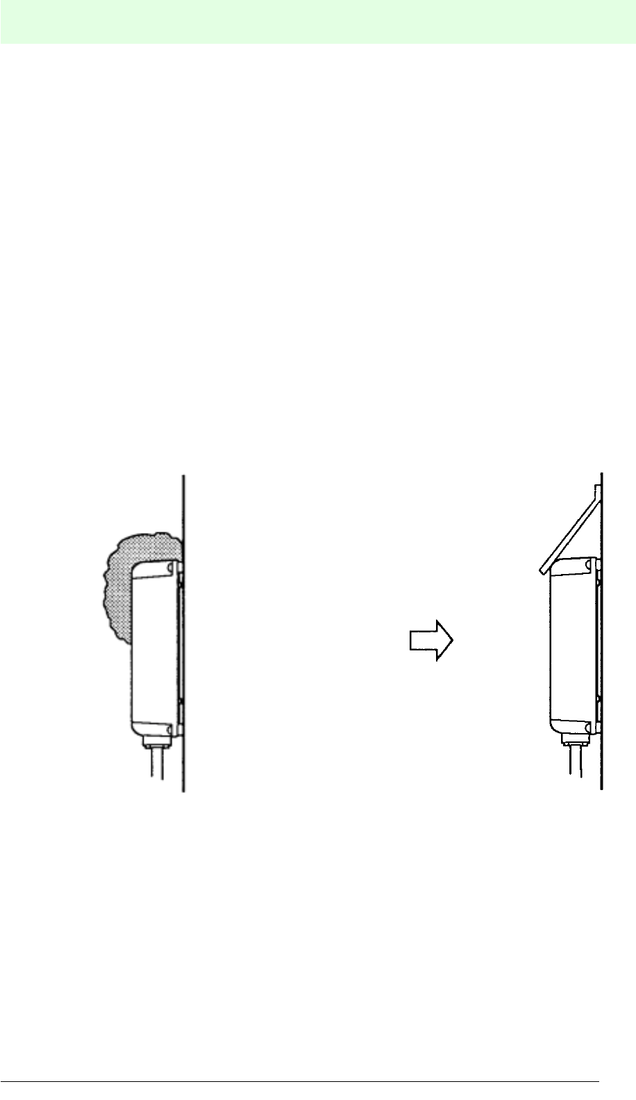
Settling of Cutting Dust during Cutting Procedures
1. When the data carrier or the read/write head is mounted vertically and its surface
is moist from coolant, fine metal dust may settle on the surface which can cause
the radio wave to attenuate a bit, however, without reducing the transmission
distance.
2. When cutting dust settles on the upper side of the data carrier or the read/write
head, it may drop on their front sides and considerably reduce the transmission
distance (see figure 5.3).
3. When mounting the data carrier or the read/write head in an upright position it
must be ensured that cutting dust does not accumulate on its surface.
Methods to Prevent Metal Dust Accumulation
The following measures have proved to be advantageous for the application:
1. When transmission is stopped, use a steam jet or compressed air to remove the
cutting dust from the data carrier or the read/write head.
2. Provide plastic protective covers in order to protect the data carrier and the read/
write head from accumulating cutting dust (see figure 5.4).
Figure 5.3: Dust accumulates on top of
the read/write head and
drops to its front side.
Figure 5.4: Use a plastic cover with the
steepest possible slope
angle thereby preventing
dust accumulation on top of
the housing.
IDENT-M System V
Installation
Date of issue 03.05.2001
34
Subject to reasonable modifications due to technical advances. Copyright Pepperl+Fuchs, Printed in Germany
Pepperl+Fuchs Group • Tel.: Germany (06 21) 7 76-0 • USA (330) 4 25 35 55 • Singapore 7 79 90 91 • Internet http://www.pepperl-fuchs.com
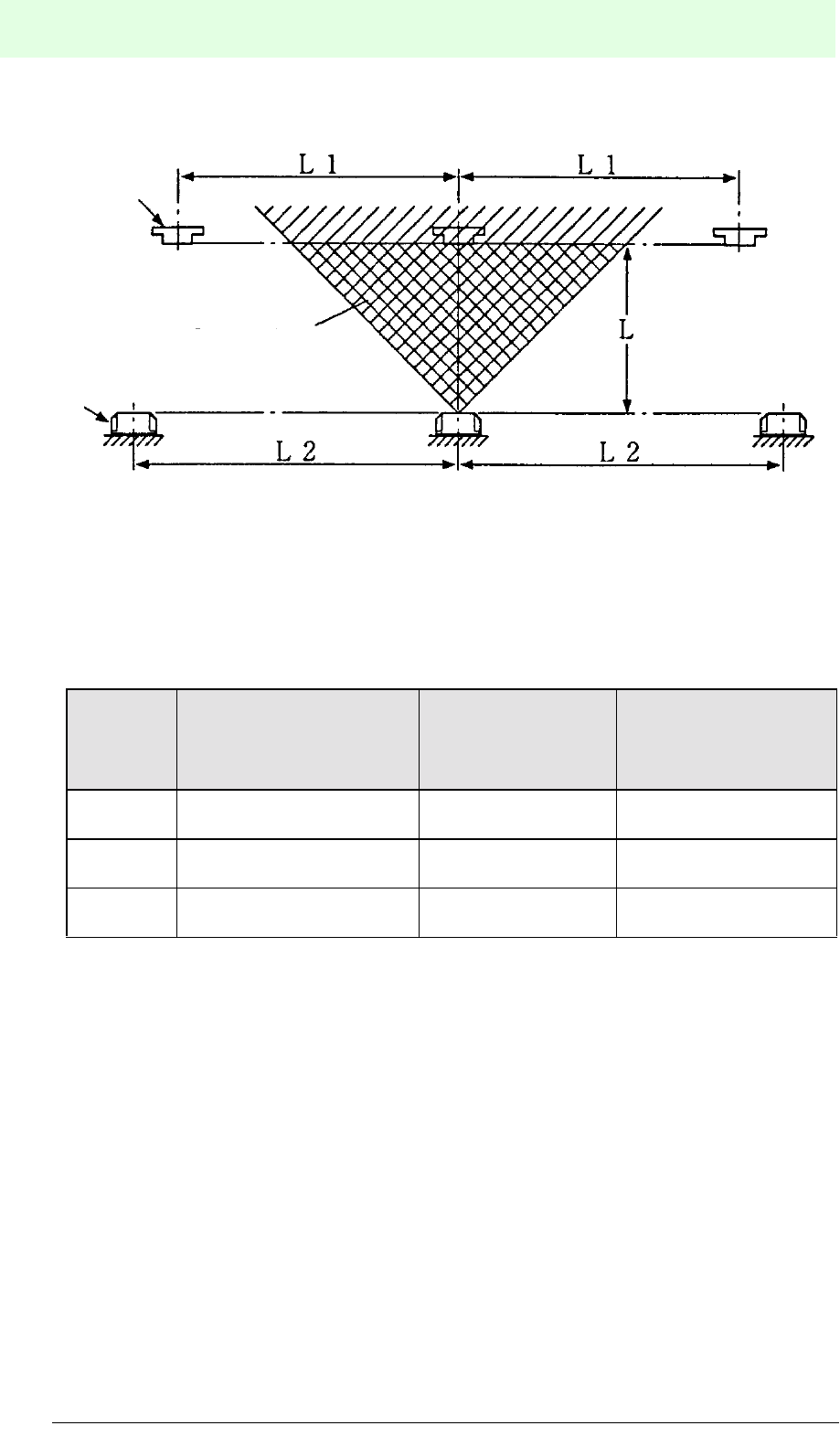
5.4.5 Mounting Distance
Mount the data carrier and the read/write head observing the distances L1 and
L2 listed in the table below.
When the “Detection time unlimited system” (Auto Read) operating mode is selected
as preset transmission mode, L1 must be double the distance shown above. The
following measures should be observed, when distances L1 and L2 cannot be
maintained in your production line:
• Use a read/write head with a smaller transmission range.
• Reduce distance L and choose an arrangement in which the data carriers are
moved through non-interfering transmission areas of the neighbouring read/write
heads.
• Activate the data carriers via their ID codes.
• When several read/write heads are located within the L2 range, program them in
such a way that the read/write heads do not communicate simultaneously.
1 Read/write head
2 Data carrier
3 Data transmission range
Read/write
head
Recommended distance
between read/write head
and data carrier
(L)
Specified distance
between
neighbouring data
carriers (L1)
Specified distance
between neighbouring
read/write heads (L2)
MVH500-
F15
0 mm ... 500 mm
(L)
longer than 2 x L
>1 m
longer than 4 x L
>2 m
MVH2000-
F15 200 mm ... 2,000 mm >4 m >8 m
MVH5000-
F50 500 mm ... 5,000 mm >8 m >16 m
1
2
3
IDENT-M System V
Installation
Date of issue 03.05.2001
35
Subject to reasonable modifications due to technical advances. Copyright Pepperl+Fuchs, Printed in Germany
Pepperl+Fuchs Group • Tel.: Germany (06 21) 7 76-0 • USA (330) 4 25 35 55 • Singapore 7 79 90 91 • Internet http://www.pepperl-fuchs.com
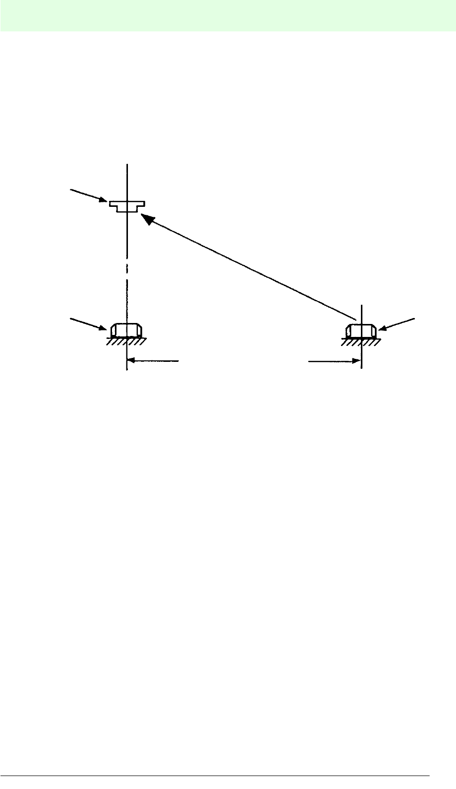
Note
When there is an object near the system, the data carrier may cause a transfer error
despite the above-mentioned distances being observed. For this reason, simulate the
arrangement of the system under present conditions in the field.
When the distance between neighbouring read/write heads is too short, the data
carrier may receive radio waves from the neighbouring read/write head.
1. Prevent both read/write heads from being operated at the same time.
2. Turn the read/write head mounting angle in such a way that the radio waves
cannot reach the neighbouring data carrier.
3. If the neighbouring read/write head is disturbed by interferences, the influenced
system retries the transmission process, provided that it is a transfer error due to
interferences. (When the neighbouring transfer is finished, the disturbed side
does not receive interferences upon retry).
4. Install a metal plate in order to prevent the radio waves from radiating to the
neighbouring system.
1 Data carrier
2 Read/write head
3 Distance between neighbouring read/write heads
1
22
3

IDENT-M System V
Installation
Date of issue 03.05.2001
36
Subject to reasonable modifications due to technical advances. Copyright Pepperl+Fuchs, Printed in Germany
Pepperl+Fuchs Group • Tel.: Germany (06 21) 7 76-0 • USA (330) 4 25 35 55 • Singapore 7 79 90 91 • Internet http://www.pepperl-fuchs.com
When the distance between neighbouring read/write heads is short, the data carrier
may receive radio waves from the neighbouring read/write head.
1. Perform the transmission in the “ID-code assignment” mode
2. Install a metal plate in order to screen the neighbouring data carriers from radio
waves.
5.4.6 Rate of Motion of the Data Carrier
While moving, the data carrier can transmit data by means of the read/write head.
However, its rate of motion is limited during the transmission process. The following
maximum speed should be observed:
Maximum permissible speed:
1 Data carrier
2 Read/write head
3 Distance between neighbouring data carriers
S [m/s]: Maximum permissible speed of the data carrier during the
transmission process.
W [mm]: Width of the transmission range, within which the data carrier
moves during the data transmission to the read/write head.
TC [ms]: Transfer time between read/write head and data carrier (see table
on page 37).
11
2
3
W
TC
S =

IDENT-M System V
Installation
Date of issue 03.05.2001
37
Subject to reasonable modifications due to technical advances. Copyright Pepperl+Fuchs, Printed in Germany
Pepperl+Fuchs Group • Tel.: Germany (06 21) 7 76-0 • USA (330) 4 25 35 55 • Singapore 7 79 90 91 • Internet http://www.pepperl-fuchs.com
Transfer Time between Read/Write Head and Data Carrier: TC
“TC” can be calculated from the function contents and the number of transmission
Bytes. The following transmission conditions apply:
Preset transmission mode: Detection time limited system without ID-
code assignment
Data carrier LED: Does not light
Execution of the data carrier's top address: 0000h
Transmission retry: No
Transmission function Transm.
code (octal)
Calculation of transmission time TC (ms)
(B as number of transmission Bytes)
Read 10hTC = 11.3 + 0.143 · B + M1 · 0.5 + M2 · 5.59
Read and check 11hTC = 16.4 + 0.286 · B + M1 + M2 · 11.2
Read ID code 12hTC = 7.5
Write 20h
B £ 256 Bytes
TC = 23.4 + 0.143 · B + M1 · 0.5 + M2 · 7.6
B ³ 257 Bytes
TC = 24.6 + 0.143 · B + M1 · 0.5 + M2 · 7.89
Write and check 21h
B £ 256 Bytes
TC = 28.3 + 0.286 · B + M1 + M2 · 12.9
B ³ 257 Bytes
TC = 29.8 + 0.286 · B + M1 + M2 · 13.5
Write ID code 22hTC = 12.2
Clear 30hTC = 13.7 + 0.006 · B
Initialise data carrier 31hTC = 26.7
Self-diagnosis of data
carrier 50hTC = 81.7 + 0.008 · B
ROM check 51hTC = 61.2
RAM check 52hTC = 13.2 + 0008 · B
Data carrier battery
life check 53hTC = 24.6
Block check 60hTC = 13.2 + 0.0032 · B
Variables of formulas: B: Number of transfer Bytes
M1: Round down the decimal of B/128 (e.g.: 32/128 = 0)
M2: Round down the decimal of B/256 (e.g.: 513/256 = 2)

IDENT-M System V
Installation
Date of issue 03.05.2001
38
Subject to reasonable modifications due to technical advances. Copyright Pepperl+Fuchs, Printed in Germany
Pepperl+Fuchs Group • Tel.: Germany (06 21) 7 76-0 • USA (330) 4 25 35 55 • Singapore 7 79 90 91 • Internet http://www.pepperl-fuchs.com
Example: The following illustration shows the read/write head reading 512 Byte data
when the pallet passes point A
Before position B is passed (data carrier leaves transmission range of read/write
head), the pallet should have already finished the read process. The maximum rate
of motion of the data carrier in this arrangement is S (in m/s). Reading of 512 byte
data (transfer code: 10h) results in the following maximum speed:
TC = 11.3 + 0.143 · 512 + M1 · 0.5 + M2 · 5.59
M1 = 512 ¸ 128
M2 = 512 ¸ 256
TC = 97.7 ms
S = 500 ¸ 97.7 = 5.1 m/s
The maximum rate of motion of the pallet is 5.1 m/s.
1 Read/write head
2 Data transmission
range
3 MVC data carrier
4 Direction of travel
5 Pallet
1
2
AB
3
45
IDENT-M System V
Installation
Date of issue 03.05.2001
39
Subject to reasonable modifications due to technical advances. Copyright Pepperl+Fuchs, Printed in Germany
Pepperl+Fuchs Group • Tel.: Germany (06 21) 7 76-0 • USA (330) 4 25 35 55 • Singapore 7 79 90 91 • Internet http://www.pepperl-fuchs.com
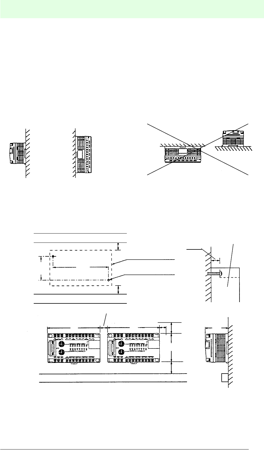
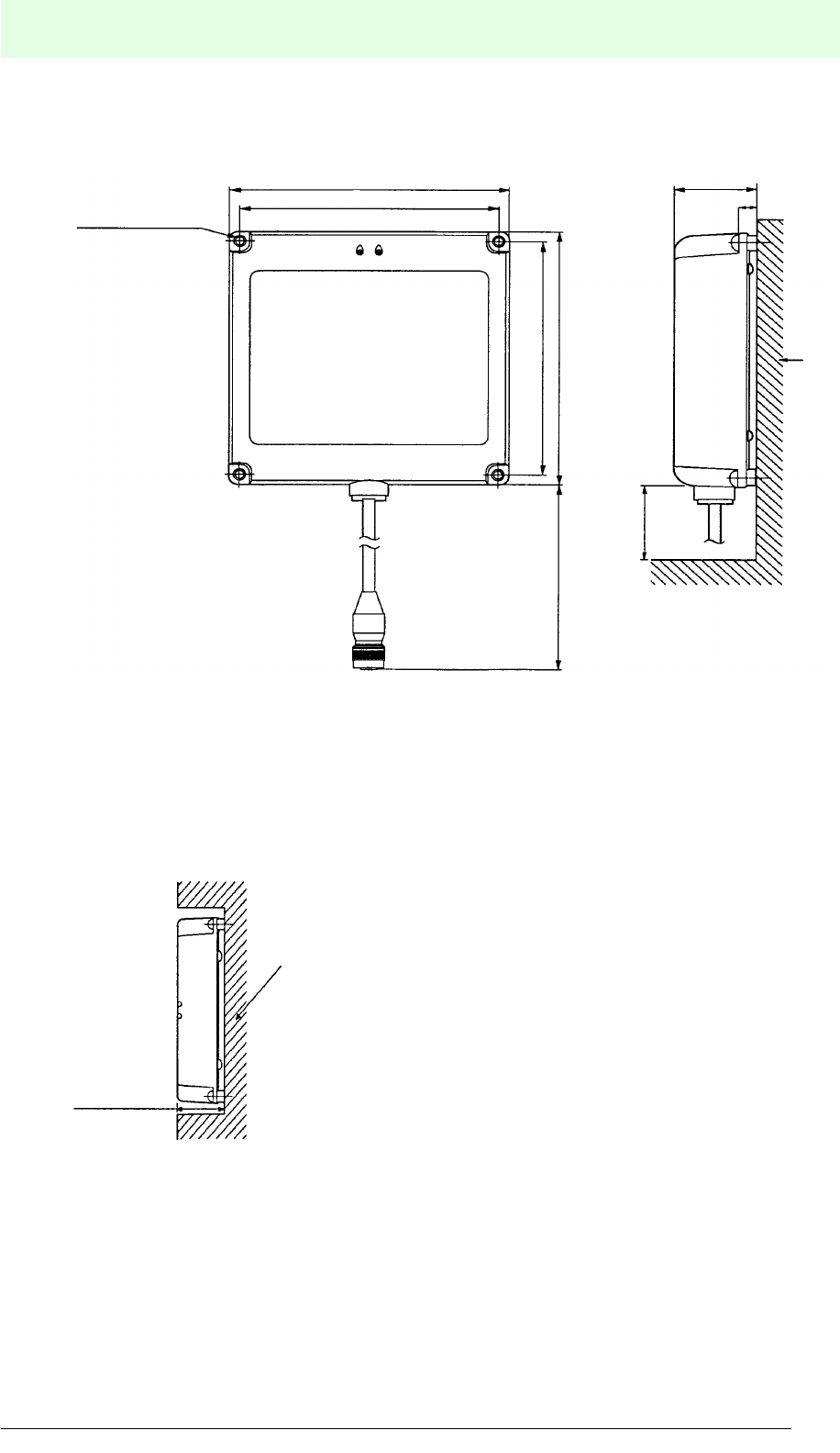
5.5 Mounting of Components
5.5.1 MVI-D2-2HRX Control Interface Unit
Be sure to mount the control interface unit as far away as possible from excessive
noise, high voltage lines, high voltage devices, electric cables and units which
generate radio waves.
Install the interface unit on a vertical surface.
Direct Installation
When installing the control interface unit directly on a panel, M4 screws of at least
20 mm length should be used. Observe a space of at least 10 mm to the left and right
and at least 20 mm on the top and bottom side of the MVI-D2-2HRX.
1Cable ducts
2 Cutout 140 mm x 80 mm
3 2 x M4 threads or 4.5 mm Øholes
Vertical installation Horizontal installation
1
1
³ 20 mm
³ 20 mm
³ 20 mm
³ 20 mm
1
³ 10 mm
80 mm
124 mm
140 mm
140 mm
67.8 mm
2
3
61.2 mm
MVI-D2-2HRX
15 mm
IDENT-M System V
Installation
Date of issue 03.05.2001
40
Subject to reasonable modifications due to technical advances. Copyright Pepperl+Fuchs, Printed in Germany
Pepperl+Fuchs Group • Tel.: Germany (06 21) 7 76-0 • USA (330) 4 25 35 55 • Singapore 7 79 90 91 • Internet http://www.pepperl-fuchs.com
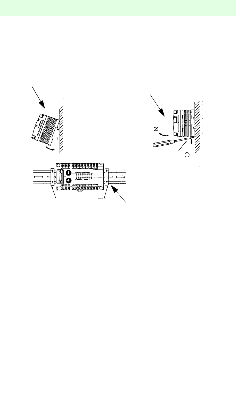
DIN Rail Mounting
Use of a DIN rail with 35 mm rail width fixed by the end plates.
Mounting
Position the backside groove of the control inter-
face unit on the DIN rail and press it down in arrow
direction.
Disassembly
Bend open the modules by means of a
screw driver and remove the control
interface unit from the DIN rail.
Fixing
Make sure the control interface unit is fastened by
means of end brackets (1).
11
IDENT-M System V
Installation
Date of issue 03.05.2001
41
Subject to reasonable modifications due to technical advances. Copyright Pepperl+Fuchs, Printed in Germany
Pepperl+Fuchs Group • Tel.: Germany (06 21) 7 76-0 • USA (330) 4 25 35 55 • Singapore 7 79 90 91 • Internet http://www.pepperl-fuchs.com
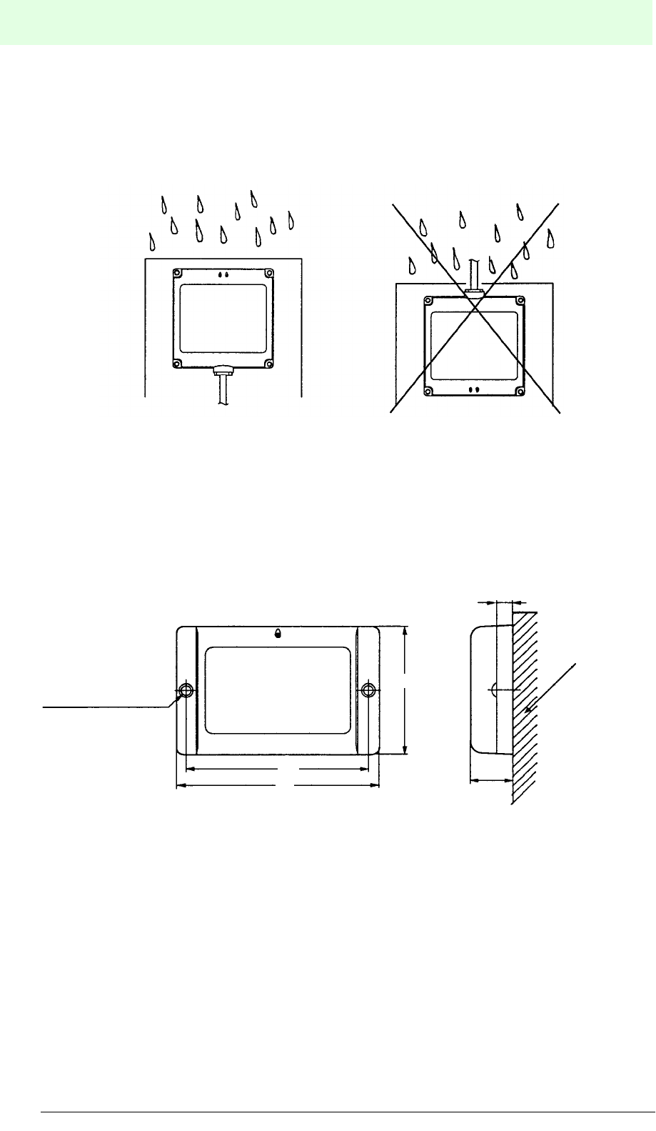
5.5.2 Read/Write Heads
Mounting in Metal Housing
Mounting the read/write head in a metal
object. The dimensions for the mounting
depth of the read/write head, listed below,
should be observed. Mounting the read/
write head deeper than indicated, causes
the specified transfer range to diminish.
1 4 x Ø4.5 mm hole, depth 8 mm
2³ 75 mm for bending the cable
3 Transportation plant or the like
40 mm
140 mm
130 mm
140 mm
130 mm
L = 3 m
1
2
3
£ 40 mm
Metal housing
IDENT-M System V
Installation
Date of issue 03.05.2001
42
Subject to reasonable modifications due to technical advances. Copyright Pepperl+Fuchs, Printed in Germany
Pepperl+Fuchs Group • Tel.: Germany (06 21) 7 76-0 • USA (330) 4 25 35 55 • Singapore 7 79 90 91 • Internet http://www.pepperl-fuchs.com
Mounting in Humid Rooms
The read/write head has to be mounted in such a way that no liquid can penetrate the
housing through the cable exit, when there is precipitation in humid rooms.
5.5.3 Data Carrier
Mounting the Data Carrier by Means of Screws
Fix the data carrier by means of M4 screws through mounting screw holes, for
instance onto a pallet.
2 x bore hole Æ4.5
Hole depth: 8
80
90
60
Pallet
etc.
8
IDENT-M System V
Installation
Date of issue 03.05.2001
43
Subject to reasonable modifications due to technical advances. Copyright Pepperl+Fuchs, Printed in Germany
Pepperl+Fuchs Group • Tel.: Germany (06 21) 7 76-0 • USA (330) 4 25 35 55 • Singapore 7 79 90 91 • Internet http://www.pepperl-fuchs.com
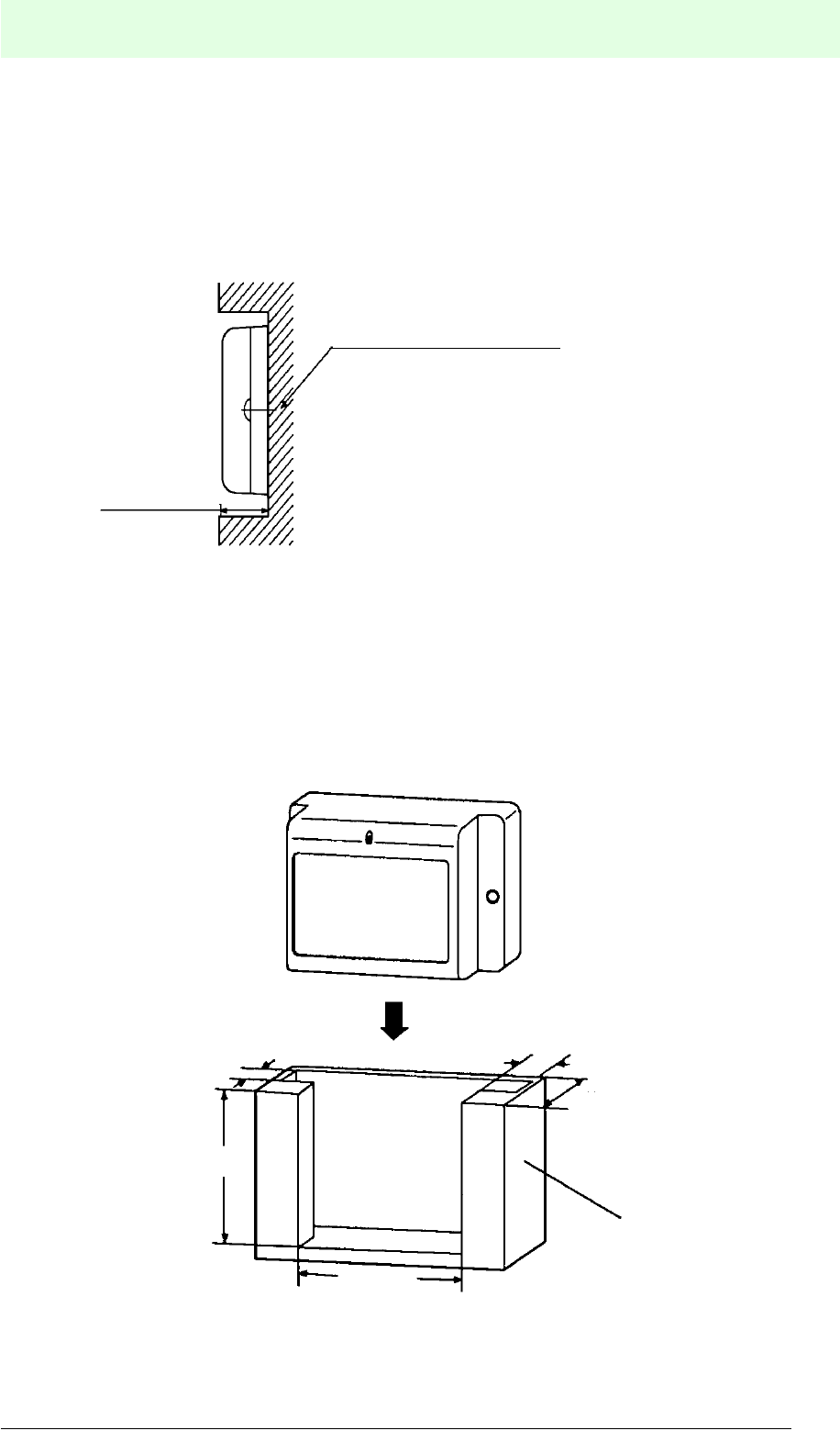
Mounting the Data Carrier in a Metal Housing
The dimensions for the mounting depth of the data carrier, listed below, should be
observed. Mounting the read/write head deeper than indicated, causes the specified
transfer range to diminish.
Using an Installation Holder
In order to facilitate the replacement of the data carrier in the system, we recommend
manufacturing an installation holder (1). The use of such a holder simplifies the
replacement of the data carrier for maintenance and repair.
£ 20 mm
Metal
20 mm
³ 71 mm
³ 10 mm
³ 8.5 mm
60 mm
1
IDENT-M System V
Installation
Date of issue 03.05.2001
44
Subject to reasonable modifications due to technical advances. Copyright Pepperl+Fuchs, Printed in Germany
Pepperl+Fuchs Group • Tel.: Germany (06 21) 7 76-0 • USA (330) 4 25 35 55 • Singapore 7 79 90 91 • Internet http://www.pepperl-fuchs.com
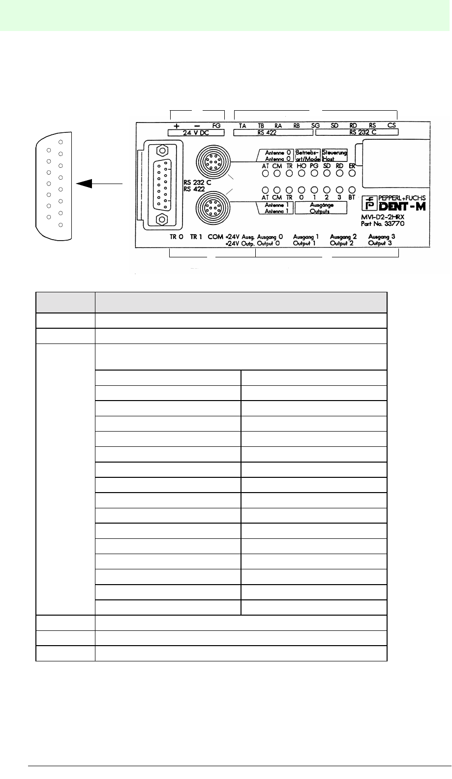
5.6 Connections of the MVI-D2-2HRX Control Interface Unit
5.6.1 Overview
Fig. Assignment
1 Terminals for RS 232/RS 422 interface
2 Terminals for DC 24 V power supply
3
Connectors for RS 232 /RS 422 interface to the
host controller
PIN No. Signal
1FG
2SD
3TA (+)
4RD
5RTS
6SG
7SG
8CS
9RA (+)
10 RB (-)
11 TB (-)
12 RS
13 RTS
14 +5 V
15 +5 V
4 Terminals for the trigger input
5 Terminals for the outputs
6 Connections for two read/write heads
3
1
8
9
15
4
21
5
6
IDENT-M System V
Installation
Date of issue 03.05.2001
45
Subject to reasonable modifications due to technical advances. Copyright Pepperl+Fuchs, Printed in Germany
Pepperl+Fuchs Group • Tel.: Germany (06 21) 7 76-0 • USA (330) 4 25 35 55 • Singapore 7 79 90 91 • Internet http://www.pepperl-fuchs.com
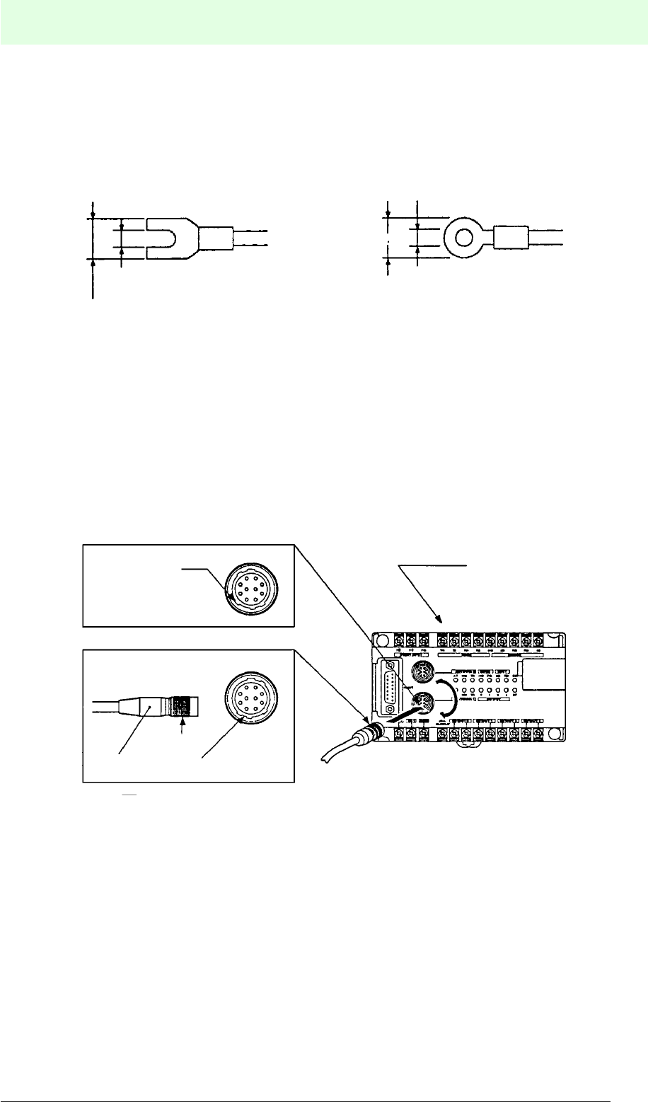
Terminals
All terminals of the MVI-D2-2HRX are mounted with M3 screws. Use crimp terminals
and tighten them with a torque of 4 to 8 kg/cm.
Recommended crimp terminals:
5.6.2 Connection of the MVI-D2-2HRX Control Interface Unit
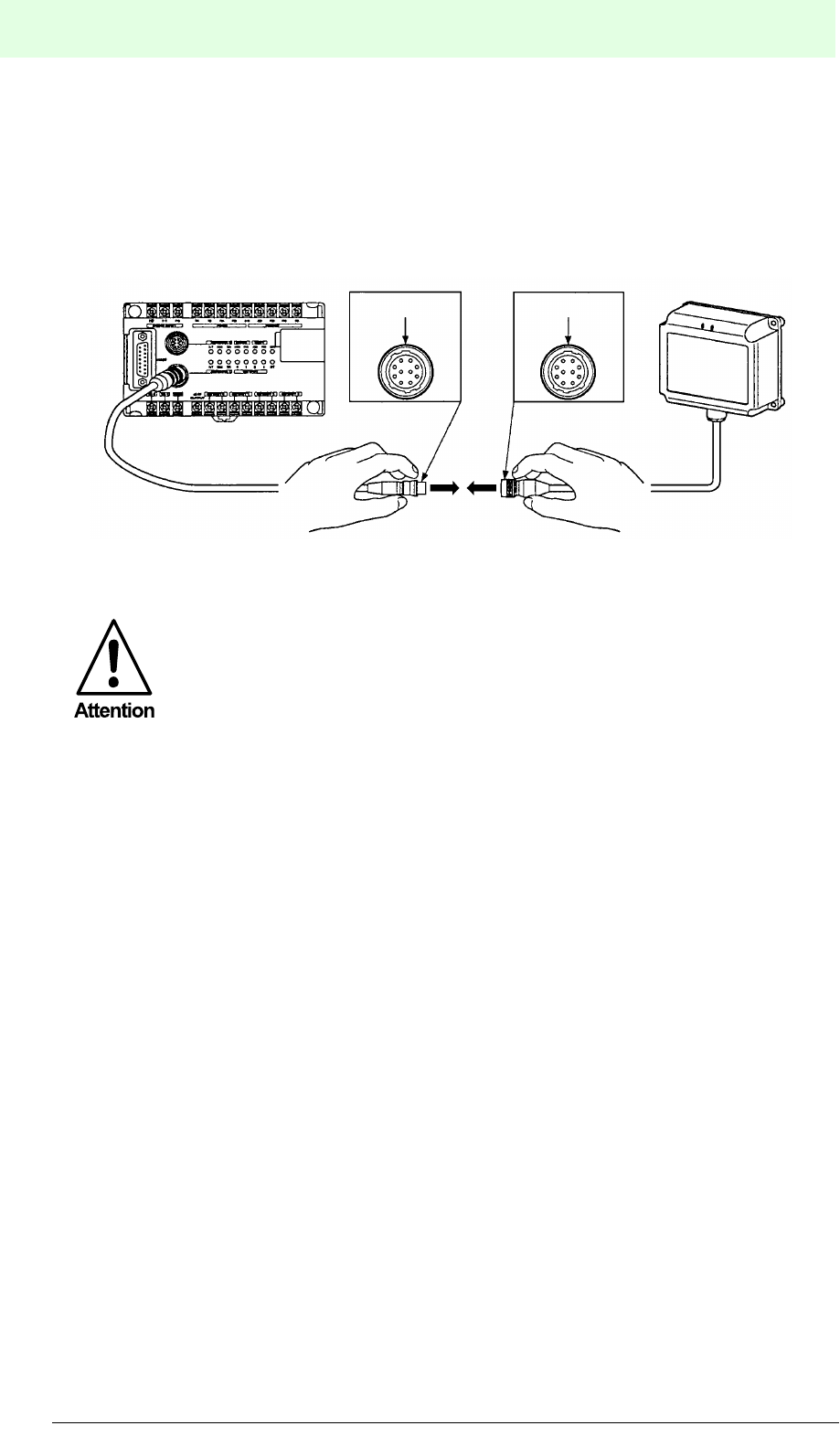
Take the connector of the read/write head (1) for connecting it to the control interface
unit and match the protrusions of the connector (2) with the dents of the MVI-D2-
2HRX connector plug. Then press in and push the sliding bushing (3) forwards. When
a “click” sound is heard, the connection is completed. In order to release the
connection, pull the sliding bushing (3) backwards and unplug the connector (1).
3.2 mm (min.) 3.2 mm (min.)
6.3 mm (max.)
5.5 mm
MVI-D2-2HRX
12
2
3
IDENT-M System V
Installation
Date of issue 03.05.2001
46
Subject to reasonable modifications due to technical advances. Copyright Pepperl+Fuchs, Printed in Germany
Pepperl+Fuchs Group • Tel.: Germany (06 21) 7 76-0 • USA (330) 4 25 35 55 • Singapore 7 79 90 91 • Internet http://www.pepperl-fuchs.com
Connection of extension cable MVK-5/ MVK-10/ MVK-20/ MVK-30
The length of the read/write head connection cables, is indicated in the data sheets.
When a longer cable is required, use any of the extension cables (MVK-5/ MVK-10/
MVK-20/ MVK-30) with the appropriate length. The number given in the type code
corresponds to the length in meters.
The read/write heads connector of the extension cable is not
waterproof. Therefore, this connection of the read/write head should not
come into contact with water. If the connection must be waterproof, we
advise to use self-adhesive insulating tape.
When the extension cable has a loose connection, this may lead to a
malfunction of the control interface unit. Make sure, the connection is
fixed, so that it may not work loose.
IDENT-M System V
Installation
Date of issue 03.05.2001
47
Subject to reasonable modifications due to technical advances. Copyright Pepperl+Fuchs, Printed in Germany
Pepperl+Fuchs Group • Tel.: Germany (06 21) 7 76-0 • USA (330) 4 25 35 55 • Singapore 7 79 90 91 • Internet http://www.pepperl-fuchs.com
5.6.3 Connecting the MVI-D2-2HRX Control Interface Unit to a Host Controller
For connecting the host controller to the MVI-D2-2HRX, both RS 232C and RS 422
are available as standard interface types. Choose one of the interface systems by
setting switch 1 to 6. For connecting the interface, refer to the connection diagrams
given below.
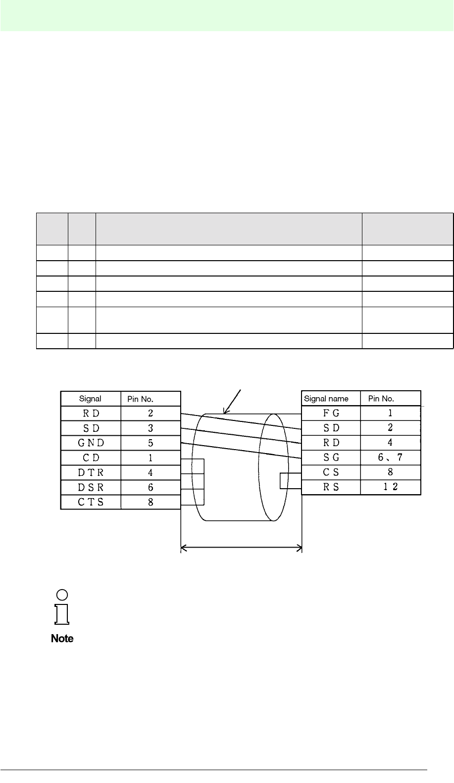
RS 232
The following table shows the signal names of the terminals for the RS 232C
connection as well as the pin numbers of the connector for the MVI-D2-2HRX host
controller.
.
Sig-
nal
Pin
No. Function
FG 1 Connect with frame ground Frame ground
SD 2 Sends data (from MVI-D2-2HRX to host controller) Send Data
RD 4 Receives data (from host controller to MVI-D2-2HRX) Receive Data
SG 6,7 Signal ground Signal Ground
CS 8 ON: MVI-D2-2HRX can send data
OFF: Sending data locked Clear to Send
RS 12 Switches ON while MVI-D2-2HRX operates Request to Send
The length of the RS 232 interface cable must not exceed 15 m.
IBM PC MVI-D2-2HRX
£ 15 m
Screen
IDENT-M System V
Installation
Date of issue 03.05.2001
48
Subject to reasonable modifications due to technical advances. Copyright Pepperl+Fuchs, Printed in Germany
Pepperl+Fuchs Group • Tel.: Germany (06 21) 7 76-0 • USA (330) 4 25 35 55 • Singapore 7 79 90 91 • Internet http://www.pepperl-fuchs.com
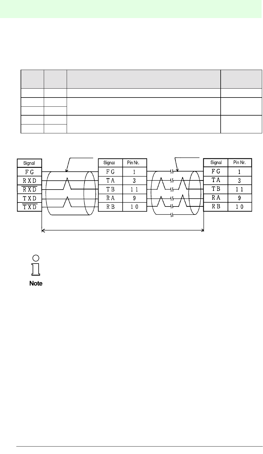
RS 422
The following table shows the signal names of the terminals for the RS 422
connection as well as the pin numbers of the connector for the MVI-D2-2HRX.
Sig-
nal
Pin
No. Function
FG 1 Connect with frame ground Frame ground
TA (+) 3 Sends data (from MVI-D2-2HRX to host controller) Transmit data
TB (-) 11
RA (+) 9 Receives data (from host controller to MVI-D2-2HRX) Receive Data
RB (-) 10
The length of the RS 422 interface cable must not exceed 1,200 m.
We recommend cable type:
UNITRONICÒ -Li1YCY (TP)
£ 1200 m
Computer MVI-D2-2HRX
Screen MVI-D2-2HRX Screen
IDENT-M System V
Installation
Date of issue 03.05.2001
49
Subject to reasonable modifications due to technical advances. Copyright Pepperl+Fuchs, Printed in Germany
Pepperl+Fuchs Group • Tel.: Germany (06 21) 7 76-0 • USA (330) 4 25 35 55 • Singapore 7 79 90 91 • Internet http://www.pepperl-fuchs.com
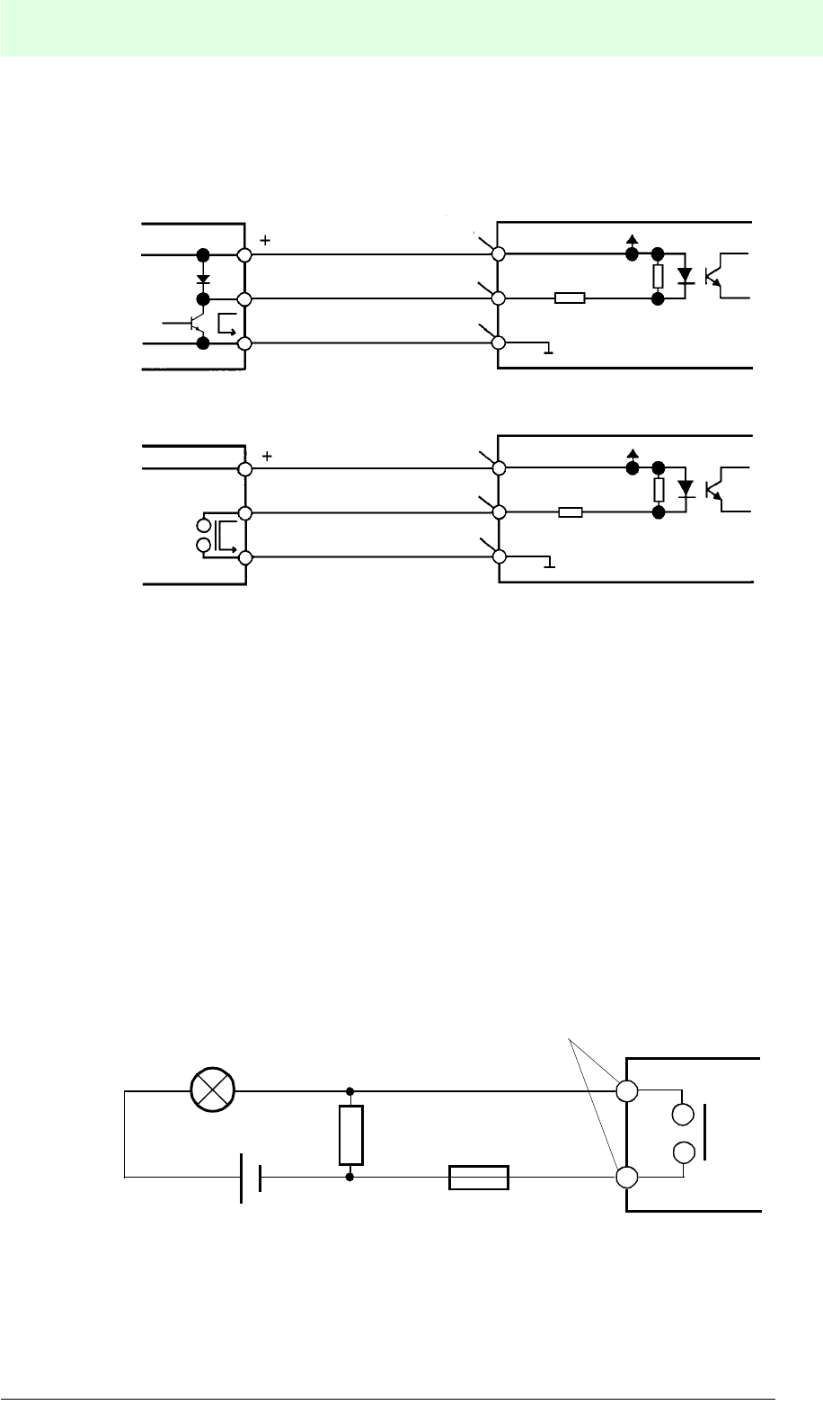
5.6.4 Connection to the Trigger Inputs
Connect a DC input to the trigger input as shown in the following figure:
5.6.5 Connection of the Outputs
Connect output terminals “OUTPUT 0, 1, 2, and 3” according to the following
instructions.
Protection against Shorted Output
When the output is shorted, the output circuit of the control interface unit may be
destroyed. That is why a fuse should be integrated in order to protect the output.
Precautions against Surge Currents at Lamp Load
An incandescent lamp can generate a surge 10 to 20 times greater than the nominal
current. Two precautions can be taken in order to decrease the surge: Inserting a
bleeder resistor or inserting a current limiting resistor.
Inserting Bleeder Resistor
Supplies only low current so that the lamp does not light while the output is switched
off.
MVI-D2-2HRX
MVI-D2-2HRX
NPN
output
Relay
output
0 V
0 V
+24 V out
TR0 or TR1
COM
+24 V out
TR0 or TR1
COM
+24 V
+24 V
Output component MVI-D2-2HRX
Output 0/1/2/3
Bleeder resistor
Fuse
IDENT-M System V
Installation
Date of issue 03.05.2001
50
Subject to reasonable modifications due to technical advances. Copyright Pepperl+Fuchs, Printed in Germany
Pepperl+Fuchs Group • Tel.: Germany (06 21) 7 76-0 • USA (330) 4 25 35 55 • Singapore 7 79 90 91 • Internet http://www.pepperl-fuchs.com
Inserting Current Limiting Resistor
The resistor limits the current to the nominal current. The current supplying the lamp
decreases, when the resistance is high. Adjust the resistance value, so that the lamp
lights bright enough.
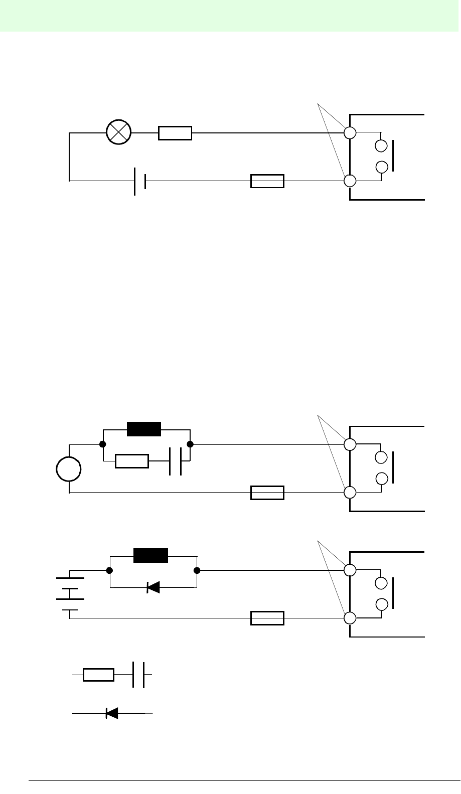
Protective Measures against Surges in Inductive Loads
When the circuit is opened by a coil, some thousand volts of voltage surge may occur,
depending on the coil. When a coil generates a high voltage, appropriate protective
measures should be taken against the surge. Protective measures against voltage
surge may extend the lifetime of the relay.
• Protective measures against voltage surge
In the case of alternating voltage, varistors show the same effect as RC modules.
Output component MVI-D2-2HRX
Output 0/1/2/3
Current limiting
resistor
Fuse
Output component
MVI-D2-2HRX
Output 0/1/2/3
~
Coil
Overvoltage protection
Fuse
Output component
MVI-D2-2HRX
Output 0/1/2/3
+
Coil
Diode
Fuse
RC module:
C: 0.033 mF ... 0.33 mF (with UC ³ 250 VAC)
R: 47 W ... 120 W
Diode: The peak off-state voltage should be higher
than 300 % of the nominal voltage. The rectified
current should be higher than the nominal current.
IDENT-M System V
Installation
Date of issue 03.05.2001
51
Subject to reasonable modifications due to technical advances. Copyright Pepperl+Fuchs, Printed in Germany
Pepperl+Fuchs Group • Tel.: Germany (06 21) 7 76-0 • USA (330) 4 25 35 55 • Singapore 7 79 90 91 • Internet http://www.pepperl-fuchs.com
Connection of low-voltage devices (24 VDC, 10 mA)
In the case of low tension and weak current, a reliable contact is established to the
opposite equipment by means of a miniature relay. In the case of alternating voltage,
the effect is the same when using a varistor instead of an RC overload protection.
Mounting both, RC overload protection and varistor has a better effect.
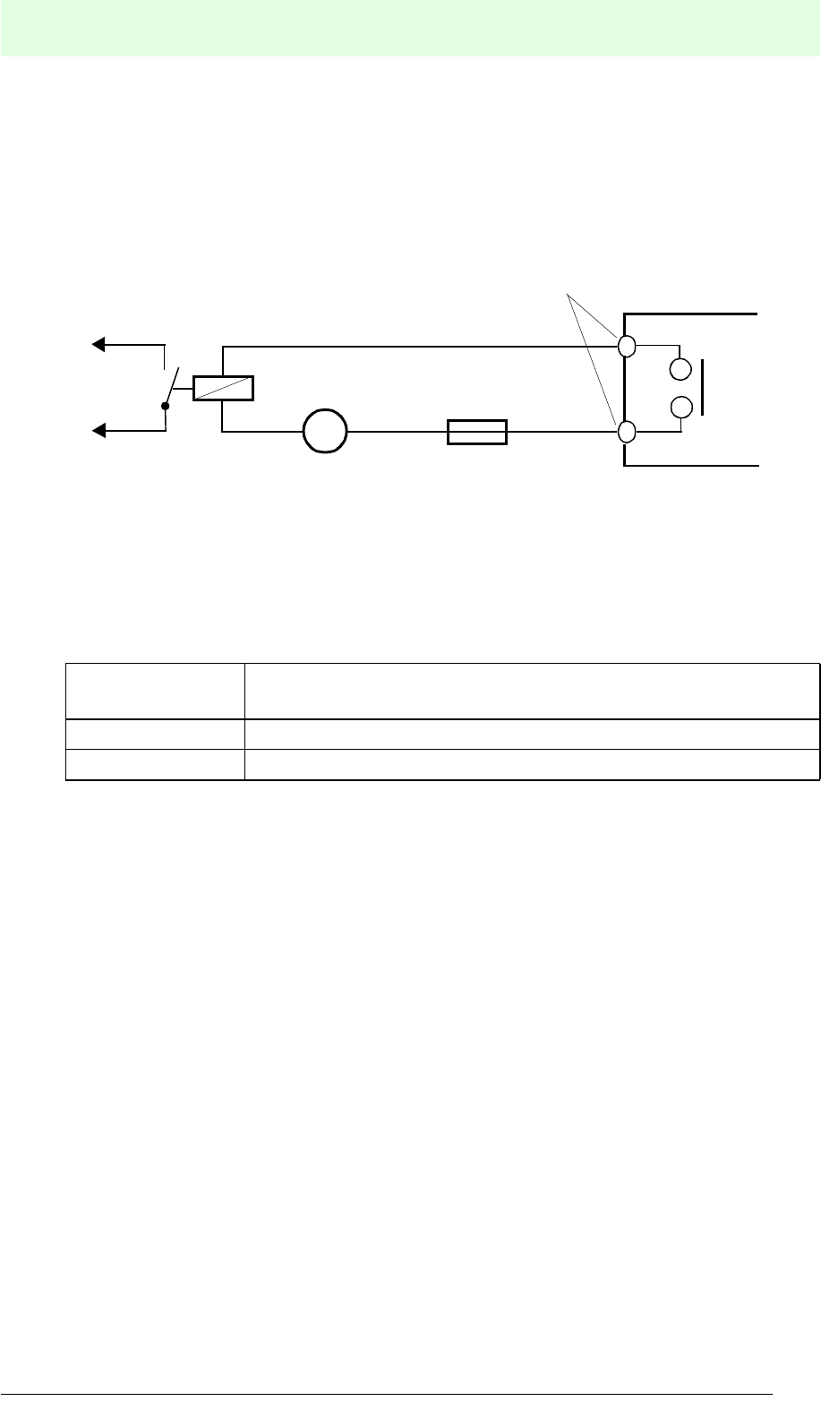
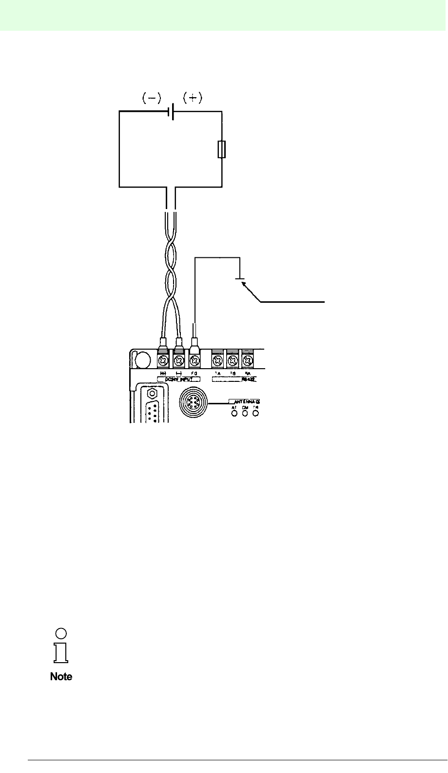
5.6.6 Connection of the Power Supply
Connect the current source with 24 VDC to the MVI-D2-2HRX power supply
connection.
Power supply:
Power supply 24 VDC ±10 % (including ripple voltage, value at the MVI-D2-
2HRX connection)
Amperage More than 1 A
Ripple voltage Less than 200 mV (at maximum load)
Output component MVI-D2-2HRX
Output 0/1/2/3
~
Opposite
equip-
ment
Fuse
IDENT-M System V
Installation
Date of issue 03.05.2001
52
Subject to reasonable modifications due to technical advances. Copyright Pepperl+Fuchs, Printed in Germany
Pepperl+Fuchs Group • Tel.: Germany (06 21) 7 76-0 • USA (330) 4 25 35 55 • Singapore 7 79 90 91 • Internet http://www.pepperl-fuchs.com
Note
Be careful not to mistake positive and negative poles at the MVI-D2-2HRX power
supply connection. Mistaking the poles may damage the MVI-D2-2HRX and the read/
write heads.
5.7 Dismantling, Packing and Disposal
Repacking
The device should be well packed for reuse, so that protection is provided against
shock and dampness. Optimum protection is afforded by the original packaging.
Disposal
Electronic waste is special refuse. Be sure to observe the local
regulations for its disposal.
24 VDC
GND
Fuse
1.2 A
IDENT-M System V
Commissioning
Date of issue 03.05.2001
53
Subject to reasonable modifications due to technical advances. Copyright Pepperl+Fuchs, Printed in Germany
Pepperl+Fuchs Group • Tel.: Germany (06 21) 7 76-0 • USA (330) 4 25 35 55 • Singapore 7 79 90 91 • Internet http://www.pepperl-fuchs.com
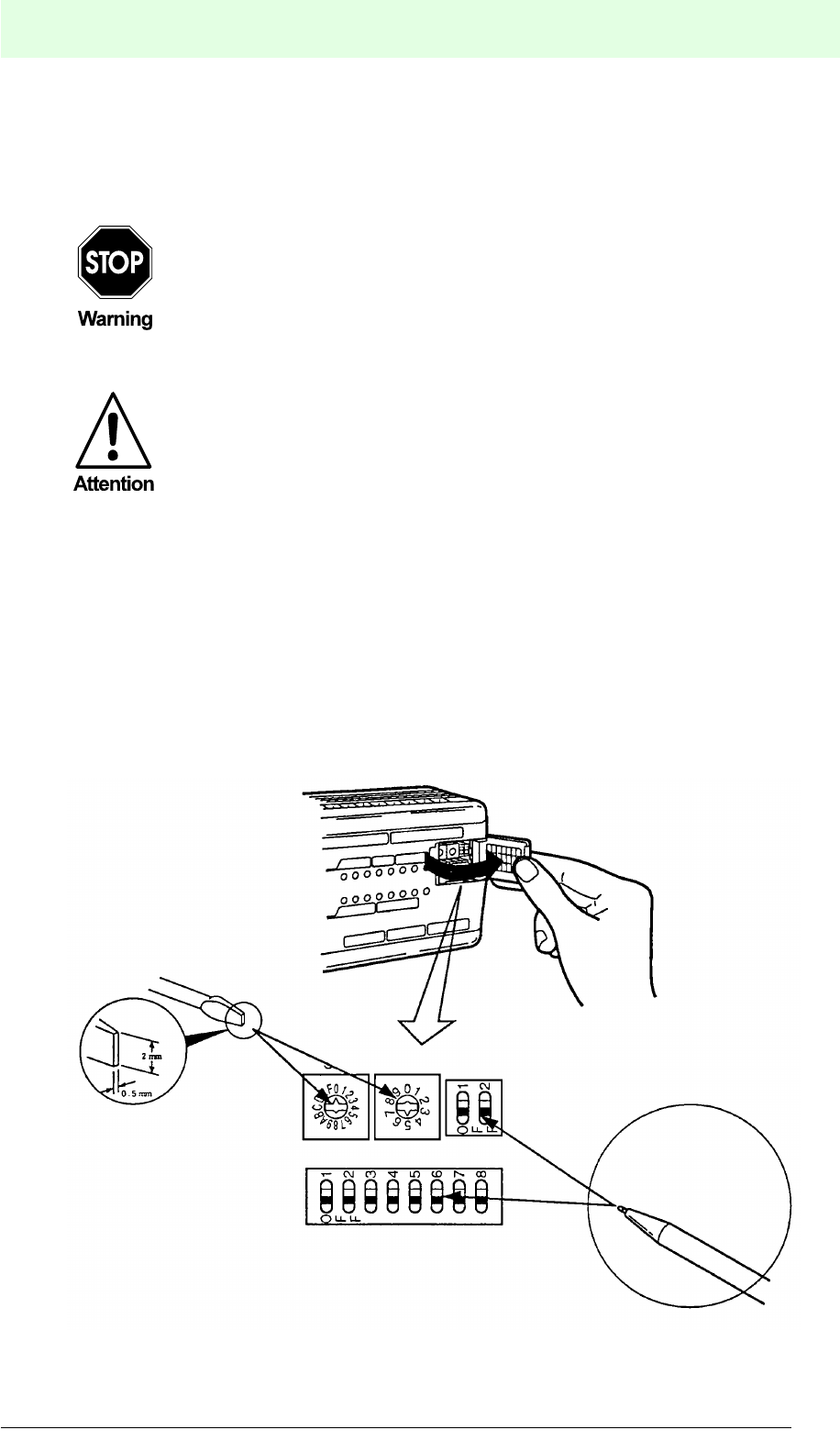
6 Commissioning
6.1 Check List
6.2 Adjusting the Switches on the MVI-D2-2HRX Control Interface Unit
The switches are located underneath a cover on the control interface unit.
The transmission conditions between a host controller and the control interface unit
are set by means of the switches.
Open the cover in the direction of the arrow. Set the SW2 and SW3 rotary switches
using a 0.5 x 2.0 slotted screwdriver (see 1). Set the SW1 and SW4 DIP-switches
using a pointed tool or a ball point pen (see 2).
Before commissioning, make sure that the plant in which the device is
integrated, cannot be damaged e.g. by uncontrolled trigger processes.
Before commissioning, check once again that the connections are
correct.
1
2
SW1
SW2
SW3 SW4

IDENT-M System V
Commissioning
Date of issue 03.05.2001
54
Subject to reasonable modifications due to technical advances. Copyright Pepperl+Fuchs, Printed in Germany
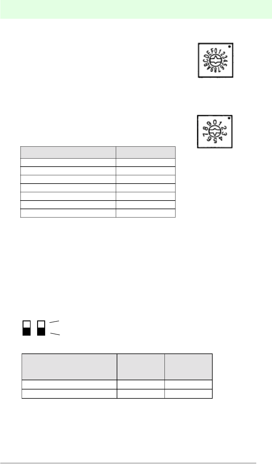
Pepperl+Fuchs Group • Tel.: Germany (06 21) 7 76-0 • USA (330) 4 25 35 55 • Singapore 7 79 90 91 • Internet http://www.pepperl-fuchs.com
SW1:
Adjustment of data length, parity, stop bit, type of connection, data transfer standard,
2 or 4-wire system and high speed mode. Positions identified with “·” in the tables
represent the basic settings at the delivery.
Data bits SW1-1
8 bit ON
· 7 bit OFF
Parity SW1-2 SW1-3
Even ON OFF
Odd ON ON
· None OFF *)
*) ON or OFF - basic setting is OFF.
Stop bits SW1-4
2 bit ON
· 1 bit OFF
Connection type SW1-5
· Host controller has a serial interface OFF*
*) Make sure, SW1-5 is always set to OFF.
Wiring standard*) SW1-6 SW1-7
RS 422
(4-wire connection) ON OFF
RS 422
(2-wire connection) OFF ON
· RS 232C OFF OFF
*) Connection see chapter 4.1 “System Structure”
Mode of operation SW1-8
· High speed mode OFF
*) Make sure, SW1-8 is always set to OFF.
1 2 3 4 65 7 8 ON
OFF
IDENT-M System V
Commissioning
Date of issue 03.05.2001
55
Subject to reasonable modifications due to technical advances. Copyright Pepperl+Fuchs, Printed in Germany
Pepperl+Fuchs Group • Tel.: Germany (06 21) 7 76-0 • USA (330) 4 25 35 55 • Singapore 7 79 90 91 • Internet http://www.pepperl-fuchs.com
SW4:
Set terminal resistance.
SW4-1
(for 2-wire
connection)
SW4-2
(for 4-wire
connection)
Terminal station ON ON
Interstation OFF OFF
SW2:
Set station number “0” to “F” (RS 422).
(Normal position: “0”)
SW3:
Set transmission speed.
(Normal position: 5)
Transmission speed (baud) Switch position
300 0
600 1
1200 2
2400 3
4800 4
9600 5
19200 6
Switch positions 7, 8 and 9 are reserved.
1 2 ON
OFF

IDENT-M System V
Communication Systems
Date of issue 03.05.2001
56
Subject to reasonable modifications due to technical advances. Copyright Pepperl+Fuchs, Printed in Germany
Pepperl+Fuchs Group • Tel.: Germany (06 21) 7 76-0 • USA (330) 4 25 35 55 • Singapore 7 79 90 91 • Internet http://www.pepperl-fuchs.com
7 Communication Systems
7.1 Overview
You can choose between four communication startup systems and two response
return systems for communication between the host controller and the MVI-D2-
2HRX control interface unit.
When the occasional execution system or the command stay system are chosen as
communication startup system, the MVI-D2-2HRX can simultaneously execute
multiple commands (see page 57 and page 87 “Simultaneous Processing of
Commands”).
7.1.1 Communication Startup System
Based on the conditions for the MVI-D2-2HRX trigger inputs, the communication
startup system is classified as follows:
• Commands that access the data carriers are available for each system.
• The occasional execution system is automatically used, when commands only
address the control interface unit without accessing a data carrier.
• The type of the communication startup system is set by writing one byte to the
A008h address of the control interface unit's system memory:
Communication startup system Response return system
Occasional execution system Auto response system
Response request system
Command stay system Auto response system
Response request system
Command register system Auto response system
Response request system
Read/write head scan system Auto response system
Response request system
Communication startup system
Occasional execution system Trigger input is not used
Command stay system
Communication with the data carriers is triggered by
the sensor which is connected to the trigger input.
Command register system
Read/write head scan system Trigger input is not used
Value Explanation Active trigger inputs
0 Occasional execution system (basic setting) no
1 Command stay system yes
2 Command register system yes
3 Read/write head scan system no

IDENT-M System V
Communication Systems
Date of issue 03.05.2001
57
Subject to reasonable modifications due to technical advances. Copyright Pepperl+Fuchs, Printed in Germany
Pepperl+Fuchs Group • Tel.: Germany (06 21) 7 76-0 • USA (330) 4 25 35 55 • Singapore 7 79 90 91 • Internet http://www.pepperl-fuchs.com
Application
Occasional execution system:
• The MVI-D2-2HRX immediately executes a command.
• Used, when the host controller detects the presence of a data carrier:
1. Started, by connecting the proximity switch to the host controller.
2. Data carrier identification time: endless. Starts, when a data carrier is detected.
3. An operator judges the existence of a data carrier and starts the command, for
instance, by striking a key.
Command stay system:
• When the MVI-D2-2HRX detects the existence of a data carrier by means of a
proximity switch which is connected to a trigger input, the MVI-D2-2HRX executes
the current command and returns the result to the host controller.
• After completion of the command stay system operation, the MVI-D2-2HRX is
ready for operation in the occasional execution system (available for
simultaneous multiple operations).
• Used, when existence of a data carrier can be detected e.g. by a proximity switch
and when the command has already been registered prior to the detection.
• Differences from the command register system:
1. Commands can be easily changed by the host controller's program.
2. Commands are purged after each operation.
3. The host controller has to send a new command after each operation.
4. Different modes of operation are available for each trigger input.
5. The command stay system performs in a sensible manner, when the result
influences the next command.
Command Register System:
• For each detection of a data carrier by means of the proximity switch which is
connected to the trigger input. The MVI-D2-2HRX executes the command stored
in the MVI-D2-2HRX and sends the result to the host controller.
• The command is stored to the MVI-D2-2HRX system memory.
• The command which is to be executed on activation of the trigger input, has been
stored to the system memory in advance.
• Other stored commands are available until the trigger input is switched off
(available for simultaneous multiple operations).
• Used, when existence of a data carrier can be detected, for instance by means of
a proximity switch and when all transmission processes with the data carrier have
already been registered.

IDENT-M System V
Communication Systems
Date of issue 03.05.2001
58
Subject to reasonable modifications due to technical advances. Copyright Pepperl+Fuchs, Printed in Germany
Pepperl+Fuchs Group • Tel.: Germany (06 21) 7 76-0 • USA (330) 4 25 35 55 • Singapore 7 79 90 91 • Internet http://www.pepperl-fuchs.com
• Simple installation, because on-site connection of the proximity switch to the MVI-
D2-2HRX is possible.
• Differences from the command stay system:
1. The command does not disappear when the MVI-D2-2HRX is battery-buffered.
This means that it is not necessary to send a command to the control interface
unit at the end of each operation.
2. Commands are changed by altering the register content of the MVI-D2-2HRX.
3. During an individual operation, the host contoller can concentrate on receiving a
response from the MVI-D2-2HRX, enabling the host controller to perform less
tasks.
Read/Write Head Scan System:
The read/write scan system supports commands which address individual read/write
heads, as well as scan commands for all connected control interface units and read/
write heads.
7.1.2 Response Return System
Two systems, the auto response system and the response request system are
available for response from the MVI-D2-2HRX to the host controller.
• The system type is set by writing one byte to the A00Ah address of the control
interface unit's system memory:
Auto response system
• After ending the transmission procedure, the MVI-D2-2HRX automatically returns
the transmission result (end message) to the host controller.
• The end message timing cannot be determined by the host controller.
Application:
• Mainly used for configuration of a host controller and a MVI-D2-2HRX connection.
• Used for transmission configuration of the host controller and multiple MVI-D2-
2HRX.
In order to prevent collision of responses on transmission lines, it is better not to
start the next command of another station, until the command of the currently
transmitting station is completed.
Value Command
0 Auto response system (basic setting)
1 Response request system

IDENT-M System V
Communication Systems
Date of issue 03.05.2001
59
Subject to reasonable modifications due to technical advances. Copyright Pepperl+Fuchs, Printed in Germany
Pepperl+Fuchs Group • Tel.: Germany (06 21) 7 76-0 • USA (330) 4 25 35 55 • Singapore 7 79 90 91 • Internet http://www.pepperl-fuchs.com
Response request system
• After completion of the command, the MVI-D2-2HRX returns the transmission
result (end message) to the host controller, in accordance with the request from
the host contoller (hereafter referred to as “acknowledgement request”).
• The host controller prescribes the timing for sending the end message.
Application:
• Mainly used for the configuration of a host controller and multiple MVI-D2-2HRX.
• Since the system returns the end message on request of the host controller, its
processing time is longer than the auto response system's processing time.
7.2 Occasional Execution System
Unlike the command stay system and the command register system, the occasional
execution system can start accessing the data carrier via the host controller,
regardless of the MVI-D2-2HRX trigger input condition.
7.2.1 Occasional Execution System + Auto Response System
Transmission Procedure
1. The host controller sends commands to the MVI-D2-2HRX.
2. After receiving the commands, the MVI-D2-2HRX returns an acknowledgement
to the host controller.
3. After the command has been executed, the MVI-D2-2HRX returns the end
message to the host controller.
Transmission Sequence
Numbers (1) to (3) correspond to the above-mentioned transmission procedures.
Check station number
Execute communication command
Send command (1)
Send acknowledgement (2)
Send end message (3)
Control interface unitHost controller
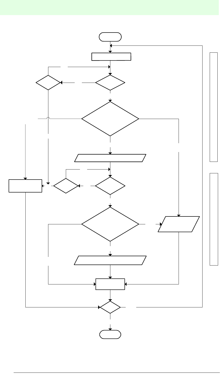
IDENT-M System V
Communication Systems
Date of issue 03.05.2001
60
Subject to reasonable modifications due to technical advances. Copyright Pepperl+Fuchs, Printed in Germany
Pepperl+Fuchs Group • Tel.: Germany (06 21) 7 76-0 • USA (330) 4 25 35 55 • Singapore 7 79 90 91 • Internet http://www.pepperl-fuchs.com
Send command (1)
START
Reset
processing
END
yes
Receive
Time out
yes
no
OK ($) error
(%)
Acknowledgement (2)
Receive
yes
Normal response ($)/
error response (%)/
other response
OK ($)
error
(%)
End of transmission (3)
Error
response
Other response
than "$" or "%"
Other response
than "$" or "%"
Reset
processing
Acknowledge reception End reception
Host controller operation flow
Normal response ($)/
error response (%)/
other response
no
Halt
no
Time out
yes
no
no
yes
Numbers (1) to (3) correspond to the
above-mentioned transmission pro-
cedures (see section 7.2.1).

IDENT-M System V
Communication Systems
Date of issue 03.05.2001
61
Subject to reasonable modifications due to technical advances. Copyright Pepperl+Fuchs, Printed in Germany
Pepperl+Fuchs Group • Tel.: Germany (06 21) 7 76-0 • USA (330) 4 25 35 55 • Singapore 7 79 90 91 • Internet http://www.pepperl-fuchs.com
The following PC program was created in BASIC in order to read data:
100 ‘Read (Occasional Execution + Auto Response System)
110 CLS
120 OPEN "COM1:N71NN" AS#1
130 TX$="::00?10**000100004H@@"
140 PRINT #1, TX$
150 PRINT "Send command = ";TX$
160 INPUT #1, RT$(1)
170 PRINT "Acknowledgement= ";RT$(1)
180 IF MID$(RT$(1),5,1)<>"$" GOTO 210
190 INPUT # 1,RT$(2)
200 PRINT "End message = ";RT$(2)
210 CLOSE #1
7.2.2 Occasional Execution System + Response Request System
Transmission Procedure
1. The host controller sends commands to a specified MVI-D2-2HRX station.
2. The specified MVI-D2-2HRX station sends an acknowledgement to the host
controller, as soon as it receives the command.
3. After receiving the acknowledgement, the host controller sends an
acknowledgement request to the MVI-D2-2HRX.
4. When the specified MVI-D2-2HRX station receives the acknowledgement
request after executing the command, it sends the end message to the host
controller.
5. The host controller sends the acknowledgement request until the result returns
from the specified MVI-D2-2HRX station. When the host controller sends an
acknowledgement request during operation of the MVI-D2-2HRX, the latter
returns an acknowledgement („#71“).
Transmission Sequence
Numbers (1) to (4) correspond to the above-mentioned numbers of transmission procedures.
Send command (1)
Send acknowledgement request (3)
Send acknowledgement (2)
Check station number
Send end message (4)
Check station number
Execute command
Control interface unitHost controller

IDENT-M System V
Communication Systems
Date of issue 03.05.2001
62
Subject to reasonable modifications due to technical advances. Copyright Pepperl+Fuchs, Printed in Germany
Pepperl+Fuchs Group • Tel.: Germany (06 21) 7 76-0 • USA (330) 4 25 35 55 • Singapore 7 79 90 91 • Internet http://www.pepperl-fuchs.com
The following PC program was created in BASIC in order to read data:
100 ’ Read (Occasional Execution + Response Request System)
110 CLS
120 OPEN"COM1:N71NN" AS#1
130 TX$(1)="::00?10**000100004H@@"
140 PRINT #1, TX$(1)
150 PRINT "Send command = ";TX$(1)
160 INPUT #1, RT$(1)
170 PRINT "Acknowledgement= ";RT$(1)
180 IF MID$(RT$(1),5,1)<>"$" GOTO 280
190 TX$(2)="::00?71@@ "
200 PRINT #1,TX$(2)
210 PRINT "Command acknowledgement request = ";TX$(2)
220 INPUT # 1,RT$(2)
230 IF MID$(RT$(2),5,1)<>"#" GOTO 270
240 IF MID$(RT$(2),6,2)<>"71" GOTO 270
250 PRINT "Message acknowledgement request = ";RT$(2)
260 GOTO 190
270 PRINT "End message = ";RT$(2)
280 CLOSE #1

IDENT-M System V
Communication Systems
Date of issue 03.05.2001
63
Subject to reasonable modifications due to technical advances. Copyright Pepperl+Fuchs, Printed in Germany
Pepperl+Fuchs Group • Tel.: Germany (06 21) 7 76-0 • USA (330) 4 25 35 55 • Singapore 7 79 90 91 • Internet http://www.pepperl-fuchs.com
Send command (1)
START
Reset
processing
Halt
END
yes
ReceiveTime out
yes
no
Normal response ($)/
error response (%)/
other response
OK ($) error
(%)
Acknowledgement (2)
Receive
yes
Normal response ($)/
error response (%)/
other response
OK ($)
error
(%)
End of transmission (4)
Error
response
Other response
than "$" or "%"
Other response
than "$" or "%"
yes
Reset
processing
Acknowledge reception End reception
Host controller operation flow
no
no
no
Numbers (1) to (4) correspond to the
above-mentioned numbers of trans-
mission procedures.
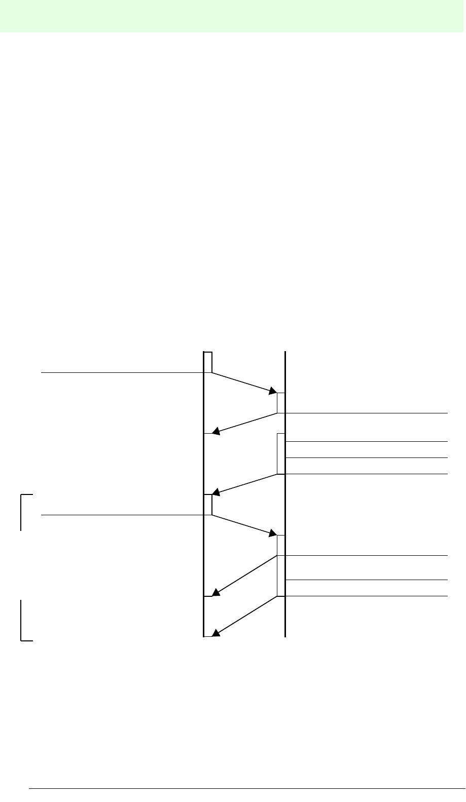
IDENT-M System V
Communication Systems
Date of issue 03.05.2001
64
Subject to reasonable modifications due to technical advances. Copyright Pepperl+Fuchs, Printed in Germany
Pepperl+Fuchs Group • Tel.: Germany (06 21) 7 76-0 • USA (330) 4 25 35 55 • Singapore 7 79 90 91 • Internet http://www.pepperl-fuchs.com
7.3 Command Stay System
7.3.1 Command Stay System + Auto Response System
Transmission Procedure:
1. The host controller sends a command to the MVI-D2-2HRX.
2. After receiving the command, the MVI-D2-2HRX sends the acknowledgement to
the host controller and stores the command.
3. The MVI-D2-2HRX trigger input is activated.
4. As long as the trigger input of the read/write head is ON, the MVI-D2-2HRX
executes the command and sends the end message to the host controller.
It is possible to execute further commands in the occasional execution system
(1à2à4) while the trigger input is active (ON).
Note: In case of commands without data carrier access, the system changes to the
occasional execution system mode, regardless of the selected communication startup
system.
Transmission Sequence
Send command (1)
Send command (1)
Send acknowledgement (5)
Send end message (4)
Execute communication command
ON signal at the trigger input (3)
Send acknowledgement (2)
Send end message (4)
Execute communication command
While the trigger input
is ON, commands can
be executed as in the
occasional execution
system.
Control interface unitHost controller
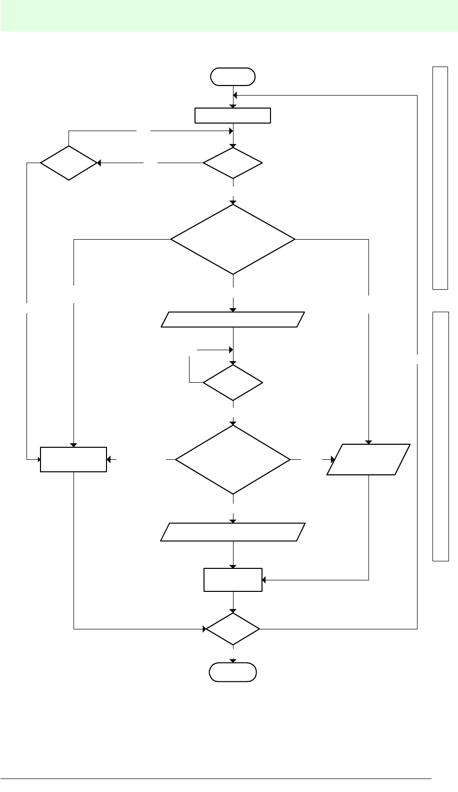
IDENT-M System V
Communication Systems
Date of issue 03.05.2001
65
Subject to reasonable modifications due to technical advances. Copyright Pepperl+Fuchs, Printed in Germany
Pepperl+Fuchs Group • Tel.: Germany (06 21) 7 76-0 • USA (330) 4 25 35 55 • Singapore 7 79 90 91 • Internet http://www.pepperl-fuchs.com
Send command (1)
START
Reset
processing
Halt
END
yes
ReceiveTime out
yes
no
Normal response ($)/
error response (%)/
other response
OK ($) error
(%)
Acknowledgement (2)
Receive
yes
Normal response ($)/
error response (%)/
other response
OK ($)
error
(%)
End of transmission (4)
Error
response
Other response
than "$" or "%"
Other response
than "$" or "%"
yes
Reset
processing
Acknowledge reception End reception
Host controller operation flow
no
no
no
Numbers (1) to (5) correspond to the
numbers of transmission procedures
already mentioned.

IDENT-M System V
Communication Systems
Date of issue 03.05.2001
66
Subject to reasonable modifications due to technical advances. Copyright Pepperl+Fuchs, Printed in Germany
Pepperl+Fuchs Group • Tel.: Germany (06 21) 7 76-0 • USA (330) 4 25 35 55 • Singapore 7 79 90 91 • Internet http://www.pepperl-fuchs.com
The following PC program was created in BASIC in order to read data:
100 ‘Read (Command Stay + Auto Response System)
110 CLS
120 OPEN"COM1:N71NN" AS#1
130 TX$="::00?10**000100004H@@ "
140 PRINT #1, TX$
150 PRINT "Send command = ";TX$
160 INPUT #1, RT$(1)
170 PRINT "Acknowledgement= ";RT$(1)
180 IF MID$(RT$(1),5,1)<>"$" GOTO 220
190 PRINT "Wait for trigger input"
200 INPUT #1,RT$(2)
210 PRINT "End message = ";RT$(2)
220 CLOSE #1
7.3.2 Command Stay System + Response Request System
Transmission Procedure
1. The host controller sends a command to the MVI-D2-2HRX.
2. After receiving the command, the MVI-D2-2HRX sends the acknowledgement to
the host controller and stores the command.
3. When the MVI-D2-2HRX trigger input is activated (ON), the MVI-D2-2HRX
executes the stored command.
4. The host controller sends an acknowledgement request in order to inquire the
result of a command.
5. After reception of the acknowledgement request, the MVI-D2-2HRX sends an end
message to the host controller, when the command execution process is finished.
• The host controller sends acknowledgement requests until the result returns from
the specified MVI-D2-2HRX station.
• The MVI-D2-2HRX has the option of executing commands in the occasional
execution system while the trigger input is active (ON). (1)à(2)à(4)à(5)
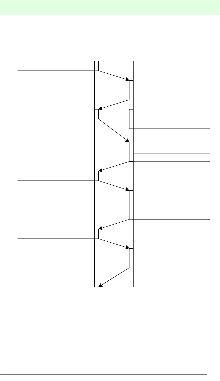
IDENT-M System V
Communication Systems
Date of issue 03.05.2001
67
Subject to reasonable modifications due to technical advances. Copyright Pepperl+Fuchs, Printed in Germany
Pepperl+Fuchs Group • Tel.: Germany (06 21) 7 76-0 • USA (330) 4 25 35 55 • Singapore 7 79 90 91 • Internet http://www.pepperl-fuchs.com
Transmission Sequence
*) When the command (1') is transmitted without sending a result request (4), the
MVI-D2-2HRX produces an “acknowledgement reception error” (EC69).
Send command (1)
Send result request (4)
Send acknowledgement (2)
Check station number
Execute command
Trigger input ON (3) *)
Send end message (5)
Check station number
Send end message (2)
Check station number
Execute command
Send end message (5’)
Check station number
Send command (1’)
Send result request (4’)
Commands can be
executed in the
occasional execution
system while the
trigger input is ON.
Control interface unitHost controller
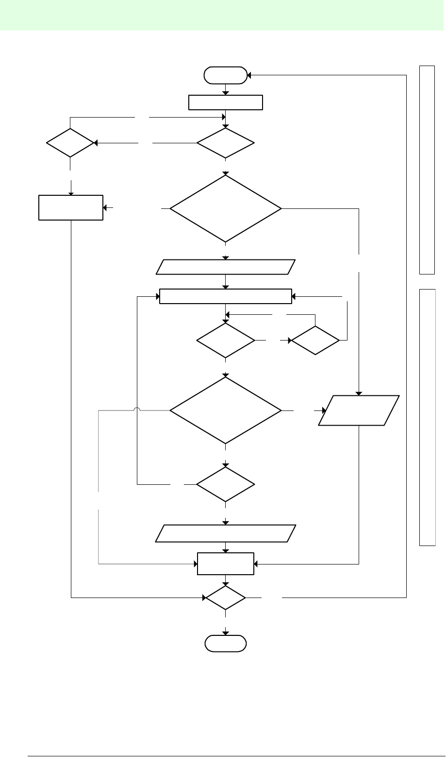
IDENT-M System V
Communication Systems
Date of issue 03.05.2001
68
Subject to reasonable modifications due to technical advances. Copyright Pepperl+Fuchs, Printed in Germany
Pepperl+Fuchs Group • Tel.: Germany (06 21) 7 76-0 • USA (330) 4 25 35 55 • Singapore 7 79 90 91 • Internet http://www.pepperl-fuchs.com
Send command (1)
START
Reset
processing
END
yes
ReceiveTime out
yes
no
OK ($)
Error
(%)
Acknowledgement (2)
Receive
yes
Normal response ($)/
error response (%)/
other response
OK ($)
Error
(%)
End of transmission (5)
Error
response
Other response
than "$" or "%"
Other response
than "$" or "%"
yes
Reset
processing
Process acknowledgement Process receives end message
Host controller operation flow
no
Normal response ($)/
error response (%)/
other response
Send acknowledgement request (4)
Operating
no
Time out
no
yes
yes
Halt
no
no
Numbers (1) to (4) correspond to the
above-mentioned numbers of trans-
mission procedures.

IDENT-M System V
Communication Systems
Date of issue 03.05.2001
69
Subject to reasonable modifications due to technical advances. Copyright Pepperl+Fuchs, Printed in Germany
Pepperl+Fuchs Group • Tel.: Germany (06 21) 7 76-0 • USA (330) 4 25 35 55 • Singapore 7 79 90 91 • Internet http://www.pepperl-fuchs.com
The following PC program was created in BASIC in order to read data:
100 ‘Read (Command Stay + Response Request System)
110 CLS
120 OPEN"COM1:N71NN" AS#1
130 TX$(1)="::00? 10* *000100004H@@ "
140 PRINT #1, TX$(1)
150 PRINT "Send command = ";TX$(1)
160 INPUT #1, RT$(1)
170 PRINT "Acknowledgement= ";RT$(1)
180 IF MID$(RT$(1),5,1)<>"$" GOTO 290
190 PRINT " Wait for trigger input"
200 TX$(2)=":00?71@@"
210 PRINT #1,TX$(2)
220 PRINT "Command acknowledgement request = ";TX$(2)
230 INPUT #1,RT$(2)
240 IF MID$(RT$(2),5,1)<>"#" GOTO 280
250 IF MID$(RT$(2),6,2)<>"71" GOTO 280
260 PRINT "Response acknowledgement request = ";RT$(2)
270 GOTO 190
280 PRINT "End message = ";RT$(2)
290 CLOSE #1
7.4 Command Register System
• When the MVI-D2-2HRX receives a command to access the data carrier, the
MVI-D2-2HRX stores this command in the system memory.
• Up to 8 transmission procedures can be stored for each read/write head. A
storage location number from 1 to 8 is allocated to each command for
transmission procedures.
• Each activation of a trigger input executes the stored function of the
corresponding number, which has been allocated by means of the 75h command.
• When the trigger input is activated, the system executes the transmission function
of the stored number allocated by the host controller.
• The occasional execution system is used for storing a transmission procedure to
the MVI-D2-2HRX system memory.

IDENT-M System V
Communication Systems
Date of issue 03.05.2001
70
Subject to reasonable modifications due to technical advances. Copyright Pepperl+Fuchs, Printed in Germany
Pepperl+Fuchs Group • Tel.: Germany (06 21) 7 76-0 • USA (330) 4 25 35 55 • Singapore 7 79 90 91 • Internet http://www.pepperl-fuchs.com
7.4.1 Command Register System + Auto Response System
Transmission Procedure
1. The host controller sends command 75h to the MVI-D2-2HRX.
2. After receiving command 75h, MVI-D2-2HRX sends an acknowledgement to the
host controller. The stored process with the corresponding number allocated by
command 75h, is executed while the trigger input is active. (System memory of
MVI-D2-2HRX: address 9010h).
3. The MVI-D2-2HRX trigger input switches ON.
4. The MVI-D2-2HRX executes the transmission function of the corresponding
storage number, allocated by command 75h and sends the end message to the
host controller.
5. With each activation of the trigger input, the transmission procedure, allocated by
command 75h, is executed (3)à(4). The host controller can only wait for reception
of the end message.
6. The next stored transmission function can be called by means of command 76h
while the trigger input is set.
• Send command 76h. (2)à(4)
• If the end message is incorrect during transmission between the host controller
and the MVI-D2-2HRX, the host controller can send the command to the MVI-D2-
2HRX for renewed execution (command 77h ). However, this function is available
only while the trigger input is active.
• In order to stop transmission while the trigger input is active, the host controller
sends a halt command (used when a MVI-D2-2HRX trigger input is active:
address 9010h = 0). Although the trigger input is active, the transmission function
is not executed.
• In order to change the transmission function, after setting the trigger input from
OFF to ON, command 75h must be sent.
Additional Description
• Command 75h
This command activates a stored transmission instruction, which is executed with
a rising edge at the trigger input. This is required, in order to send a transmission
procedure in case of a rising edge of a trigger input or a change of the
transmission function.
• Command 76h
After the transmission procedure, instructed by command 75h, has been
executed, this command enables the data transmission of the next command to
be activated, when the trigger input is in ON state. The command must be sent to
the MVI-D2-2HRX for each transmission which is executed.
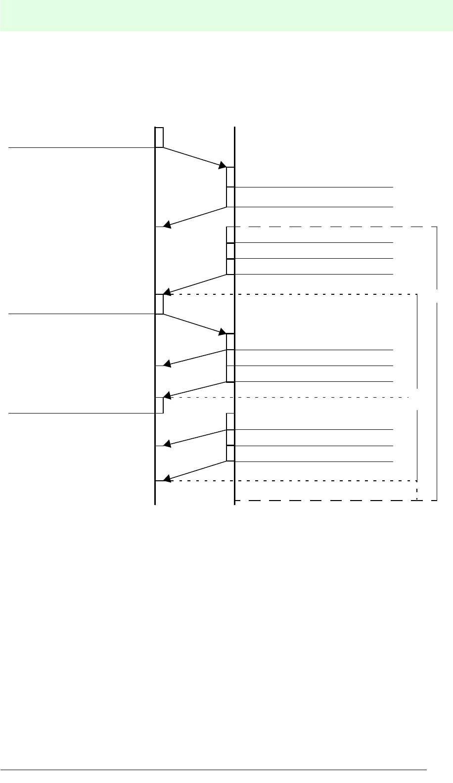
IDENT-M System V
Communication Systems
Date of issue 03.05.2001
71
Subject to reasonable modifications due to technical advances. Copyright Pepperl+Fuchs, Printed in Germany
Pepperl+Fuchs Group • Tel.: Germany (06 21) 7 76-0 • USA (330) 4 25 35 55 • Singapore 7 79 90 91 • Internet http://www.pepperl-fuchs.com
Transmission Sequence
MVI-D2-2HRXHost controller
Check station number
Send next operation
start command (1’)
Send command for
trigger input ON (1)
Send acknowledgement (2)
Send end message (4)
Execute stored command
ON signal at the trigger input (3)
Send end message (4’)
Execute stored command
Send acknowledgement (2’)
Send next operation
start command (1’’)
(A): Start next command, while trigger input is ON.
(B): Repeat at each turn ON of the trigger input.
Send end message (4’’)
Execute stored command
Send acknowledgement (2’’)
(B)
(A)
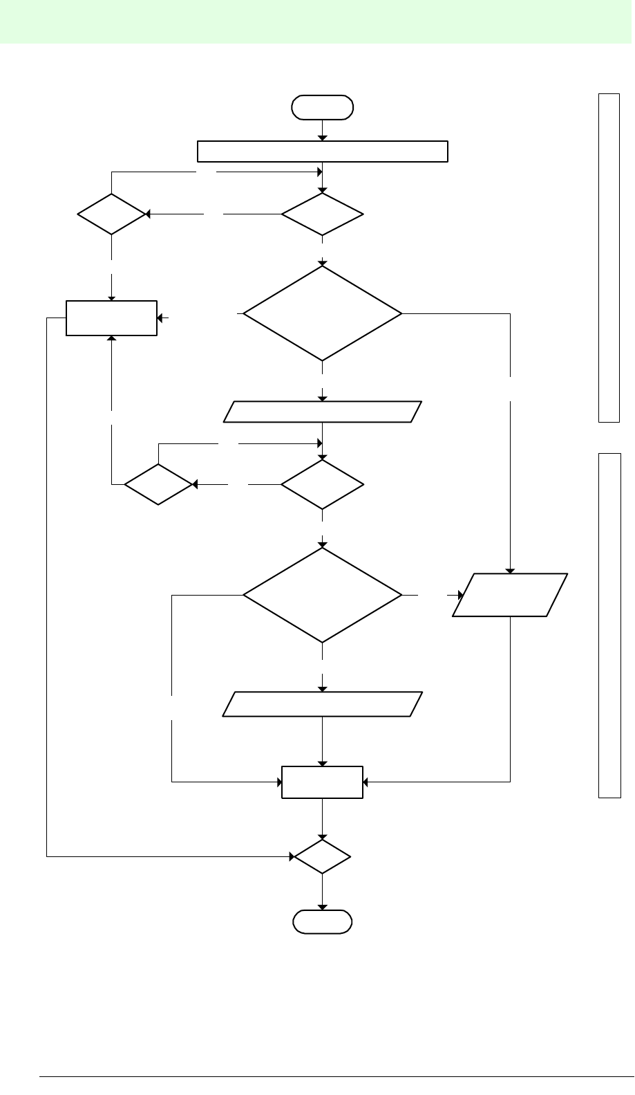
IDENT-M System V
Communication Systems
Date of issue 03.05.2001
72
Subject to reasonable modifications due to technical advances. Copyright Pepperl+Fuchs, Printed in Germany
Pepperl+Fuchs Group • Tel.: Germany (06 21) 7 76-0 • USA (330) 4 25 35 55 • Singapore 7 79 90 91 • Internet http://www.pepperl-fuchs.com
Send command when trigger input is ON (1)
START
Reset
processing
END
ReceiveTime out
yes
no
OK ($) Error
(%)
Acknowledgement (2)
Receive
yes
Normal response ($)/
error response (%)/
other response
OK ($)
Error
(%)
End of transmission (4)
Error
response
Other response
than "$" or "%"
Other response
than "$" or "%"
yes
Reset
processing
Process acknlowledgement Process receives end message
Host controller operation flow
Normal response ($)/
error rresponse (%)/
other response
Time Out no
yes
Halt
no
no
Numbers (1) to (4) correspond to
the above-mentioned numbers of
transmission procedures.

IDENT-M System V
Communication Systems
Date of issue 03.05.2001
73
Subject to reasonable modifications due to technical advances. Copyright Pepperl+Fuchs, Printed in Germany
Pepperl+Fuchs Group • Tel.: Germany (06 21) 7 76-0 • USA (330) 4 25 35 55 • Singapore 7 79 90 91 • Internet http://www.pepperl-fuchs.com
The following PC programs, for storing and executing read data, were created in
BASIC:
1. Storing read data:
100 ’Read (Command Register + Auto Response System -
Registration)
110 CLS
120 OPEN "COM1:N71NN" AS#1
130 TX$="::00?102*000100004H@@"
140 PRINT #1, TX$
150 PRINT "Send command = ";TX$
160 INPUT #1, RT$(1)
170 PRINT "Acknowledgement = ";RT$(1)
180 IF MID$(RT$(1),5,1)<>"$" GOTO 210
190 INPUT #1,RT$(2)
200 PRINT "End message = ";RT$(1)
210 CLOSE # 1
2. Executing read data:
100 ‘Read (Command Register + Auto Response System - Instruction
Execution)
110 CLS
120 OPEN"COM1:N71NN" AS#1
130 TX$="::00?752@@ "
140 PRINT #1, TX$
150 PRINT "Send command = ";TX$
160 INPUT #1, RT$(1)
170 PRINT "Acknowledgement = ";RT$(1)
180 IF MID$(RT$(1),5,1)<>"$" GOTO 230
190 PRINT "Wait for trigger input"
200 INPUT #1,RT$(2)
210 PRINT "End message = ";RT$(2)
220 IF MID$(RT$(2),5,1)="#" GOTO 190
230 CLOSE # 1

IDENT-M System V
Communication Systems
Date of issue 03.05.2001
74
Subject to reasonable modifications due to technical advances. Copyright Pepperl+Fuchs, Printed in Germany
Pepperl+Fuchs Group • Tel.: Germany (06 21) 7 76-0 • USA (330) 4 25 35 55 • Singapore 7 79 90 91 • Internet http://www.pepperl-fuchs.com
7.4.2 Command Register System + Response Request System
Transmission Procedure
1. The host controller sends the command to start the function to the MVI-D2-2HRX.
2. After receiving command 75h, the MVI-D2-2HRX returns an acknowledgement to
the host controller (the registration number of the function, allocated by command
75h, is executed while the trigger input is active; MVI-D2-2HRX system memory:
address 9010h).
3. When the trigger input of the MVI-D2-2HRX is active, the registered transmission
function, allocated by command 75h, is executed.
4. The host controller sends an acknowledgement request to the MVI-D2-2HRX, in
order to inquire the result of the operation.
5. After reception of the acknowledgement request, the MVI-D2-2HRX sends an end
message to the host controller, when the transmission procedure is finished.
6. The transmission function, allocated by command 75h, is executed (3)à(4)à(5)
whenever the trigger input is ON.
7. The transmission function, allocated by command 76h, is available (2)à(4)à(5)
while the trigger input is ON.
• Command 75h is sent, in order to change the transmission function, when the
trigger input is set from OFF to ON.
• When the end message is incorrect during transmission between the host
controller and the MVI-D2-2HRX, the host controller sends the command to the
MVI-D2-2HRX for renewed execution.
• In order to stop transmission, while the trigger input is active, the host controller
sends a halt command. (Used when a trigger input of a MVI-D2-2HRX is active:
address 9010h = 0).
• The storage process is not executed, even if the trigger input is ON.
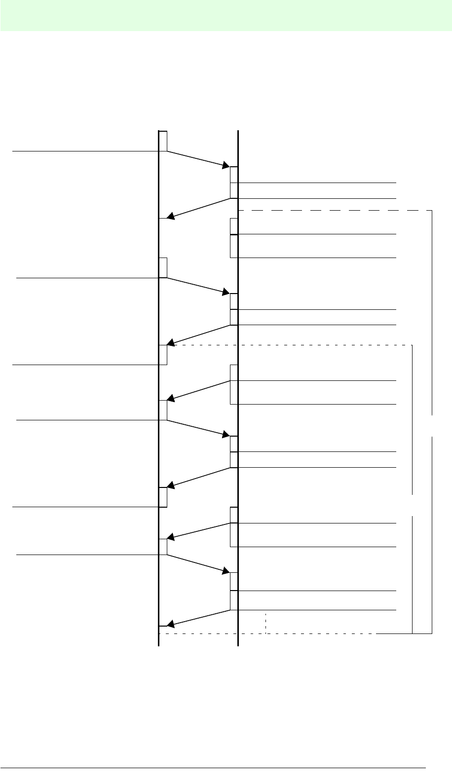
IDENT-M System V
Communication Systems
Date of issue 03.05.2001
75
Subject to reasonable modifications due to technical advances. Copyright Pepperl+Fuchs, Printed in Germany
Pepperl+Fuchs Group • Tel.: Germany (06 21) 7 76-0 • USA (330) 4 25 35 55 • Singapore 7 79 90 91 • Internet http://www.pepperl-fuchs.com
Transmission Sequence
Numbers (1) to (5) correspond to the numbers of the transmission procedures on the previous pa-
ge.
MVI-D2-2HRXHost controller
Check station number
Send next operation start
command (1’)
Send command for
trigger input ON (1)
Send acknowledgement (2’)
Send end message (5)
ON signal at the trigger input (3)
(A): A function can be started with the next command, while the trigger input is ON.
(B): Repetition with each switching of the trigger input from OFF to ON.
(A)
Execute stored command
(stored by command (1))
Check station number
Send result request (4)
Send acknowledgement (2)
Execute stored command
(stored by command (1’))
Send result request (4’)
Send end message (5’)
Check station number
Send next operation start
command (1’’)
Send acknowledgement (2’’)
Execute stored command
(stored by command (1’’))
Send result request (4’’)
Send end message (5’’)
Check station number
(B)
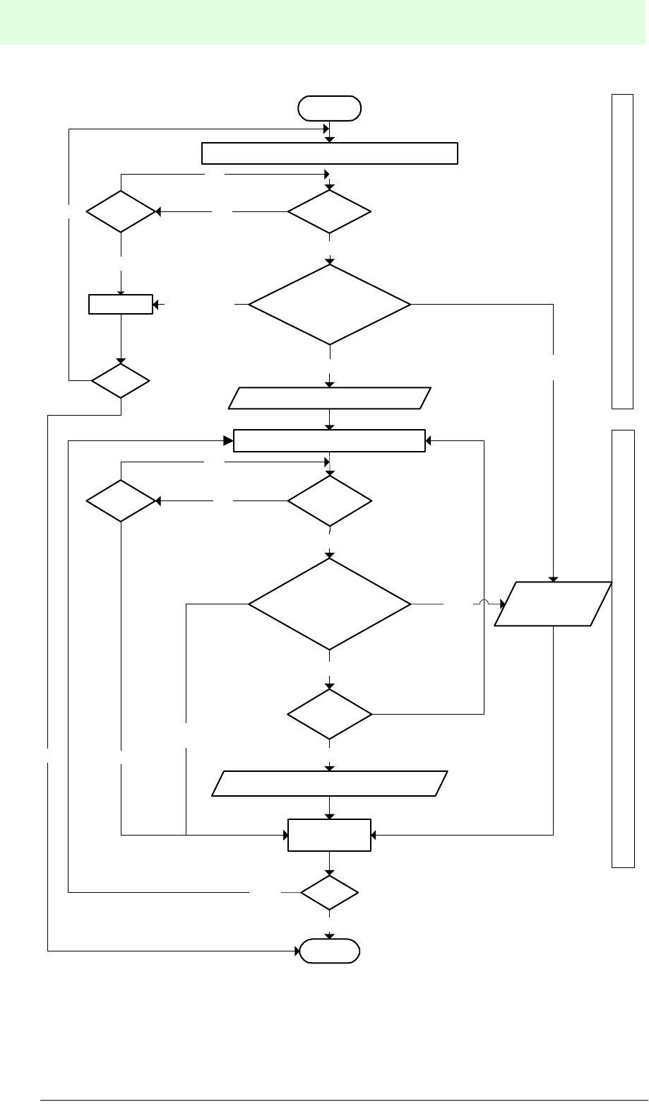
IDENT-M System V
Communication Systems
Date of issue 03.05.2001
76
Subject to reasonable modifications due to technical advances. Copyright Pepperl+Fuchs, Printed in Germany
Pepperl+Fuchs Group • Tel.: Germany (06 21) 7 76-0 • USA (330) 4 25 35 55 • Singapore 7 79 90 91 • Internet http://www.pepperl-fuchs.com
Send command for instruction execution (1)
START
Reset
END
yes
ReceiveTime out
yes
no
OK ($) Error
(%)
Acknowledgement (2)
Receive
yes
Normal response ($)/
error response (%)/
other response
OK ($)
Error
(%)
Send end of acknowledgement (5)
Error
response
Other response
than "$" or "%"
Other response
than "$" or "%"
yes
Reset
no
Process acknowledgement Process receives end message
Host controller operation flow
Normal response ($)/
error response (%)/
other response
no
yes
Halt
Halt
Time out
Operating
no
yes
Commant request (3)
no
no
no
Numbers (1) to (5) correspond to
the numbers of transmission proce-
dures already mentioned.

IDENT-M System V
Communication Systems
Date of issue 03.05.2001
77
Subject to reasonable modifications due to technical advances. Copyright Pepperl+Fuchs, Printed in Germany
Pepperl+Fuchs Group • Tel.: Germany (06 21) 7 76-0 • USA (330) 4 25 35 55 • Singapore 7 79 90 91 • Internet http://www.pepperl-fuchs.com
The following PC programs, for storing and executing read data, were created in
BASIC:
1. Reading data:
100 ’Read (Command Register + Response Request System -
Command Registration)
110 CLS
120 OPEN "COM1:N71NN" AS#1
130 TX$(1)="::00? 102*000100004H@@"
140 PRINT #1, TX$(1)
150 PRINT "Send command = ";TX$(1)
160 INPUT #1, RT$(1)
170 PRINT "Acknowledgement = ";RT$(1)
180 IF MID$(RT$(1),5,1)<>"$" GOTO 280
190 TX$(2)="::00?71@@"
200 PRINT #1, TX$(2)
210 PRINT "Command acknowledgement request = ";TX$(2)
220 INPUT #1,RT$(2)
230 IF MID$(RT$(2),5,1)<>"#" GOTO 270
240 IF MID$(RT$(2),6,2)<>"71" GOTO 270
250 PRINT "Message acknowledgement request = ";RT$(2)
260 GOTO 190
270 PRINT "End message= ";RT$(2)
280 CLOSE #1
2. Executing read data:
100 ’Read (Command Register + Response Request System -
Instruction Execution)
110 CLS
120 OPEN "COM1:N71NN" AS#1
130 TX$(1)="::00?752@@"
140 PRINT #1, TX$(1)
150 PRINT "Send command = ";TX$(2)
160 INPUT #1, RT$(1)
170 PRINT "Acknowledgement = ";RT$(1)
180 IF MID$(RT$(1),5,1)<>"$" GOTO 300
190 PRINT " Waiting for trigger input"
200 TX$(2)="::00?71@@"
210 PRINT #1,TX$(2)
220 PRINT "Command acknowledgement request = ";TX$(2)
230 INPUT #1,RT$(2)
240 IF MID$(RT$(2),5,1)<>"#" GOTO 280
250 IF MID$(RT$(2),6,2)<>"71" GOTO 280
260 PRINT "Message acknowledgement request = ";RT$(2)
270 GOTO 190
280 PRINT "End message = ";RT$(2)
290 GOTO 190
300 CLOSE # 1

IDENT-M System V
Communication Systems
Date of issue 03.05.2001
78
Subject to reasonable modifications due to technical advances. Copyright Pepperl+Fuchs, Printed in Germany
Pepperl+Fuchs Group • Tel.: Germany (06 21) 7 76-0 • USA (330) 4 25 35 55 • Singapore 7 79 90 91 • Internet http://www.pepperl-fuchs.com
7.5 Read/Write Head Scan System
The read/write head scan system supports commands for individual read/write heads
just as it successively performs the same operation for multiple read/write heads and
MVI-D2-2HRX control interface units.
• The system successively sends one token to the connected MVI-D2-2HRX
control interface unit. When a MVI-D2-2HRX has executed the desired command,
it sends an end message.
• When a MVI-D2-2HRX does not receive a response from a data carrier within a
specific time, regarding the microwave transmission, a message is sent to the
next MVI-D2-2HRX.
• The host controller waits for an end message, when it sends a command “read/
write head scan” to a MVI-D2-2HRX.
• The host controller controls the transfer time of the entire system.
• The read/write head scan system is the only system available as communication
startup system. (When attempting to perform the communication startup system
with other systems, an error is reported within the MVI-D2-2HRX).
• Response system: The auto response system as well as the response request
system are available.
Connection conditions:
• Be sure to connect the host controller to a MVI-D2-2HRX with station number “0”.
• Write the highest station number of the connected MVI-D2-2HRXs to the system
memory of the MVI-D2-2HRX number “0” (address A00Bh, one byte). Note: When
the value for the last station is set to “0”, then the system works with only one MVI-
D2-2HRX.
Setting the last station to “0”:
• Use this value in case of a connection between the host controller and a MVI-D2-
2HRX.
• Set the station number (SW3) of the MVI-D2-2HRX to “0”.
• Operation: The number “0” control interface unit, keeps repeating the
transmission procedure until one of the two read/write heads communicates with
the data carrier.
• When using only one control interface unit, the RS 232C as well as the RS 422
interface standards are available via the corresponding terminal block and
connector. In case of multiple control interface units, the RS 422 interface should
be used.

IDENT-M System V
Communication Systems
Date of issue 03.05.2001
79
Subject to reasonable modifications due to technical advances. Copyright Pepperl+Fuchs, Printed in Germany
Pepperl+Fuchs Group • Tel.: Germany (06 21) 7 76-0 • USA (330) 4 25 35 55 • Singapore 7 79 90 91 • Internet http://www.pepperl-fuchs.com
.
7.5.1 Read/Write Head System + Auto Response System
(between the host controller and the MVI-D2-2HRX with station number “0”)
Transmission Procedure
1. The host controller sends a “read/write head scan” command to the MVI-D2-
2HRX with station number “0”.
2. After receiving the command “read/write head scan”, the MVI-D2-2HRX number
“0” sends an acknowledgement to the host controller.
3. After having received the acknowledgement, the host controller waits for the end
message.
4. The MVI-D2-2HRX executes the function “read/write head scan” for all read/write
heads from station number “0” to the last station number.
5. When the MVI-D2-2HRX has completed the transmission procedure with the data
carriers, station number “0” sends the end message including the MVI-D2-2HRX
station number and the number of the read/write head, which had executed the
function, to the host controller.
• Each MVI-D2-2HRX executes transmission functions from read/write head
number “0” to read/write head number “1”.
• The token is sent to the next MVI-D2-2HRX, provided that there was no data
carrier error, no read/write head error and no MVI-D2-2HRX error.
• In addition to the read/write head scan mode, the host controller can send other
communication commands to any control interface unit.
Commands available for the read/write head scan system:
Read:
Read (10h), read and check (11h), read the ID-code (12h), read data
carrier to the MVI-D2-2HRX (13h), read and check the data carrier to the
MVI-D2-2HRX (14h)
Write: Write (20h), write and check (21h), write ID-code (22h)
Clear: Clear (30h), initialise data carrier (31h)
Diagnosis: Self-diagnosis of data carrier (50h), ROM check (51h), RAM check (52h),
check battery life of data carrier (53h), block check (60h)
The numbers in brackets denote the command code.
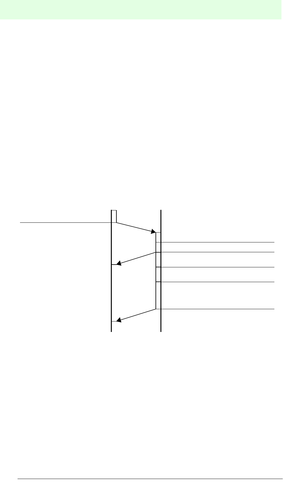
IDENT-M System V
Communication Systems
Date of issue 03.05.2001
80
Subject to reasonable modifications due to technical advances. Copyright Pepperl+Fuchs, Printed in Germany
Pepperl+Fuchs Group • Tel.: Germany (06 21) 7 76-0 • USA (330) 4 25 35 55 • Singapore 7 79 90 91 • Internet http://www.pepperl-fuchs.com
Note:
• Station number “0” is required for transmission to the host controller (e.g.
personal computer) as well as to the MVI-D2-2HRX.
• The read/write head scan procedure starts with the station number following the
previous operation as well as the read/write head number of the previous
operation.
Ex. 1: When the scanning ends with station number “1”, and read/write head number
“1” executes the last operation, the operation is restarted with station number “2” and
read/write head number “0”.
Ex. 2: When the scanning ends with station number “1”, and read/write head number
“0” executes the last operation, the operation is restarted with station number “1” and
read/write head number “1”.
Transmission Sequence
Send command (1)
End of transmission procedure with the
data carrier
Send acknowledgement (2)
Check station number
(station number “0”)
Send token of the transmission from
station number “0” to “N”.
Send end message (5) (including the
station number and the read/write head
numbers of the closed function and the
data carrier)
MVI-D2-2HRX of station number “0”Host controller
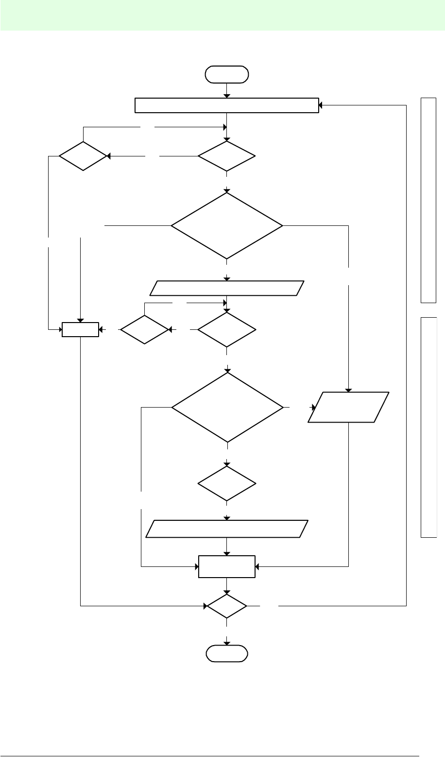
IDENT-M System V
Communication Systems
Date of issue 03.05.2001
81
Subject to reasonable modifications due to technical advances. Copyright Pepperl+Fuchs, Printed in Germany
Pepperl+Fuchs Group • Tel.: Germany (06 21) 7 76-0 • USA (330) 4 25 35 55 • Singapore 7 79 90 91 • Internet http://www.pepperl-fuchs.com
Emit sending (for read/write head scan) (1)
START
Reset
END
yes
ReceiveTime out
yes
no
OK ($) Error
(%)
Acknowledgement (2)
Receive
yes
Normal response ($)/
error response (%)/
other response
OK ($)
Error
(%)
Send end of acknowledgement (5)
Error
response
Other response
than "$" or "%"
Other response
than "$" or "%"
yes
Processing of the acknowledgement Processing of the acknowledgement
Host controller operation flow
Normal response ($)/
error response (%)/
other response
no
Halt
Time out
Operating
no
yes
Reset
no
no
no
Numbers (1) to (5) correspond to
the numbers of transmission proce-
dures already mentioned.

IDENT-M System V
Communication Systems
Date of issue 03.05.2001
82
Subject to reasonable modifications due to technical advances. Copyright Pepperl+Fuchs, Printed in Germany
Pepperl+Fuchs Group • Tel.: Germany (06 21) 7 76-0 • USA (330) 4 25 35 55 • Singapore 7 79 90 91 • Internet http://www.pepperl-fuchs.com
The following PC program was created in BASIC in order to read data:
100 ‘Read (Read/Write Head Scan + Auto Response System)
110 CLS
120 OPEN"COM1:N71NN" AS#1
130 TX$="::0*?10**000100004H@@ "
140 PRINT #1, TX$
150 PRINT "Send command = ";TX$
160 INPUT #1, RT$(1)
170 PRINT "Acknowledgement = ";RT$(1)
180 IF MID$(RT$(1),5,1)<>"$" GOTO 220
190 PRINT "While scanning (wait for reception of end message)"
200 INPUT #1,RT$(2)
210 PRINT "End message = ";RT$(2)
220 CLOSE #1
7.5.2 Read/Write Head System + Response Request System
Transmission Procedure
1. The host controller sends a “read/write head scan” command to the MVI-D2-
2HRX number “0”.
2. After receiving the command “read/write head scan”, station number “0” sends an
acknowledgement to the host controller.
3. The MVI-D2-2HRX excutes the function “read/write head scan” for all read/write
heads from station number “0” to the last station number.
4. After receiving the acknowledgement, the host controller sends a result request
to station number “0”.
5. After receiving the function request from the host controller, the MVI-D2-2HRx
sends the end message including the MVI-D2-2HRX station number and the
number of the read/write head, which has executed the function, to station
number “0”.
• The host controller keeps sending acknowledgement requests until the result
returns from station number “0”.
• Each MVI-D2-2HRX executes transmission functions from read/write head
number “0” to read/write head number “1”.
• The token is sent to MVI-D2-2HRX, provided that there was no data carrier error,
no read/write head error and no MVI-D2-2HRX error.
• Further transmission procedures with the MVI-D2-2HRX (station number “n”),
which executes the transmission function via read/write head scan, are available
to the host controller.
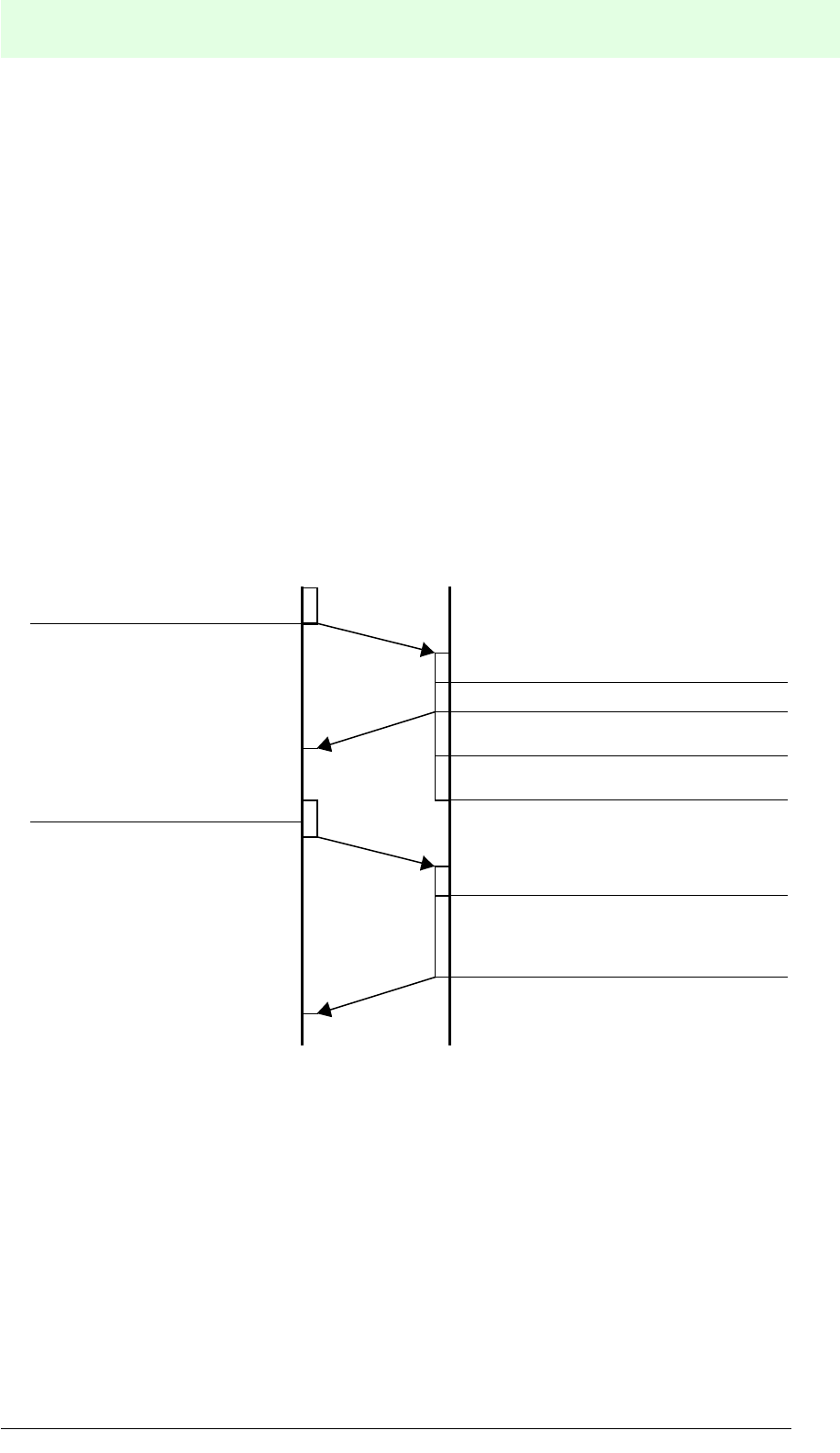
IDENT-M System V
Communication Systems
Date of issue 03.05.2001
83
Subject to reasonable modifications due to technical advances. Copyright Pepperl+Fuchs, Printed in Germany
Pepperl+Fuchs Group • Tel.: Germany (06 21) 7 76-0 • USA (330) 4 25 35 55 • Singapore 7 79 90 91 • Internet http://www.pepperl-fuchs.com
Note:
• Station number “0” is required for the transmission to the host controller and to
the MVI-D2-2HRX.
• The read/write head scan procedure starts with the next station number and the
next read/write head number of the last operation.
Ex. 1: When the scanning ends with station number “1”, and read/write head number
“1” executes the last operation, the operation is restarted with station number “2” and
read/write head number “0”.
Ex. 2: When the scanning ends with station number “1”, and read/write head number
“0” executes the last operation, the operation is restarted with station number “1” and
read/write head number “1”.
Numbers (1) to (5) correspond to the number of the transmission procedure on the previous page.
Send command (1)
End of transmission procedure with the
data carrier
Send acknowledgement (2)
Check station number
(station number “0”)
Send token of the transmission from
station number “0” to “n”.
Send end message (5) (including the
station number, and the read/write head
numbers of the closed function and the
data carrier)
Send command (1)
Check station number (#0)
MVI-D2-2HRXHost controller
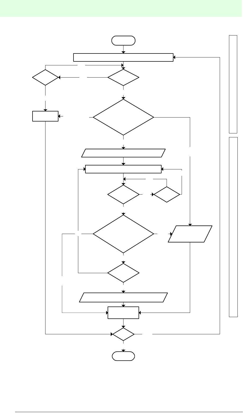
IDENT-M System V
Communication Systems
Date of issue 03.05.2001
84
Subject to reasonable modifications due to technical advances. Copyright Pepperl+Fuchs, Printed in Germany
Pepperl+Fuchs Group • Tel.: Germany (06 21) 7 76-0 • USA (330) 4 25 35 55 • Singapore 7 79 90 91 • Internet http://www.pepperl-fuchs.com
Emit sending (for read/write head scan) (1)
START
Reset
END
yes
Receive
yes
no
OK ($)
Error
(%)
Acknowledgement (2)
Receive
yes
Normal response ($)/
error response (%)/
other response
OK ($)
Error
(%)
Send end of acknowledgement (5)
Error
response
Other response
than "$" or "%"
Other response
than "$" or "%"
Processing of the acknowledgement Processing of the acknowledgement
Host controller operation flow
Normal response ($)/
error response (%)/
other response
no
Halt
Time out
Operating
no
no
Send result request (4)
Time out
yes
yes
Reset
yes
no
no
Numbers (1) to (5) correspond to the
numbers of transmission procedures
already mentioned.
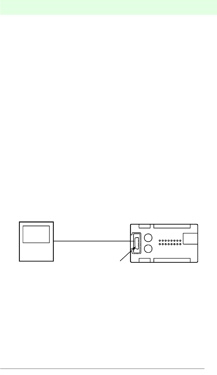
IDENT-M System V
Communication Systems
Date of issue 03.05.2001
85
Subject to reasonable modifications due to technical advances. Copyright Pepperl+Fuchs, Printed in Germany
Pepperl+Fuchs Group • Tel.: Germany (06 21) 7 76-0 • USA (330) 4 25 35 55 • Singapore 7 79 90 91 • Internet http://www.pepperl-fuchs.com
The following PC program was created in BASIC in order to read data:
100 ‘Read (Read/Write Head Scan + Response Request System)
110 CLS
120 OPEN "COM1:N71NN" AS#1
130 TX$(1)="::0*?10**000100004H@@"
140 PRINT #1, TX$(1)
150 PRINT "Send command = ";TX$(1)
160 INPUT #1, RT$(1)
170 PRINT "Acknowledgement = ";RT$(1)
180 IF MID$(RT$(1),5,1)<>"$" GOTO 290
190 PRINT "While scanning (wait for reception of end message)"
200 TX$(2)="::0*?71@@"
210 PRINT #1,TX$(2)
220 PRINT "Command acknowledgement request = ";TX$(2)
230 INPUT #1,RT$(2)
240 IF MID$(RT$(2),5,1)<>"#" GOTO 280
250 IF MID$(RT$(2),6,2)<>"71" GOTO 280
260 PRINT "Message acknowledgement request = ";RT$(2)
270 GOTO 190
280 PRINT "End message = ";RT$(2)
290 CLOSE #1
7.5.3 Connection Example
Connection of a host controller to an MVI-D2-2HRX connector with RS 232C.
Adjusting the MVI-D2-2HRX switches: SW1-5 to OFF, SW1-6 to OFF, and SW1-7 to
OFF.
In case the last station number is higher than “0”:
The host controller provides a one-to-one connection to MVI-D2-2HRX station
number “0”, and scans between multiple MVI-D2-2HRXs.
Connection
1. Connect the host controller to an RS 422 connector of the MVI-D2-2HRX station
number “0”.
2. Connect each output in parallel via an RS 422, between multiple MVI-D2-2HRX.
3. The MVI-D2-2HRX station number “0” is used as host controller among the
connected MVI-D2-2HRX.
RS 232C
Host
controller
Connector
MVI-D2-2HRX number “0”
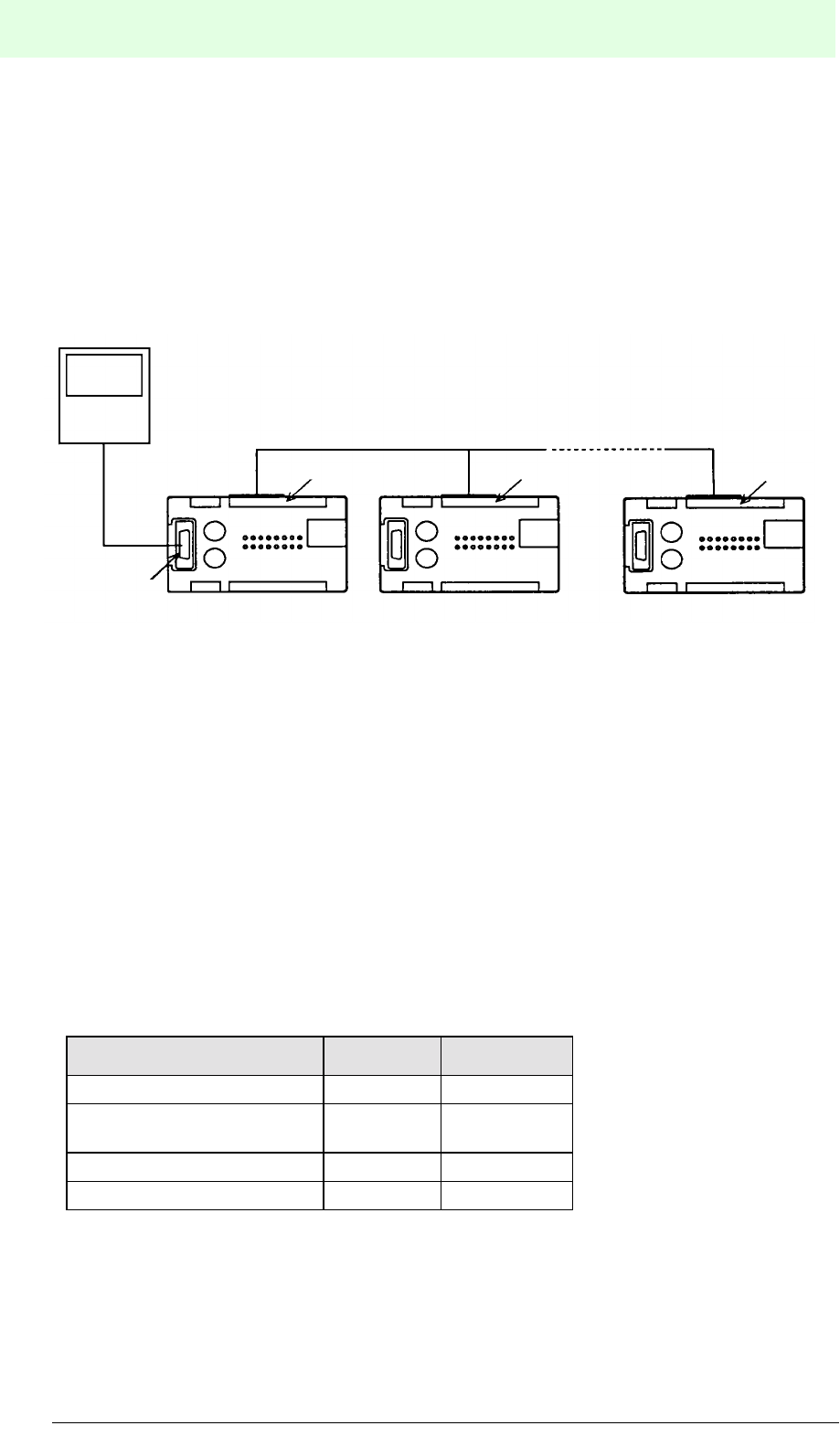
IDENT-M System V
Communication Systems
Date of issue 03.05.2001
86
Subject to reasonable modifications due to technical advances. Copyright Pepperl+Fuchs, Printed in Germany
Pepperl+Fuchs Group • Tel.: Germany (06 21) 7 76-0 • USA (330) 4 25 35 55 • Singapore 7 79 90 91 • Internet http://www.pepperl-fuchs.com
Switch Setting
Only the following switch settings are available:
SW1-5: set to OFF at all stations (type of connection: personal computer with serial
interface).
SW1-6: OFF and SW1-7: ON for RS 422 connection (2-wire system), SW1-6 to ON
and SW1-7 to OFF for RS 422 connection (4-wire system).
Connection Diagram
Transmission Specification
1. Between the host controller and the MVI-D2-2HRX with station number “0”:
Adjust switch SW1-1 to SW1-4 and SW2.
2. MVI-D2-2HRX (station number “0”)
Terminal block connection: 19200 baud, 8 data bit, odd parity, one stop bit (fixed
setting). Note: Automatically set in the MVI-D2-2HRX (adjustment does not have
to be reset).
3. From the MVI-D2-2HRX (next station after station number “0”) to the last MVI-D2-
2HRX station (between MVI-D2-2HRX control interface units):
Terminal block connection: 19200 baud, 8 data bit, odd parity, one stop bit (fixed
setting). Note: Automatically set in the MVI-D2-2HRX.
Transmission Specification Switch Setting
8 Data bits SW1-1 ON
Odd parity SW1-2
SW1-3
ON
ON
Stop bit as 1 SW1-4 OFF
19200 bps SW2 6
Terminal block Terminal block Terminal block
MVI-D2-2HRX
Number “0”
MVI-D2-2HRX
Number “1” MVI-D2-2HRX
Number “n”
(n=0 ... Fh)
RS 422
RS 422
Connector

IDENT-M System V
Communication Systems
Date of issue 03.05.2001
87
Subject to reasonable modifications due to technical advances. Copyright Pepperl+Fuchs, Printed in Germany
Pepperl+Fuchs Group • Tel.: Germany (06 21) 7 76-0 • USA (330) 4 25 35 55 • Singapore 7 79 90 91 • Internet http://www.pepperl-fuchs.com
Operation
1. When MVI-D2-2HRX on station number “0” cannot receive a message from the
data carrier after a certain number of repetitions, MVI-D2-2HRX number “0”
transmits a token to the next and the following stations.
2. When the last MVI-D2-2HRX station cannot receive a message from the data
carrier, the last station transmits a token to station number “0”.
3. When an MVI-D2-2HRX successfully transmits data to a data carrier, MVI-D2-
2HRX station number “0” returns an end message to the host controller.
Note:
As soon as the operation is completed, the next scanning starts with the next station
and the next read/write head.
7.6 Simultaneous Processing of Commands
7.6.1 With One Read/Write Head
When the MVI-D2-2HRX receives the second command before sending the end
message for the first command, two commands are processed in one read/write head
and an error message (error at command execution) is sent in response to the second
command.
Note: Based on the error code, the host controller identifies to which commands the
error messages belong. The host controller is able to distinguish unambiguously
between the error code, generated by executing the first command, and the error
code of the second command. (Error at executing a command).
The MVI-D2-2HRX does not cancel the first command and executes the transmission
procedure. Then the following acknowledgement is sent:
1. Auto response system: Return end message during a process such as a data
carrier access.
2. Response request system: After a process, such as a data carrier access has
been accomplished, the end message is returned after receiving the result
request.
This applies to both the occasional execution system and the command stay system.
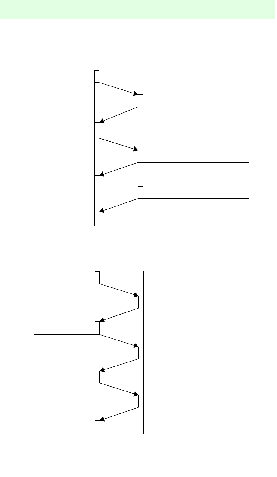
IDENT-M System V
Communication Systems
Date of issue 03.05.2001
88
Subject to reasonable modifications due to technical advances. Copyright Pepperl+Fuchs, Printed in Germany
Pepperl+Fuchs Group • Tel.: Germany (06 21) 7 76-0 • USA (330) 4 25 35 55 • Singapore 7 79 90 91 • Internet http://www.pepperl-fuchs.com
Auto Response System:
Response Request System:
Send acknowledgement for command
(1)
MVI-D2-2HRXHost controller
Send error message for command (2)
Send end message command (1)
Send command (1)
Send command (2)
Send acknowledgement for command
(1)
MVI-D2-2HRXHost controller
Send error message for command (2)
Send end message of command (1)
Send command (1)
Send command (2)
Send result request
(1)
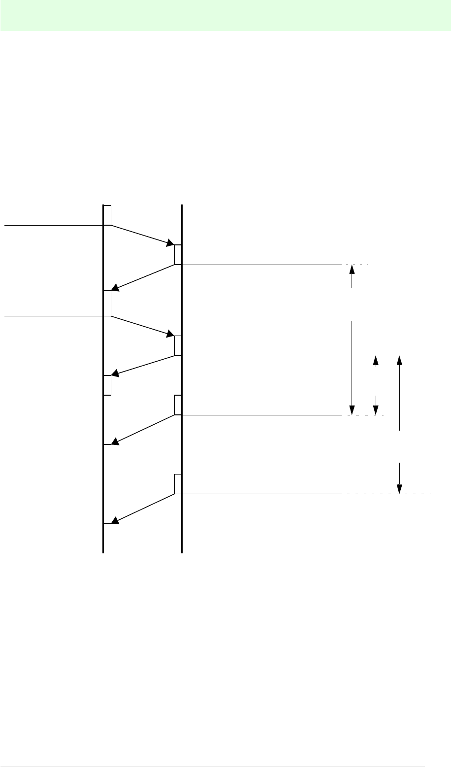
IDENT-M System V
Communication Systems
Date of issue 03.05.2001
89
Subject to reasonable modifications due to technical advances. Copyright Pepperl+Fuchs, Printed in Germany
Pepperl+Fuchs Group • Tel.: Germany (06 21) 7 76-0 • USA (330) 4 25 35 55 • Singapore 7 79 90 91 • Internet http://www.pepperl-fuchs.com
7.6.2 With Two Different Read/Write Heads
When two read/write heads are connected to the MVI-D2-2HRX, the host can send a
command to one channel while the other channel provides communication between
the read/write head and the data carrier.
Transmission Sequence with Auto Response System:
Simul-
taneous
Send acknowledgement (2)
(Read/write head 0)
MVI-D2-2HRXHost controller
Send acknowledgement (2')
(Read/write head 1)
Send end message (3)
(Read/write head 0)
Send end message (3)
(Read/write head 1)
Send command (1)
(Read/write head 0)
Send command (1')
(Read/write head 1)
Microwave transmission
between read/write head 0
and data carrier
Microwave transmission
between read/write head
1 and data carrier
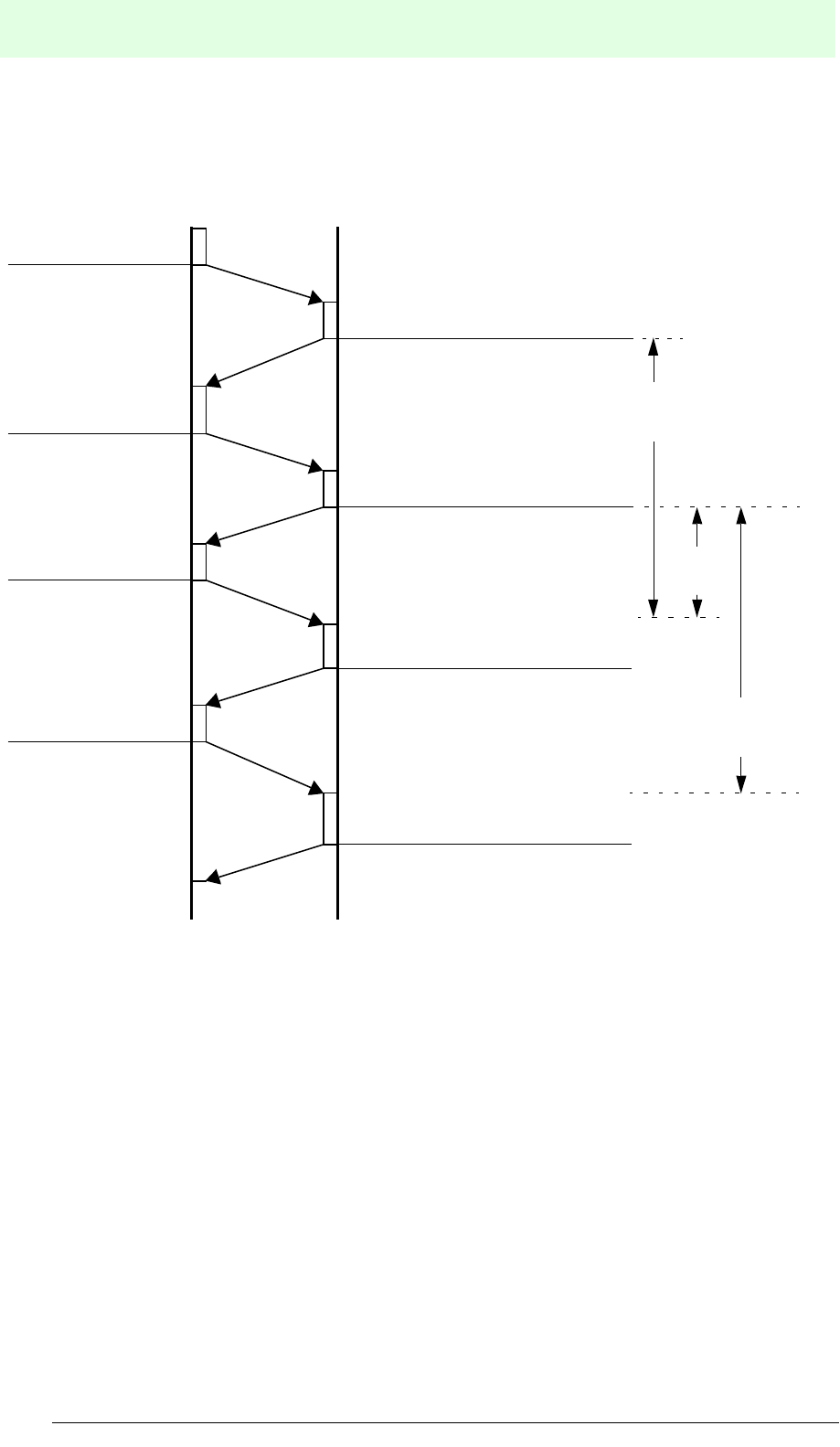
IDENT-M System V
Communication Systems
Date of issue 03.05.2001
90
Subject to reasonable modifications due to technical advances. Copyright Pepperl+Fuchs, Printed in Germany
Pepperl+Fuchs Group • Tel.: Germany (06 21) 7 76-0 • USA (330) 4 25 35 55 • Singapore 7 79 90 91 • Internet http://www.pepperl-fuchs.com
Transmission Sequence of the Response Request System:
Simul-
taneous
Send acknowledgement (2)
(Read/write head 0)
MVI-D2-2HRXHost controller
Send acknowledgement (2')
(Read/write head 1)
Send end message (3)
(Read/write head 0)
Send end message (3)
(Read/write head 1)
Send command (1)
(Read/write head 0)
Send command (1')
(Read/write head 1)
Microwave transmission
between read/write head 0
and data carrier
Microwave transmission
between read/write head 1 and
data carrier
Send result request
(Read/write head 0)
Send result request
(Read/write head 1)

IDENT-M System V
Communication Systems
Date of issue 03.05.2001
91
Subject to reasonable modifications due to technical advances. Copyright Pepperl+Fuchs, Printed in Germany
Pepperl+Fuchs Group • Tel.: Germany (06 21) 7 76-0 • USA (330) 4 25 35 55 • Singapore 7 79 90 91 • Internet http://www.pepperl-fuchs.com
7.6.3 Description
• When the microwave communication of read/write head 0 and read/write head 1
is doubled, the MVI-D2-2HRX performs simultaneous processing for both read/
write heads.
• Each response return system has a different end message.
1. Auto response system: Acknowledgement from the first channel, that has
completed the microwave transmission.
2. Response request system: The first channel to receive an acknowledgement
request returns an acknowledgement after executing the microwave
transmission.
• Since the commands, acknowledgements, result requests and end messages
have a read/write head number, the host controller is able to identify the read/
write head number.
• Make sure that the command for the second read/write head is not transmitted
until the acknowledgement for the first read/write head has been received and
vice versa. When the acknowledgement of one channel collides with the
command of another channel, the MVI-D2-2HRX can neither receive the
command (command (1) of read/write head 1) nor execute the function.

IDENT-M System V
Transmission Procedure
Date of issue 03.05.2001
92
Subject to reasonable modifications due to technical advances. Copyright Pepperl+Fuchs, Printed in Germany
Pepperl+Fuchs Group • Tel.: Germany (06 21) 7 76-0 • USA (330) 4 25 35 55 • Singapore 7 79 90 91 • Internet http://www.pepperl-fuchs.com
8 Transmission Procedure
8.1 Overview
Two types of transmission functions can be distinguished: “Communication with data
carrier”, such as transmission between the host and the data carriers, as well as
between MVI-D2-2HRX control interface units and data carriers; and “MVI-D2-2HRX
access function”, which represents transmission between the host controller and the
MVI-D2-2HRX.
The MVI-D2-2HRX has a data carrier buffer for each read/write head which is in the
same memory area as the data carriers are. (The MVI-D2-2HRX has the same
address structure as the data carrier.)
The command register system allows only commands that access data carriers to be
stored as transmission procedure. Commands which only access the control interface
unit, cannot be stored in the command register system.
Transmission
procedure
Command
code
(Hex.)
Data
transm.
direction
Classifi-
cation1) Description
Read
Read 1 0 (-1) P Read in data carrier data to the host
controller
Read and
check 1 1 (-1) P
Read data carrier twice. The data is
transmitted to the host controller, after
checking the first and the second data.
Read
ID code 1 2 (-1) P
Read in ID code of the data carrier to the
host controller (data carrier address: 8040h
to 8043h).
Read in data
carrier to the
MVI-D2-2HRX
1 3 (-3) P Read in data of data carrier to MVI-D2-
2HRX data carrier buffer.
Read and check
data from data
carrier to
MVI-D2-2HRX
1 4 (-3) P
Read data carrier twice. The data is stored
in the MVI-D2-2HRX data carrier buffer,
after the first and the second data is
checked.
Read
MVI-D2-2HRX 1 5 (-5) C Send MVI-D2-2HRX data from the data
carrier memory to the host controller.
Read current
time 1 6 (-5) C
Read current time (year, month, week-day,
hour, second) from the clock integrated in
the MVI-D2-2HRX.
1) Shows the classification of the transmission procedure. Commands identified by the letter P
access the data carriers. Commands identified by the letter C access the MVI-D2-2HRX.

IDENT-M System V
Transmission Procedure
Date of issue 03.05.2001
93
Subject to reasonable modifications due to technical advances. Copyright Pepperl+Fuchs, Printed in Germany
Pepperl+Fuchs Group • Tel.: Germany (06 21) 7 76-0 • USA (330) 4 25 35 55 • Singapore 7 79 90 91 • Internet http://www.pepperl-fuchs.com
Write
Write 2 0 (-2) P Write data from the host to the data carrier.
Write and check 2 1 (-2) P
The data is read and checked after writing it
from the host controller to the data carriers.
(Read-after-write system)
Write with ID
code 2 2 (-2) P Write ID code to data carriers (data carrier
address: 8040h to 8043h)
Write from MVI-
D2-2HRX to
data carrier
2 3 (-4) P Write the data stored in the MVI-D2-2HRX
data carrier buffer to the data carriers.
Write and check
from the MVI-
D2-2HRX to the
data carriers
2 4 (-6) C
The data, stored in the data carrier buffer of
the MVI-D2-2HRX, is first written, then read
and checked. (Read-after-write system)
Write from host
controller to
MVI-D2-2HRX
2 5 (-6) C
Store data from the host controller to the
system memory and the data carrier buffer
of the MVI-D2-2HRX.
Set the current
time 2 6 (-6) C
Set right the time (year, month, week-day,
hour, second) of the clock integrated in the
MVI-D2-2HRX.
Clear
Clear 3 0 (-2) P Write the same data into a specified area of
the data carrier.
Initialisation of
the data carrier 3 1 (-2) P Initialise data area of data carrier and
system area.
Clear MVI-D2-
2HRX memory 3 5 (-6) C
Write the same data into a specified area
such as the data carrier buffer of the MVI-
D2-2HRX.
Initialisation of
MVI-D2-2HRX 3 6 (-6) C Initialise data of data carrier buffer and
system memory of MVI-D2-2HRX.
Clear protocol
(transmission
time, number of
transmission,
error protocol)
3 7 (-6) C
Clear transmission time, transmission
number and error protocol of the MVI-D2-
2HRX system area.
Copy
Copy with
different read/
write heads
4 0 (3)à(4) P
Copy the data from a data carrier facing a
read/write head to another data carrier
facing the other read/write head.
Copy and check
using different
read/write
heads
4 1 (3)à(4) P
Read data carrier facing a read/write head
twice, check these two data, and copy them
to the other read/write head, facing the
opposite read/write head. Then read and
check.
Transmission
procedure
Command
code
(Hex.)
Data
transm.
direction
Classifi-
cation1) Description
1) Shows the classification of the transmission procedure. Commands identified by the letter P
access the data carriers. Commands identified by the letter C access the MVI-D2-2HRX.

IDENT-M System V
Transmission Procedure
Date of issue 03.05.2001
94
Subject to reasonable modifications due to technical advances. Copyright Pepperl+Fuchs, Printed in Germany
Pepperl+Fuchs Group • Tel.: Germany (06 21) 7 76-0 • USA (330) 4 25 35 55 • Singapore 7 79 90 91 • Internet http://www.pepperl-fuchs.com
Diagnostic
Self-diagnosis
of data carriers 5 0 - P Diagnosis of ROM, RAM and battery life of
data carrier.
ROM check 5 1 - P Diagnosis of ROM in data carrier
RAM check 5 2 - P Diagnosis of RAM in data carrier (area
adjustable)
Check battery
life of data
carrier
5 3 - P Diagnosis of battery life of data carrier
(checks battery voltage and service life).
Self-diagnosis
of MVI-D2-
2HRX
5 5 - C Diagnosis of ROM, RAM and battery life of
MVI-D2-2HRX
Block check 6 0 - P
Check whether the data stored on the data
carrier is correct, by using the block check
code.
Other
Reset 7 0 - C
• Stop the currently executed transmission
procedure.
• Reset error state of MVI-D2-2HRX.
Request
command
response
7 1 - C
If the response request system is applied,
an acknowledgement request is transmitted
to the MVI-D2-2HRX.
Set outputs 7 2 - C Switch ON or OFF outputs 0 ... 3.
Read status 7 3 - C Read MVI-D2-2HRX status.
Stop command 7 4 - C
• Instruction to stop transmission function
stored in the MVI-D2-2HRX using the
command register system.
• Instruction to stop the read/write head
scan function.
Calling a
registered
command
7 5 - C
[Command register system]
Instruction to start the stored command,
when the trigger input is set to ON (allocate
storage number likewise).
Calling the
registered
command
7 6 - C
[Command register system]
Instruction to start the function after ending
the function triggered by the next command
75h . Simultaneous execution of functions is
possible. (Operating status: Trigger input
remains active.)
Repeat
command 7 7 - C
[Command register system]
The host controller requests repeated
execution of the previous command (e.g.:
faulty transmission of end message).
Transmission
procedure
Command
code
(Hex.)
Data
transm.
direction
Classifi-
cation1) Description
1) Shows the classification of the transmission procedure. Commands identified by the letter P
access the data carriers. Commands identified by the letter C access the MVI-D2-2HRX.

IDENT-M System V
Transmission Procedure
Date of issue 03.05.2001
95
Subject to reasonable modifications due to technical advances. Copyright Pepperl+Fuchs, Printed in Germany
Pepperl+Fuchs Group • Tel.: Germany (06 21) 7 76-0 • USA (330) 4 25 35 55 • Singapore 7 79 90 91 • Internet http://www.pepperl-fuchs.com

IDENT-M System V
Transmission Procedure
Date of issue 03.05.2001
96
Subject to reasonable modifications due to technical advances. Copyright Pepperl+Fuchs, Printed in Germany
Pepperl+Fuchs Group • Tel.: Germany (06 21) 7 76-0 • USA (330) 4 25 35 55 • Singapore 7 79 90 91 • Internet http://www.pepperl-fuchs.com
8.1.1 Verification
When the two verified data differ, the MVI-D2-2HRX treats this as a verification error.
The address of the differing data is included in the error message. If an error, e.g. a
data transmission error occurs during “read and check”, the end address of the write
data is likewise attached to the error message.
8.1.2 Copy
The copy command reads data of a specified range of the data carrier which is facing
the read/write head and writes them into the data carrier, which is facing the other
read/write head. In order to accelerate data processing time, this function is executed
in the MVI-D2-2HRX without data storage in the connected host controller.
1. Usable memory area of the data carrier
• Data area MVC-60-64K: 7552 bytes
• Data area MVC-60-256K: 31 kbyte
2. When instructing to copy data, enter the read/write head number from which the
data should be read.
3. When ID code allocations are used, the ID code of the data carrier which has to
be recorded, must be specified.
4. Applications
• When a workpiece reaches the end of the production line and is then placed on
another pallet for the next process, the data should be copied from one data
carrier to the data carrier of the next process, in order to keep current processing
and information running.
• All data stored in the data carrier must be copied before the batteries are
exhausted.
8.1.3 Block Check
This function checks whether the data of the data carrier have only changed due to
write, clear and copy commands. This command divides the data area and the system
area of the data carrier (see the following table) and checks all blocks from the start
block to the following blocks for errors.
Example: This function checks block 1 and block 2, when 007Fh is set as starting
address and the byte number is two byte. When any error is found in these blocks,
the MVI-D2-2HRX treats this as a block check error.

IDENT-M System V
Transmission Procedure
Date of issue 03.05.2001
97
Subject to reasonable modifications due to technical advances. Copyright Pepperl+Fuchs, Printed in Germany
Pepperl+Fuchs Group • Tel.: Germany (06 21) 7 76-0 • USA (330) 4 25 35 55 • Singapore 7 79 90 91 • Internet http://www.pepperl-fuchs.com
.
8.1.4 Self-Diagnosis of the Data Carrier
In normal operation the data carrier performs a self-diagnosis. The diagnosis is
carried out in the following order: ROM check, RAM check and data carrier battery life
check. These three checks are also available individually.
8.1.5 ROM Check
This check determines whether the ROM which controls the data carrier works
trouble-free. When it has an error, the MVI-D2-2HRX treats this as a ROM error.
8.1.6 RAM Check
This function checks the RAM integrated in the data carrier within the assigned range.
When an error is found, the MVI-D2-2HRX treats this as a RAM error. The start
address and the error number are attached to the error message.
8.1.7 Checking the Battery Life of a Data Carrier
When an error occurs during the check, an error code indicating low battery voltage
or a long service life is displayed. The battery or the data carrier have to be replaced.
In order to rescue the contents of a data carrier, you have to save the memory
contents of the data carrier by a normal copy command. The warning information (W
+ error position) for low battery voltage is inserted into the end message at the start
of the checksum code even when the test is completed without any errors (see
page 185).
8.1.8 Self-diagnosis of MVI-D2-2HRX
When an error occurs, the error code of the MVI-D2-2HRX error (ROM error/RAM
error/warning low battery voltage) is indicated. For details on the warning function for
low battery voltage see chapter 8.1.7 “Checking the Battery Life of a Data Carrier”.
Address (hex.)
Block 1 128 bytes 0000
007F
Block 2 128 bytes 0080
00FF
.
.
.
128 bytes
for each block
0100
.
.
.
1CFF
Block 59 128 bytes 1D00
1D7F
Block 60 126 bytes 8040
807D
(126 bytes)
System area
Data area
(7552 bytes)
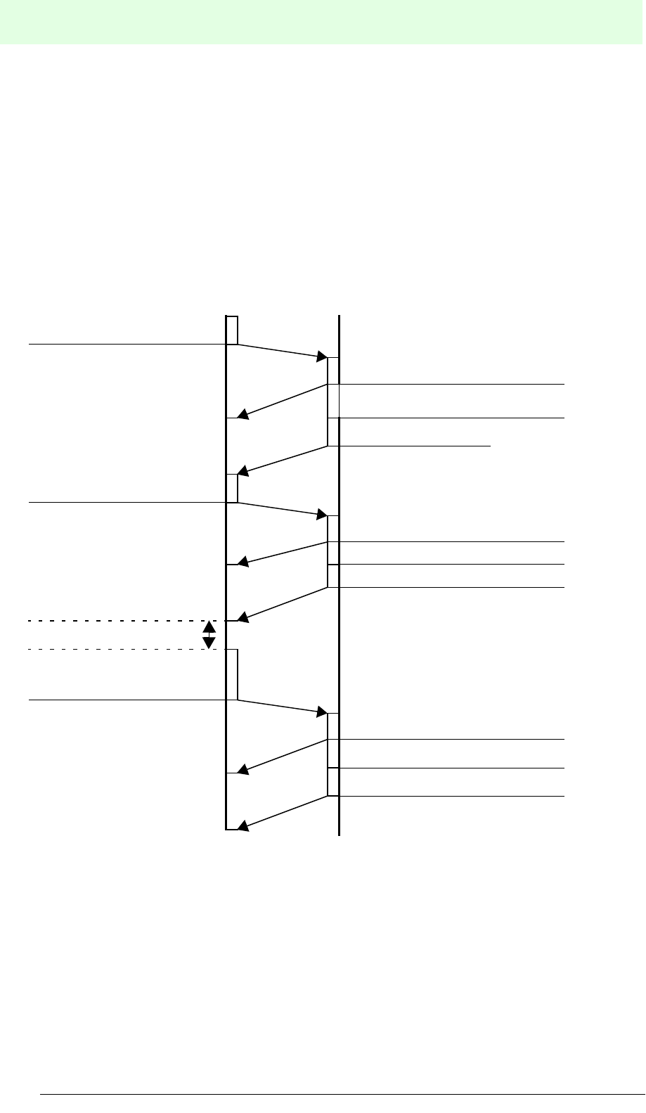
IDENT-M System V
Transmission Procedure
Date of issue 03.05.2001
98
Subject to reasonable modifications due to technical advances. Copyright Pepperl+Fuchs, Printed in Germany
Pepperl+Fuchs Group • Tel.: Germany (06 21) 7 76-0 • USA (330) 4 25 35 55 • Singapore 7 79 90 91 • Internet http://www.pepperl-fuchs.com
8.2 Output Instructions
The MVI-D2-2HRX has four outputs, from 0 to 3.
ON/OFF-specifications of the outputs
• Turn the outputs ON or OFF with the host controller's “output instruction”.
• ON and OFF time is freely selectable.
8.2.1 Example for the Use of Output 0 for a Normal End
Transmission sequence (occasional execution system + auto response system).
Set output 0 to ON
Send command
Send acknowledgement
Send end message
MVI-D2-2HRXHost controller
Execute a function like a transfer to
data carriers
Send output instruction
(command to set
output 0 to ON)
Send acknowledgement
Send end message
Send output instruction
(command to set
output 0 to OFF)
Elapse of the time interval
Set output 0 to OFF
Send acknowledgement
Send end message
ß
ßß
ß Normal end
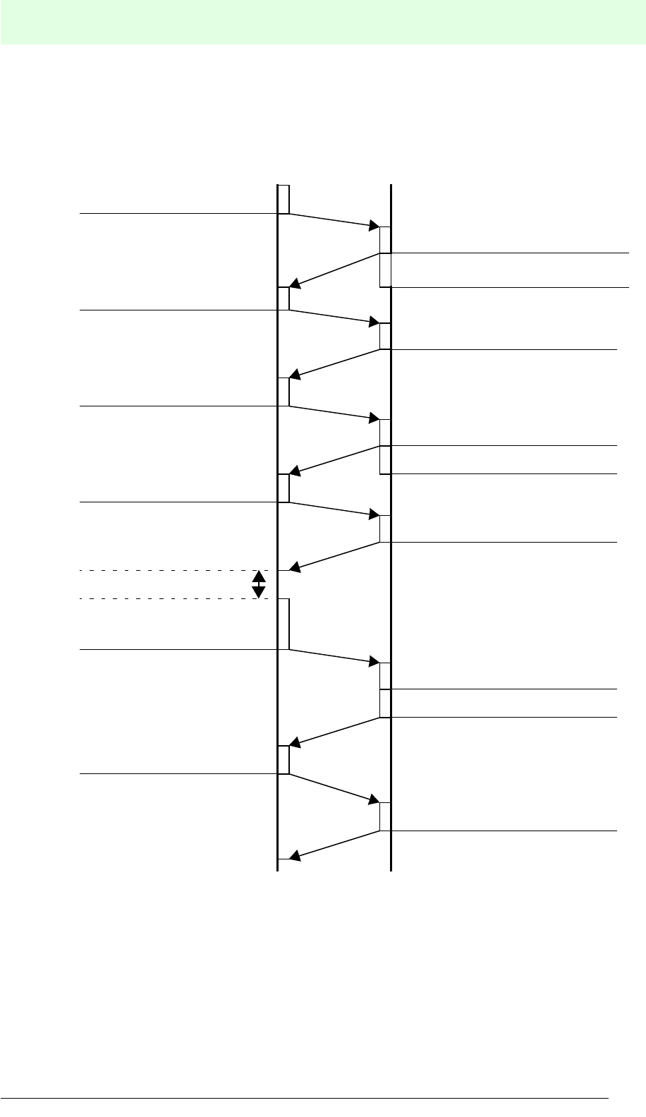
IDENT-M System V
Transmission Procedure
Date of issue 03.05.2001
99
Subject to reasonable modifications due to technical advances. Copyright Pepperl+Fuchs, Printed in Germany
Pepperl+Fuchs Group • Tel.: Germany (06 21) 7 76-0 • USA (330) 4 25 35 55 • Singapore 7 79 90 91 • Internet http://www.pepperl-fuchs.com
Transmission Sequence
(Occasional execution system + response request system)
Set output 0 to ON
Send command
Send acknowledgement
Send end message
MVI-D2-2HRXHost controller
Execute a function like a transfer to
data carriers
Send output instruction
(command to set
output 0 to ON)
Send acknowledgement
Send end message
Send output instruction
(command to set
output 0 to OFF)
Elapse of the time interval
Set output 0 to OFF
Send acknowledgement
Send end message
Send acknowledgement
Send acknowledgement
Send acknowledgement
ß
ßß
ß Normal end
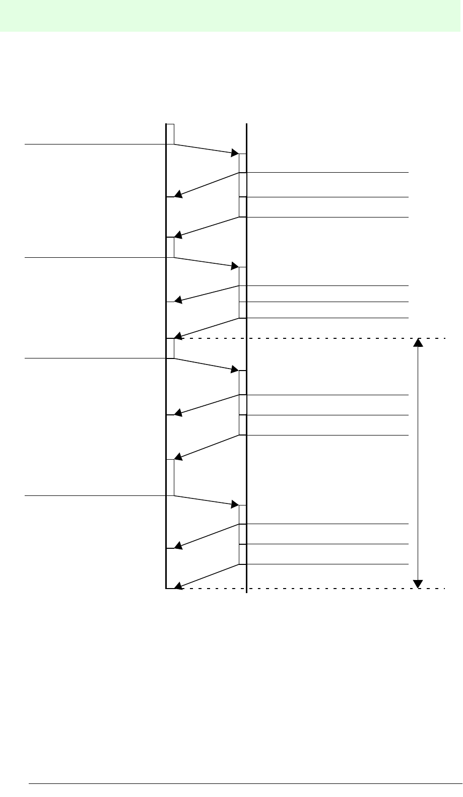
IDENT-M System V
Transmission Procedure
Date of issue 03.05.2001
100
Subject to reasonable modifications due to technical advances. Copyright Pepperl+Fuchs, Printed in Germany
Pepperl+Fuchs Group • Tel.: Germany (06 21) 7 76-0 • USA (330) 4 25 35 55 • Singapore 7 79 90 91 • Internet http://www.pepperl-fuchs.com
8.2.2 Example for the Use of Output 1 as an Error Output
Transmission sequence (occasional execution system + auto response system).
Set output 1 to ON
Send command
Send acknowledgement
Send error signal
MVI-D2-2HRXHost controller
Execute a function like a transfer to
data carriers
Send output instruction
(command to set
output 1 to ON)
Send acknowledgement
Send end message
Send output instruction
(command to set
output 1 to OFF)
Set output 1 to OFF
Send acknowledgement
Send end message
Send reset command
Reset error condition
Send acknowledgement
Send end message
Reset
the error
ß
ßß
ß Error
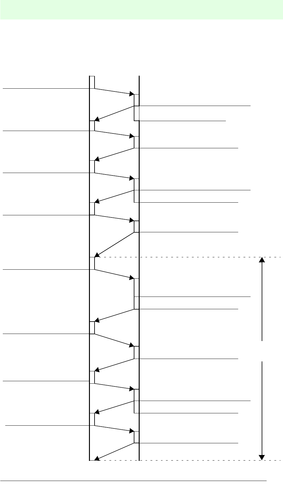
IDENT-M System V
Transmission Procedure
Date of issue 03.05.2001
101
Subject to reasonable modifications due to technical advances. Copyright Pepperl+Fuchs, Printed in Germany
Pepperl+Fuchs Group • Tel.: Germany (06 21) 7 76-0 • USA (330) 4 25 35 55 • Singapore 7 79 90 91 • Internet http://www.pepperl-fuchs.com
Transmission Sequence
(Occasional execution system + response request system)
Set output 1 to ON
Send command
Send acknowledgement
Send end message
MVI-D2-2HRXHost controller
Execute a function like a
transfer to data carriers
Send output instruction
(command to set
output 0 to ON)
Send acknowledgement
Send end message
Send reset command
Reset error condition
Send acknowledgement
Send end message
Send acknowledgement
Send acknowledgement
Send acknowledgement
Send output instruction
(command to set
output 0 to OFF)
Set output 1 to OFF
Send reception command
Send acknowledgement
Send end message
Reset the
error
ß
ßß
ß Normal end

IDENT-M System V
Transmission Procedure
Date of issue 03.05.2001
102
Subject to reasonable modifications due to technical advances. Copyright Pepperl+Fuchs, Printed in Germany
Pepperl+Fuchs Group • Tel.: Germany (06 21) 7 76-0 • USA (330) 4 25 35 55 • Singapore 7 79 90 91 • Internet http://www.pepperl-fuchs.com
Memory of the Data Carrier
Addresses 1D80h to 7FFFh and 807Eh and after are blocked for trans-
mission.
Designation of
memory area
Address Number
of bytes Initial valueh
Write
Cleara
a. “Reading”, “writing” or “clearing” data values by the user program.
Readb
b. The copy command, in this case, is the same as “read” + “write”.
Hex. h Dec. dOctal 8
(1) Data area
0
...
1D7F
0
...
7551
0
...
16577
7552
00
available
available
System area
(2) Free area
8000
...
803F
32768
...
32831
100000
...
100077
64
(3) ID code
8040
...
8043
32832
...
32835
100100
...
100103
4
(4) Data carrier
prod. date
Month 8044 32836 100104 2 Set at
production
not available
Year 8045 32837 100105
(5) Number of transmission
operations
8046
...
8049
32838
...
32841
100106
...
100111
4
00
(6) Operation time 1
(LED does not light)
804A
...
804D
32842
...
32845
100112
...
100115
4
(7) Operation time 2 (LED
lights)
804E
...
8051
32846
...
32849
100116
...
100121
4
(8) Reception off-time 8052
8053
32850
32851
100122
100123 2
available
(9) Setting the time when
the LED lights. 8054 32852 100124 1
System area protection 8055 32853 100125 1
(10) Write-protected data area
#1 Start address 8056,7 32854,5 100126,7
40
Number bytes 8058,9 32856,7 100130,1
#2 Start address 805A,B 32858,9 100132,3
Number bytes 805C,D 32860,1 100134,5
#3 Start address 805E,F 32862,3 100136,7
Number bytes 8060,1 32864,5 100140,1
#4 Start address 8062,3 32866,7 100142,3
Number bytes 8064,5 32868,9 100144,5
#5 Start address 8066,7 32870,1 100146,7
Number bytes 8068,9 32872,3 100150,1
#6 Start address 806A,B 32874,5 100152,3
Number bytes 806C,D 32876,7 100154,5
#7 Start address 806E,F 32878,9 100156,7
Number bytes 8070,1 32880,1 100160,1
#8 Start address 8072,3 32882,3 100162,3
Number bytes 8074,5 32884,5 100164,5
#9 Start address 8076,7 32886,7 100166,7
Number bytes 8078,9 32888,9 100170,1
#A Start address 807A,B 32890,1 100172,3
Number bytes 807C,D 32892,3 100174,5

IDENT-M System V
Transmission Procedure
Date of issue 03.05.2001
103
Subject to reasonable modifications due to technical advances. Copyright Pepperl+Fuchs, Printed in Germany
Pepperl+Fuchs Group • Tel.: Germany (06 21) 7 76-0 • USA (330) 4 25 35 55 • Singapore 7 79 90 91 • Internet http://www.pepperl-fuchs.com
Memory Area Designations and their Functions and Contents:
1. Data area and
2. free area:
Data area and free area store arbitrary data
3. ID code
Available values: 4.294.967.295
Hexadecimal: FFFFFFFh
Decimal: 1 ... 4294967295d
Octal: 1 ... 377777777778
Example: ID code 1234568
4. Production date of the data carrier
The production month is encoded in BCD code 01 to 12. The production year is
encoded in BCE code 00 to 99 without the first two digits of the year.
Production month of data carrier
Examples:
Produced in September Produced in December
Production year of data carrier
Example:
Produced in 1993
5. Number of transmission procedure
Each command, that causes a communication between the read/write head and
the data carrier, has the effect that the counter increments by one.
0 to 4.294.967.295d (maximum number of communication procedures)
Memory address 8043h8042h8041h8040h
00000000000000001010011100101110
ID code 0 0 0 0 0 123456
Memory address 8044hMemory address 8044h
00001001 00010010
Month 09 Month 12
Memory address 8045h
10010011
Year 93

IDENT-M System V
Transmission Procedure
Date of issue 03.05.2001
104
Subject to reasonable modifications due to technical advances. Copyright Pepperl+Fuchs, Printed in Germany
Pepperl+Fuchs Group • Tel.: Germany (06 21) 7 76-0 • USA (330) 4 25 35 55 • Singapore 7 79 90 91 • Internet http://www.pepperl-fuchs.com
6. Accumulated operation time 1 (LED does not light)
When the data carrier communicates with a read/write head, the data carrier
changes into the active operating status. This value is the total of the active
operation time. The value is between 1 and 4.294.967.295d ms.
7. Accumulated operation time 2 (LED lights)
This value equals the total period of time, in which the LED of the data carrier's
activity light is illuminated. The value is between 1 and 4.294.967.295d ms.
8. Reception off-time
After communicaton of the data carrier with a read/write head, the data carrier
does not accept further commands for the time that has been set. Set to 0 to
65535 seconds.
9. Set time, during which the LED lights
Set the lighting time of the data carrier's LED between 0.2 and 25.5 seconds. The
set values 2 to 255d are equal to 0.2 to 25.5 seconds. Set the command for the
LED to light in the memory address 9002h (1100028) of MVI-D2-2HRX.
10. Write protection
This function is to protect data in the data carrier from being deleted inadvertently.
Set write-protected area (memory address: 8055h and after).

IDENT-M System V
Transmission Procedure
Date of issue 03.05.2001
105
Subject to reasonable modifications due to technical advances. Copyright Pepperl+Fuchs, Printed in Germany
Pepperl+Fuchs Group • Tel.: Germany (06 21) 7 76-0 • USA (330) 4 25 35 55 • Singapore 7 79 90 91 • Internet http://www.pepperl-fuchs.com
When the write-protected area receives commands such as “write”, “clear” or “copy”
the MVI-D2-2HRX returns the following information in the error signal:
• Protection error (error code 18h).
• Start address of the write-protected area.
Item Contents
Setting method
Data area
Set start address and number of bytes for the write protection in the “write-
protected area”.
Example:
Set 1023 (17778) bytes from area address123458 to 143438 on protection 1.
System area
Set contents of memory addresses 8055h (1001258) to FFh.
Setting range
Data area
MVC-60-64K: 0000...1D7Fh (000000...0165778)
System area
Whole area (except write protection adjustment range).
Setting positions
Data area
Max. 10 positions (save areas 1 to Ah).
System area
1 position (whole area).
Reset
the setting Set the respective position of the “write-protected area” to 0.
Memory address 8057h8056h
0001010011100101
Start address 0 12345
Memory address 8059h8058h
0000001111111111
Number of bytes001777
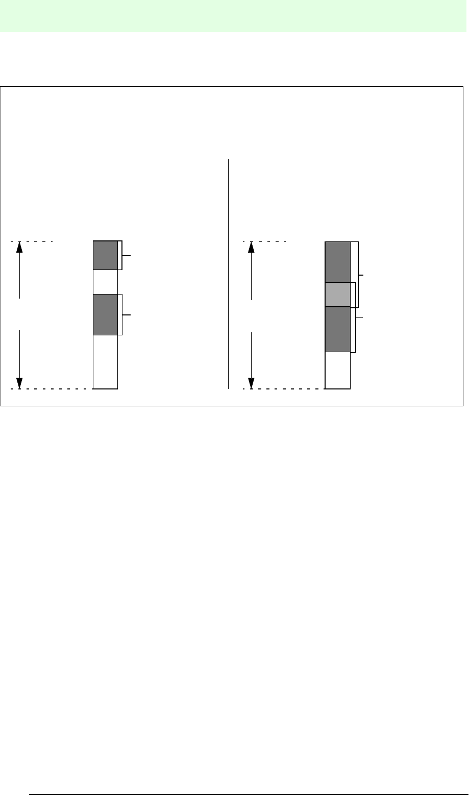
IDENT-M System V
Transmission Procedure
Date of issue 03.05.2001
106
Subject to reasonable modifications due to technical advances. Copyright Pepperl+Fuchs, Printed in Germany
Pepperl+Fuchs Group • Tel.: Germany (06 21) 7 76-0 • USA (330) 4 25 35 55 • Singapore 7 79 90 91 • Internet http://www.pepperl-fuchs.com
Note:
• Save areas 1 to 9 and Ah do not have to be set in the order of addresses in the
data area (as shown in example 1).
• The write-protected area can be set by overlapping with other write-protection
settings (as shown in example 2).
00000
02100
04000
07777
Address8
Example 1:
Save area 2 has a smaller
address as save area 1
Example 2:
The setting range of the write
protection is 000008 to 117778
Setting range of
save area 2
Setting range of
save area 1
00000
02377
06000
11777
Address8
Setting range of
save area 1
Setting range of
save area 2
Data
area
Data
area

IDENT-M System V
Transmission Procedure
Date of issue 03.05.2001
107
Subject to reasonable modifications due to technical advances. Copyright Pepperl+Fuchs, Printed in Germany
Pepperl+Fuchs Group • Tel.: Germany (06 21) 7 76-0 • USA (330) 4 25 35 55 • Singapore 7 79 90 91 • Internet http://www.pepperl-fuchs.com
8.3 Memory of the Control Interface Unit
The MVI-D2-2HRX has both a data carrier buffer (data area and system area) and a
system memory (data carrier transmission area and special area for the MVI-D2-
2HRX).
• The contents of the data carrier buffer is the same as that of the data carrier
memory.
• In order to set or change data, use the following commands: read MVI-D2-2HRX
(15h), write MVI-D2-2HRX (25h), clear MVI-D2-2HRX (35h), initialise MVI-D2-
2HRX (36h) and clear the protocol area (37h).
Memory area designation Address
(hex.)
Number of
bytes
Read/write head 0
Data carrier
buffer
Data area
0000
...
1D7F
7552
System area
8000
...
807D
126
System memory
(Data carrier transmission range)
9000
...
9D81
3458
Read/write head 1
Data carrier
buffer
Data area
0000
...
1D7F
7552
System area
8000
...
807D
126
System memory
(Data carrier transmission range)
9000
...
9D81
3458
System memory (specifically for MVI-D2-2HRX)
A000
...
A00B
12

IDENT-M System V
Transmission Procedure
Date of issue 03.05.2001
108
Subject to reasonable modifications due to technical advances. Copyright Pepperl+Fuchs, Printed in Germany
Pepperl+Fuchs Group • Tel.: Germany (06 21) 7 76-0 • USA (330) 4 25 35 55 • Singapore 7 79 90 91 • Internet http://www.pepperl-fuchs.com
System Memory (Data Carrier Transmission Range)
Memory area designation Address
(hex h)
Number
of bytes
Initial
value
(hex.)
(1) Recognition time 9000 1 00
(2) LED operation
monitor
Data carrier LED ON 9002 1
Adjusting time for LED 9003 1 05
(3) Register of
transmission
function
Function at the trigger input is
ON 9010 1
00
Transmission function
contents
9011
...
909C
140
(4) Time protocol of
the transmission
(actual result)
Number of operations/
commands
90A0
...
90A3
4
00
Current value
90A4
...
90A7
4
Mean value
90A8
...
90AB
4
Maximum value
90AC
...
90AF
4
Minimum value
90B0
...
90B3
4
(5) Number of repeats
protocol (actual
result)
Number of functions
90C0
...
90C3
4
Current value 90C4,5 2
Mean value 90C6,7 2
Maximum value 90C8,9 2
Minimum value 90CA,B 2
(6) Error protocol
Register protocol pointer 9100,1 2 9102
Contents of error protocol
9102
...
9D81
3200 00
(7) Display of the time
Second A000
7Time
Minute A001
Hour A002
Day A003
Month A004
Year A005
Weekday A006
(8) Instruction mode A008 1
(9) Response time A009 1
(10) Response return system A00A 1
(11) Read/write head scan last station A00B 1

IDENT-M System V
Transmission Procedure
Date of issue 03.05.2001
109
Subject to reasonable modifications due to technical advances. Copyright Pepperl+Fuchs, Printed in Germany
Pepperl+Fuchs Group • Tel.: Germany (06 21) 7 76-0 • USA (330) 4 25 35 55 • Singapore 7 79 90 91 • Internet http://www.pepperl-fuchs.com
The following addresses are reserved and blocked for transmission:
9001h, 9004h ... 900Fh, 909Dh ... 909Fh, 90B4 ... 90BFh, 90C8h ... 90FFh, A007h
1. Recognition time see page 136.
2. Operating supervision by LEDs
The start and the end of a transmission function can be checked by LEDs placed
on the read/write heads and the data carriers.
Read/write head
LED: TX
Flashes in the case of a transmission
between the read/write head and the data
carrier.
LED: OK
Lights at the end of a transmission
between a read/write head and the data
carrier.
Setting Set Area Setting contents
LED: OK
Lighting time T1
Memory address of MVI-
D2-2HRX 9003h
0 sec ... 25.5 sec.
Initial value 0.5 sec.
e. g. 255d as 25.5 sec.
LED: OK
LED: TX
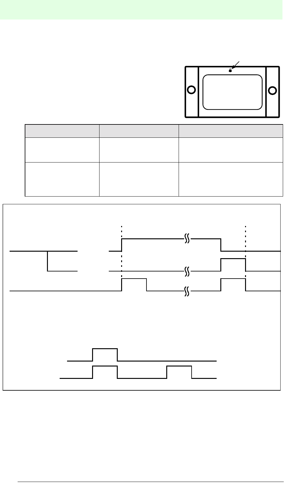
IDENT-M System V
Transmission Procedure
Date of issue 03.05.2001
110
Subject to reasonable modifications due to technical advances. Copyright Pepperl+Fuchs, Printed in Germany
Pepperl+Fuchs Group • Tel.: Germany (06 21) 7 76-0 • USA (330) 4 25 35 55 • Singapore 7 79 90 91 • Internet http://www.pepperl-fuchs.com
Data carrier
LED - Lights at the start and at the end of a
transmission.
Setting Set Area Setting contents
Lighting time T2 Memory address of data
carrier: 8054h
0.2 sec ... 25.2 sec.
(Initial value 0 sec.)
e.g. 255d as 25.5 sec.
Lighting instructions Memory address of MVI-
D2-2HRX: 9002h
00h: does not light
01h: lights at the start of
transmission
FFh: lights at the end of transmission
LED
LED lighting time chart
T1
T1 T1
T2
Read/write head LED: TX
LED: OK
T2
T1
Data carrier LED
End of
trans-
mission
Start of
transmission
LED lights at the
start of
transmission
LED lights at the
end of
transmission
Without repeat
With repeat
The LED lights when transmission is repeated: OK on the read/write head lights twice.

IDENT-M System V
Transmission Procedure
Date of issue 03.05.2001
111
Subject to reasonable modifications due to technical advances. Copyright Pepperl+Fuchs, Printed in Germany
Pepperl+Fuchs Group • Tel.: Germany (06 21) 7 76-0 • USA (330) 4 25 35 55 • Singapore 7 79 90 91 • Internet http://www.pepperl-fuchs.com
3. Storage of commands
This storage and execution is only available when the command register system
is used as communication startup system (set memory address A008h to 2).
• Storage
Determine the contents of the transmission function (transmission code,
attributes etc.) and store it as command.
Determine the memory area by inserting storage numbers 1 to 8 into the field
“registration” of the command.
• Execution method
When the MVI-D2-2HRX receives the command (command code 75h) from the
host controller, the storage number, which is to be executed when the trigger input
is activated, is stored in the MVI-D2-2HRX system memory (address 9010h).
Each time the trigger input is activated, the MVI-D2-2HRX executes the
registered command, which is allocated by the host controller by means of the the
75h command.
While the MVI-D2-2HRX trigger input is active, the communication function,
allocated by command 75h, is executed.
•Halt
The instruction execution can be stopped by sending the command “halt”
(command code 74h). In this case, the MVI-D2-2HRX does not start the
transmission even if the trigger input is active (ON) (address 9010h = 0).
• Other
The MVI-D2-2HRX indicates an error when you try to start the function by means
of the start command with other than the command register system.
Store the write data to the data carrier buffer of the MVI-D2-2HRX.

IDENT-M System V
Transmission Procedure
Date of issue 03.05.2001
112
Subject to reasonable modifications due to technical advances. Copyright Pepperl+Fuchs, Printed in Germany
Pepperl+Fuchs Group • Tel.: Germany (06 21) 7 76-0 • USA (330) 4 25 35 55 • Singapore 7 79 90 91 • Internet http://www.pepperl-fuchs.com
Function Memory Table
Memory area Number
of bytes Description Address
(hex.)
Number
of bytes
Transmission function
with a trigger signal 1
0: Block the function
1 to 8: Registration number
(unblock the function)
9010 1
Reserved area 1 9011 1
Transmission function contents
Memory
number 1 16
Tansmission code 9012 1
Protection method 9013 1
Attribute 9014 1
Start address 9015 2
Number of bytes 9017 2
Start address of transmission
target area 9019 2
Data Code (DCD) 901B 1
ID code 901C 4
Clear data 9020 1
Reserved area 9021 1
···
···
···
···
···
Memory
number 8 16
Tansmission code 9082 1
Protection method 9083 1
Attribute 9084 1
Start address 9085 2
Number of bytes 9087 2
Start address of transmission
target area 9089 2
Data Code (DCD) 908B 1
ID code 908C 4
Clear data 9090 1
Reserved data 9091 1
Reserved area 14 9092

IDENT-M System V
Transmission Procedure
Date of issue 03.05.2001
113
Subject to reasonable modifications due to technical advances. Copyright Pepperl+Fuchs, Printed in Germany
Pepperl+Fuchs Group • Tel.: Germany (06 21) 7 76-0 • USA (330) 4 25 35 55 • Singapore 7 79 90 91 • Internet http://www.pepperl-fuchs.com
4. Time protocol of the transmission
The MVI-D2-2HRX stores the processing time from the start to the end of the
transmission between the read/write head and the data carrier onto its memory
addresses 90A0h to 90B3h. These processing times are subdivided into current value,
mean value, maximum and minimum value. The “clear protocol” function from the
host controller can initialise the maximum, minimum and mean value. It is not possible
to write with any other function.
5. Number of communication attempts protocol
The MVI-D2-2HRX stores the number of repeats from the start to the end of
transmission between the read/write head and the data carrier onto its memory
addresses 90C0h to 90CBh. The “clear protocol” function from the host controller
can initialise the maximum, minimum and mean value. It is not possible to write
with any other function.
Memory area
Contents
Before
measuring
transmission
time
After measuring
transmission time Memory data
Transmis-
sion time
(current
result)
Number of
functions N' N = N' + 1 0 ... 4.294.967.295d
times
Current
value T1' T1
0 ... 4.294.967.295d ms
Mean value T2'
Maximum
value T3' T3' ³ T1: max. value T3'
T3' < T1: max. value T1
Minimum
value T4' T4' £ T1: min. value T4'
T4' > T1: min. value T1
Memory area
Contents
Before
measuring
transmission
time
After measuring
transmission time Memory data
Transmis-
sion time
(current
result)
Number of
operations N' N = N' + 1 0 ... 4.294.967.295d
Current
value R1' R1
0 ... 255d
Mean value R2'
Maximum
value R3' R3' ³ R1: max. value R3'
R3' < R1: max. value R1
Minimum
value R4' R4' £ R1: min. value R4'
R4' > R1: min. value R1
T
2
=
(T
2
’*N’)+T
1
N’+1
R2 =
(R2’*N’)+R1
N’+1

IDENT-M System V
Transmission Procedure
Date of issue 03.05.2001
114
Subject to reasonable modifications due to technical advances. Copyright Pepperl+Fuchs, Printed in Germany
Pepperl+Fuchs Group • Tel.: Germany (06 21) 7 76-0 • USA (330) 4 25 35 55 • Singapore 7 79 90 91 • Internet http://www.pepperl-fuchs.com
6. Setting the current time
Set the time of the clock integrated into the MVI-D2-2HRX to memory address
A000h to A006h of MVI-D2-2HRX.
7. Error protocol
When the result of a command is faulty the MVI-D2-2HRX stores the error
protocol to its memory addresses 9100h to 9D81h.
• The MVI-D2-2HRX stores the error contents onto the address which is set 32
bytes before the start address of the protocol in the “storage protocol pointer”
(address: 9100h, 9101h).
• After the storage of the error contents, the start address of the protocol is set 32
bytes ahead of the “storage protocol pointer”.
• The initial value of the “storage protocol pointer” is 9102h.
• The error protocol area can be reset by means of the host controller's “clear
protocol” function.
• When the protocol data reach 100, the data is overwritten by protocol data 1.
Memory area designation Contents
Display of
current time
Second 00 ... 59 (BCD code)
Minute 00 ... 59 (BCD code)
Hour 00 ... 23 (BCD code)
Day 01 ... 31 (BCD code)
Month 01 ... 12 (BCD code)
Year 00 ... 99 (BCD code)
Weekday Sun. Mon. Tue. Wed. Thu. Fri. Sat.
00h01h02h03h04h05h06h

IDENT-M System V
Transmission Procedure
Date of issue 03.05.2001
115
Subject to reasonable modifications due to technical advances. Copyright Pepperl+Fuchs, Printed in Germany
Pepperl+Fuchs Group • Tel.: Germany (06 21) 7 76-0 • USA (330) 4 25 35 55 • Singapore 7 79 90 91 • Internet http://www.pepperl-fuchs.com
Item Number
of bytes Detailed item (contents) Start address
hex. h
Number
of bytes
Storage
protocol
pointer
2Start address of the protocol data of the last error
storage 9100 2
Protocol data 1
32
Storage time
Second 9102 6
Minute 9103
Hour 9104
Day 9105
Month 9106
Year 9107
Error code 9108 1
Error information 9109 6
Execution
contents
Command 910F 1
Attribute 9110 1
ID code 9111 4
Start address 9115 2
Number of bytes 9117 2
Target area start address 9119 2
Data carrier error 911B 1
Asynchronous error 911C 1
Time-out error during the last data reception 911D 1
Incorrect number of bytes 911E 1
Check sum error 911F 1
Grammatical error 9120 1
Reserved area 9121 1
...
...
...
...
...
Protocol data 100
32
Storage time
Second 9D62
6
Minute 9D63
Hour 9D64
Day 9D65
Month 9D66
Year 9D67
Error code 9D68 1
Error information 9D69 6

IDENT-M System V
Transmission Procedure
Date of issue 03.05.2001
116
Subject to reasonable modifications due to technical advances. Copyright Pepperl+Fuchs, Printed in Germany
Pepperl+Fuchs Group • Tel.: Germany (06 21) 7 76-0 • USA (330) 4 25 35 55 • Singapore 7 79 90 91 • Internet http://www.pepperl-fuchs.com
8. Communication startup system
The communication startup system is determined by the contents of the MVI-D2-
2HRX memory address A008h.
In order to change the communication startup system, the content of the storage
cell A008h should be overwritten and then the supply voltage of the control
interface unit has to be switched OFF and then ON again.
9. Response time (RI)
This function is used when the MVI-D2-2HRX returns another message
immediately after instruction execution, while the host controller is still processing
previous data.
10. Contents (between host controller and each MVI-D2-2HRX)
[In the case of the auto response systems]
This function is available, in order to insert a time interval in between the
command and the “sending of acknowledgement”.
Protocol data 100
32
Execution
contents
Command 9D6F 1
Attribute 9D70 1
ID code 9D71 4
Start address 9D75 2
Number of bytes 9D77 2
Target area start address 9D79 2
No data carrier error 9D7B 7
Asynchronous error 9D7C 1
Time-out error during the last reception of data 9D7D 1
Byte counter error 9D7E 1
Check sum error 9D7F 1
Grammatical error 9D80 1
Reserved area 9D81 1
Area name of memory Address Setting contents Initial value
Communication
startup system
A008h
00h= Occasional
execution system
00h
(Occasional execution
system)
01h= Command stay
system
02h= Command register
system
03h= Read/write head
scan system
Item Number
of bytes Detailed item (contents) Start address
hex. h
Number
of bytes

IDENT-M System V
Transmission Procedure
Date of issue 03.05.2001
117
Subject to reasonable modifications due to technical advances. Copyright Pepperl+Fuchs, Printed in Germany
Pepperl+Fuchs Group • Tel.: Germany (06 21) 7 76-0 • USA (330) 4 25 35 55 • Singapore 7 79 90 91 • Internet http://www.pepperl-fuchs.com
Example: Occasional Execution + Auto Response System
• When the processing time between the read/write head and the data carrier is
longer than the RI setting value, an end message is sent at the end of the
processing between the read/write head and the data carrier.
• When the processing time between the read/write head and the data carrier is
shorter than the RI setting value after sending the acknowledgement, the MVI-D2-
2HRX delays transmission of the end message with the RI setting value.
[In the case of the response request systems]
This function is available, in order to insert an interval between receiving the
command and sending the acknowledgement as well as between receiving the
acknowledgement request and sending the end message.
Execution of a function such as
transmission to a data carrier
Send command
Send end message
Control interface unitHost controller
Response
time: RI
Send acknowledgement
*Period of time until end message is sent
*
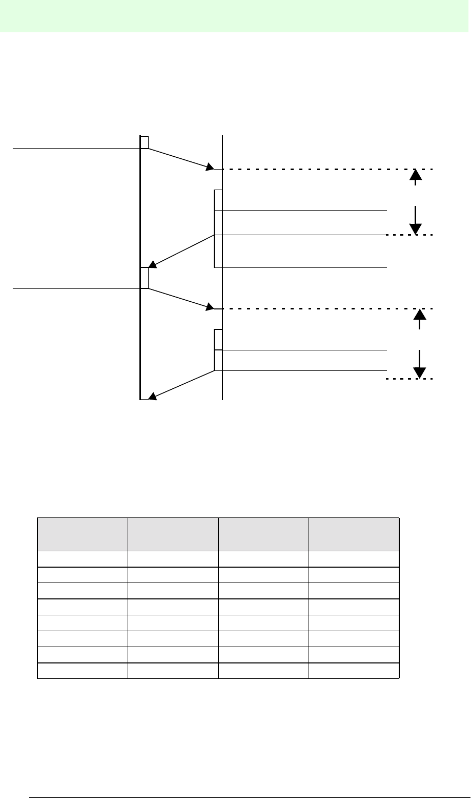
IDENT-M System V
Transmission Procedure
Date of issue 03.05.2001
118
Subject to reasonable modifications due to technical advances. Copyright Pepperl+Fuchs, Printed in Germany
Pepperl+Fuchs Group • Tel.: Germany (06 21) 7 76-0 • USA (330) 4 25 35 55 • Singapore 7 79 90 91 • Internet http://www.pepperl-fuchs.com
Example: Occasional Execution + Response Request System
11. Setting values
The RI response time can be set to up to 600 ms in the system memory (address
A009h) of the MVI-D2-2HRX.
.
Setting value
(hex.)
Response time
RI (ms)
Setting value
(hex.)
Response time
RI (ms)
00880
110990
2 20 A 100
3 30 B 200
4 40 C 300
5 50 D 400
6 60 E 500
770F600
Execution of a function such as
transmission to a data carrier
Send command
Send end message
Control interface unitHost controller
Response
time: RI
Send acknowledgement
Response
time:
Checking station number
Checking station number
Send acknowledgement

IDENT-M System V
Transmission Procedure
Date of issue 03.05.2001
119
Subject to reasonable modifications due to technical advances. Copyright Pepperl+Fuchs, Printed in Germany
Pepperl+Fuchs Group • Tel.: Germany (06 21) 7 76-0 • USA (330) 4 25 35 55 • Singapore 7 79 90 91 • Internet http://www.pepperl-fuchs.com

IDENT-M System V
Commands
Date of issue 03.05.2001
120
Subject to reasonable modifications due to technical advances. Copyright Pepperl+Fuchs, Printed in Germany
Pepperl+Fuchs Group • Tel.: Germany (06 21) 7 76-0 • USA (330) 4 25 35 55 • Singapore 7 79 90 91 • Internet http://www.pepperl-fuchs.com
9 Commands
9.1 Common Code
ASCII code is used for commands and messages.
Data (ASCII) Code (hex.) Contents
STA 0 to F Station number 1
(1) Command: Station number to receive data.
(2) Message: Station number of the emitting station.
ANT 0,1, *
Read/write head number *( Used for allocating the access
functions of the read/write head scan system and the MVI-
D2-2HRX.)
SC(H), SC(L) Two digits
(00 to FF) Checksum
EK(H), EK(L) Two digits
(00 to FF)
Position of occurred error
00: Between host controller and MVI-D2-2HRX
10: Between MVI-D2-2HRX and read/write head 0
11: Between MVI-D2-2HRX and read/write head a
a. Set “0” in order to select read/write head scan function.
EC(H), EC(L) Two digits
(00 to FF) Error code
Error
information Twelve digits Information on error contents such as start address of
block check error
:3A
Header (indicates the head of the command and the
response).
? 3F Indicates the command
$ 24 Indicates acknowledgement (normal operation).
# 23 Indicates end message (normal operation).
% 25 Indicates error message.
!21
Indicates command for communication of a specific control
interface unit with the read/write head scan system
CR 0D End code (indicates end of command or message).b
b. Some languages used by the host controller automatically add “CR”. In this case, the
“CR” command is not required.
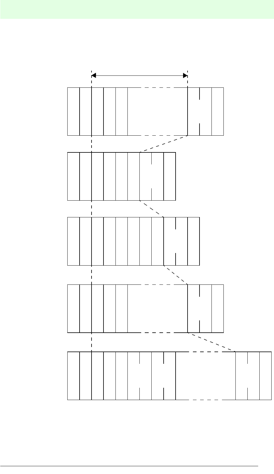
IDENT-M System V
Commands
Date of issue 03.05.2001
121
Subject to reasonable modifications due to technical advances. Copyright Pepperl+Fuchs, Printed in Germany
Pepperl+Fuchs Group • Tel.: Germany (06 21) 7 76-0 • USA (330) 4 25 35 55 • Singapore 7 79 90 91 • Internet http://www.pepperl-fuchs.com
9.2 Instruction Format
9.2.1 Standard Format
E
(L)
K
E
(H)
K
E
(L)
C
E
(H)
C
?
S
(H)
C
S
(L)
C
$
R
C
: :
S
A
T
A
T
N
Command
contents
?
S
(H)
C
S
(L)
CR
C
: :
S
A
T
A
T
N
$?
S
(H)
C
S
(L)
CR
C
: :
S
A
T
A
T
N7 1
%
S
(H)
C
S
(L)
CR
C
: :
S
A
T
A
T
N
Command
contents
#
S
(H)
C
S
(L)
CR
C
: :
S
A
T
A
T
N
Command
contents
Checksum range
Acknowledgement
Command
Acknowledgement
request 1
End message 2
Error message

IDENT-M System V
Commands
Date of issue 03.05.2001
122
Subject to reasonable modifications due to technical advances. Copyright Pepperl+Fuchs, Printed in Germany
Pepperl+Fuchs Group • Tel.: Germany (06 21) 7 76-0 • USA (330) 4 25 35 55 • Singapore 7 79 90 91 • Internet http://www.pepperl-fuchs.com
1 When the MVI-D2-2HRX completes an operation, while receiving an acknowledge-
ment request, it sends the following end message to the host controller.
When the MVI-D2-2HRX receives an acknowledgement request, when it has already
finished the operation, it sends the normal end message to the host controller.
2 As soon as the command register system has stored an operation in the MVI-D2-
2HRX, the following end message is sent to the host controller.
9.2.2 Setting the Read/Write Station Number
Set read/write head number (“0” or “1”) in order to execute the command.
• The number of the read/write head is determined by the terminal number of the
read/write head at the MVI-D2-2HRX.
• When the read/write head scan is used, the character “ *” is inserted
in the command.
• In order to copy data (with check) between the read/write heads, the read/write
head number of the data source has to be set.
• When the special area of the MVI-D2-2HRX system memory is accessed, the
host controller accesses the same address, disregarding whether the command
is set to 0 or 1.
S
A
T
A
T
N
S
(H)
C
S
(L)
CR
C
1#
: : 7
S
A
T
A
T
N
S
(H)
C
S
(L)
CR
C
#
: : 7
Registration
Command
code

IDENT-M System V
Commands
Date of issue 03.05.2001
123
Subject to reasonable modifications due to technical advances. Copyright Pepperl+Fuchs, Printed in Germany
Pepperl+Fuchs Group • Tel.: Germany (06 21) 7 76-0 • USA (330) 4 25 35 55 • Singapore 7 79 90 91 • Internet http://www.pepperl-fuchs.com
9.2.3 Check Sum
In order to improve the reliability of the data transmission, the MVI-D2-2HRX can
ascertain errors both with checksum tests and parity checks (Checksum range see
page 121).
Test procedure
1. All data of the station number is added up to the end of the command contents or
to the end of the messages, and the lowest byte of this amount is converted to
ASCII.
2. The data is correct when the sum across the checksum range and the checksum
itself is 0. When the overall result is a number not equal to 0, this is treated as an
error.
Data creation during the checksum procedure
1. Adds up the ASCII values of the station numbers up to the command contents or
to the end of the message contents (just before the checksum code).
2. Constitutes the two's complement from this sum.
• Two's complement: All data bits are inverted (0 to 1, 1 to 0) and 1 is added.
Ex.: Two's complement of 4Eh is B2h.
3. Divide the data to the first 4 bits and the second 4 bits and convert them to ASCII
code.
When the calculation of the checksum is too expensive, the checksum can be
replaced by “@@”.
4Eh à 01001110
¯invert
10110001
¯add 1
10110010 à B2h
:?
S
A
T
A
T
N
S
(H)
C
S
(L)
C
:R
C
Command
contents
Checksum range
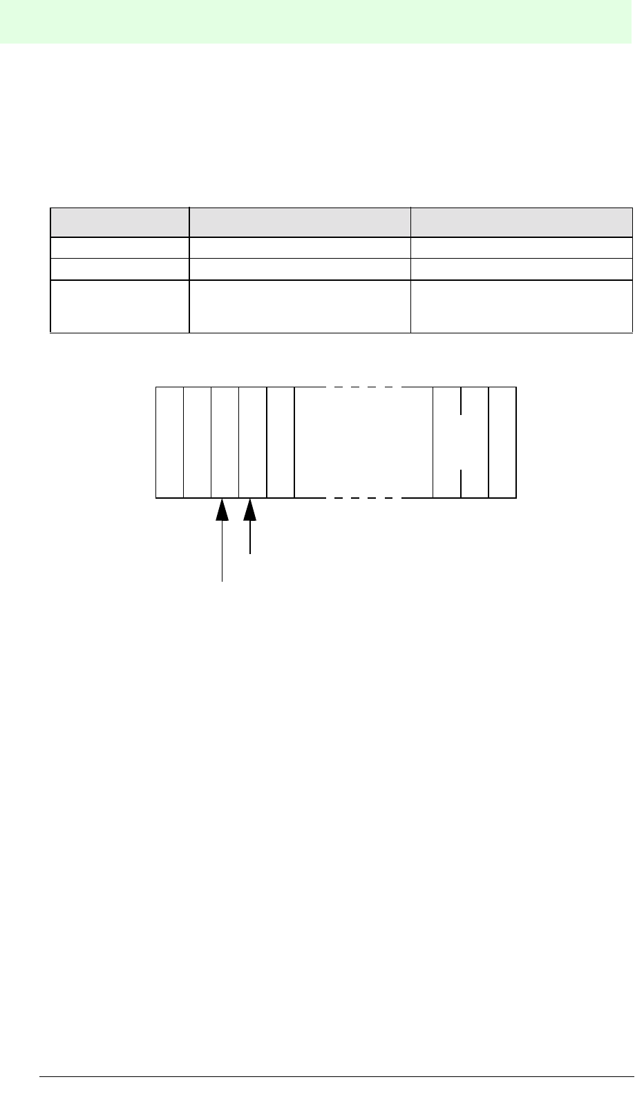
IDENT-M System V
Commands
Date of issue 03.05.2001
124
Subject to reasonable modifications due to technical advances. Copyright Pepperl+Fuchs, Printed in Germany
Pepperl+Fuchs Group • Tel.: Germany (06 21) 7 76-0 • USA (330) 4 25 35 55 • Singapore 7 79 90 91 • Internet http://www.pepperl-fuchs.com
9.2.4 Allocation of the Read/Write Head Scan System
In order to set the station number of the read/write head scan system, enter the station
number and the read/write head numbers and execute the following functions. For
information concerning connection method, switch setting, type of transmission and
functions see the following pages.
Command setting
Item Station number Setting read/write head number
Command 0 (fixed) * (fixed)
Acknowledgement 0 (fixed) * (fixed)
End message
MVI-D2-2HRX station number,
which completes the process with
the data carrier
MVI-D2-2HRX read/write head
number, which completes the
process with the data carrier
S
(H)
C
S
(L)
C
0R
C
?
Command
contents
:: *
Read/write head number
Station number
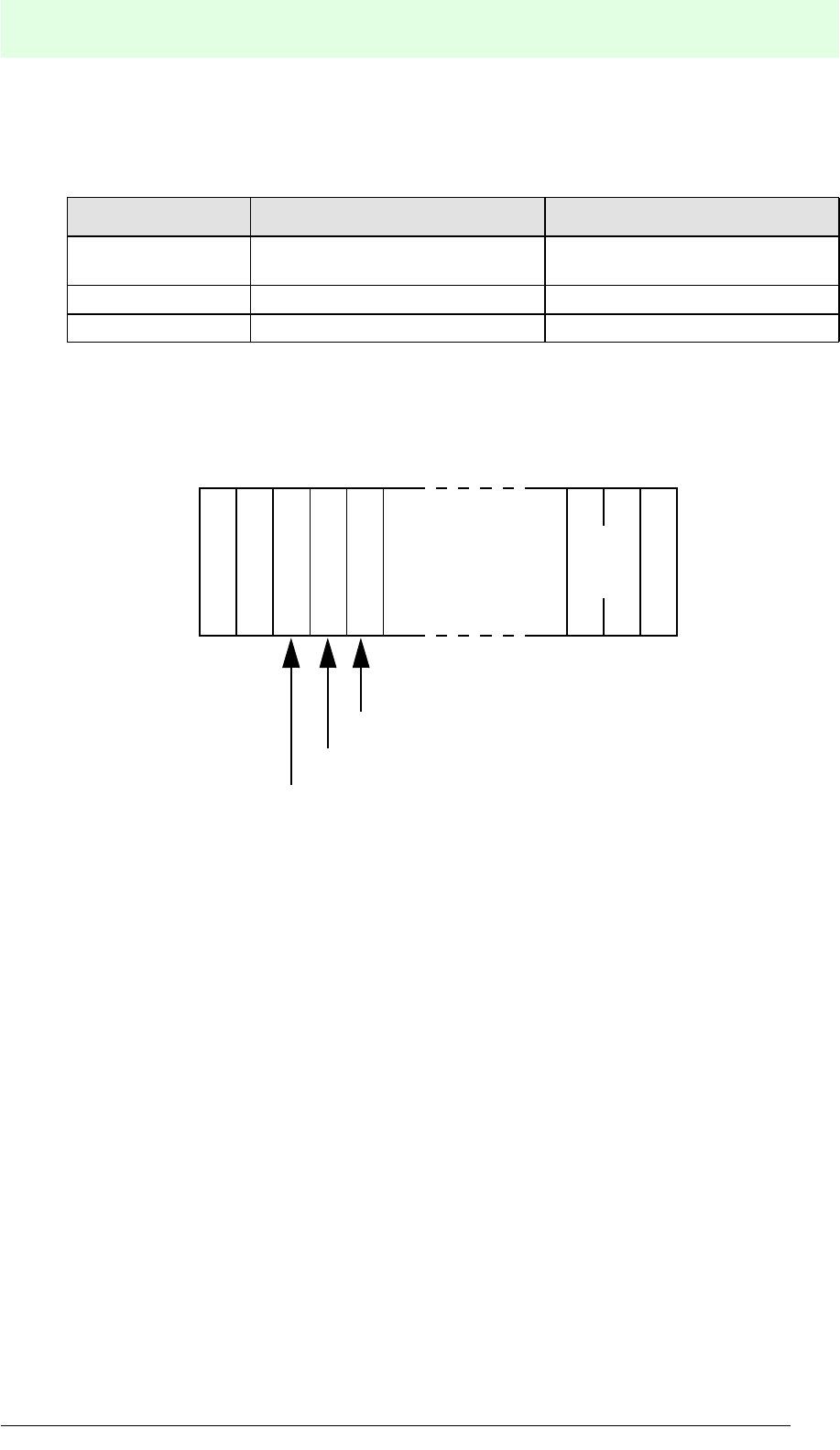
IDENT-M System V
Commands
Date of issue 03.05.2001
125
Subject to reasonable modifications due to technical advances. Copyright Pepperl+Fuchs, Printed in Germany
Pepperl+Fuchs Group • Tel.: Germany (06 21) 7 76-0 • USA (330) 4 25 35 55 • Singapore 7 79 90 91 • Internet http://www.pepperl-fuchs.com
9.2.5 Accessing a Specific Read/Write Head of a Specific Station
Via MVI-D2-2HRX with station number “0”
Example command setting:
Accessing a data carrier in front of read/write head number 1 of MVI-D2-2HRX station
number “2”.
Item Station number Setting read/write head number
Command Each station number connected to
station number “0”. 0 or 1
Acknowledgement same as above same as above
End message same as above same as above
S
(H)
C
S
(L)
C
2R
C
?
Command
contents
:: 1
Station number
Read/write head number
Command code
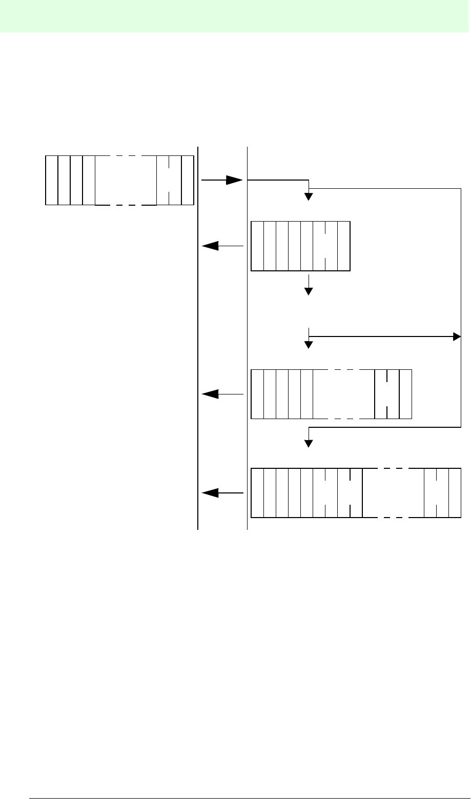
IDENT-M System V
Commands
Date of issue 03.05.2001
126
Subject to reasonable modifications due to technical advances. Copyright Pepperl+Fuchs, Printed in Germany
Pepperl+Fuchs Group • Tel.: Germany (06 21) 7 76-0 • USA (330) 4 25 35 55 • Singapore 7 79 90 91 • Internet http://www.pepperl-fuchs.com
9.3 Command Sets of the Transmission Systems
9.3.1 Occasional Execution System + Auto Response System
Com-
mand
contents
S
A
T
A
T
N
::
S
(H)
C
S
(L)
CR
C
S
A
T
A
T
N
::
S
(H)
C
S
(L)
CR
C
$
Error message
Execute command (e.g. communication
with a data carrier)
S
A
T
A
T
N
::
S
(H)
C
S
(L)
CR
C
#
S
A
T
A
T
N
::
S
(H)
C
S
(L)
CR
C
%
E
(H)
K
E
(L)
K
E
(L)
C
E
(H)
C
OK
OK
NG
NG
Acknowledgement
Host MVI-D2-2HRX
End message
Result
Error
informa-
tion
Command
Error messages are
indicated when errors
occur during the acknowl-
edgement or the end
message.
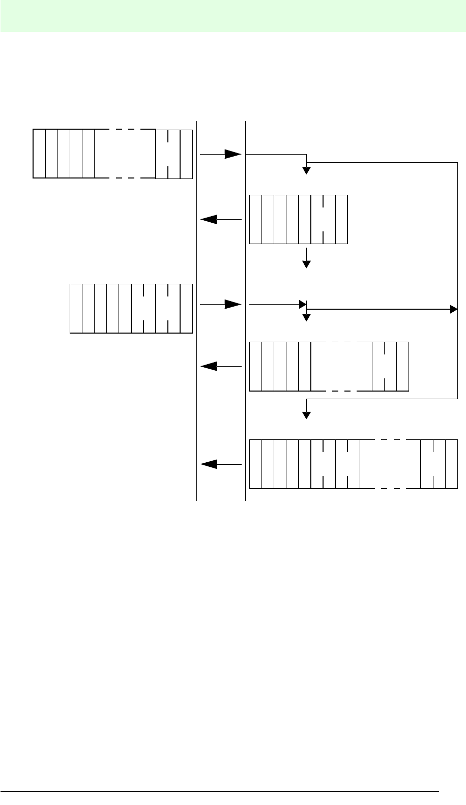
IDENT-M System V
Commands
Date of issue 03.05.2001
127
Subject to reasonable modifications due to technical advances. Copyright Pepperl+Fuchs, Printed in Germany
Pepperl+Fuchs Group • Tel.: Germany (06 21) 7 76-0 • USA (330) 4 25 35 55 • Singapore 7 79 90 91 • Internet http://www.pepperl-fuchs.com
9.3.2 Occasional Execution System + Response Request System
S
A
T
A
T
N?
::
S
(H)
C
S
(L)
CR
C
S
A
T
A
T
N
::
S
(H)
C
S
(L)
CR
C
$
Error message
Execute command (e.g. communication
with a data carrier)
S
A
T
A
T
N
::
S
(H)
C
S
(L)
CR
C
#
S
A
T
A
T
N
::
S
(H)
C
S
(L)
CR
C
%
E
(H)
K
E
(L)
K
E
(L)
C
E
(H)
C
OK
OK
NG
NG
End message
Acknowledgement
Com-
mand
contents
Result
Error
informa-
tion
71
S
(H)
C
S
(L)
CR
C
S
A
T
A
T
N?
::
Error messages are
indicated when errors
occur during the
acknowledgement or the
end message.
Command
Acknowledgement request
Host MVI-D2-2HRX
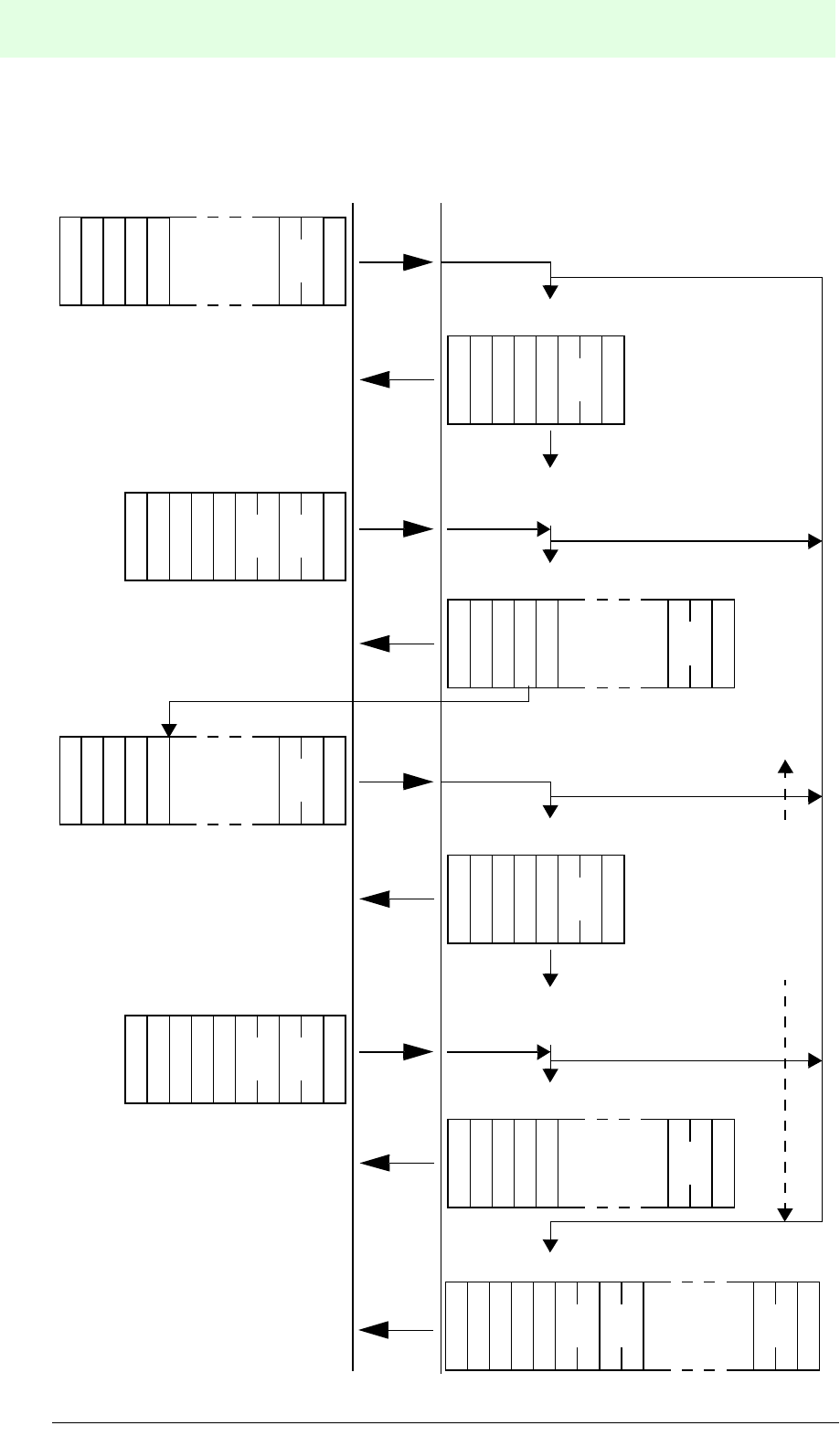
IDENT-M System V
Commands
Date of issue 03.05.2001
128
Subject to reasonable modifications due to technical advances. Copyright Pepperl+Fuchs, Printed in Germany
Pepperl+Fuchs Group • Tel.: Germany (06 21) 7 76-0 • USA (330) 4 25 35 55 • Singapore 7 79 90 91 • Internet http://www.pepperl-fuchs.com
9.3.3 Command Stay System + Auto Response System
S
A
T
A
T
N?
::
S
(H)
C
S
(L)
CR
C
S
A
T
A
T
N
::
S
(H)
C
S
(L)
CR
C
$
Error message
Execute command (e.g. communication
with a data carrier)
S
A
T
A
T
N
::
S
(H)
C
S
(L)
CR
C
#
S
A
T
A
T
N
::
S
(H)
C
S
(L)
CR
C
%
E
(H)
K
E
(L)
K
E
(L)
C
E
(H)
C
OK
OK
NG
NG
End message
Acknowledgement
Com-
mand
contents
Result
Error
informa-
tion
S
A
T
A
T
N?
::
S
(H)
C
S
(L)
CR
C
S
A
T
A
T
N
::
S
(H)
C
S
(L)
CR
C
$
Execute command (e.g. communication
with a data carrier)
S
A
T
A
T
N
::
S
(H)
C
S
(L)
CR
C
#
OK
OK
NG
NG
End response
Acknowledgement
Com-
mand
contents
Result
71
S
(H)
C
S
(L)
CR
C
S
A
T
A
T
N?
::
Command
Error messages are
indicated when errors
occur during the acknowl-
edgement or the end
message.
[Trigger input ON]
Command
Switches on
the
occasional
execution
system while
the trigger
input is ON.
Host MVI-D2-2HRX
71
S
(H)
C
S
(L)
CR
C
S
A
T
A
T
N?
::
Acknowledgement request
Acknowledgement request
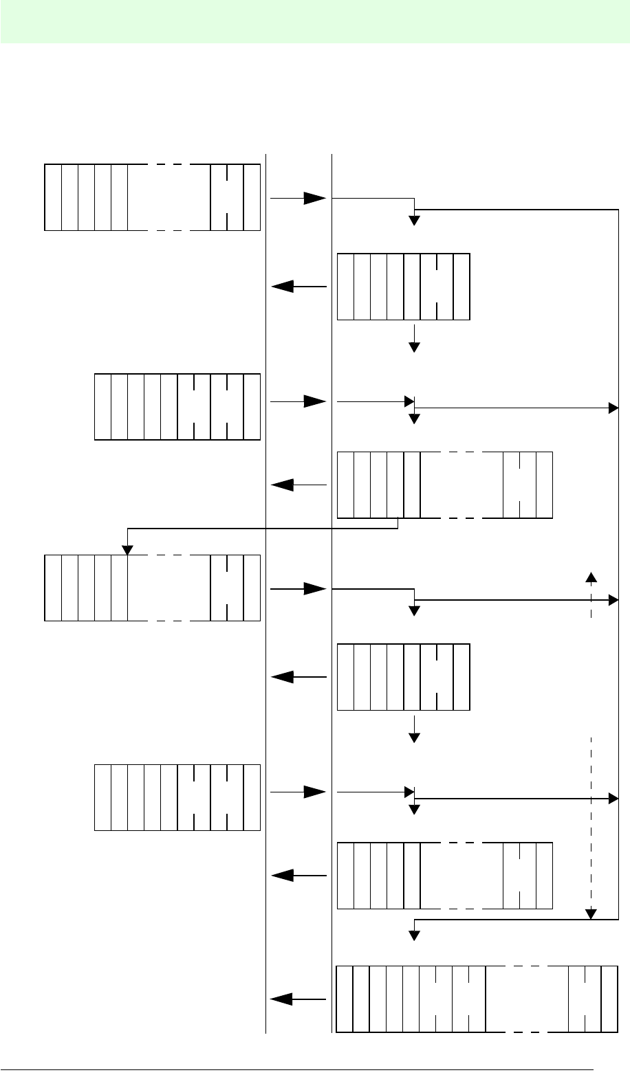
IDENT-M System V
Commands
Date of issue 03.05.2001
129
Subject to reasonable modifications due to technical advances. Copyright Pepperl+Fuchs, Printed in Germany
Pepperl+Fuchs Group • Tel.: Germany (06 21) 7 76-0 • USA (330) 4 25 35 55 • Singapore 7 79 90 91 • Internet http://www.pepperl-fuchs.com
9.3.4 Command Stay System + Response Request System
S
A
T
A
T
N?
::
S
(H)
C
S
(L)
CR
C
S
A
T
A
T
N
::
S
(H)
C
S
(L)
CR
C
$
Error message
Execute command (e.g. communication
with a data carrier)
S
A
T
A
T
N
::
S
(H)
C
S
(L)
CR
C
#
S
A
T
A
T
N
::
S
(H)
C
S
(L)
CR
C
%
E
(H)
K
E
(L)
K
E
(L)
C
E
(H)
C
OK
OK
NG
NG
End message
Acknowledgement
Com-
mand
contents
Result
Error
informa-
tion
71
S
(H)
C
S
(L)
CR
C
S
A
T
A
T
N?
::
S
A
T
A
T
N?
::
S
(H)
C
S
(L)
CR
C
S
A
T
A
T
N
::
S
(H)
C
S
(L)
CR
C
$
Execute command (e.g. communication
with a data carrier)
S
A
T
A
T
N
::
S
(H)
C
S
(L)
CR
C
#
OK
OK
NG
NG
Acknowledgement request
Acknowledgement
Com-
mand
contents
Result
71
S
(H)
C
S
(L)
CR
C
S
A
T
A
T
N?
::
Command
Error messages are
indicated when errors
occur during the acknowl-
edgement or the end
message.
Acknowledgement request
Command
Acknowledgement request
Switches on
the
occasional
execution
system while
the trigger
input is ON.
[Trigger input ON]
Host MVI-D2-2HRX
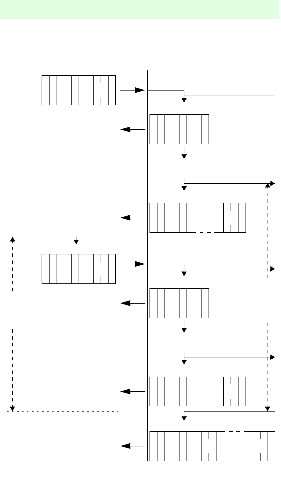
IDENT-M System V
Commands
Date of issue 03.05.2001
130
Subject to reasonable modifications due to technical advances. Copyright Pepperl+Fuchs, Printed in Germany
Pepperl+Fuchs Group • Tel.: Germany (06 21) 7 76-0 • USA (330) 4 25 35 55 • Singapore 7 79 90 91 • Internet http://www.pepperl-fuchs.com
9.3.5 Command Register System + Auto Response System
S
A
T
A
T
N?
::
S
(H)
C
S
(L)
CR
C
S
A
T
A
T
N
::
S
(H)
C
S
(L)
CR
C
$
Error message
Execute command (e.g. communication
with a data carrier)
S
A
T
A
T
N
::
S
(H)
C
S
(L)
CR
C
#
S
A
T
A
T
N
::
S
(H)
C
S
(L)
CR
C
%
E
(H)
K
E
(L)
K
E
(L)
C
E
(H)
C
OK
OK
NG
NG
End message (for a stored command)
Acknowledgement
Result
Error
informa-
tion
S
A
T
A
T
N?
::
S
(H)
C
S
(L)
CR
C
S
A
T
A
T
N
::
S
(H)
C
S
(L)
CR
C
$
Execute command (e.g. communication
with a data carrier)
S
A
T
A
T
N
::
S
(H)
C
S
(L)
CR
C
#
OK
OK
NG
NG
End message (for a stored command)
Acknowledgement
Result
S
(H)
C
S
(L)
CR
C
Command (when trigger input is ON)
Error messages are
indicated when errors
occur during the acknowl-
edgement or the end
message.
Start next command
75
[Trigger input ON]
Repeat at
each turn
ON of the
trigger
input
Enables
commands
as long as
the trigger
input is ON.
67
Host MVI-D2-2HRX
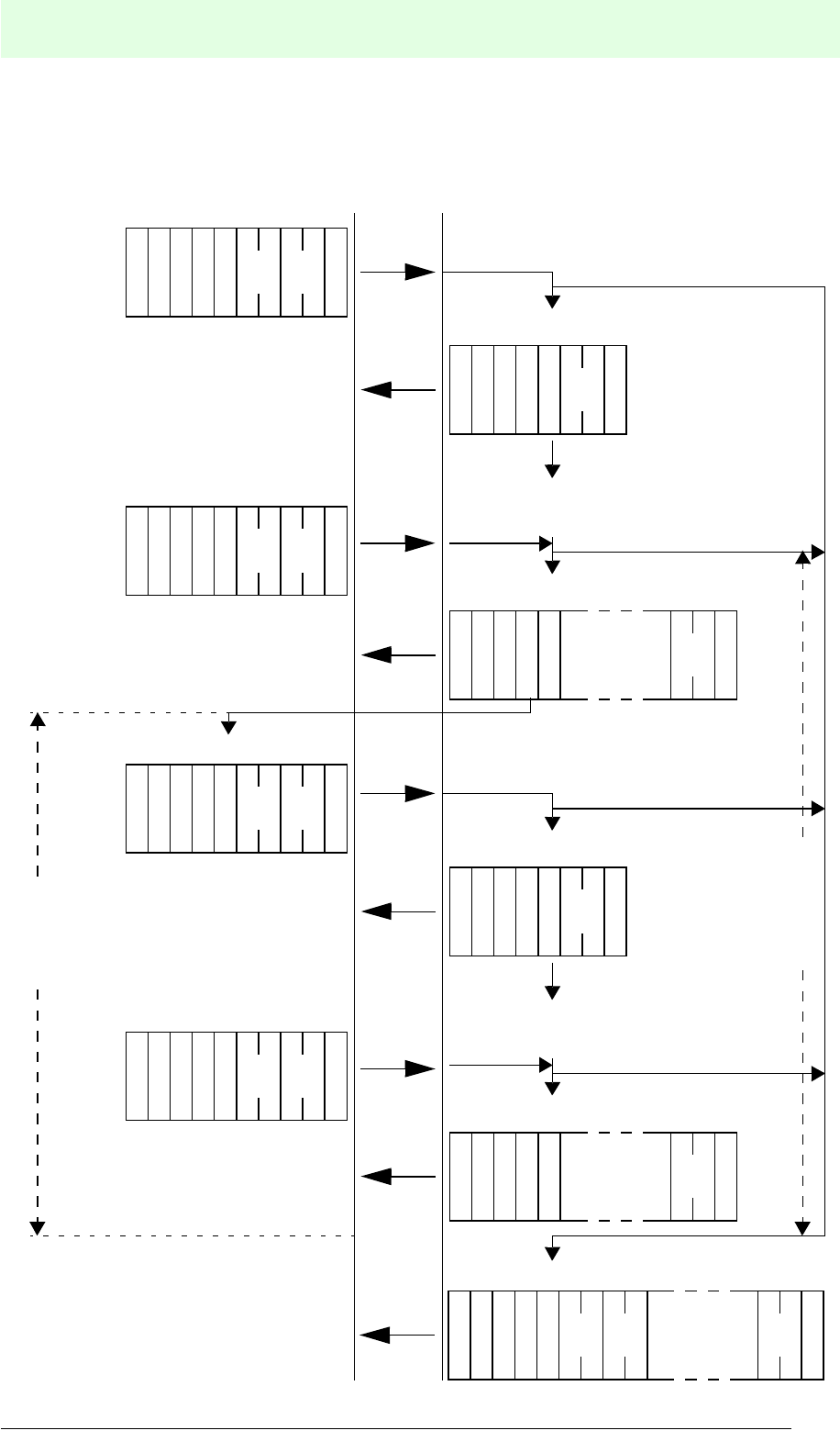
IDENT-M System V
Commands
Date of issue 03.05.2001
131
Subject to reasonable modifications due to technical advances. Copyright Pepperl+Fuchs, Printed in Germany
Pepperl+Fuchs Group • Tel.: Germany (06 21) 7 76-0 • USA (330) 4 25 35 55 • Singapore 7 79 90 91 • Internet http://www.pepperl-fuchs.com
9.3.6 Command Register System + Response Request System
S
A
T
A
T
N?
::
S
(H)
C
S
(L)
CR
C
S
A
T
A
T
N
::
S
(H)
C
S
(L)
CR
C
$
Error message
Execute command (e.g. communication
with a data carrier)
S
A
T
A
T
N
::
S
(H)
C
S
(L)
CR
C
#
S
A
T
A
T
N
::
S
(H)
C
S
(L)
CR
C
%
E
(H)
K
E
(L)
K
E
(L)
C
E
(H)
C
OK
OK
NG
NG
End message (for a stored command)
Acknowledgement
Result
Error
informa-
tion
S
A
T
A
T
N?
::
S
(H)
C
S
(L)
CR
C
S
A
T
A
T
N
::
S
(H)
C
S
(L)
CR
C
$
Execute command (e.g. communication
with a data carrier)
S
A
T
A
T
N
::
S
(H)
C
S
(L)
CR
C
#
OK
OK
NG
NG
End message (for a stored command)
Acknowledgement
Result
S
(H)
C
S
(L)
CR
C
Command (when trigger input is ON)
Error messages are
indicated when errors
occur during the acknowl-
edgement or the end
message.
Start next command
75
[Trigger input ON]
Repeat at
each turn
ON of the
trigger input
Enables
commands
as long as
the trigger
input is ON.
67
71
S
(H)
C
S
(L)
CR
C
S
A
T
A
T
N?
::
Acknowledgement request
Host MVI-D2-2HRX
71
S
(H)
C
S
(L)
CR
C
S
A
T
A
T
N?
::
Acknowledgement request
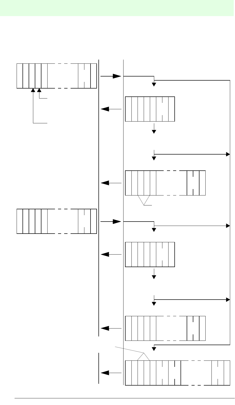
IDENT-M System V
Commands
Date of issue 03.05.2001
132
Subject to reasonable modifications due to technical advances. Copyright Pepperl+Fuchs, Printed in Germany
Pepperl+Fuchs Group • Tel.: Germany (06 21) 7 76-0 • USA (330) 4 25 35 55 • Singapore 7 79 90 91 • Internet http://www.pepperl-fuchs.com
9.3.7 Read/Write Head System + Auto Response System
?::
S
(H)
C
S
(L)
CR
C
S
A
T
A
T
N
::
S
(H)
C
S
(L)
CR
C
$
Error message
Execute command (e.g. communication
with a data carrier)
S
A
T
A
T
N
::
S
(H)
C
S
(L)
CR
C
#
S
A
T
A
T
N
::
S
(H)
C
S
(L)
CR
C
%
E
(L)
K
E
(H)
K
E
(L)
C
E
(H)
C
OK
OK
NG
NG
End message
Acknowledgement
Com-
mand
contents
Result
Error
informa-
tion
S
A
T
A
T
N?
::
S
(H)
C
S
(L)
CR
C
S
A
T
A
T
N
::
S
(H)
C
S
(L)
CR
C
$
Execute command (e.g. communication
with a data carrier)
S
A
T
A
T
N
::
S
(H)
C
S
(L)
CR
C
#
OK
OK
NG
NG
End message
Acknowledgement
Com-
mand
contents
Result
0 *
Command (for operation with a
specific read/write head of a
specific station)
Read/write head
scan instruction
Fixed station
number “0”
Station number and read/write
head number of last station (via
station number “0”)
Note: Connected to the host
controller via station number “0”
Error messages are indicated
when errors occur during the
acknowledgement or the end
message.
Station number and read/write
head number of last station (via
station number “0”)
Command
Host MVI-D2-2HRX
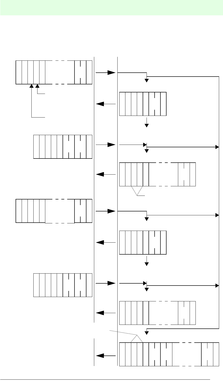
IDENT-M System V
Commands
Date of issue 03.05.2001
133
Subject to reasonable modifications due to technical advances. Copyright Pepperl+Fuchs, Printed in Germany
Pepperl+Fuchs Group • Tel.: Germany (06 21) 7 76-0 • USA (330) 4 25 35 55 • Singapore 7 79 90 91 • Internet http://www.pepperl-fuchs.com
9.3.8 Read/Write Head Scan System + Response Request System
?::
S
(H)
C
S
(L)
CR
C
S
A
T
A
T
N
::
S
(H)
C
S
(L)
CR
C
$
Error message
Execute command (e.g. communication
with a data carrier)
S
A
T
A
T
N
::
S
(H)
C
S
(L)
CR
C
#
S
A
T
A
T
N
::
S
(H)
C
S
(L)
CR
C
%
E
(L)
K
E
(H)
K
E
(L)
C
E
(H)
C
OK NG
NG
End message
Acknowledgement
Com-
mand
contents
Result
Error
informa-
tion
S
A
T
A
T
N?
::
S
(H)
C
S
(L)
CR
C
S
A
T
A
T
N
::
S
(H)
C
S
(L)
CR
C
$
Execute command (e.g. communication
with a data carrier)
S
A
T
A
T
N
::
S
(H)
C
S
(L)
CR
C
#
OK
OK
NG
NG
End message
Acknowledgement
Com-
mand
contents
Result
71
S
(H)
C
S
(L)
CR
C
S
A
T
A
T
N?
::
0 *
Command (for operation with a
specific read/write head of a
specific station)
Read/write head
scan instruction
Fixed station
number “0”
Station number and read/write
head number of last station (via
station number “0”)
Note: Connected to the host
controller via station number “0”
Error messages are indicated
when errors occur during the
acknowledgement or the end
message.
Station number and read/write
head number of last station (via
station number “0”)
OK
71
S
C
S
(L)
CR
C
S
A
T
A
T
N?
::
Acknowledgement request
Command
Host MVI-D2-2HRX
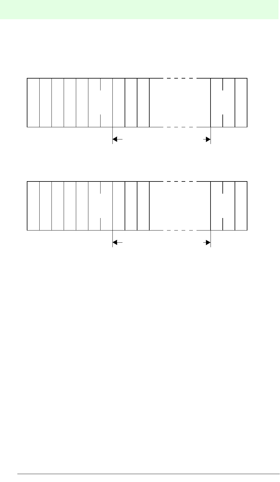
IDENT-M System V
Commands
Date of issue 03.05.2001
134
Subject to reasonable modifications due to technical advances. Copyright Pepperl+Fuchs, Printed in Germany
Pepperl+Fuchs Group • Tel.: Germany (06 21) 7 76-0 • USA (330) 4 25 35 55 • Singapore 7 79 90 91 • Internet http://www.pepperl-fuchs.com
9.4 Commands and End Messages
9.4.1 General Format
Command
End message
9.4.2 General Commands
Register (Coded with an ASCII-Character)
Number of the transmission function's memory area in the command register system.
• Specify the destination number for the command which stores the function
(system memory or MVI-D2-2HRX).
• Codes 1 to 8 are available for setting (number of each memory area).
• The data carrier access function represents a transmission function which can be
stored.
• The stored transmission function is a function, which is enabled by the 75h
command.
Transmission code: Contents of the transmission function to instruct the MVI-
D2-2HRX.
Register: For allocating the storage destination of the transmission
function within the command register system.
PRO: For setting the data protection and the destination after the
writing process.
Attribute: Start mode for communication with a data carrier.
S
A
T
A
T
N
S
(H)
C
S
(L)
CR
C
?
::
P
O
R
Comm.
code
Register
Attribut
Addresses,
number of bytes,
ID codes etc.
Contents depending on
communication command
S
A
T
A
T
N
S
(H)
C
S
(L)
CR
C
#
::
P
O
R
Comm.
code
Register
Attribut
Addresses,
number of bytes,
ID codes etc.
Contents depending on
communication command

IDENT-M System V
Commands
Date of issue 03.05.2001
135
Subject to reasonable modifications due to technical advances. Copyright Pepperl+Fuchs, Printed in Germany
Pepperl+Fuchs Group • Tel.: Germany (06 21) 7 76-0 • USA (330) 4 25 35 55 • Singapore 7 79 90 91 • Internet http://www.pepperl-fuchs.com
PRO: Setting the Save Areas (Coded as ASCII Character)
This function protects the data written in a data carrier from inadvertently being
overwritten.
• After writing data to a data carrier, the MVI-D2-2HRX automatically sets the
desired write-protected area (starting address and number of bytes) to the preset
write-protected area of the data carrier.
• Number of the desired write-protected area (protection from 1 to A (10 positions)
for MVC-60-64K)
• Setting code:
• List of commands which can be write-protected.
Notes:
• The protection setting of a copy command is intended for the destination of the
copied data on the data carrier.
• For commands, other than the above mentioned, set: “*” (no protection).
Attributes of the Communication Start System (Between Read/Write Head and
Data Carrier)
The attribute determines whether the data carrier detection time shall be limited
(single read) or unlimited (auto read). Moreover, it determines whether all data
carriers, data carriers with specific or data carriers with other ID codes shall be
activated. The attribute also determines whether the end message is to be sent with
or without the ID code.
Data carrier detection method:
At the start of communication with a data carrier, the data carrier should be within the
transmission range of a read/write head. In order to detect a data carrier within the
transmission area both an external switch (auto read) and a read/write head (single
read) can be used. For setting see page 138.
1 to A Protection after writing
* No protection after writing
Transmission function code
Write 20
Write and check 21
Write ID code 22
Write data from MVI-D2-2HRX to data carrier 23
Write and check data from MVI-D2-2HRX to data carrier 24
Clear 30
Copy data between read/write heads 40
Copy and check data between read/write heads 41

IDENT-M System V
Commands
Date of issue 03.05.2001
136
Subject to reasonable modifications due to technical advances. Copyright Pepperl+Fuchs, Printed in Germany
Pepperl+Fuchs Group • Tel.: Germany (06 21) 7 76-0 • USA (330) 4 25 35 55 • Singapore 7 79 90 91 • Internet http://www.pepperl-fuchs.com
The transmission limitation time is stored in the MVI-D2-2HRX memory (address:
9000h).
ID Code Allocation
When different types of ID codes are stored in the data carriers, it is possible to
communicate with a data carrier that has a specific ID code by means of commands
with ID code allocation. This data carrier can also be excluded from communication.
• ID code storage position: Memory address 8040hto 8043h of the data carrier.
• ID code setting value: 1 to 4.294.967.296
• It should be noted that ID codes do not occur twice.
• For the allocated function and non-function, set the ID code in the command for
allocation.
Data carrier detection
method Contents
Single read
Detects the presence of a data carrier within the transmission
area by means of a signal from an external switch (e.g.
proximity switch) and then starts the transmission.
Auto read
The read/write head constantly tries to detect a data carrier.
The read/write head automatically starts transmission when
the data carrier is within the transmission area.
Data carrier
detection method
Transmission limitation
time = 0
Transmission limitation
time > 0
Single read
Fixed transmission limitation time
(from the start to the end of the
transmission)
Variable transmission limitation
time (from the start to the end of
the transmission)
Auto read Fixed transmission limitation time
after detecting the data carrier
Variable transmission limitation
time after detecting the data
carrier
ID code allocation Contents
Without allocation The read/write head communicates with each data carrier in
the transmission area.
With
allocation
Allocated
function
Set the ID code in the command by the host controller. The
read/write head does only communicate with the allocated data
carrier.
Allocated non-
function
Set the ID code in the command by the host controller. The
read/write head communicates with other than the allocated
data carrier.

IDENT-M System V
Commands
Date of issue 03.05.2001
137
Subject to reasonable modifications due to technical advances. Copyright Pepperl+Fuchs, Printed in Germany
Pepperl+Fuchs Group • Tel.: Germany (06 21) 7 76-0 • USA (330) 4 25 35 55 • Singapore 7 79 90 91 • Internet http://www.pepperl-fuchs.com
Ex.: When the read/write head starts transmission to data carriers and when there are
three data carriers within the transmission area.
1. When selecting “without ID code allocation” an error message occurs, which
indicates that there is no data carrier within the transmission area.
2. When the ID code is set to “1” together with “allocated function” and with “ID code
allocation”, the read/write head does only communicate with the data carrier of
pallet 1 and no transmission error is indicated.
3. When the ID code is set to “1” together with “allocated non-function” and with “ID
code allocation”, the read/write head does only communicate with the data
carriers of pallets 2 and 3. “No data carrier error” is indicated together with the
transmission error.
Allocation of the ID Code Return
In the case of a response to the host controller, this function serves to return the ID
codes of the accessed data carriers. When returning the ID code, the response
becomes 4 bytes (8 ASCII characters) longer than without ID code return.
Pallet 1 Pallet 3Pallet 2
Read/
write head
Data carrier
Data carrier
Data carrier
Transmission area
(ID code: 1)
(ID code: 2)
(ID code: 3)

IDENT-M System V
Commands
Date of issue 03.05.2001
138
Subject to reasonable modifications due to technical advances. Copyright Pepperl+Fuchs, Printed in Germany
Pepperl+Fuchs Group • Tel.: Germany (06 21) 7 76-0 • USA (330) 4 25 35 55 • Singapore 7 79 90 91 • Internet http://www.pepperl-fuchs.com
Setting the Attributes
Selection values of the communication start system and the ID code returns between
a read/write head and data carriers are referred to as attribute codes.
• The attribute code consists of detection method, ID code allocation and allocation
of ID code return/non-return.
• The attribute code is represented by one ASCII character.
• When ID codes allocate function or non-function, they should be set in the
command (ID code setting position is described at each message of the
transmission function).
• If no ID code is allocated, an ID code setting for the command is not required.
• Attribute code
Communication startup system Attribute code (ASCII code)
Notes
Data carrier
detection
method
ID code
allocation
Without ID
code return
With ID code
return
Single read
None 0 A -
Allocated
function 1B
ID code must be set
in the command.
Allocated
non-function 2C
Auto read
None 3 D -
Allocated
function 4E
ID code must be set
in the command.
Allocated
non-function 5F

IDENT-M System V
Commands
Date of issue 03.05.2001
139
Subject to reasonable modifications due to technical advances. Copyright Pepperl+Fuchs, Printed in Germany
Pepperl+Fuchs Group • Tel.: Germany (06 21) 7 76-0 • USA (330) 4 25 35 55 • Singapore 7 79 90 91 • Internet http://www.pepperl-fuchs.com
Setting Range of the Transmission Function
Setting position
The transmission area is given in terms of a starting address and the number of bytes.
Hexadecimal numbers in ASCII code (4 bytes) are used for the setting.
•Format
• Some areas in the data carrier's system area (8000h and after) as well as the MVI-
D2-2HRX system area (9000h and after) can neither be read nor written upon.
• All data of the data carrier's data area (MVC-60-64K: 0000h to lD7Fh) can be
written and read. However, the write function is not available for write-protected
areas.
• Set addresses
Data carrier
Control interface unit:
• Data carrier buffer area: same as the above mentioned data carrier.
• System area for data carrier transmission: 9000hto 9D81h
• MVI-D2-2HRX special system area: A000hto A00Bh
Data carrier
MVC-60-64K,
MVC-60B-64K MVC-60-256K
Data area Number of bytes 7552 30976
Address (hexadecimal) 0000
....
1D7F
0000
...
78FF
System area Number of bytes 126 126
Address (hexadecimal) 8000
...
807D
8000
...
807D
Start
address
Number of
bytes

IDENT-M System V
Commands
Date of issue 03.05.2001
140
Subject to reasonable modifications due to technical advances. Copyright Pepperl+Fuchs, Printed in Germany
Pepperl+Fuchs Group • Tel.: Germany (06 21) 7 76-0 • USA (330) 4 25 35 55 • Singapore 7 79 90 91 • Internet http://www.pepperl-fuchs.com
Setting Range:
The maximum number of bytes is different for each transmission function.
Transmission function Classifi-
cationa
a. “P” denotes the data carrier access function,
“C” denotes the MVI-D2-2HRX access function.
Transm.
code
(hex.)
Max. number of
bytes
MVC-60*-
64K
MVC-60-
256K
Read
Read P 10 512
Read and check P 11 512
Read data from data carrier
to MVI-D2-2HRX. P 13 7552 30976
Read and check data from data carrier
to MVI-D2-2HRX P 14 7552 30976
Read MVI-D2-2HRX P 15 512
Write
Write P 20 512
Write and check P 21 512
Write data from MVI-D2-2HRX to data
carrier P 23 7552 30976
Write and check data from MVI-D2-
2HRX to data carrier P 24 7552 30976
Write MVI-D2-2HRX C 25 512
Clear
Clear P 30 7552 30976
Clear MVI-D2-2HRX C 35 7552 30976
Copy
Copy data between read/write heads P 40 7552 30976
Copy and check data between read/
write heads P 41 7552 30976
Diagnosis
Self-diagnosis of data carrierb
b. The indicated setting range applies to the RAM check.
P 50 7552 30976
RAM check P 52 7552 30976
Block check P 60 7552 30976

IDENT-M System V
Commands
Date of issue 03.05.2001
141
Subject to reasonable modifications due to technical advances. Copyright Pepperl+Fuchs, Printed in Germany
Pepperl+Fuchs Group • Tel.: Germany (06 21) 7 76-0 • USA (330) 4 25 35 55 • Singapore 7 79 90 91 • Internet http://www.pepperl-fuchs.com
When transferring data of more than 512 bytes, please proceed in the following way:
From Data Carrier to Host Controller
• Repeated reading of data with up to 512 bytes by means of the read instruction
(10h).
• Combine the MVI-D2-2HRX read instruction (15h) with reading from the data
carrier to the MVI-D2-2HRX (command 13h) or with reading and checking from
the data carrier to the MVI-D2-2HRX (command 14h).
Read data from the data carrier to the MVI-D2-2HRX data carrier buffer together with
the data carrier's read data (with check) to the MVI-D2-2HRX (max. 7552 or 30976
bytes).
Read data “n” times in units of 512 bytes by means of the MVI-D2-2HRX read
instruction from the host controller to the MVI-D2-2HRX data carrier memory, at any
point in time. (However, the data quantity might be less than 512 bytes during the last
transmission).
From Host Controller to Data Carrier
• Repeat writing of data with up to 512 bytes by means of the write instruction (20h).
• Combine the MVI-D2-2HRX write instruction (25h) with writing from the MVI-D2-
2HRX to the data carrier command (23h) or with writing and checking from the
MVI-D2-2HRX to the data carrier command (24h).
Write data with “n” times 512 bytes from the host controller to the data carrier buffer
by means of the MVI-D2-2HRX write instruction, before the data carrier arrives.
(However, the data quantity might be less than 512 bytes during the last
transmission).
On arrival of the data carrier, the data stored in the MVI-D2-2HRX data carrier buffer
are written on the data carrier containing the write data (with check) of the MVI-D2-
2HRX (max. 7552 or 30976 bytes).
Setting the Data Format
Data Code (DCD)
Two types of characters are available for the data code: hexadecimal ASCII code and
one byte JIS code.
• Enter one digit of an alphabetical ASCII character to select the data code.
• Both (3Ah) and CR (ODh) can be used to write and clear data with one byte JIS
character.
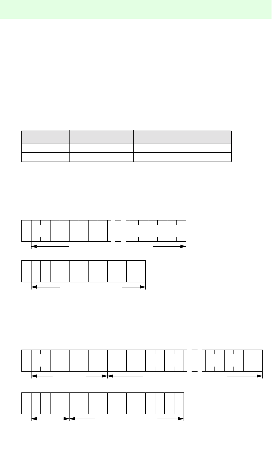
IDENT-M System V
Commands
Date of issue 03.05.2001
142
Subject to reasonable modifications due to technical advances. Copyright Pepperl+Fuchs, Printed in Germany
Pepperl+Fuchs Group • Tel.: Germany (06 21) 7 76-0 • USA (330) 4 25 35 55 • Singapore 7 79 90 91 • Internet http://www.pepperl-fuchs.com
Format
• When data is contained in the end message during reading,
set the data code after the number of instruction bytes.
• When data is contained in the end message during writing,
set the data code before the data.
• When the “ID code allocated function/non-function” is selected, the ID code
allocation of the command is also added.
• In the case of “with ID code acknowledgement” the code destination of the ID
code is added to the message.
Format Example
Command: Without ID code allocation
Response: Without ID code message
Command: With ID code allocation
Response: With ID code message
Data code Set value Characters required for one byte
Hexadecimal H Two characters (00 ... FF)
JIS character J One character
23 0
3
3 1 3 2 3 3 3 9 4 1 4
210 7654 A98
H
J B
12 byte data (24 characters)
Data (12 characters)
HH 3 0 3 1 3 2 3 3 3 9 4 1 4 2H 3 0 3 1 3 2 3 3
J
12 byte data (24 characters)ID code
(8 characters)
3210 7654 A983 B
Data (12 characters)
210
ID code
(8 char.)

IDENT-M System V
Commands
Date of issue 03.05.2001
143
Subject to reasonable modifications due to technical advances. Copyright Pepperl+Fuchs, Printed in Germany
Pepperl+Fuchs Group • Tel.: Germany (06 21) 7 76-0 • USA (330) 4 25 35 55 • Singapore 7 79 90 91 • Internet http://www.pepperl-fuchs.com

IDENT-M System V
Overview of Commands
Date of issue 03.05.2001
144
Subject to reasonable modifications due to technical advances. Copyright Pepperl+Fuchs, Printed in Germany
Pepperl+Fuchs Group • Tel.: Germany (06 21) 7 76-0 • USA (330) 4 25 35 55 • Singapore 7 79 90 91 • Internet http://www.pepperl-fuchs.com
9.4.3 Overview of Commands
Read
Read (Transmission Code: 10h) . . . . . . . . . . . . . . . . . . . . . . . . . . . . . . . . . . . . . . . . . . . .146
Read and Check (Transmission Code: 11h) . . . . . . . . . . . . . . . . . . . . . . . . . . . . . . . . . . .146
Reading ID Code (Transmission Code: 12h). . . . . . . . . . . . . . . . . . . . . . . . . . . . . . . . . . .147
Reading Data from Data Carrier to Control Interface Unit
(Transmission Code: 13h) . . . . . . . . . . . . . . . . . . . . . . . . . . . . . . . . . . . . . . . . . . . . . . . . .148
Read and Check Data from Data Carrier to MVI-D2-2HRX
(Transmission Code: 14h) . . . . . . . . . . . . . . . . . . . . . . . . . . . . . . . . . . . . . . . . . . . . . . . . .148
Reading the Control Interface Unit (Transmission Code: 15h) . . . . . . . . . . . . . . . . . . . . .149
Reading the Current Time (Transmission Code: 16h). . . . . . . . . . . . . . . . . . . . . . . . . . . .151
Write
Write (Transmission Code: 20h),. . . . . . . . . . . . . . . . . . . . . . . . . . . . . . . . . . . . . . . . . . . .152
Read and Check (Transmission Code: 21h) . . . . . . . . . . . . . . . . . . . . . . . . . . . . . . . . . . .152
Read ID Code (Transmission Code: 22h) . . . . . . . . . . . . . . . . . . . . . . . . . . . . . . . . . . . . .153
Writing Data into the Data Carrier (Transmission Code: 24h) . . . . . . . . . . . . . . . . . . . . . .154
Writing Data into the Control Interface Unit (Transmission Code: 25h). . . . . . . . . . . . . . .155
Copy
Copy Data between Different Read/Write Heads
(Transmission Code: 40h) . . . . . . . . . . . . . . . . . . . . . . . . . . . . . . . . . . . . . . . . . . . . . . . . .162
Copy and Check Data between Different Read/Write Heads
(Transmission Code: 41h) . . . . . . . . . . . . . . . . . . . . . . . . . . . . . . . . . . . . . . . . . . . . . . . . .162
Diagnostic Commands
Self-Diagnosis of the Data Carrier (Transmission Code: 50h) . . . . . . . . . . . . . . . . . . . . .165
RAM Check (Transmission Code: 52h). . . . . . . . . . . . . . . . . . . . . . . . . . . . . . . . . . . . . . .166
Block Check (Transmission Code: 60h) . . . . . . . . . . . . . . . . . . . . . . . . . . . . . . . . . . . . . .166
ROM Check (Transmission Code: 51h). . . . . . . . . . . . . . . . . . . . . . . . . . . . . . . . . . . . . . .167
Data Carrier's Battery Life Check)
(Transmission Code: 53h) . . . . . . . . . . . . . . . . . . . . . . . . . . . . . . . . . . . . . . . . . . . . . . . . .168
Self-Diagnosis of the MVI-D2-2HRX (Transmission Code: 55h). . . . . . . . . . . . . . . . . . . .168

IDENT-M System V
Overview of Commands
Date of issue 03.05.2001
145
Subject to reasonable modifications due to technical advances. Copyright Pepperl+Fuchs, Printed in Germany
Pepperl+Fuchs Group • Tel.: Germany (06 21) 7 76-0 • USA (330) 4 25 35 55 • Singapore 7 79 90 91 • Internet http://www.pepperl-fuchs.com
Other Functions
Setting the Current Time (Transmission Code: 26h) . . . . . . . . . . . . . . . . . . . . . . . . . . . . 156
Clear (Transmission Code: 30h) . . . . . . . . . . . . . . . . . . . . . . . . . . . . . . . . . . . . . . . . . . . 157
Initialise Data Carrier (Transmission Code: 31h) . . . . . . . . . . . . . . . . . . . . . . . . . . . . . . . 158
Clearing the Data of the Control Interface Unit (Transmission Code: 35h) . . . . . . . . . . . 159
Initialisation of MVI-D2-2HRX (Transmission Code: 36h) . . . . . . . . . . . . . . . . . . . . . . . . 160
Clear Protocol (Transmission Code: 37h) . . . . . . . . . . . . . . . . . . . . . . . . . . . . . . . . . . . . 161
Reset (Transmission Code: 70h) . . . . . . . . . . . . . . . . . . . . . . . . . . . . . . . . . . . . . . . . . . . 169
Result Request (Transmission Code: 71h) . . . . . . . . . . . . . . . . . . . . . . . . . . . . . . . . . . . 169
Output Instruction (Transmission Code: 72h) . . . . . . . . . . . . . . . . . . . . . . . . . . . . . . . . . 170
Read Status (Transmission Code: 73h) . . . . . . . . . . . . . . . . . . . . . . . . . . . . . . . . . . . . . . 170
Stop Function (Transmission Code: 74h). . . . . . . . . . . . . . . . . . . . . . . . . . . . . . . . . . . . . 171
Command when Trigger Input is ON (Transmission Code: 75h) . . . . . . . . . . . . . . . . . . . 171
Start of the Next Command (Transmission Code: 76h) . . . . . . . . . . . . . . . . . . . . . . . . . . 172
Re-execution (Transmission Code: 77h) . . . . . . . . . . . . . . . . . . . . . . . . . . . . . . . . . . . . . 172
IDENT-M System V
Commands
Date of issue 03.05.2001
146
Subject to reasonable modifications due to technical advances. Copyright Pepperl+Fuchs, Printed in Germany
Pepperl+Fuchs Group • Tel.: Germany (06 21) 7 76-0 • USA (330) 4 25 35 55 • Singapore 7 79 90 91 • Internet http://www.pepperl-fuchs.com
9.4.4 File Description of All Commands
Read (Transmission Code: 10h)
Read and Check (Transmission Code: 11h)
This command reads data in a data carrier from a specific starting address with a
specific number of bytes and transfers it to the host controller. The maximum number
of readable bytes is 512.
Command
End message
1) In the case of the occasional execution system, command stay system, or read/write head
scan system, this function sets “*” for the command storage. In this setting the end message
is also stored as “*”.
Data Transmission
S
A
T
A
T
N
:: #Comm.
code
Registration
’
Attribute
Start
address
Number
of bytes
ID code
D
D
C
S
(H)
C
S
(L)
CR
C
1)
1)
S
A
T
A
T
N
:: #Comm.
code
Registration
’
Attribute
Start
address
Number
of bytes
ID code
D
D
C
S
(H)
C
S
(L)
CR
C
Data 1 Data 2 Data n
Selected
number of
bytes (max.
512
bytes)
Start of selected
address
Selected
number of
bytes (max.
512
bytes)
Start of selected
address
Host controller
Memory of MVI-D2-2HRX
(data carrier buffer)
Memory of
data carrier
IDENT-M System V
Commands
Date of issue 03.05.2001
147
Subject to reasonable modifications due to technical advances. Copyright Pepperl+Fuchs, Printed in Germany
Pepperl+Fuchs Group • Tel.: Germany (06 21) 7 76-0 • USA (330) 4 25 35 55 • Singapore 7 79 90 91 • Internet http://www.pepperl-fuchs.com
Reading ID Code (Transmission Code: 12h)
This command reads ID codes (address: 8040hto 8043h, 4 bytes), which are stored
in the data carrier system memory and transfers them to the host controller.
Command
Note: When the attribute is “ID code allocated function/non-function”, the function adds the ID
code at the end of the data code (DCD).
End message
1) In the case of the occasional execution system, command stay system, or read/write head
scan system, this command sets “*” into the command memory. In this setting the command
also stores “*” in the end message.
2) Both data formats, hexadecimals: h, and JIS: j are available.
Hexadecimal: 00000000hto FFFFFFFFh(8 digits)
JIS: Four digits JIS code.
Data Transmission
?
S
(H)
C
S
(L)
CR
C
: :
S
A
T
A
T
N12
Registration
Attribute
*
D
D
C
1) 2)
?
S
(H)
C
S
(L)
CR
C
: :
S
A
T
A
T
N12
Registration
Attribute
*
D
D
CData
ID code
1) 2)
ID code
(4 bytes)
8040h
Host controller
Memory of MVI-D2-2HRX
(data carrier buffer)
Memory of
data carrier
8043h
ID code
(4 bytes)
8040h
8043h
IDENT-M System V
Commands
Date of issue 03.05.2001
148
Subject to reasonable modifications due to technical advances. Copyright Pepperl+Fuchs, Printed in Germany
Pepperl+Fuchs Group • Tel.: Germany (06 21) 7 76-0 • USA (330) 4 25 35 55 • Singapore 7 79 90 91 • Internet http://www.pepperl-fuchs.com
Reading Data from Data Carrier to Control Interface Unit
(Transmission Code: 13h)
Read and check Data from Data Carrier to MVI-D2-2HRX
(Transmission Code: 14h)
This command transmits data from a specific starting address in the data carrier
memory (transmission source data) with a specific number of bytes to a specific
starting address (transmission destination) in the MVI-D2-2HRX data carrier buffer.
The maximum number of readable bytes is 7552.
Command
End message
1) In the case of the occasional execution system, command stay system, or read/write head
scan system, this command sets “*” into the command memory. In this setting the command
also stores “*” in the end message.
2) In the case of “adding ID code message”, it is necessary to set the data code of the ID
code to DCD or to command (hexadecimal: h, JIS: j).
In the case of “without ID code message”, the command sets “*” to DCD of the command.
Data Transmission
In conjunction with the read instruction of the MVI-D2-2HRX (transmission code: 15h)
this command can transmit a multitude of data from a data carrier to a host controller.
1) Read and check data from a data carrier to an MVI-D2-2HRX (max. 7552 or 30976 bytes).
2) Read data from an MVI-D2-2HRX (max. 512 bytes).
?
S
A
T
A
T
N
::
S
(H)
C
S
(L)
CR
C
*
D
D
C
1)
Start address
transm.
destination
(data carrier)
Number
of bytes
Start address
transm. source
(MVI-D2-
2HRX)
ID code
Registration
Attribute
2)
Comm.
code
Omit when attribute is “without ID
code allocation”.
#
S
A
T
A
T
N
::
S
(H)
C
S
(L)
CR
C
*
D
D
C
1)
Start address
transm.
destination
(data carrier)
Number
of bytes
Start address
transm. source
(MVI-D2-
2HRX)
ID code
Registration
Attribute
2)
Comm.
code
Omit when attribute is “without ID
code allocation”.
Selected
number of
bytes (7552 or
max. 30976
bytes )
Selected top
address
Selected
number of
bytes (7552 or
max. 30976
bytes )
Selected top
address
Host controller
Memory of MVI-D2-2HRX
(data carrier buffer)
Memory of
data carrier
1)2)
IDENT-M System V
Commands
Date of issue 03.05.2001
149
Subject to reasonable modifications due to technical advances. Copyright Pepperl+Fuchs, Printed in Germany
Pepperl+Fuchs Group • Tel.: Germany (06 21) 7 76-0 • USA (330) 4 25 35 55 • Singapore 7 79 90 91 • Internet http://www.pepperl-fuchs.com
Reading the Control Interface Unit (Transmission Code: 15h)
This command transmits data from a specific starting address and a specific number
of bytes of the MVI-D2-2HRX (data carrier buffer, system memory) to the host
controller.
• The maximum number of readable bytes is 512.
• When reading data from the MVI-D2-2HRX special area, this command reads
data in the same area regardless of whether the number of the read/write head
command (ANT) is 0 or 1.
Command
End message
Data Transmission
Reading the system memory of the control interface unit
S
(H)
C
S
(L)
C
1?
S
A
T
A
T
N
:: R
C
5
D
D
C
Start
address
Number
of bytes
1#
S
A
T
A
T
N
:: 5
D
D
C
Start
address
Number
of bytes
S
(H)
C
S
(L)
CR
C
Data 1 Data 2 Data n
Selected
number of
bytes (max.
512 bytes)
Start of selected
address
Host controller
Memory of MVI-D2-2HRX
(system memory)
Memory of
data carrier

IDENT-M System V
Commands
Date of issue 03.05.2001
150
Subject to reasonable modifications due to technical advances. Copyright Pepperl+Fuchs, Printed in Germany
Pepperl+Fuchs Group • Tel.: Germany (06 21) 7 76-0 • USA (330) 4 25 35 55 • Singapore 7 79 90 91 • Internet http://www.pepperl-fuchs.com
Together with the command “read and check data” from the data carrier to the MVI-
D2-2HRX, this command can transmit a multitude of data from a data carrier to a host
controller.
1) Read and check data from a data carrier to an MVI-D2-2HRX (max.
7552 or 30976 bytes).
2) Read data from MVI-D2-2HRX (max. 512 bytes).
Selected
number of
bytes (7552 or
max. 30976
bytes )
Start of selected
address
Selected
number of
bytes (7552 or
max. 30976
bytes )
Start of selected
address
Host controller
Memory of MVI-D2-2HRX
(data carrier buffer)
Memory of
data carrier
1)2)
IDENT-M System V
Commands
Date of issue 03.05.2001
151
Subject to reasonable modifications due to technical advances. Copyright Pepperl+Fuchs, Printed in Germany
Pepperl+Fuchs Group • Tel.: Germany (06 21) 7 76-0 • USA (330) 4 25 35 55 • Singapore 7 79 90 91 • Internet http://www.pepperl-fuchs.com
Reading the Current Time (Transmission Code: 16h)
This command transmits the time integrated in the MVI-D2-2HRX system memory
(address: A000h to A0006h, 7 bytes) to the host controller.
Command
End message
This command reads data from the MVI-D2-2HRX system area regardless of whether
the number of the read/write head command (ANT) is 0 or 1.
Both data formats, hexadecimal: h and JIS: j are available.
Data Value:
Data Transmission
Position Value (BCD) Notes
Year 00 ... 99 Without digits indicating the century
Month 01 ... 12
Day 01 ... 31
Weekday 00 ... 06 Sun - Sat = 00 - 06
Hour 00 ... 23
Minute 00 ... 59
Second 00 ... 59
S
(H)
C
S
(L)
C
1?
S
A
T
A
T
N
:: R
C
6
D
D
C
S
(H)
C
S
(L)
C
1#
S
A
T
A
T
N
:: R
C
6
D
D
C
(H) (L)
Year
(H) (L)
Second
(H) (L)
Month
(H) (L)
Day
(H) (L)
Weekd
(H) (L)
Minute
(H) (L)
Hour
Time
(7 bytes)
A000h
Host controller Memory of MVI-D2-2HRX
Memory of
data carrier
A006h
IDENT-M System V
Commands
Date of issue 03.05.2001
152
Subject to reasonable modifications due to technical advances. Copyright Pepperl+Fuchs, Printed in Germany
Pepperl+Fuchs Group • Tel.: Germany (06 21) 7 76-0 • USA (330) 4 25 35 55 • Singapore 7 79 90 91 • Internet http://www.pepperl-fuchs.com
Write (Transmission Code: 20h),
Read and Check (Transmission Code: 21h)
This command transmits data from the host controller to the data carrier memory
within the area of a specific starting address with a specific number of bytes. The
maximum number of available bytes is 512.
Command
End message
1) In the case of the occasional execution system, command stay system, or read/write head
scan system, this command sets “*” into the command memory. In this setting the command
also stores “*” in the end message.
Data Transmission
Transmission
code
1)
S
A
T
A
T
N
:: #
Registration
P
O
R
Attribute
Start
address
Number
of bytes
ID code
D
D
C
S
(H)
C
S
(L)
CR
C
Data 1 Data 2 Data n
Omit when attribute is “without
ID code allocation”.
Transmission
code
1)
S
A
T
A
T
N
:: #
Registration
P
O
R
Attribute
Start
address
Number
of bytes
ID code
D
D
C
S
(H)
C
S
(L)
CR
C
Omit when attribute is “without
ID code allocation”.
Selected
number of
bytes (max.
512 bytes)
Start of selected
address
Selected
number of
bytes (max.
512 bytes)
Start of selected
address
Host controller
Memory of MVI-D2-2HRX
(data carrier buffer)
Memory of
data carrier
IDENT-M System V
Commands
Date of issue 03.05.2001
153
Subject to reasonable modifications due to technical advances. Copyright Pepperl+Fuchs, Printed in Germany
Pepperl+Fuchs Group • Tel.: Germany (06 21) 7 76-0 • USA (330) 4 25 35 55 • Singapore 7 79 90 91 • Internet http://www.pepperl-fuchs.com
Read ID Code (Transmission Code: 22h)
This command writes the ID code from the host controller to the system memory of
the data carrier (address: 8040h to 8043h, 4 bytes).
Note: When the instruction attribute is “ID code allocated function/non-function”, a
new ID code is appended at the end of the data code (DCD).
Command
End message
1) In the case of the occasional execution system, command stay system, or read/write head
scan system, this command sets “*” into the command memory. In this setting the command
also stores “*” in the end message.
2) Both data formats, hexadecimal: h and JIS: j are available.
Hexadecimal: 00000000 to FFFFFFFF (8 digits)
JIS: 4 digits JIS code.
Note: When the instruction attribute is “ID code acknowledgement”, a new ID code is
appended at the end of the data code (DCD).
Data Transmission
?
S
(H)
C
S
(L)
CR
C
: :
S
A
T
A
T
N22
Registration
Attribute
D
D
CID code
1) 2)
P
O
R
?
S
(H)
C
S
(L)
CR
C
: :
S
A
T
A
T
N22
Registration
Attribute
D
D
C
1) 2)
P
O
R
ID code
(4 bytes)
8040h
Host controller
Memory of MVI-D2-2HRX
(data carrier buffer)
Memory of
data carrier
8043h
ID code
(4 bytes)
8040h
8043h
IDENT-M System V
Commands
Date of issue 03.05.2001
154
Subject to reasonable modifications due to technical advances. Copyright Pepperl+Fuchs, Printed in Germany
Pepperl+Fuchs Group • Tel.: Germany (06 21) 7 76-0 • USA (330) 4 25 35 55 • Singapore 7 79 90 91 • Internet http://www.pepperl-fuchs.com
Writing Data into the Data Carrier (Transmission Code: 24h)
These commands transmit data within the MVI-D2-2HRX data carrier buffer from a
specific starting address (transmission source data) to another specific starting
address in a data carrier using a specified number of bytes. The maximum number of
writable bytes is 7552 or 30976.
Command
End message
1) In the case of the occasional execution system, command stay system, or read/write head
scan system, this command sets “*” into the command memory. In this setting the command
also stores “*” in the end message.
2) With the setting “ID code append a message”, the data code of the ID code (DCD) is required
(hexadecimal: h, JIS: j). When the setting is “without message of the ID code”, the command
appends “*” to its DCD.
Data Transmission
1) Write data to the MVI-D2-2HRX (max. 512 bytes).
2) Write and check data from the MVI-D2-2HRX to the data carrier (max. 7552 or 30976 bytes).
1) 2)
S
A
T
A
T
N
:: #
Transmission
code
Registration
P
O
R
Attribute
Start address
transm. source
(MVI-D2-
2HRX)
Number
of bytes
ID code
Start address
transm.
destination
(data carrier)
D
D
C
S
(H)
C
S
(L)
CR
C
Omit when attribute is “without
ID code allocation”.
Transmission
code
1) 2)
S
A
T
A
T
N
:: #
Registration
P
O
R
Attribute
Start address
transm. source
(MVI-D2-
2HRX)
Number
of bytes
ID code
Start address
transm.
destination
(data carrier)
D
D
C
S
(H)
C
S
(L)
CR
C
Omit when instruction attribute
is “without ID code return”.
Selected
number of
bytes (7552 or
max. 30976
bytes )
Start of selected
address
Selected
number of
bytes (7552 or
max. 30976
bytes )
Start of selected
address
Host controller
Memory of MVI-D2-2HRX
(data carrier buffer)
Memory of
data carrier
2)1)
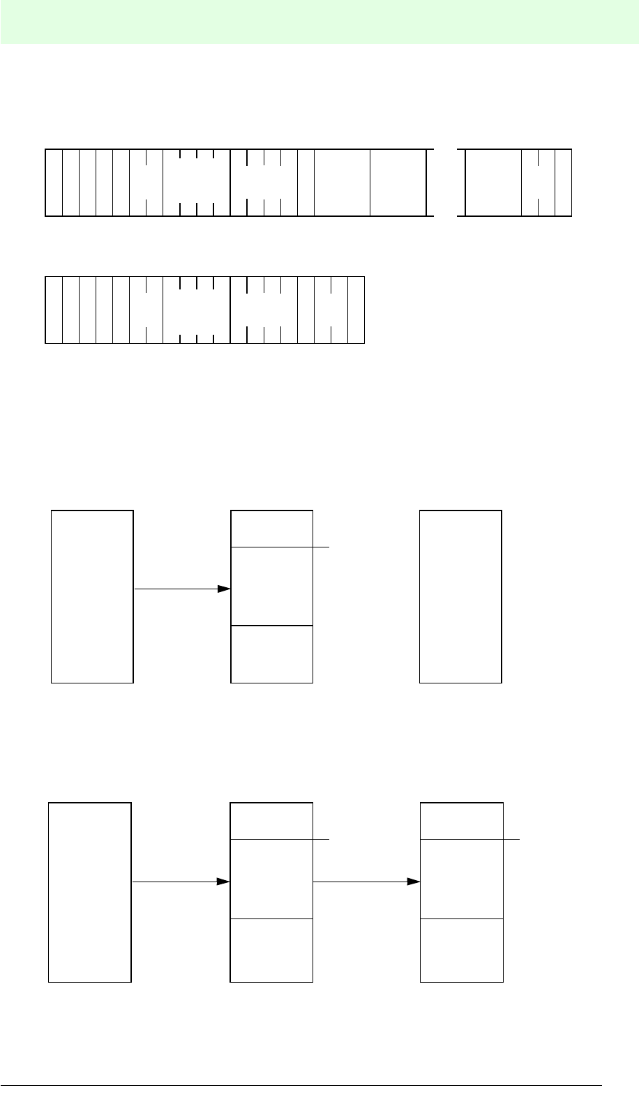
IDENT-M System V
Commands
Date of issue 03.05.2001
155
Subject to reasonable modifications due to technical advances. Copyright Pepperl+Fuchs, Printed in Germany
Pepperl+Fuchs Group • Tel.: Germany (06 21) 7 76-0 • USA (330) 4 25 35 55 • Singapore 7 79 90 91 • Internet http://www.pepperl-fuchs.com
Writing Data into the Control Interface Unit (Transmission Code: 25h)
Command
End message
When writing data into the MVI-D2-2HRX special area, the command writes data into
the system area regardless of whether the number of the read/write head command
(ANT) is 0 or 1.
Data Transmission
Writing into the system memory of the control interface unit
Along with the command “write and check data” from the MVI-D2-2HRX to the data
carrier, this command can transmit a multitude of data from the host controller to the
data carrier.
(1) Write data to an MVI-D2-2HRX (max. 512 bytes).
(2) Write and check data from the MVI-D2-2HRX to the data carrier (max. 7552 or 30976 bytes).
S
A
T
A
T
N
:: ?
Start address
transm. source
(MVI-D2-
2HRX)
Number
of bytes
D
D
C
2 5 Data 1 Data 2 Data n
S
(H)
C
S
(L)
CR
C
S
A
T
A
T
N
:: ?
Start address
transm. source
(MVI-D2-
2HRX)
Number
of bytes
D
D
C
2 5
S
(H)
C
S
(L)
CR
C
Selected
number of
bytes (max.
512
bytes)
Start of selected
address
Host controller
Memory of MVI-D2-2HRX
(system memory)
Memory of
data carrier
Setting data
Selected
number of
bytes (7552
or max.
30976
Start of selected
address
Selected
number of
bytes (7552
or max.
30976
Start of selected
address
Host controller
Memory of MVI-D2-2HRX
(data carrier buffer)
Memory of
data carrier
2)1)
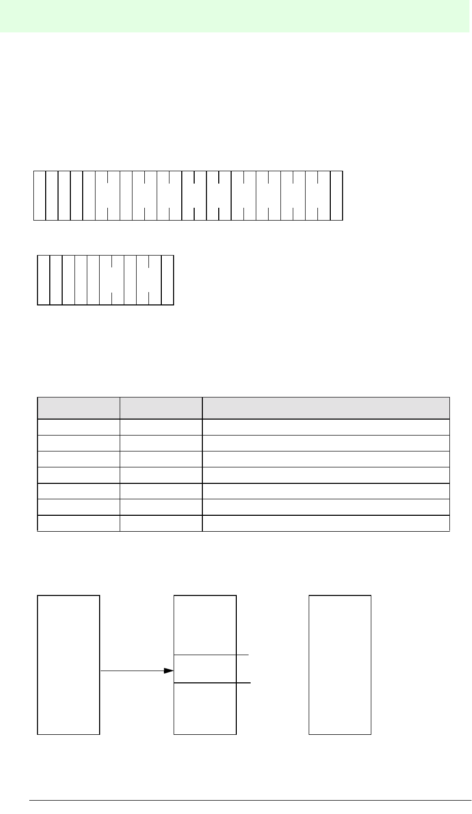
IDENT-M System V
Commands
Date of issue 03.05.2001
156
Subject to reasonable modifications due to technical advances. Copyright Pepperl+Fuchs, Printed in Germany
Pepperl+Fuchs Group • Tel.: Germany (06 21) 7 76-0 • USA (330) 4 25 35 55 • Singapore 7 79 90 91 • Internet http://www.pepperl-fuchs.com
Setting the Current Time (Transmission Code: 26h)
This command transmits date and time (year, month, day, weekday, hour, minute and
second) from the host controller to the clock integrated in the MVI-D2-2HRX. With this
command the data in the MVI-D2-2HRX system memory also changes (address
A000h to A006h, 7 bytes).
Command
End message
This command writes the time into the same MVI-D2-2HRX special area regardless
of whether the number of the read/write head command (ANT) is 0 or 1.
Both data formats, hexadecimal: h and JIS: j are available for the data code (DCD).
Data Value:
Data Transmission
Position Value (BCD) Notes
Year 00 ... 99 Without digits indicating the century
Month 01 ... 12
Day 01 ... 31
Weekday 00 ... 06 Sun - Sat = 00 - 06
Hour 00 ... 23
Minute 00 ... 59
Second 00 ... 59
(H) (L)
Weekd
S
(H)
C
S
(L)
C
2?
S
A
T
A
T
N
:: R
C
6
D
D
C
(H) (L)
Year
(H) (L)
Second
(H) (L)
Month
(H) (L)
Day
(H) (L)
Minute
(H) (L)
Hour
S
(H)
C
S
(L)
C
1?
S
A
T
A
T
N
:: R
C
6
D
D
C
time entry
(7 bytes)
A000h
Host controller
Memory of MVI-D2-2HRX
(system memory)
Memory of
data carrier
A006h
Time
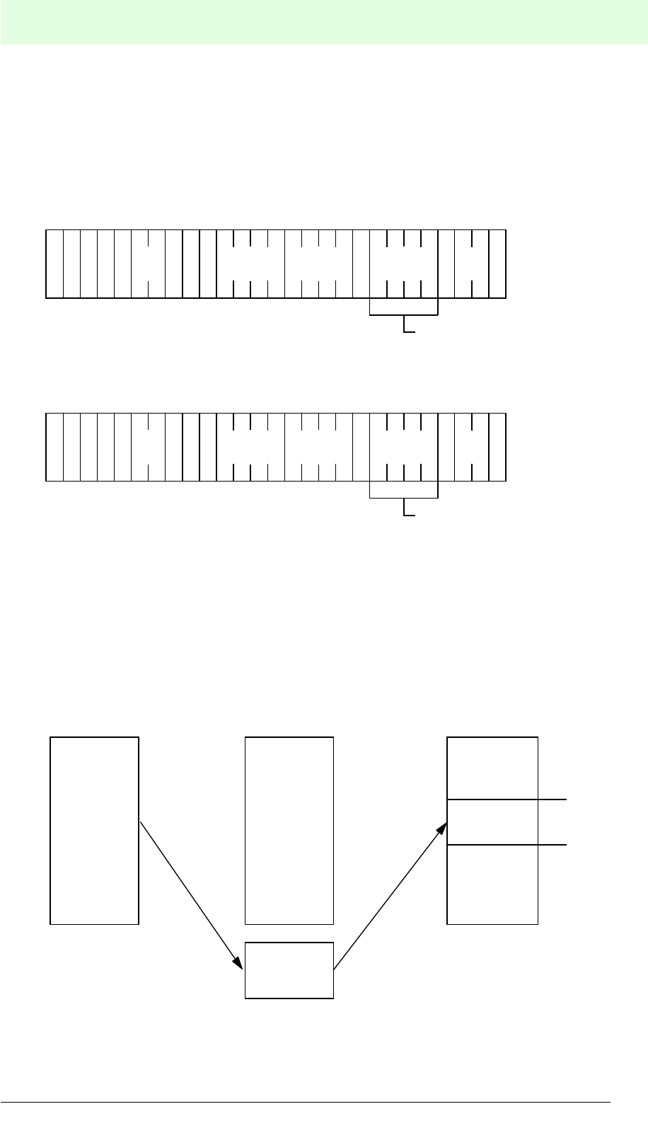
IDENT-M System V
Commands
Date of issue 03.05.2001
157
Subject to reasonable modifications due to technical advances. Copyright Pepperl+Fuchs, Printed in Germany
Pepperl+Fuchs Group • Tel.: Germany (06 21) 7 76-0 • USA (330) 4 25 35 55 • Singapore 7 79 90 91 • Internet http://www.pepperl-fuchs.com
Clear (Transmission Code: 30h)
This command writes the same data from a specific starting address to the memory
of the data carrier with a specified number of bytes. The maximum number of erasable
bytes is 7552 or 30976.
Command
End message
1) In the case of the occasional execution system, command stay system, or read/write head
scan system, this command sets “*” into the command memory. In this setting the command
also stores “*” in the end message.
2) Both data formats, hexadecimal: h and JIS: j are available for the data code (DCD).
Hexadecimal: 00 to FF
JIS: One digit JIS code
Data Transmission
Note: When executing the clear command, the data carrier buffer of the MVI-D2-
2HRX is not changed.
1) 2)
S
A
T
A
T
N
:: ?
Registration
P
O
R
Attribute
Start
address
Number
of bytes
ID code
D
D
C
S
(H)
C
S
(L)
CR
C
Omit when attribute is “without
ID code allocation”.
3 0
Clear data
1
)
2
)
S
A
T
A
T
N
:: #
Registration
P
O
R
Attribute
Start
address
Number
of bytes
ID code
D
D
C
S
(H)
C
S
(L)
CR
C
Omit, when attribute is “without
ID code return”.
3 0
Clear data
Clear data
(1 byte)
Host controller
Memory of MVI-D2-2HRX
(data carrier buffer)
Memory of
data carrier
Specific
number of
bytes
Special area
for clearing
(1 byte)
Start address
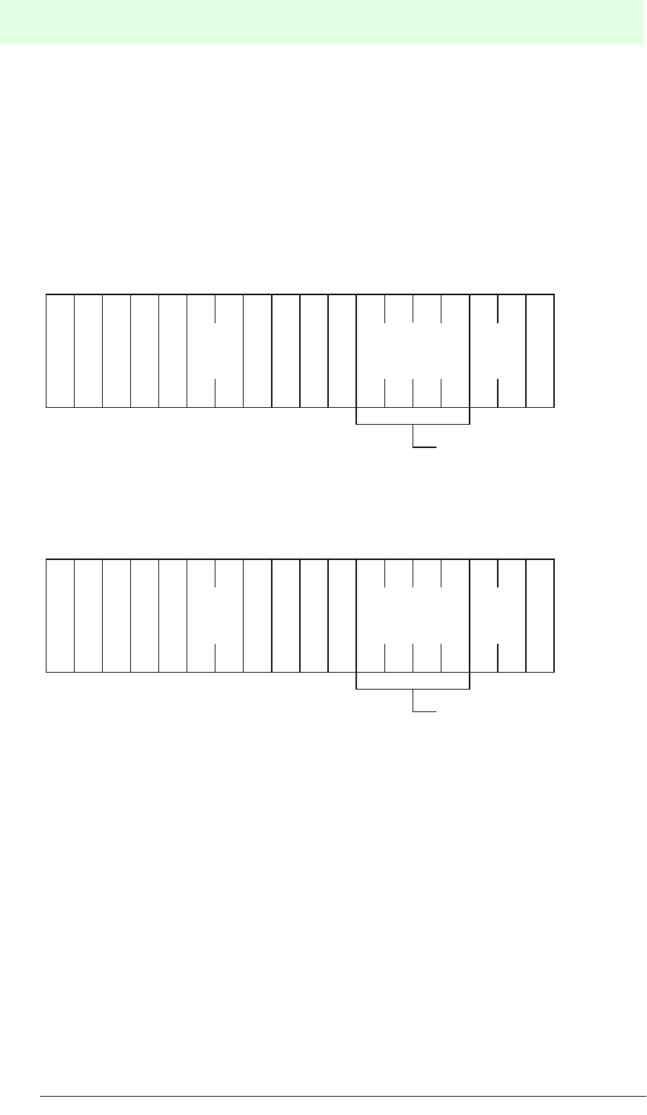
IDENT-M System V
Commands
Date of issue 03.05.2001
158
Subject to reasonable modifications due to technical advances. Copyright Pepperl+Fuchs, Printed in Germany
Pepperl+Fuchs Group • Tel.: Germany (06 21) 7 76-0 • USA (330) 4 25 35 55 • Singapore 7 79 90 91 • Internet http://www.pepperl-fuchs.com
Initialise Data Carrier (Transmission Code: 31h)
This command initialises the entire memory area of the data carrier.
• Data area: 00h, system area: initial values.
• This command also clears the setting of the system memory protection in the data
carrier.
Command
End message
1) In the occasional execution system, command stay system, or read/write head scan system,
this command sets “*” into the command memory. In this setting the command also stores “*”
in the end message.
2) Data code (DCD) must be set for the ID code (hexadecimal: h, JIS: j).
?
S
(H)
C
S
(L)
CR
C
: :
S
A
T
A
T
N31
Registration
Attribute
D
D
CID code
1) 2)
P
O
R
Omit when attribute is “without
ID code allocation”.
#
S
(H)
C
S
(L)
CR
C
: :
S
A
T
A
T
N31
Registration
Attribute
D
D
CID code
1) 2)
P
O
R
Omit, when attribute is “without
ID code return”.

IDENT-M System V
Commands
Date of issue 03.05.2001
159
Subject to reasonable modifications due to technical advances. Copyright Pepperl+Fuchs, Printed in Germany
Pepperl+Fuchs Group • Tel.: Germany (06 21) 7 76-0 • USA (330) 4 25 35 55 • Singapore 7 79 90 91 • Internet http://www.pepperl-fuchs.com
Clearing the Data of the Control Interface Unit (Transmission Code: 35h)
This command writes the same data from a specific starting address of the MVI-D2-
2HRX memory (data carrier buffer and system memory) with a specific number of
bytes. The maximum number of erasable bytes is 7552 or 30976.
Command
End message
• When clearing the MVI-D2-2HRX system area, this command clears the same
area regardless of whether the number of the read/write head command (ANT) is
0 or 1.
• Both data formats, hexadecimal: h and JIS: j are available for the data code
(DCD).
• Clear data
hexadecimal: 00 to FF
JIS: One digit JIS code
Data Transmission
Clear data
S
A
T
A
T
N
:: ?
Registration
P
O
R
Attribute
Start
address
Number
of bytes
D
D
C
S
(H)
C
S
(L)
CR
C
3 5
S
A
T
A
T
N
:: ?
Registration
P
O
R
Attribute
Start
address
Number
of bytes
D
D
C
S
(H)
C
S
(L)
CR
C
3 5
Clear data
(1 byte)
Host controller Memory of MVI-D2-2HRX
Memory of
data carrier
Selected
number of
bytes
Specific starting
address

IDENT-M System V
Commands
Date of issue 03.05.2001
160
Subject to reasonable modifications due to technical advances. Copyright Pepperl+Fuchs, Printed in Germany
Pepperl+Fuchs Group • Tel.: Germany (06 21) 7 76-0 • USA (330) 4 25 35 55 • Singapore 7 79 90 91 • Internet http://www.pepperl-fuchs.com
Initialisation of MVI-D2-2HRX (Transmission Code: 36h)
This command initialises the data of the entire MVI-D2-2HRX system memory. It also
resets the transmission time protocol, the number of the transmission protocol as well
as the error protocol.
Command
End message
The MVI-D2-2HRX system area is initialised regardless of whether the number of the read/write
head command (ANT) is 0, 1 or *.
S
A
T
A
T
N
:: ? 3 6
S
(H)
C
S
(L)
CR
C
S
A
T
A
T
N
:: # 3 6
S
(H)
C
S
(L)
CR
C

IDENT-M System V
Commands
Date of issue 03.05.2001
161
Subject to reasonable modifications due to technical advances. Copyright Pepperl+Fuchs, Printed in Germany
Pepperl+Fuchs Group • Tel.: Germany (06 21) 7 76-0 • USA (330) 4 25 35 55 • Singapore 7 79 90 91 • Internet http://www.pepperl-fuchs.com
Clear Protocol (Transmission Code: 37h)
This command clears the transmission time protocol, the number of the transmission
protocol as well as the error protocol of the MVI-D2-2HRX system memory.
• Selectable initialisation area of the transmission time protocol, the number of the
transmission protocol or the error protocol.
• Selectable areas (for each read/write head)
1. Transmission time protocol:
Starting address 90A0h, 20 bytes
2. Number of the transmission protocol:
Starting address 90C0h, 8 bytes
3. Error protocol:
Starting address 9100h, 3202 bytes
Command
1) Select area to initialise
0 = Transmission time protocol
1 = Number of transmission protocol
2 = Error protocol
End message
S
A
T
A
T
N
:: ?37
S
(H)
C
S
(L)
CR
C
Area
1)
S
A
T
A
T
N
:: #37
S
(H)
C
S
(L)
CR
C

IDENT-M System V
Commands
Date of issue 03.05.2001
162
Subject to reasonable modifications due to technical advances. Copyright Pepperl+Fuchs, Printed in Germany
Pepperl+Fuchs Group • Tel.: Germany (06 21) 7 76-0 • USA (330) 4 25 35 55 • Singapore 7 79 90 91 • Internet http://www.pepperl-fuchs.com
Copy
Copy Data between Different Read/Write Heads
(Transmission Code: 40h)
Copy and Check Data between Different Read/Write Heads
(Transmission Code: 41h)
This command reads data within a specific memory area of the data carrier (copy
source), which is located in the communication area of the read/write head and writes
into the memory of the data carrier (copy destination) which is located in the
communication area of the other read/write head.
Specify the number of the copy source's read/write head in the command as number
of the read/write head (ANT). (ANT = 0 corresponds to copying data from read/write
head 0 to read/write head 1. ANT = 1 corresponds to copying data from read/write
head 1 to read/write head 0.)
The maximum number of bytes that can be copied is 7552 or 30976.
Note: This copy command cannot be used when the read/write head scan system is
in normal operation.
Command
End message
1) In the case of the occasional execution system or command stay system, this command sets
“*” into the command memory. In this setting the command stores “*” in the end message.
2) Set the protection setting for the copy destination in the data carrier (PRO).
3) The data code (DCD) should be set for the ID code (hexadecimal: h, JIS: j).
4) When the attribute is set to “ID code allocated function/non-function”, the ID code of the copy
destination, the data carrier, is to be set in this area. When the attribute is set to “without ID
code allocation”, omit this setting.
5) When the attribute is set to “ID code with acknowledgement”, the ID code of the copy destina-
tion, i.e. the data carrier, is returned to this area. When the attribute is set to “without ID code
allocation”, this area is omitted.
Transmission
code
S
A
T
A
T
N
:: #
Registration
P
O
R
Attribute
Start address
(source)
Number
of bytes
ID codeStart address
(destination)
D
D
C
S
(H)
C
S
(L)
CR
C
1) 4)3)2)
Transmission
code
S
A
T
A
T
N
:: #
Registration
P
O
R
Attribute
Start address
(source)
Number
of bytes
ID codeStart address
(destination)
D
D
C
S
(H)
C
S
(L)
CR
C
1) 5)3)2)
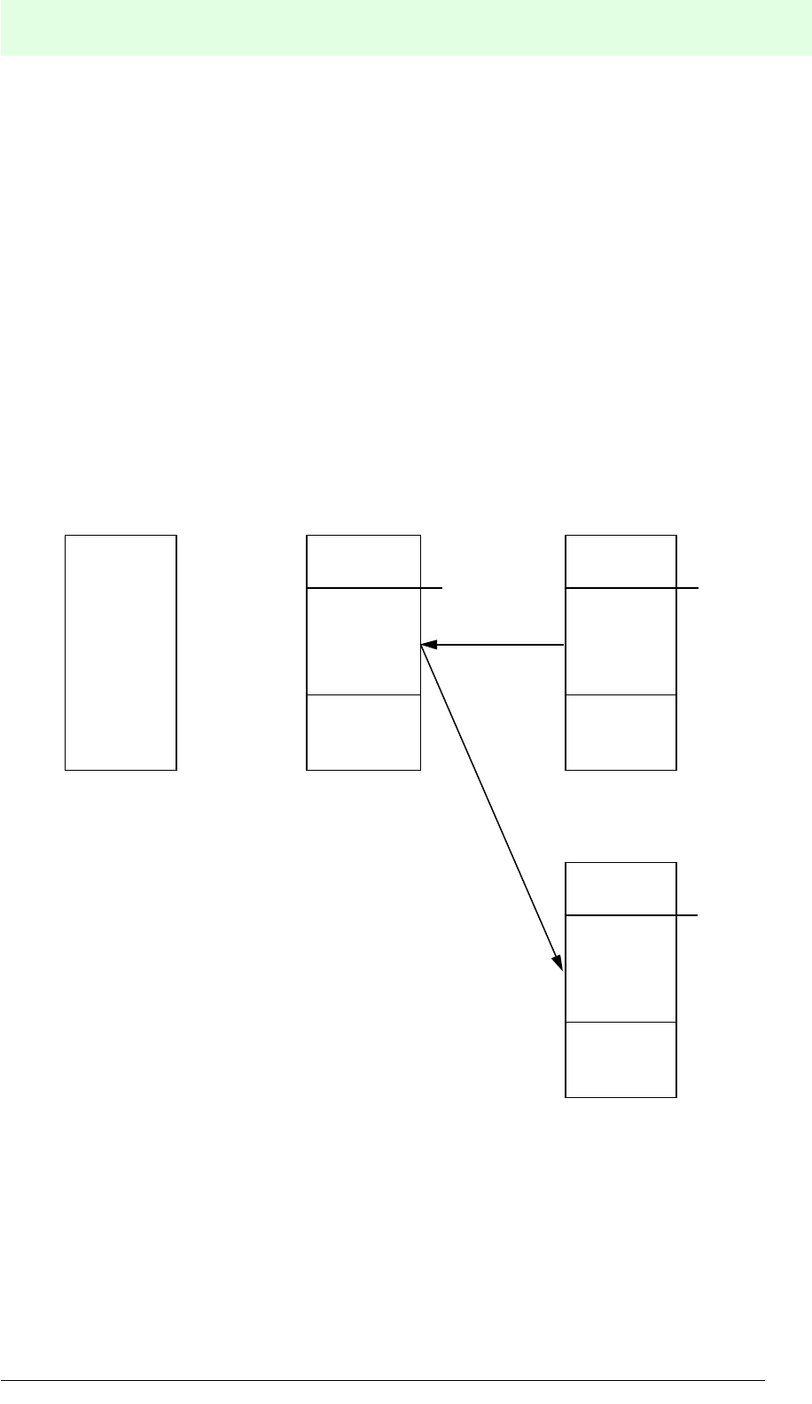
IDENT-M System V
Commands
Date of issue 03.05.2001
163
Subject to reasonable modifications due to technical advances. Copyright Pepperl+Fuchs, Printed in Germany
Pepperl+Fuchs Group • Tel.: Germany (06 21) 7 76-0 • USA (330) 4 25 35 55 • Singapore 7 79 90 91 • Internet http://www.pepperl-fuchs.com
Writing start method of copy commands
1. Occasional execution system: Start writing after end of reading (automatic writing
of the MVI-D2-2HRX).
2. Command stay system or command register system: Writing starts with the
trigger input of the writing read/write head.
In case data is copied in the occasional execution system and by the instruction of the
host controller.
Read: Read and check data from the data carrier to the MVI-D2-2HRX.
Write: Write and check data from the MVI-D2-2HRX to the data carrier.
Data Transmission
Copy and check data between read/write heads.
Host controller
Memory of MVI-D2-2HRX
(data carrier buffer)
Memory of data carrier in
front of read/write head
containing the source data
Selected
number of
bytes
Start
address Selected
number of
bytes
Start
address
Start
address
Memory of data carrier in
front of read/write head for
the target data
Selected
number of
bytes
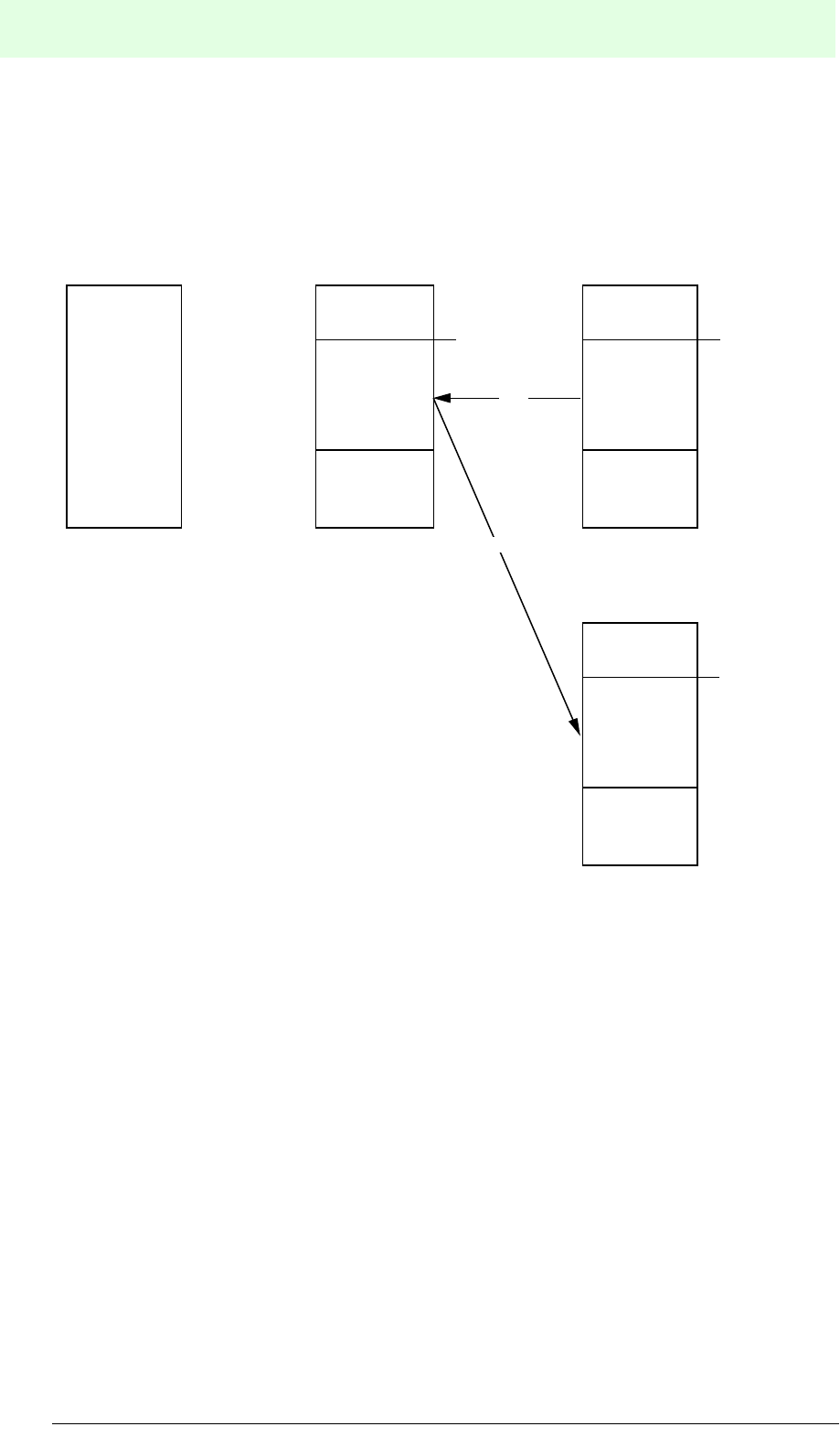
IDENT-M System V
Commands
Date of issue 03.05.2001
164
Subject to reasonable modifications due to technical advances. Copyright Pepperl+Fuchs, Printed in Germany
Pepperl+Fuchs Group • Tel.: Germany (06 21) 7 76-0 • USA (330) 4 25 35 55 • Singapore 7 79 90 91 • Internet http://www.pepperl-fuchs.com
Data Transmission
When copying and checking data with the read/write head in the occasional execution
system.
(1) Read: Read and check data from the data carrier to the MVI-D2-2HRX
(2) Write: Write and check data from the MVI-D2-2HRX to the data carrier.
Host controller
Memory of MVI-D2-2HRX
(data carrier buffer)
Memory of data carrier in
front of read/write head
containing the source data
Selected
number of
bytes
Start
address Selected
number of
bytes
Start
address
Memory of data carrier in
front of read/write head for
the target data
Selected
number of
bytes
Start
address
(1)
(2)
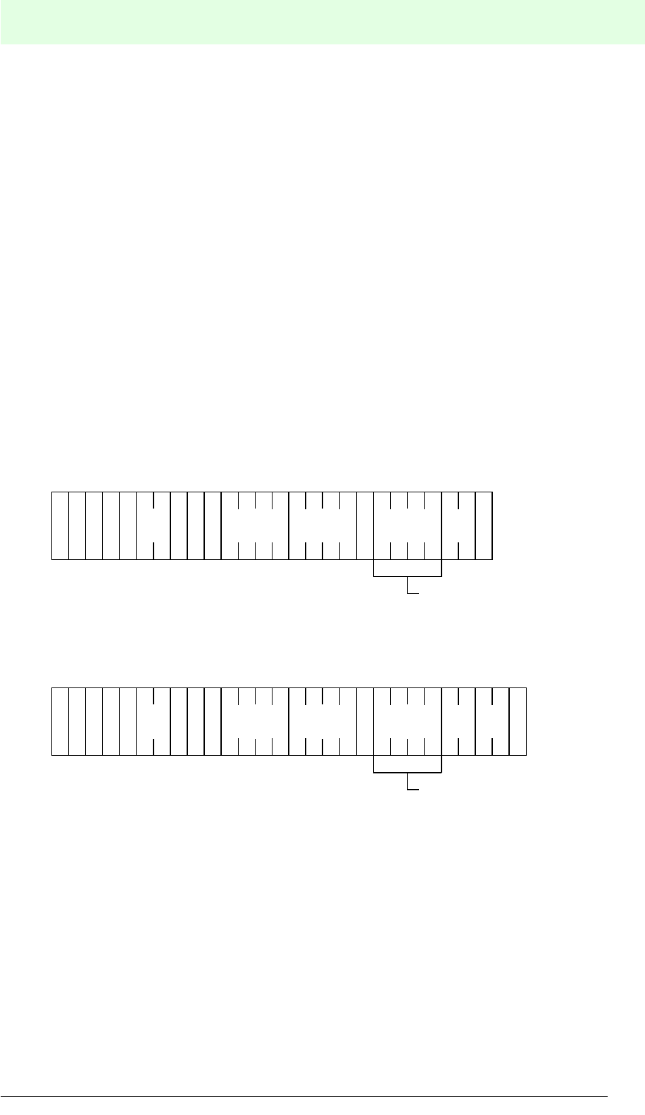
IDENT-M System V
Commands
Date of issue 03.05.2001
165
Subject to reasonable modifications due to technical advances. Copyright Pepperl+Fuchs, Printed in Germany
Pepperl+Fuchs Group • Tel.: Germany (06 21) 7 76-0 • USA (330) 4 25 35 55 • Singapore 7 79 90 91 • Internet http://www.pepperl-fuchs.com
Diagnostic Commands
Five types of diagnostic functions are available in accordance with the contents of the
settings and the messages.
1. Self-diagnosis of data carrier (50h)
2. RAM check (52h), block check (60h)
3. ROM check (51h)
4. Battery life check of data carrier (53h)
5. Self-diagnosis of MVI-D2-2HRX (55h)
The values in brackets constitute the transmission codes.
Self-Diagnosis of the Data Carrier (Transmission Code: 50h)
The data carrier diagnoses independently whether CPU, ROM, RAM and battery life
are normal.
• The setting range in this command is the RAM check range. When the range is
not set, the command performs a ROM check and a battery check.
• The maximum number of bytes that can be diagnosed is 7552 or 30976.
Command
End message (When diagnostic result is normal)
1) In the case of the occasional execution system or command stay system, this command sets
“*” into the command memory. In this setting the command stores “*” in the end message.
When the number of bytes is 0000h , this command does not perform a RAM check.
The diagnostic command does only perform the ROM check and the battery life
check.
• The command checks the whole area (data memory and system memory), when
both starting addresses and the number of bytes are set to “****”.
• When the number of bytes is set to “****” this command checks the whole area of
the starting address.
• When an error is found using the diagnostic, the MVI-D2-2HRX sends an error
message including the test of the battery service life.
S
A
T
A
T
N
:: #
Registration
*
Attribute
Start
address
Number
of bytes
ID code
D
D
C
S
(H)
C
S
(L)
CR
C
1)
5 0
Omit when attribute is “without
ID code allocation”.
S
A
T
A
T
N
:: #
Registration
*
Attribute
Start
address
Number
of bytes
ID code
D
D
C
S
(H)
C
S
(L)
CR
C
1)
5 0
Omit when attribute is “without
ID code allocation”.
Battery
state (1
byte)
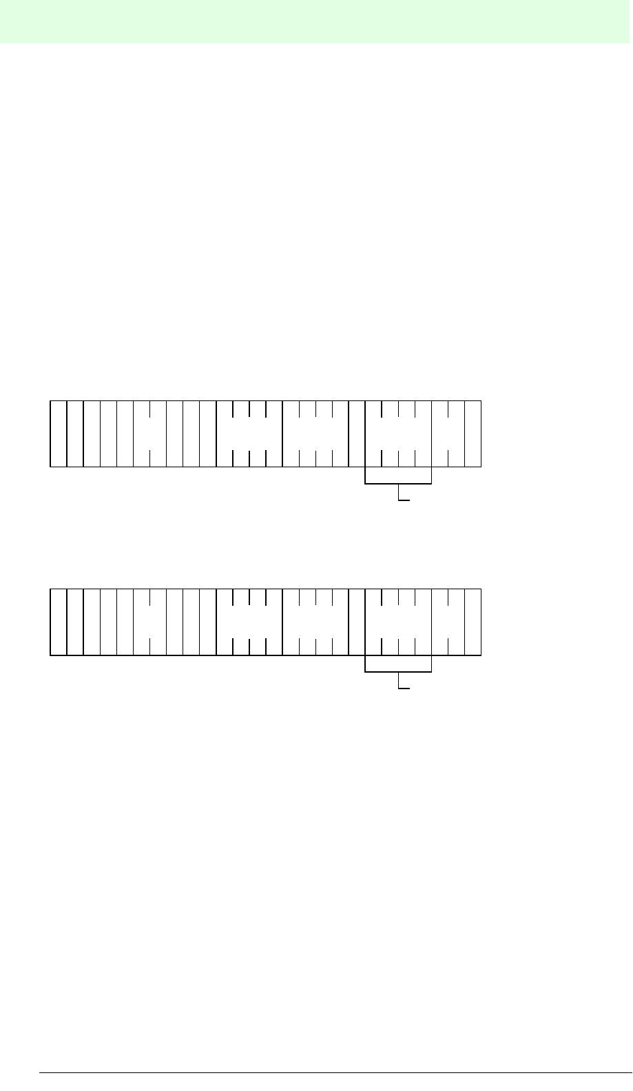
IDENT-M System V
Commands
Date of issue 03.05.2001
166
Subject to reasonable modifications due to technical advances. Copyright Pepperl+Fuchs, Printed in Germany
Pepperl+Fuchs Group • Tel.: Germany (06 21) 7 76-0 • USA (330) 4 25 35 55 • Singapore 7 79 90 91 • Internet http://www.pepperl-fuchs.com
RAM Check (Transmission Code: 52h)
Block Check (Transmission Code: 60h)
• RAM check: Checks whether the RAM in the data carrier works normally.
• Block check: Checks whether data written in the data carrier was not changed by
anything other than write instructions.
• The maximum number of bytes that can be diagnosed is 7552 or 30976.
• The command checks the whole area (data memory and system memory), when
both starting addresses and the number of bytes are set to “****”.
• When an error is found in the diagnosis, the data carrier returns an error
message.
Command
End message (when the data is normal)
1) In the case of the occasional execution system or command stay system, this command sets
“*” into the command memory. In this setting the command stores “*” in the end message.
S
A
T
A
T
N
:: ?
Transmission
code
Registration
*
Attribute
Start
address
Number
of bytes
ID code
D
D
C
S
(H)
C
S
(L)
CR
C
1)
Omit when attribute is
“without ID code allocation”.
S
A
T
A
T
N
:: #
Transmission
code
Registration
*
Attribute
Start
address
Number
of bytes
ID code
D
D
C
S
(H)
C
S
(L)
CR
C
1)
Omit when attribute is
“without ID code allocation”.
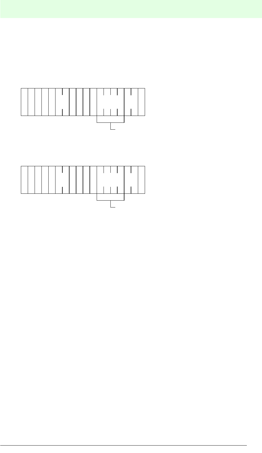
IDENT-M System V
Commands
Date of issue 03.05.2001
167
Subject to reasonable modifications due to technical advances. Copyright Pepperl+Fuchs, Printed in Germany
Pepperl+Fuchs Group • Tel.: Germany (06 21) 7 76-0 • USA (330) 4 25 35 55 • Singapore 7 79 90 91 • Internet http://www.pepperl-fuchs.com
ROM Check (Transmission Code: 51h)
This command diagnoses whether the ROM in the data carrier functions properly.
Command
End message (when diagnostic result is normal)
1) In the case of the occasional execution system or command stay system, this command sets
“*” into the command memory. In this setting the command stores “*” in the end message.
When an error is found using the diagnostic, the data carrier returns an error
message.
S
A
T
A
T
N
:: ?
Registration
*
Attribute
ID code
D
D
C
S
(H)
C
S
(L)
CR
C
1)
Omit when attribute is
“without ID code allocation”.
5 1
S
A
T
A
T
N
:: #
Registration
*
Attribute
ID code
D
D
C
S
(H)
C
S
(L)
CR
C
1)
Omit when attribute is
“without ID code allocation”.
5 1
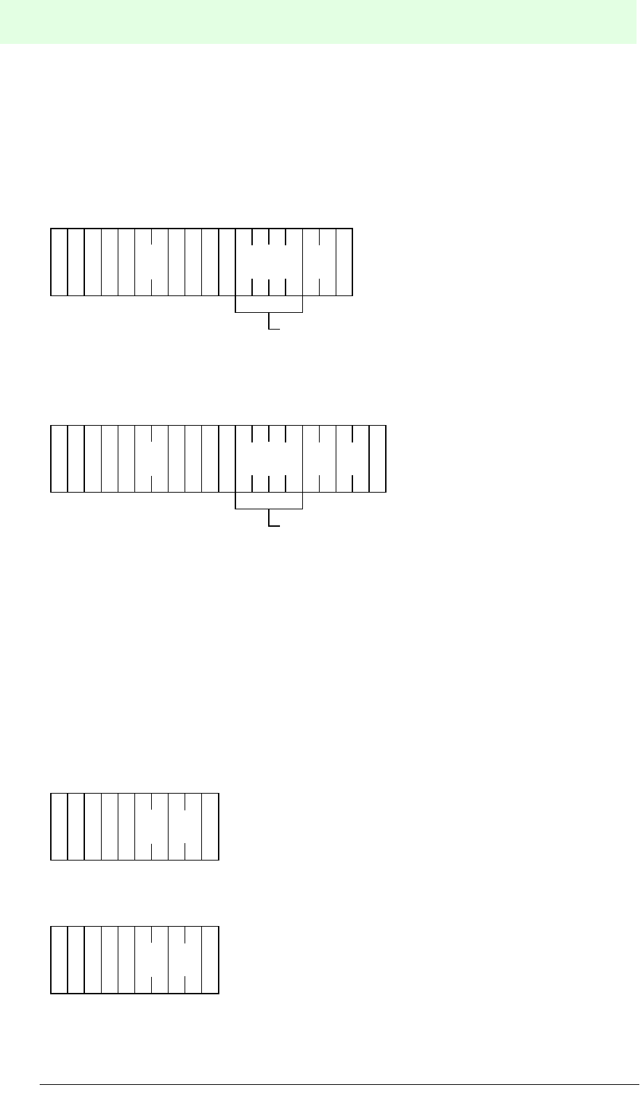
IDENT-M System V
Commands
Date of issue 03.05.2001
168
Subject to reasonable modifications due to technical advances. Copyright Pepperl+Fuchs, Printed in Germany
Pepperl+Fuchs Group • Tel.: Germany (06 21) 7 76-0 • USA (330) 4 25 35 55 • Singapore 7 79 90 91 • Internet http://www.pepperl-fuchs.com
Data Carrier's Battery Life Check)
(Transmission Code: 53h)
This command checks the life span of the battery in the data carrier. The command
diagnoses the battery voltage and the battery service life for test purposes.
Command
End message (when diagnostic result is normal)
1) In the case of the occasional execution system or command stay system, this command sets
“*” into the command memory. In this setting the command stores “*” in the end message.
When an error is found using the diagnostic, the data carrier sends an error message
including the value of the battery service life.
Self-Diagnosis of the MVI-D2-2HRX (Transmission Code: 55h)
This command checks whether ROM and RAM function properly and whether the
batteries still have enough voltage.
Command
End message (when diagnostic result is normal)
When an error is found using the diagnostic, the MVI-D2-2HRX sends an error
message.
S
A
T
A
T
N
:: #
Registration
*
Attribute
ID code
D
D
C
S
(H)
C
S
(L)
CR
C
1)
Omit when attribute is
“without ID code allocation”.
5 3
S
A
T
A
T
N
:: #
Registration
*
Attribute
ID code
D
D
C
S
(H)
C
S
(L)
CR
C
1)
Omit when attribute is
“without ID code allocation”.
5 3 Battery
state (1
byte)
S
A
T
A
T
N
:: ?
S
(H)
C
S
(L)
CR
C
5 5
1) 1) This command is available, regardless of whether the
read/write head (ANT) is set to 0, 1 or *.
S
A
T
A
T
N
:: ?
S
(H)
C
S
(L)
CR
C
5 5
IDENT-M System V
Commands
Date of issue 03.05.2001
169
Subject to reasonable modifications due to technical advances. Copyright Pepperl+Fuchs, Printed in Germany
Pepperl+Fuchs Group • Tel.: Germany (06 21) 7 76-0 • USA (330) 4 25 35 55 • Singapore 7 79 90 91 • Internet http://www.pepperl-fuchs.com
Other Functions
Reset (Transmission Code: 70h)
• Stops the current execution of a command.
• This command clears the error condition of the MVI-D2-2HRX (switches OFF the
error indication LED).
Command
End message
Result Request (Transmission Code: 71h)
This command requests the function result to be sent (end message or error
message) from the response request system.
Message contents
1. When the MVI-D2-2HRX has ended the instruction execution, it sends the end
message of the command.
2. When the MVI-D2-2HRX still executes the command, it sends the end message
of the “result request”.
Command
End message (when the MVI-D2-2HRX still operates)
S
A
T
A
T
N
:: ?
S
(H)
C
S
(L)
CR
C
7 0
ANT Reset of the read/write head
00
11
* 0, 1 (both)
S
A
T
A
T
N
:: ?
S
(H)
C
S
(L)
CR
C
7 0
S
A
T
A
T
N
:: ?
S
(H)
C
S
(L)
CR
C
7 1
S
A
T
A
T
N
:: #
S
(H)
C
S
(L)
CR
C
7 1
IDENT-M System V
Commands
Date of issue 03.05.2001
170
Subject to reasonable modifications due to technical advances. Copyright Pepperl+Fuchs, Printed in Germany
Pepperl+Fuchs Group • Tel.: Germany (06 21) 7 76-0 • USA (330) 4 25 35 55 • Singapore 7 79 90 91 • Internet http://www.pepperl-fuchs.com
Output Instruction (Transmission Code: 72h)
This command switches outputs 0 to 3 of the MVI-D2-2HRX ON or OFF. This
command is available for the function regardless of whether the setting of the read/
write head (ANT) is 0, 1 or *.
Command
End message
Read Status (Transmission Code: 73h)
This command reads the status of the MVI-D2-2HRX.
Command
End message
S
A
T
A
T
N
::
?
S
(H)
C
S
(L)
CR
C
7 2
Output 2
Output 3
Output 4
Set outputs: 0 = OFF; 1 = ON
Output 1
S
A
T
A
T
N
:: #
S
(H)
C
S
(L)
CR
C
7 2
S
A
T
A
T
N
:: #
S
(H)
C
S
(L)
CR
C
7 3
Status
S
A
T
A
T
N
:: ?
S
(H)
C
S
(L)
CR
C
7 3
Status Description
0 Wait for trigger input
1 Wait for command
2 Data carrier access
3 Data carrier error
4
Wait for end of operation of the opposite read/write
head (when copying data between the read/write
heads)
5 Search for a data carrier
6Another station accesses the data carrier (read/write
head scan function)
IDENT-M System V
Commands
Date of issue 03.05.2001
171
Subject to reasonable modifications due to technical advances. Copyright Pepperl+Fuchs, Printed in Germany
Pepperl+Fuchs Group • Tel.: Germany (06 21) 7 76-0 • USA (330) 4 25 35 55 • Singapore 7 79 90 91 • Internet http://www.pepperl-fuchs.com
Stop Function (Transmission Code: 74h)
• This command stops the transmission function in the MVI-D2-2HRX using the
command register system (startup system: A008h= 2). In this case, the MVI-D2-
2HRX does not execute the stored function by switching ON the trigger input.
(Instruction for the stored function: 9010h= 0)
• This command inevitably stops the transmission function during the read/write
head scan.
• This command is only available when “*” is set as read/write head (ANT).
Command
End message
Command when Trigger Input is ON (Transmission Code: 75h)
• When the trigger input is switched ON, the command executes the command
stored under the storage number (command register system: A008h=2).
• This command sets the memory contents of the address 9010h in the system area
of the respective data carrier.
Command
End message
End message of the stored command.
S
A
T
A
T
N
:: ?
S
(H)
C
S
(L)
CR
C
7 4
S
A
T
A
T
N
:: #
S
(H)
C
S
(L)
CR
C
7 4
S
A
T
A
T
N
:: #
S
(H)
C
S
(L)
CR
C
7 5
Register No
Storage number of the command, when the trigger
input is ON.

IDENT-M System V
Commands
Date of issue 03.05.2001
172
Subject to reasonable modifications due to technical advances. Copyright Pepperl+Fuchs, Printed in Germany
Pepperl+Fuchs Group • Tel.: Germany (06 21) 7 76-0 • USA (330) 4 25 35 55 • Singapore 7 79 90 91 • Internet http://www.pepperl-fuchs.com
Start of the Next Command (Transmission Code: 76h)
This command enables the stored command to be executed when the trigger input in
the command register system is ON (Startup system: A008h= 2). (The storage
number should be executed after the transmission function, which is triggered by the
command to start the function (transmission code: 75h)).
Conditions for executing the command:
1. Executes the stored function number at the function start (transmission
code: 75h).
2. The MVI-D2-2HRX trigger input is set to ON.
Command
End message
End message of the stored command.
Re-execution (Transmission Code: 77h)
This command initiates the re-execution of the transmission function by the command
register system (startup system: A008h= 2). The command is used when the message
of the MVI-D2-2HRX contains a mistake. By means of this command the MVI-D2-
2HRX executes the previously executed command.
Command
End message
End message of the stored command.
S
A
T
A
T
N
:: ?
S
(H)
C
S
(L)
CR
C
7 6
Register No
S
A
T
A
T
N
:: ?
S
(H)
C
S
(L)
CR
C
7 7

IDENT-M System V
Commands
Date of issue 03.05.2001
173
Subject to reasonable modifications due to technical advances. Copyright Pepperl+Fuchs, Printed in Germany
Pepperl+Fuchs Group • Tel.: Germany (06 21) 7 76-0 • USA (330) 4 25 35 55 • Singapore 7 79 90 91 • Internet http://www.pepperl-fuchs.com
9.4.5 Example for Application of the “Single Read” Mode
Transmission with a Stopped Data Carrier
(Communication startup system: Command stay system)
This method is the most reliable transmission method, since the position of the data
carrier in relation to the read/write head is fixed.
1. The commands from the host controller to the MVI-D2-2HRX are stored in
advance.
2. The data carrier must be mounted on the pallet so that it can be transported with
the conveyor device.
3. When the pallet reaches the calculated position, the pallet recognition switch is
activated and switches the MVI-D2-2HRX trigger input ON. The pallet is stopped
by a stopper.
4. With the pallet arrival signal, the read/write head starts communication with the
data carrier.
The optimum condition is when the data carrier and the read/write head face each
other directly in the stop position.
If the pallet is stopped only by a stopper, it may move backwards during the
transmission procedure, and the data carrier on the pallet may come outside the
transmission area of the read/write head. Therefore, a stopper is required in order to
prevent the pallet from moving backwards.
Transmission with a Moving Data Carrier
(Communication startup system, command stay system).
This system is suitable for mounting parts, which are moving on the belt conveyor.
The system shortens the clock time.
1. The transmission commands from the host controller to the MVI-D2-2HRX are
stored in advance.
2. The data carrier must be mounted on the pallet so that it can be transported with
the conveyor device.
3. Install proximity switches just before each arrival position at the work place. After
the proximity switch has responded, switch the trigger input ON (the data carrier
should be within the transmission area of the read/write head).
4. On arrival of the proximity switch signal, the read/write head starts communication
with the data carrier.
5. Before the pallet reaches the working station, the read/write head should already
have finished exchanging data with the data carrier.
IDENT-M System V
Commands
Date of issue 03.05.2001
174
Subject to reasonable modifications due to technical advances. Copyright Pepperl+Fuchs, Printed in Germany
Pepperl+Fuchs Group • Tel.: Germany (06 21) 7 76-0 • USA (330) 4 25 35 55 • Singapore 7 79 90 91 • Internet http://www.pepperl-fuchs.com
The transmission should be completed before the data carrier comes out of reach of
the read/write head's transmission area. In order to provide sufficient tolerance to
complete the transmission, the relation between the data carrier movement and the
required transmission time to the data carrier (including retry time interval in the case
of a transmission error) must be taken into account. Then the time-limit for the
transmission has to be set in the memory address 9000hof the MVI-D2-2HRX.
(Example for transmission with a moving data carrier)
1. The proximity switch detects the pallet (data carrier), which passes position A
(within the transmission area) and switches the trigger input ON in order to start
the transmission.
2. The read/write head ends the transmission before the pallet passes position B.
3. Place the working station after position B.
Transmission area
Moving direction
Target
Proximity switch
Pallet
AB
Read/write head
Data carrier

IDENT-M System V
Commands
Date of issue 03.05.2001
175
Subject to reasonable modifications due to technical advances. Copyright Pepperl+Fuchs, Printed in Germany
Pepperl+Fuchs Group • Tel.: Germany (06 21) 7 76-0 • USA (330) 4 25 35 55 • Singapore 7 79 90 91 • Internet http://www.pepperl-fuchs.com
9.4.6 Example for the Use of the “Auto Read” Mode with Unlimited Data Carrier
Detection Time
The timer starts the transmission:
1. When the data carrier enters the transmission area, the read/write head
automatically starts the transmission to the data carrier.
2. On execution of the transmission, the host controller starts the time-counter.
3. After a specific interval has passed (time out), the MVI-D2-2HRX automatically
starts the next transmission in the “auto read” mode.
The previous data carrier should come out of the transmission area of the read/write
head before timeout is reached. Set the previous data carrier's ID code to “ID code
allocated non-function”.
Arrange in such a way, that the next data carrier does not come out of the
transmission area while the timer is still counting.
The rate of motion of the data carrier (workpiece or pallet) should be consistent.

IDENT-M System V
Commands
Date of issue 03.05.2001
176
Subject to reasonable modifications due to technical advances. Copyright Pepperl+Fuchs, Printed in Germany
Pepperl+Fuchs Group • Tel.: Germany (06 21) 7 76-0 • USA (330) 4 25 35 55 • Singapore 7 79 90 91 • Internet http://www.pepperl-fuchs.com
In the Case of a Continuous Start
While the transmission conditions are met, always set to “auto read”.
The timer starts the transmission:
1. The automatic function start signal of the device, starts the first transmission
using the “auto read” function.
2. When the data carrier enters the transmission area, the read/write head
automatically starts the transmission to the data carrier.
3. After the transmission is completed, the system starts the next transmission in the
“auto read” mode.
The system should be arranged in such a way that no problem occurs when a
transmission is performed more than once with the same data carrier. When problems
occur during repeated transmissions, ID codes for each data carrier should be written.
Execute the function with “ID code allocated non-function”.
This function is even available when the speed of the data carrier (workpiece, pallet
etc.) varies. In the case of a conditional start, the system starts the transmission in the
“auto read” mode with a specific signal (specific condition).
1. The system starts communication with “auto read” by means of the pallet scan
signal.
2. When the data carrier enters the transmission area, the read/write head
automatically starts the transmission to the data carriers.
3. After the transmission is completed, the system ends “auto read” and waits for the
next pallet scan signal.
The previous data carrier should come out of the read/write head's transmission area
before the pallet scan signal is entered. Set the previous data carrier's ID code as “ID
code allocated non-function”.
This function is also available when the speed of the data carrier (pallet etc.) varies
(example of a conditional start).
1. The read/write head starts the transmission with “auto read”, after the pallet has
passed the signal on position A.
2. When the data carrier enters the transmission area, the system starts the
transmission.
3. The read/write head ends the transmission before the pallet passes position C.
4. Place the working station after position C.
IDENT-M System V
Commands
Date of issue 03.05.2001
177
Subject to reasonable modifications due to technical advances. Copyright Pepperl+Fuchs, Printed in Germany
Pepperl+Fuchs Group • Tel.: Germany (06 21) 7 76-0 • USA (330) 4 25 35 55 • Singapore 7 79 90 91 • Internet http://www.pepperl-fuchs.com
Notes
• In the “auto read” mode the read/write head keeps sending signals in order to
detect data carriers.
• In the case of “auto read”, the transmission can be stopped by receiving “reset
command” from the host controller.
• The data carrier's rate of motion is limited.
Transmission area
Read/write head
Data carrier
Pallet
ABC
Moving
direction

IDENT-M System V
Fault Diagnostics
Date of issue 03.05.2001
178
Subject to reasonable modifications due to technical advances. Copyright Pepperl+Fuchs, Printed in Germany
Pepperl+Fuchs Group • Tel.: Germany (06 21) 7 76-0 • USA (330) 4 25 35 55 • Singapore 7 79 90 91 • Internet http://www.pepperl-fuchs.com
10 Fault Diagnostics
In General
If a command is terminated normally, the MVI-D2-2HRX sends an “acknowledge-
ment” and the “end message” to the host controller. The MVI-D2-2HRX sends an
“error message” to the host controller if a command error or a transfer error occurs.
Error Message
The MVI-D2-2HRX displays an “error message” if an error occurs, otherwise it
displays an “acknowledgement” or the “end message”.
Description of the Error Position
00h: Error between host controller and MVI-D2-2HRX
10h: Error between MVI-D2-2HRX and read/write head 0
11h: Error between MVI-D2-2HRX and read/write head 1
12h: Error when accessing MVI-D2-2HRX
Error codes and Error information see page 180.
The “error message” will be transmitted in two positions: in the “acknowledgement” or
in the “end message” dependent on the conditions of the respective commands.
10.1 Trouble Shooting
In case of errors between the host controller and the MVI-D2-2HRX, the errors can be
released automatically by a command signal from the host controller.
à Error LED (ER) turns OFF.
In case of errors at communication between the MVI-D2-2HRX and the read/write
head 0, between the MVI-D2-2HRX and the read/write head 1 or during the access
operation of the MVI-D2-2HRX, the errors can be released by “reset command”.
à Error LED (ER) turns OFF.
..
..
S
T
A
A
N
T
%EK
(H) EK(L) EK(H) EK(L)
Error
informa-
tion
SC(H) SC(L)
C
R
Error position Error code
IDENT-M System V
Fault Diagnostics
Date of issue 03.05.2001
179
Subject to reasonable modifications due to technical advances. Copyright Pepperl+Fuchs, Printed in Germany
Pepperl+Fuchs Group • Tel.: Germany (06 21) 7 76-0 • USA (330) 4 25 35 55 • Singapore 7 79 90 91 • Internet http://www.pepperl-fuchs.com
Error LED
Error LED (ER) turns ON upon sending “error message”.
Error LED (ER) turns OFF upon releasing the error.
The command “output instruction” (see page 170) from the host controller can be
used as error output.
10.2 Error Code
Among error attached information, anything other than the specified contents will be
displayed as “*”. In case of errors having no error attached information, 12 bytes of “*”
will be inserted.
These footnotes are listed under the following error code table:
a) Host controller response
Acknowledgement: Errors occur by “acknowledgement”.
End: Errors occur by “end message”.
b) Error position (EK)
00h: Error between host controller and MVI-D2-2HRX
10h: Error between MVI-D2-2HRX and read/write head 0
11h: Error between MVI-D2-2HRX and read/write head 1
12h: Error when accessing MVI-D2-2HRX
c) If a command for self diagnostic or battery life check is executed, the MVI-D2-2HRX executes
error processing (in case the error occurs with another command, the error message from a
normal end message is attached to this other command).
..
..
S
T
A
A
N
T
%EK
(H) EK(L) EK(H) EK(L) SC(H) SC(L)
C
R
Error position Error code
Error LED (ER)
Error
information
12 digits

IDENT-M System V
Fault Diagnostics
Date of issue 03.05.2001
180
Subject to reasonable modifications due to technical advances. Copyright Pepperl+Fuchs, Printed in Germany
Pepperl+Fuchs Group • Tel.: Germany (06 21) 7 76-0 • USA (330) 4 25 35 55 • Singapore 7 79 90 91 • Internet http://www.pepperl-fuchs.com
Table of Error Codes
Error
classi-
fication
Error
code
(EC)
Error name Contents
Host
controller
response a
Error
position
(EK) b
Error during setting
10 Transmission error Incorrect transmission code Acknowledge 00
11 Attribute error Incorrect attribute code Acknowledge 00
12 Top address error Incorrect top address value Acknowledge 00
End 1*
13 Number of bytes error Incorrect number of bytes Acknowledge 00
End 1*
14 Transfer destination top
address error
Incorrect transfer destination
Top address value Acknowledge 00
15 Station number error Value set other than “0” at “read/write head
scan” (read/write head number = “*”) Acknowledge 00
16
Read/write head error Incorrect read/write head number setting.
Ex.: Set “*” in the read/write head scan MVI-
D2-2HRX access function.
Acknowledge 00
17 Command designation
error
Incorrect command code (not “?”) used. Acknowledge 00
18 Protection error Tried to write data onto the write protected
area. End 1*
19
Data code error Incorrect data code “DCD” value.
Incorrect write or clear set data.
Incorrect clock time setting.
Acknowledge 00
1A Operation register error Set other than “1” to “8” for operation
register. Acknowledge 00
1B Protect setting error Set other than “1” to “A” or “*” for protect
setting.
Acknowledge 0
End 1*
1C
Selection code error Incorrect selection code setting of “history
clear command” or output instruction
command.
Acknowledge 00
1D
Checksum error 1 Set other than “0 to F or @” in checksum
code.
Insufficient number of digits in checksum.
Acknowledge 00
1E
Checksum error 2 Although two digits between 0 and F are
existing in the checksum code, the set
value is not correct.
Acknowledge 00
1F CR error CR missing. Acknowledge 00
Error of MVI-D2-2HRX
20 No read/write head 0
connection
Read/write head is not connected.
End
1*
21 No read/write head 1
connection
Extension cable not connected. 1*
25 RAM error RAM error of MVI-D2-2HRX. 12
26 ROM error ROM error of MVI-D2-2HRX. 12
27 Battery voltage low
alarmc
Voltage error of the integrated battery in
MVI-D2-2HRX. 12
Errors of data carrier
30 RAM error RAM error of a data carrier within the RAM
check range.
End 1*
31 ROM error ROM error of data carrier
34
Block check error Data inside a data carrier is changed due to
an external cause at reading or generating
checksum.

IDENT-M System V
Fault Diagnostics
Date of issue 03.05.2001
181
Subject to reasonable modifications due to technical advances. Copyright Pepperl+Fuchs, Printed in Germany
Pepperl+Fuchs Group • Tel.: Germany (06 21) 7 76-0 • USA (330) 4 25 35 55 • Singapore 7 79 90 91 • Internet http://www.pepperl-fuchs.com
Transfer error between
read/write head and data carrier
35
Copy destination block
checksum error
Data inside the data carrier will be changed
due to an external influence during reading
the destination data.
End 1*
36 ID verify error Verify error between assigned and received
ID Code for ID Code operations.
37 Copy destination ID verify
error
Verify error between assigned and received
ID Code for the received ID Code.
3A Battery low voltage alarm Error message at low battery voltage of
integrated battery in data carrier.
3B Battery use ratio alarm 3* Battery use ratio exceeds 100 %.
40
No data carrier No data carrier exists in the communication
area of the read/write head.
No ID Code exists in the communication
area of the read/write head, which was
assigned by the ID Code command.
41 Error of serial
communication
Parity error, overflow error or frame error.
Communication error between
read/write head and data carrier
42 Last received data
timeout error
End 1*
43 Byte counter error Error of byte counter code.
44 Checksum error
45 Grammatical error Code error on transfer message.
46 Limited time over
47 Verify error Data verify error in an operation with verify.
48 No data carrier error at
copy destination
No data carrier exists in the communication
area of the read/write head.
49
Asynchronous system
error at copy destination
No data carrier with the assigned ID Code
exists in the communication area of the
read/write head.
4A
Last received data
timeout error at copy
destination
4B Byte counter error at
copy destination
Error of byte counter code.
4C Checksum error at copy
destination
Error at generating checksum.
4D Grammatical error at
copy destination
Code error on transfer message.
4E Limited time over at copy
destination
4F Verify error at copy
destination
Data verify error in an operation with verify.
Program operation error
60
Error upon command
execution
Receiving a command while executing
another command in the command stay
system.
End 1*
61
Error upon keeping a
command
Receiving another command than the reset
command while keeping a command in the
command stay system.
Error
classi-
fication
Error
code
(EC)
Error name Contents
Host
controller
response a
Error
position
(EK) b

IDENT-M System V
Fault Diagnostics
Date of issue 03.05.2001
182
Subject to reasonable modifications due to technical advances. Copyright Pepperl+Fuchs, Printed in Germany
Pepperl+Fuchs Group • Tel.: Germany (06 21) 7 76-0 • USA (330) 4 25 35 55 • Singapore 7 79 90 91 • Internet http://www.pepperl-fuchs.com
Program operation error
62
Blocking due to error at
command execution
Receiving another command than the reset
command after an error between read/write
head an the data carrier (error releasable
only by the reset command).
End
1*63
Blocking the command
execution at trigger input
OFF
Receiving “next operation start command”
or “re-execution command” when trigger
input is OFF.
64
No command register
error
[Command register system]
Not registered operation in the specific area
even if receiving “operation instruction
command when trigger input is ON”.
65
No startup command
error
Receiving “re-execution command” or “next
operation start command” without previous
receiving of “operation instruction
command” when trigger input is ON
[Command register system].
00
66
Communication startup
system setting error
Send “operation instruction command when
trigger input is ON”, “next operation start
command” or “re-execution command” in
another than the command register system.
Receiving a read/write head scan command
without adjusted read/write head scan
system.
67
Register not available Read/write head of the specific area is on
the copy source side of the copying
operation at “operation instruction
command when trigger input is ON”.
Program operation error
68
Halt command receive
error
Received “halt command” at the following
conditions:
· Occasional execution system
· Command stay system
· No received “operation instruction
command when trigger input is ON” in the
command register system. (address 9010h
Do not scan in the read/write head scan
system.)
End 00
69
Error at receiving the
result request
Receiving another command than “result
request” while waiting for result request in
the response request system.
· Receiving the result request although not
expected.
70 Time out between two
codes
Time out error at transfer of two codes
between host controller and MVI-D2-2HRX.
72
Time out between station
number “0” and station
number “N”
Time out error between “0” and station
number “N” in the read/write head scan
system.
73
Checksum error between
station number “0” and
station “N”
Checksum error between station number
“0” and station number “N” in the read/write
head scan system.
74
CR error between station
number “0” and station
number “N”
Incorrect “CR” between station number “0”
and station number “N” in the read/write
head scan system.
Error
classi-
fication
Error
code
(EC)
Error name Contents
Host
controller
response a
Error
position
(EK) b
IDENT-M System V
Fault Diagnostics
Date of issue03.05.2001
183
Zumutbare Änderungen aufgrund technischer Verbesserungen vorbehalten. Copyright Pepperl+Fuchs, Printed in Germany
Pepperl+Fuchs GmbH • 68301 Mannheim • Telefon (06 21) 7 76-11 11 • Telefax (06 21) 7 76-27-11 11 • Internet http://www.pepperl-fuchs.com
10.3 Error Information
Error information can have up to 6 bytes added
(12 hexadecimal digits).
Table of Error Information
Error Error information
Code
(hex.) Error name Contents Number
of bytes
Response contents
(12 digits) Notes
18 Protect error Address of the specified area is set as protect information of the
memory area (system area). 2Address of the
specified area ********
30 RAM error
(data carrier)
One
error
Error occurrence address 2
Error address
Num-
ber of
errors
Other errors
** Ü set
error code
Number of errors (Code = 01 one error) 1
Multiple
errors
First error occurrence address 2 Low
voltage
3A
Use
ratio
3B
Number of errors (Code = 02 to FF: error amount) 1
Other errors of “self-diagnostic of data carrier”
(Battery voltage low alarm: 3Ah, Battery use ratio alarm: 3Bh)2a
31 ROM error
(data carrier)
Other errors of “self-diagnostic of data carrier”, (RAM error: 30h,
battery voltage low alarm: 3Ah, battery use ratio alarm: 3Bh)3a
Other errors
****** Low
voltage
3A
Use
ratio
3B
RAM
30
Ü set
error code
34 Block check error
One
error
Error block address 2
Error address
Num-
ber of
errors
Number of errors (Code = 01 one error) 1
Multiple
errors
First error block address 2
Number of errors (Code = 02 to FF: error amount) 1
3B Battery user ratio
alarm (data carrier) Battery user ratio, battery voltage low alarm (3Ah)2
Battery
use
ratio ID code
Low
voltage
3A
“Low voltage” is
added when
another error
occurs.
**** ****
36, 37 ID verify error ID code from data carrier 4 ****
47, 4F Verify error Verify error address 2
Verify error address of operation
completion address

IDENT-M System V
Fault Diagnostics
Date of issue03.05.2001
184 Zumutbare Änderungen aufgrund technischer Verbesserungen vorbehalten. Copyright Pepperl+Fuchs, Printed in Germany
Pepperl+Fuchs GmbH • 68301 Mannheim • Telefon (06 21) 7 76-11 11 • Telefax (06 21) 7 76-27-11 11 • Internet http://www.pepperl-fuchs.com
40
···
4F
General
communication error
Reading or writing completed final address
Communication operation
Reading: 10h Reading with verify: 11h, Reading from data carrier to
MVI-D2-2HRX: 13h, Reading with verify from data carrier to MVI-
D2-2HRX: 14h
Writing: 20h, Writing with verify: 21h, Writing from MVI-D2-2HRX to
data carrier: 23h, Writing with verify from MVI-D2-2HRX to data
carrier: 24h
Clear: 30h
2
Operation
completion
address
a. The self-diagnostic checks in order of “ROM check” Þ “RAM ceck” Þ “Battery life”.
When the first error is RAM error, ROM error does not occur.
When the first error is battery voltage low alarm or battery use ratio alarm, ROM error and RAM error do not occur.
Error Error information
Code
(hex.) Error name Contents Number
of bytes
Response contents
(12 digits) Notes
IDENT-M System V
Fault Diagnostics
Date of issue 03.05.2001
185
Subject to reasonable modifications due to technical advances. Copyright Pepperl+Fuchs, Printed in Germany
Pepperl+Fuchs Group • Tel.: Germany (06 21) 7 76-0 • USA (330) 4 25 35 55 • Singapore 7 79 90 91 • Internet http://www.pepperl-fuchs.com
10.4 Battery Voltage Low Alarm
When battery voltage of MVI-D2-2HRX or communicated data carrier drops even at
normal end, MVI-D2-2HRX or data carrier sends this alarm to the host controller. In
this case alarm (W + error position) is added in front of the checksum.
..
..
S
T
A
A
N
T
# Result W
Position
SC(H) SC(L)
C
R
Code Error occured position
0 Data carrier which faces read/write head number 0
1 Data carrier which faces read/write head number 1
2Data carrier which faces both read/write head number 0 and read/write head
number 1 a
3 MVI-D2-2HRX
4 Data carrier which faces MVI-D2-2HRX and read/write head number 0
5 Data carrier which faces MVI-D2-2HRX and read/write head number 1
6Data carrier which faces MVI-D2-2HRX and read/write head number 0
and 1 a
a. Communication operation: Copy between two read/write heads
(with verify).
Alarm

IDENT-M System V
Technical Data
Date of issue 03.05.2001
186
Subject to reasonable modifications due to technical advances. Copyright Pepperl+Fuchs, Printed in Germany
Pepperl+Fuchs Group • Tel.: Germany (06 21) 7 76-0 • USA (330) 4 25 35 55 • Singapore 7 79 90 91 • Internet http://www.pepperl-fuchs.com
11 Technical Data
Ambient Temperature
Operate the read/write head and the data carrier within the temperature range
indicated in the following table.
Housing
The read/write head and the data carrier each have a housing, that corresponds to
the IEC standard (International Electrotechnical Commission Standard), in order to
prevent water, oil or solvents from penetrating. Mount the read/write head and the
data carrier according to the following table.
When the data carrier is used in warm water at temperatures of more than 60 °C, the
outer surface of the data carrier is hydrolysed and looses its stability.
Item Model Ambient
temperature
Read/write head MVH500-F15/MVH2000-F15 -20 °C ... +70 °C
Data carrier MVC-60-64K/MVC-60-256K/MVC-
60B-64K -20 °C ... +70 °C
Item IEC standard Contents
Read/write head
IP65
(dust tight,
hoseproof)
Under the following conditions, a direct water jet
has no influence for three minutes:
Jet position: approx. 3 m off the read/write head.
Water pressure: approx. 0.3 kg/m2. Water volume:
approx. 12.5 l/min.
Jet nozzle: inside diameter approx. 6.3 mm.
(Hoseproofness does not include waterproofness)
Data carrier
MVC-60-64K/
MVC-60-256K
Under the following conditions, no water penetrates
the data carrier, which is in water, for 30 minutes:
The water surface and the bottom side is more than
1000 mm below the water surface.

IDENT-M System V
Technical Data
Date of issue 03.05.2001
187
Subject to reasonable modifications due to technical advances. Copyright Pepperl+Fuchs, Printed in Germany
Pepperl+Fuchs Group • Tel.: Germany (06 21) 7 76-0 • USA (330) 4 25 35 55 • Singapore 7 79 90 91 • Internet http://www.pepperl-fuchs.com
Resistance to Chemicals and Solvents
The external parts of the read/write head and the data carrier are made of a material,
which is stable and resistant to chemicals and solvents often used in production lines,
in order to protect it from mechanical damage such as impacts through tools.
Item External
material
Influence of chemicals and solvents
Type Typical
example Influence
Read/write
head
Data carrier
Glass fibre
reinforced
PTB
Fat Plex
no
Extreme resistance to
organic solvents and oil.
Oil and petrol Launa 40
Coolant Unisoluble
Corrosion
preventive
Daphne all coat
L2
Adhesive Araldite
Colour #725 Thinner
for lacquers
Solvents Trichloroethane
Alcohol Methanol
Food Syrup
Solvents Magiclean
Acid Sulphuric acid yes
The housing can be
damaged due to longer
contact with powerful
acids, alkaline solutions or
phenol.
Caustic solution Caustic soda

IDENT-M System V
Technical Data
Date of issue 03.05.2001
188
Subject to reasonable modifications due to technical advances. Copyright Pepperl+Fuchs, Printed in Germany
Pepperl+Fuchs Group • Tel.: Germany (06 21) 7 76-0 • USA (330) 4 25 35 55 • Singapore 7 79 90 91 • Internet http://www.pepperl-fuchs.com
Vibration and Shock Protection
Read/write head and data carrier are protected against vibration and shock per
IEC68-2-6 and IEC68-2-27 when mounted to a vessel or to a pallet.
Vibration Resistance (per IEC68-2-6)
Shock Resistance (per IEC68-2-27)
Test content
Condition
Read/write head Data carrier
Amplitude 0.7 mm 2 mm
Frequency 10 Hz ... 55 Hz
Scan rate One octave/min.
Scan cycle Two hours per axis
Direction Towards X,Y and Z axis
Test content
Condition
Read/write head Data carrier
Peak value acceleration 50G 100G
Test time 11 ms
Test direction Each X, Y, and Z axial direction
Number of shocks Three (18 altogether)
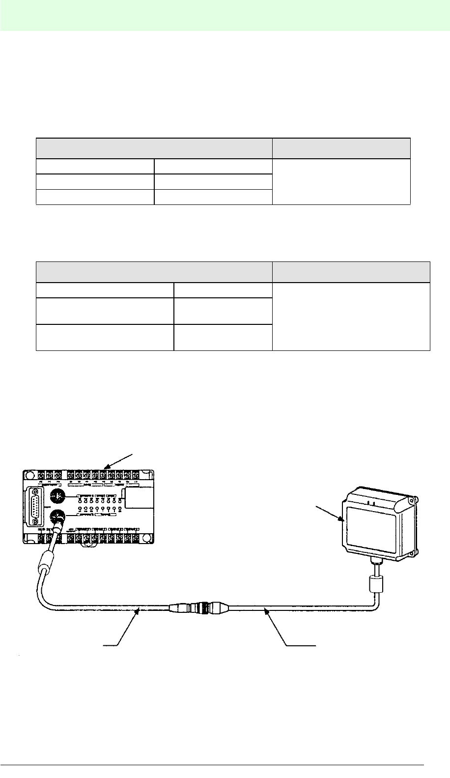
IDENT-M System V
Technical Data
Date of issue 03.05.2001
189
Subject to reasonable modifications due to technical advances. Copyright Pepperl+Fuchs, Printed in Germany
Pepperl+Fuchs Group • Tel.: Germany (06 21) 7 76-0 • USA (330) 4 25 35 55 • Singapore 7 79 90 91 • Internet http://www.pepperl-fuchs.com
Cable Flexibility
A very flexible robot cable is used for the read/write head. The cable has a lifetime of
500,000 and 2,500,000 bends or twists on the following conditions:
Bending
Twisting
When the read/write head is to be mounted movable, make sure that the read/write
head cable can be freely twisted and bended. When an extension cable is used it
should be fixed, since it is sensitive to bending and twisting.
Test conditions Number of bends
Load: 1 kg Current: 50 mA
500,000 Bending radius: 20 mm Bending angle: 90°
Bending velocity: 50/min
Test conditions Number of twists
Length of test: 1 m Current: 50 mA
2,500,000
Tension: 0 g Twisting angle: 90°
for both directions
Twisting velocity:
50/min.
MVI-D2-2HRX
Read/write head
Read/write head cable
(Insensitive to twisting strain and
bending load)
Extension cable
(Sensitive to twisting strain
bending load)
Ferrite absorbers are to be placed upon the cable
at a distance of 3 cm from the cable exits.

IDENT-M System V
Technical Data
Date of issue 03.05.2001
190
Subject to reasonable modifications due to technical advances. Copyright Pepperl+Fuchs, Printed in Germany
Pepperl+Fuchs Group • Tel.: Germany (06 21) 7 76-0 • USA (330) 4 25 35 55 • Singapore 7 79 90 91 • Internet http://www.pepperl-fuchs.com
11.1 Lifetime of the Data Carrier's Battery
The data carrier has a built-in lithium battery. The battery has the following current
consumption:
Calculate and check the battery life with the current values indicated above.
Calculation of the Battery Life
The lifetime of the battery L (year) can be calulated by means of the activation rate A
of the data carrier's transmission time.
Transmission
condition between
read/write head and
data carrier
Current consumption
Function
Designa-
tion Current value
No transmission Standby
current
For MVC-60-64K:
approx. 20 mA or less
Receiving data in the data
carrier; detecting
communication signals from
read/write heads
Transmission Active
current
For MVC-60-64K:
Approx. 12 mA or less
(when the LED of the
data carrier is not
illuminated.)
approx. 15 mA or less
(when the LED of the
data carrier is
illuminated.)
Execution of write or read
operations by means of read/
write heads
TC * N D
Activation rate A = *
24*3600*1000 365
Tc (ms) Transfer time between the read/write head and the data carrier (see
page 36)
N Number of transfer times of the data carrier per day
D Working days per year
3,600 3,600 s/h
24 24 hours/day
1000 Constant

IDENT-M System V
Technical Data
Date of issue 03.05.2001
191
Subject to reasonable modifications due to technical advances. Copyright Pepperl+Fuchs, Printed in Germany
Pepperl+Fuchs Group • Tel.: Germany (06 21) 7 76-0 • USA (330) 4 25 35 55 • Singapore 7 79 90 91 • Internet http://www.pepperl-fuchs.com
Example
With an average number of 32 bytes per transmission during the reading process
(transmission code: 0208), with the data carrier (MVC-60-64K) and the conditions
mentioned below, the average lifetime L will be approx. 8.27 years.
Battery life L (year) A =
1,600 * 0.9
365 * 24 [A * active current + (1 - A) * standby current]
1,900 Battery capacity (mAh)
0.9 Safety deduction (taking into account the data carrier's production and
delivery time)
365 365 days/year 24 24 h/day A Activation period
Active current : approx. 12 mA or less (when the LED is not illuminated)
Standby current: approx. 20 µA or less
15.9 * 2000 300
Tc = 11.3 + 0.143 * 32 + M1( ) * 0.5 + M2 ( ) * 5.59 = 15.9 (ms)
128
Battery life L (year) A = = 8.27
1900 * 0.9
365 * 24 [0.0003 * 12 + (1 - 0.0003) * 0.02]
Activation rate A = * = 0.0003
24*3600*1000 365
32 32
256
N 2000 number/day D 300 days/year
Active current 12 mA Standby current 20 µA = 0.020 mA

IDENT-M System V
Technical Data
Date of issue 03.05.2001
192
Subject to reasonable modifications due to technical advances. Copyright Pepperl+Fuchs, Printed in Germany
Pepperl+Fuchs Group • Tel.: Germany (06 21) 7 76-0 • USA (330) 4 25 35 55 • Singapore 7 79 90 91 • Internet http://www.pepperl-fuchs.com
Checking the Battery Life
Check the service life and the battery voltage of the battery integrated in the data
carrier by means of the transmission function between the host controller and the data
carrier (checking the battery life of the data carrier and self-diagnosis of the data
carrier).
• If an error is found during the test, the data carrier sends an error message to the
host controller (service life alarm or low battery voltage alarm, see page 185).
In case the battery functions properly, the data carrier sends an acknowledgement
containing the battery utilisation rate. In case the battery voltage is too low, the
corresponding error message is added to the acknowledgement. This is also done, in
case other communication operations are conducted at the same time (see page
185).
Be sure to substitute the data carrier immediately, in case one of these errors occurs.
• Battery utilisation rate (%)
Error code Error designation Explanation
3A Low battery voltage alarm Voltage level of battery is too low
3B Battery service life alarm Battery service life exceeds 100 %
Standby time Current year and month - production year and month - active
operation time 1 -
0.02 Standby current (20 mA = 0.020 mA)
Active
operation
time1
While the data carrier communicates with the read/write head, the
LED on the data carrier does not light. (Stores data in the memory
addresses 804A to 804Dh of the data carrier).
12 Current = 12 mA
Active
operation
time2
While the data carrier communicates with the read/write head, the
LED on the data carrier lights. (Stores data in the memory
addresses 804A to 8051Dh of the data carrier).
15 Current = 15 mA (during communication with the read/write head
and illuminated LED on the data carrier).
1,900 Battery capacity (1,900 mA • h)
0.9 Safety deduction (In order to take into account the time interval
between production and sale of the data carrier).
Battery utilisation rate =
Standby time * 0.02 + active operation time1 + 12 + active operation time2 * 15
1900 * 0.9 * 100 [%]

IDENT-M System V
Appendix
Date of issue 03.05.2001
193
Subject to reasonable modifications due to technical advances. Copyright Pepperl+Fuchs, Printed in Germany
Pepperl+Fuchs Group • Tel.: Germany (06 21) 7 76-0 • USA (330) 4 25 35 55 • Singapore 7 79 90 91 • Internet http://www.pepperl-fuchs.com
12 Appendix
12.1 ASCII (JIS) Code Table
12.1.1 Binary/Hexadecimal Table
• How to use an ASCII code table
Capital letter “A” is located on “4” of the higher-order bit and on “1” of the lower-order
bit. Thus, the ASCII code of “A” is à “41h”.
12.1.2 Octal Table
How to use an ASCII code table
Capital letter “A” is located on “10” of the upper two digits and on “1” of the lower digit.
Thus, the ASCII code of “A” is à “1018”.
Lower-order bit
bin 0000 0001 0010 0011 0100 0101 0110 0111 1000 1001 1010 1011 1100 1101 1110 1111
Higher-order bit
bin hex 0 1 2 3 4 5 6 7 8 9 A B C D E F
0000 0NUL SOH STX ETX EOT ENQ ACK BEL BS HT LF VT FF CR SO SI
0001 1DLE DC1 DC2 DC3 DC4 NAK SYN ETB CAN EM SUB ESC FS GS RS US
0010 2SP ! " # $ % & ' ( ) * + , - . /
0011 30123456789 : ; <=>?
0100 4@A B C D E F G H I J K L MN O
0101 5PQRSTUVWXYZ[\]^_
0110 6` abcde f gh i j k lmno
0111 7pqrstuvwxyz{ | }~DEL
Lower digit
Upper two digits
octal 01234567
00 NUL SOH STX ETX EOT ENQ ACK BEL
01 BS HT LF VT FF CR SO SI
02 DLE DC1 DC2 DC3 DC4 NAK SYN ETB
03 CAN EM SUB ESC FS GS RS US
04 SP ! " # $ % & '
05 ()*+,-./
06 01234567
07 89 : ; <=>?
10 @A B C D E F G
11 HIJKLMNO
12 PQRSTUVW
13 XYZ[\]^_
14 `abcdefg
15 hi jklmno
16 pq r s t uvw
17 xyz { | }~DEL
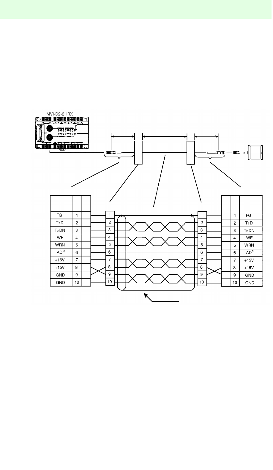
IDENT-M System V
Appendix
Date of issue 03.05.2001
194
Subject to reasonable modifications due to technical advances. Copyright Pepperl+Fuchs, Printed in Germany
Pepperl+Fuchs Group • Tel.: Germany (06 21) 7 76-0 • USA (330) 4 25 35 55 • Singapore 7 79 90 91 • Internet http://www.pepperl-fuchs.com
12.1.3 Extension of the Read/Write Head Cable
The following cables are delivered standard as connection cables between the MVI-
D2-2HRX and the read/write head: MVK-5 (5 m), MVK-10 (10 m), MVK-20 (20 m) and
MVK-30 (30 m). In case a longer cable than the MVK-30 (30 m) is required, the cable
length can be extended to 1,200 m.
Extension from 30 m to 200 m
Use of cables with a core cross-section of 0.5 to 1.25 mm2.
1) Crop the MVK-5 cable to a length below 1 m on the MVI-D2-2HRX connection side.
2) Crop the MVK-5 cable to a length below 1 m on the read/write head connection side.
3) (Two positions) Wire the AD signal (antenna power monitor) and a GND line as a pair.
4) Extension cable
a. Recommended Cables
Measuring instrument cables having the following features are best suited as
extension cables:
• Insensitive to induction voltages
• Lightweight
• Low external dimension
1 m or 1)
less
1 m or 2)
less
Read/write head
MVI-D2-2HRX side of MVK-5 Read/write head side of MVK-5
Terminal block 1 Terminal block 2
Extension cable
Screen
Signal
name
Pin
No.
Cable
colour
Blue
White
Yellow
Orange
Green
Red
Pink
Black
Brown
Blue
White
Yellow
Orange
Green
Red
Pink
Black
Brown
Cable
colour
Pin
No.
Signal
name
30 m ... 200 m
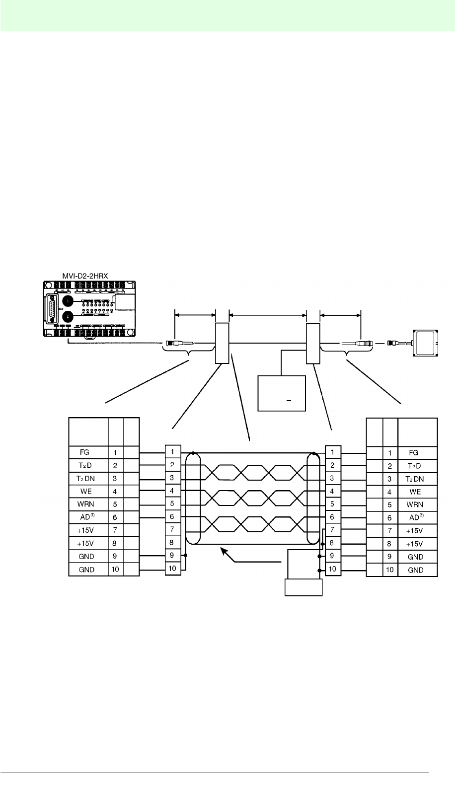
IDENT-M System V
Appendix
Date of issue 03.05.2001
195
Subject to reasonable modifications due to technical advances. Copyright Pepperl+Fuchs, Printed in Germany
Pepperl+Fuchs Group • Tel.: Germany (06 21) 7 76-0 • USA (330) 4 25 35 55 • Singapore 7 79 90 91 • Internet http://www.pepperl-fuchs.com
b. Maximum Cable Length
The supply voltage from the MVI-D2-2HRX to the read/write head drops
proportional to the cable length. Determine the conductivity and the extension
cable length by means of the calculation example given on the next page, in
order to ensure that the voltage drop is less than 1 V.
c. Extension from 200 m to 1,200 m
Use cables with a core cross section of about 0.5 mm2. In this case, the read/
write head should not receive any voltage from the MVI-D2-2HRX. In order to
provide the read/write head with voltage, a 15 VDC power supply should be
installed alongside the read/write head. In any case, it is necessary to connect
24 VDC to the external power supply connection of the MVI-D2-2HRX. The
cable between the read/write head and the MVI-D2-2HRX is only used for data
transmission, not for power supply.
1) Crop the MVK-5 cable to a length below 1 m on the MVI-D2-2HRX connection side.
2) Crop the MVK-5 cable to a length below 1 m on the read/write head connection side.
3) Recommended cable: Lapp cable UNITRONIC®-LiZCY(TP) or equivalent.
4) Recommended power supply: Lütze NG3-0772 Stab.
1 m or 1)
less
2)
less
1 m or
Read/write head
White
Yellow
Orange
Green
Red
Pink
Black
Brown
Blue
White
Yellow
Orange
Green
Red
Pink
Black
Brown
Screen
Signal
name
Pin
No.
Cable
colour
Blue
Extension cable
Relais terminal block 2
Cable
colour
Pin
No.
Signal
name
MVI-D2-2HRX side of MVK-5 Read/write head side of MVK-5
Relais terminal block 1
Power
Supply 4)
Power
Supply
15 VDC + 5 %
250 mA
200 m ... 1,200 m

IDENT-M System V
Appendix
Date of issue 03.05.2001
196
Subject to reasonable modifications due to technical advances. Copyright Pepperl+Fuchs, Printed in Germany
Pepperl+Fuchs Group • Tel.: Germany (06 21) 7 76-0 • USA (330) 4 25 35 55 • Singapore 7 79 90 91 • Internet http://www.pepperl-fuchs.com
Calculation Examples
Calculation example for a maximum length of the extension cable (previous page).
For a two wire cable, applying the following formula:
RD = Rr *(Lm/1,000) * 2/2
Maximum cable length Lm [m] = (RD ´ 1,000)/Rr
RD [9]: Permissible lead resistance of the extension cable (there and back)
RD = ED / IS = 1 / 0.25 = 4 (9)
ED [V]: Permissible voltage drop between the MVI-D2-2HRX and
the read/write head (maximum 1V)
IS [A]: Current consumption of the read/write head (0.25 A)
RR [9]: Lead resistance per 1 km at operating temperature
RR : R20 {1 + =20 (T-20)}
R20 [=/km]: Lead resistance at 20 °C
=20:Temperature coefficient (0.00393)
T [°C]: Operating temperature
Lm [m] = 4000/Rr
The following table shows calculation examples for T = 70 °C
Conductive area [mm²] 0.5 0.75 0.9 1.25
R20: Lead resistance at 20 °C [9/km] 34.0 25.5 21.7 17.2
R70 : Lead resistance at 70 °C [9/km] 40.7 30.5 26.0 20.6
Maximum cable length [m] 98.0 131.0 154.0 194.0
External dimension (including the covering [mm]) 13.0 13.5 14.0 15.0

IDENT-M System V
Notizen
Date of issue 03.05.2001
197
Subject to reasonable modifications due to technical advances. Copyright Pepperl+Fuchs, Printed in Germany
Pepperl+Fuchs Group • Tel.: Germany (06 21) 7 76-0 • USA (330) 4 25 35 55 • Singapore 7 79 90 91 • Internet http://www.pepperl-fuchs.com

IDENT-M System V
Notizen
Date of issue 03.05.2001
198
Subject to reasonable modifications due to technical advances. Copyright Pepperl+Fuchs, Printed in Germany
Pepperl+Fuchs Group • Tel.: Germany (06 21) 7 76-0 • USA (330) 4 25 35 55 • Singapore 7 79 90 91 • Internet http://www.pepperl-fuchs.com

IDENT-M System V
Notizen
Date of issue 03.05.2001
199
Subject to reasonable modifications due to technical advances. Copyright Pepperl+Fuchs, Printed in Germany
Pepperl+Fuchs Group • Tel.: Germany (06 21) 7 76-0 • USA (330) 4 25 35 55 • Singapore 7 79 90 91 • Internet http://www.pepperl-fuchs.com

IDENT-M System V
Notizen
Date of issue 03.05.2001
200
Subject to reasonable modifications due to technical advances. Copyright Pepperl+Fuchs, Printed in Germany
Pepperl+Fuchs Group • Tel.: Germany (06 21) 7 76-0 • USA (330) 4 25 35 55 • Singapore 7 79 90 91 • Internet http://www.pepperl-fuchs.com
With regard to the supply of products, the current issue of the following document is applicable:
The General Terms of Delivery for Products and Services of the Electrical Industry, as published by
the Central Association of the "Elektrotechnik und Elektroindustrie (ZVEI) e.V.v",
including the supplementary clause "Extended reservation of title".
We at Pepperl+Fuchs recognise a duty to make a contribution to the future.
For this reason, this printed matter is produced on paper bleached without the use of chlorine.

35336 04/01 01