Phorus CAPRICA2L Play-Fi Module User Manual
Phorus, Inc. Play-Fi Module
UserManual.wiki
>
Phorus
>
CAPRICA2L User Manual
User manual
Navigation menu
Upload a User Manual
Namespaces
Wiki Guide
HTML
PDF
Info
Views
User Manual
Discussion / Help
Navigation
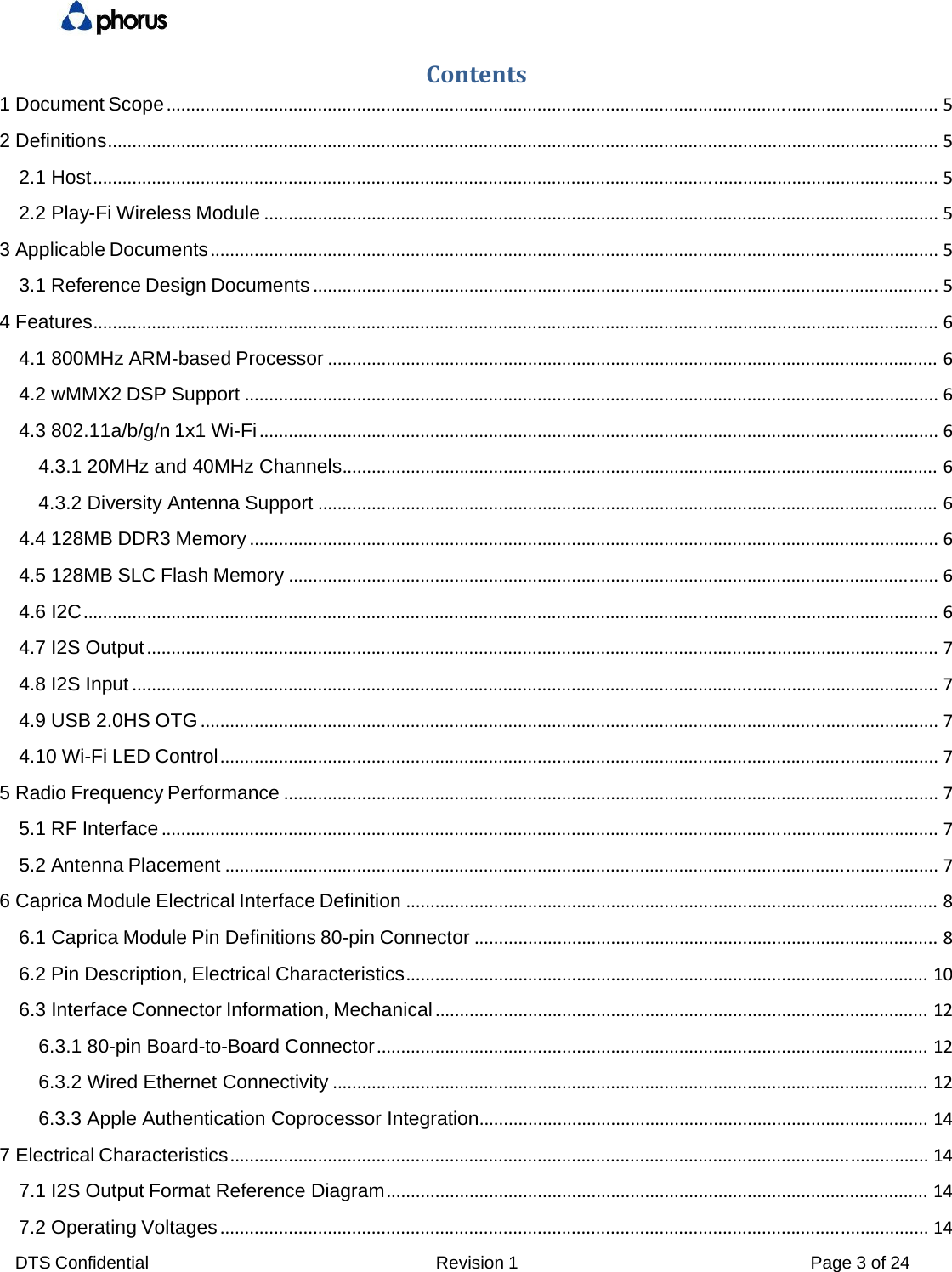
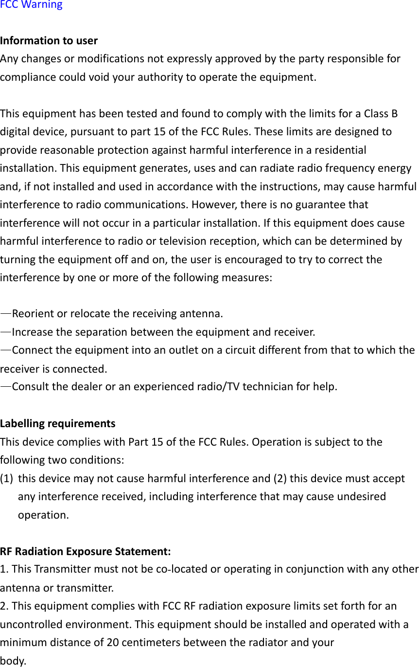
![DTS Confidential Revision 1 Page 9 of 24 38 GND 39 GND 40 LED[0] Reserved 41 MMC1_CLK Reserved 42 LED[1] Reserved 43 MMC1_CMD/XD_CLE Reserved 44 GND 45 MMC1_D0/XD_D3 Reserved 46 SCL1 I2C1 47 MMC1_D1/XD_D4 Reserved 48 SDA1 I2C1 49 MMC1_D2/XD_nRE Reserved 50 GND 51 MMC1_D3/XD_nCE Reserved 52 SSP2_CLK Reserved 53 GND 54 SSP2_FRM Reserved 55 I2S_MCLK I2S 56 SSP2_TXD Reserved 57 I2S_BCLK I2S 58 SSP2_RXD Reserved 59 I2S_LRCK I2S 60 GND 61 I2S_SDOUT I2S 62 GND 63 I2S_SDIN I2S 64 GPIO0 Reserved 65 I2S1_BCLK/AC97_BCLK I2S1 66 GPIO1 Apple Auth 67 I2S1_LRCK/AC97_DIN0 I2S1 68 GPIO2 Reserved 69 I2S1_SDOUT/AC97_DOUT I2S1 70 GPIO3 Reserved 71 GND 72 GPIO4 Reserved 73 RSR_IN# Reserved 74 GPIO5 Reserved 75 WIFI_LED_G WIFI_LED 76 GPIO6 Reserved 77 INT_TO_MCU INT 78 GPIO7 Reserved 79 I2C_ADDR ADDR 80 EXT_WAKEUP Reserved ](https://usermanual.wiki/Phorus/CAPRICA2L/User-Guide-2746543-Page-9.png)
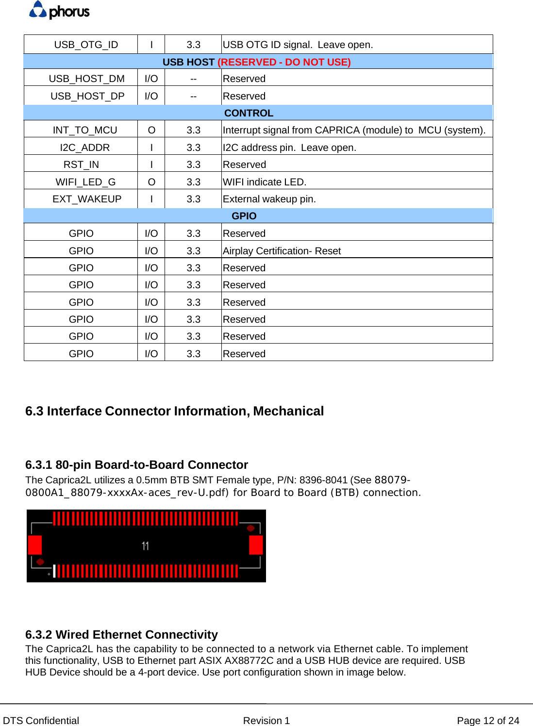
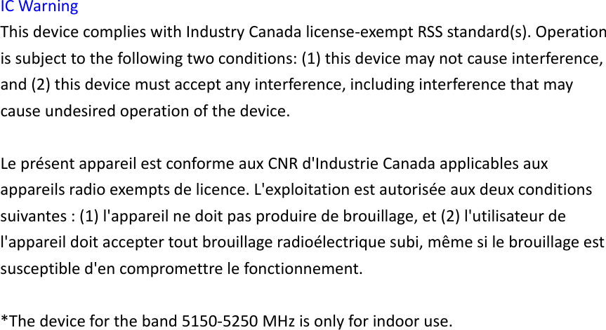
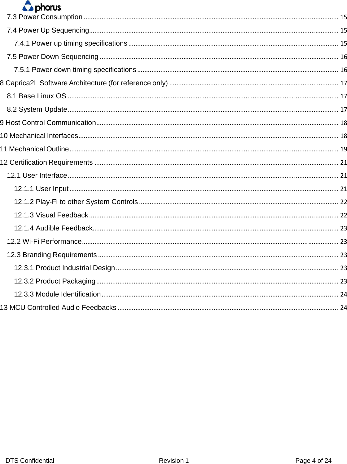
![DTS Confidential Revision 1 Page 11 of 24 SSP2_TXD O 3.3 Reserved SSP2_CLK O 3.3 Reserved SSP2_FRM O 3.3 Reserved JTAG (Optional) TDI I 3.3 JTAG data input Required TMS I 3.3 JTAG mode select Required TCK I 3.3 JTAG clock Required TDO O 3.3 JTAG data output Required TRSTI 3.3 JTAG reset Required UART UART3_RXD I 3.3 Reserved UART3_TXD O 3.3 Reserved UART3_RTS O 3.3 Reserved UART3_CTS I 3.3 Reserved I2C SC I 3.3 I2C_SCL; Connect to MCU. Caprica is slave device. SDA I/O 3.3 I2C_SDA; Connect to MCU. Caprica is slave device. SCLI/O 3.3 I2C_SCL; Airplay Certification SDA1 I/O 3.3 I2C_SDA; Airplay Certification AUDIO I2S_MCLK O 3.3 MCLK, audio master clock output from CAPRICA I2S_LRCK O 3.3 LRCK, audio word clock output from CAPRICA. 44.1KHz I2S_BCLK O 3.3 BCLK, audio bit clock output from CAPRICA. 2.82 MHz I2S_SDI I 3.3 DATA, audio data input to CAPRICA. I2S_SDOUT O 3.3 DATA, audio data output from CAPRICA. I2S1_BCLK/AC97_BCI 3.3 BCLK, BT audio bit clock input to CAPRICA. I2S1_LRCK/AC97_DII 3.3 LRCK, BT audio word clock input to CAPRICA. I2S1_SDOUT/AC97_DOUTI 3.3 DATA, BT audio data input to CAPRICA. ETHERNET (RESERVED - DO NOT USE) RJ_RX I -- Reserved RJ_RX I -- Reserved RJ_TX O -- Reserved RJ_TX O -- Reserved LED[0] O 3.3 Reserved LED[1] O 3.3 Reserved USB USB_OTG_DM I/O -- USB OTG data signal. As host mode only. USB_OTG_DP I/O -- USB OTG data signal. As host mode only. BT DisableBT DisableBT Disable](https://usermanual.wiki/Phorus/CAPRICA2L/User-Guide-2746543-Page-11.png)