User manual

DTS Confidential Revision 1 Page 1 of 24
Caprica
2L
Play-FiTM Wireless Module
Design
Guide
PHORUS-CAP-TSD- 0010 (2L)
April 20, 2015
Revision 1

DTS Confidential Revision 1 Page 2 of 24
Document Change Summary
Date: Revision:
Changes:
A
uthor:
A
pprover:
4/20/201
5
X1
Initial Release
AK
MC

DTS Confidential Revision 1 Page 3 of 24
Contents
1 Document Scope..............................................................................................................................................................5
2 Definitions..........................................................................................................................................................................5
2.1 Host.............................................................................................................................................................................5
2.2 Play-Fi Wireless Module..........................................................................................................................................5
3 Applicable Documents.....................................................................................................................................................5
3.1 Reference Design Documents................................................................................................................................5
4 Features.............................................................................................................................................................................6
4.1 800MHz ARM-based Processor.............................................................................................................................6
4.2 wMMX2 DSP Support..............................................................................................................................................6
4.3 802.11a/b/g/n 1x1 Wi-Fi...........................................................................................................................................6
4.3.1 20MHz and 40MHz Channels..........................................................................................................................6
4.3.2 Diversity Antenna Support...............................................................................................................................6
4.4 128MB DDR3 Memory.............................................................................................................................................6
4.5 128MB SLC Flash Memory.....................................................................................................................................6
4.6 I2C...............................................................................................................................................................................6
4.7 I2S Output..................................................................................................................................................................7
4.8 I2S Input.....................................................................................................................................................................7
4.9 USB 2.0HS OTG.......................................................................................................................................................7
4.10 Wi-Fi LED Control...................................................................................................................................................7
5 Radio Frequency Performance......................................................................................................................................7
5.1 RF Interface...............................................................................................................................................................7
5.2 Antenna Placement..................................................................................................................................................7
6 Caprica Module Electrical Interface Definition.............................................................................................................8
6.1 Caprica Module Pin Definitions 80-pin Connector...............................................................................................8
6.2 Pin Description, Electrical Characteristics...........................................................................................................10
6.3 Interface Connector Information, Mechanical.....................................................................................................12
6.3.1 80-pin Board-to-Board Connector.................................................................................................................12
6.3.2 Wired Ethernet Connectivity..........................................................................................................................12
6.3.3 Apple Authentication Coprocessor Integration............................................................................................14
7 Electrical Characteristics...............................................................................................................................................14
7.1 I2S Output Format Reference Diagram
...............................................................................................................14
7.2 Operating Voltages.................................................................................................................................................14

DTS Confidential Revision 1 Page 4 of 24
7.3 Power Consumption...............................................................................................................................................15
7.4 Power Up Sequencing............................................................................................................................................15
7.4.1 Power up timing specifications......................................................................................................................15
7.5 Power Down Sequencing......................................................................................................................................16
7.5.1 Power down timing specifications.................................................................................................................16
8 Caprica2L Software Architecture (for reference only)...............................................................................................17
8.1 Base Linux OS........................................................................................................................................................17
8.2 System Update........................................................................................................................................................17
9 Host Control Communication........................................................................................................................................18
10 Mechanical Interfaces..................................................................................................................................................18
11 Mechanical Outline.......................................................................................................................................................19
12 Certification Requirements.........................................................................................................................................21
12.1 User Interface........................................................................................................................................................21
12.1.1 User Input.......................................................................................................................................................21
12.1.2 Play-Fi to other System Controls................................................................................................................22
12.1.3 Visual Feedback............................................................................................................................................22
12.1.4 Audible Feedback..........................................................................................................................................23
12.2 Wi-Fi Performance................................................................................................................................................23
12.3 Branding Requirements.......................................................................................................................................23
12.3.1 Product Industrial Design.............................................................................................................................23
12.3.2 Product Packaging........................................................................................................................................23
12.3.3 Module Identification.....................................................................................................................................24
13 MCU Controlled Audio Feedbacks............................................................................................................................24

DTS Confidential Revision 1 Page 5 of 24
1 Document Scope
This document describes interface requirements for the second-generation Play-Fi Wireless Module, also
known as Caprica2L. Caprica2L is a WiFi audio module designed for wireless, multi-room audio
distribution. Caprica2L streams with 16 bit resolution and 44.1 KHz sampling rate. The module may be
utilized in speakers, stand-alone receivers or incorporated into other products like AVRs. This document
provides guidelines for the inclusion of this module into such products.
2 Definitions
2.1 Host
Host refers to the off board MCU that processes user interactions and controls audio processing.
2.2 Play-Fi Wireless Module
Play-Fi Wireless Module refers to the Caprica2L module with integrated Wi-Fi radio.
3 Applicable Documents
3.1 Reference Design Documents
The following documents form a part of this specification. Each utilized and referenced document shall be
the most recent released issue.
Phorus Reference Documentation
PHORUS-CAP-TSD-0004-Caprica-Host-Communication-Protocol
BTB Connector datasheet (88079-0800A1_88079-xxxxAx-aces_rev-U.pdf)
BTB Connector Specification (88079_SPEC-88069-xxxx_rev-L.pdf)
Play-Fi Module Outline and Mounting Drawings
(Caprica_2L_PCB_RevA.DWG, Caprica_2L_PCB_RevA.pdf)
3D design file, outline and mounting (Caprica_2L_PCB_RevA.stp)

DTS Confidential Revision 1 Page 6 of 24
4 Features
The Caprica2L Play-Fi Wireless module is a programmable, high-performance, encapsulated design
that enables manufacturers to wirelessly distribute audio to multiple devices. Sources can include Play-
Fi Applications, Play-Fi Drivers, or other sources of a manufacturer's choice, such as Bluetooth, via a
I2S input. The design supports a number of interfaces that enable easy integration of the module to
traditional consumer electronic designs. Caprica2L features include:
4.1 800MHz ARM-based Processor
Marvell PXA166 ARM v6/v7-compatible core:
Up to 1848 DMIPS
16K/16K L1 I/D Caches
64K L2 Cache
5-8 Stage Variable Pipeline
Retire up to 2 Instructions per Cycle
Out-of-Order Execution
Three-level Branch Prediction
4.2 wMMX2 DSP Support
Up to 1600 MMACS per second. Supports complex Digital Signal Processing with little CPU overhead.
Audio CODECs including MP3, WMA and AAC utilize the wMMX2 engine.
4.3 802.11a/b/g/n 1x1 Wi-Fi
Dual-band design with 2.4GHz and 5GHz support. Supports transmit modes up to 150mbps.
4.3.1 20MHz and 40MHz Channels
Supported in both 2.4 and 5 GHz bands
4.3.2 Diversity Antenna Support
Caprica2L supports two antenna connections in a diversity antenna configuration (using
orthogonal mounting).
4.4 128MB DDR3 Memory
High-performance memory for maximum processor and network performance.
4.5 128MB SLC Flash Memory
4.6 I2C
The I2C Interface is the port which Caprica2L communicates with the external system. The
communication protocol "Play-Fi Host Communication Protocol" is described in a separate document
(PHORUS-CAP-
TSD-0004-Caprica-Host-Communication-Protocol).
The Caprica2L Module is configured
as a I2C slave with address 0x52.
BT Disable
DTS Confidential Revision 1 Page 7 of 24
4.7 I2S Output
Caprica2L outputs digital audio via an I2S port. Caprica acts as the master device. The format is
MSB Left Justified.
LRCLK- 44.1 KHz
BITCLK- 2.8224 MHz (64 * Fs)
Data – 16 bits of data followed by 16 bits forced 0 on each rising/falling edge of LRCLK
This format cannot be changed.
4.8 I2S Input
Caprica2L can accept auxiliary inputs via I2S. Caprica is the slave here. The format is MSB Left Justified.
LRCLK- 8KHz, 16KHz, 22.05KHz, 32KHz, 44.1KHz, 48KHz, 96Khz. (PIN 67)
BITCLK- 2.8224 MHz (64 * Fs) (PIN 65)
Data – 16 bits of data followed by 16 bits forced 0 on each rising/falling edge of LRCLK
This format cannot be changed. (PIN 69)
.
4.9 USB 2.0HS OTG
Configured as a Host in standard configurations. All Play-Fi devices require a USB Host is required for Factory
USB updates.
4.10 Wi-Fi LED Control
Caprica2L controls a consumer-facing LED that gives indication as to Wi-Fi status.
5 Radio Frequency Performance
5.1 RF Interface
Wi-Fi RF connectivity is provided by 2 dual-band antennas, connected via miniature RF cables. These
antennas are tuned for both 2.4GHz and 5GHz operation.
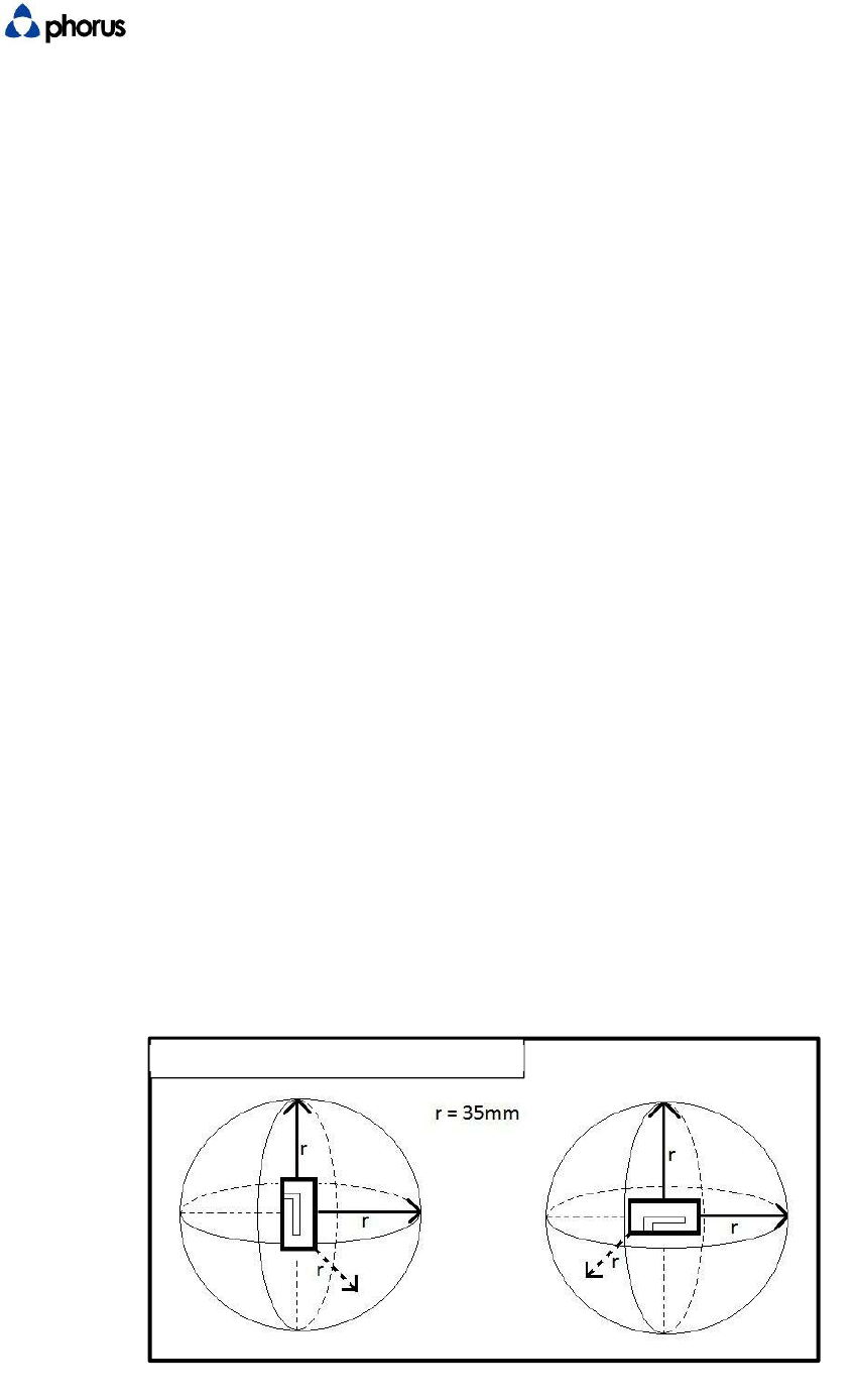
5.2 Antenna Placement
For optimal RF coverage, antennas should be mounted orthogonally to each other. Each antenna should
be at least 35mm away from any other metal object in 3D space. The antennas should be mounted as
high on the vertical axis as possible while maintaining 35mm distance from other metal objects. The
farther apart the antennas are mounted from each other the better, however, the feed line from
antenna to
Wi-Fi Module connection should not exceed 150mm to minimize RF losses through wire.
Figure 5.2.1
DTS Confidential Revision 1 Page 8 of 24
6 Caprica Module Electrical Interface Definition
6.1 Caprica Module Pin Definitions 80-pin Connector
BTB Conn. Net Function
Name CAPRICA 2L
1 V1_1 Power (3.3V)
2 V5_2 Power (1.8V)
3 V1_1 Power (3.3V)
4 V5_2 Power (1.8V)
5 V1_1 Power (3.3V)
6 V2_2 Power (1.8V)
7 V3_3 Power (1.1V)
8 V2_2 Power (1.8V)
9 V3_3 Power (1.1V)
10 3V3_RTC RTC (3.3V)
11 V3_3 Power (1.1V)
12 GND
13 DC_5V Power (5V)
14 USB_OTG_ID Reserved
15 GND
16 GND
17 TDI JTAG
18 USB_OTG_DM USB_OTG
19 TMS JTAG
20 USB_OTG_DP USB_OTG
21 TCK JTAG
22 GND
23 TDO JTAG
24 USB_HOST_DM Reserved
25 TRST JTAG
26 USB_HOST_DP Reserved
27 UART3_TXD Reserved
28 GND
29 UART3_RXD Reserved
30 RJ_TX+ Reserved
31 UART3_CTS Reserved
32 RJ_TX- Reserved
33 UART3_RTS Reserved
34 RJ_RX+ Reserved
35 SCL I2C
36 RJ_RX- Reserved
37 SDA I2C

DTS Confidential Revision 1 Page 9 of 24
38 GND
39 GND
40 LED[0] Reserved
41 MMC1_CLK Reserved
42 LED[1] Reserved
43 MMC1_CMD/XD_CLE Reserved
44 GND
45 MMC1_D0/XD_D3 Reserved
46 SCL1 I2C1
47 MMC1_D1/XD_D4 Reserved
48 SDA1 I2C1
49 MMC1_D2/XD_nRE Reserved
50 GND
51 MMC1_D3/XD_nCE Reserved
52 SSP2_CLK Reserved
53 GND
54 SSP2_FRM Reserved
55 I2S_MCLK I2S
56 SSP2_TXD Reserved
57 I2S_BCLK I2S
58 SSP2_RXD Reserved
59 I2S_LRCK I2S
60 GND
61 I2S_SDOUT I2S
62 GND
63 I2S_SDIN I2S
64 GPIO0 Reserved
65 I2S1_BCLK/AC97_BCLK I2S1
66 GPIO1 Apple Auth
67 I2S1_LRCK/AC97_DIN0 I2S1
68 GPIO2 Reserved
69 I2S1_SDOUT/AC97_DOUT I2S1
70 GPIO3 Reserved
71 GND
72 GPIO4 Reserved
73 RSR_IN# Reserved
74 GPIO5 Reserved
75 WIFI_LED_G WIFI_LED
76 GPIO6 Reserved
77 INT_TO_MCU INT
78 GPIO7 Reserved
79 I2C_ADDR ADDR
80 EXT_WAKEUP Reserved
DTS Confidential Revision 1 Page 10 of 24
6.2 Pin Description, Electrical Characteristics
I/O Desc
r
iptions of C
A
PRICA
Net/ Signal (s) Type Level (V) Description
POWER
DC_5
P
5
Power supply input: 5V; AVDD5_USB; USB VBUS, analog
input for monitoring USB type A connector power.
V1_1
P
3.3
Power supply input: 3.3V
V5_2
P
1.8
Power supply input: 1.8V
V2_2
P
1.8
Power supply input: 1.8V_DDR
V3_3
P
1.1
Power supply input: 1.1V Power On Last
GND
P
0
Ground for power, signal and shielding.
RTC (Reserved
function)
3V3_RT
C
P
3.3
Real Time Clock (RTC) power supply input; 3.3V
SDIO (Reserved Function)
MMC1_D3/XD_nCE I/O
3.3
Reserved
MMC1_D2/XD_nRE I/O
3.3
Reserved
MMC1_D1/XD_D4 I/O
3.3
Reserved
MMC1_D0/XD_D3 I/O
3.3
Reserved
MMC1_CLK
O
3.3
Reserved
MMC1_CMD/XD_CLE I/O
3.3
Reserved
SPI (Reserved Function)
SSP2_RXD
I
3.3
Reserved
DTS Confidential Revision 1 Page 11 of 24
SSP2_TXD
O
3.3
Reserved
SSP2_CLK
O
3.3
Reserved
SSP2_FRM
O
3.3
Reserved
JTAG (Optional)
TDI
I
3.3
JTAG data input Required
TMS
I
3.3
JTAG mode select Required
TCK
I
3.3
JTAG clock Required
TDO
O
3.3
JTAG data output Required
TRS
T
I
3.3
JTAG reset Required
UART
UART3_RXD
I
3.3
Reserved
UART3_TXD
O
3.3
Reserved
UART3_RTS
O
3.3
Reserved
UART3_CTS
I
3.3
Reserved
I2C
SC I
3.3
I2C_SCL; Connect to MCU. Caprica is slave device.
SDA
I/O
3.3
I2C_SDA; Connect to MCU. Caprica is slave device.
SCL
I/O
3.3
I2C_SCL; Airplay Certification
SDA1
I/O
3.3
I2C_SDA; Airplay Certification
AUDIO
I2S_MCLK
O
3.3
MCLK, audio master clock output from CAPRICA
I2S_LRCK
O
3.3
LRCK, audio word clock output from CAPRICA. 44.1KHz
I2S_BCLK
O
3.3
BCLK, audio bit clock output from CAPRICA. 2.82 MHz
I2S_SDI I
3.3
DATA, audio data input to CAPRICA.
I2S_SDOUT
O
3.3
DATA, audio data output from CAPRICA.
I2S1_BCLK/AC97_BC
I
3.3
BCLK, BT audio bit clock input to CAPRICA.
I2S1_LRCK/AC97_DI
I
3.3
LRCK, BT audio word clock input to CAPRICA.
I2S1_SDOUT/AC97_D
O
U
T
I
3.3
DATA, BT audio data input to CAPRICA.
ETHERNET (RESERVED - DO NOT USE)
RJ_RX I
--
Reserved
RJ_RX I
--
Reserved
RJ_TX O
--
Reserved
RJ_TX O
--
Reserved
LED[0]
O
3.3
Reserved
LED[1]
O
3.3
Reserved
USB
USB_OTG_DM I/O
--
USB OTG data signal. As host mode only.
USB_OTG_DP I/O
--
USB OTG data signal. As host mode only.
BT Disable
BT Disable
BT Disable
DTS Confidential Revision 1 Page 12 of 24
USB_OTG_ID
I
3.3
USB OTG ID signal. Leave open.
USB HOST (RESERVED - DO NOT
USE)
USB_HOST_DM I/O
--
Reserved
USB_HOST_DP I/O
--
Reserved
CONTROL
INT_TO_MCU
O
3.3
Interrupt signal from CAPRICA (module) to MCU (system).
I2C_ADDR
I
3.3
I2C address pin. Leave open.
RST_IN I
3.3
Reserved
WIFI_LED_G
O
3.3
WIFI indicate LED.
EXT_WAKEUP
I
3.3
External wakeup pin.
GPIO
GPIO
I/O
3.3
Reserved
GPIO
I/O
3.3
Airplay Certification- Reset
GPIO
I/O
3.3
Reserved
GPIO
I/O
3.3
Reserved
GPIO
I/O
3.3
Reserved
GPIO
I/O
3.3
Reserved
GPIO
I/O
3.3
Reserved
GPIO
I/O
3.3
Reserved
6.3 Interface Connector Information, Mechanical
6.3.1 80-pin Board-to-Board Connector
The Caprica2L utilizes a 0.5mm BTB SMT Female type, P/N: 8396-8041 (See 88079-
0800A1_88079-xxxxAx-aces_rev-U.pdf)
for Board to Board (BTB) connection.
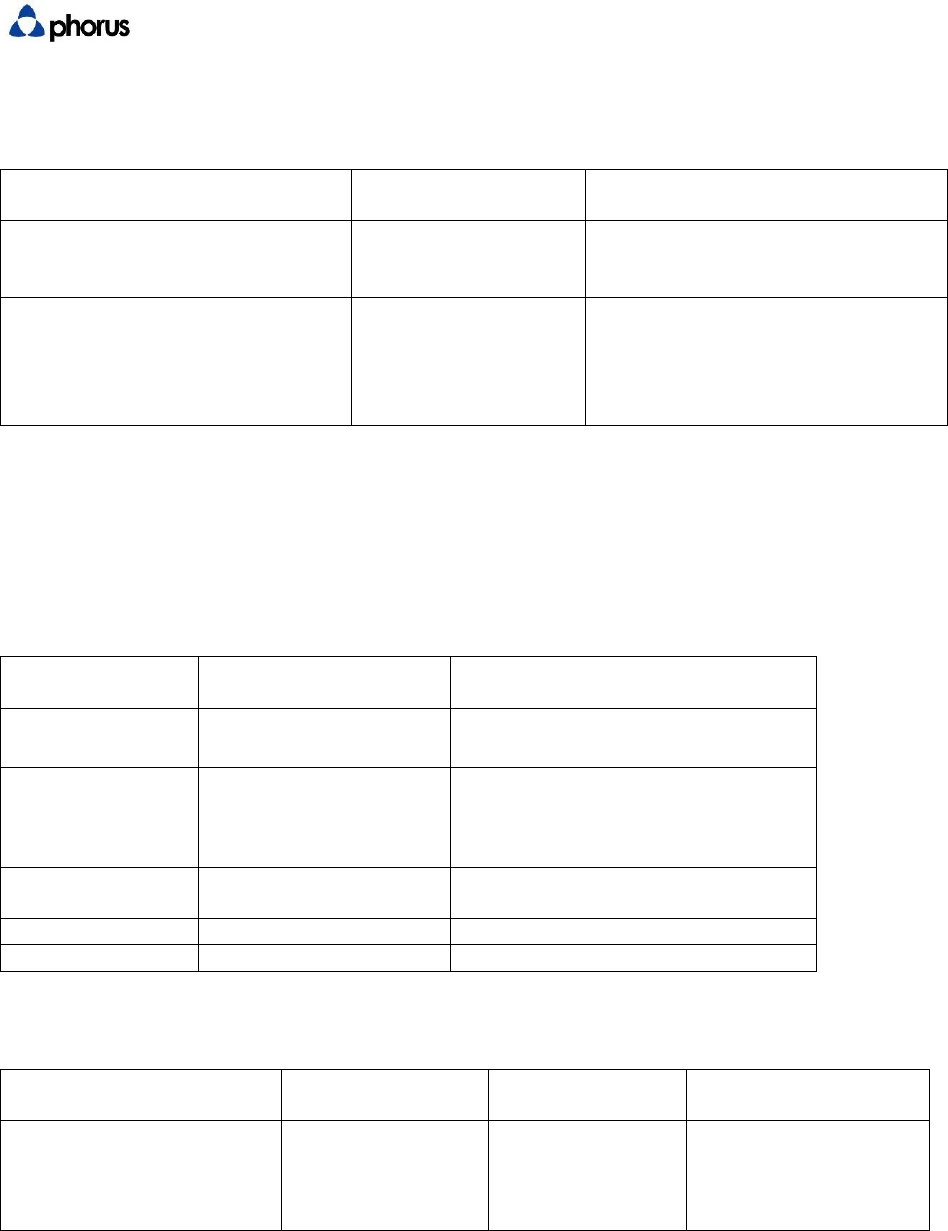
6.3.2 Wired Ethernet Connectivity
The Caprica2L has the capability to be connected to a network via Ethernet cable. To implement
this functionality, USB to Ethernet part ASIX AX88772C and a USB HUB device are required. USB
HUB Device should be a 4-port device. Use port configuration shown in image below.
DTS Confidential Revision 1 Page 13 of 24
USBtoETHERNET
(ASIXAX88772C)
PROCESSOR
Caprica2LModule
USBHUB
DEVICE
USBtoEthernet
(ASIXAS88772C)
RJ45
Receptacle
USBTypeA
Receptacle
(GL850G)
Optional
Port1
Port2
Port3
DTS Confidential Revision 1 Page 14 of 24
6.3.3 Apple Authentication Coprocessor Integration
Caprica2L supports integration of Apple Authentication Coprocessor. This is required for builds which wish to
certify Apple AirPlay. The interface between Caprica2L and Apple Coprocessor requires three connections, 2
connections for I2C and one for Reset. The Caprica2L pins designated for this are pin 46 (SCL1), pin 48 (SDA1),
and pin 66 (GPIO1) for reset. The GPIO1 connection is a jumper while SCL1 and SDA1 require external pullup
resistors. Apple MFi Accessory Interface Specification recommends using 2.2k Ohm resistors for pullup to Vcc
used to power Coprocessor.
7 Electrical Characteristics
This section describes the electrical characteristics of the module including power consumption power
sequencing, and timing diagrams
7.1 I2S Output Format Reference Diagram
This diagram displays the Left Justified (MSB) output format of Caprica2L I2S bus.
7.2 Operating Voltages
Symbol
Min
T
ypical
Max
Units
DC
_
5V(5V)
4.75
5.0 5.25 V
V1
_
1(3.3V)
2.97
3.3 3.6 V
V2
_
2(1.8V
_
DDR)
1.7
1.8 1.9 V
V5
_
2(1.8V)
1.7
1.8 1.9 V
V3
_
3(1.1V)
1.05
1.10 1.155 V
DTS Confidential Revision 1 Page 15 of 24
7.3 Power Consumption
Symbol V3 V5 V2 V1 5V
Voltages 1.1V 1.8V 1.8V 3.3V 5V
Test Point R219 R218 R217 R215 R216
Test Mode Avg. Max. Avg. Max. Avg. Max. Avg. Max. Avg. Max.
Normal (connect AP) 409.8 477.1 5.5 5.8 199.6 386.7 13.3 16.9 116.4 140.5
Play Music 1K Tone 412.8 439 5.6 5.8 201.2 254 15.1 14.9 117 131
Unit : mA
AveragePower0.9698 W
MaxPower1.2675 W
InRush2.5350 W
7.4 Power Up Sequencing
5V
3.3V
80%
1.8V DDR
1.8V
t1 80%
t3
t2
1.1V
7.4.1 Power up timing specifications
Symbol
Min
Unit
t1
0
ms
t2
0
ms
t3
0
ms
DTS Confidential Revision 1 Page 16 of 24
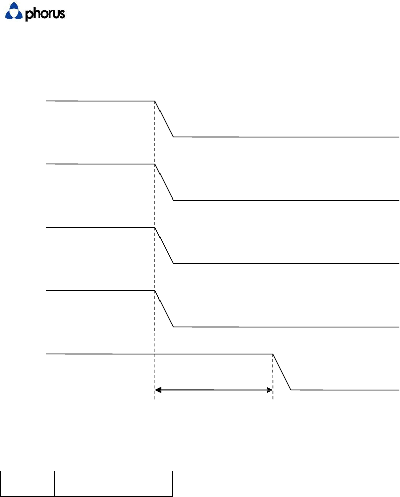
7.5 Power Down Sequencing
5V
3.3V
1.8V DDR
1.8V
1.1V
t1
7.5.1 Power down timing specifications
Symbol
Max
Unit
t1
10
ms

DTS Confidential Revision 1 Page 17 of 24
8 Caprica2L Software Architecture (for reference only)
The Caprica2L Software Architecture allows for Over the Air (OTA) reprogramming as well as
factory updates using a built in USB port.
8.1 Base Linux OS
The Base Linux OS (“OS”) includes the following sub-components:
Power management
Network connectivity
Dual-Band WiFi support
Notes:
Supports the WiFi standards 802.11a/b/g/n protocol
Supports all popular non-enterprise WiFi security scheme: WEP (64 and 128bit), WPA Pre-
Shared Key (WPA-PSK, TKIP + AES), and WPA2-PSK TKIP + AES
Supports WiFi Protected Setup (WPS) with Push Button Configuration (PBC) option
8.2 System Update
System update monitor automatically checks for software update availability
System update download and installation
Update via Network (OTA)
Factory Update via USB
DTS Confidential Revision 1 Page 18 of 24
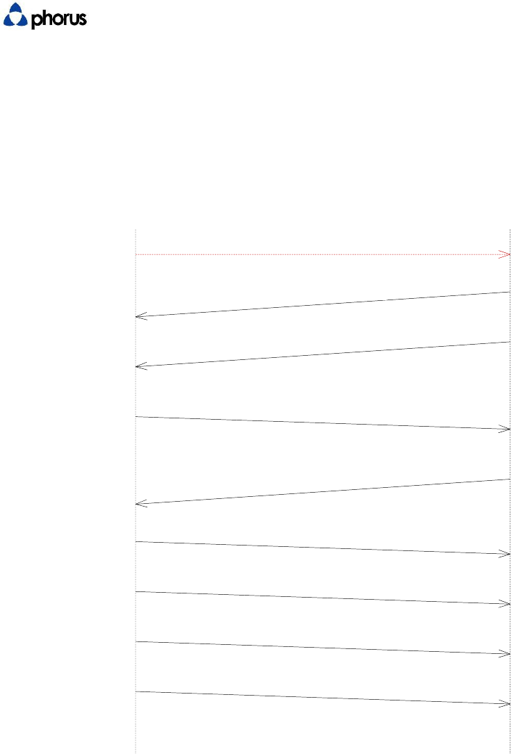
9 Host Control Communication
The following describes initialization between Microprocessor (“Aspen”) inside Caprica2L Module and
Microcontroller. Please refer to PHORUS-CAP-TSD-0004-Caprica-Host-Communication-Protocol.
System Initialization Sequence
MCU Caprica
Power-on
0
WI-FI_STATUS INIITIALIZING (0x12)
1
WI-FI_STATUS READY
2
GET_POWER_DOWN_DELAY_TIME
(0x13)
3
GET_POWER_DOWN_DELAY_TIME
(0x14)
4
SET_VOLUME_VALUE (0x08)
5
RET_AUX_STATE (0x30)
6
REPORT_BT_STATE (0x06)
7
REPORT_MCU_READY_DSP_PARAMETER
(0x16)
8
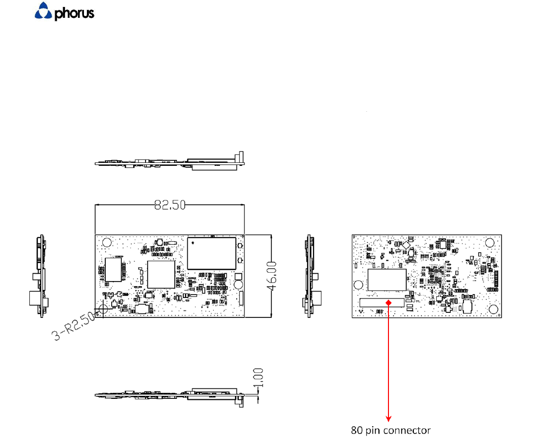
10 Mechanical Interfaces
The Caprica2L is physically mounted to the host with the 80-pin connector and 3 mounting fasteners.
The dimensions for these mounting points, as well as general keep out areas are detailed in Play-Fi
Module Outline and Mounting Drawings
(Caprica_2L_PCB_RevA.DWG,
Caprica_2L_PCB_RevA.pdf).
3D model information is included in both STEP format in Caprica_2L_PCB_RevA.stp
BT Disable
DTS Confidential Revision 1 Page 19 of 24
11 Mechanical Outline
All measurements in millimeters
DTS Confidential Revision 1 Page 20 of 24

DTS Confidential Revision 1 Page 21 of 24
12 Certification Requirements
12.1 User Interface
12.1.1 User Input
The device shall have the following user inputs:
R
equi
r
ed
Feature Implementation
R
equi
r
ement Additional Notes
Volume Up
Confirm 30 volume states can be
accessed via all user interface
methods
These apply to hardware
and application interfaces
Volume
Down
Confirm 30 volume states can be
accessed via all user interface
methods.
Mute1 Must return to the “FF” as a mute
state.
Wi-Fi Set-Up
If a separate WiFi set up button is
used (as opposed to using Factory
Reset) the button must support WiFi
Setup and WPS modes
(WPS mode requires the Wi-Fi setup
button.
An indicator (LED) must be
used to reflect WiFi state.
Factory
Reset
A
single use
r
accessible button shall
provide the factory reset feature.
This shall return all other system
functions to the factory new state,
as well as cycling power.
Can provide WiFi
reset functionality if
required.
Power Provides a user command to turn
the unit from off state to on state
and vice versa.
USB Type A
Plug Type A plug is used for Caprica
Firmware update, using a USB
memory “stick” type device
1 A mute button is option on the industrial design. If it is not included the simultaneous press of volume
up and volume down will operate the mute function.
DTS Confidential Revision 1 Page 22 of 24
12.1.2 Play-Fi to other System Controls
Play-Fi module to system controls:
Criteria Implementation
Requirement Notes
Re-Start after USB update Device restarts as
expected after USB
update of Caprica
Reboot all
The unit cycles
power in the same
manner as a user
commanded power
cycle.
12.1.3 Visual Feedback
The device shall have visual indicators for Wi-Fi Set-Up, Bluetooth Set-Up (if included), and
Mute.
A WiFi light shall indicate the following states:
R
equi
r
ed
Feature Implementation
Requirement Notes
Wi-Fi Set-up
mode Pulsing Blink Ramp from Off to On for 750 msec,
Ramp On to Off for 750 msec
WPS Mode Double Blink On for 100 msec, Off for 100
msec, On for 100 msec, Off for
750, repeat
Connected,
Searching Blinking 250 msec on, 250 msec off
Connected Solid (LED on)
Powering Down Blinking
There shall be a visual way the user can recognize the device is in a Mute state:
Required Feature Implementation
Requirement
Notes
Result
Mute Visual Feedback
Provide a visual
feedback to user
indicating mute
state
BT Disable
DTS Confidential Revision 1 Page 23 of 24
12.1.4 Audible Feedback
The system shall provide the following audible feedback to the user as noted:
Required Feature Implementation
Requirement Notes
Wi-Fi set-up mode is active
Each feature requires
unique audible
feedback which can
be a combination of
audio cues
WPS mode is active
WPS set-up mode is no longer
active
Reset initiated
Factory reset initiated
12.2 Wi-Fi Performance
The Play-Fi module requires a minimum level of Wi-Fi performance.
:
Functional Criteria Implementation
Requirement Notes
WiFi Performance at -72 dBm
RSSI
Validates UDP
performance, transfer
90% of 1 second
samples at 5.5 Mbps
12.3 Branding Requirements
12.3.1 Product Industrial Design
The Play-Fi logo shall be visible to the end consumer. These requirements are
documented in the Play-Fi Branding Guidelines
Criteria Implementation
Requirement Notes
Play-Fi Logo meets
requirements
12.3.2 Product Packaging
The Play-Fi logo shall be printed on the product's packaging in close proximity to other
wireless certification logos (i.e. Bluetooth, Wi-Fi, etc.). If the packaging is full color then
the full color version of the logo shall be used, otherwise the monochromatic version
shall be used.
Packaging requirements:
C
r
ite
r
ia Inspection
R
esults Notes
Play-Fi is Logo properly placed
Play-Fi is Logo properly sized
Play-Fi is Logo colored properly
BT Disable
DTS Confidential Revision 1 Page 24 of 24
12.3.3 Module Identification
The Wi-Fi MAC ID of Play-Fi Module shall be displayed somewhere on the product.
Criteria Implementation Requirement Notes
Wi-Fi Mac ID is displayed on
product
MAC ID displayed on product
matches MAC ID of Play-Fi
module inside product.
13 MCU Controlled Audio Feedbacks
Caprica is not involved in producing audio feedbacks for any of below mentioned cases.
Power ON
Bluetooth connect/disconnect
Factory reset
MCU sends commands to the DSP to render stored sounds in these 3 cases.
When the device is put in WPS/Access point modes, MCU informs the Caprica of the event.
Caprica then informs MCU to send commands to the DSP to render adequate sound for the event.
BT Disable
FCCWarning
Informationtouser
Anychangesormodificationsnotexpresslyapprovedbythepartyresponsiblefor
compliancecouldvoidyourauthoritytooperatetheequipment.
ThisequipmenthasbeentestedandfoundtocomplywiththelimitsforaClassB
digitaldevice,pursuanttopart15oftheFCCRules.Theselimitsaredesignedto
providereasonableprotectionagainstharmfulinterferenceinaresidential
installation.Thisequipmentgenerates,usesandcanradiateradiofrequencyenergy
and,ifnotinstalledandusedinaccordancewiththeinstructions,maycauseharmful
interferencetoradiocommunications.However,thereisnoguaranteethat
interferencewillnotoccurinaparticularinstallation.Ifthisequipmentdoescause
harmfulinterferencetoradioortelevisionreception,whichcanbedeterminedby
turningtheequipmentoffandon,theuserisencouragedtotrytocorrectthe
interferencebyoneormoreofthefollowingmeasures:
—Reorientorrelocatethereceivingantenna.
—Increasetheseparationbetweentheequipmentandreceiver.
—Connecttheequipmentintoanoutletonacircuitdifferentfromthattowhichthe
receiverisconnected.
—Consultthedealeroranexperiencedradio/TVtechnicianforhelp.
Labellingrequirements
ThisdevicecomplieswithPart15oftheFCCRules.Operationissubjecttothe
followingtwoconditions:
(1) thisdevicemaynotcauseharmfulinterferenceand(2)thisdevicemustaccept
anyinterferencereceived,includinginterferencethatmaycauseundesired
operation.
RFRadiationExposureStatement:
1.ThisTransmittermustnotbecolocatedoroperatinginconjunctionwithanyother
antennaortransmitter.
2.ThisequipmentcomplieswithFCCRFradiationexposurelimitssetforthforan
uncontrolledenvironment.Thisequipmentshouldbeinstalledandoperatedwitha
minimumdistanceof20centimetersbetweentheradiatorandyour
body.
ICWarning
ThisdevicecomplieswithIndustryCanadalicense‐exemptRSSstandard(s).Operation
issubjecttothefollowingtwoconditions:(1)thisdevicemaynotcauseinterference,
and(2)thisdevicemustacceptanyinterference,includinginterferencethatmay
causeundesiredoperationofthedevice.
LeprésentappareilestconformeauxCNRd'IndustrieCanadaapplicablesaux
appareilsradioexemptsdelicence.L'exploitationestautoriséeauxdeuxconditions
suivantes:(1)l'appareilnedoitpasproduiredebrouillage,et(2)l'utilisateurde
l'appareildoitacceptertoutbrouillageradioélectriquesubi,mêmesilebrouillageest
susceptibled'encompromettrelefonctionnement.
*Thedevicefortheband5150‐5250MHzisonlyforindooruse.
OEMStatement:
LabellingRequirementsfortheHostdevice
Thehostdeviceshallbeproperlylabelledtoidentifythemoduleswithinthehost
device.Thecertificationlabelofthemoduleshallbeclearlyvisibleatalltimeswhen
installedinthehostdevice,otherwisethehostdevicemustbelabelledtodisplaythe
FCCIDandICofthemodule,precededbythewords"Containstransmittermodule",
ortheword"Contains",orsimilarwordingexpressingthesamemeaning,asfollows:
ContainsFCCID:2AAWQ‐CAPRICA2L
ContainsIC:11138A‐CAPRICA2L
ThismoduleisintendedforOEMintegrator.TheOEMintegratorisstillresponsible
fortheFCCcompliancerequirementoftheendproductwhichintegratesthis
module.
20cmminimumdistancehastobeabletobemaintainedbetweentheantennaand
theusersforthehostthismoduleisintegratedinto.Undersuchconfiguration,the
FCCradiationexposurelimitssetforthforanpopulation/uncontrolledenvironment
canbesatisfied.