Phychips PRM90U10A UHF RFID READER HYBRID MODULE User Manual User s Menuals x
Phychips Inc. UHF RFID READER HYBRID MODULE User s Menuals x
UserManual.wiki
>
Phychips
>
PRM90U10A User Manual
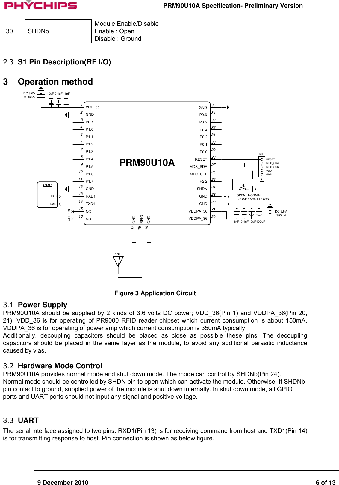
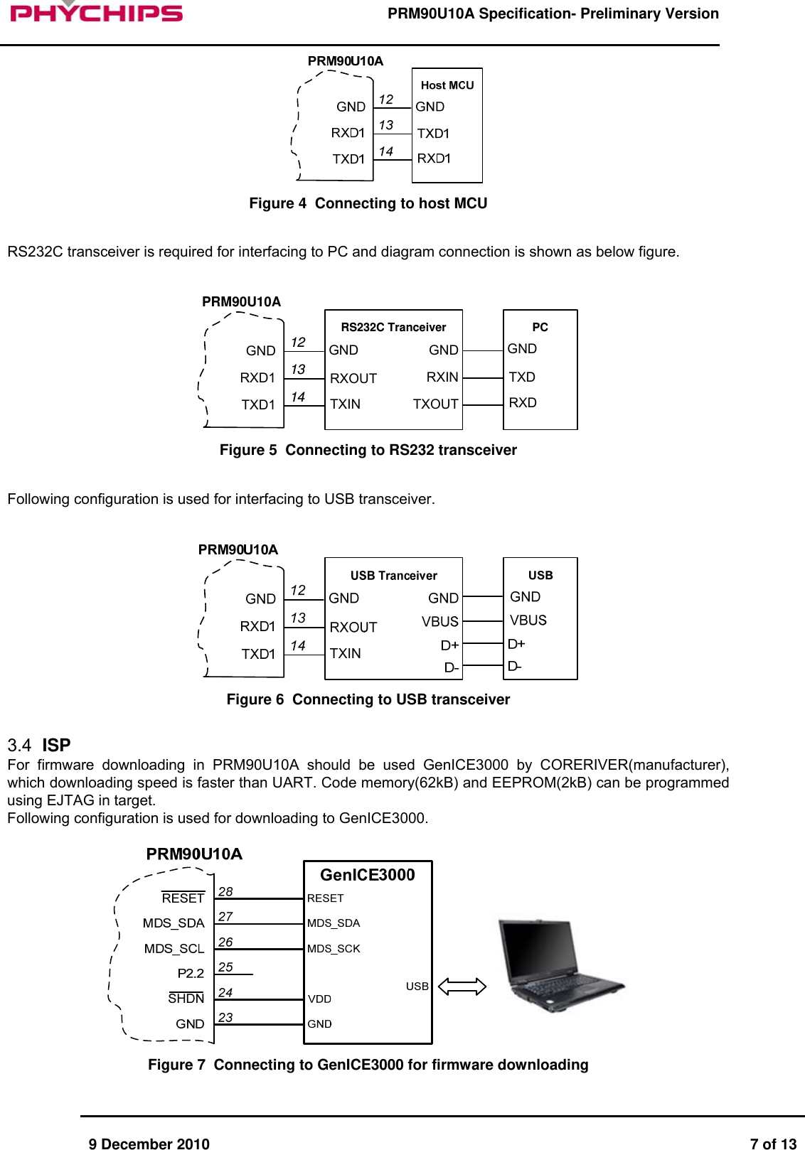
USERS MANUAL
Navigation menu
Upload a User Manual
Namespaces
Wiki Guide
HTML
PDF
Info
Views
User Manual
Discussion / Help
Navigation