Pilz and KG IDN01 InduraNET p, wireless base station User Manual ba pssu wb s idn
Pilz GmbH & Co. KG InduraNET p, wireless base station ba pssu wb s idn
UserManual.wiki
>
Pilz and KG
>
IDN01 User Manual
User Manual
Navigation menu
Upload a User Manual
Namespaces
Wiki Guide
HTML
PDF
Info
Views
User Manual
Discussion / Help
Navigation
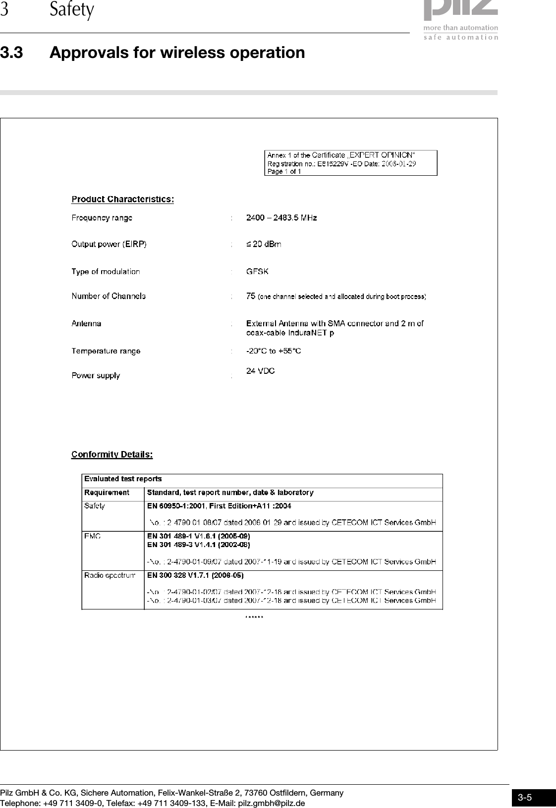
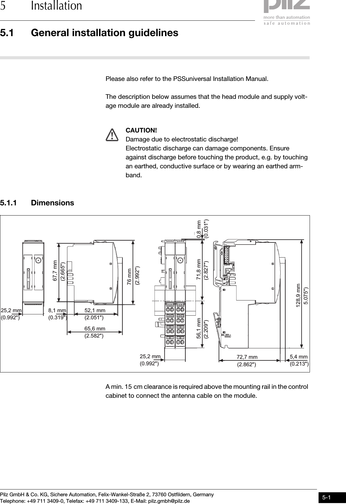
![Pilz GmbH & Co. KG, Sichere Automation, Felix-Wankel-Straße 2, 73760 Ostfildern, GermanyTelephone: +49 711 3409-0, Telefax: +49 711 3409-133, E-Mail: pilz.gmbh@pilz.de 5-35.2 Install base station5 Installation5.2Install base station5200Install base station5-The base station always provides the termination for a PSSuniversal system. No further modules may be positioned to the right of the base station.Prerequisite: `The head module must be installed.`A base module for a supply voltage module is always connected to the right of the head module.Please note:`For mechanical reasons it is not possible to mix base modules with screw terminals and base modules with cage clamp terminals.`All contacts should be protected from contamination.`The mechanics of the base modules are designed for 50 plug in/out cycles.Procedure:`We recommend that you wire up the base modules before inserting the electronic modules.`Slot the groove on the base module on to the mounting rail from below [1].`Push the base module back [2] until you hear it lock into position.`On the mounting rail, slide the base module to the left until you hear the two lateral mounting hooks on the adjacent module lock into posi-tion [3].](https://usermanual.wiki/Pilz-and-KG/IDN01/User-Guide-958942-Page-29.png)
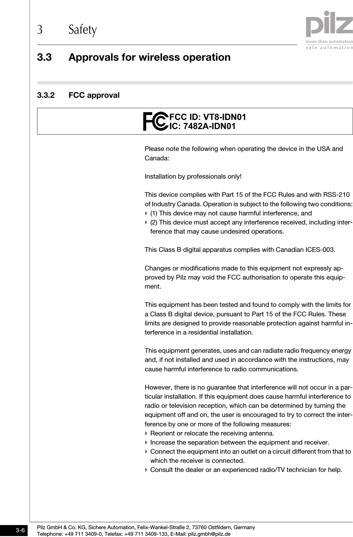
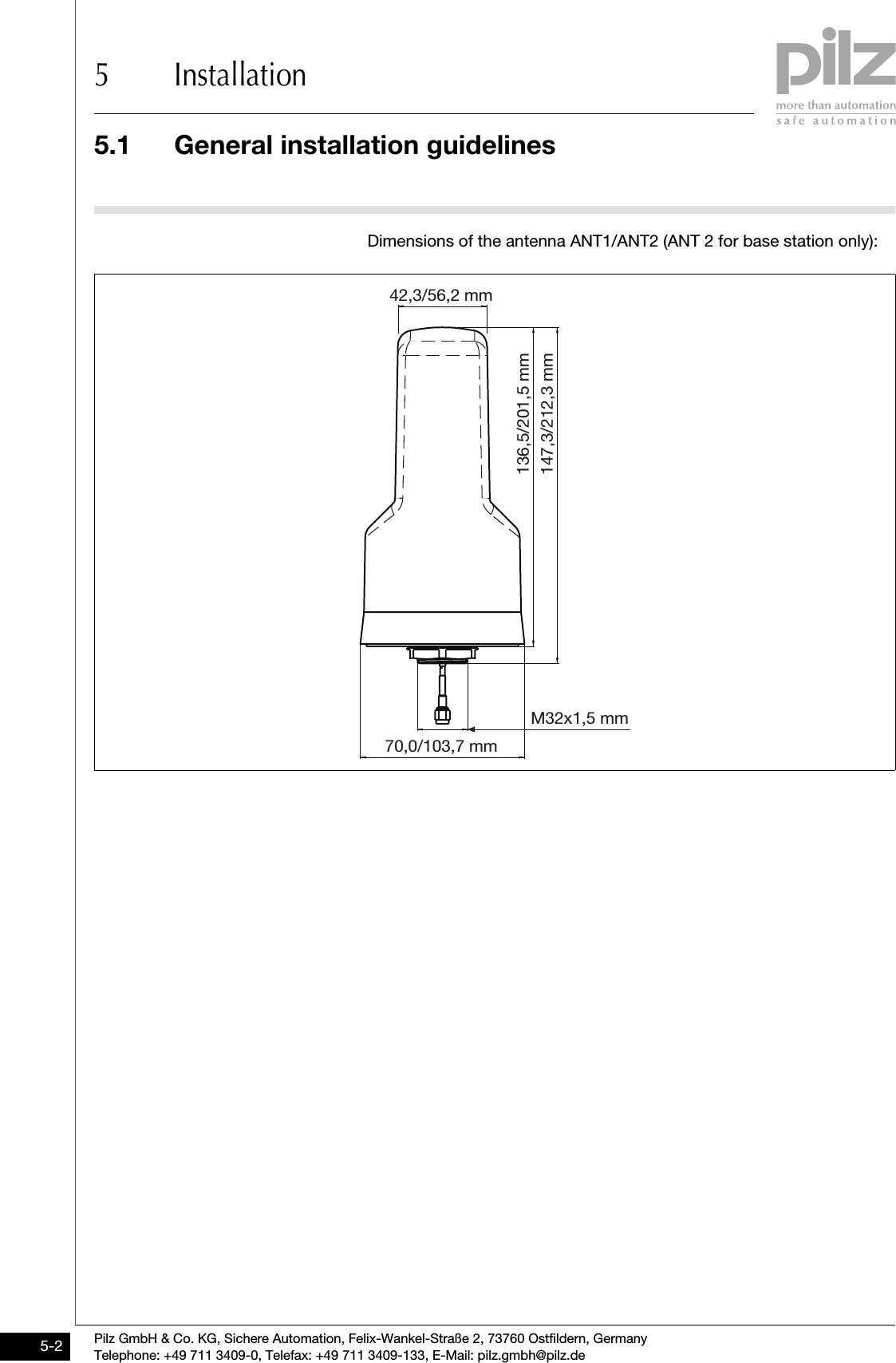
![5.2 Install base station5 InstallationPilz GmbH & Co. KG, Sichere Automation, Felix-Wankel-Straße 2, 73760 Ostfildern, GermanyTelephone: +49 711 3409-0, Telefax: +49 711 3409-133, E-Mail: pilz.gmbh@pilz.de5-4Schematic representation:[2][1][3]](https://usermanual.wiki/Pilz-and-KG/IDN01/User-Guide-958942-Page-30.png)
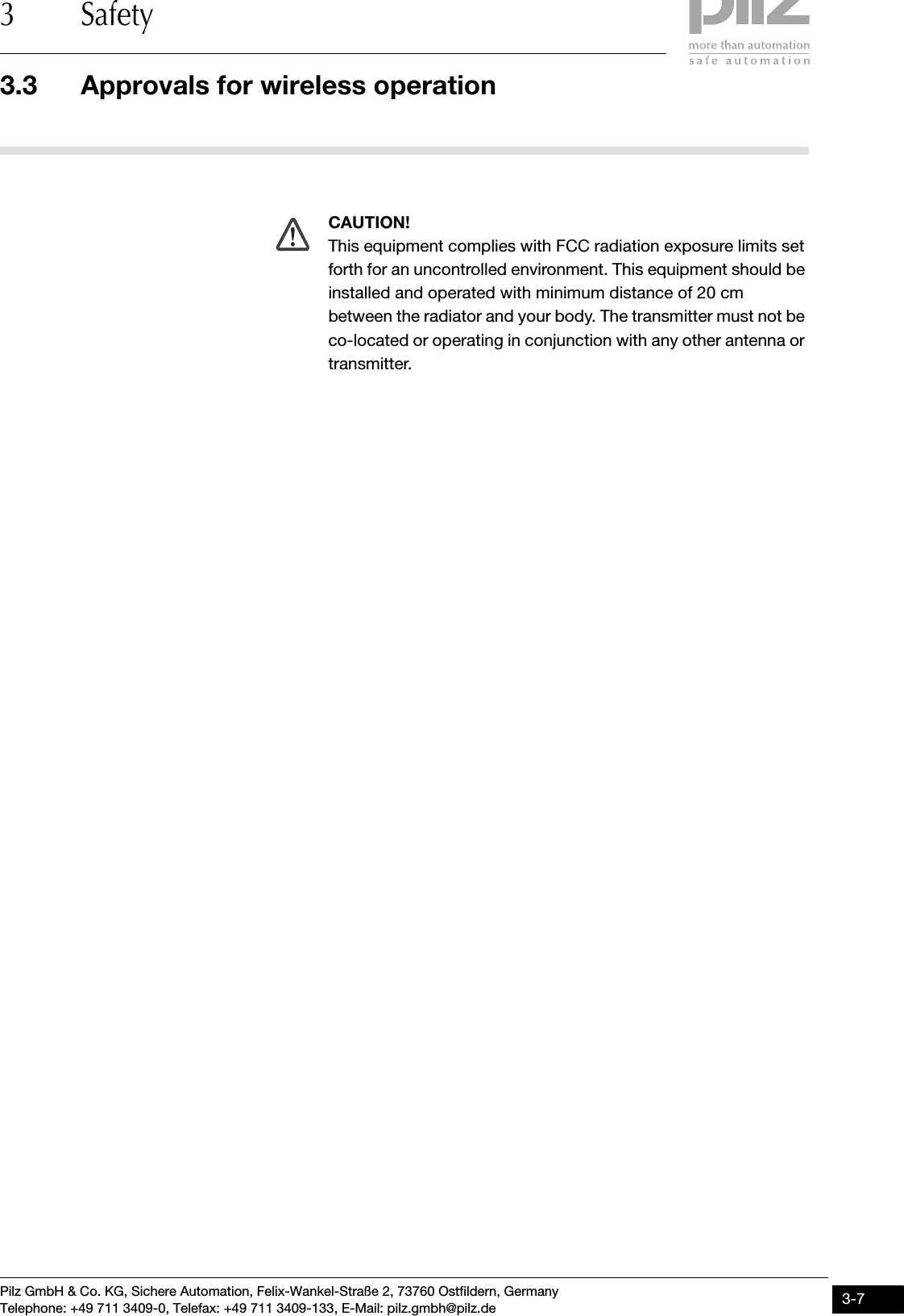
![Pilz GmbH & Co. KG, Sichere Automation, Felix-Wankel-Straße 2, 73760 Ostfildern, GermanyTelephone: +49 711 3409-0, Telefax: +49 711 3409-133, E-Mail: pilz.gmbh@pilz.de 5-55.3 Inserting and removing an electronic module5 Installation5.3Inserting and removing an electronic module5300Inserting and removing an electronic module5-Please note:`Only insert on to base modules that are already installed.`Preferably these base modules should be ready wired.`Electronic modules with outputs may only be inserted and removed when the load is switched off. Unforeseeable error reactions may be triggered if modules are inserted and removed under load.`When an electronic module is plugged into a base module for the first time, one part of the coding element remains on the electronic module, while its counterpart is fixed on to the base module. This is how the base module is coded.`The mechanics of the electronic modules are designed for 50 plug in/out cycles.5.3.1 Inserting an electronic moduleInserting an electronic module5-Procedure:`The electronic module must audibly lock into position [1].`Mark the electronic module using the labelling strips [2].Schematic representation:[2][1][1]](https://usermanual.wiki/Pilz-and-KG/IDN01/User-Guide-958942-Page-31.png)
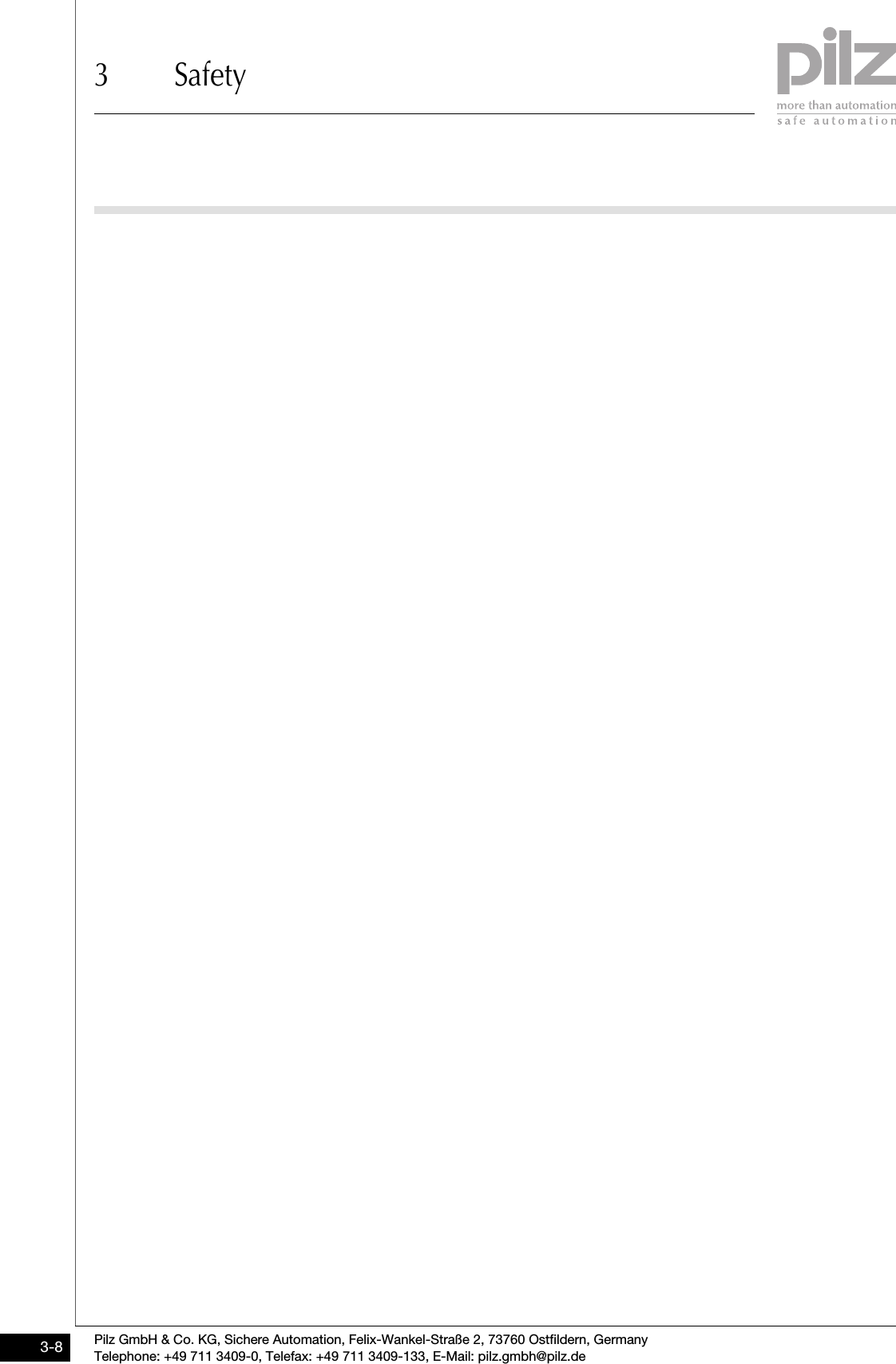
![5.3 Inserting and removing an electronic module5 InstallationPilz GmbH & Co. KG, Sichere Automation, Felix-Wankel-Straße 2, 73760 Ostfildern, GermanyTelephone: +49 711 3409-0, Telefax: +49 711 3409-133, E-Mail: pilz.gmbh@pilz.de5-65.3.2 Removing an electronic moduleRemoving an electronic module5-Procedure:`Press the locking mechanisms [1] together simultaneously.`Pull out the electronic module [2].Schematic representation:5.3.3 Changing an electronic module during operationChanging an electronic module during operation5-INFORMATIONAfter a module has been changed during operation, in some cir-cumstances the remote stations may no longer be detected cor-rectly. Only change the module in the off state![1][2][1]](https://usermanual.wiki/Pilz-and-KG/IDN01/User-Guide-958942-Page-32.png)
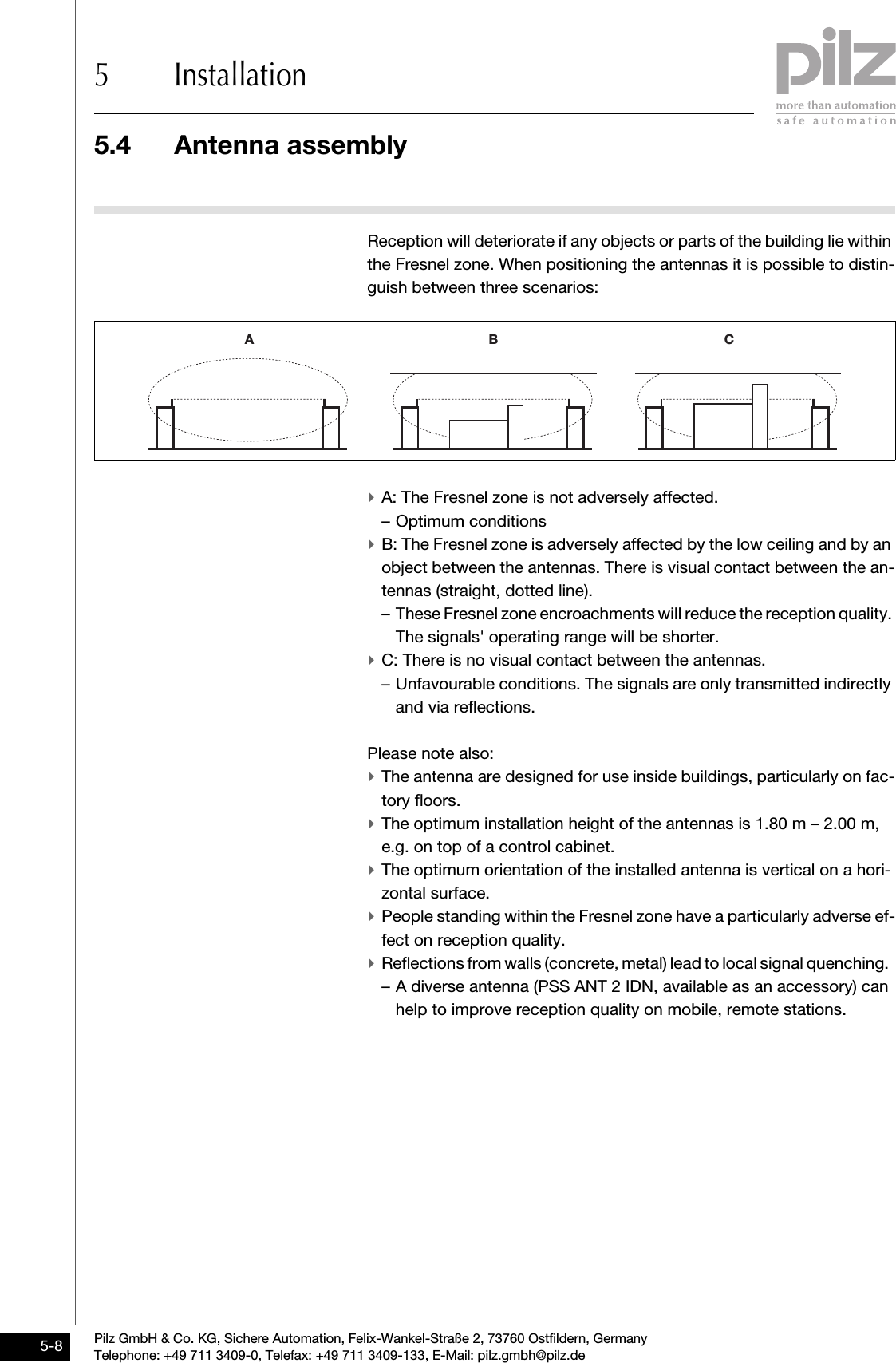
![Pilz GmbH & Co. KG, Sichere Automation, Felix-Wankel-Straße 2, 73760 Ostfildern, GermanyTelephone: +49 711 3409-0, Telefax: +49 711 3409-133, E-Mail: pilz.gmbh@pilz.de 5-75.4 Antenna assembly5 Installation5.4Antenna assembly5400Antenna assembly5-As with all radio signals, the InduraNET p signals will mainly propagate in the first Fresnel zone. The Fresnel zone is a spheroid, in whose focus the antennas are located.Schematic representation:The size of the Fresnel zone depends on the wavelength of the radio sig-nal and the distance of the antennas.At 2.4 GHz, approximate values for the Fresnel zone's radius R in rela-tion to antenna distance d: d [m]5 8 121620305075100R [m] 0,4 0,5 0,6 0,7 0,8 0,9 1,3 1,5 1,8dR](https://usermanual.wiki/Pilz-and-KG/IDN01/User-Guide-958942-Page-33.png)
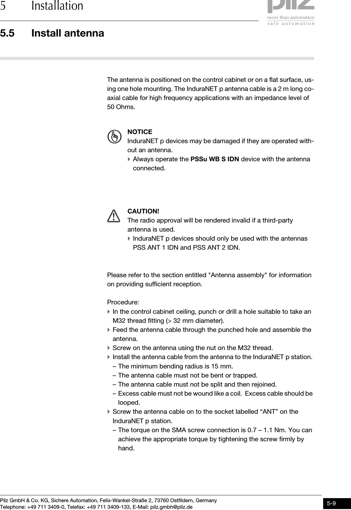
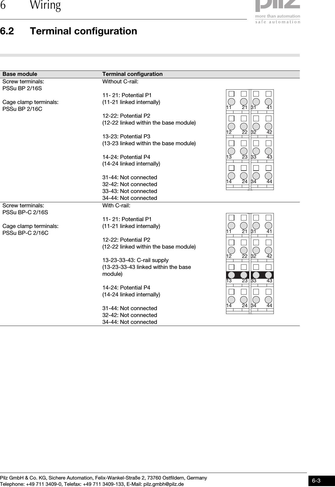
![Pilz GmbH & Co. KG, Sichere Automation, Felix-Wankel-Straße 2, 73760 Ostfildern, GermanyTelephone: +49 711 3409-0, Telefax: +49 711 3409-133, E-Mail: pilz.gmbh@pilz.de 6-16.1 General wiring guidelines6 Wiring66000WiringWiring6-6.1General wiring guidelines6100General wiring guidelines6-Please note:`The maximum current load for the periphery supply on the module bus is 10 A.`The external power supplies must comply with the current applicable standard EN 60950-1, EN 61140, EN 50178 or EN 61558-1.`Use copper wiring.6.1.1 Mechanical connection of the base modulesMechanical connection of the base modules6-Procedure:`Use a flat blade screwdriver (DIN 5264-A)!`Strip the wire back 8 mm.`If necessary, label the connection level with a colour marker [3].`Base module with screw terminals:– Use a screwdriver to loosen the screw on the screw terminal [1]– Insert the stripped cable into the round fixing hole [2], as far as it will go.– Tighten up the screw on the screw terminal.– Check that the cable is firmly seated.`Base module with cage clamp terminals:– Insert the screwdriver [4] into the square hole [1].– Insert the stripped cable into the round fixing hole [2], as far as it will go [5].– Pull out the screwdriver [6].– Check that the cable is firmly seated.DIN 5264-A2111[1][3][2]](https://usermanual.wiki/Pilz-and-KG/IDN01/User-Guide-958942-Page-37.png)
![6.1 General wiring guidelines6 WiringPilz GmbH & Co. KG, Sichere Automation, Felix-Wankel-Straße 2, 73760 Ostfildern, GermanyTelephone: +49 711 3409-0, Telefax: +49 711 3409-133, E-Mail: pilz.gmbh@pilz.de6-2Please note:`The minimum cable cross section for field connection terminals on the base modules is 0.14 mm2 (AWG26)`The maximum cable cross section for field connection terminals is: – Digital inputs: 1.5 mm2 (AWG16)– Digital outputs: 2.0 mm2 (AWG14)– Inputs/outputs on the counter modules: 1.5 mm2 (AWG16)– Analogue inputs/outputs: 1.5 mm2 (AWG16)– Communication cables: 1.5 mm2 (AWG16)– Test pulse outputs: 1.5 mm2 (AWG16)– Power supply: 2.5 mm2 (AWG12)– Functional earth: 2.5 mm2 (AWG12)`On base modules with screw terminals: – If you use a multi-strand cable to connect the I/Os, it is recommend-ed that you use ferrules conforming to Parts 1 and 2 of DIN 46228, 0.14 ... 1.5 mm2, Form A or C, although this is not essential. To crimp the ferrules you can use crimp pliers (crimp form A or C) conforming to EN 60947-1, such as the PZ 1.5 or PZ 6.5 from Weidmüller, for example.`Use copper wiring.[4][5][6]](https://usermanual.wiki/Pilz-and-KG/IDN01/User-Guide-958942-Page-38.png)