Pilz and KG IDN01 InduraNET p, wireless base station User Manual ba pssu wb s idn
Pilz GmbH & Co. KG InduraNET p, wireless base station ba pssu wb s idn
User Manual

Programmable control systems PSS®
PSSu WB S IDN
Operating Manual – Item No. 21 835-01

All rights to this documentation are reserved by Pilz GmbH & Co. KG. Copies may be made
for internal purposes.
Suggestions and comments for improving this documentation will be gratefully received.
Pilz
®
, PIT
®
, PMI
®
, PNOZ
®
, Primo
®
, PSEN
®
, PSS
®
, PVIS
®
, SafetyBUS p
®
, SafetyEYE
®
,
SafetyNET p
®
, the spirit of safety
®
are registered and protected trademarks of
Pilz GmbH & Co. KG in some countries.
Pilz GmbH & Co. KG, Sichere Automation, Felix-Wankel-Straße 2, 73760 Ostfildern, Germany
Telephone: +49 711 3409-0, Telefax: +49 711 3409-133, E-Mail: pilz.gmbh@pilz.de 1
Contents
Contents
Contents Page
Chapter 1 Introduction
1.1 Validity of documentation 1-1
1.1.1 Retaining the documentation 1-1
1.2 Overview of documentation 1-2
1.3 Definition of symbols 1-3
Chapter 2 Overview
2.1 Module structure 2-1
2.1.1 Module features 2-2
2.1.2 Features of InduraNET p 2-2
2.2 Front view 2-4
Chapter 3 Safety
3.1 Intended use 3-1
3.2 Safety regulations 3-2
3.2.1 Use of qualified personnel 3-2
3.2.2 Warranty and liability 3-2
3.2.3 Disposal 3-2
3.3 Approvals for wireless operation 3-3
3.3.1 European approval 3-4
3.3.2 FCC approval 3-6
Chapter 4 Function description
4.1 Module features 4-1
4.1.1 Integrated protection mechanisms 4-1
4.1.2 Base station in InduraNET p 4-1
4.2 InduraNET p 4-2
4.3 Chip card 4-3
Chapter 5 Installation
5.1 General installation guidelines 5-1
5.1.1 Dimensions 5-1
5.2 Install base station 5-3
5.3 Inserting and removing an electronic
module
5-5
5.3.1 Inserting an electronic module 5-5
5.3.2 Removing an electronic module 5-6
5.3.3 Changing an electronic module during
operation
5-6
5.4 Antenna assembly 5-7
5.5 Install antenna 5-9
Contents
Pilz GmbH & Co. KG, Sichere Automation, Felix-Wankel-Straße 2, 73760 Ostfildern, Germany
Telephone: +49 711 3409-0, Telefax: +49 711 3409-133, E-Mail: pilz.gmbh@pilz.de
2
Chapter 6 Wiring
6.1 General wiring guidelines 6-1
6.1.1 Mechanical connection of the base
modules
6-1
6.2 Terminal configuration 6-3
Chapter 7 Operation
7.1 Messages 7-1
7.2 Display elements 7-2
7.2.1 Display elements for InduraNET p
diagnostics
7-2
Chapter 8 Technical details
8.1 Technical details 8-1

Pilz GmbH & Co. KG, Sichere Automation, Felix-Wankel-Straße 2, 73760 Ostfildern, Germany
Telephone: +49 711 3409-0, Telefax: +49 711 3409-133, E-Mail: pilz.gmbh@pilz.de 1-1
1.1 Validity of documentation
1 Introduction
11000IntroductionIntroduction1-1.1Validity of documenta tion1100Validity of documenta tion1-
This documentation is valid for the product PSSu WB S IDN. It is valid
until new documentation is published.
This operating manual explains the function and operation of the pro-
grammable safety system, describes the installation and provides
guidelines on how to connect the product PSSu WB S IDN.
Using the product PSSu WB S IDN:
Base station to connect the PSSuniversal system to InduraNET p for
standard data
1.1.1 Retaining the documentation
Retaining the documentation1-
This documentation is intended for instruction and should be retained
for future reference.

1.2 Overview of documentation
1 Introduction
Pilz GmbH & Co. KG, Sichere Automation, Felix-Wankel-Straße 2, 73760 Ostfildern, Germany
Telephone: +49 711 3409-0, Telefax: +49 711 3409-133, E-Mail: pilz.gmbh@pilz.de
1-2
1.2Overview of documentation1200Overview of documentation1-
1 Introduction
The introduction is designed to familiarise you with the contents, struc-
ture and specific order of this manual.
2 Overview
This chapter provides information on the module's most important fea-
tures.
3 Safety
This chapter must be read as it contains important information on in-
tended use.
4 Function Description
This chapter describes the module's individual components.
5 Installation
This chapter explains how to install the module.
6 Wiring
This chapter describes the module's wiring.
7 Operation
This chapter explains the display elements and advises on what to do if
a fault occurs.
8 Technical Details
Pilz GmbH & Co. KG, Sichere Automation, Felix-Wankel-Straße 2, 73760 Ostfildern, Germany
Telephone: +49 711 3409-0, Telefax: +49 711 3409-133, E-Mail: pilz.gmbh@pilz.de 1-3
1.3 Definition of symbols
1 Introduction
1.3Definition of symbols1300Definition of symbols1-
Information in this manual that is of particular importance can be identi-
fied as follows:
DANGER!
This warning must be heeded! It warns of a hazardous situation
that poses an immediate threat of serious injury and death and
indicates preventive measures that can be taken.
WARNING!
This warning must be heeded! It warns of a hazardous situation
that could lead to serious injury and death and indicates preven-
tive measures that can be taken.
CAUTION!
This refers to a hazard that can lead to a less serious or minor
injury plus material damage, and also provides information on
preventive measures that can be taken.
NOTICE
This describes a situation in which the unit(s) could be damaged
and also provides information on preventive measures that can
be taken.
INFORMATION
This gives advice on applications and provides information on
special features, as well as highlighting areas within the text that
are of particular importance.

1 Introduction
Pilz GmbH & Co. KG, Sichere Automation, Felix-Wankel-Straße 2, 73760 Ostfildern, Germany
Telephone: +49 711 3409-0, Telefax: +49 711 3409-133, E-Mail: pilz.gmbh@pilz.de
1-4

Pilz GmbH & Co. KG, Sichere Automation, Felix-Wankel-Straße 2, 73760 Ostfildern, Germany
Telephone: +49 711 3409-0, Telefax: +49 711 3409-133, E-Mail: pilz.gmbh@pilz.de 2-1
2.1 Module structure
2 Overview
22000OverviewOverview2-2.1Module structure2100Module structure2-
A module consists of
`Electronic module and
`Base module with
– Screw terminals or
– Cage clamp terminals
The base modules are the carrier units for the electronic modules and
are used to connect the field wiring. The electronic modules are inserted
on to the base modules and determine the module's function.
Details of the base modules that can be used are available in the
“Wiring” chapter.
The PSSu WB S IDN module is supplied with a chip card for storing the
configuration data. Additional chip cards are available as an accessory.
An antenna is required in order to operate the module. Two antenna
types are available:
`For remote and base stations:
PSS ANT 1 IDN
`For base stations only:
PSS ANT 2 IDN
The antenna is supplied with an SMA antenna cable which is 2 m long
and has an impedance level of 50 Ohm. A suitable 2 m long extension
cable is available as an accessory.
The chip card reader SCR 335 USB with USB cable is available as an
accessory.
CAUTION!
The radio approval will be rendered invalid if a third-party
antenna is used.
`InduraNET p devices should only be used with the antennas
PSS ANT 1 IDN and PSS ANT 2 IDN.

2.1 Module structure
2 Overview
Pilz GmbH & Co. KG, Sichere Automation, Felix-Wankel-Straße 2, 73760 Ostfildern, Germany
Telephone: +49 711 3409-0, Telefax: +49 711 3409-133, E-Mail: pilz.gmbh@pilz.de
2-2
2.1.1 Module features
Module features2-
The module has the following features:
`The module terminates a PSSu system and extends the ST data bus
across an InduraNET p radio link.
`As a base station the module supports up to four remote stations
PSSu WR S IDN
`Antenna connection for InduraNET p
`The module provides connections for external supplies. The external
supplies are galvanically isolated from the module bus supplies.
`LEDs for:
–InduraNET p status per remote station
–Module error
2.1.2 Features of InduraNET p
Features of InduraNET p2-
InduraNET p enables wireless communication on the PSSuniversal.
Data from the standard section is transmitted via radio instead of the
module bus. Wireless communication via InduraNET p does not need to
be considered in the user program.
The module bus cycle is recreated in the remote system. This will in-
crease the input/output reaction times of a remote system.
Each InduraNET p device is given an ID, which ensures that all subscrib-
ers are uniquely identified. Up to ten InduraNET p networks can coexist
within one environment. All the settings for wireless communication are
stored within the module on a chip card, which is written via a chip card
reader.
Pilz GmbH & Co. KG, Sichere Automation, Felix-Wankel-Straße 2, 73760 Ostfildern, Germany
Telephone: +49 711 3409-0, Telefax: +49 711 3409-133, E-Mail: pilz.gmbh@pilz.de 2-3
2.1 Module structure
2 Overview
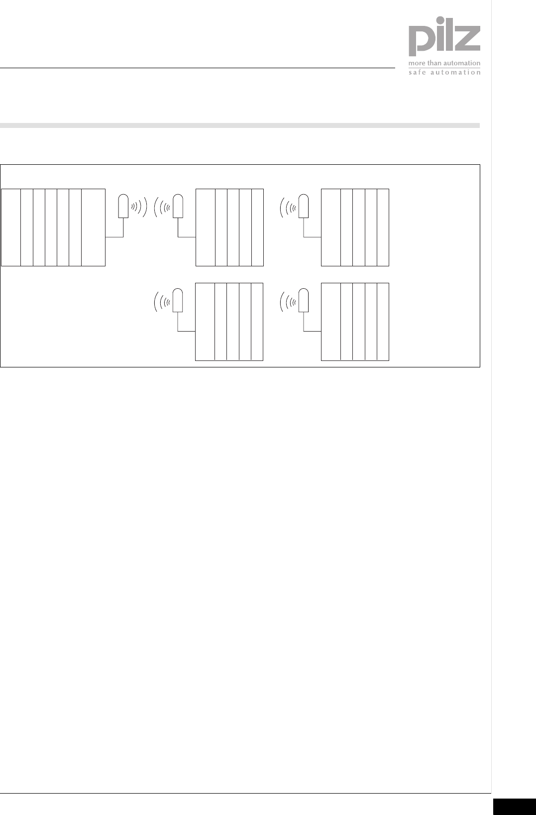
Schematic representation of InduraNET p
Head module (FS/ST)
I/O module (FS/ST)
I/O module (FS/ST)
I/O module (FS/ST)
I/O module (FS/ST)
IDN base station
ANT
Supply
I/O module (ST)
IDN remote station
ANT
I/O module (ST)
I/O module (ST)
I/O module (ST)
I/O module (ST)
IDN remote station
ANT
I/O module (ST)
I/O module (ST)
I/O module (ST)
I/O module (ST)
IDN remote station
ANT
I/O module (ST)
I/O module (ST)
I/O module (ST)
I/O module (ST)
IDN remote station
ANT
I/O module (ST)
I/O module (ST)
I/O module (ST)
Base system Up to 4 remote systems
InduraNET p
2.2 Front view
2 Overview
Pilz GmbH & Co. KG, Sichere Automation, Felix-Wankel-Straße 2, 73760 Ostfildern, Germany
Telephone: +49 711 3409-0, Telefax: +49 711 3409-133, E-Mail: pilz.gmbh@pilz.de
2-4
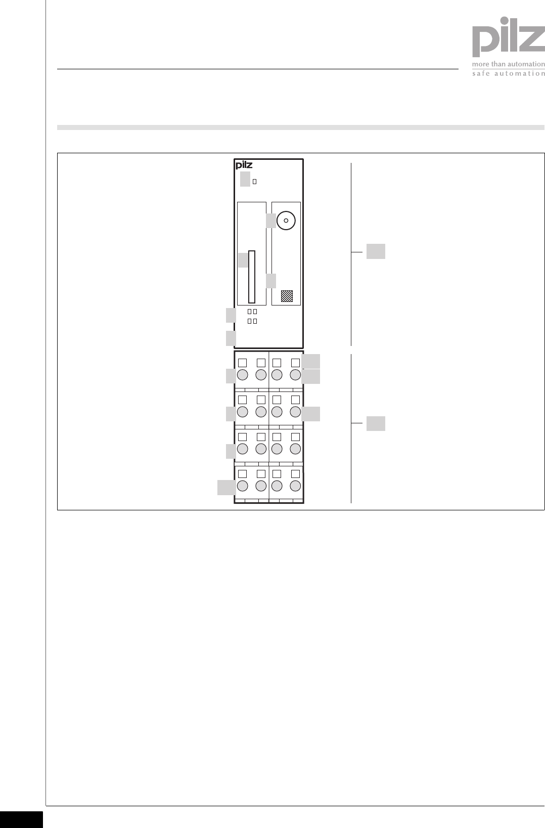
2.2Front view2200Front view2-
Key:
`A: Electronic module PSSu WB S IDN
`B: Base module
`1: LED for module diagnostics
`2: Chip card slot
`3: Antenna connection (SMA)
`4: Labelling strip with:
– Name of electronic module
–Order number
– Serial number
– Hardware version number
–2D code
`5: LEDs for the status of the remote stations
`6: Name of electronic module
`7: Connection level 1
`8: Connection level 2
`9: Connection level 3
`10: Connection level 4
2111
2212
2414
4131
4232
4434
2313 4333
Err
PSSu
WB S IDN
312095
000000
000
R1
R2
R3
R4
CHIP ANT
PSSu
WB S IDN
13
1
3
7
8
9
2A
B
4
12
11
5
6
10

Pilz GmbH & Co. KG, Sichere Automation, Felix-Wankel-Straße 2, 73760 Ostfildern, Germany
Telephone: +49 711 3409-0, Telefax: +49 711 3409-133, E-Mail: pilz.gmbh@pilz.de 2-5
2.2 Front view
2 Overview
`11: Square mounting holes (connection levels 1, 2, 3 and 4)
– With screw to loosen/tighten the screw terminal on base modules
with screw terminals
– With mechanism to operate the cage clamp on base modules with
cage clamp terminals
`12: Round connection holes (connection levels 1, 2, 3 and 4) for con-
necting the cables
`13: Mounting slot for colour marker to label the connection level (con-
nection levels 1, 2, 3 and 4)

2 Overview
Pilz GmbH & Co. KG, Sichere Automation, Felix-Wankel-Straße 2, 73760 Ostfildern, Germany
Telephone: +49 711 3409-0, Telefax: +49 711 3409-133, E-Mail: pilz.gmbh@pilz.de
2-6

Pilz GmbH & Co. KG, Sichere Automation, Felix-Wankel-Straße 2, 73760 Ostfildern, Germany
Telephone: +49 711 3409-0, Telefax: +49 711 3409-133, E-Mail: pilz.gmbh@pilz.de 3-1
3.1 Intended use
3 Safety
33000SafetySafety3-3.1Intended use3100Intended use3-
The module may be used as a base station in InduraNET p, for the wire-
less communication of ST data. It can be operated with up to four re-
mote stations of type PSSu WR S IDN.
The module may be used to feed and extract external supplies to and
from the connection terminals.
Intended use includes making the electrical installation EMC-compliant.
Please refer to the guidelines stated in the “PSSuniversal Installation
Manual”. The module is designed for use in an industrial environment. It
is not suitable for use in a domestic environment, as this can lead to in-
terference.
The following is deemed improper use in particular:
`Any component, technical or electrical modification to the module
`Use of the module outside the areas described in this manual
`Use of the module outside the technical details (see chapter entitled
“Technical Details”)
The PSSu WB S IDN module may be used in conjunction with the fol-
lowing base modules:
`PSSu BP 2/16S
`PSSu BP 2/16C
`PSSu BP-C 2/16S
`PSSu BP-C 2/16C
INFORMATION
The module is supported by the PSSuniversal Configurator and
the PSSuniversal Assistant from Version 1.5.
The module is supported by PSSuniversal head modules from
ST Firmware Version 12.

3.2 Safety regulations
3 Safety
Pilz GmbH & Co. KG, Sichere Automation, Felix-Wankel-Straße 2, 73760 Ostfildern, Germany
Telephone: +49 711 3409-0, Telefax: +49 711 3409-133, E-Mail: pilz.gmbh@pilz.de
3-2
3.2Safety regulations3200Safety regulations3-
3.2.1 Use of qualified personnel
Use of qualified personnel3-
The products may only be assembled, installed, programmed, commis-
sioned, operated, maintained and decomissioned by qualified person-
nel. Qualified personnel are people who, because they are:
`Qualified electrical engineers or
`Have received training from qualified electrical engineers
are suitably experienced to operate devices, systems, plant and ma-
chinery in accordance with the general standards and guidelines for
safety technology.
It is the company's responsibility only to employ personnel who:
`Are familiar with the basic regulations concerning health and safety /
accident prevention
`Have read and understood the safety guidelines given in this descrip-
tion
`Have a good knowledge of the generic and specialist standards appli-
cable to the specific application.
3.2.2 Warranty and liability
Warranty and liability3-
All claims to warranty and liability will be rendered invalid if, among other
things:
`The product was used contrary to the purpose for which it is intended
`Damage can be attributed to not having followed the guidelines in the
manual
`Operating personnel are not suitably qualified
`Any type of modification has been made (e.g. exchanging compo-
nents on the PCB boards, soldering work etc.).
3.2.3 Disposal
Disposal3-
The product must be disposed of properly when it reaches the end of its
service life.

Pilz GmbH & Co. KG, Sichere Automation, Felix-Wankel-Straße 2, 73760 Ostfildern, Germany
Telephone: +49 711 3409-0, Telefax: +49 711 3409-133, E-Mail: pilz.gmbh@pilz.de 3-3
3.3 Approvals for wireless operation
3 Safety
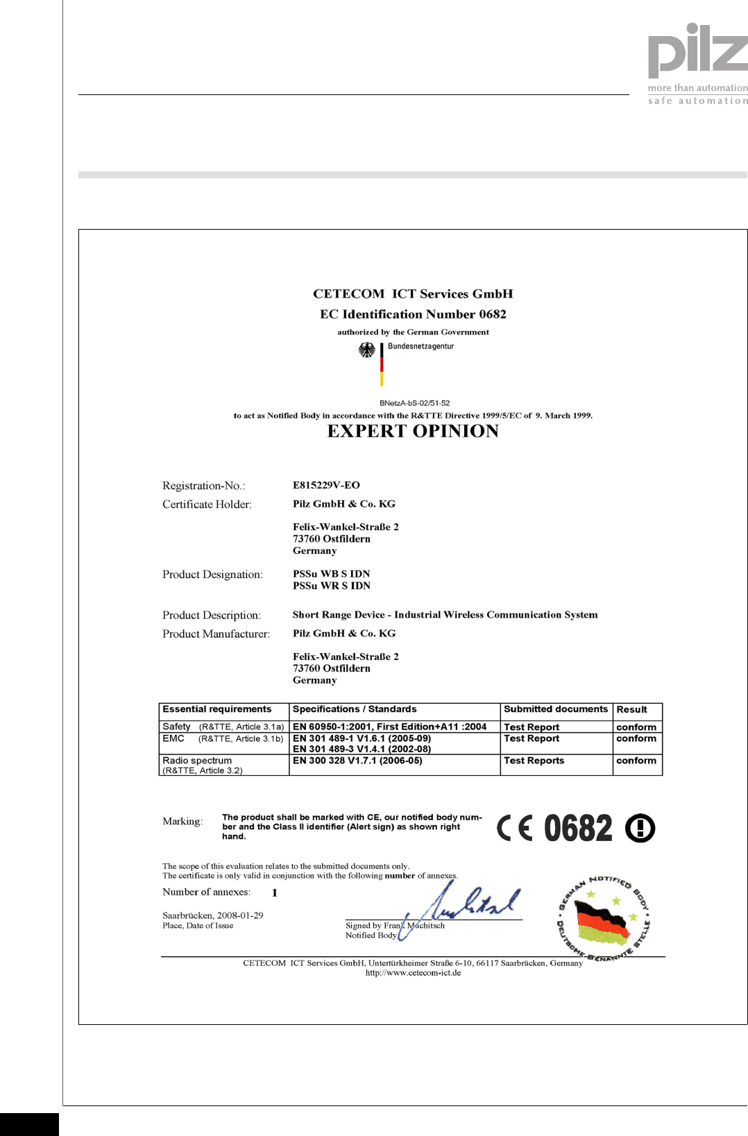
3.3Approvals for wireless operation3300Approvals for wireless operation3-
InduraNET p devices meet the requirements and specifications of the
EU directive 1999/5/EU and may be operated in all European Union
countries with the exception of:
`Hungary, Latvia, Lithuania, Poland, Romania, Slovakia, Slovenia
InduraNET p devices may also be operated in the following countries:
`Norway, Switzerland, Liechtenstein, Iceland
`Japan
`Canada, USA
Other countries: On request
In France, InduraNET p devices may only be operated inside.
Please comply with the provisions of ERC/REC 70-03 Appendix 3 -
National Restrictions (Annex 3 Band A).
Radio approval for the antenna PSS ANT 2 IDN is in progress.
3.3 Approvals for wireless operation
3 Safety
Pilz GmbH & Co. KG, Sichere Automation, Felix-Wankel-Straße 2, 73760 Ostfildern, Germany
Telephone: +49 711 3409-0, Telefax: +49 711 3409-133, E-Mail: pilz.gmbh@pilz.de
3-4
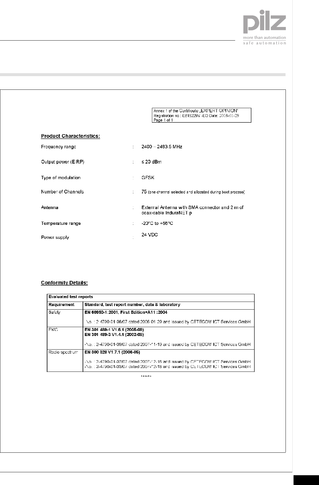
3.3.1 European approval
European approval 3-
Pilz GmbH & Co. KG, Sichere Automation, Felix-Wankel-Straße 2, 73760 Ostfildern, Germany
Telephone: +49 711 3409-0, Telefax: +49 711 3409-133, E-Mail: pilz.gmbh@pilz.de 3-5
3.3 Approvals for wireless operation
3 Safety
3.3 Approvals for wireless operation
3 Safety
Pilz GmbH & Co. KG, Sichere Automation, Felix-Wankel-Straße 2, 73760 Ostfildern, Germany
Telephone: +49 711 3409-0, Telefax: +49 711 3409-133, E-Mail: pilz.gmbh@pilz.de
3-6
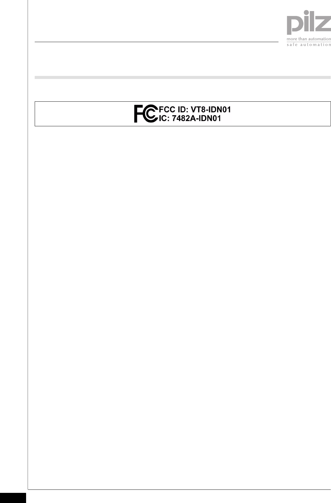
3.3.2 FCC approval
FCC approval3-
Please note the following when operating the device in the USA and
Canada:
Installation by professionals only!
This device complies with Part 15 of the FCC Rules and with RSS-210
of Industry Canada. Operation is subject to the following two conditions:
`(1) This device may not cause harmful interference, and
`(2) This device must accept any interference received, including inter-
ference that may cause undesired operations.
This Class B digital apparatus complies with Canadian ICES-003.
Changes or modifications made to this equipment not expressly ap-
proved by Pilz may void the FCC authorisation to operate this equip-
ment.
This equipment has been tested and found to comply with the limits for
a Class B digital device, pursuant to Part 15 of the FCC Rules. These
limits are designed to provide reasonable protection against harmful in-
terference in a residential installation.
This equipment generates, uses and can radiate radio frequency energy
and, if not installed and used in accordance with the instructions, may
cause harmful interference to radio communications.
However, there is no guarantee that interference will not occur in a par-
ticular installation. If this equipment does cause harmful interference to
radio or television reception, which can be determined by turning the
equipment off and on, the user is encouraged to try to correct the inter-
ference by one or more of the following measures:
`Reorient or relocate the receiving antenna.
`Increase the separation between the equipment and receiver.
`Connect the equipment into an outlet on a circuit different from that to
which the receiver is connected.
`Consult the dealer or an experienced radio/TV technician for help.

Pilz GmbH & Co. KG, Sichere Automation, Felix-Wankel-Straße 2, 73760 Ostfildern, Germany
Telephone: +49 711 3409-0, Telefax: +49 711 3409-133, E-Mail: pilz.gmbh@pilz.de 3-7
3.3 Approvals for wireless operation
3 Safety
CAUTION!
This equipment complies with FCC radiation exposure limits set
forth for an uncontrolled environment. This equipment should be
installed and operated with minimum distance of 20 cm
between the radiator and your body. The transmitter must not be
co-located or operating in conjunction with any other antenna or
transmitter.

3 Safety
Pilz GmbH & Co. KG, Sichere Automation, Felix-Wankel-Straße 2, 73760 Ostfildern, Germany
Telephone: +49 711 3409-0, Telefax: +49 711 3409-133, E-Mail: pilz.gmbh@pilz.de
3-8

Pilz GmbH & Co. KG, Sichere Automation, Felix-Wankel-Straße 2, 73760 Ostfildern, Germany
Telephone: +49 711 3409-0, Telefax: +49 711 3409-133, E-Mail: pilz.gmbh@pilz.de 4-1
4.1 Module features
4 Function description
44000Function descriptionFunction description4-4.1Module features4100Module features4-
4.1.1 Integrated protection mechanisms
Integrated protection mechanisms4-
When the PSSu E F PS1(-T) is used to supply the system, the module
supply is buffered for 20 ms if the supply voltage is interrupted.
The module provides the following diagnostic data:
`Module status
`Module error
4.1.2 Base station in InduraNET p
Base station in InduraNET p4-
The module is a base station in InduraNET p and extends the PSSu
module bus across a radio link. The base station is always the termina-
tion module in a base system. The base station can communicate with
up to four remote stations.
The module provides connections for external supplies.
`The module does not switch the external supplies.
`The external supplies are galvanically isolated from the module bus
supplies and from each other.
`The module has no current limitation on the external supplies.

4.2 InduraNET p
4 Function description
Pilz GmbH & Co. KG, Sichere Automation, Felix-Wankel-Straße 2, 73760 Ostfildern, Germany
Telephone: +49 711 3409-0, Telefax: +49 711 3409-133, E-Mail: pilz.gmbh@pilz.de
4-2
4.2InduraNET p4200InduraNET p4-
Properties of wireless communication
`Frequency range 2.4 GHz ISM band
`Strong immunity to signals from other wireless services
`CFM (Coexistence Frequency Management) guarantees that
InduraNET p devices coexist without problem with other radio-based
systems.
– InduraNET p devices do not use non-overlapping WLAN channels.
– InduraNET p devices do not transmit until they have scanned their
frequency range (Listen before Talk).
– InduraNET p devices switch to free channels in order to avoid colli-
sions.
Properties of the antenna
`The antenna is designed to IP54. It can be installed on a flat surface
using one hole mounting.
`The SMA antenna cable is 2 m long and has an impedance level of
50 Ohm.
`The max. operating range depends heavily on surface reflection and
on the transmissivity of surrounding materials. Approximate guidelines
are:
– 10 m ... 100 m indoors
– 100 m ... 1000 m outdoors
`Two antenna types are available:
– For remote and base station:
PSS ANT 1 IDN is optimised for typical indoor applications.
– For base station only:
PSS ANT 2 IDN with two redundant antennas in one housing is op-
timised for high availability in difficult environmental conditions, e.g.
for mobile applications.

Pilz GmbH & Co. KG, Sichere Automation, Felix-Wankel-Straße 2, 73760 Ostfildern, Germany
Telephone: +49 711 3409-0, Telefax: +49 711 3409-133, E-Mail: pilz.gmbh@pilz.de 4-3
4.3 Chip card
4 Function description
4.3Chip card4300Chip card4-
The user configures the data for all the InduraNET p modules in the
PSSuniversal Assistant and then downloads this configuration data to
the chip card via the USB port. The chip card reader SCR 335 USB with
USB cable is available as an accessory for this purpose.
INFORMATION
The module will not start up if the chip card is missing or is writ-
ten incorrectly.

4 Function description
Pilz GmbH & Co. KG, Sichere Automation, Felix-Wankel-Straße 2, 73760 Ostfildern, Germany
Telephone: +49 711 3409-0, Telefax: +49 711 3409-133, E-Mail: pilz.gmbh@pilz.de
4-4
Pilz GmbH & Co. KG, Sichere Automation, Felix-Wankel-Straße 2, 73760 Ostfildern, Germany
Telephone: +49 711 3409-0, Telefax: +49 711 3409-133, E-Mail: pilz.gmbh@pilz.de 5-1
5.1 General installation guidelines
5 Installation
55000InstallationInstallation5-5.1General installation guidelines5100General installation guidelines5-
Please also refer to the PSSuniversal Installation Manual.
The description below assumes that the head module and supply volt-
age module are already installed.
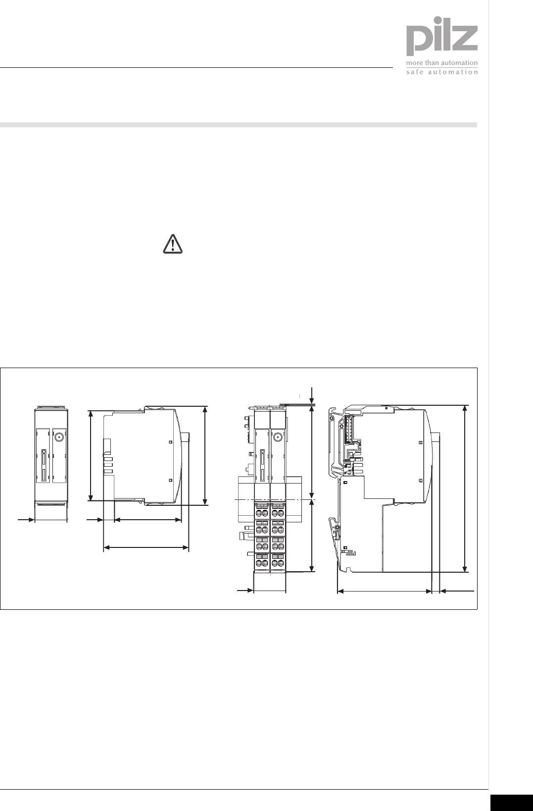
5.1.1 Dimensions
Dimensions5-
A min. 15 cm clearance is required above the mounting rail in the control
cabinet to connect the antenna cable on the module.
CAUTION!
Damage due to electrostatic discharge!
Electrostatic discharge can damage components. Ensure
against discharge before touching the product, e.g. by touching
an earthed, conductive surface or by wearing an earthed arm-
band.
25,2 mm
76 mm
52,1 mm
67,7 mm
25,2 mm
56,1 mm 71,8 mm 0,8 mm
128,9 mm
72,7 mm
(2.862")
(2.992")
(2.209") (2.827") (0.031")
5.075")
(0.992") (2.051")
8,1 mm
(0.319")
(0.992")
(2.665")
65,6 mm
(2.582")
5,4 mm
(0.213")
5.1 General installation guidelines
5 Installation
Pilz GmbH & Co. KG, Sichere Automation, Felix-Wankel-Straße 2, 73760 Ostfildern, Germany
Telephone: +49 711 3409-0, Telefax: +49 711 3409-133, E-Mail: pilz.gmbh@pilz.de
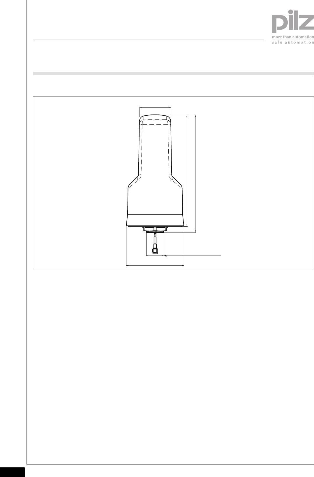
5-2
Dimensions of the antenna ANT1/ANT2 (ANT 2 for base station only):
42,3/56,2 mm
70,0/103,7 mm
M32x1,5 mm
136,5/201,5 mm
147,3/212,3 mm

Pilz GmbH & Co. KG, Sichere Automation, Felix-Wankel-Straße 2, 73760 Ostfildern, Germany
Telephone: +49 711 3409-0, Telefax: +49 711 3409-133, E-Mail: pilz.gmbh@pilz.de 5-3
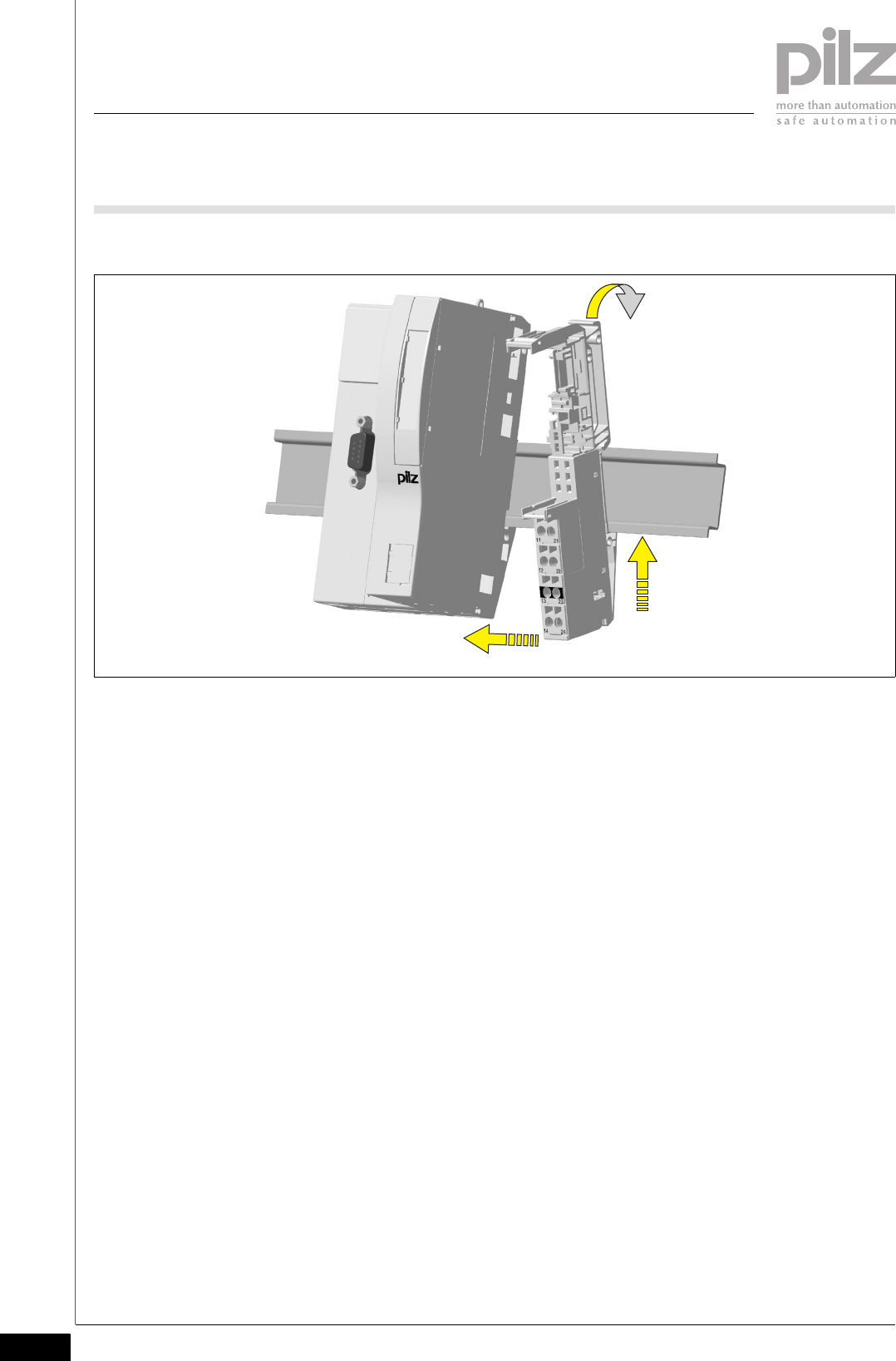
5.2 Install base station
5 Installation
5.2Install base station5200Install base station5-
The base station always provides the termination for a PSSuniversal
system. No further modules may be positioned to the right of the base
station.
Prerequisite:
`The head module must be installed.
`A base module for a supply voltage module is always connected to the
right of the head module.
Please note:
`For mechanical reasons it is not possible to mix base modules with
screw terminals and base modules with cage clamp terminals.
`All contacts should be protected from contamination.
`The mechanics of the base modules are designed for 50 plug in/out
cycles.
Procedure:
`We recommend that you wire up the base modules before inserting
the electronic modules.
`Slot the groove on the base module on to the mounting rail from below
[1].
`Push the base module back [2] until you hear it lock into position.
`On the mounting rail, slide the base module to the left until you hear
the two lateral mounting hooks on the adjacent module lock into posi-
tion [3].
5.2 Install base station
5 Installation
Pilz GmbH & Co. KG, Sichere Automation, Felix-Wankel-Straße 2, 73760 Ostfildern, Germany
Telephone: +49 711 3409-0, Telefax: +49 711 3409-133, E-Mail: pilz.gmbh@pilz.de
5-4
Schematic representation:
[2]
[1]
[3]
Pilz GmbH & Co. KG, Sichere Automation, Felix-Wankel-Straße 2, 73760 Ostfildern, Germany
Telephone: +49 711 3409-0, Telefax: +49 711 3409-133, E-Mail: pilz.gmbh@pilz.de 5-5
5.3 Inserting and removing an electronic module
5 Installation
5.3Inserting and removing an electronic module5300Inserting and removing an electronic module5-
Please note:
`Only insert on to base modules that are already installed.
`Preferably these base modules should be ready wired.
`Electronic modules with outputs may only be inserted and removed
when the load is switched off. Unforeseeable error reactions may be
triggered if modules are inserted and removed under load.
`When an electronic module is plugged into a base module for the first
time, one part of the coding element remains on the electronic module,
while its counterpart is fixed on to the base module. This is how the
base module is coded.
`The mechanics of the electronic modules are designed for 50 plug in/
out cycles.
5.3.1 Inserting an electronic module
Inserting an electronic module5-
Procedure:
`The electronic module must audibly lock into position [1].
`Mark the electronic module using the labelling strips [2].
Schematic representation:
[2]
[1]
[1]
5.3 Inserting and removing an electronic module
5 Installation
Pilz GmbH & Co. KG, Sichere Automation, Felix-Wankel-Straße 2, 73760 Ostfildern, Germany
Telephone: +49 711 3409-0, Telefax: +49 711 3409-133, E-Mail: pilz.gmbh@pilz.de
5-6
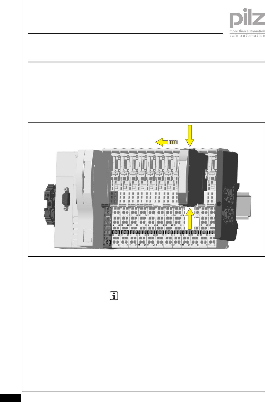
5.3.2 Removing an electronic module
Removing an electronic module5-
Procedure:
`Press the locking mechanisms [1] together simultaneously.
`Pull out the electronic module [2].
Schematic representation:
5.3.3 Changing an electronic module during operation
Changing an electronic module during operation5-
INFORMATION
After a module has been changed during operation, in some cir-
cumstances the remote stations may no longer be detected cor-
rectly.
Only change the module in the off state!
[1]
[2]
[1]
Pilz GmbH & Co. KG, Sichere Automation, Felix-Wankel-Straße 2, 73760 Ostfildern, Germany
Telephone: +49 711 3409-0, Telefax: +49 711 3409-133, E-Mail: pilz.gmbh@pilz.de 5-7
5.4 Antenna assembly
5 Installation
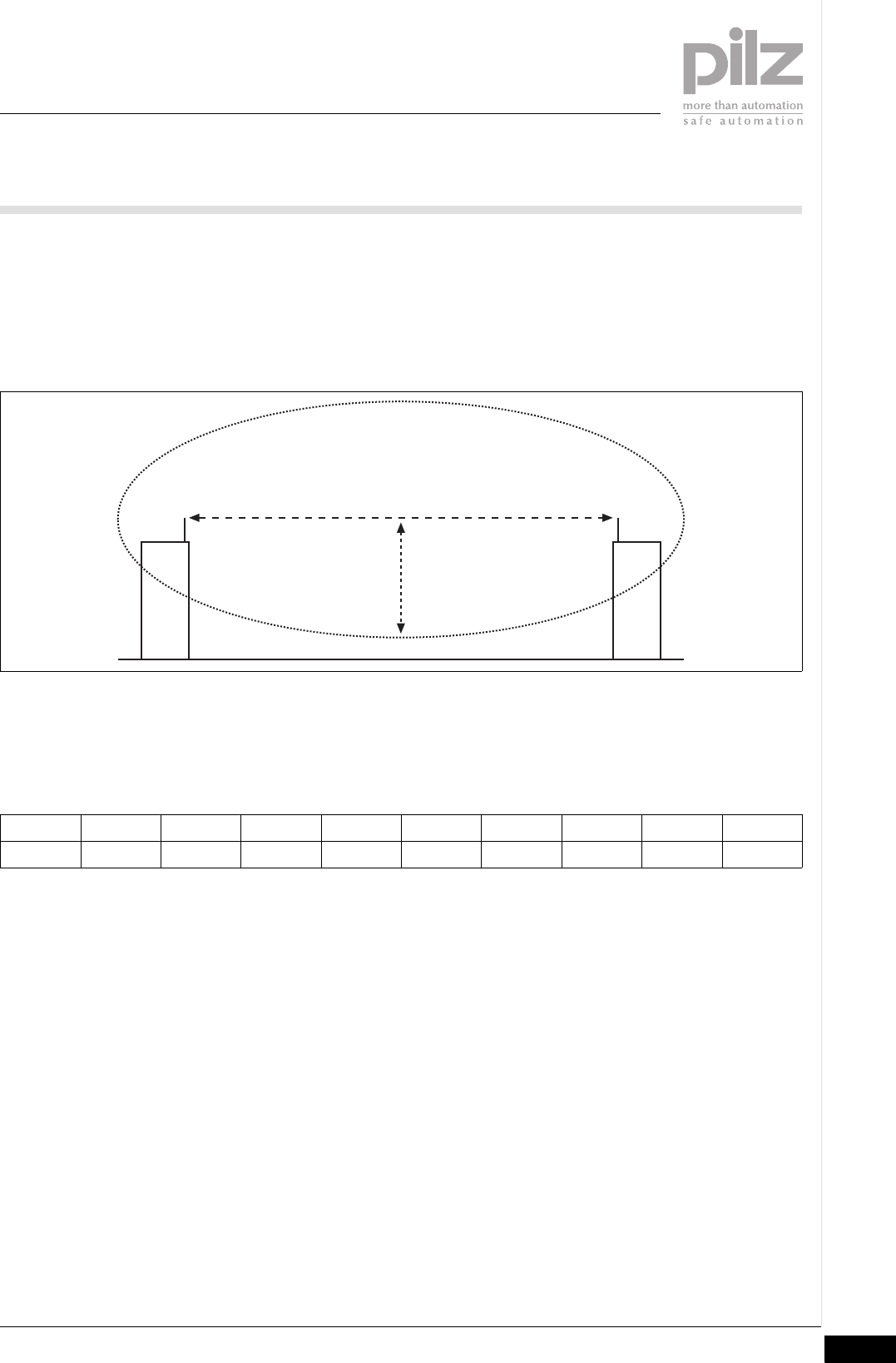
5.4Antenna assembly5400Antenna assembly5-
As with all radio signals, the InduraNET p signals will mainly propagate
in the first Fresnel zone. The Fresnel zone is a spheroid, in whose focus
the antennas are located.
Schematic representation:
The size of the Fresnel zone depends on the wavelength of the radio sig-
nal and the distance of the antennas.
At 2.4 GHz, approximate values for the Fresnel zone's radius R in rela-
tion to antenna distance d:
d [m]5 8 121620305075100
R [m] 0,4 0,5 0,6 0,7 0,8 0,9 1,3 1,5 1,8
d
R
5.4 Antenna assembly
5 Installation
Pilz GmbH & Co. KG, Sichere Automation, Felix-Wankel-Straße 2, 73760 Ostfildern, Germany
Telephone: +49 711 3409-0, Telefax: +49 711 3409-133, E-Mail: pilz.gmbh@pilz.de
5-8
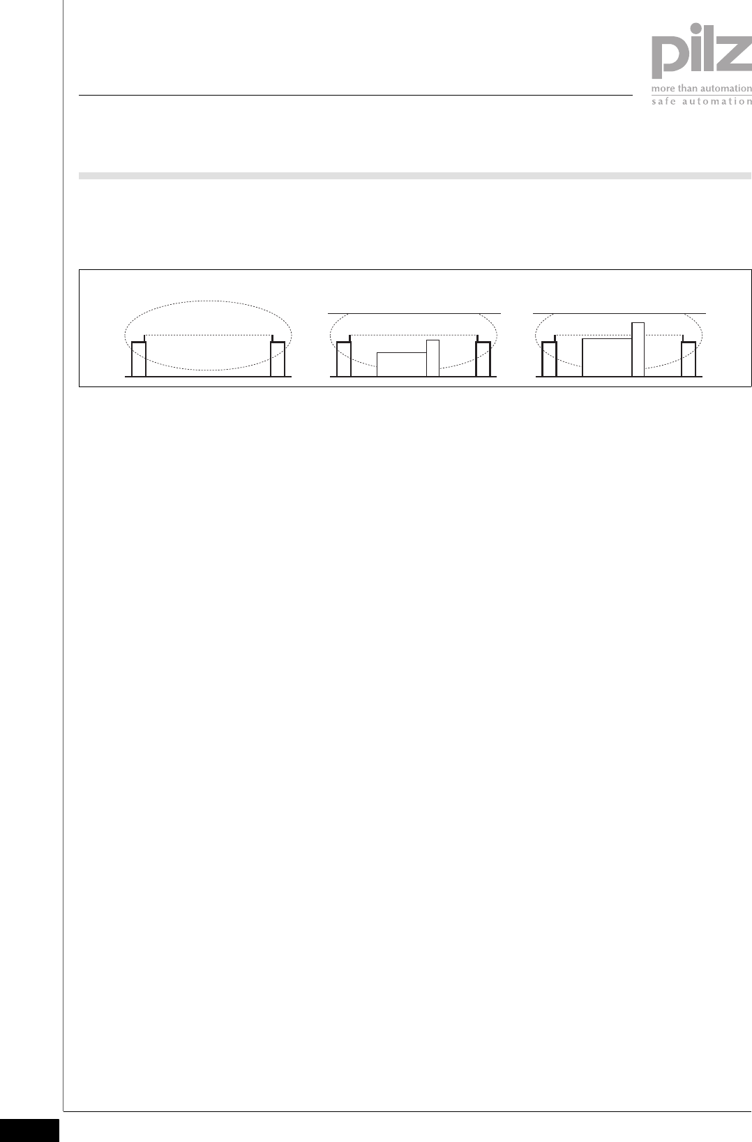
Reception will deteriorate if any objects or parts of the building lie within
the Fresnel zone. When positioning the antennas it is possible to distin-
guish between three scenarios:
`A: The Fresnel zone is not adversely affected.
– Optimum conditions
`B: The Fresnel zone is adversely affected by the low ceiling and by an
object between the antennas. There is visual contact between the an-
tennas (straight, dotted line).
– These Fresnel zone encroachments will reduce the reception quality.
The signals' operating range will be shorter.
`C: There is no visual contact between the antennas.
– Unfavourable conditions. The signals are only transmitted indirectly
and via reflections.
Please note also:
`The antenna are designed for use inside buildings, particularly on fac-
tory floors.
`The optimum installation height of the antennas is 1.80 m – 2.00 m,
e.g. on top of a control cabinet.
`The optimum orientation of the installed antenna is vertical on a hori-
zontal surface.
`People standing within the Fresnel zone have a particularly adverse ef-
fect on reception quality.
`Reflections from walls (concrete, metal) lead to local signal quenching.
– A diverse antenna (PSS ANT 2 IDN, available as an accessory) can
help to improve reception quality on mobile, remote stations.
A B C

Pilz GmbH & Co. KG, Sichere Automation, Felix-Wankel-Straße 2, 73760 Ostfildern, Germany
Telephone: +49 711 3409-0, Telefax: +49 711 3409-133, E-Mail: pilz.gmbh@pilz.de 5-9
5.5 Install antenna
5 Installation
5.5Install antenna 5500Install antenna 5-
The antenna is positioned on the control cabinet or on a flat surface, us-
ing one hole mounting. The InduraNET p antenna cable is a 2 m long co-
axial cable for high frequency applications with an impedance level of
50 Ohms.
Please refer to the section entitled "Antenna assembly" for information
on providing sufficient reception.
Procedure:
`In the control cabinet ceiling, punch or drill a hole suitable to take an
M32 thread fitting (> 32 mm diameter).
`Feed the antenna cable through the punched hole and assemble the
antenna.
`Screw on the antenna using the nut on the M32 thread.
`Install the antenna cable from the antenna to the InduraNET p station.
– The minimum bending radius is 15 mm.
– The antenna cable must not be bent or trapped.
– The antenna cable must not be split and then rejoined.
– Excess cable must not be wound like a coil. Excess cable should be
looped.
`Screw the antenna cable on to the socket labelled “ANT” on the
InduraNET p station.
– The torque on the SMA screw connection is 0.7 – 1.1 Nm. You can
achieve the appropriate torque by tightening the screw firmly by
hand.
NOTICE
InduraNET p devices may be damaged if they are operated with-
out an antenna.
`Always operate the PSSu WB S IDN device with the antenna
connected.
CAUTION!
The radio approval will be rendered invalid if a third-party
antenna is used.
`InduraNET p devices should only be used with the antennas
PSS ANT 1 IDN and PSS ANT 2 IDN.

5.5 Install antenna
5 Installation
Pilz GmbH & Co. KG, Sichere Automation, Felix-Wankel-Straße 2, 73760 Ostfildern, Germany
Telephone: +49 711 3409-0, Telefax: +49 711 3409-133, E-Mail: pilz.gmbh@pilz.de
5-10
The 2 m extension cable attenuates the signal by approx. 3 dB. Attenu-
ation of 3 dB halves the transmitted output. For this reason, only use the
extension cable where reception conditions are good and operating
ranges are short.
`For reasons of electromagnetic compatibility, the extension cable may
only be laid with group 1 cables (see PSSuniversal Installation Manual)
Pilz GmbH & Co. KG, Sichere Automation, Felix-Wankel-Straße 2, 73760 Ostfildern, Germany
Telephone: +49 711 3409-0, Telefax: +49 711 3409-133, E-Mail: pilz.gmbh@pilz.de 6-1
6.1 General wiring guidelines
6 Wiring
66000WiringWiring6-6.1General wiring guidelines6100General wiring guidelines6-
Please note:
`The maximum current load for the periphery supply on the module bus
is 10 A.
`The external power supplies must comply with the current applicable
standard EN 60950-1, EN 61140, EN 50178 or EN 61558-1.
`Use copper wiring.
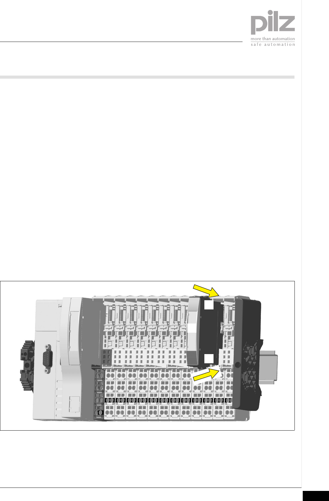
6.1.1 Mechanical connection of the base modules
Mechanical connection of the base modules6-
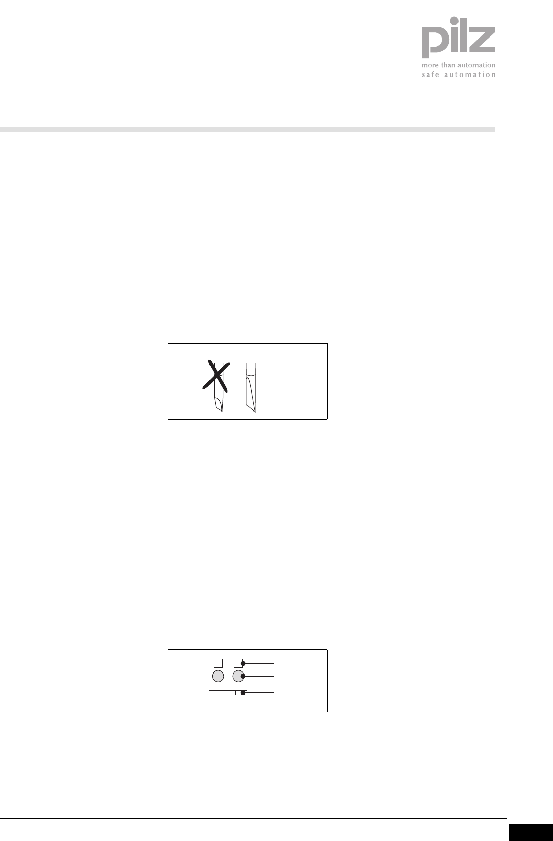
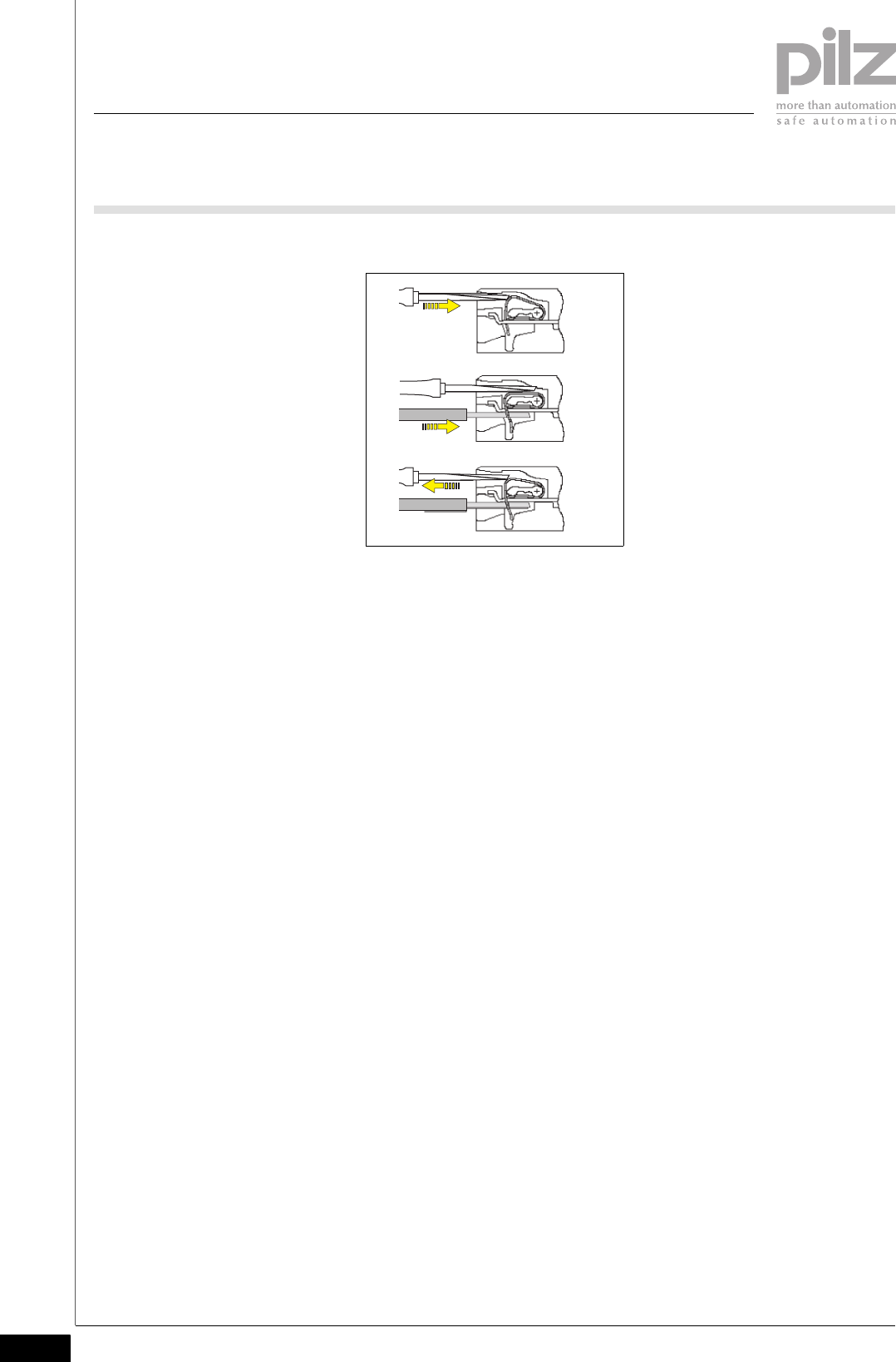
Procedure:
`Use a flat blade screwdriver (DIN 5264-A)!
`Strip the wire back 8 mm.
`If necessary, label the connection level with a colour marker [3].
`Base module with screw terminals:
– Use a screwdriver to loosen the screw on the screw terminal [1]
– Insert the stripped cable into the round fixing hole [2], as far as it will
go.
– Tighten up the screw on the screw terminal.
– Check that the cable is firmly seated.
`Base module with cage clamp terminals:
– Insert the screwdriver [4] into the square hole [1].
– Insert the stripped cable into the round fixing hole [2], as far as it will
go [5].
– Pull out the screwdriver [6].
– Check that the cable is firmly seated.
DIN 5264-A
2111
[1]
[3]
[2]
6.1 General wiring guidelines
6 Wiring
Pilz GmbH & Co. KG, Sichere Automation, Felix-Wankel-Straße 2, 73760 Ostfildern, Germany
Telephone: +49 711 3409-0, Telefax: +49 711 3409-133, E-Mail: pilz.gmbh@pilz.de
6-2
Please note:
`The minimum cable cross section for field connection terminals on the
base modules is 0.14 mm2 (AWG26)
`The maximum cable cross section for field connection terminals is:
– Digital inputs: 1.5 mm2 (AWG16)
– Digital outputs: 2.0 mm2 (AWG14)
– Inputs/outputs on the counter modules: 1.5 mm2 (AWG16)
– Analogue inputs/outputs: 1.5 mm2 (AWG16)
– Communication cables: 1.5 mm2 (AWG16)
– Test pulse outputs: 1.5 mm2 (AWG16)
– Power supply: 2.5 mm2 (AWG12)
– Functional earth: 2.5 mm2 (AWG12)
`On base modules with screw terminals:
– If you use a multi-strand cable to connect the I/Os, it is recommend-
ed that you use ferrules conforming to Parts 1 and 2 of DIN 46228,
0.14 ... 1.5 mm2, Form A or C, although this is not essential. To crimp
the ferrules you can use crimp pliers (crimp form A or C) conforming
to EN 60947-1, such as the PZ 1.5 or PZ 6.5 from Weidmüller, for
example.
`Use copper wiring.
[4]
[5]
[6]
Pilz GmbH & Co. KG, Sichere Automation, Felix-Wankel-Straße 2, 73760 Ostfildern, Germany
Telephone: +49 711 3409-0, Telefax: +49 711 3409-133, E-Mail: pilz.gmbh@pilz.de 6-3
6.2 Terminal configuration
6 Wiring
6.2Terminal configuration6200Terminal configuration6-
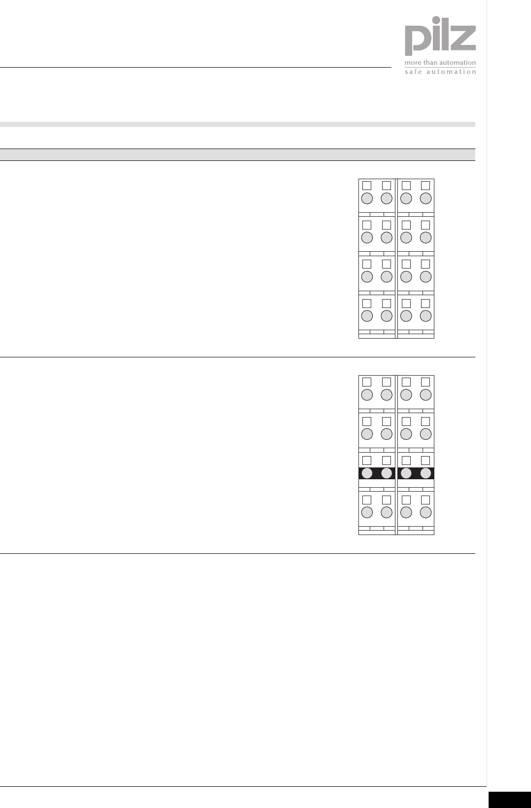
Base module Terminal configuration
Screw terminals:
PSSu BP 2/16S
Cage clamp terminals:
PSSu BP 2/16C
Without C-rail:
11- 21: Potential P1
(11-21 linked internally)
12-22: Potential P2
(12-22 linked within the base module)
13-23: Potential P3
(13-23 linked within the base module)
14-24: Potential P4
(14-24 linked internally)
31-44: Not connected
32-42: Not connected
33-43: Not connected
34-44: Not connected
Screw terminals:
PSSu BP-C 2/16S
Cage clamp terminals:
PSSu BP-C 2/16C
With C-rail:
11- 21: Potential P1
(11-21 linked internally)
12-22: Potential P2
(12-22 linked within the base module)
13-23-33-43: C-rail supply
(13-23-33-43 linked within the base
module)
14-24: Potential P4
(14-24 linked internally)
31-44: Not connected
32-42: Not connected
34-44: Not connected
2111
2212
2313
2414
4131
4232
4333
4434
2111
2212
2313
2414
4131
4232
4333
4434

6 Wiring
Pilz GmbH & Co. KG, Sichere Automation, Felix-Wankel-Straße 2, 73760 Ostfildern, Germany
Telephone: +49 711 3409-0, Telefax: +49 711 3409-133, E-Mail: pilz.gmbh@pilz.de
6-4
Pilz GmbH & Co. KG, Sichere Automation, Felix-Wankel-Straße 2, 73760 Ostfildern, Germany
Telephone: +49 711 3409-0, Telefax: +49 711 3409-133, E-Mail: pilz.gmbh@pilz.de 7-1
7.1 Messages
7 Operation
77000OperationOperation7-7.1Messages7100Messages7-
A module error is displayed via the “Err” LED (see section entitled “Dis-
play elements”), signalled to the head module and then entered in the
head module's error stack.
The module can detect the following errors:
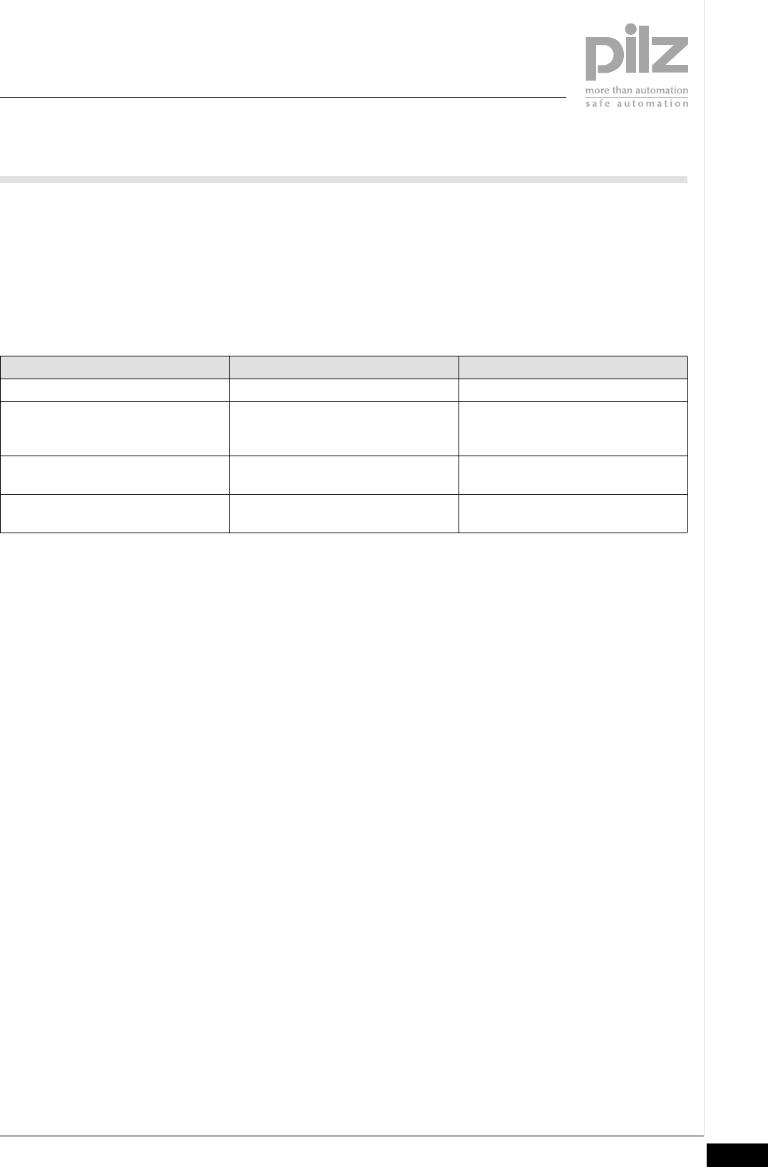
Module error Explanation Remedy
Start-up error Error as the PSSu system starts up. Change faulty module.
Configuration Error Incorrect module type configured. The configured hardware registry does
not match the actual hardware regis-
try.
ST communication error Error in ST communication with the
head module.
Change faulty module.
Bus termination error There is no end bracket. Install a terminating plate with inte-
grated end angle.
7.2 Display elements
7 Operation
Pilz GmbH & Co. KG, Sichere Automation, Felix-Wankel-Straße 2, 73760 Ostfildern, Germany
Telephone: +49 711 3409-0, Telefax: +49 711 3409-133, E-Mail: pilz.gmbh@pilz.de
7-2
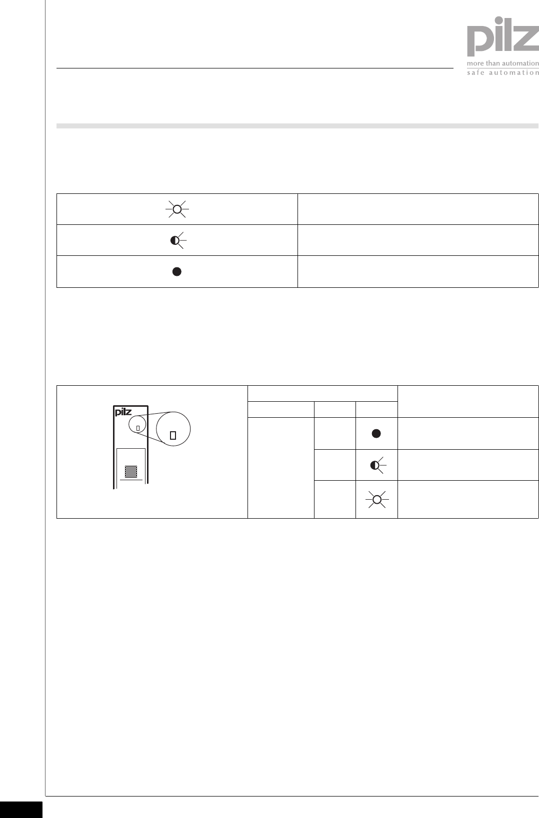
7.2Display elements7200Display elements7-
Key:
7.2.1 Display elements for InduraNET p diagnostics
Display elements for InduraNET p diagnostics7-
The module has an LED for displaying errors (“Err” LED).
LED on
LED flashes
LED off
LED Key
Name Colour Status
Err - - - No error
Red Chip card error
Red Error when comparing the actual/
registered hardware on the re-
mote systems
Err
11
I0 21
I1
Err
Pilz GmbH & Co. KG, Sichere Automation, Felix-Wankel-Straße 2, 73760 Ostfildern, Germany
Telephone: +49 711 3409-0, Telefax: +49 711 3409-133, E-Mail: pilz.gmbh@pilz.de 7-3
7.2 Display elements
7 Operation
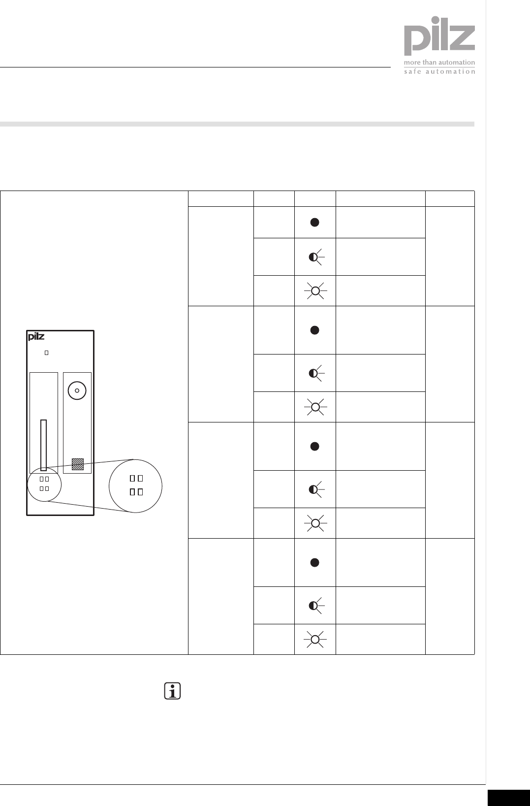
Each remote station is assigned an LED to display the connection status
(LEDs “R1”, “R2”, “R3” and “R4”).
Name Colour Status Signal Target
R1 - - - No data transfer Remote
station 1
Green Establishing a con-
nection or connec-
tion disrupted.
Green Data is being trans-
mitted
R2 - - - No data is being
transmitted/no re-
mote system is con-
figured
Remote
station 2
Green Establishing a con-
nection or connec-
tion disrupted.
Green Data is being trans-
mitted
R3 - - - No data is being
transmitted/no re-
mote system is con-
figured
Remote
station 3
Green Establishing a con-
nection or connec-
tion disrupted.
Green Data is being trans-
mitted
R4 - - - No data is being
transmitted/no re-
mote system is con-
figured
Remote
station 4
Green Establishing a con-
nection or connec-
tion disrupted.
Green Data is being trans-
mitted
INFORMATION
After a restart the InduraNET p configuration data is loaded from
the chip card. This process lasts approximately 5 s. During this
time the LEDs will flash in quick succession.
Err
000000
000
R1
R2
R3
R4
CHIP ANT
R1
R2 R3
R4

7 Operation
Pilz GmbH & Co. KG, Sichere Automation, Felix-Wankel-Straße 2, 73760 Ostfildern, Germany
Telephone: +49 711 3409-0, Telefax: +49 711 3409-133, E-Mail: pilz.gmbh@pilz.de
7-4
Pilz GmbH & Co. KG, Sichere Automation, Felix-Wankel-Straße 2, 73760 Ostfildern, Germany
Telephone: +49 711 3409-0, Telefax: +49 711 3409-133, E-Mail: pilz.gmbh@pilz.de 8-1
8.1 Technical details
8 Technical details
88000Technical detailsTechnical details8-8.1Technical details8100Technical details8-
Technical details PSSu WB S IDN
Application range Standard
Module's device code 0005h
Electrical data
Internal supply voltage
Supply voltage range of module supply 4.8 - 5.4 V
Current and power consumption from module supply
Module's current consumption 107 mA
Module's power consumption 0.55 W
InduraNET p interface
Scope Standard applications
Application in accordance with ARIB STO-T 66 (19,2), EN 300328 V1,7,1, EN 301489-1
V1,6,1, EN 301489-3 V1,4,1, FCC Part 15-249, IEC 60950
Working frequency range 2,405 - 2,479 MHz
Channel spacing 1 MHz
Number of channels 75
Modulation GFSK
Frequency deviation -160 - 160 kHz
Typ. transmitter output EIRP 18 dBm/64 mW
Max. transmitter output EIRP 20 dBm/100 mW
Receiver type Superhet
Max. receiver sensitivity when PER=0.1% -90 dBm
Frequency stability -2.5 - 2.5 ppm
Intermediate frequency fZF=fLO-fRX=(8/7*fRX+2MHz)-fRX
Environmental data
Climatic suitability EN 60068-2-14, EN 60068-2-1, EN 60068-2-2, EN 60068-
2-30, EN 60068-2-78
Ambient temperature 0 - 60 °C
Storage temperature -25 - 70 °C
Climatic suitability in accordance with EN 60068-2-30,
EN 60068-2-78
93 % r. h. at 40 °C
Condensation no
EMC EN 55011: class A, EN 61000-4-2, EN 61000-4-3,
EN 61000-4-4, EN 61000-4-5, EN 61000-4-6, EN 61131-2
Vibration to EN 60068-2-6
Frequency 10 - 60 Hz
Max. acceleration 1g
Shock stress
EN 60068-2-27 15g
11 ms
Protection type
Mounting (e.g. cabinet) IP54
Housing IP20
Terminals IP20
Airgap creepage in accordance with EN 60664-1
Overvoltage II
Pollution degree 2
Mechanical data
Housing material
Front PC
Bottom PC

8.1 Technical details
8 Technical details
Pilz GmbH & Co. KG, Sichere Automation, Felix-Wankel-Straße 2, 73760 Ostfildern, Germany
Telephone: +49 711 3409-0, Telefax: +49 711 3409-133, E-Mail: pilz.gmbh@pilz.de
8-2
Dimensions
Height 76.0 mm
Width 25.4 mm
Depth 60.2 mm
Colour of front plate dark grey
Weight 57 g
Mechanical data

• …• www
21 835-01, 2008-03 Printed in Germany
© Pilz GmbH & Co. KG, 2008
Pilz GmbH & Co. KG
Sichere Automation
Felix-Wankel-Straße 2
73760 Ostfi ldern, Germany
Telephone: +49 711 3409-0
Telefax: +49 711 3409-133
E-Mail: pilz.gmbh@pilz.de
www.pilz.com
+49 711 3409-444
• Technical support
In many countries we are
represented by sales partners.
Please refer to our homepage
for further details or contact our
headquarters.