Pilz and KG PSENCS3 RFID Proximity switch User Manual
Pilz GmbH & Co. KG RFID Proximity switch
Contents
- 1. manual part_1
- 2. manual part_2
manual part_1
22172-3FR-01
PSEN cs3.1n
- 1 -
4D Betriebsanleitung
4GB Operating instructions
4F Manuel d'utilisation
22172-3FR-01PSEN cs3.1n
Sicherheitsschalter PSEN cs3.1n
1185799819
Der Sicherheitsschalter erfüllt die Anforderun-
gen nach:
`EN 60204-1
`EN 60947-5-3: PDF-M zusammen mit dem
Betätiger (siehe Technische Daten).
`EN 62061: SIL CL 3
`EN ISO 13849-1. PL e und Kat. 4
`Der Sicherheitsschalter darf nur mit dem zu-
gehörigen Betätiger verwendet werden (sie-
he Technische Daten).
`Die Sicherheitsausgänge müssen 2-kanalig
weiterverarbeitet werden.
Safety switch PSEN cs3.1n
The safety switch meets the requirements in
accordance with:
`EN 60204-1
`EN 60947-5-3: PDF-M in conjunction with
the actuator (see Technical Details).
`EN 62061: SIL CL 3
`EN ISO 13849-1. PL e and Cat. 4
`The safety switch may only be used with the
corresponding actuator (see Technical De-
tails).
`The safety outputs must use 2-channel
processing.
Capteur de sécurité PSEN cs3.1n
Le capteur de sécurité satisfait aux exigences
des normes :
`EN 60204-1
`EN 60947-5-3 : PDF-M avec l'actionneur
(voir les caractéristiques techniques).
`EN 62061 : SIL CL 3
`EN ISO 13849-1. PL e et cat. 4
`Le capteur de sécurité doit être utilisé uni-
quement avec l'actionneur correspondant
(voir les caractéristiques techniques).
`Les sorties de sécurité doivent être traitées
par 2 canaux.
Zu Ihrer Sicherheit
547263243
`Installieren und nehmen Sie das Gerät nur
dann in Betrieb, wenn Sie diese Betriebsan-
leitung gelesen und verstanden haben und
Sie mit den geltenden Vorschriften über Ar-
beitssicherheit und Unfallverhütung vertraut
sind.
Beachten Sie die VDE- sowie die örtlichen
Vorschriften, insbesondere hinsichtlich
Schutzmaßnahmen
`Durch Öffnen des Gehäuses oder eigen-
mächtige Umbauten erlischt jegliche Ge-
währleistung.
777809547
`Entfernen Sie die Schutzkappe erst unmittel-
bar vor Anschluss des Geräts.
For your safety
`Only install and commission the unit if you
have read and understood these operating
instructions and are familiar with the applica-
ble regulations for health and safety at work
and accident prevention.
Ensure VDE and local regulations are met,
especially those relating to safety.
`Any guarantee is rendered invalid if the hous-
ing is opened or unauthorised modifications
are carried out.
`Do not remove the protective cap until you
are just about to connect the unit.
Pour votre sécurité
`Vous n'installerez l'appareil et ne le mettrez
en service qu'après avoir lu et compris le
présent manuel d'utilisation et vous être fa-
miliarisé avec les prescriptions en vigueur
sur la sécurité du travail et la prévention des
accidents.
Respectez les normes locales ou VDE, parti-
culièrement en ce qui concerne la sécurité.
`L'ouverture de l'appareil ou sa modification
annule automatiquement la garantie.
`Veuillez retirer le cache de protection avant
de raccorder l'appareil.
Gerätemerkmale
1176593035
`Transpondertechnik
`Zweikanaliger Betrieb
`2 Sicherheitsausgänge
`LED-Anzeige für:
– Zustand Betätiger
– Versorgungsspannung/Fehler
`1 Betätigungsrichtung
`5-poliger M12 Stiftstecker
`Codierung: codiert
Unit features
`Transponder technology
`Dual-channel operation
`2 safety outputs
`LED for:
– Status of the actuator
– Supply voltage/fault
`1 direction of actuation
`5 pin M12 male connector
`Coding: coded
Caractéristiques de l'appareil
`Technique à transpondeur
`Commande par 2 canaux
`2 sorties de sécurité
`LEDs de visualisation :
– état de l'actionneur
– tension d'alimentation / défauts
`1 sens de manœuvre
`Connecteur mâle à 5 broches M12
`Code : codé
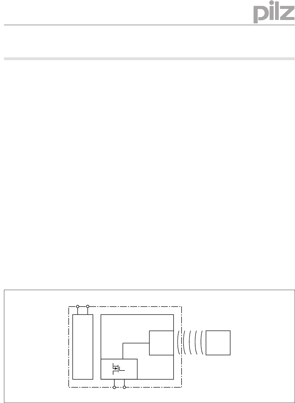
Blockschaltbild Block diagram Schéma de principe
A1 A2
Power
12 22
Receiver Actuator
- 2 -
Funktionsbeschreibung
1176789259
Die Sicherheitsausgänge 12 und 22 leiten,
wenn
`der Betätiger sich im Ansprechbereich befin-
det
Die Sicherheitsausgänge 12 und 22 sperren,
wenn
`der Betätiger sich außerhalb des Ansprech-
bereichs befindet
Function description
Safety outputs 12 and 22 conduct when
`the actuator is in the response range
Safety outputs 12 and 22 are disabled when
`the actuator is outside the response range
Description du fonctionnement
Les sorties de sécurité 12 et 22 sont sous ten-
sion si
`l'actionneur se trouve dans la zone de détec-
tion
Les sorties de sécurité 12 et 22 sont ver-
rouillées si :
`l'actionneur se trouve à l'extérieur de la zone
de détection ou si
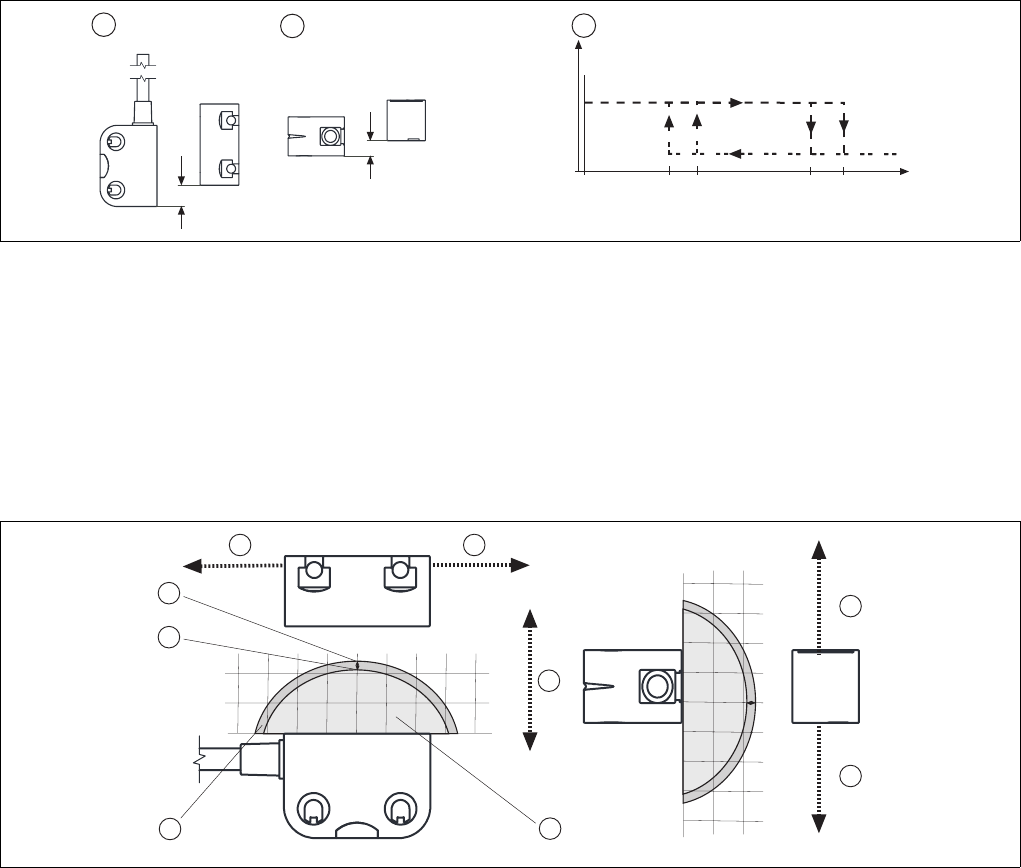
Schaltabstände Operating distances Distances de commutation
Legende
1091682571
`c: Seitenversatz
`d: Höhenversatz
`e: Schaltzustände (y-Achse) in Abhängigkeit
der Schaltabstände (x-Achse)
`Sao: Gesicherter Schaltabstand: 8,0 mm
`So: Typischer Schaltabstand: 11,0 mm
`Sr: Typischer Ausschaltabstand: 14,0 mm
`Sar: Gesicherter Ausschaltabstand: 20 mm
Key
`c: Lateral offset
`d: Vertical offset
`e: Switch statuses (y-axis) dependent on
operating distances (x-axis)
`Sao: Assured operating distance: 8,0 mm
`So: Typical operating distance: 11,0 mm
`Sr: Typical release distance: 14,0 mm
`Sar: Assured release distance: 20 mm
Légende
`c: décalage latéral
`d: décalage en hauteur
`e: états de commutation (axe y) en fonction
des distances de commutation (axe x)
`Sao : distance de commutation de sécurité :
8,0 mm
`So : distance de commutation caractéristi-
que : 11,0 mm
`Sr : distance de déclenchement caractéristi-
que : 14,0 mm
`Sar : distance de déclenchement de sécurité
: 20 mm
Seiten- und Höhenversatz Lateral and vertical offset Décalage latéral et en hauteur
Legende
1176622859
`c: Hysterese
`d: Typischer Schaltabstand SO
`e: Typischer Ausschaltabstand Sr
`f: Versatz in mm
`g: Schaltabstand in mm
`h: Ansprechbereich
Key
`c: Hysteresis
`d: Typical operating distance SO
`e: Typical release distance Sr
`f: Offset in mm
`g: Operating distance in mm
`h: Response range
Légende
`c: Hystérésis
`d: Distance approximative de commutation
SO
`e: Distance approximative de déclenche-
ment Sr
`f: Décalage en mm
`g: Distance de commutation en mm
`h: Zone de déclenchement
Ein/On/Marche
Aus/Off/Arrêt
(mm)s
omin
s
ao
s
ar
123
s
o
s
r
y
x
1
2
3
4 4
5
6
0
5
10
046810-4-6-8-10
0
5
10
mm
0
4
6
8
10
-4
-6
-8
-10
0510
mm
0510
4
4
- 3 -
Verdrahtung
517049611
Beachten Sie:
`Angaben im Abschnitt „Technische Daten“
unbedingt einhalten.
`Berechnung der max. Leitungslänge Imax im
Eingangskreis:
Rlmax = max. Gesamtleitungswiderstand
(s. techn. Daten)
Rl/ km = Leitungswiderstand/km
Wiring
Please note:
`Information given in the “Technical details”
must be followed.
`Calculation of the max. cable length lmax in
the input circuit:
Rlmax = max. overall cable resistance (see
Technical details)
Rl / km = cable resistance/km
Raccordement
Important :
`Respectez impérativement les données indi-
quées dans la partie "Caractéristiques tech-
niques".
`Calcul de la longueur de câble max. Imax sur
le circuit d'entrée :
Rlmax = résistance max. de l'ensemble du
câblage (voir les caractéristiques techni-
ques)
Rl / km = résistance du câblage/km
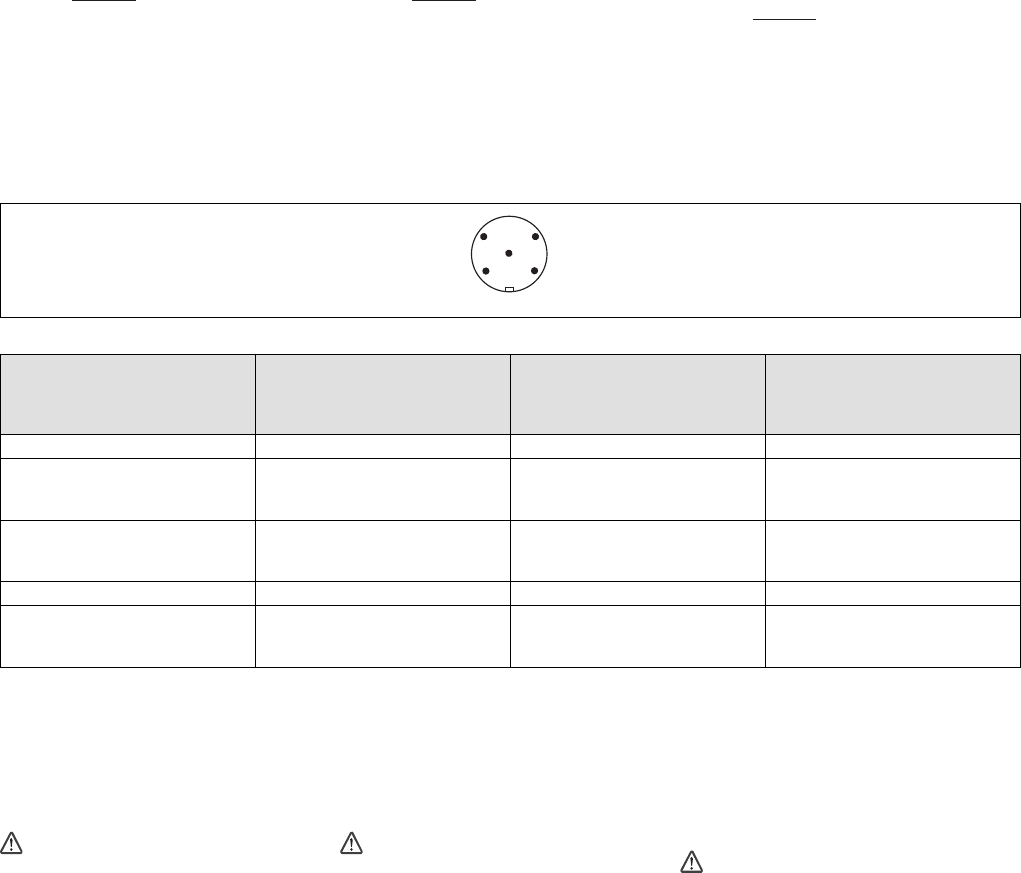
Anschlüsse Connections Raccordements
Stiftstecker 5-pol. M12 (male) Connector 5 pin M12 (male) Connecteur mâle M12 à 5 broches
Anschlussbelegung Stecker und Kabel Pin assignment, connector and cable Affectation des bornes - connecteur et câble
Anschlussbezeichnung im
Blockschaltbild/
Terminal designation/
Désignation des bornes
Funktion/
Function/
Foncion
PIN/
Broche Adernfarbe (Pilz Kabel)/
Cable colour (Cable Pilz)/
Couleur du fil (fil de Pilz)
A1 +24 UB 1 braun/brown/marron
12 Ausgang Kanal 1/
Output, channel 1/
Canal de sortie 1
2 weiß/white/blanc
22 Ausgang Kanal 2/
Output, channel 2/
Canal de sortie 2
4 schwarz/black/noir
A2 0 V UB 3 blau/blue/bleu
- nicht anschließen/
do not connect/
pas raccordé
5 grau/grey/gris
Anschluss an Auswertegeräte
1104750091
Bitte beachten Sie:
`das Netzteil muss den Vorschriften für Klein-
spannungen mit sicherer Trennung (SELV,
PELV) entsprechen.
`die Ein- und Ausgänge des Sicherheitsschal-
ters müssen eine sichere Trennung zu Span-
nungen über 60 V AC besitzen.
1090417163
ACHTUNG!
Die Sicherheitsausgänge müssen 2-ka-
nalig weiterverarbeitet werden.
Connection to evaluation devices
Please note:
`The power supply must meet the regulations
for extra low voltages with safe separation
(SELV, PELV).
`the inputs and outputs of the safety switch
must have a safe separation to voltages over
60 V AC.
CAUTION!
The safety outputs must use 2-channel
processing.
Raccordement aux appareils de contrôle
Tenez compte de ce qui suit :
`Cette alimentation doit être conforme aux
prescriptions relatives aux basses tensions à
séparation galvanique (SELV, PELV).
`Les entrées et les sorties du capteur de sé-
curité doivent posséder une séparation gal-
vanique pour les tensions supérieures à
60 V AC.
ATTENTION !
Les sorties de sécurité doivent être trai-
tées par 2 canaux.
Rlmax
Rl / km
Imax = Rlmax
Rl / km
Imax = Rlmax
Rl / km
Imax =
12
3
5
4
- 4 -
`Anschaltung `Interface `Raccordement
`Anschluss an PDP67 `Connection to PDP67 `Raccordement à PDP67
12 22
24 V 0 V
I1 (FS)
A1
A2
A1
A2
Empfänger/
Reciever/
Recépteur
Betätiger/
Actuator/
Actioneur
Auswertegerät/
Evaluation device/
Appareil de surveillance
FS: Fail-safe
ST: Standard
I2 (FS)
PDP67 F 8DI ION
Test Pulse X / 24 V DC
0 V
1
3
Input X
Input X + 1
2
4
5
A1
A2
12
22
n.c.
PDP67 PSENcode
1
3
Test Pulse X + 1 / 24 V DC
2
4
5
- 5 -
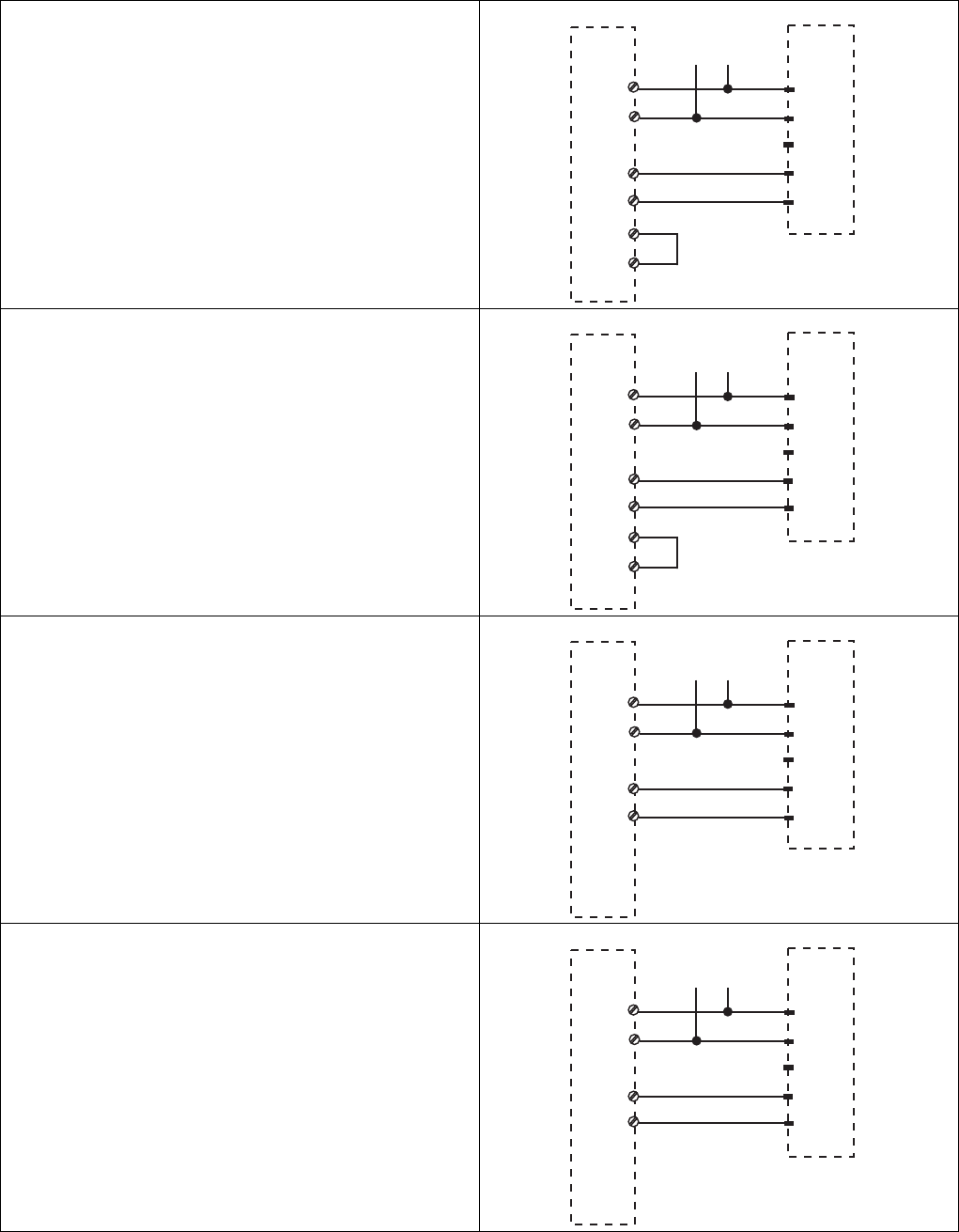
`Anschluss an PNOZ X, PNOZpower, PNOZ-
sigma, PNOZelog
`Connection to PNOZ X, PNOZpower,
PNOZsigma, PNOZelog
`Raccordement aux PNOZ X, PNOZpower,
PNOZsigma, PNOZelog
PNOZ X2.7P
PNOZ X2.8P
PNOZ X4
PNOZ X8P
PNOZ X9P
A1
A2
1
3
S12
S52
2
4
5
24 V
0 V
A1
A2
12
22
n.c.
S21
S22
PNOZ PSENcode
PNOZ X3P
PNOZ X3.10P
PNOZ XV3P
PNOZ XV3.1P
A1
A2
1
3
S12
S32
2
4
5
24 V
0 V
A1
A2
12
22
n.c.
S21
S22
PNOZ PSENcode
PNOZ s3
PNOZ s4
PNOZ s4.1
PNOZ s5
PNOZ X5
A1
A2
1
3
S12
S22
2
4
5
24 V
0 V
A1
A2
12
22
n.c.
PNOZ PSENcode
PNOZ X2.9P
A1
A2
1
3
S12
S52
2
4
5
24 V
0 V
A1
A2
12
22
n.c.
PNOZ PSENcode
- 6 -
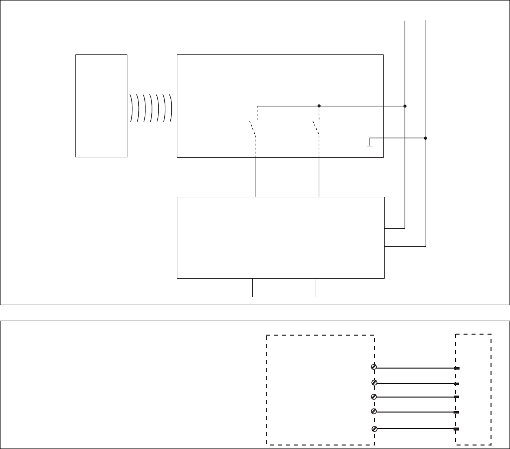
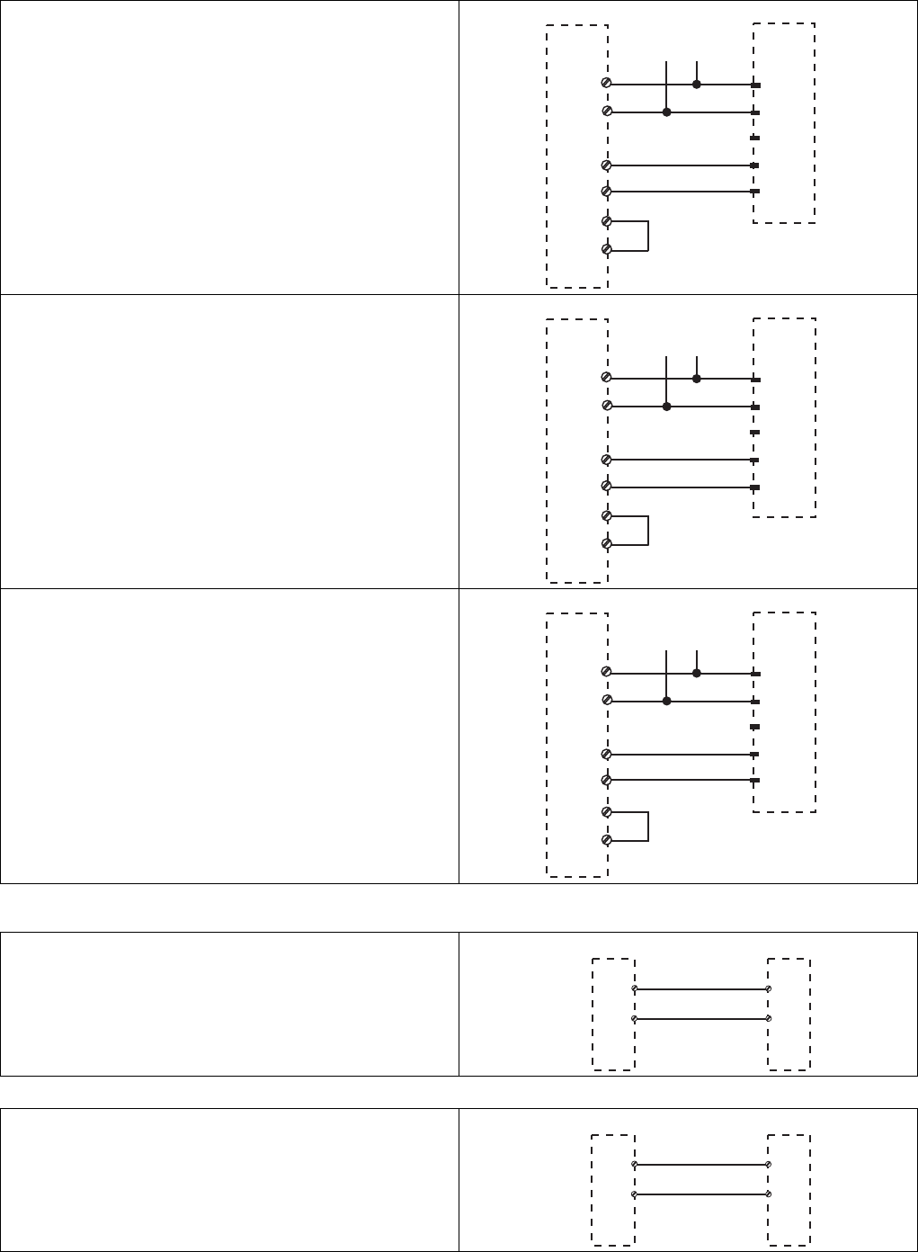
`Anschluss an PNOZmulti `Connection to PNOZmulti `Raccordement au PNOZmulti
`Anschluss an PSS `Connection to PSS `Raccordement au PSS
Einlernen des Betätigers
1175993995
Es wird jeder zugehörige Betätiger von Pilz (sie-
he Technische Daten) erkannt, sobald er in den
Ansprechbereich gebracht wird.
Teaching in the actuator
Any corresponding Pilz actuator (see Technical
Details) is detected as soon as it is brought into
the response range.
Programmation de l'organe de com-
mande par apprentissage
Chaque actionneur de Pilz (voir les caractéristi-
ques techniques) est détecté dès qu'il est entre
dans la zone de déclenchement.
PNOZ X10.1
PNOZ X10.11P
A1
A2
1
3
S12
Y3
2
4
5
24 V
0 V
A1
A2
12
22
n.c.
S21
S22
PNOZ PSENcode
PNOZ e1.1p
PNOZ e1vp
PNOZ e6.1p
PNOZ e6vp
A1
A2
1
3
S12
S22
2
4
5
24 V
0 V
A1
A2
12
22
n.c.
Y4
S11
PNOZ PSENcode
PNOZ e5.11p
PNOZ e5.13p
A1
A2
1
3
S12
S22
2
4
5
24 V
0 V
A1
A2
12
22
n.c.
Y37
S11
PNOZ PSENcode
Schutztür/safety gate/protecteur mobile
Schaltertyp 3/switchtype 3/type du capteure 3
I0, I1: Eingänge OSSD/inputs OSSD/entrées OSSD
I0
I1
12
weiss/white/blanc
schwarz/black/noir 22
PNOZmulti/PSS PSENcode
Schutztür/safety gate/protecteur mobile
Standardbaustein SB64/standard block SB64/bloc standard SB64
I0, I1: Eingänge/inputs/entrées
I0
I1
12
weiss/white/blanc
schwarz/black/noir 22
PNOZmulti/PSS PSENcode
- 7 -
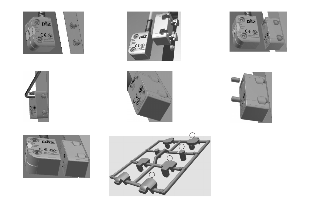
Montage
1086339595
`Montieren Sie Sicherheitsschalter und Betä-
tiger parallel gegenüberliegend.
ACHTUNG!
Eine Umgebung mit elektrisch oder magne-
tisch leitfähigem Material kann die Geräte-
eigenschaften beeinflussen. Prüfen Sie die
Schaltabstände und den gesicherten Ab-
schaltabstand.
`Befestigen Sie Sicherheitsschalter und Betä-
tiger ausschließlich mit Schrauben M4 mit
flacher Kopfunterseite (z.B. M4-Zylinder-
kopf- oder -Flachkopfschrauben).
INFO
Sichern Sie den Betätiger gegen unbefug-
tes Entfernen und vor Verschmutzung. Ver-
schließen Sie die Montageöffnungen mit
den mitgelieferten Verschlüssen.
INFO
Verschluss (1) entspricht den UL-Anforde-
rungen, Verschluss (4) entspricht nicht den
UL-Anforderungen.
`Anzugsdrehmoment max. 0,8 Nm.
`Beachten Sie unbedingt den Abstand zwi-
schen zwei Sicherheitsschaltern (siehe Tech-
nische Daten).
Sicherheitsschalter und Betätiger
`keinen starken Stößen oder Schwingungen
aussetzen
`nicht als Anschlag benutzen
Installation
`The safety switch and actuator should be in-
stalled opposite each other in parallel.
CAUTION!
The unit's properties may be affected if in-
stalled in an environment containing electri-
cally or magnetically conductive material.
Please check the operating distances and
the assured release distance.
`Safety switches and actuators should only
be secured using M4 screws with a flat head
(e.g. M4 cheese-head or pan head screws).
INFORMATION
The actuator should be protected from un-
authorised removal and from contamina-
tion. Close the mounting holes using the
seals provided.
INFORMATION
Seal (1) meets UL requirements; seal (4)
does not meet UL requirements.
`Torque setting max. 0.8 Nm.
`The distance between two safety switches
must be maintained (see Technical details).
Safety switches and actuators
`Should not be exposed to heavy shock or vi-
bration
`Should not be used as a limit stop
Montage
`Montez le capteur de sécurité et l'actionneur
l'un en face de l'autre de manière parallèle.
ATTENTION !
Un environnement avec des matériaux
conducteurs de l'électricité ou du magné-
tisme peut affecter les caractéristiques de
l'appareil. Veuillez vérifier les distances de
commutation et la distance de déclenche-
ment de sécurité.
`Pour fixer le capteur de sécurité et l'action-
neur, utilisez uniquement des vis M4 dont la
tête présente une face inférieure plate (par
ex. vis M4 cylindriques ou à tête plate).
INFORMATION
Assurez-vous que l'actionneur ne puisse
être ni retiré sans autorisation, ni encrassé.
Refermez les ouvertures du montage à
l'aide des fermetures fournies.
INFORMATION
La fermeture (1) correspond aux exigences
UL ; la fermeture (4) ne correspond aux
exigences UL.
`Couple de serrage max. 0,8 Nm.
`Veuillez absolument respecter la distance
entre les capteurs de sécurité (voir les carac-
téristiques techniques).
Le capteur de sécurité et l'actionneur
`ne doivent pas subir des chocs et vibrations
importants
`ne doivent pas être utilisés comme butée
- 8 -
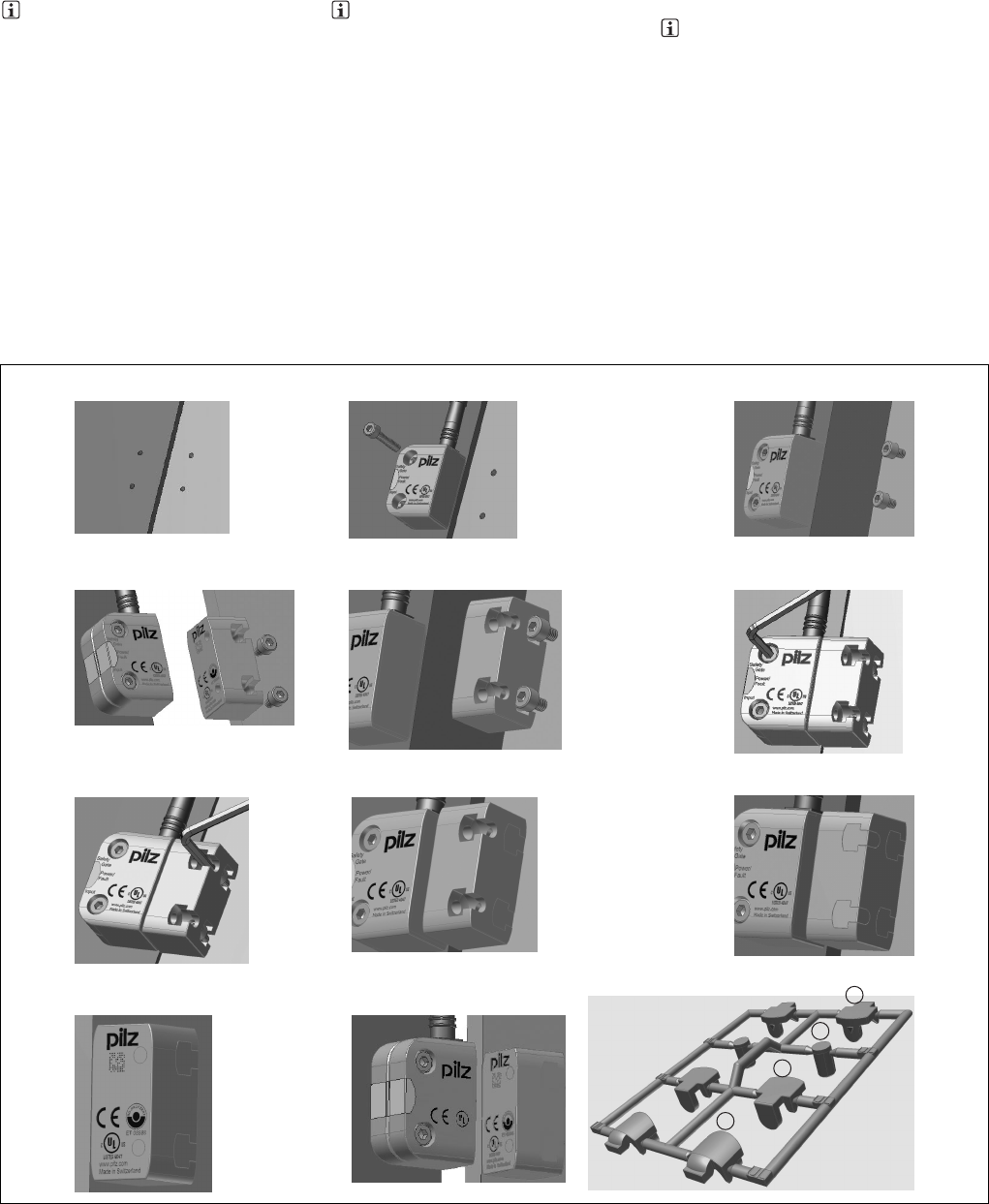
Montage Variante 1
1086268427
`1. Gewinde (M4) in gewünschter Position
schneiden.
`2. Sensor mit einer Schraube fixieren.
`3. Zweite Schraube in Sensor eindrehen.
(Wichtig: Schrauben nicht fest anziehen).
Schrauben für Betätiger eindrehen, dabei
den Abstand Schraubenkopf zur Auflage be-
achten: ca. 3 ... 6 mm.
`4. Betätiger zu Sensor ausrichten.
INFO
Die beschriftete Fläche des Betätigers (ak-
tive Fläche) muss zum Sensor zeigen.
`5. Betätiger auf die Schrauben schieben.
`6. Sensor ausrichten und die Schrauben mit
max. 0,8 Nm anziehen.
`7. Betätiger ausrichten und die Schrauben
mit max. 0,8 Nm anziehen.
`8. Verwendete Montageöffnungen mit Ver-
schluss (1) oder (4) schließen.
`9. Nicht verwendete Montageöffnungen mit
Verschluss (2) schließen.
`10. Montageöffnungen auf aktiver Fläche mit
Verschluss (3) schließen.
`11. Sensor und Betätiger sind fertig montiert.
Installation type 1
`1. Cut the thread (M4) in the required posi-
tion.
`2. Use a screw to fix the sensor.
`3. Attach the second screw to the sensor.
(Important: do not tighten the screws). Attach
the screws for the actuator, maintaining the
distance between the screw head and the
plate: ca. 3 ... 6 mm
`4. Align actuator to sensor.
INFORMATION
The inscribed area on the actuator (active
surface) must point to the sensor.
`5. Slide the actuator on to the screws.
`6. Align the sensor and tighten the screws to
a max. 0.8 Nm.
`7. Align the actuator and tighten the screws
to a max. 0.8 Nm.
`8. Close used mounting holes using seal (1)
or (4).
`9. Close unused mounting holes using seal
(2).
`10. Close mounting holes on the sensing
face using seal (3).
`11. Installation of sensor and actuator is now
complete.
Montage du modèle 1
`1. Couper le filetage (M4) dans la position
souhaitée.
`2. Fixer le capteur à l'aide d'une vis.
`3. Visser la deuxième vis dans le capteur.
(Important : ne pas serrer les vis à fond). Vis-
ser les vis pour l'actionneur, pour cela, res-
pecter la distance entre la tête de vis et
l'application : env. 3 à 6 mm
`4. Orienter l'actionneur par rapport au cap-
teur.
INFORMATION
La surface de l'actionneur avec une inscrip-
tion (surface active) doit être orientée vers
le capteur.
`5. Pousser l'actionneur sur les vis.
`6. Orienter le capteur et serrer les vis avec
max. 0,8 Nm.
`7. Orienter l'actionneur et serrer les vis avec
max. 0,8 Nm.
`8. Refermer les ouvertures destinées au
montage à l'aide des fermetures (1) ou (4).
`9. Refermer les ouvertures non utilisées pour
le montage à l'aide de la fermeture (2).
`10. Refermer les ouvertures destinées au
montage, situées sur la surface active, à
l'aide de la fermeture (3).
`11. Le capteur et l'actionneur sont à présent
montés.
13
2
46
5
79
8
10 11
1
2
3
4
- 9 -
Montage Variante 2
1086273035
Montieren Sie den Sensor wie bei Montage Va-
riante 1
`1. Schrauben für Betätiger eindrehen, dabei
den Abstand Schraubenkopf zur Auflage be-
achten: ca. 3 ... 6 mm.
`2. Nicht verwendete Montageöffnungen, die
auf der Auflagefläche aufliegen, mit Ver-
schluss (2) schließen.
`3. Betätiger auf die Schrauben schieben.
`4. Betätiger ausrichten und die Schrauben
mit max. 0,8 Nm anziehen.
`5. Verwendete Montageöffnungen mit Ver-
schluss (1) oder (4) schließen.
`6. Montageöffnungen auf aktiver Fläche mit
Verschluss (3) schließen.
`7. Sensor und Betätiger sind fertig montiert.
Installation type 2
Install the sensor as shown for installation type
1
`1. Attach the screws for the actuator, main-
taining the distance between the screw head
and the plate: ca. 3 ... 6 mm.
`2. Close unused mounting holes on the plate
using seal (2).
`3. Slide the actuator on to the screws.
`4. Align the actuator and tighten the screws
to a max. 0.8 Nm.
`5. Close used mounting holes using seal (1)
or (4).
`6. Close mounting holes on the sensing face
using seal (3).
`7. Installation of sensor and actuator is now
complete.
Montage du modèle 2
Montez le capteur de la même manière que
pour le modèle 1
`1. Visser les vis pour l'actionneur, pour cela,
respecter la distance entre la tête de vis et
l'application : env. 3 à 6 mm.
`2. Refermer à l'aide de la fermeture (2) les
ouvertures non utilisées pour le montage qui
se trouvent dans la surface d'application.
`3. Pousser l'actionneur sur les vis.
`4. Orienter l'actionneur et serrer les vis avec
max. 0,8 Nm.
`5. Refermer les ouvertures destinées au
montage à l'aide des fermetures (1) ou (4).
`6. Refermer les ouvertures destinées au
montage, situées sur la surface active, à
l'aide de la fermeture (3).
`7. Le capteur et l'actionneur sont à présent
montés.
Justage
1086401675
`Prüfen Sie die Funktion immer mit einem der
zugelassenen Auswertegeräte
`Die angegebenen Schaltabstände (siehe
technische Daten) gelten nur, wenn Sicher-
heitsschalter und Betätiger parallel gegen-
überliegend montiert sind. Andere
Anordnungen können zu abweichenden
Schaltabständen führen.
`Beachten Sie den maximal zulässigen Sei-
ten- und Höhenversatz (siehe "Schaltabstän-
de" und "Seiten- und Höhenversatz").
Adjustment
`Always test the function with one of the ap-
proved evaluation devices
`The stated operating distances (see Techni-
cal details) only apply when the safety switch
and actuator are installed facing each other
in parallel. Operating distances may deviate
if other arrangements are used.
`Note the maximum permitted lateral and ver-
tical offset (see "Operating distances" and
"Lateral and vertical offset").
Ajustement
`Vérifiez la fonction uniquement avec l'un des
appareils de contrôle homologués.
`Les distances de commutation mentionnées
dans les caractéristiques techniques sont
valables uniquement lorsque le capteur de
sécurité et l'actionneur sont montés l'un en
face de l'autre de manière parallèle. D'autres
montages peuvent conduire à des distances
de commutation divergentes.
`Respectez le décalage latéral et en hauteur
maximal autorisé (voir « Distances de
commutation » et « Décalage latéral et en
hauteur maximum »).
13
2
46
5
7
1
2
3
4
- 10 -
Betrieb
1176970891
Prüfen Sie vor der Inbetriebnahme die Funktion
des Sicherheitsschalters.
Statusanzeigen:
`LED "POWER/Fault" leuchtet grün: Gerät ist
betriebsbereit
`LED "Safety Gate" leuchtet gelb: Betätiger
befindet sich im Ansprechbereich
`LED "Input" leuchtet gelb: Gerät ist fehlerfrei
Fehleranzeige:
`LED "POWER/Fault" leuchtet rot: Fehlermel-
dung.
An den LEDS "Safety Gate" und "Input" wer-
den Blinkcodes zur Fehlerdiagnose ausge-
geben (siehe Technischer Katalog PSENmag
und PSENcode).
Abhilfe: Fehler beheben und Stromversor-
gung unterbrechen.
Operation
Check the function of the safety switch before
commissioning.
Status indicators:
`"POWER/Fault" LED lights up green: The unit
is ready for operation
`"Safety Gate" LED lights up yellow: Actuator
is within the response range
`"Input" LED lights up yellow: Device is error-
free
Fault indicator:
`"POWER/Fault" LED lights up red: Error
message.
Flashing codes for fault diagnostics are out-
put to the "Safety Gate" and "Input" LEDs
(see technical catalogue PSENmag and
PSENcode).
Remedy: Rectify fault and interrupt power
supply.
Utilisation
Vérifiez le fonctionnement du capteur de sécu-
rité avant sa mise en service.
Affichages des états :
`La LED « POWER/Fault » s'allume en vert :
l'appareil est prêt à fonctionner
`La LED « Safety Gate » s'allume en jaune :
l'actionneur se trouve dans la zone de détec-
tion
`La LED « Input » s'allume en jaune : l'appareil
ne présente aucun défaut
Affichage des erreurs :
`La LED « POWER/Fault » s'allume en rouge :
message d'erreur.
Des codes clignotants servant au diagnostic
des erreurs sont émis par les LEDs « Safety
Gate » et « Input » (voir le catalogue techni-
que PSENmag et PSENcode).
Remède : éliminer le défaut et couper l'ali-
mentation électrique.
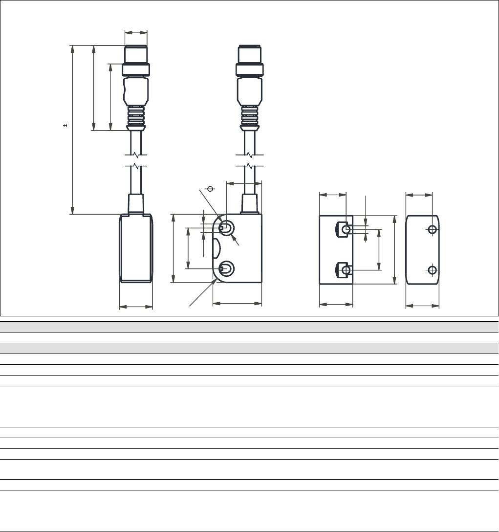
Abmessungen
1272150027
Dimensions Dimensions
Technische Daten Technical details Caractéristiques techniques
Elektrische Daten Electrical data Données électriques
Versorgungsspannung UBDC Supply voltage UB DC Tension d'alimentation UBDC 24 V
Spannungstoleranz Voltage tolerance Plage de la tension d'alimentation -20 %/+20 %
Leistungsaufnahme bei UBDC Power consumption at UB DC Consommation UBDC 1,0 W
Max. Einschaltstromimpuls Max. inrush current impulse Impulsion de courant max. lors de
la mise sous tension
A1 A1 A1 0,58 A
Impulsdauer Pulse duration Durée d'impulsion 1,0000 ms
Spannung an Eingängen Voltage at inputs Tension sur entrées 24 V DC
Strom pro Eingang Current per input Courant par entrée 5,0 mA
Schaltstrom pro Ausgang Switching current per output Intensité de commutation par sortie 100 mA
Schaltleistung pro Ausgang Breaking capacity per output Puissance de commutation par sor-
tie
2,4 W
Max. Schaltfrequenz Max. switch frequency Fréquence de commutation max. 3 Hz
Halbleiterausgänge (kurz-
schlussfest)
Semiconductor outputs (short cir-
cuit proof)
Sorties statiques (protégées contre
les courts-circuits)
Sicherheitsausgänge OSSD OSSD safety outputs Sorties de sécurité OSSD 2
Meldeausgänge Signal outputsSorties d'information1
14,4
37
4,5
22
18
12M
46,8
36
14,4
18
22
37
26,4
R8
8
19
Actuator
Safety switch
18
4,5
130 5

- 11 -
Max. Gesamtleitungswiderstand Rl-
max im Eingangskreis
Max. overall cable resistance Rlmax
in the input circuit
Résistance max. de l'ensemble du
câblage Rlmax dans le circuit d'en-
trée
1000 Ohm
Max. Leitungskapazität an den Si-
cherheitsausgängen
Max. line capacitance at the safety
outputs
Capacité max. du câblage sur les
sorties de sécurité
Leerlauf, PNOZ mit Relaiskontakten No-load, PNOZ with relay contacts Fonctionnement à vide, PNOZ avec
contacts de relais
400 nF
PNOZmulti, PNOZelog, PSS PNOZmulti, PNOZelog, PSS PNOZmulti, PNOZelog, PSS 400 nF
Zeiten Times Temporisations
Überbrückung bei Spannungsein-
brüchen
Supply interruption before deener-
gisation
Tenue aux micro-coupures 10,0 ms
Einschaltverzögerung Switch-on delay Temps de montée
nach Anlegen von UBafter applying UBaprès application de UB1,0 s
Eingänge typ. Input typ. Entrées env. 13 ms
Eingänge max. Input max. Entrées max. 20 ms
Betätiger typ. Actuator typ. Actionneur env. 45 ms
Betätiger max. Actuator max. Actionneur max. 120 ms
Rückfallverzögerung Delay-on de-energisation Temps de retombée
Eingänge typ. Input typ. Entrées env. 15 ms
Eingänge max. Input max. Entrées max. 20 ms
Betätiger typ. Actuator typ. Actionneur env. 40 ms
Betätiger max. Actuator max. Actionneur max. 260 ms
Testimpulsdauer Sicherheitsaus-
gänge
Test pulse duration on safety out-
puts
Durée du test impulsionnel pour les
sorties de sécurité
300 µs
Gleichzeitigkeit Kanal 1 und 2 Simultaneity, channel 1 and 2 Simultanéité des canaux 1 et 2 ∞
Umweltdaten Environmental data Données sur l'environnement
EMV EMC CEM EN 55011: class A,
EN 61000-4-2, EN 61000-4-3,
EN 61000-4-4, EN 61000-4-6,
EN 61000-4-8
Schockbeanspruchung Shock stress Résistance aux chocs 30g , 18 ms
Schwingungen nach EN 60947-5-2 Vibration to EN 60947-5-2 Vibrations selon EN 60947-5-2
Frequenz Frequency Fréquence 10 - 55 Hz
Amplitude Amplitude Amplitude 0,35 mm
Verschmutzungsgrad Pollution degree Niveau d'encrassement 3
Bemessungsisolationsspannung Rated insulation voltage Tension assignée d'isolement 75 V
Bemessungsstoßspannungsfestig-
keit
Rated impulse withstand voltage Tension assignée de tenue aux
chocs
1,00 kV
Überspannungskategorie Overvoltage category Catégorie de surtensions III
Umgebungstemperatur Ambient temperature Température d'utilisation -25 - 70 °C
Lagertemperatur Storage temperature Température de stockage -25 - 70 °C
Mechanische Daten Mechanical data Données mécaniques
Hysterese typ. Hysteresis typ. Hystérésis env. 2,0 mm
Gesicherter Schaltabstand Sao Assured operating distance Sao Distance de commutation de sécu-
rité Sao
8,0 mm
Gesicherter Ausschaltabstand Sar Assured release distance Sar Distance de déclenchement de sé-
curité Sar
20 mm
Typischer Schaltabstand SoTypical switching distance SoDistance de commutation caracté-
ristique So
11,0 mm
Ausschaltabstand SrRelease distance SrDistance de déclenchement Sr14,0 mm
Min. Abstand zwischen Sicherheits-
schaltern
Min. distance between safety
switches
Distance minimale entre les cap-
teurs de sécurité
10 cm
Zugehörige Betätiger Corresponding actuator Actionneurs correspondants PSEN cs3.1
Anschlussart Connection type Type de connection M12, 5-pol. Stiftstecker (male),
Connector male 5 pin M12,
Connecteur mâle M12 à 5 bro-
ches
Leitung Cable Câble LiYY 8 x 0,14 mm2
Schutzart Protection type Indice de protection IP67
Material Material Matériau
Gehäuse Housing Boîtier PBT
Abmessungen Dimensions Dimensions
Sensor Sensor Capteur
Höhe Height Hauteur 37,0 mm
Breite Width Largeur 26,0 mm
Tiefe Depth Profondeur 18,0 mm
Betätiger Actuator Actionneur
Höhe Height Hauteur 37 mm
Breite Width Largeur 18 mm
Tiefe Depth Profondeur 18 mm
Elektrische Daten Electrical data Données électriques
Originalbetriebsanleitung/Original instructions/Notice originale
22172-3FR-01, 2011-02 Printed in Germany Printed in Germany
22172-3FR-012011-02Printed in Germ any
Gewicht Weight Poids
Sensor Sensor Capteur 35 g
Betätiger Actuator Actionneur 15 g
Sicherheitstechnische Kennda-
ten Safety-related characteristic
data Caractéristiques techniques de
sécurité
PL nach EN ISO 13849-1: 2006 PL in accordance with EN ISO
13849-1: 2006 PL selon EN ISO 13849-1: 2006 PL e (Cat. 4)
Kategorie nach EN 954-1 Category in accordance with EN
954-1 Catégorie selon EN 954-1 Cat. 4
SIL CL nach EN IEC 62061 SIL CL in accordance with EN IEC
62061 SIL CL selon EN IEC 62061 SIL CL 3
PFH nach EN IEC 62061 PFH in accordance with EN IEC
62061 PFH selon EN IEC 62061 2,62E-09
SIL nach IEC 61511 SIL in accordance with IEC 61511 SIL selon IEC 61511 SIL 3
PFD nach IEC 61511 PFD in accordance with IEC 61511 PFD selon IEC 61511 7,68E-05
tM in Jahren tM in years tM en années 20
Es gelten die 2009-01 aktuellen Ausgaben der
Normen.
The standards current on 2009-01 apply. Les versions actuelles 2009-01 des normes
s'appliquent.
Bestelldaten Order reference Références
Typ/Type/Type Stück/
Quantity/
Nombre
Wirkweise/Operation/Ac-
tionnement Merkmale/Features/ Caractéri-
stiques Bestell-Nr./Order
no./Référence
PSEN cs3.1n/PSEN cs3.1 1/1 Transpondertechnik/Trans-
ponder technology/Technique
à transpondeur
Sicheres Schutztürsystem, codiert/
Safety gate system, coded/Système
de sécurité pour protecteurs mobi-
les, codé
541 003
PSEN cs3.1n (switch) 1 Transpondertechnik/Trans-
ponder technology/Technique
à transpondeur
Sicherheitsschalter, codiert/Safety
switch, coded/Capteur de sécurité,
codé
541 053
PSEN cs3.1 1 Transpondertechnik/Trans-
ponder technology/Technique
à transpondeur
Betätiger, codiert/Actuator, coded/
Actionneur, codé
541 080
EG-Konformitätserklärung
1139424011
Diese(s) Produkt(e) erfüllen die Anforderungen
der Richtlinie 2006/42/EG über Maschinen des
europäischen Parlaments und des Rates. Die
vollständige EG-Konformitätserklärung finden
Sie im Internet unter www.pilz.com.
Bevollmächtigter: Norbert Fröhlich, Pilz GmbH
& Co. KG, Felix-Wankel-Str. 2, 73760 Ostfil-
dern, Deutschland
EC Declaration of Conformity
This (these) product(s) comply with the require-
ments of Directive 2006/42/EC of the European
Parliament and of the Council on machinery.
The complete EC Declaration of Conformity is
available on the Internet at www.pilz.com.
Authorised representative: Norbert Fröhlich,
Pilz GmbH & Co. KG, Felix-Wankel-Str. 2,
73760 Ostfildern, Germany
Déclaration de conformité CE
Ce(s) produit(s) satisfait (satisfont) aux exigen-
ces de la directive 2006/42/CE relative aux ma-
chines du Parlement Européen et du Conseil.
Vous trouverez la déclaration de conformité CE
complète sur notre site internet www.pilz.com.
Représentant : Norbert Fröhlich, Pilz GmbH &
Co. KG, Felix-Wankel-Str. 2, 73760 Ostfildern,
Allemagne
Mechanische Daten Mechanical data Données mécaniques