Pilz and KG PSENCS5 RFID Proximity switch User Manual Manual part1
Pilz GmbH & Co. KG RFID Proximity switch Manual part1
Contents
- 1. Manual part1
- 2. Manual part2
Manual part1

PSENcs5.1p
OperatingManual1003418EN01
PSENsensortechnology

Preface
Thisdocumentistheoriginaldocument.
AllrightstothisdocumentationarereservedbyPilzGmbH&Co.KG.Copiesmaybemade
forinternalpurposes.Suggestionsandcommentsforimprovingthisdocumentationwillbe
gratefullyreceived.
Pilz®,PIT®,PMI®,PNOZ®,Primo®,PSEN®,PSS®,PVIS®,SafetyBUSp®,
SafetyEYE®,SafetyNETp®,thespiritofsafety®areregisteredandprotectedtrademarks
ofPilzGmbH&Co.KGinsomecountries.
SDmeansSecureDigital

Content
OperatingManualPSENcs5.1p
1003418EN01 3
Introduction 5
Validityofdocumentation 5
Usingthedocumentation 5
Definitionofsymbols 5
Safety 6
Intendeduse 6
Safetyregulations 6
Safetyassessment 6
Useofqualifiedpersonnel 7
Warrantyandliability 7
Disposal 7
Foryoursafety 8
Unitfeatures 8
Functiondescription 8
Blockdiagram 9
Operatingdistances 10
Lateraloffsetwhenaligningtothetriangleorsquaremarking 11
Verticaloffsetwhenaligningtothetriangleorsquaremarking 12
Lateralandverticaloffsetwhenaligningtothesemicirclemarking 13
Wiring 14
Pinassignment,connectorandcable 14
Connectiontoevaluationdevices 15
Teachingintheactuator 18
Installation 18
Adjustment 21
Operation 21
Normalmode 22
Errordisplay 22
Dimensionsinmm 23
Technicaldetails 24
Safetycharacteristicdata 27
Supplementarydata 27
Radioapproval 27
Orderreference 27
System 27

PSENcs5.1p
OperatingManualPSENcs5.1p
1003418EN01 5
Introduction
Validityofdocumentation
ThisdocumentationisvalidfortheproductPSENcs5.1p.Itisvaliduntilnewdocumentation
ispublished.
Thisoperatingmanualexplainsthefunctionandoperation,describestheinstallationand
providesguidelinesonhowtoconnecttheproduct.
Usingthedocumentation
Thisdocumentisintendedforinstruction.Onlyinstallandcommissiontheproductifyou
havereadandunderstoodthisdocument.Thedocumentshouldberetainedforfutureref
erence.
Definitionofsymbols
Informationthatisparticularlyimportantisidentifiedasfollows:
DANGER!
Thiswarningmustbeheeded!Itwarnsofahazardoussituationthatposes
animmediatethreatofseriousinjuryanddeathandindicatespreventive
measuresthatcanbetaken.
WARNING!
Thiswarningmustbeheeded!Itwarnsofahazardoussituationthatcould
leadtoseriousinjuryanddeathandindicatespreventivemeasuresthatcan
betaken.
CAUTION!
Thisreferstoahazardthatcanleadtoalessseriousorminorinjuryplus
materialdamage,andalsoprovidesinformationonpreventivemeasures
thatcanbetaken.
NOTICE
Thisdescribesasituationinwhichtheproductordevicescouldbedam
agedandalsoprovidesinformationonpreventivemeasuresthatcanbe
taken.Italsohighlightsareaswithinthetextthatareofparticularimport
ance.
PSENcs5.1p
OperatingManualPSENcs5.1p
1003418EN01 6
INFORMATION
Thisgivesadviceonapplicationsandprovidesinformationonspecialfea
tures.
Safety
Intendeduse
Thesafetyfunctionsofthesafetyswitchare:
}safedetectionofthepresenceoftheactuator
}2safetyinputsforseriesconnectionofmultiplesafetysensors
}2safetyoutputs,eachofwhichsupplyahighsignalwhenthecorrespondinginputis
highandtheactuatorisintheswitch'sresponserange.
Thesafetyswitchmeetstherequirementsinaccordancewith:
}EN6094753withtheactuatorPSENcs5.1:PDDB
}EN62061:SILCL3
}ENISO138491:PLeCat.4
}ENISO14119
ThesafetyswitchmayonlybeusedwiththecorrespondingactuatorPSENcs5.1.
ThesafetylevelPLe(Cat.4)/SILCL3isonlyachievedif
}thesafetyoutputsuse2channelprocessing.
Thefollowingisdeemedimproperuseinparticular:
}Anycomponent,technicalorelectricalmodificationtotheproduct
}Useoftheproductoutsidetheareasdescribedinthismanual
}Useoftheproductoutsidethetechnicaldetails(seechapterentitled"TechnicalDe
tails").
NOTICE
EMCcompliantelectricalinstallation
Theproductisdesignedforuseinanindustrialenvironment.Theproduct
maycauseinterferenceifinstalledinotherenvironments.Ifinstalledinother
environments,measuresshouldbetakentocomplywiththeapplicable
standardsanddirectivesfortherespectiveinstallationsitewithregardtoin
terference.
Safetyregulations
Safetyassessment
Beforeusingaunititisnecessarytoperformasafetyassessmentinaccordancewiththe
MachineryDirective.

PSENcs5.1p
OperatingManualPSENcs5.1p
1003418EN01 7
Functionalsafetyisguaranteedfortheproductasasinglecomponent.However,thisdoes
notguaranteethefunctionalsafetyoftheoverallplant/machine.Inordertoachievethere
quiredsafetylevelfortheoverallplant/machine,definethesafetyrequirementsforthe
plant/machineandthendefinehowthesemustbeimplementedfromatechnicalandorgan
isationalstandpoint.
Useofqualifiedpersonnel
Theproductsmayonlybeassembled,installed,programmed,commissioned,operated,
maintainedanddecommissionedbycompetentpersons.
Acompetentpersonissomeonewho,becauseoftheirtraining,experienceandcurrentpro
fessionalactivity,hasthespecialistknowledgerequiredtotest,assessandoperatethe
workequipment,devices,systems,plantandmachineryinaccordancewiththegeneral
standardsandguidelinesforsafetytechnology.
Itisthecompany’sresponsibilityonlytoemploypersonnelwho:
}Arefamiliarwiththebasicregulationsconcerninghealthandsafety/accidentpreven
tion
}Havereadandunderstoodtheinformationprovidedinthisdescriptionunder"Safety"
}Andhaveagoodknowledgeofthegenericandspecialiststandardsapplicabletothe
specificapplication.
Warrantyandliability
Allclaimstowarrantyandliabilitywillberenderedinvalidif
}Theproductwasusedcontrarytothepurposeforwhichitisintended
}Damagecanbeattributedtonothavingfollowedtheguidelinesinthemanual
}Operatingpersonnelarenotsuitablyqualified
}Anytypeofmodificationhasbeenmade(e.g.exchangingcomponentsonthePCB
boards,solderingworketc.).
Disposal
}Insafetyrelatedapplications,pleasecomplywiththemissiontimeTMinthesafetyre
latedcharacteristicdata.
}Whendecommissioning,pleasecomplywithlocalregulationsregardingthedisposalof
electronicdevices(e.g.ElectricalandElectronicEquipmentAct).
PSENcs5.1p
OperatingManualPSENcs5.1p
1003418EN01 8
Foryoursafety
DANGER!
Risktolifeduetomanipulation/defeatofthesafeguard
Ifreplacementactuatorsareobtained,thesemustbeinstalledasdescribed
inthechapterentitledInstallation[ 18].
Ifreplacementactuatorsareusedmanipulativelyorthefunctionofthesafe
guardisdefeated,thereisarisktolifewhenoperatingtheplantormachine!
Thismustbeconsideredintheoperator'shazardassessmentandtheoper
atormustdefineappropriatemeasurestoexcludemanipulation.
}Donotremovetheprotectivecapuntilyouarejustabouttoconnecttheunit.Thiswill
preventpotentialcontamination.
Unitfeatures
}Transpondertechnologyforpresencedetection(safetyfunction)
}Coding:coded(measuretominimisedefeatpossibilitiesinaccordancewithISO14119)
}Dualchanneloperation
}2safetyinputsforseriesconnectionofmultiplesafetyswitches
}2safetyoutputs
}1signaloutput
}LEDdisplayfor:
– Stateoftheactuator
– Stateoftheinputs
– Supplyvoltage/fault
}4actuationdirections,eachwith3approachdirections(seeExplanationof
markings[ 10])
– Squaremarkingfornormaloperatingdistance
– Trianglemarkingforshortoperatingdistance
– 2semicirclemarkingsforalateralapproach.PleasenotetheLateralandvertical
offsetwiththelateralapproachtothesemicirclemarking.
Theguaranteedsafeoperatingdistancesonlyapplywhentheactuatorapproachesthe
switchvertically.Withtheotherapproachdirections,theoperatingdistancesmay
sometimesbeconsiderablylarger(particularlywhenapproachingthesemicircle).
Functiondescription
Thesafetyoutputsmayhaveahighorlowsignal,dependingonthepositionoftheactuator
andthesignalstatusofthesafetyinputs.
PSENcs5.1p
OperatingManualPSENcs5.1p
1003418EN01 9
Electricalstatesofthesafetyinputsandoutputs(whenswitchisreadyforoperation:
DEVICELEDisgreen):
Actuatorin
there
sponse
range
Safetyinput
S11
Safetyinput
S21
Safetyout
put12
Safetyout
put22
Signalout
putY32
Yes High High High High High
Yes Low Low Low Low High
No X X Low Low Low
Yes High Low High Low High
Yes Low High Low High High
x:Highorlowsignal
FeasibilitymonitoringforsafetyinputsS11andS21
}Ifonesafetyinputswitchesfromhightolow,whiletheothersafetyinputremainshigh,
anunequalstatusisdisplayed:InputLEDhasquickyellowflashesandDeviceLED
flashesred
}Ifthissafetyinputswitchesbackfromlowtohigh,whiletheothersafetyinputremains
high,afeasibilityerrorisdisplayedandapartialoperationlockistriggered:InputLED
flashesyellowandDeviceLEDflashesred
Aswitchtoahighsignalwillonlyleadtonormalswitchoperationifbothinputshadalow
signal.Fromthismomenton,theswitchtohighmayoccur(partialoperationlockseeError
display[ 22]).
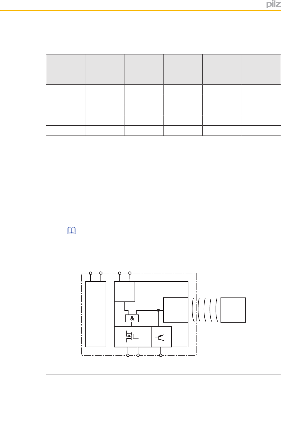
Blockdiagram
A1 A2 S11 S21
12 22 Y32
Power
Input
Receiver Actuator
PSENcs5.1p
OperatingManualPSENcs5.1p
1003418EN01 10
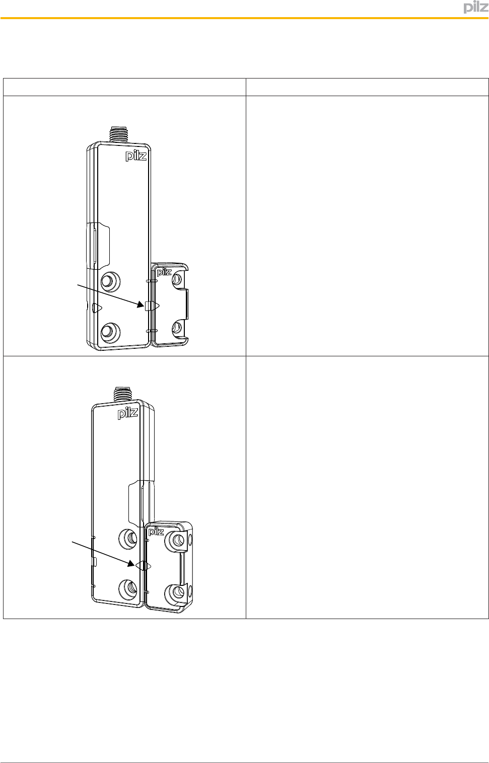
Operatingdistances
Alignmentoftheactuator Operatingdistances
[1]Actuatoralignedtothesquaremarkingonthe
switch
[1]
DEVICE
INPUT
SAFETY GATE
SaoAssuredoperatingdistance:8mm
SoTypicaloperatingdistance:11mm
SrTypicalreleasedistance:14mm
SarAssuredreleasedistance:20mm
[2]Actuatoralignedtothetrianglemarkingonthe
switch
[2]
DEVICE
INPUT
SAFETY GATE
SaoAssuredoperatingdistance:4mm
SoTypicaloperatingdistance:5mm
SrTypicalreleasedistance:8mm
SarAssuredreleasedistance:12mm
PSENcs5.1p
OperatingManualPSENcs5.1p
1003418EN01 11
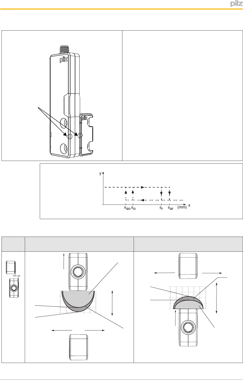
[3]Actuatoralignedtothesemicirclemarkingonthe
switch
[3]
DEVICE
INPUT
SAFETY GATE
SaoAssuredoperatingdistance:6mm
SoTypicaloperatingdistance:9mm
SrTypicalreleasedistance:11mm
SarAssuredreleasedistance:19mm
On
Off
Lateraloffsetwhenaligningtothetriangleorsquaremarking
Alignment1:Actuatoralignedtothesquare
markingontheswitch
Alignment2:Actuatoralignedtothetriangle
markingontheswitch
[1]
[2]
[3]
[4] [4]
[5]
[6]
8
4
0
12
14
4
8
12
14
-12 -8 -4 0 1284
8
4
0
12
14
[7]
[1]
[2]
[3]
[4] [4]
[5]
[6]
8
4
0
12
-8 -4 0 84
8
4
0
12
-12 12
[7]
PSENcs5.1p
OperatingManualPSENcs5.1p
1003418EN01 12
Legend:
}[1]:Hysteresis
}[2]:TypicaloperatingdistanceSO
}[3]:TypicalreleasedistanceSr
}[4]:Offsetinmm
}[5]:Operatingdistanceinmm
}[6]:Responserange
}[7]:StatusofLED
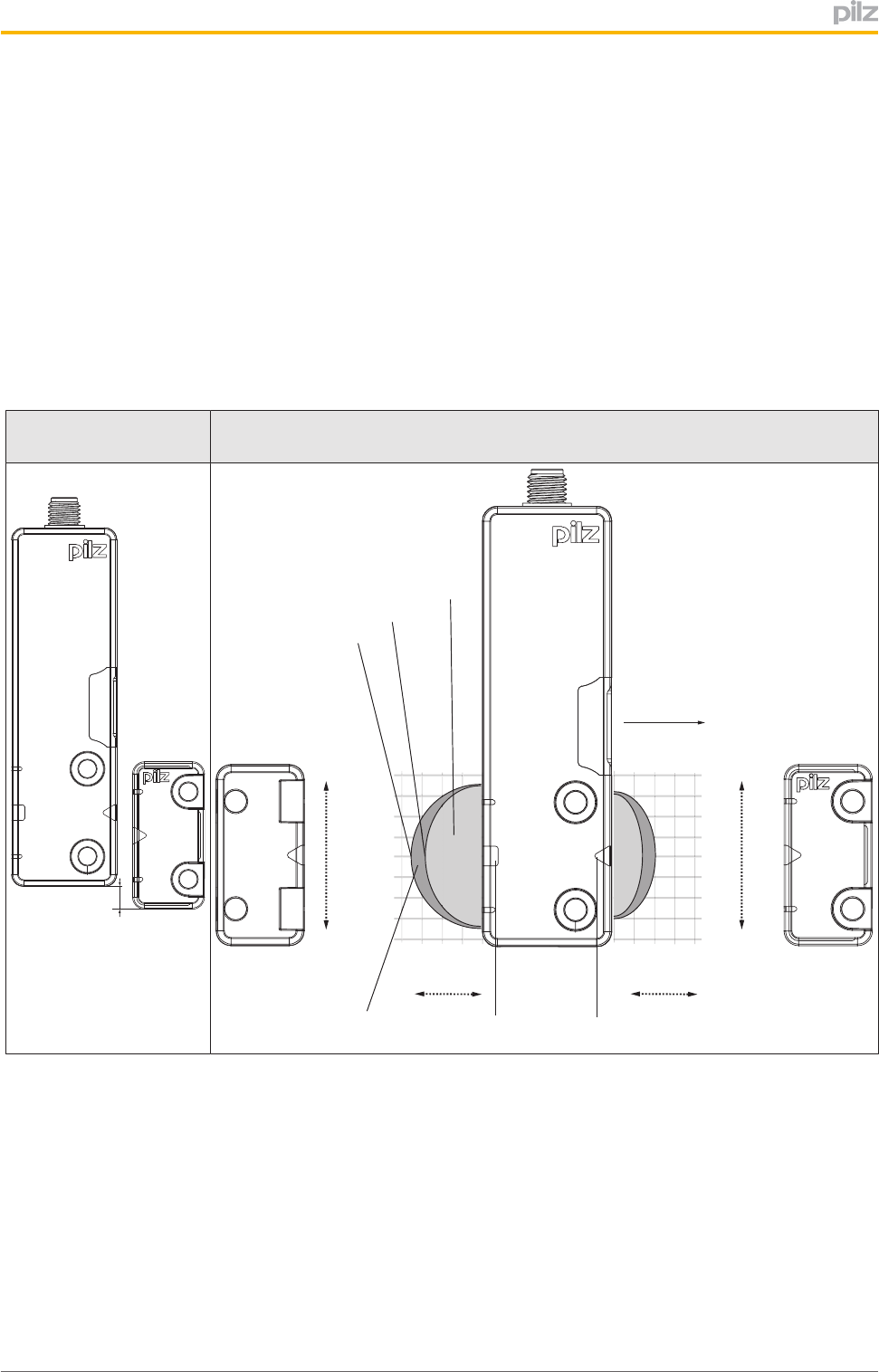
Verticaloffsetwhenaligningtothetriangleorsquaremarking
Alignment1/2:Actuatoralignedtothetriangleorsquaremarkingonthe
switch
DEVICE
INPUT
SAFETY GATE
[4]
[5]
[8] [9]
[1]
[3]
[2]
840
-12
-8
-4
0
12
8
4
840
-12
-8
-4
0
12
8
4
12 16
840 12 16
16
-16
[4]
1216
8 4 012
16
-16
16
[6]
[5]
[7]
DEVICE
INPUT
SAFETY GATE
Legend
}[1]:Hysteresis
}[2]:TypicaloperatingdistanceSO
}[3]:TypicalreleasedistanceSr
}[4]:Offsetinmm
}[5]:Operatingdistanceinmm
}[6]:Responserange
}[7]:StatusofLED
}[8]:Squaremarking
PSENcs5.1p
OperatingManualPSENcs5.1p
1003418EN01 13
}[9]:Trianglemarking
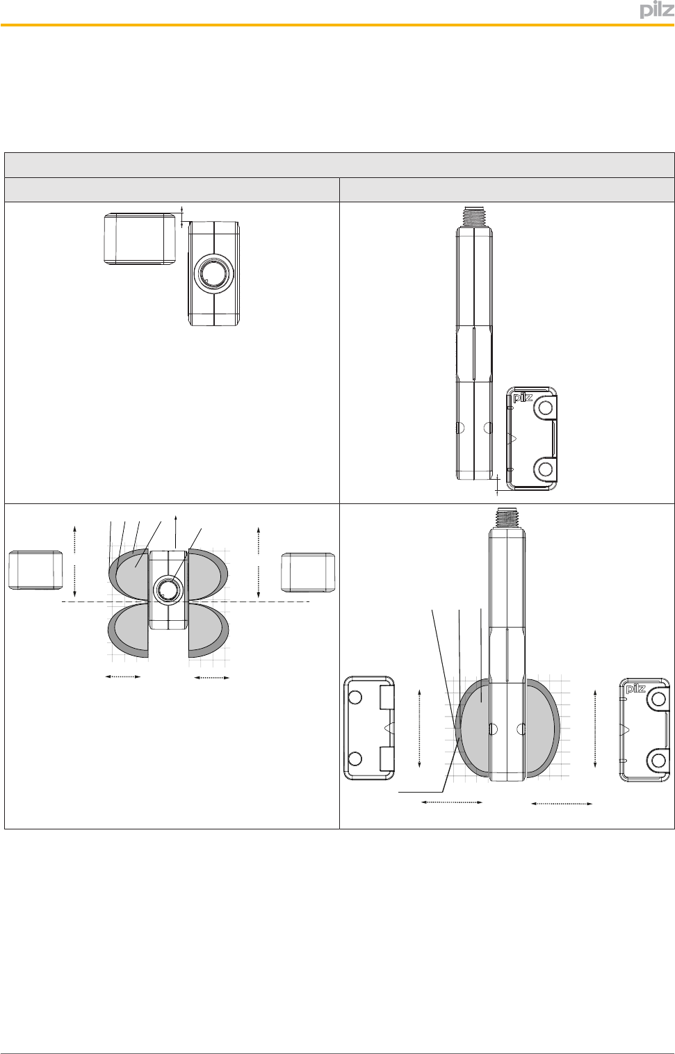
Lateralandverticaloffsetwhenaligningtothesemicirclemarking
Alignment3:Actuatoralignedtothesemicirclemarkingontheswitch
Lateraloffset Verticaloffset
[7]
[8]
[1][2]
[3] [6]
[4]
[4]
[5]
8
4
0
-4
-8
-12
-16
-20
-24
-28
12 8 4 0
[9]
8
4
0
-4
-8
-12
-16
-20
-24
-28
[5]
1284
0
[4]
[4]
[4] [4]
[1]
[3]
[5]
[6]
[2]
8 4 012
-12
-8
-4
0
12
8
4
8 4 012
16
-16
840 12
-12
-8
-4
0
12
8
4
16
-16
840 12
[5]
Twoactuatorsareshowninthediagramsbecausethesensorcanbeapproachedfrom
bothsidesatthesemicirclemarking.However,onlyoneactuatorcanbeused.
Legend
}[1]:Hysteresis
}[2]:TypicaloperatingdistanceSO
}[3]:TypicalreleasedistanceSr
}[4]:Offsetinmm
}[5]:Operatingdistanceinmm
PSENcs5.1p
OperatingManualPSENcs5.1p
1003418EN01 14
}[6]:Responserange
}[7]:Connectoronthesensor
}[8]:Limitofresponserange,positionofgatehinge
}[9]:StatusofLED
Wiring
Pleasenote:
}Informationgiveninthe"Technicaldetails"mustbefollowed.
}Themax.cablelengthlmaxintheinputcircuitiscalculatedfrom
– themax.cablecapacitanceatthesafetyoutputs(seeTechnicaldata[ 24]).
– theminimumpermittedsupplyvoltageatthesensor(19.2V).
}Thepowersupplymustmeettheregulationsforextralowvoltageswithprotectivesep
aration(SELV,PELV).
}Theinputsandoutputsofthesafetyswitchmusthaveaprotectiveseparationto
voltagesover60VDC.
INFORMATION
Onlyusesafetyrelayswitha24VDCsupplyvoltage.Safetyrelayswithuni
versalpowersupplyorinACdeviceversionshaveinternalpotentialisola
tionandarenotsuitableasevaluationdevices.
CAUTION!
Donotconnectthesignaloutputto0V!
IfthesignaloutputY32isconnectedto0V,thesafetyswitchmaybedam
agedasaresult.ConnectthesignaloutputY32toaconsumer,e.g.tothe
inputonacontrolsystem,orleavethesignaloutputunconnected.
}Thesupplyvoltagetothesafetyswitchmustbeprotectedwitha2Ato4Aquickacting
fuse.
}EnsuretheEMCrequirementsofIEC602041aremet.
}Whenconnectinginseries,makesureyoucomplywiththewiringtechnologyrequire
ments(DINEN602041)andmanipulationprotectionrequirements(ENISO14119).
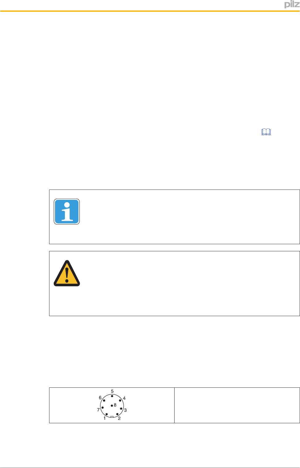
Pinassignment,connectorandcable
8pinM8/M12connector
PSENcs5.1p
OperatingManualPSENcs5.1p
1003418EN01 15
PIN
Pin
designation Function Wirecolour
1 S21 Input,channel2 white
2 A1 +24VUB brown
3 12 Output,channel1 Green
4 22 Output,channel2 yellow
5 Y32 Signaloutput grey
6 S11 Input,channel1 Pink
7 A2 0VUB blue
8 Donotconnect red
ThewirecolouralsoappliesforthecableavailablefromPilzasanaccessory.
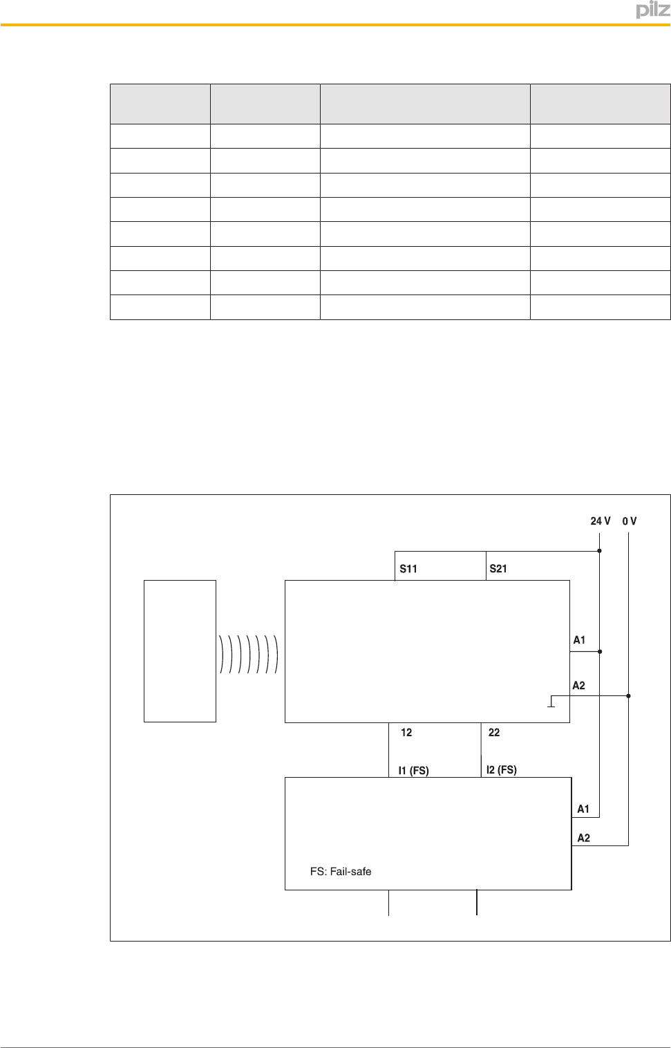
Connectiontoevaluationdevices
Makesurethattheselectedevaluationdevicehasthefollowingproperties:
}Dualchannelwithfeasibilitymonitoring
}OSSDsignalsareevaluated
Connectiondiagram,singleconnection
Actuator Receiver
Evaluation device
PSENcs5.1p
OperatingManualPSENcs5.1p
1003418EN01 16
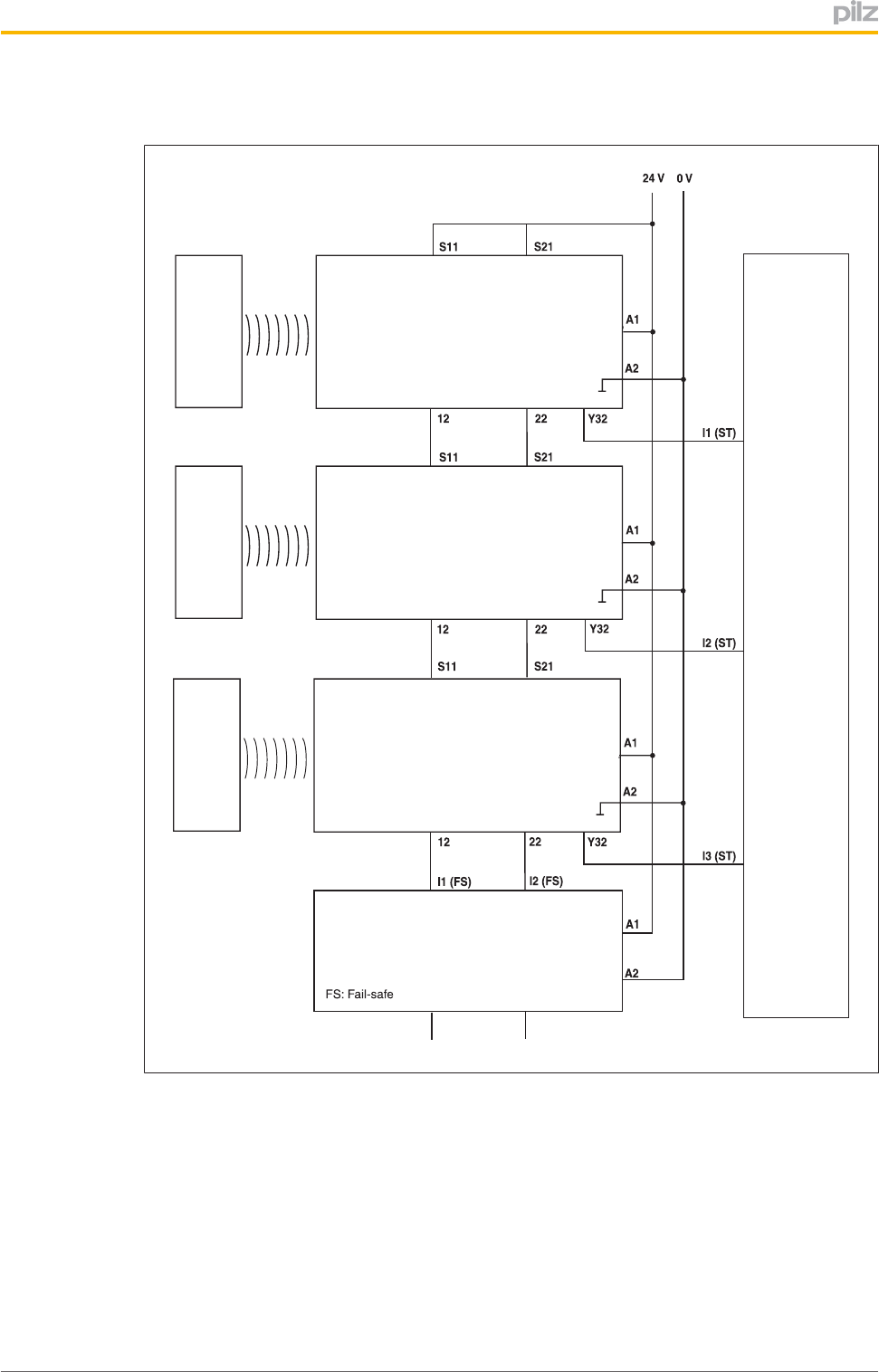
Connectiondiagram,seriesconnection
Actuator
Actuator
Control system
Evaluation device
Receiver
Receiver
ReceiverActuator
PSENcs5.1p
OperatingManualPSENcs5.1p
1003418EN01 17
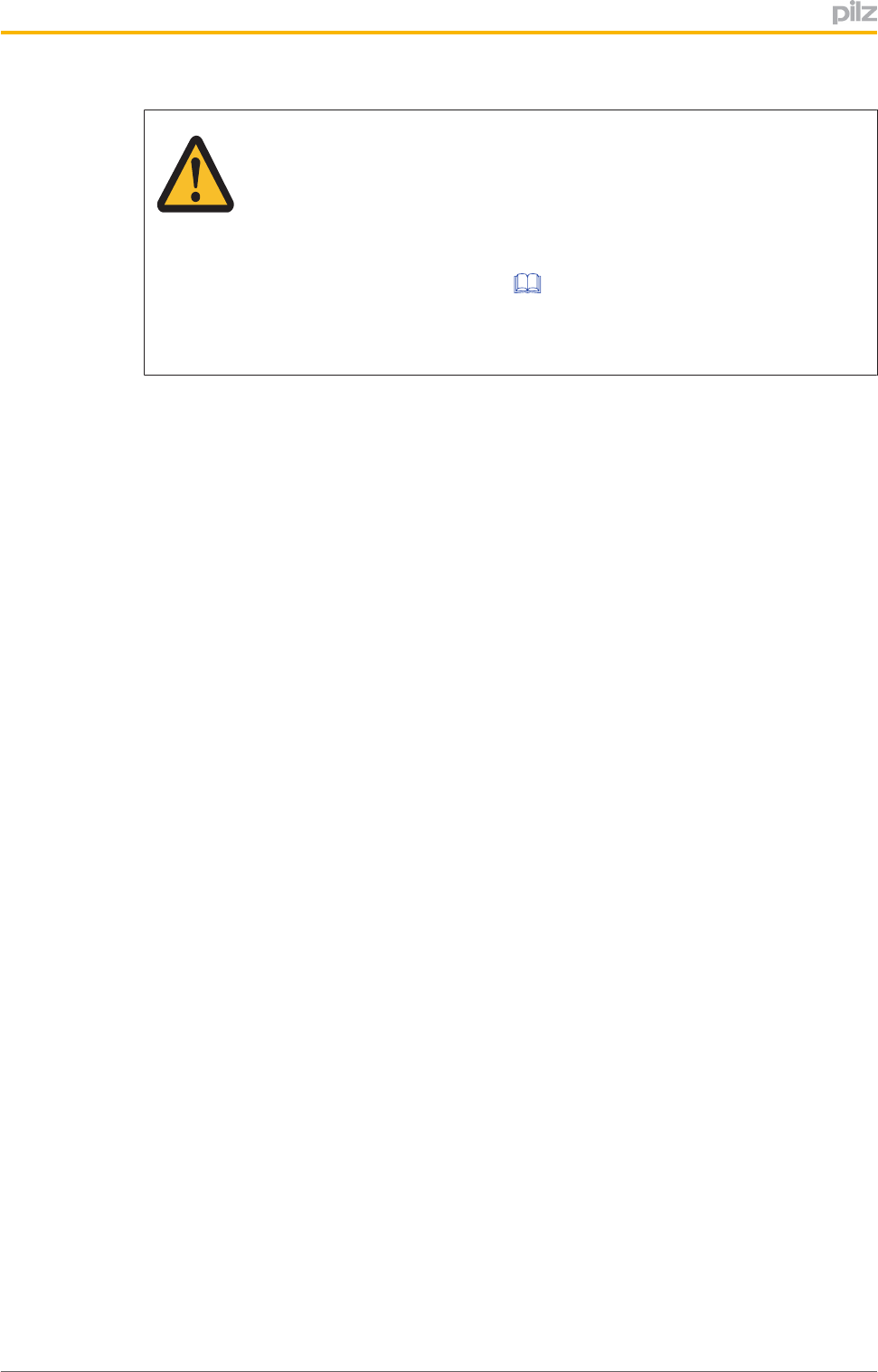
CAUTION!
Extensionofdelayondeenergisation
Whenseveral(n)devicesareconnectedinseries,thedelayondeener
gisationtimeaddswiththenumberofinterconnectedsafetyswitches.
Themax.delayondeenergisationismadeupofthe
risktime(seeTechnicaldetails[ 24])
+(n1)xmax.delayondeenergisationoftheinputs
+max.delayondeenergisationoftheevaluationdevice
ThesafetysensorsPSENcodearealsosuitableforseriesconnectionwithothersensors.
Theseriesconnectionofmaximum32sensorsPSENcs5.xandPSEN6.xisapprovedfor
SILCL3.
Inpractice,themaximumpossiblenumberwillbelimitedbythefollowingparameters,
amongothers:
}TherequiredSILlevel(e.g.SILCL3),
}TherequiredPerformanceLevel(e.g.Cat.4/PLe),
}Themaximumdelayorrisktimepermittedbytheapplication.
It'simportanttoensurethereissufficientsupplyvoltage,takinginrushcurrentsandfusing
intoconsideration.
ConnectiontoPilzevaluationdevices
ThesafetyswitchPSENcs5.1pcanbeconnectedtoPilzevaluationdevices,forexample.
MakesurethatanevaluationdeviceisselectedthatcanevaluateOSSDsignalsthrough
twochannels.
SuitablePilzevaluationdevicesare,forexample:
}PNOZelogforsafetygatemonitoring
}PNOZpowerforsafetygatemonitoring
}PNOZsigmaforsafetygatemonitoring
}PNOZXforsafetygatemonitoring
}PNOZmultiforsafetygatemonitoring
ConfiguretheswitchinthePNOZmultiConfiguratorwithswitchtype3.
}PSSforsafetygatemonitoringwithstandardfunctionblockSB064,SB066or
FS_SafetyGate
Thecorrectconnectiontotherespectiveevaluationdeviceisdescribedintheinstructions
fortheevaluationdevice.Makesurethattheconnectionismadeinaccordancewiththe
specificationsintheinstructionsfortheselectedevaluationdevice.
Theconnectionstotwoevaluationdevicesareshownonthefollowingpages,bywayofex
ample:
}PNOZs3and
}PNOZmulti
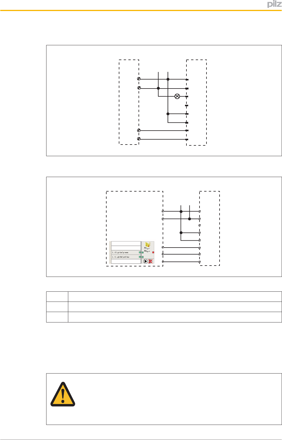
PSENcs5.1p
OperatingManualPSENcs5.1p
1003418EN01 18
PNOZs3
PSENcode
0 V
24 V
A1
A2
Y32
n.c.
S11
S21
12
22
2
7
8
6
1
3
4
5
PNOZ s3
A1
A2
S22
S12
PNOZmulti
I2
I0
I1
grün
grau
gelb
PNOZmulti PSENcode
A1
A2
Y32
n.c.
S11
S21
12
22
2
7
8
6
1
3
4
5
A1
A2
0 V
24 V
Legend:
I0 InputOSSD
I1 InputOSSD
I2 Signalinput
Teachingintheactuator
AnyPilzactuatorPSENcs5.1)isdetectedassoonasitisbroughtintotheresponserange.
Installation
CAUTION!
Theunit'spropertiesmaybeaffectedifinstalledinanenvironmentcontain
ingelectricallyormagneticallyconductivematerial.Pleasechecktheoper
atingdistancesandtheassuredreleasedistance.
PSENcs5.1p
OperatingManualPSENcs5.1p
1003418EN01 19
}Thesafetyswitchandactuatorshouldbeinstalledoppositeeachotherinparallel.
Makesurethattheactuatorisalignedtothemarkingonthesensorthatguaranteesthe
operatingdistancerequiredbytheplantdesign(seeOperatingdistances[ 10]).
}SafetyswitchesandactuatorsshouldonlybesecuredusingM4screwswithaflathead
(e.g.M4cheeseheadorpanheadscrews).
}Torquesetting:Notethestatedmax.torqueintheTechnicaldetails[ 24].
}Thedistancebetweentwosafetyswitchesmustbemaintained(seeTechnical
Details[ 24]).
}Ifusingangledconnectorplugs,notethedefinedangleofthecablerouting.
}WheninstallingmakesureyoucomplywiththerequirementsofENISO14119.
}Makesurethatthesafetyswitchandactuatorcannotbeusedasanendstop.
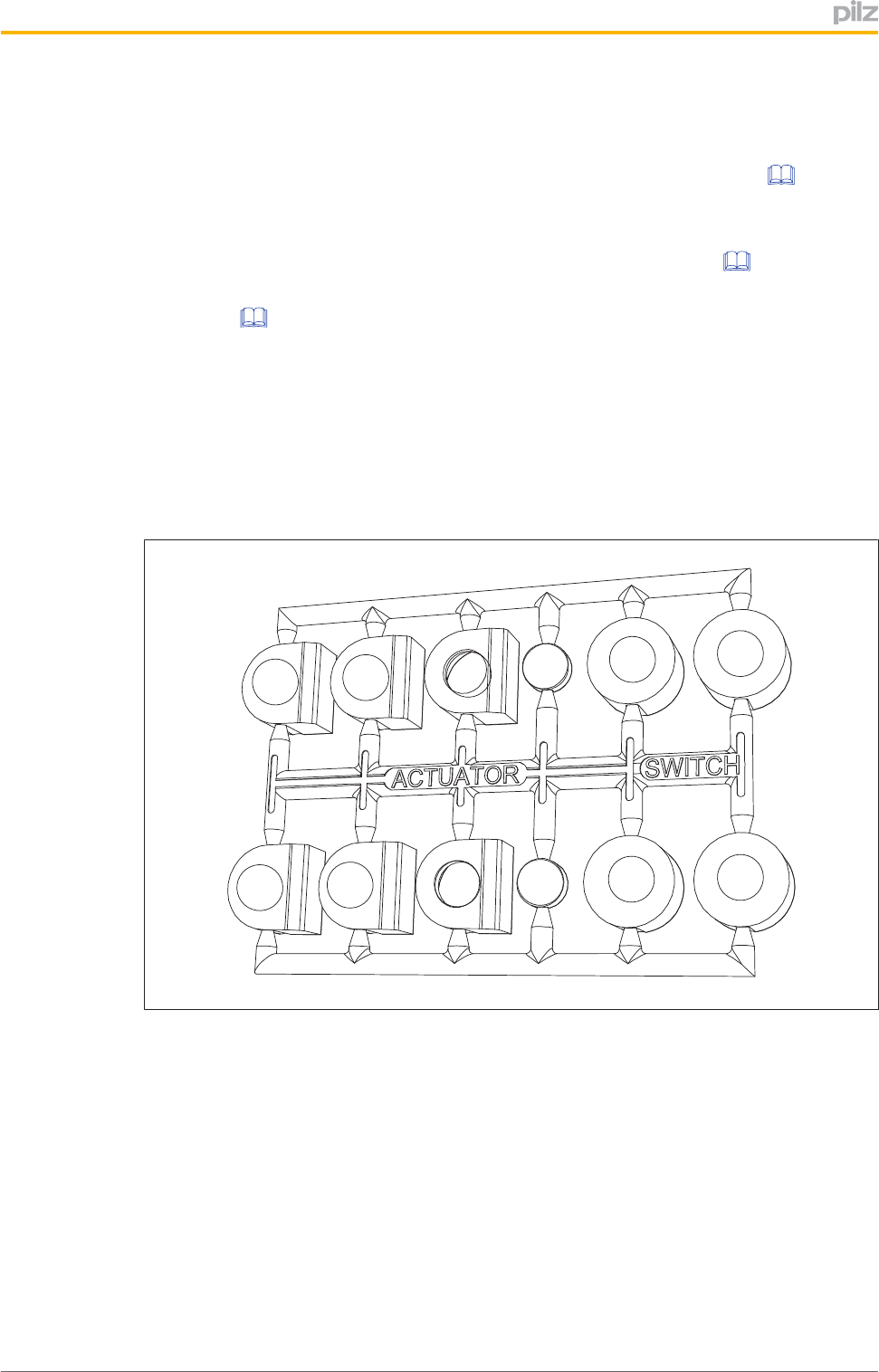
}Theactuatorshouldbeprotectedfromunauthorisedremovalandfromcontamination.
Closethemountingholesusingthesealsprovided(seediagrams).Theuseofseals
shouldberegardedasequivalenttousingpermanentfasteningsinaccordancewith
Clause7.2cofENISO14119.
[4]
[4]
[3]
[2]
[1]
[1]
[4]
[4]
[3]
[2]
[1]
[1]
Fig.:Seals
[1]:4sealsforactuators
[2]:Unusedseals
[3]:2sealsforactuators
[4]:2sealsforswitches,2sealsunused
PSENcs5.1p
OperatingManualPSENcs5.1p
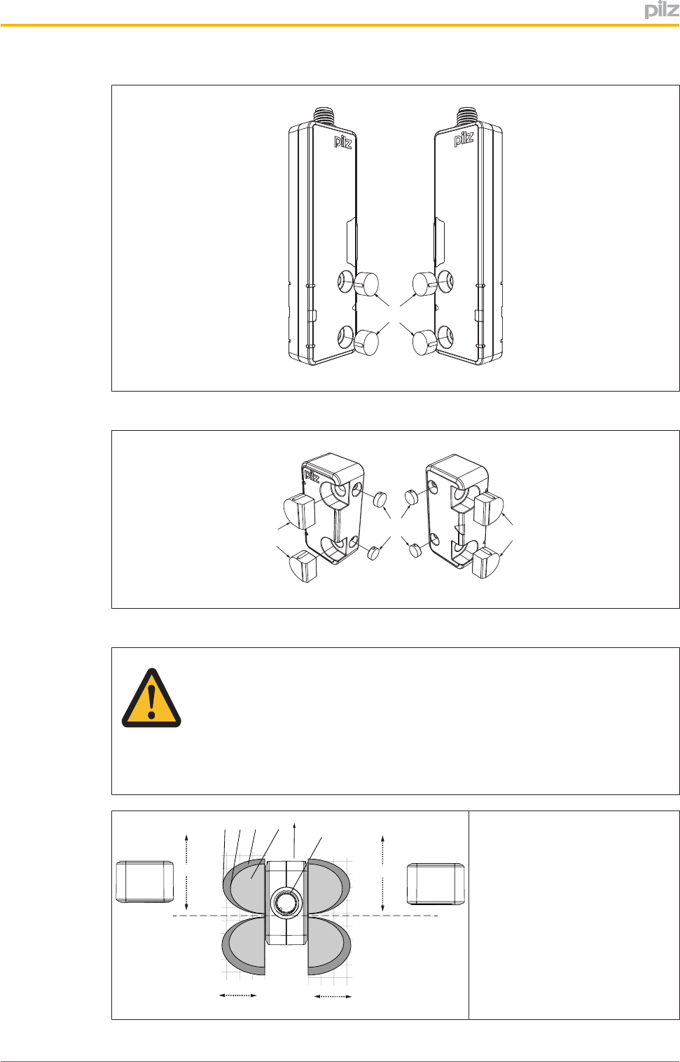
1003418EN01 20
[4]
Fig.:Applyingthescrewcover[4]ontheswitch
[1] [1]
[3]
Fig.:Applyingthescrewcovers[1]and[3]ontheactuator
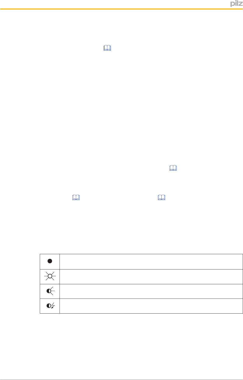
CAUTION!
Malfunctionduetomissinggateendstoponsemicirclemarking
Ifyouusethesemicirclemarkingonasafetygate,makesurethatagate
endstopisused.Theactuatormaynotbemovedbeyondthelimitofthere
sponserange(seediagram).
[7]
[8]
[1][2]
[3] [6]
[4]
[4]
[5]
8
4
0
-4
-8
-12
-16
-20
-24
-28
12 8 4 0
[9]
8
4
0
-4
-8
-12
-16
-20
-24
-28
[5]
1284
0
[4]
[4]
[1]:Hysteresis
[2]:Typicaloperatingdistance
SO
[3]:TypicalreleasedistanceSr
[4]:Offsetinmm
[5]:Operatingdistanceinmm
[6]:Responserange
[7]:Connectoronthesensor
[8]Limitofresponserange,pos
itionofgateendstop
[9]:StatusofLED
PSENcs5.1p
OperatingManualPSENcs5.1p
1003418EN01 21
Procedure:
1. Drillholes(forM4screws)inthemountingsurfacetosecuretheactuatorandsensor
(seeDimensionsinmm[ 23]).
2. Useascrewtofixthesensortothemountingsurface.
Makesurethatthesensormarkingthatisbeusedforoperationcanbeoperatedusing
theactuatorfromtherightside.
3. Donotfullytightenthesecondscrewonthesafetyswitch.
4. Useascrewtofixtheactuatortothemountingsurface.
Makesurethattheactuatorwiththemarking(triangle)pointstowardsthemarkingon
thesensor.
5. Donotfullytightenthesecondscrewontheactuator.
6. Alignthesafetyswitchandtightenthescrews.
7. Aligntheactuatorandtightenthescrews.
Forsimplerinstallation,themountingbracketswithordernumber532110canbeused.
Adjustment
}Thestatedoperatingdistances(seeTechnicaldetails[ 24])onlyapplywhenthe
safetyswitchandactuatorareinstalledfacingeachotherinparallel.Operatingdis
tancesmaydeviateifotherarrangementsareused.
}Notethemaximumpermittedlateralandverticaloffset(seeOperating
distances[ 10]andLateralandverticaloffset[ 13]).
Operation
Checkthefunctionofthesafetyswitchbeforecommissioning.
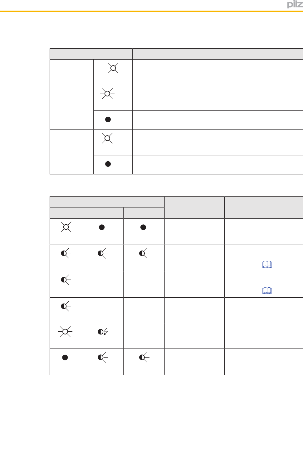
Statusindicators:
Legend:
LEDoff
LEDon
LEDflashes(500mson,500msoff)
LEDflashesquickly(50mson,950msoff)
PSENcs5.1p
OperatingManualPSENcs5.1p
1003418EN01 22
Normalmode
LEDstatus Switchstatus
Device
Green
Readyforoperation
SafetyGate
yel
low
Actuatoriswithintheresponserange
Off
Actuatorisoutsidetheresponserange
Input
yel
low
Bothsafetyinputsarehigh
Off
Bothsafetyinputsarelow
Errordisplay
LEDstatus
Switchstatus Remedy/measureDevice Safetygate Input
red
Off
Off
Internalerroron
switch
Changetheswitch
red
yellow
yellow
Supplyvoltageis
outsidethetoler
ancerange
Ensurethevoltagesupply
correspondstotheTech
nicaldetails[ 24].
yellow
Displaynot
definitive
Displaynot
definitive
Supplyvoltageisat
thelimitofthetoler
ancerange
Ensurethevoltagesupply
correspondstotheTech
nicaldetails[ 24].
red
Displayof
laststatus
Displayof
laststatus
Outputsinfaultcon
dition
Checktheoutputsand
switchthevoltageoffand
thenonagain.
green
yellow
Displaynot
definitive
Wrongactuator UsetheactuatorPSEN
cs5.1.
Off
yellow
yellow
Switchdoesn'tstart Changetheswitch.
PSENcs5.1p
OperatingManualPSENcs5.1p
1003418EN01 23
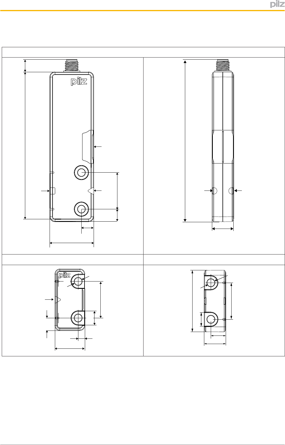
Dimensionsinmm
Safetyswitch
[1] [2]
90
26,4
7,5
DEVICE
SAFETY GATE
INPUT
22
7,4
7,6
[3]
[4] [4]
97,6
13
Actuator
18
22
[2]
7,5
4,5
4
8,3
8,3
37
22
13
9
4,5
5
Legend:
[1]Squaremarking
[2]Trianglemarking
[3]LEDs
[4]Semicirclemarking

PSENcs5.1p
OperatingManualPSENcs5.1p
1003418EN01 24
Technicaldetails
General
Approvals CE,EAC(Eurasian),ECOLAB,FCC,IC,TÜV,UL/
cUL
Sensor'smodeofoperation Transponder
CodificationinaccordancewithISO14119 Low
BuildingclassinaccordancewithISO14119 4
ClassificationtoEN6094753 PDDB
Electricaldata
Supplyvoltage
Voltage 24,0V
Kind DC
Voltagetolerance 20%/+20%
Outputofexternalpowersupply(DC) 1,0W
Max.switchingfrequency 3Hz
Max.cablecapacitanceatthesafetyoutputs
Noload,PNOZwithrelaycontacts 40nF
PNOZmulti,PNOZelog,PSS 40nF
Max.inrushcurrentimpulse
Currentpulse,A1 0,50A
Noloadcurrent 25mA
Inputs
Number 2
Voltageatinputs 24VDC
Inputcurrentrange 1,63,0mA
Semiconductoroutputs
OSSDsafetyoutputs 2
Signaloutputs 1
Switchingcurrentperoutput 100mA
Breakingcapacityperoutput 2,4W
Residualcurrentatoutputs 400µA
VoltagedropatOSSDs 1,0V
Conditionalratedshortcircuitcurrent 100A
Lowestoperatingcurrent 0mA
UtilisationcategoryinaccordancewithEN609471 DC12
Times
Testpulseduration,safetyoutputs 150µs
Switchondelay
afterUBisapplied 1,0s
Inputstyp. 1ms
Inputsmax. 3ms
Actuatortyp. 30ms
Actuatormax. 50ms

PSENcs5.1p
OperatingManualPSENcs5.1p
1003418EN01 25
Times
Delayondeenergisation
Inputstyp. 2ms
Inputsmax. 4ms
Actuatortyp. 30ms
Actuatormax. 40ms
RisktimeinaccordancewithEN6094753 150ms
Supplyinterruptionbeforedeenergisationintheinput
circuit 450,0µs
Supplyinterruptionbeforedeenergisation 20ms
Simultaneity,channel1and2 ∞
Environmentaldata
Ambienttemperature
Inaccordancewiththestandard EN60068214
Temperaturerange 2570°C
Storagetemperature
Inaccordancewiththestandard EN6006821/2
Temperaturerange 4085°C
Climaticsuitability
Inaccordancewiththestandard EN60068230
Humidity 93%r.h.at40°C
EMC EN6094753
Vibration
Inaccordancewiththestandard EN6094752
Frequency 10,055,0Hz
Amplitude 1,00mm
Shockstress
Inaccordancewiththestandard EN6094752
Acceleration 30g
Duration 11ms
Airgapcreepage
Overvoltagecategory III
Pollutiondegree 3
Ratedinsulationvoltage 75V
Ratedimpulsewithstandvoltage 1,00kV
Protectiontype
Housing IP66,IP67
Mechanicaldata
Actuator1 PSENcs5.1
Operatingdistances
Repetitionaccuracyswitchingdistances 3%
Changeofoperatingdistancewithtemperature
changes +0,02mm/°C

PSENcs5.1p
OperatingManualPSENcs5.1p
1003418EN01 26
Mechanicaldata
Operatingdistanceswhentheactuatorapproaches
squaremarking
AssuredoperatingdistanceSao 8mm
AssuredreleasedistanceSar 20mm
TypicaloperatingdistanceSo 11mm
TypicalreleasedistanceSr 14mm
Typicalhysteresis 2mm
Operatingdistanceswhentheactuatorapproaches
trianglemarking
AssuredoperatingdistanceSao 4mm
AssuredreleasedistanceSar 12mm
TypicaloperatingdistanceSo 5mm
TypicalreleasedistanceSr 8mm
Typicalhysteresis 2mm
Operatingdistanceswhentheactuatorapproaches
semicirclemarking
AssuredoperatingdistanceSao 6mm
AssuredreleasedistanceSar 19mm
TypicaloperatingdistanceSo 9mm
TypicalreleasedistanceSr 11mm
Typicalhysteresis 2mm
Min.distancebetweensafetyswitches 250mm
SensorflushinstallationinaccordancewithEN
6094752 Yes,followinstallationguidelines
Connectiontype M8,8pinmaleconnector
Material Lexan9945,PA+GF,PBT
Fixingscrewstorquesettings 1,00Nm
Dimensions
Height 26,4mm
Width 97,6mm
Depth 13,0mm
Actuatordimensions
Height 18,0mm
Width 37,0mm
Depth 13,0mm
Weightofsafetyswitch 48g
Weightofactuator 10g
Weight 58g
Wherestandardsareundated,the201409latesteditionsshallapply.
PSENcs5.1p
OperatingManualPSENcs5.1p
1003418EN01 27
Safetycharacteristicdata
Operating
mode
ENISO
138491:
2008
PL
ENISO
138491:
2008
Category
EN62061
SILCL
EN62061
PFHD[1/h]
IEC61511
SIL
IEC61511
PFD
ENISO
138491:
2008
TM[year]
2ch.OSSD PLe Cat.4 SILCL3 9,56E10 –8,51E06 20
Alltheunitsusedwithinasafetyfunctionmustbeconsideredwhencalculatingthesafety
characteristicdata.
INFORMATION
Asafetyfunction'sSIL/PLvaluesarenotidenticaltotheSIL/PLvaluesof
theunitsthatareusedandmaybedifferent.Werecommendthatyouuse
thePAScalsoftwaretooltocalculatethesafetyfunction'sSIL/PLvalues.
Supplementarydata
Radioapproval
USA/Canada
FCC ID: VT8-
IC: 7482A-
FCC/IC-Requirements:
This product complies with Part 15 of the FCC Rules and with Industry Canada licence-exempt RSS standards.
Operation is subject to the following two conditions:
1) this product may not cause harmful interference, and
2) this product must accept any interference received, including interference that may cause undesired operation.
Changes or modifications made to this product not expressly approved by Pilz may void the FCC authorization to operate this equipment.
NOTE: This equipment has been tested and found to comply with the limits for a Class A digital device, pursuant to Part 15 of the FCC Rules.
These limits are designed to provide reasonable protection against harmful interference when the equipment is operated in a commercial
environment. This equipment generates, uses, and can radiate radio frequency energy and, if not installed and used in accordance with the
instruction manual, may cause harmful interference to radio communications. Operation of this equipment in a residential area is likely to cause
harmful interference in which case the user will be required to correct the interference at his own expense.
Le présent produit est conforme aux CNR d'Industrie Canada applicables aux appareils radio
exempts de licence. L'exploitation est autorisée aux deux conditions suivantes:
(1) le produit ne doit pas produire de brouillage, et
(2) l'utilisateur de le produit doit accepter tout brouillage radioélectrique subi, même si le brouillage est susceptible d'en compromettre le
fonctionnement.
PSENCS5
PSENCS5
Orderreference
System
Producttype Features Connectiontype Orderno.
PSENcs5.1p/PSENcs5.11unit Safetygatesystem,
coded
8pinM8connector 542000
PSENcs5.1p1switch Safetyswitch,coded 8pinM8connector 542050
PSENcs5.11actuator Actuator,coded 542080

PSENcs5.1p
OperatingManualPSENcs5.1p
1003418EN01 28
Accessories
Producttype Features Orderno.
PSENWinkel/bracket Mountingbracket 532110
ECdeclarationofconformity
Thisproduct/theseproductsmeettherequirementsofthedirective2006/42/ECforma
chineryoftheEuropeanParliamentandoftheCouncil.ThecompleteECDeclarationof
ConformityisavailableontheInternetatwww.pilz.com/downloads.
Representative:NorbertFröhlich,PilzGmbH&Co.KG,FelixWankelStr.2,73760Ost
fildern,Germany
The Best of
German
En gineering
Partner of:
Support
Technical support is available from Pilz round the clock.
Americas
Brazil
+55 11 97569-2804
Canada
+1 888-315-PILZ (315-7459)
Mexico
+52 55 5572 1300
USA (toll-free)
+1 877-PILZUSA (745-9872)
Asia
China
+86 21 60880878-216
Japan
+81 45 471-2281
South Korea
+82 31 450 0680
Australia
+61 3 95446300
Europe
Austria
+43 1 7986263-0
Belgium, Luxembourg
+32 9 3217575
France
+33 3 88104000
Germany
+49 711 3409-444
Ireland
+353 21 4804983
Italy
+39 0362 1826711
Scandinavia
+45 74436332
Spain
+34 938497433
Switzerland
+41 62 88979-30
The Netherlands
+31 347 320477
Turkey
+90 216 5775552
United Kingdom
+44 1536 462203
You can reach our
international hotline on:
+49 711 3409-444
support@pilz.com
CMSE ®, InduraNET p ®, PAS4000 ®, PAScal ®, PASconfig ®, Pilz ®, PIT ®, PLID ®, PMCprimo ®, PMCprotego ®, PMCtendo ®, PMD ®, PMI ®, PNOZ ®, Primo ®, PSEN ®, PSS ®, PVIS ®, SafetyBUS p ®,
SafetyEYE ®, SafetyNET p ®, the spirit of safety ® are registered and protected trademarks of Pilz GmbH & Co. KG in some countries. We would point out that product features may vary
from the details stated in this document, depending on the status at the time of publication and the scope of the equipment. We accept no responsibility for the validity, accuracy
and entirety of the text and graphics presented in this information. Please contact our Technical Support if you have any questions.
Pilz develops environmentally-friendly products using
ecological materials and energy-saving technologies.
products and environmentally-friendly solutions.
Pilz GmbH & Co. KG
Felix-Wankel-Straße 2
73760 Ostfildern, Germany
Tel.: +49 711 3409-0
Fax: +49 711 3409-133
info@pilz.com
www.pilz.com
100XXXX-DE-0X
0-0-2-3-000, 2014-00 Printed in Germany
© Pilz GmbH & Co. KG, 2014
1003418EN01,201411PrintedinGermany
©PilzGmbH&Co.KG,2011
Backcover