Pilz and KG PSENML RFID Proximity switch User Manual PSEN ml b 2 1 2 2 Operat Man 1003895 EN xx
Pilz GmbH & Co. KG RFID Proximity switch PSEN ml b 2 1 2 2 Operat Man 1003895 EN xx
UserManual.wiki
>
Pilz and KG
>
PSENML User Manual
>
Users Manual PSEN ml b 2.1_570403_V2.0
Contents
1.
user manual
2.
Users Manual PSEN ml s 2.2_570411_V2.0
3.
Users Manual PSEN ml s 2.1_570409_V2.0
4.
Users Manual PSEN ml b 2.1_570403_V2.0
5.
Users Manual PSEN ml s 1.1_570407_V2.0
6.
Users Manual PSEN ml b 1.1_570401_V2.0
7.
Users Manual PSEN ml b 2.2_570405_V2.0
Users Manual PSEN ml b 2.1_570403_V2.0
Navigation menu
Upload a User Manual
Namespaces
Wiki Guide
HTML
PDF
Info
Views
User Manual
Discussion / Help
Navigation


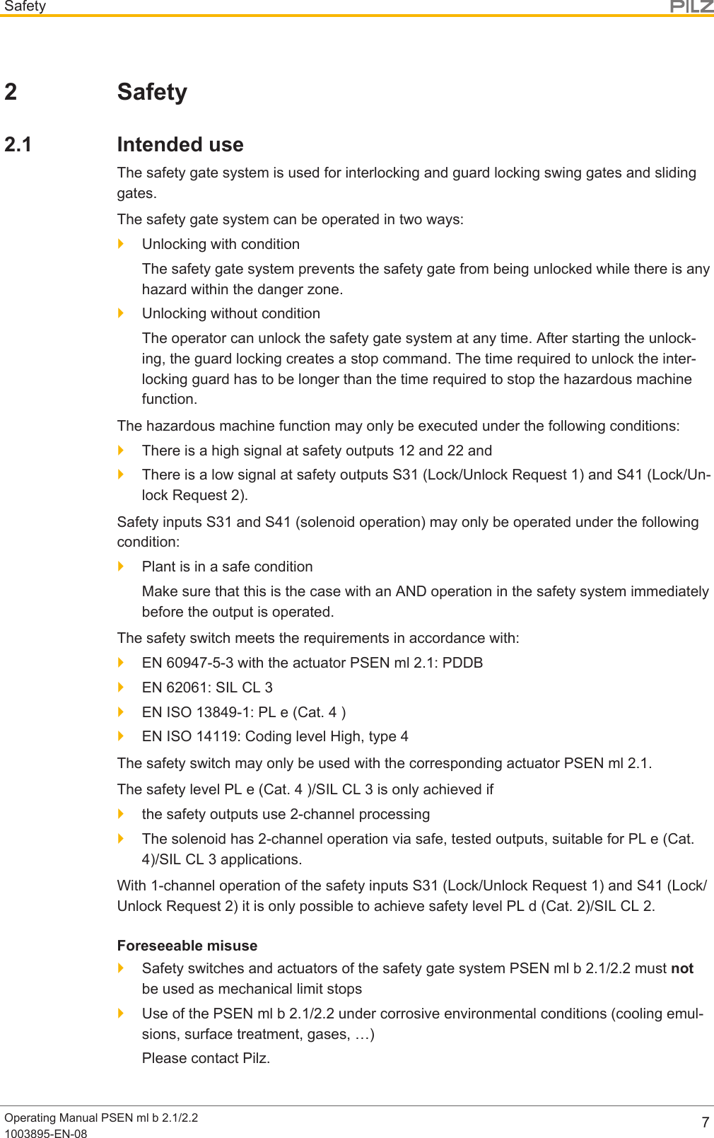
![SafetyOperating Manual PSEN ml b 2.1/2.21003895-EN-08 92.2.4 Warranty and liabilityAll claims to warranty and liability will be rendered invalid if}The product was used contrary to the purpose for which it is intended,}Damage can be attributed to not having followed the guidelines in the manual,}Operating personnel are not suitably qualified,}Any type of modification has been made (e.g. exchanging components on the PCBboards, soldering work etc.).2.2.5 Disposal}In safety-related applications, please comply with the mission time TM in the safety-re-lated characteristic data.}When decommissioning, please comply with local regulations regarding the disposal ofelectronic devices (e.g. Electrical and Electronic Equipment Act).2.3 For your safetyWARNING!Loss of safety function due to substituting an actuator from the interlockingand guard locking systemSubstituting an actuator for an inappropriate actuator may lead to serious in-jury and death.– You should prevent the interlocking and guard locking system frombeing manipulated with an inappropriate actuator.– Keep the substitute actuator in a safe place and protect it from unau-thorised access.– If substitute actuators are used, these must be installed as describedunder Installation [ 29]– If the original actuators are replaced with substitute actuators, the ori-ginal actuators must be destroyed before disposal.}Do not remove the connector's protective cap until you are just about to connect theunit. This will prevent potential contamination.](https://usermanual.wiki/Pilz-and-KG/PSENML.Users-Manual-PSEN-ml-b-2-1-570403-V2-0/User-Guide-3840728-Page-9.png)
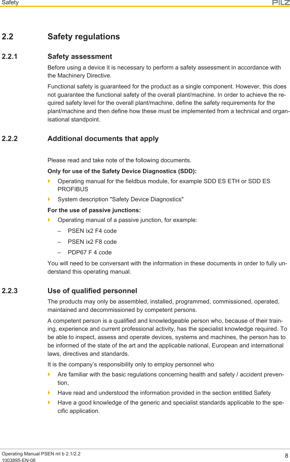
![OverviewOperating Manual PSEN ml b 2.1/2.21003895-EN-08 103 Overview3.1 Unit features}Safe guard locking for swing gates and sliding gates}Safe interlocking (position monitoring)}Transponder technology}2 safety outputs}Safety Device Diagnostics (SDD)– Safety Device Diagnostics can be used to poll sensor information, to perform ac-tions and to read configuration parameters– Manipulation protection in accordance with ISO 14119 (chap. 7.2.d) is possible byverifying the short name of the actuator through the controller via SDD communica-tion}Diagnostic input for Y1 for Safety Device Diagnostics (SDD)}Signal output/diagnostic output Y32 for Safety Device Diagnostics}Monitoring of shorts between the safety outputs}Guard locking element keeps the safety gate from being opened unintentionally}Auxiliary release for opening the safety gate}1 signal output}Suitable for left and right hinged safety gates}Pilz type of coding: Fully coded/uniquely coded}M12, 8-pin male connector}LEDs:– Supply voltage/fault– Status of actuator– Status of guard locking– Input lights up yellow (without function)}The bolt in the actuator can be rotated 90° in the actuator housing before the actuator isinstalled. As a result, the actuator can be installed vertically or horizontally.}The safety switch PSEN ml b 2.1/2.2 can be expanded using a stationary or externalescape release (see Order reference: Accessories [ 66]).The stationary escape release can be expanded by 25 mm max. two times.The external escape releases are available with push/pull cables between 1.5and4min length (grading 50cm).3.2 Scope of supply}Scope of supply PSEN ml b 2.1/2.2– Safety switch PSEN ml b 2.1/2.2– Actuator](https://usermanual.wiki/Pilz-and-KG/PSENML.Users-Manual-PSEN-ml-b-2-1-570403-V2-0/User-Guide-3840728-Page-10.png)
![Function descriptionOperating Manual PSEN ml b 2.1/2.21003895-EN-08 134.2.2 Activation without specification of direction}The guard locking changes its state when the time between the rising edges from S31and S41<20ms.4.3 Safety Device DiagnosticsSafety Device Diagnostics is an option that can be selected independently of the safety-re-lated wiring.When using the Safety Device Diagnostics, up to 16 sensors can be connected as a sub-scriber to a fieldbus module.The communication of the sensors with the fieldbus module is automatically built up againwith each new supply of the supply voltage. As a result, a sensor can be exchanged, e.g.when servicing, without the need for special measures.An exchange can be detected via the fieldbus module e.g. through the serial number.}With Safety Device Diagnostics there are the following diagnostic options for the field-bus module:– Poll information of the sensors (examples: what sensor in the series has switched,at what point could there be an open circuit in the series connection)– Read configuration parameters of the sensor (examples: Number of teach-in pro-cesses remaining, serial number of the switch)– Perform actions (example: poll updated actuator name)– Selectively activate or deactivate guard locking of individual PSEN ml within aseries connectionThe results of the sensor diagnostics can be checked already during the installation phasevia the display in the fieldbus module, without the need to connect the fieldbus module tothe network.}With Safety Device Diagnostics there are the following diagnostic options for the field-bus module for simple wiring:– Information is passed on via the fieldbus module directly to the network– Mappings of the signal outputs to the sensor are automated by the SDD.This prevents wiring errors and an expansion or reduction of the sensors is possiblewithout the need to change existing wiring.– Wiring in accordance with IP20: Rapid installation in the control cabined is enabled.Further information on Safety Device Diagnostics can be found in Additional documentsthat apply [ 8].}Series connection of diagnostics with Safety Device Diagnostics](https://usermanual.wiki/Pilz-and-KG/PSENML.Users-Manual-PSEN-ml-b-2-1-570403-V2-0/User-Guide-3840728-Page-13.png)
![Function descriptionOperating Manual PSEN ml b 2.1/2.21003895-EN-08 15Timing diagrams[7]S31 + S41Y3212 + 22[1] [4][5][8][t1] [t1][t2][6][t2]Y1[2] [3]SDD command guard lockingGuard lockingActuatorFig.: Active use of Safety Device DiagnosticsLegend[1] Gate is open[2] Gate is closed[3] Guard locking is activated by the safety control system[4] Guard locking is activated[5] Execution of the hazardous machine function is permitted[6] Outputs will be deactivated[7] Guard locking will be deactivated[8] Gate is open[t1] Processing time of guard locking signal = 100 ms[t2] Time window for changing guard locking status](https://usermanual.wiki/Pilz-and-KG/PSENML.Users-Manual-PSEN-ml-b-2-1-570403-V2-0/User-Guide-3840728-Page-15.png)
![Function descriptionOperating Manual PSEN ml b 2.1/2.21003895-EN-08 16S31 + S41Y3212 + 22[1][4][5] [6] [8][7][t1] [t1][t2][t2]Y1[2] [3]Guard lockingActuatorFig.: Passive use of the Safety Device DiagnosticsLegend[1] Gate is open[2] Gate is closed[3] Guard locking is activated[4] Execution of the hazardous machine function is permitted[5] Outputs will be deactivated[6] Guard locking will be deactivated[7] Gate is open[t1] Processing time of guard locking signal = 100 ms[t2] Time window for changing guard locking status](https://usermanual.wiki/Pilz-and-KG/PSENML.Users-Manual-PSEN-ml-b-2-1-570403-V2-0/User-Guide-3840728-Page-16.png)
![Function descriptionOperating Manual PSEN ml b 2.1/2.21003895-EN-08 18INFORMATIONIf guard locking is deactivated using the auxiliary release, there is a low sig-nal at safety outputs 12 and 22. An error code will be issued (see underOperation [ 49]) and the safety switch switches to a fault condition.[1][2]Legend[1] Auxiliary release screw Torx T10[2] Security screw Torx T10, sealed with varnish when deliveredMode of operation:1. Remove the security screw [2] using a Torx T10 screwdriver.2. Rotate the auxiliary release screw [1] half a turn anti-clockwise using a Torx T10 screw-driver. The guard locking pin is displaced and the bolt is released.The safety gate to the danger zone can be opened.](https://usermanual.wiki/Pilz-and-KG/PSENML.Users-Manual-PSEN-ml-b-2-1-570403-V2-0/User-Guide-3840728-Page-18.png)
![Function descriptionOperating Manual PSEN ml b 2.1/2.21003895-EN-08 194.6.1 RecommissioningRecommission PSEN ml b 2.1/2.21. Rotate the auxiliary release screw [1] (see Figure [ 18]) half a turn clockwise using aTorx T10 screwdriver.2. Re-insert the security screw [2] (see Figure [ 18]) using a Torx T10 screwdriver.3. Seal the security screw with varnish.4. Switch the voltage off and then on again.5. Carry out a function test on the safety switch and actuator. The safety function may onlybe checked by qualified personnel.INFORMATIONIf the auxiliary release screw is not turned back correctly after use, thePSEN ml b 2.1/2.2 switches to a fault condition.4.7 Prevent restartTo prevent the machine restarting (unintentionally) while there is someone inside thedanger zone, a padlock can be attached via the through hole on the actuator (see diagram).As a result the actuator cannot engage with the safety switch, guard locking is not activatedand the machine is prevented from starting.[1][2][3]Legend[1] Through hole on the actuator for attaching a padlock[2] Padlock[3] ActuatorIf the actuator is to blocked using several locks in parallel, a multiple lock can be used (e.g.Brady – Lockout device, article no.852439).](https://usermanual.wiki/Pilz-and-KG/PSENML.Users-Manual-PSEN-ml-b-2-1-570403-V2-0/User-Guide-3840728-Page-19.png)
![Function descriptionOperating Manual PSEN ml b 2.1/2.21003895-EN-08 204.8 Escape releaseDistinction between escape release and emergency release}The emergency release enables the manual release of the guard locking without aidsfrom outside the hazardous area.}The emergency release enables the manual release of the guard locking without aidsfrom within the hazardous area and it corresponds to an escape release in accordancewith ENISO14119.If the escape release accessory (stationary or external) is installed within the hazardousarea, the accessory can be used as an escape release in accordance with ENISO14119.If the escape release accessory (stationary or external) is installed outside the hazardousarea, the accessory can be used as an escape release in accordance with ENISO14119.[1][2][3][4][5]Legend[1] Escape release stationary[2] Escape release externally[3] Tension pressure cables in lengths of 1.50m to 4m[4] Button of the escape release pin[5] Escape release pinINFORMATIONIf guard locking is deactivated using the auxiliary release, there is a low sig-nal at safety outputs 12 and 22. An error code will be issued (see underOperation [ 49]) and the safety switch switches to a fault condition.](https://usermanual.wiki/Pilz-and-KG/PSENML.Users-Manual-PSEN-ml-b-2-1-570403-V2-0/User-Guide-3840728-Page-20.png)
![Function descriptionOperating Manual PSEN ml b 2.1/2.21003895-EN-08 21Mode of operationIf in the hazardous area the button of the escape release pin [4] is pressed towards thesafety gate, the escape release impacts directly on the auxiliary release of the safety switchand the auxiliary release unlocks the safety gate. The safety gate can be opened immedi-ately, enabling the operator to leave the danger zone.There is a low signal at safety outputs 12 and 22 if the escape release was operated.Scope}Scope of supply stationary escape release– 1 escape release stationary– 1 adapter disk– 2 screws for adapter disk– 4 screws for installation on the adapter disk}Scope of supply external escape release– 1 escape release external with installed push/pull cables (see Order reference:Accessories [ 66])– 1 adapter disk– 2 screws for adapter disk– 4 screws for installation on the adapter disk4.8.1 Recommissioning1. Pull back the button of the escape release pin.2. Switch the voltage off and then on again.3. Carry out a function test using the escape release. The safety function may only bechecked by qualified personnel.](https://usermanual.wiki/Pilz-and-KG/PSENML.Users-Manual-PSEN-ml-b-2-1-570403-V2-0/User-Guide-3840728-Page-21.png)
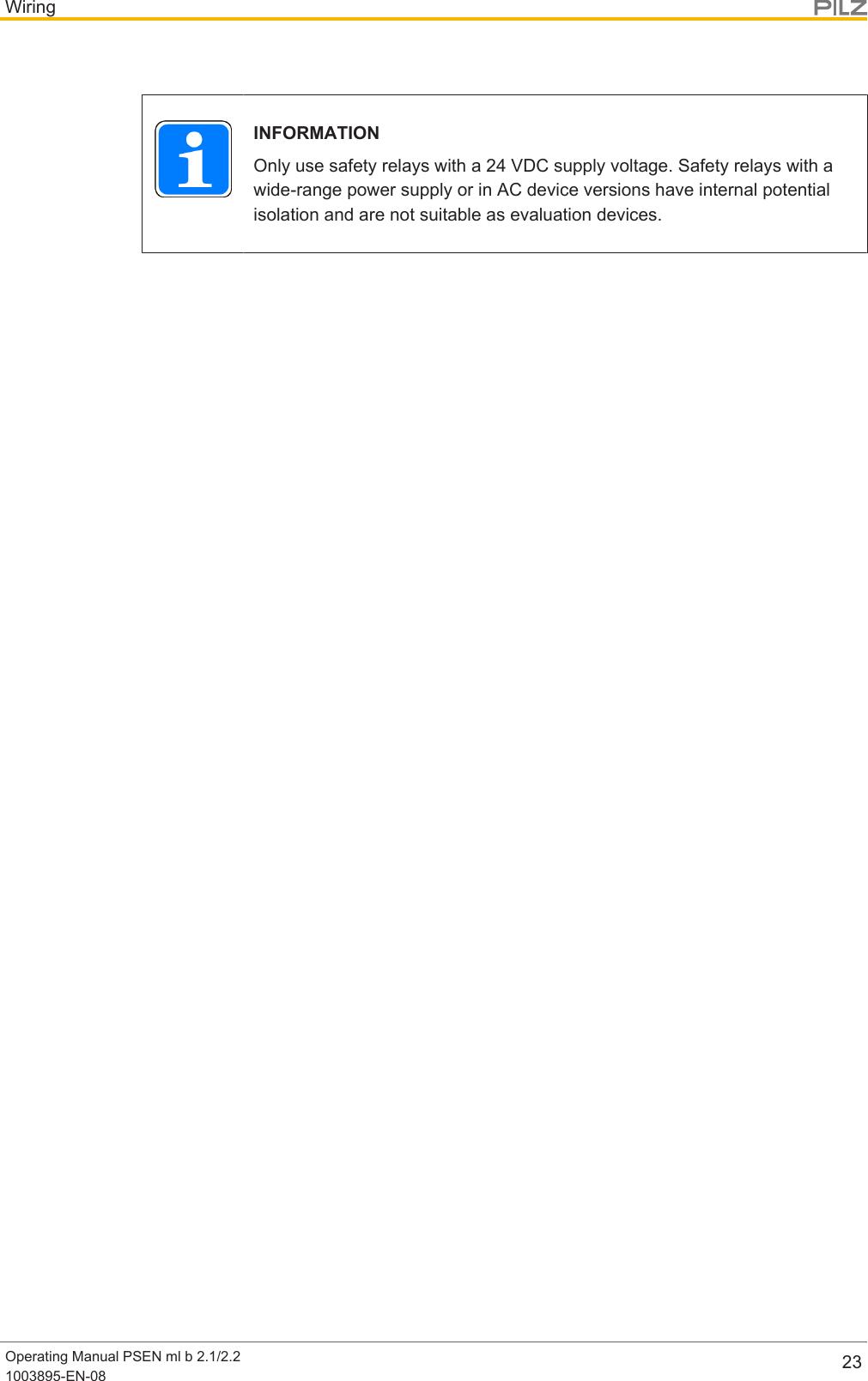
![WiringOperating Manual PSEN ml b 2.1/2.21003895-EN-08 225 Wiring5.1 Important information}Hand-tighten the connector.}Information given in the Technical details [ 60] must be followed.5.2 Pin assignment, connector and cable8-pin M12 connectorPIN Function Terminal designationCable colour (Pilzcable)1 Operation of solenoid toopen and close guard lock-ing (channel 2)S41 white2 +24 V UB A1 Brown3 Safety output channel 1 12 Green4 Safety output channel 2 22 Yellow5 Signal output/diagnosticoutputY32 grey6 Operation of solenoid toopen and close guard lock-ing (channel 1)S31 Pink7 0 V UB A2 Blue8 Diagnostics input Y1 RedNOTICEThe colour marking for the connection lead only applies for the cable thatPilz supplies as an accessory5.3 EMC requirements}Ensure the wiring and EMC requirements of EN 60204-1 are met.}UL requirement: The supply voltage to the safety switch must be protected with a quick-acting fuse (see Technical details [ 60]).}The inputs and outputs of the safety switch must have a protective separation tovoltages over 60 V AC.}The power supply must meet the regulations for extra low voltages with protective sep-aration (SELV, PELV) in accordance with EN60204-1.](https://usermanual.wiki/Pilz-and-KG/PSENML.Users-Manual-PSEN-ml-b-2-1-570403-V2-0/User-Guide-3840728-Page-22.png)
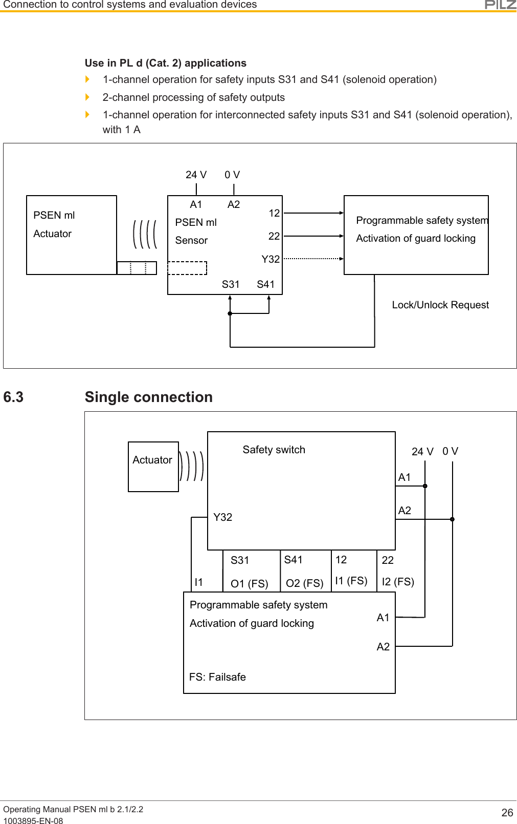
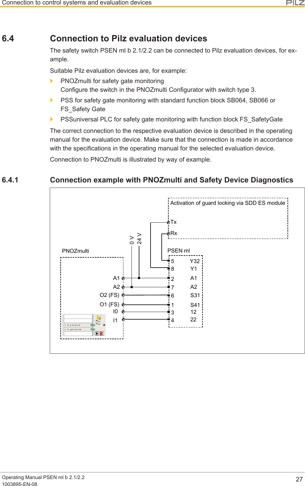
![Connection to control systems and evaluation devicesOperating Manual PSEN ml b 2.1/2.21003895-EN-08 246 Connection to control systems and evaluationdevices6.1 Important informationMake sure that the selected evaluation device has the following properties:}2-channel with feasibility monitoringBoth OSSDs must change switch state synchronously. In particular, the evaluationdevice must monitor that the state of both OSSDs was "Gate unlocked" before both re-turn to the "Gate locked" state and vice-versa.}OSSD signals are evaluated through 2 channels}The state of the OSSDs must be tested before and after safety inputs S31 and S41 areactivated (solenoid operation) (see Timing diagram [ 15])WARNING!Potential loss of safety function due to failure to test for a safe conditionDepending on the application, serious injury or death may result.– Use an evaluation device/safety system to test whether the plant is ina safe condition.– Do not operate the solenoid of the PSEN ml b 2.1/2.2 via S31/S41unless the plant is in a safe condition.}The use of Safety Device Diagnostics is described in the System Description "SafetyDevice Diagnostics".6.2 Minimum requirements for activation of guard lockingUse in PL e (Cat. 4) applications}Safety inputs S31 and S41 (solenoid operation) have 2-channel operation via safe out-puts, which are suitable for PL e (Cat. 4) applications}2-channel operation for safety inputs S31 and S41 (solenoid operation), each with 0.5A}2-channel processing of safety outputs}Monitoring of shorts across signal cables through activation of guard locking](https://usermanual.wiki/Pilz-and-KG/PSENML.Users-Manual-PSEN-ml-b-2-1-570403-V2-0/User-Guide-3840728-Page-24.png)
![Connection to control systems and evaluation devicesOperating Manual PSEN ml b 2.1/2.21003895-EN-08 25PSEN mlActuatorA1 A222Y32S31 S4112PSEN mlSensor24 V 0 VLock/Unlock Request 2Lock/Unlock Request 1Programmable safety systemActivation of guard lockingUse in PL d (Cat. 3) applications}2-channel operation for safety inputs S31 and S41 (solenoid operation) via relay out-puts}2-channel operation for safety inputs S31 and S41 (solenoid operation), each with 0.5A}2-channel processing of safety outputs}Exclusion of shorts across signal cables through appropriate measures (e.g. protectedcable layout, see EN ISO 13849-2)PSEN mlActuatorA1 A222Y32S31 S4112PSEN mlSensor24 V 0 VLock/Unlock Request 2Lock/Unlock Request 124 V[1]Programmable safety systemActivation of guard lockingLegend[1] Protected cable layout](https://usermanual.wiki/Pilz-and-KG/PSENML.Users-Manual-PSEN-ml-b-2-1-570403-V2-0/User-Guide-3840728-Page-25.png)
![Teaching in the actuatorOperating Manual PSEN ml b 2.1/2.21003895-EN-08 287 Teaching in the actuator7.1 PSEN ml 2.1Teaching in the actuator for the first time:The first actuator to be detected by the safety switch (see Technical details [ 60]) istaught in automatically as soon as it is brought into the response range.To teach in a new actuator:}A maximum of 8 learning procedures are possible.1. The actuator that is to be taught in must be brought into the safety switch's responserange as the only transponder. As soon as the actuator is detected, the "Safety Gate"LED will flash yellow.2. After 20 s has elapsed, the "Safety Gate" LED turns to quick yellow flashes. Trigger asystem reset in the next 120 s by interrupting the power supply.3. When the supply voltage is switched back on, the learning procedure is complete andthe number of permitted additional learning procedures is reduced by 1.NOTICE– The actuator must not be removed during the learning procedure.– This actuator cannot be retaught on the same safety switch.7.2 PSEN ml 2.2The first actuator to be detected by the safety switch (see Technical details [ 60]) istaught in automatically as soon as it is brought into the response range.NOTICENo other actuator may be taught in once this actuator has been taught.](https://usermanual.wiki/Pilz-and-KG/PSENML.Users-Manual-PSEN-ml-b-2-1-570403-V2-0/User-Guide-3840728-Page-28.png)
![InstallationOperating Manual PSEN ml b 2.1/2.21003895-EN-08 298 Installation8.1 Important informationINFORMATIONRefer to the guidelines for designing guards and integrating interlocks withguard locking in ENISO14120.NOTICEInstall the safety switch and actuator so that the possibilities of defeat arereduced to a minimum (see guidelines for reducing the possibilities for de-feating interlocking devices in EN ISO 14119).NOTICEInstall safety switch and actuator so that it is not possible to reach throughwith hand or finger.}The safety switch and actuator should be installed opposite each other in parallel.}Make sure that the actuator makes complete contact with the mounting surface.}Make sure that the at least one of the auxiliary release/escape releases can be oper-ated after installation.}For a minimum screw depth of 6 mm, M5 screws with resistance class 8.8 should beused to attach the safety switch and actuator.}Torque setting: Please note the information provided under Technical details [ 60].}Use non-removable flat head locking screws to attach the safety switch and actuator(e.g. cheese-head or pan head screws) or rivets.}Use the same type of screw to attach the safety switch and actuator.}Prevent self-loosening of the fastening elements on the safety switch and actuator,– On the safety switch: through torque (see Technical details [ 60])– On the actuator: through torque (see Technical details [ 60]) and bonded screwretention}Make sure that the actuator does not present a risk.}The mounting surfaces for safety switches and actuators can have a max. unevennessof 0.5 mm.}Prevent the safety switch and actuator being exposed to heavy shock or vibration.}The fastening of safety switch and actuator has to be sufficiently stable to ensure theproper operation of the safety switch and the actuator.](https://usermanual.wiki/Pilz-and-KG/PSENML.Users-Manual-PSEN-ml-b-2-1-570403-V2-0/User-Guide-3840728-Page-29.png)
![InstallationOperating Manual PSEN ml b 2.1/2.21003895-EN-08 308.2 Tapped hole}To fix the safety switch at the three possible mounting positions, there are 3 drill holeson 3 sides.As a result, the safety switch can be installed on the frames of left and right hinged slid-ing gates and swing gates. If necessary use a Mounting plate [ 39] or Mountingbracket [ 38] (see Order reference: Accessories [ 66]).Different holding forces arise, based on the installation.–Fixing screws in parallel to actuator [ 32]:Holding forceFZh=7.500 N,Holding forceF1maxin accordance withENISO14119=15.000 N–Fixing screws side-on to actuator [ 33]:Holding forceFZh=5.000 N,Holding forceF1maxin accordance withENISO14119=10.000 NINFORMATIONPlease note that the stated holding forces only apply when installed withouta mounting bracket. The holding forces when installed with a mountingbracket can be found in the table "Technical details for mountingbracket [ 65]".The tapped holes must have a depth of at least 6 mm.Installation of safety switch Tapped holeFixing screws in parallel/side-on to actuator,no mounting plateTapped holes for four M5 screws on themounting surface.Fixing screws in parallel/side-on to actuator,with mounting plateTapped holes for two M8 screws on themounting surface, for attaching the mount-ing plate.](https://usermanual.wiki/Pilz-and-KG/PSENML.Users-Manual-PSEN-ml-b-2-1-570403-V2-0/User-Guide-3840728-Page-30.png)
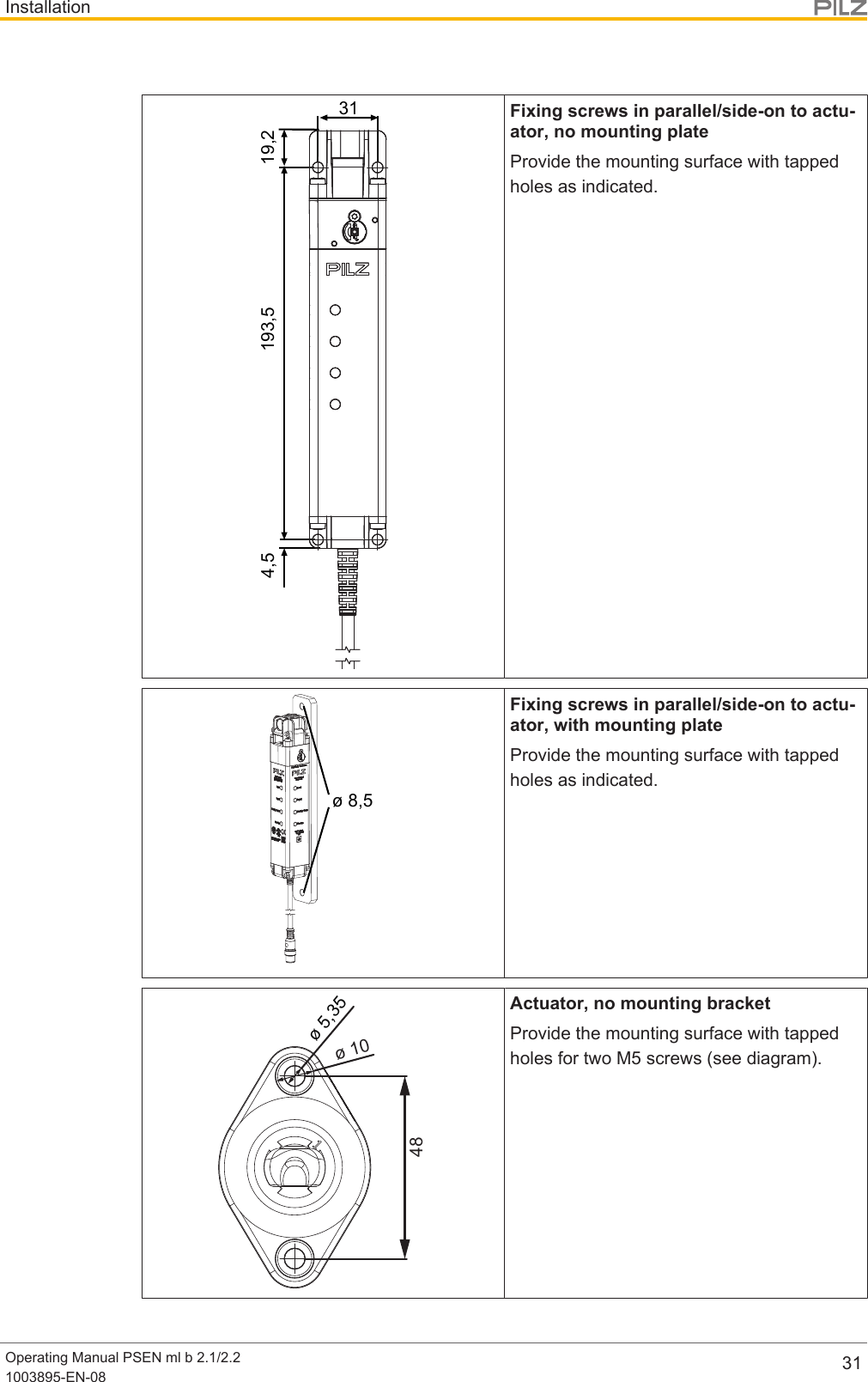
![InstallationOperating Manual PSEN ml b 2.1/2.21003895-EN-08 32ø 6,5Actuator, with mounting bracketProvide the mounting surface with tappedholes for two M6 screws (see Dimensions).(Diagram: order no. 570 492 as example)8.3 Install fixing screws in parallel to actuatorUse four M5 screws to attach the switch to the mounting surface.}Torque setting: Please note the information provided under Technical details [ 60].XY [3][3][1] [2]Fig.: Fixing screws of the safety switch in parallel to actuatorLegend[1] Safety switch[2] Actuator[3] Fixing screws of the safety switch in parallel to actuator](https://usermanual.wiki/Pilz-and-KG/PSENML.Users-Manual-PSEN-ml-b-2-1-570403-V2-0/User-Guide-3840728-Page-32.png)
![InstallationOperating Manual PSEN ml b 2.1/2.21003895-EN-08 338.4 Install fixing screws side-on to actuator[1][2][1] Front of safety switch[2] Actuator[1] [1][1] [1]Use four screws [1] to fix thesafety switch to the mount-ing surface.Fully tighten the four screws[1] on the safety switch.Torque setting: Please notethe information provided un-der Technicaldetails [ 60].](https://usermanual.wiki/Pilz-and-KG/PSENML.Users-Manual-PSEN-ml-b-2-1-570403-V2-0/User-Guide-3840728-Page-33.png)
![InstallationOperating Manual PSEN ml b 2.1/2.21003895-EN-08 348.5 Centre the bolt in the actuator housingThe bolt must be centred in the actuator housing in order to maintain the distances on set-tling gates.Centre the bolt in the actuator housing (see diagram).Bolt centred within the actuator hous-ingBolt not centred within the actuator housing8.6 Rotate the bolt in the actuator housing 90°The actuator can be installed vertically on a gate (see Figure [ 11]). To install the actu-ator horizontally, the bolt can be rotated 90° in the actuator housing prior to installation.1. On the housing skin [3] in the actuator housing, press down the spring plate [1] on bothsides of the bolt and keep the plate held down.2. Rotate the bolt in the housing skin by 90° in the required direction ([2]).[1][2][3]Legend[1] Spring plate in the housing skin[2] Bolt, can be rotated 90°[3] Housing skin](https://usermanual.wiki/Pilz-and-KG/PSENML.Users-Manual-PSEN-ml-b-2-1-570403-V2-0/User-Guide-3840728-Page-34.png)
![InstallationOperating Manual PSEN ml b 2.1/2.21003895-EN-08 353. Centre the bolt in the actuator housing [ 34].8.7 Installation on sliding gate[1][2]Legend[1] Safety switch, installed on gate frame[2] Actuator with mounting bracket (available as Accessory [ 66]), installed onsliding gate1. Install the safety switch with the fixing screws of the safety switch in parallel to theactuator [ 32] or side-on to actuator [ 33] on the gate frame.2. Use two M5 screws to fix the actuator to the gate.](https://usermanual.wiki/Pilz-and-KG/PSENML.Users-Manual-PSEN-ml-b-2-1-570403-V2-0/User-Guide-3840728-Page-35.png)
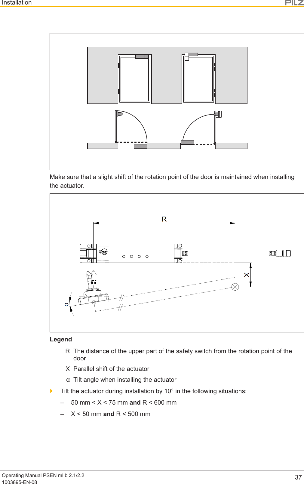
![InstallationOperating Manual PSEN ml b 2.1/2.21003895-EN-08 368.8 Installation on swing gate[1][2][2]Fig.: Swing gate with internal and external hingeLegend[1] Safety switch on gate frame[2] Actuator, installed on swing gate1. Install the safety switch with the fixing screws of the safety switch in parallel to theactuator [ 32] or side-on to actuator [ 33] on the gate frame.2. Use two M5 screws to fix the actuator to the gate.The actuator should engage smoothly into the safety switch.Install the safety switch horizontally at a swing gatePlease note:Depending on the installation boundary conditions, a larger gate radius may be required(see diagram).Please contact Pilz when smaller gate radiuses are required.](https://usermanual.wiki/Pilz-and-KG/PSENML.Users-Manual-PSEN-ml-b-2-1-570403-V2-0/User-Guide-3840728-Page-36.png)
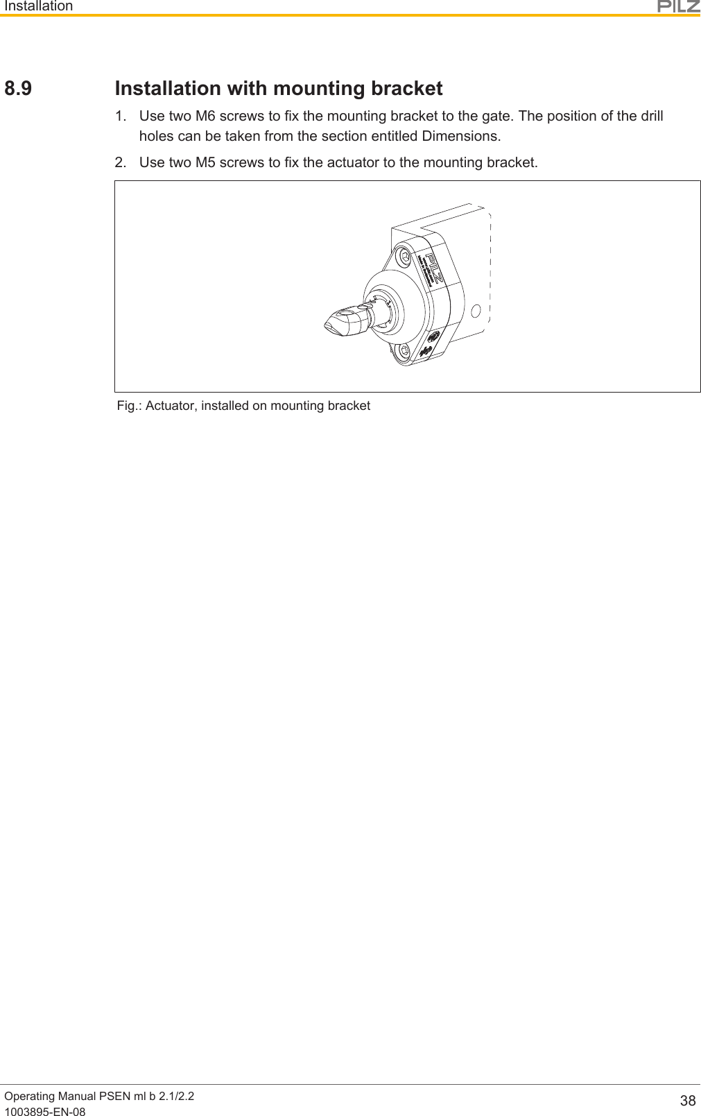
![InstallationOperating Manual PSEN ml b 2.1/2.21003895-EN-08 398.10 Installation with mounting plate1. Attach the mounting plate to the swing gate/sliding gate.2. Use four M5 screws to fix the safety switch [ 32] to the mounting plate.Fig.: Safety switch, installed on mounting plate8.11 Installing the escape release8.11.1 Important informationWARNING!Loss of safety function due to the incorrect installation of the escape re-lease!If the button of the escape release pin is accessible from the outside, theguard locking device can be released from the outside and the safety gatesopened, although the hazardous machine is switched on. Depending on the application, serious injury or death may result.The escape release should be installed so that it is only accessible from in-side the danger zone.}The button of the escape release pin must be impossible to reach from a position out-side the protected area.}Make sure that the escape release cannot be operated unintentionally.](https://usermanual.wiki/Pilz-and-KG/PSENML.Users-Manual-PSEN-ml-b-2-1-570403-V2-0/User-Guide-3840728-Page-39.png)
![InstallationOperating Manual PSEN ml b 2.1/2.21003895-EN-08 40}Prevent the effect of transverse forces on the escape release.}Secure the screw joints with a with a threadlocker.}Ensure that the button of the escape release pin is clearly visible and that is it notcovered.}Make sure that the min. bending radius of the push/pull cable of60mm is maintainedwhen using the external escape release.}Make sure that the button of the escape release pin does not present a risk.}The mounting surface has to completely cover the bottom of the escape release hous-ing. The bottom of the escape release housing must not be accessible after installation.8.11.2 Installation positions for escape releaseThe stationary escape release can be installed on the three auxiliary releases in three dif-ferent directions each.[1] [2]Legend[1] Installation options at the sides[2] Installation options at the back](https://usermanual.wiki/Pilz-and-KG/PSENML.Users-Manual-PSEN-ml-b-2-1-570403-V2-0/User-Guide-3840728-Page-40.png)
![InstallationOperating Manual PSEN ml b 2.1/2.21003895-EN-08 41The external escape release can be installed on the three auxiliary releases in four differentdirections each. The push/pull cable can be led out on different sides.[1] [2]Legend[1] Installation options at the sides[2] Installation options at the back8.11.3 Installation stationary escape release1. Remove the security screw [1] using a Torx T10 screwdriver T10.2. Screw the adapter disk of the escape release with the two hexagon sockets M3x8[3]on the safety switch with 1,2 - 1,5 Nm (see diagram). Make sure that the pin of the ad-apter disk [2] is at the place where the security screw of the auxiliary release [1] used tobe.](https://usermanual.wiki/Pilz-and-KG/PSENML.Users-Manual-PSEN-ml-b-2-1-570403-V2-0/User-Guide-3840728-Page-41.png)
![InstallationOperating Manual PSEN ml b 2.1/2.21003895-EN-08 42[1][2][3]Legend[1] Security screw of the auxiliary release[2] Pin in the adapter disk[3] Hexagon sockets M3x83. Screw the escape release with the 4 raised head screws M3x12 to the adapter disk with1,2 - 1,5 Nm (see diagram).}The button of the escape release pin can be removed for the installation (e.g. when theescape release pin is to be run through a wall). The button of the escape release pinmust be secured again with a threadlocker and hand-tightened after escape release in-stallation is complete}To bridge larger distances the escape release pin can be extended by a max. of 25mmtwo times (see Order reference: Accessories [ 66]).](https://usermanual.wiki/Pilz-and-KG/PSENML.Users-Manual-PSEN-ml-b-2-1-570403-V2-0/User-Guide-3840728-Page-42.png)
![InstallationOperating Manual PSEN ml b 2.1/2.21003895-EN-08 43[2][1]Legend[1] Button of the escape release pin[2] Escape release pin8.11.4 Installation external escape release1. Remove the security screw [1] using a Torx T10 screwdriver T10.2. Screw the adapter disk of the escape release with the two hexagon sockets M3x8[3]on the safety switch with 1,2 - 1,5 Nm (see diagram). Make sure that the pin of the ad-apter disk [2] is at the place where the security screw of the auxiliary release [1] used tobe.](https://usermanual.wiki/Pilz-and-KG/PSENML.Users-Manual-PSEN-ml-b-2-1-570403-V2-0/User-Guide-3840728-Page-43.png)
![InstallationOperating Manual PSEN ml b 2.1/2.21003895-EN-08 44[1][2][3]Legend[1] Security screw of the auxiliary release[2] Pin in the adapter disk[3] Hexagon sockets M3x83. Screw the escape release with the 4 raised head screws M3x12 to the adapter disk with1,2 - 1,5 Nm (see diagram).](https://usermanual.wiki/Pilz-and-KG/PSENML.Users-Manual-PSEN-ml-b-2-1-570403-V2-0/User-Guide-3840728-Page-44.png)
![InstallationOperating Manual PSEN ml b 2.1/2.21003895-EN-08 454. Screw the housing of the escape release with the screws [1] to a mounting surface with6 - 6,5 Nm (see diagram).}The screws of the push/pull cable [2] can be loosened to make installation easier (e.g.when the push/pull cable is to be run through a wall). The screws must be fixed with 6 -6,5 Nm after the escape release is installed.[1][1][2]Legend[1] Screwing the escape release to the mounting area[2] Screwing the cable](https://usermanual.wiki/Pilz-and-KG/PSENML.Users-Manual-PSEN-ml-b-2-1-570403-V2-0/User-Guide-3840728-Page-45.png)
![InstallationOperating Manual PSEN ml b 2.1/2.21003895-EN-08 468.11.5 Uninstalling the escape releaseIf the push/pull cable is to be run through a conduit pipe, the cable has to be uninstalled atthe escape release first.Prerequisites}The conduit pipe must have a diameter of at least 12mm.Procedure:1. Lift off the cover [1] (e.g. with a screwdriver with a flat blade).[1][2][4][3]Legend[1] Cover[2] Nut M10 x 0,75[3] Fork head[4] Slot nut2. Loosen the nut [2].3. Pull out the push/pull cable with the slot nut [4] and remove the slot nut and the nut [2]from the cable.4. Run the cable through the conduit pipe.5. Push the nut [2] and the slot nut [4] over the fork head [3] back on the cable.6. Push the cable with the fork head [3] on the fork in the escape release. The slot nut [4]must be fitted into the nut again.7. Tighten the nut [2] with 6 - 6,5 Nm.8. Put the lid [1] back on.](https://usermanual.wiki/Pilz-and-KG/PSENML.Users-Manual-PSEN-ml-b-2-1-570403-V2-0/User-Guide-3840728-Page-46.png)
![AdjustmentOperating Manual PSEN ml b 2.1/2.21003895-EN-08 479 AdjustmentPlease note:}Safety switch and actuator must be aligned correctly}Distances are maintained as stated in the following diagram}Actuator is centred (see Centre bolt in actuator housing [ 34])}Always test the function with a connected evaluation device.}When installing an external or stationary escape release, check the function of the es-cape release with a connected evaluation device.[7][3][1] [2][6][8][4][2][1][5][2][1]View from above View from the side Perspective view[1] Safety switch[2] Actuator[3] Max. lateral offset +/-3,0 mm[4] Max. vertical offset +/-3,0 mm[5] Max. angular offset around the X axis +/-2,0 deg[6] Max. angular offset around the Y axis +/-2,5 deg[7] Max. angular offset around the Z axis +/-7,5 deg[8] Max. offset in closing direction +/-2 mmAttach safety switch and actuatorOnce the safety switch and actuator are correctly aligned, the actuator's screw connectionmust be tightened.1. Tighten up one M5 screw.2. For applications with increased safety requirements (e.g. SIL CL 2 PL d), swap thesecond M5 screw for an M5 locking screw.3. Tighten up the M5 screw or M5 locking screw.Please note the max. torque setting stated in the Technical details [ 60].](https://usermanual.wiki/Pilz-and-KG/PSENML.Users-Manual-PSEN-ml-b-2-1-570403-V2-0/User-Guide-3840728-Page-47.png)
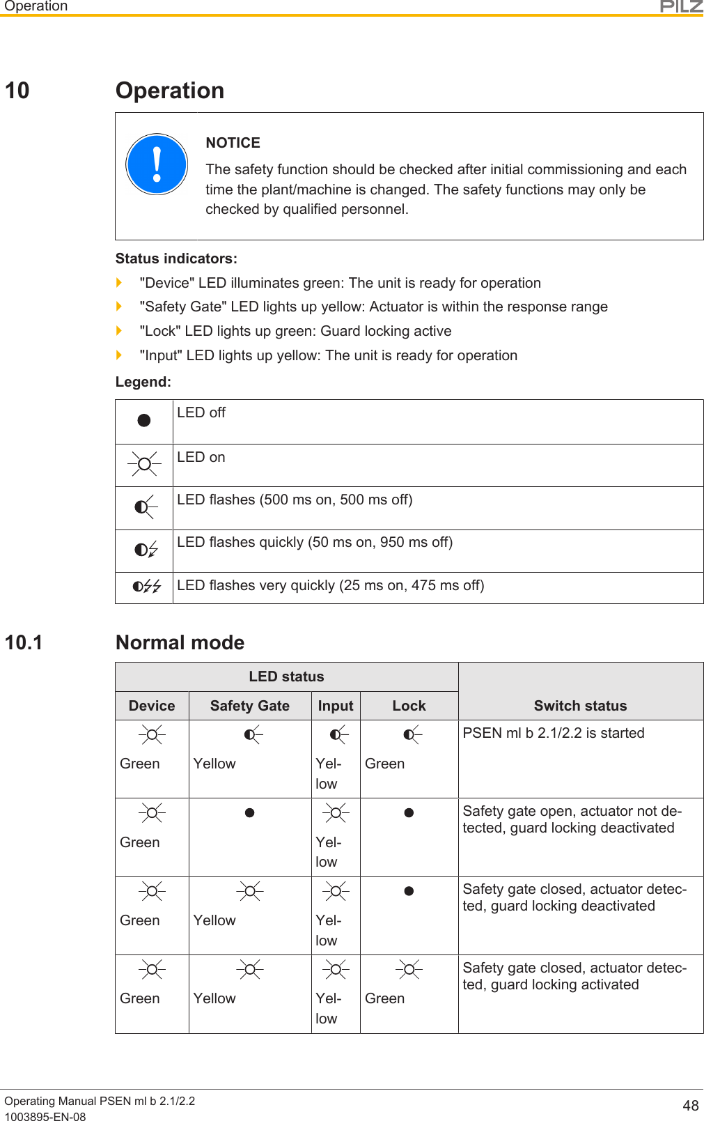
![OperationOperating Manual PSEN ml b 2.1/2.21003895-EN-08 49WarningsLED statusSwitch statusRemedy / meas-ureDevice Safety Gate Input LockGreen Yellow Yel-lowGreenSafety gateclosed, actuatordetected, guardlocking cannot beactivated / deac-tivatedCheck the actu-ator'salignment [ 47]to the safetyswitch.The supplyvoltage to safetyinputs S31 andS41 wasswitched back onbefore the auxili-ary releasescrew was turnedback.Turn back theauxiliary releasescrew and thenswitch the supplyvoltage on (seeRecommissioning [ 19]).YellowDisplay not defin-itiveYel-lowDisplay notdefinitiveSafety switchactive despiteover or under-voltageCheck the supplyvoltage.If safety inputsS31 and S41 areactivated or de-activated whilean undervoltagewarning ispresent, thesafety switchswitches to afault condition.](https://usermanual.wiki/Pilz-and-KG/PSENML.Users-Manual-PSEN-ml-b-2-1-570403-V2-0/User-Guide-3840728-Page-49.png)
![OperationOperating Manual PSEN ml b 2.1/2.21003895-EN-08 5010.2 Error displayLED status Switch status Remedy / measureDevice Safety Gate Input LockRed Yellow Yel-lowDisplay notdefinitiveSafety switch de-activated due tounder or over-voltageCheck the supply voltage andswitch the supply voltage off andthen on again.RedPrevious LED display isretainedDisplay notdefinitiveSafety outputs infault conditionCheck the wiring and switch thesupply voltage off and then onagain.RedAuxiliary release/escape releaseactivated}Auxiliary release: Turn back theauxiliary release screw and thenswitch the supply voltage on(seeRecommissioning [ 19]).}Escape release: Pull the buttonof the escape release pin backagain and then switch on thevoltage supply again (see Re-commissioning under escaperelease [ 21]).Error Please contact Pilz.RedDisplay not definitive Safety switchdoes not startChange the safety switch.Green Yellow Yel-lowDisplay notdefinitiveWrong actuator Use the actuator PSEN ml 2.1.](https://usermanual.wiki/Pilz-and-KG/PSENML.Users-Manual-PSEN-ml-b-2-1-570403-V2-0/User-Guide-3840728-Page-50.png)
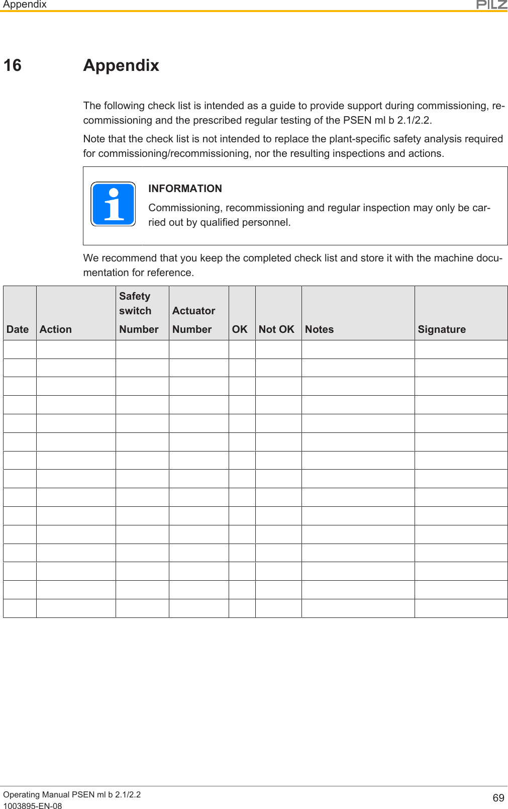
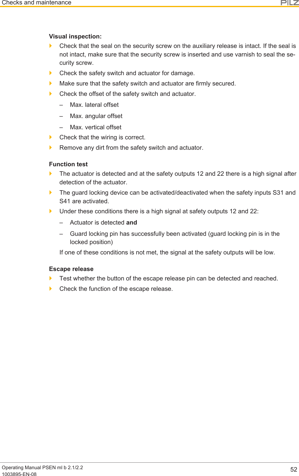
![Checks and maintenanceOperating Manual PSEN ml b 2.1/2.21003895-EN-08 5111 Checks and maintenanceRegular inspection of the switch function is required to guarantee the trouble-free, long-term function.If the interlock and guard locking system is only used rarely (opening and closing the safetygate and activating/deactivating the guard locking device), a manual function test is re-quired.The correct function of the device should be checked at regular intervals and after each er-ror.Test intervals in accordance with EN ISO 14119:}for SIL CL 3/PL e at least 1x per month}for SIL CL 2/PL d at least 1x per yearThe Appendix contains a Check list [ 69], which should help you perform the test.](https://usermanual.wiki/Pilz-and-KG/PSENML.Users-Manual-PSEN-ml-b-2-1-570403-V2-0/User-Guide-3840728-Page-51.png)
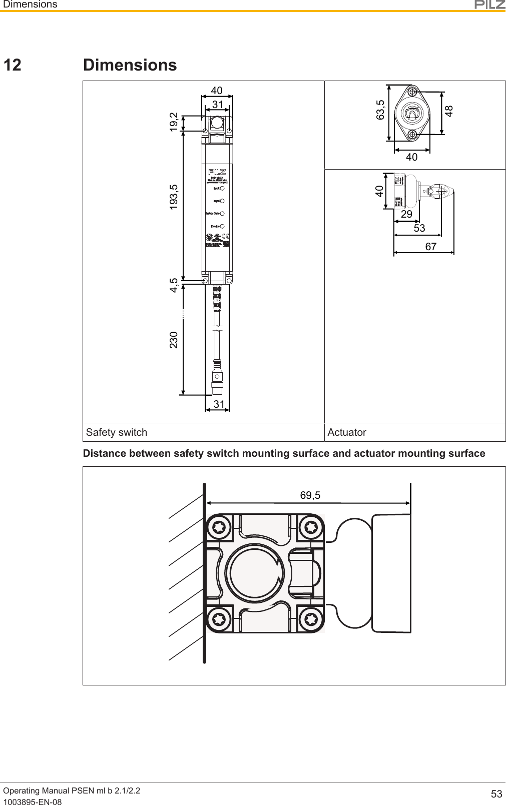
![DimensionsOperating Manual PSEN ml b 2.1/2.21003895-EN-08 54Mounting plate (see Accessories [ 66])25512,543,25193,5204,5 31280(12,5)n8,5M5n8,5M5Fig.: Order no.: 570490](https://usermanual.wiki/Pilz-and-KG/PSENML.Users-Manual-PSEN-ml-b-2-1-570403-V2-0/User-Guide-3840728-Page-54.png)
![DimensionsOperating Manual PSEN ml b 2.1/2.21003895-EN-08 55Mounting bracket for sliding gate (see Accessories [ 66])4030 1011,7540n6,5n6,563,5101060207,7548M5M5Fig.: Order no.: 570492](https://usermanual.wiki/Pilz-and-KG/PSENML.Users-Manual-PSEN-ml-b-2-1-570403-V2-0/User-Guide-3840728-Page-55.png)
![DimensionsOperating Manual PSEN ml b 2.1/2.21003895-EN-08 56Mounting bracket for swing gate (see Accessories [ 66])69,5689,54863,569,515,58,56,540Fig.: Order no.: 57049379.5689,569,515,58,56,5404863,5Fig.: Order no.: 570494](https://usermanual.wiki/Pilz-and-KG/PSENML.Users-Manual-PSEN-ml-b-2-1-570403-V2-0/User-Guide-3840728-Page-56.png)
![DimensionsOperating Manual PSEN ml b 2.1/2.21003895-EN-08 57Mounting bracket with handle unit for sliding gate (see Accessories [ 66])581040983011,754015063,5n6,52548 7,7520M5Fig.: Order no.: 570495](https://usermanual.wiki/Pilz-and-KG/PSENML.Users-Manual-PSEN-ml-b-2-1-570403-V2-0/User-Guide-3840728-Page-57.png)
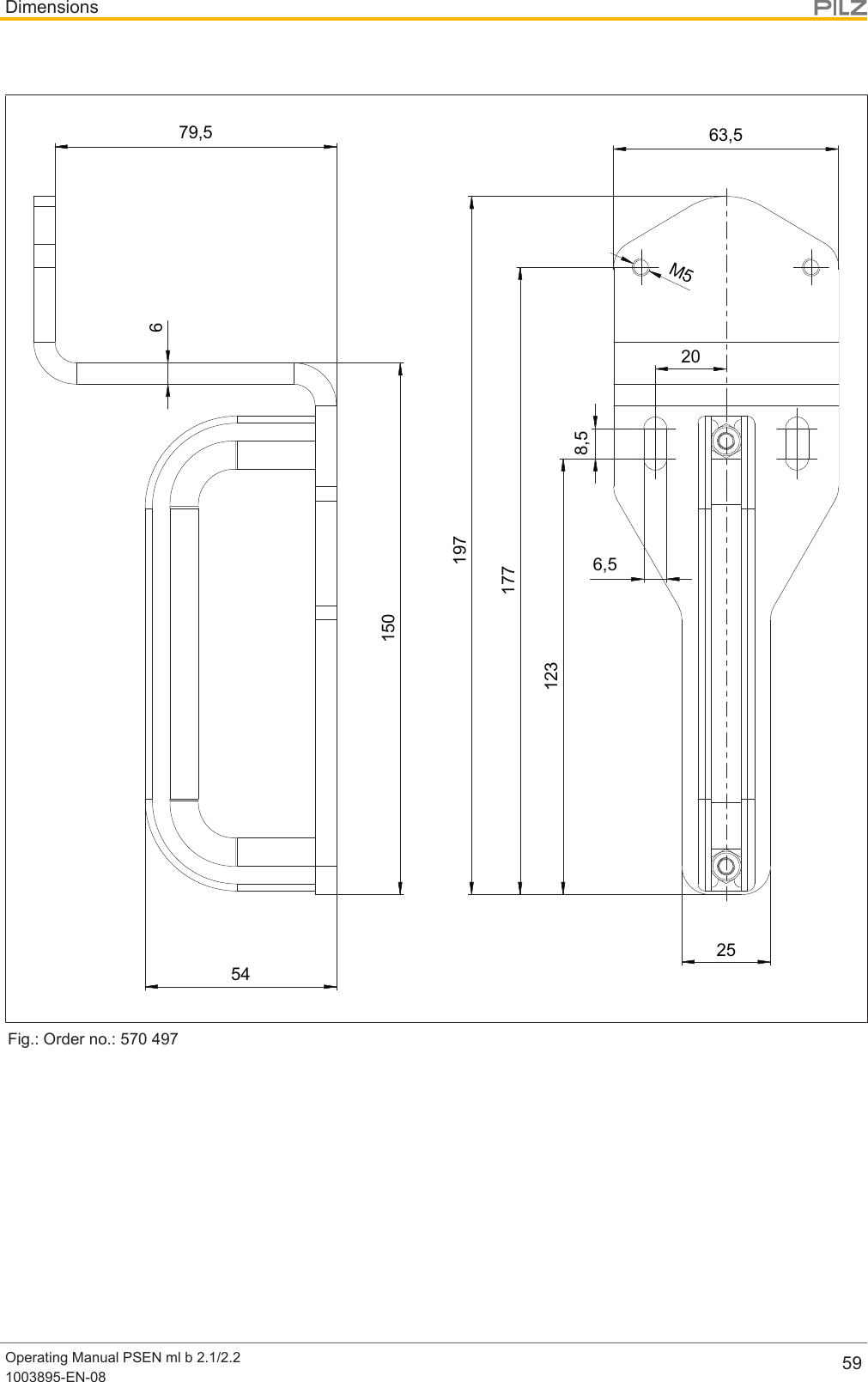
![DimensionsOperating Manual PSEN ml b 2.1/2.21003895-EN-08 58Mounting bracket with handle unit for swing gate (see Accessories [ 66])19769,517768,56,5123150M5205463,525Fig.: Order no.: 570496](https://usermanual.wiki/Pilz-and-KG/PSENML.Users-Manual-PSEN-ml-b-2-1-570403-V2-0/User-Guide-3840728-Page-58.png)
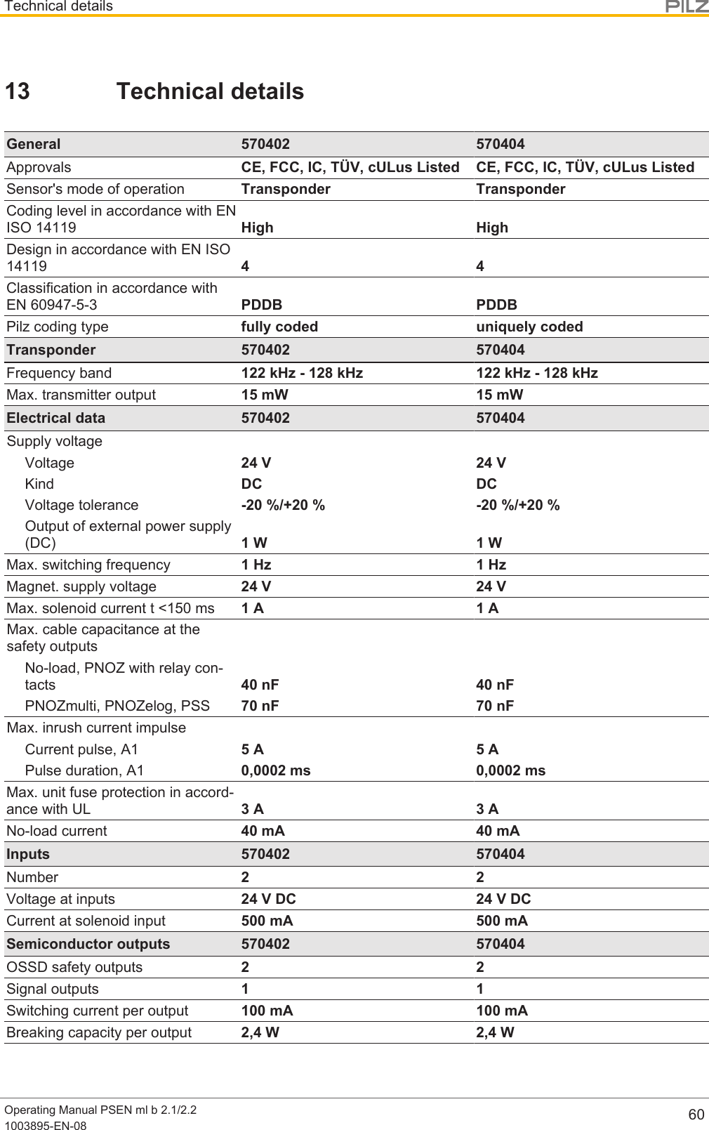
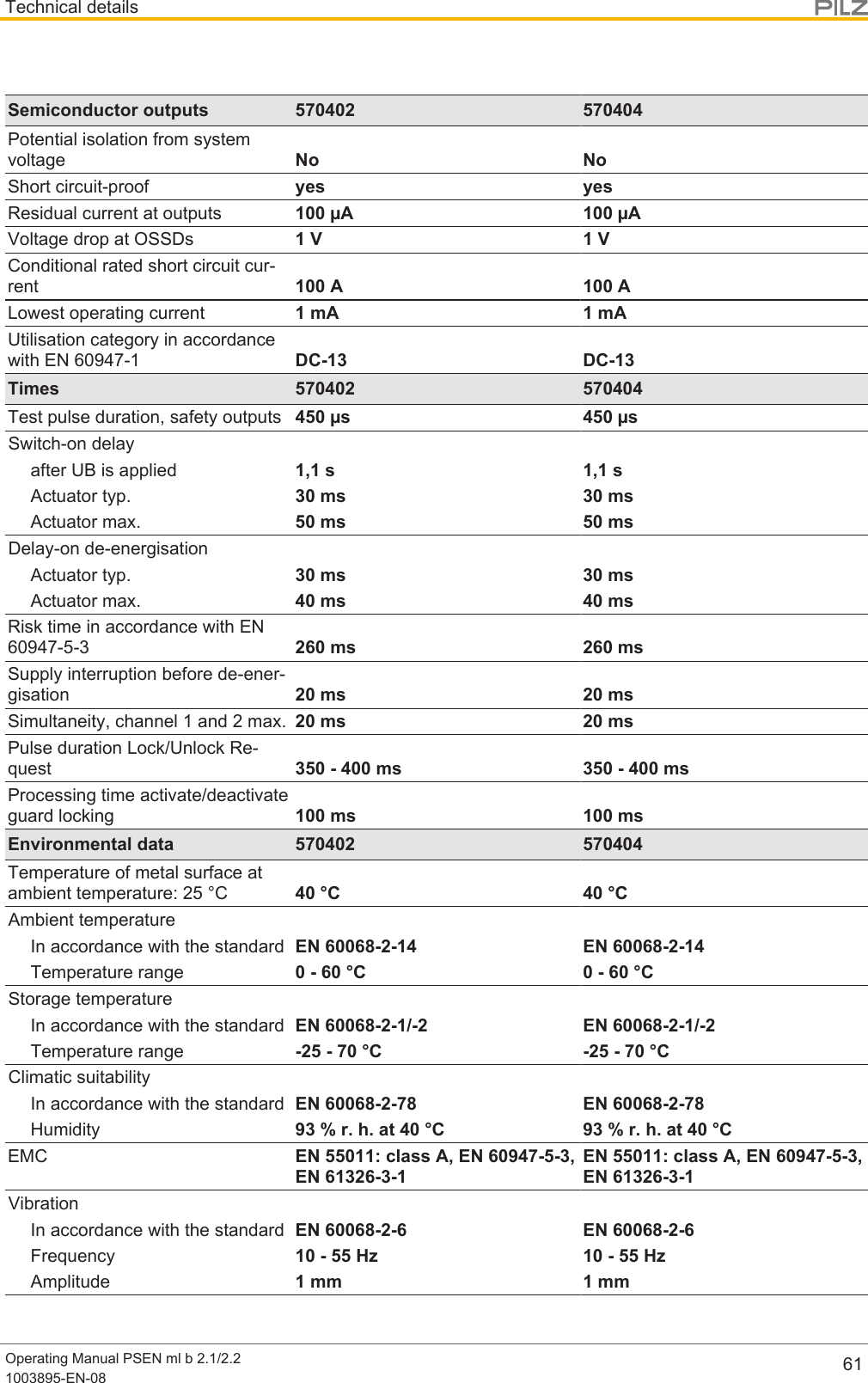
![Technical detailsOperating Manual PSEN ml b 2.1/2.21003895-EN-08 64Safe 1-pole HL outputsSource DrainSafety switch C2 Evaluation device C1, C2Source parameters Min. Typ. Max.Test impulse duration - - 450 µsRated current - - 0,1 ACapacitive load - - 70 nF13.2 Safety characteristic dataNOTICEYou must comply with the safety characteristic data in order to achieve therequired safety level for your plant/machine.OperatingmodeEN ISO13849-1:2015PLEN ISO13849-1:2015CategoryEN IEC62061SIL CLEN IEC62061PFHD [1/h]Lambda d/LambdaEN ISO13849-12015, ENIECB10DEN ISO13849-1:2015TM [year]1-ch. guardlocking PL d Cat. 2 SIL CL 2 4,22E-09 ––202-ch. guardlocking PL e Cat. 4 SIL CL 3 4,22E-09 ––202-ch. OSSD PL e Cat. 4 SIL CL 3 2,38E-09 ––20All the units used within a safety function must be considered when calculating the safetycharacteristic data.INFORMATIONA safety function's SIL/PL values are not identical to the SIL/PL values ofthe units that are used and may be different. We recommend that you usethe PAScal software tool to calculate the safety function's SIL/PL values.NOTICEBe sure that you observe the mechanical life. The safety characteristic dataare only valid as long as the values of mechanical life are met.](https://usermanual.wiki/Pilz-and-KG/PSENML.Users-Manual-PSEN-ml-b-2-1-570403-V2-0/User-Guide-3840728-Page-64.png)