Pilz and KG PSENML RFID Proximity switch User Manual PSEN ml s 1 1 Operat Man 1004670 EN
Pilz GmbH & Co. KG RFID Proximity switch PSEN ml s 1 1 Operat Man 1004670 EN
Contents
Users Manual PSEN ml s 1.1_570407_V2.0

PSEN ml s 1.1
Operating Manual-1004670-EN-01
}PSEN sensor technology

Preface
This document is the original document.
All rights to this documentation are reserved by Pilz GmbH & Co. KG. Copies may be made
for the user's internal purposes. Suggestions and comments for improving this documenta-
tion will be gratefully received.
Source code from third-party manufacturers or open source software has been used for
some components. The relevant licence information is available on the Internet on the Pilz
homepage.
Pilz®, PIT®, PMI®, PNOZ®, Primo®, PSEN®, PSS®, PVIS®, SafetyBUS p®,
SafetyEYE®, SafetyNET p®, the spirit of safety® are registered and protected trademarks
of Pilz GmbH & Co. KG in some countries.
SD means Secure Digital
Contents
Operating Manual PSEN ml s 1.1
1004670-EN-01 3
Section 1 Introduction 5
1.1 Validity of documentation 5
1.2 Using the documentation 5
1.3 Definition of symbols 5
Section 2 Safety 7
2.1 Intended use 7
2.2 Safety regulations 8
2.2.1 Safety assessment 8
2.2.2 Additional documents that apply 8
2.2.3 Use of qualified personnel 8
2.2.4 Warranty and liability 9
2.2.5 Disposal 9
2.3 For your safety 9
Section 3 Overview 10
3.1 Unit features 10
3.2 Scope of supply 10
Section 4 Function description 11
4.1 Structure 11
4.2 Activation of safety inputs S31 and S41 (solenoid operation) 12
4.2.1 Activation with specification of direction 14
4.2.2 Activation without specification of direction 14
4.3 Safety Device Diagnostics 15
4.4 Operating modes 15
4.5 Block diagram 19
4.6 Auxiliary release 19
4.6.1 Recommissioning 21
4.7 Prevent restart 21
4.8 Escape release 22
4.8.1 Recommissioning 23
Section 5 Wiring 24
5.1 Important information 24
5.2 Pin assignment, connector and cable 24
5.3 EMC requirements 25
Section 6 Connection to control systems and evaluation devices 26
6.1 Important information 26
6.2 Minimum requirements for activation of guard locking 26
6.3 Single connection 28
6.4 Series connection 29
6.5 Connection to Pilz evaluation devices 32
6.5.1 Connection example with PNOZmulti and Safety Device Diagnostics 33

Contents
Operating Manual PSEN ml s 1.1
1004670-EN-01 4
Section 7 Teaching in the actuator 34
7.1 PSEN ml 1.1 34
Section 8 Installation 35
8.1 Important information 35
8.2 Tapped hole 36
8.3 Install fixing screws in parallel to actuator 38
8.4 Install fixing screws side-on to actuator 38
8.5 Centre the bolt in the actuator housing 39
8.6 Rotate the bolt in the actuator housing 90° 39
8.7 Installation on sliding gate 41
8.8 Installation on swing gate 42
8.9 Installation with mounting bracket 44
8.10 Installation with mounting plate 44
8.11 Installing the escape release 45
8.11.1 Important information 45
8.11.2 Installation positions for escape release 46
8.11.3 Installation stationary escape release 47
8.11.4 Installation external escape release 49
8.11.5 Uninstalling the escape release 52
Section 9 Adjustment 53
Section 10 Operation 54
10.1 Normal mode 54
10.2 Error display 56
Section 11 Checks and maintenance 57
Section 12 Dimensions 58
Section 13 Technical details 65
13.1 Classification according to ZVEI, CB24I 68
13.2 Safety characteristic data 69
Section 14 Supplementary data 70
14.1 Radio approval 70
14.2 Technical details for mounting bracket without handle unit 70
14.3 Technical details for mounting bracket with handle unit 70
Section 15 Order reference 71
15.1 System 71
15.2 Accessories 71
Section 16 Appendix 75
Section 17 EC declaration of conformity 76
Introduction
Operating Manual PSEN ml s 1.1
1004670-EN-01 5
1 Introduction
1.1 Validity of documentation
This documentation is valid for the product PSEN ml s 1.1 from Version 2.0.
This operating manual explains the function and operation, describes the installation and
provides guidelines on how to connect the product.
1.2 Using the documentation
This document is intended for instruction. Only install and commission the product if you
have read and understood this document. The document should be retained for future ref-
erence.
1.3 Definition of symbols
Information that is particularly important is identified as follows:
DANGER!
This warning must be heeded! It warns of a hazardous situation that poses
an immediate threat of serious injury and death and indicates preventive
measures that can be taken.
WARNING!
This warning must be heeded! It warns of a hazardous situation that could
lead to serious injury and death and indicates preventive measures that can
be taken.
CAUTION!
This refers to a hazard that can lead to a less serious or minor injury plus
material damage, and also provides information on preventive measures
that can be taken.
NOTICE
This describes a situation in which the product or devices could be dam-
aged and also provides information on preventive measures that can be
taken. It also highlights areas within the text that are of particular import-
ance.

Introduction
Operating Manual PSEN ml s 1.1
1004670-EN-01 6
INFORMATION
This gives advice on applications and provides information on special fea-
tures.

Safety
Operating Manual PSEN ml s 1.1
1004670-EN-01 7
2 Safety
2.1 Intended use
The safety gate system is used for interlocking and guard locking swing gates and sliding
gates.
The safety gate system can be operated in two ways:
}Unlocking with condition
The safety gate system prevents the safety gate from being unlocked while there is any
hazard within the danger zone.
}Unlocking without condition
The operator can unlock the safety gate system at any time. After starting the unlock-
ing, the guard locking creates a stop command. The time required to unlock the inter-
locking guard has to be longer than the time required to stop the hazardous machine
function.
The hazardous machine function may only be executed under the following conditions:
}There is a high signal at safety outputs 12 and 22 and
}There is a low signal at safety outputs S31 (Lock/Unlock Request 1) and S41 (Lock/Un-
lock Request 2).
Safety inputs S31 and S41 (solenoid operation) may only be operated under the following
condition:
}Plant is in a safe condition
Make sure that this is the case with an AND operation in the safety system immediately
before the output is operated.
The safety switch meets the requirements in accordance with:
}EN 60947-5-3 with the actuator PSEN ml 1.1: PDDB
}EN 62061: SIL CL 3
}EN ISO 13849-1: PL e (Cat. 4 )
}ENISO14119: Coding level Low, type 4
The safety switch may only be used with the corresponding actuator PSEN ml 1.1.
The safety level PL e (Cat. 4 )/SIL CL 3 is only achieved if
}the safety outputs use 2-channel processing
}The solenoid has 2-channel operation via safe, tested outputs, suitable for PL e (Cat.
4)/SIL CL 3 applications.
With 1-channel operation of the safety inputs S31 (Lock/Unlock Request 1) and S41 (Lock/
Unlock Request 2) it is only possible to achieve safety level PLd(Cat.2)/SILCL2.
Foreseeable misuse
}Safety switches and actuators of the safety gate system PSEN ml s 1.1 must not be
used as mechanical limit stops
}Use of the PSEN ml s 1.1 under corrosive environmental conditions (cooling emulsions,
surface treatment, gases, …)
Please contact Pilz.

Safety
Operating Manual PSEN ml s 1.1
1004670-EN-01 8
2.2 Safety regulations
2.2.1 Safety assessment
Before using a device it is necessary to perform a safety assessment in accordance with
the Machinery Directive.
Functional safety is guaranteed for the product as a single component. However, this does
not guarantee the functional safety of the overall plant/machine. In order to achieve the re-
quired safety level for the overall plant/machine, define the safety requirements for the
plant/machine and then define how these must be implemented from a technical and organ-
isational standpoint.
2.2.2 Additional documents that apply
Please read and take note of the following documents.
Only for use of the Safety Device Diagnostics (SDD):
}Operating manual for the fieldbus module, for example SDD ES ETH or SDD ES
PROFIBUS
}System description "Safety Device Diagnostics"
For the use of passive junctions:
}Operating manual of a passive junction, for example:
– PSEN ix2 F4 code
– PSEN ix2 F8 code
– PDP67 F 4 code
You will need to be conversant with the information in these documents in order to fully un-
derstand this operating manual.
2.2.3 Use of qualified personnel
The products may only be assembled, installed, programmed, commissioned, operated,
maintained and decommissioned by competent persons.
A competent person is a qualified and knowledgeable person who, because of their train-
ing, experience and current professional activity, has the specialist knowledge required. To
be able to inspect, assess and operate devices, systems and machines, the person has to
be informed of the state of the art and the applicable national, European and international
laws, directives and standards.
It is the company’s responsibility only to employ personnel who
}Are familiar with the basic regulations concerning health and safety / accident preven-
tion,
}Have read and understood the information provided in the section entitled Safety
}Have a good knowledge of the generic and specialist standards applicable to the spe-
cific application.
Safety
Operating Manual PSEN ml s 1.1
1004670-EN-01 9
2.2.4 Warranty and liability
All claims to warranty and liability will be rendered invalid if
}The product was used contrary to the purpose for which it is intended,
}Damage can be attributed to not having followed the guidelines in the manual,
}Operating personnel are not suitably qualified,
}Any type of modification has been made (e.g. exchanging components on the PCB
boards, soldering work etc.).
2.2.5 Disposal
}In safety-related applications, please comply with the mission time TM in the safety-re-
lated characteristic data.
}When decommissioning, please comply with local regulations regarding the disposal of
electronic devices (e.g. Electrical and Electronic Equipment Act).
2.3 For your safety
WARNING!
Loss of safety function due to substituting an actuator from the interlocking
and guard locking system
Substituting an actuator for an inappropriate actuator may lead to serious in-
jury and death.
– You should prevent the interlocking and guard locking system from
being manipulated with an inappropriate actuator.
– Keep the substitute actuator in a safe place and protect it from unau-
thorised access.
– If substitute actuators are used, these must be installed as described
under Installation [ 35]
– If the original actuators are replaced with substitute actuators, the ori-
ginal actuators must be destroyed before disposal.
}Do not remove the connector's protective cap until you are just about to connect the
unit. This will prevent potential contamination.

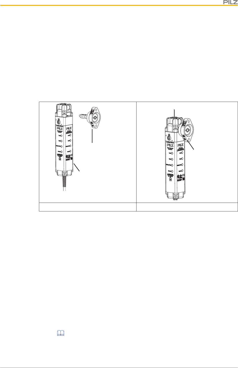
Overview
Operating Manual PSEN ml s 1.1
1004670-EN-01 10
3 Overview
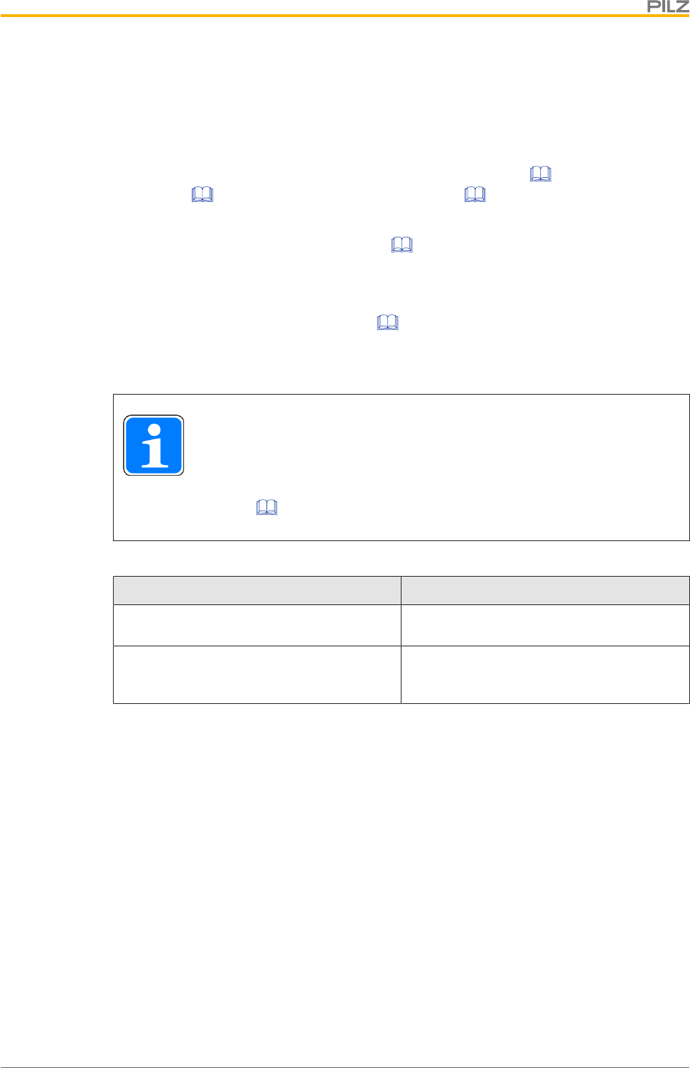
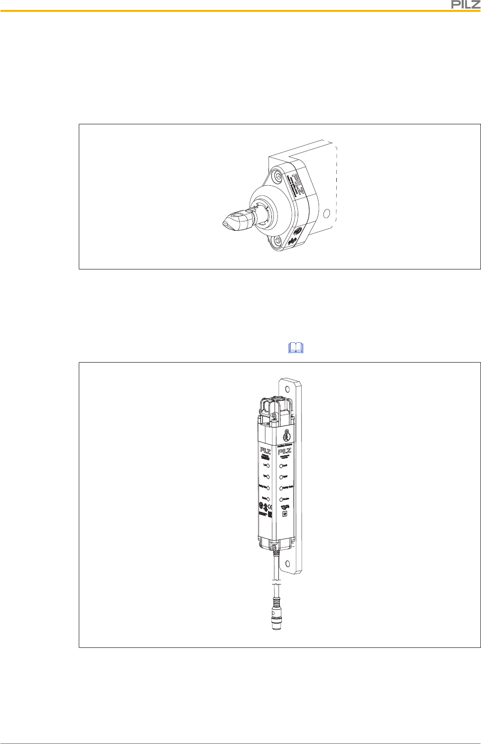
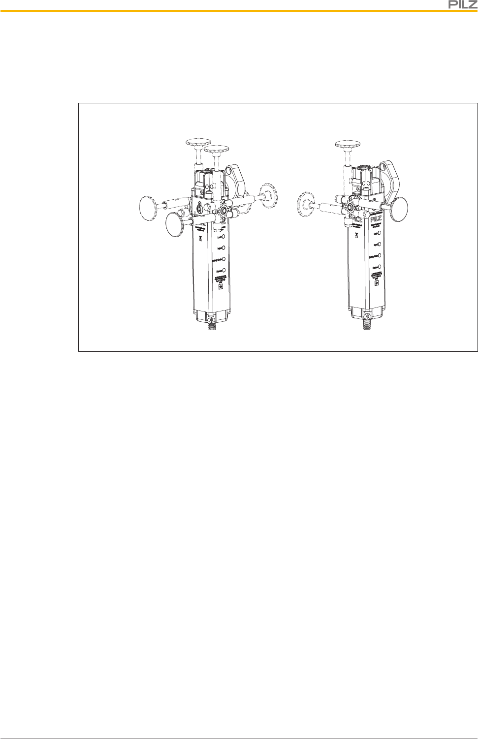
3.1 Unit features
}Safe guard locking for swing gates and sliding gates
}Safe interlocking (position monitoring)
}Transponder technology
}2 safety inputs for series connection of multiple safety switches
}2 safety outputs
}Safety Device Diagnostics (SDD)
– Safety Device Diagnostics can be used to poll sensor information, to perform ac-
tions and to read configuration parameters
– Manipulation protection in accordance with ISO 14119 (chap. 7.2.d) is possible by
verifying the short name of the actuator through the controller via SDD communica-
tion
}Diagnostic input for Y1 for Safety Device Diagnostics (SDD)
}Signal output/diagnostic output Y32 for Safety Device Diagnostics
}Monitoring of shorts between the safety outputs
}Guard locking element keeps the safety gate from being opened unintentionally
}Auxiliary release for opening the safety gate
}1 signal output
}Suitable for left and right hinged safety gates
}Pilz coding type: Coded
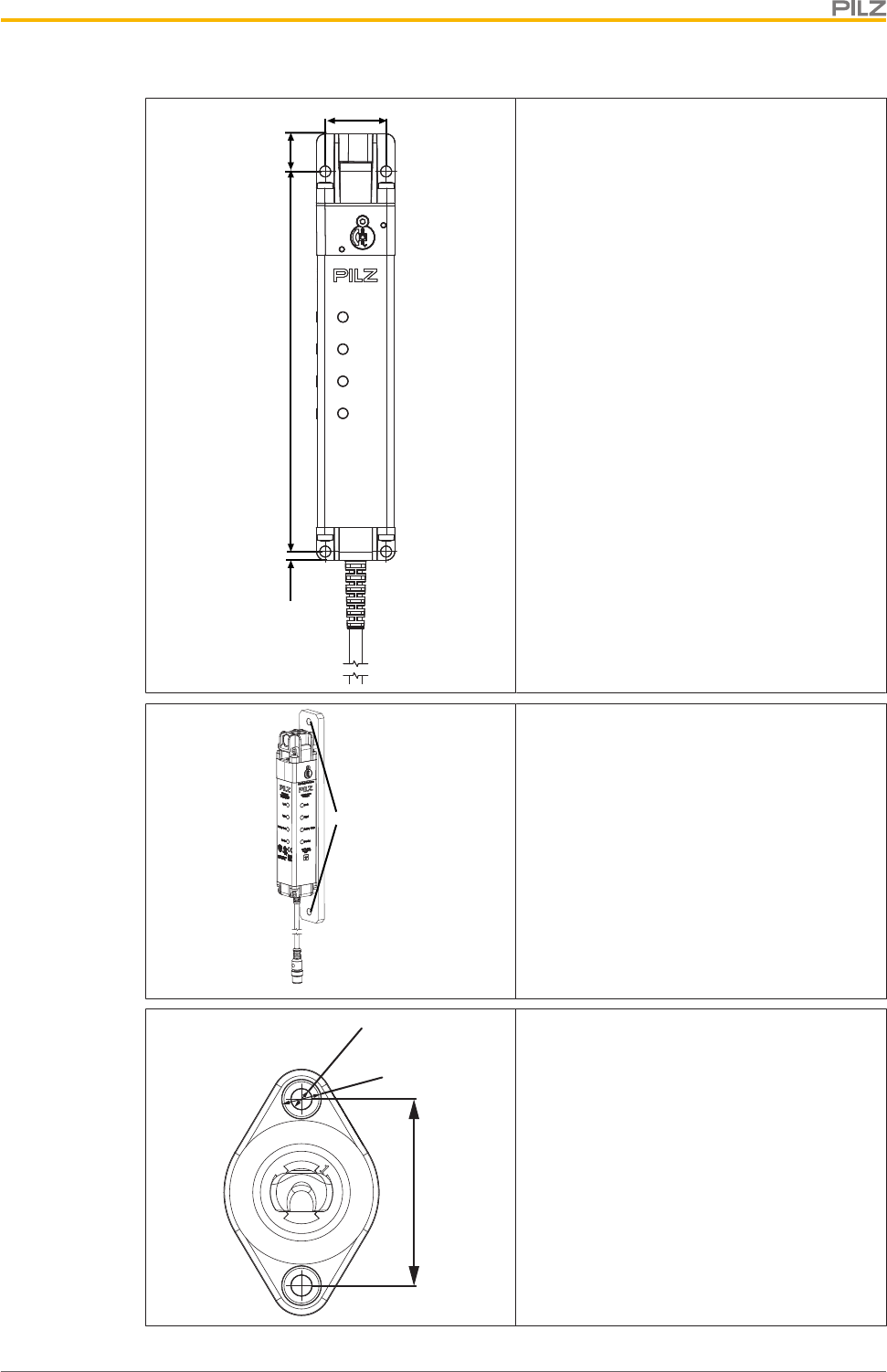
}M12, 12-pin male connector
}LEDs:
– Supply voltage/fault
– Status of actuator
– Status of guard locking
– Status of safety inputs S11 and S21
}The bolt in the actuator can be rotated 90° in the actuator housing before the actuator is
installed. As a result, the actuator can be installed vertically or horizontally.
}The safety switch PSEN ml s 1.1 can be expanded using a stationary or external es-
cape release (see Order reference: Accessories [ 71]).
The stationary escape release can be expanded by 25 mm max. two times.
The external escape releases are available with push/pull cables between 1.5and4m
in length (grading 50cm).
3.2 Scope of supply
}Scope of supply PSEN ml s 1.1
– Safety switch PSEN ml s 1.1
– Actuator
Function description
Operating Manual PSEN ml s 1.1
1004670-EN-01 11
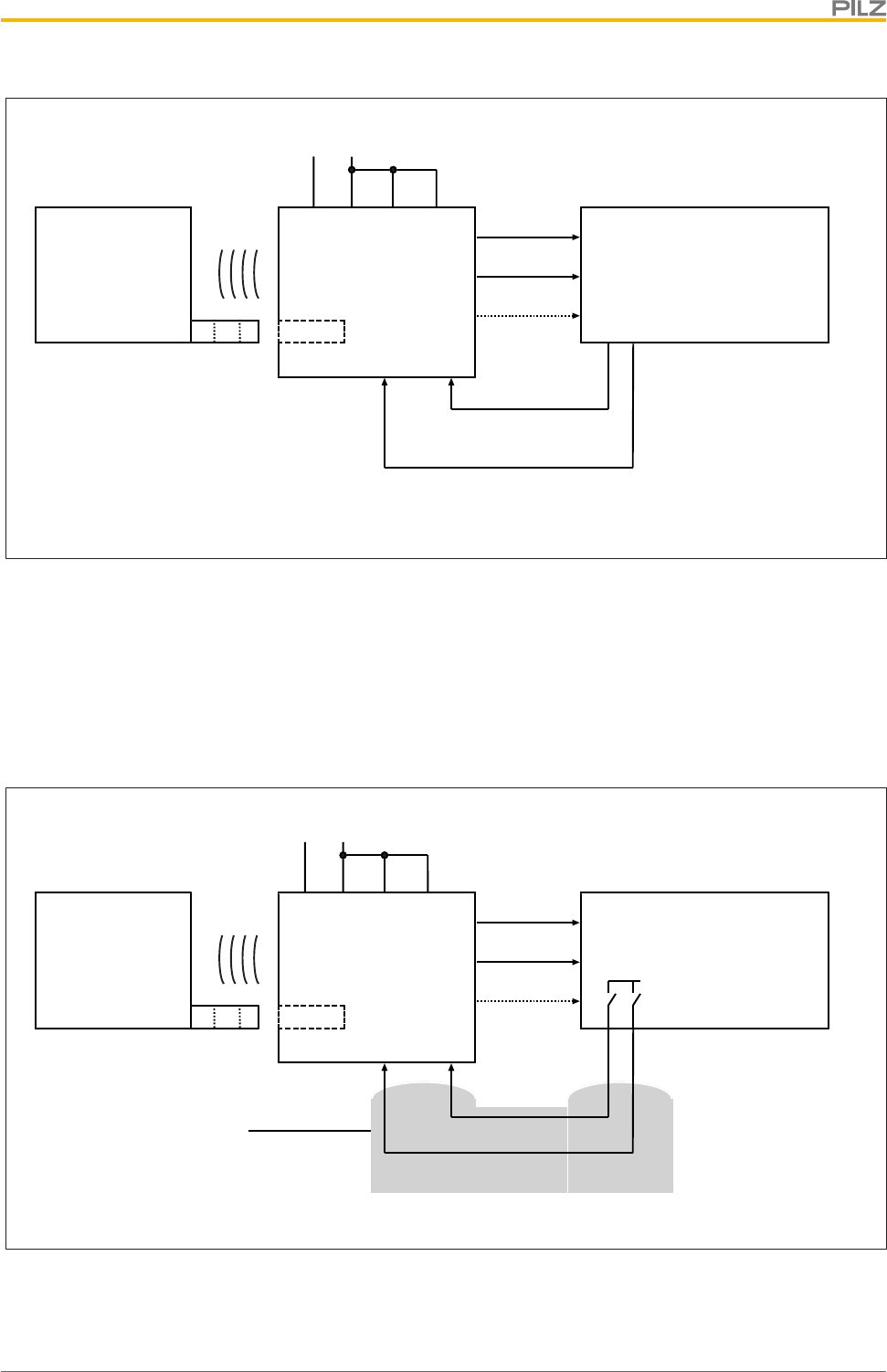
4 Function description
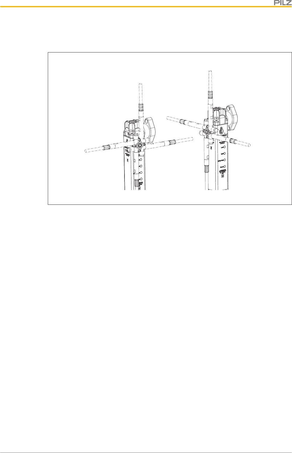
4.1 Structure
The interlocking and guard locking system prevents the safety gates to the danger zone
from being opened while there is any hazard within the danger zone (machine movement,
voltage, ...).
The safety outputs may have a high or low signal, depending on the position of the actuator
and the signal path of safety inputs S31 and S41 (solenoid operation).
Safety switch
Actuator
Safety switch
Actuator
Gate open Gate closed
Safety outputs 12 and 22
Under these conditions there is a high signal at safety outputs 12 and 22:
}Actuator is detected and
}Guard locking pin has successfully been activated (guard locking pin is in the locked
position) and
}There is a high signal at the inputs S11 and S21
If one of these conditions is not met, the signal at the safety outputs will be low.
Feasibility monitoring for safety inputs S11 and S21
}If one safety input switches from high to low, while the other safety input remains high,
an unequal status is displayed: Input LED flashes yellow
}If this safety input switches back from low to high, while the other safety input remains
high, a feasibility error is displayed and a partial operation lock is triggered: Input LED
flashes yellow
A switch to a high signal will only lead to normal switch operation if both inputs had a low
signal. From this moment on, the switch to high may occur (partial operation lock see Error
display [ 56]).
Function description
Operating Manual PSEN ml s 1.1
1004670-EN-01 12
}Diagnostic input Y1
If a fieldbus module of the SDD is used, the diagnostic input Y1 is automatically activ-
ated and data is read.
If no fieldbus module of the SDD is used, the diagnostic input Y1 is not used.
}Signal output/diagnostic output Y32
The status of the actuator is output. If a fieldbus module of the SDD is used, the signal
output/diagnostic output for the writing of data is activated.
4.2 Activation of safety inputs S31 and S41 (solenoid operation)
}If there is a low signal at safety inputs S31 and S41, the guard locking pin does not
change its position.
}Guard locking may only be deactivated once the hazardous movement has been com-
pleted.
Active use of Safety Device Diagnostics
}The safety inputs S31 and S41 have a high signal within max. 500 ms after the receipt
of the guard locking activation.
Single connection
Guard locking is activated through a high signal (length 350 - 400 ms ) at inputs S31 and
S41 (solenoid operation). After activation, the inputs must be low. Another pulse (length
350 - 400 ms ) at these inputs deactivates guard locking.
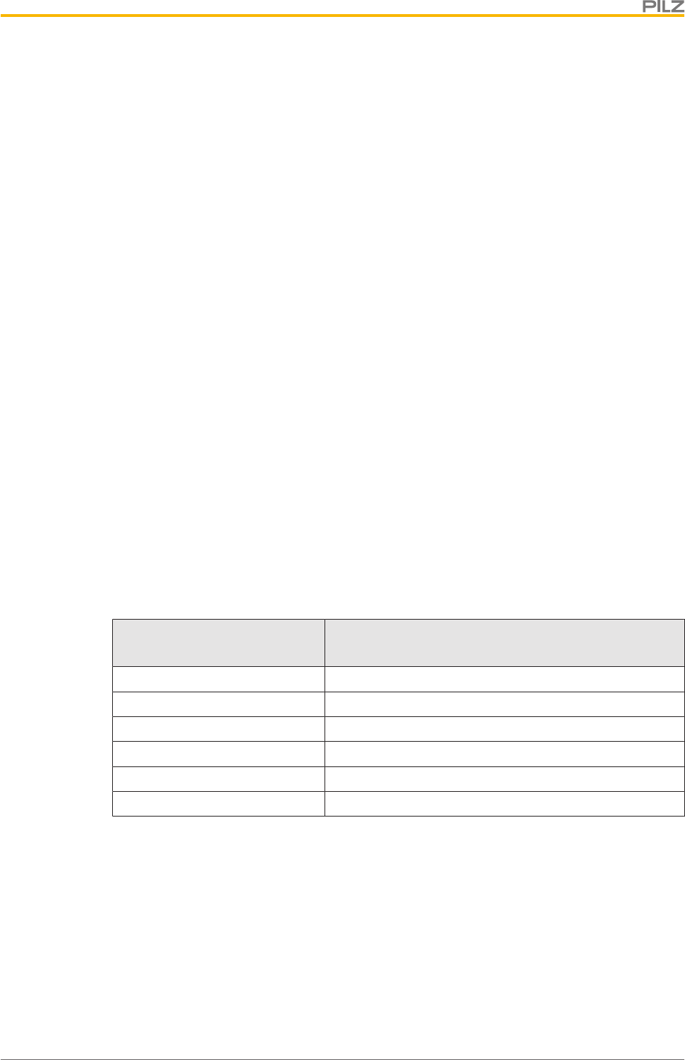
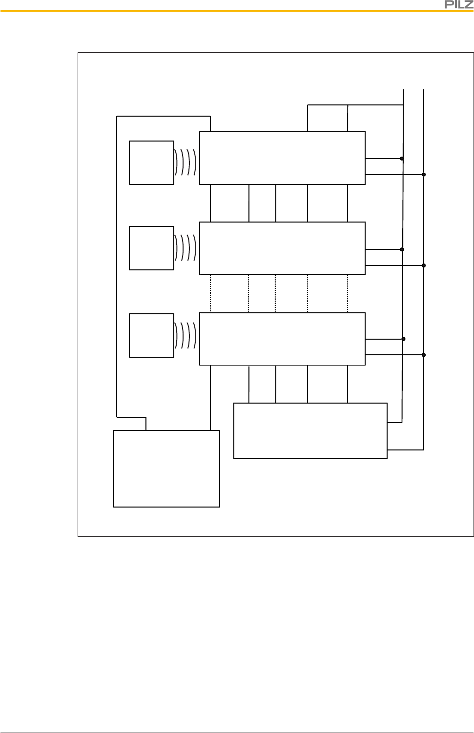
Series connection
In a series connection with n safety switches the safety lock is activated by a high signal
with a minimum length of t=n*(350 - 400 ms) at the inputs S31 and S41 (solenoid opera-
tion).
Number of safety switches in
the series connection Pulse duration Lock/Unlock Request in ms
1 350
2 700
3 1050
4 1400
5 1750
6 2100
After activation, the inputs must be low. Another pulse of the specified length at these in-
puts deactivates guard locking.
Function description
Operating Manual PSEN ml s 1.1
1004670-EN-01 13
3 x PSEN ml s
X1 X2
X3
X1 X2
X3
X1
X2
Safety control system
8-core
12-core
[1] [2]
Legend
[1] PSEN ml Y junction M12
[2] PSEN ml end adapter
}Series connection of the OSSD outputs
S21 S11 12 22 S21 S11 12 22
1. PSEN ml 2. PSEN ml
}Series connection of diagnostics with Safety Device Diagnostics
Y1 Y32 Y1 Y32
1. PSEN ml 2. PSEN ml
Fieldbus module
}Series connection of the solenoid operation
Function description
Operating Manual PSEN ml s 1.1
1004670-EN-01 14
S31 S41 32 42 S31 S41 32 42
1. PSEN ml 2. PSEN ml
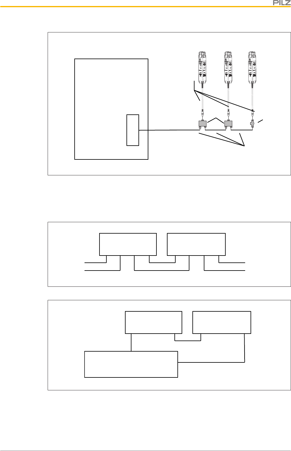
4.2.1 Activation with specification of direction
}The guard locking is activated when the time between the rising edges from S31 to S41
is between 40ms and 500ms (S31 before S41).
}The guard locking is deactivated when the time between the rising edges from S31 to
S41 is between 40ms and 500ms (S41 before S31).
S31
S41
tmax
Guard locking
S31
S41
tmax
Guard locking
Legend
tmax Maximum time between the rising edges from S31 and S42
4.2.2 Activation without specification of direction
}The guard locking changes its state when the time between the rising edges from S31
and S41<20ms.

Function description
Operating Manual PSEN ml s 1.1
1004670-EN-01 15
4.3 Safety Device Diagnostics
Safety Device Diagnostics is an option that can be selected independently of the safety-re-
lated wiring.
When using the Safety Device Diagnostics, up to 16 sensors connected in series can be
connected as a subscriber to a fieldbus module.
The communication of the sensors with the fieldbus module is automatically built up again
with each new supply of the supply voltage. As a result, a sensor can be exchanged, e.g.
when servicing, without the need for special measures.
An exchange can be detected via the fieldbus module e.g. through the serial number.
}With Safety Device Diagnostics there are the following diagnostic options for the field-
bus module:
– Poll information of the sensors (examples: what sensor in the series has switched,
at what point could there be an open circuit in the series connection)
– Read configuration parameters of the sensor (examples: Number of teach-in pro-
cesses remaining, serial number of the switch)
– Perform actions (example: poll updated actuator name)
– Selectively activate or deactivate guard locking of individual PSEN ml within a
series connection
The results of the sensor diagnostics can be checked already during the installation phase
via the display in the fieldbus module, without the need to connect the fieldbus module to
the network.
}With Safety Device Diagnostics there are the following diagnostic options for the field-
bus module for simple wiring:
– Information is passed on via the fieldbus module directly to the network
– Mappings of the signal outputs to the sensor are automated by the SDD.
This prevents wiring errors and an expansion or reduction of the sensors is possible
without the need to change existing wiring.
– Wiring in accordance with IP20: Rapid installation in the control cabined is enabled.
– Wiring in accordance with IP67: Various passive junctions can be used (see Order
references for accessories [ 71]) to connect several sensors with only one
cable from the field in the control cabinet.
Further information on Safety Device Diagnostics can be found in Additional documents
that apply [ 8].
4.4 Operating modes
The safety switch can be used in various operating modes.
}Operation without safety device diagnostics
– Standard operating mode
After every restart the safety switch is in operation without Safety Device Dia-
gnostics.
– No communication with Safety Device Diagnostics

Function description
Operating Manual PSEN ml s 1.1
1004670-EN-01 16
– Activating/deactivating the guard locking is only via the signals S31 and S41
}Operation with passive use of the Safety Device Diagnostics
– Safety switch supplies diagnostic data to Safety Device Diagnostics
– Activating/deactivating the guard locking is only via the signals S31 and S41
}Operation with active use of the Safety Device Diagnostics
– Activate/deactivate the guard locking by a combination of a Safety Device Dia-
gnostics command and the status of the safety inputs S31 and S41 (S31 and S41
must have a high signal).
The safety requirements are guaranteed by the signals S31 and S41 (the fieldbus
for Safety Device Diagnostics communication is not safe).
}Operation with specification of direction when activating/deactivating he guard locking
A specification of direction can be used to control the change of the guard locking
status.
– Toggling: The safety switch changes with each simultaneous controlling of S31 and
S41 the guard locking status (activated <-> deactivated).
– Force Direction: The safety switch is selectively activated or deactivated by offset
activation of the rising edges of S31 and S41.
Function description
Operating Manual PSEN ml s 1.1
1004670-EN-01 17
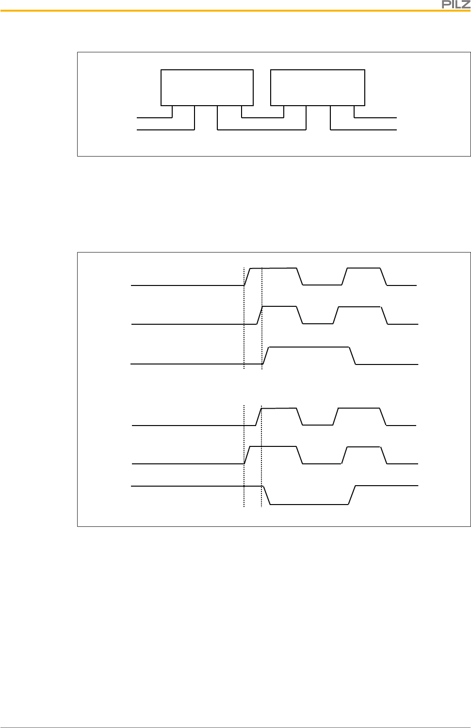
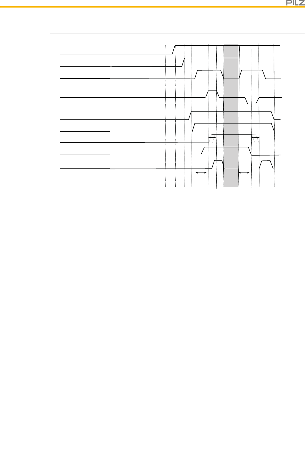
Timing diagrams
66
<
[1] [4] [5]
>@
[8] [9][7]
[t1] [t1]
[t2]
[t2]
<
66
[2] [3]
32 + 42
[10]
Guard locking
Actuator
Fig.: Passive use of the Safety Device Diagnostics
Legend
[1] Gate is open
[2] The door connected upstream in the series connection is closed
[3] The door connected upstream in the series connection is locked
[4] Gate is closed
[5] Guard locking is activated by the programmable safety system
[6] Guard locking is activated
[7] Execution of the hazardous machine function is permitted
[8] Outputs will be deactivated
[9] Guard locking will be deactivated
[10] Gate is open
[t1] Processing time of guard locking signal = 100 ms
[t2] Time window for changing guard locking status
Function description
Operating Manual PSEN ml s 1.1
1004670-EN-01 18
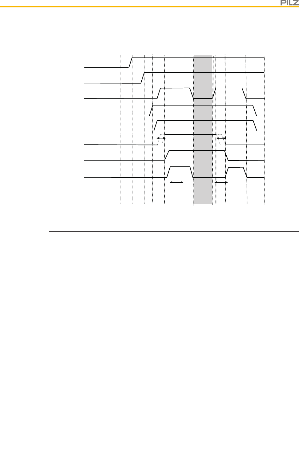
[7]
66
<
[1] [4] [5] [8] [9]
[t1] [t1]
[t2]
>@
[t2]
<
66
[2] [3]
32 + 42
[10]
SDD command guard locking
Guard locking
Actuator
Fig.: Active use of Safety Device Diagnostics
Legend
[1] Gate is open
[2] The door connected upstream in the series connection is closed
[3] The door connected upstream in the series connection is locked
[4] Gate is closed
[5] Guard locking is activated by the programmable safety system
[6] Guard locking is activated
[7] Execution of the hazardous machine function is permitted
[8] Outputs will be deactivated
[9] Guard locking will be deactivated
[10] Gate is open
[t1] Processing time of guard locking signal = 100 ms
[t2] Time window for changing guard locking status
Function description
Operating Manual PSEN ml s 1.1
1004670-EN-01 19
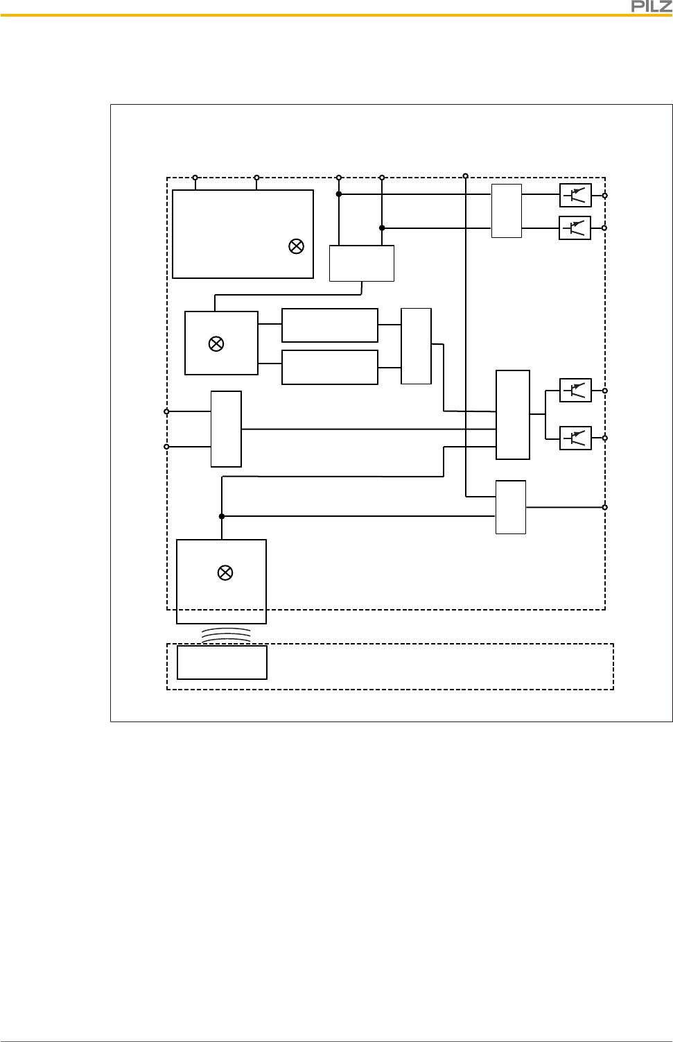
4.5 Block diagram
Actuator
A1 A2
12
22
&
S31 S41
UB
Device
Receiver
Safety Gate
Magnet
Lock
Power
Y32
Lock Sensor 1
Lock Sensor 2
&
Y1
S11
S21
32
42
&
&
&
&
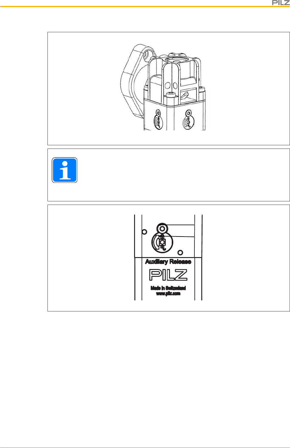
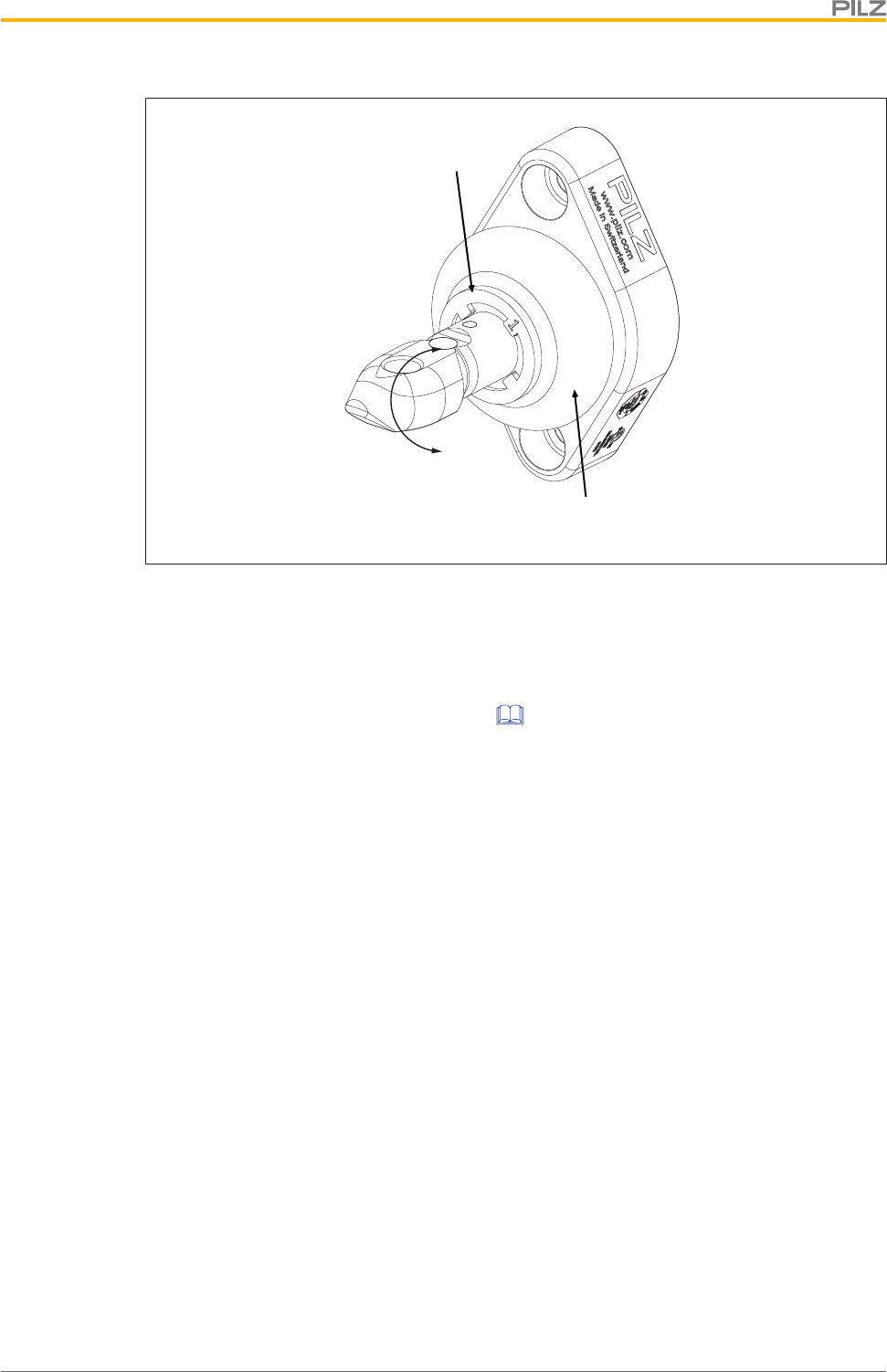
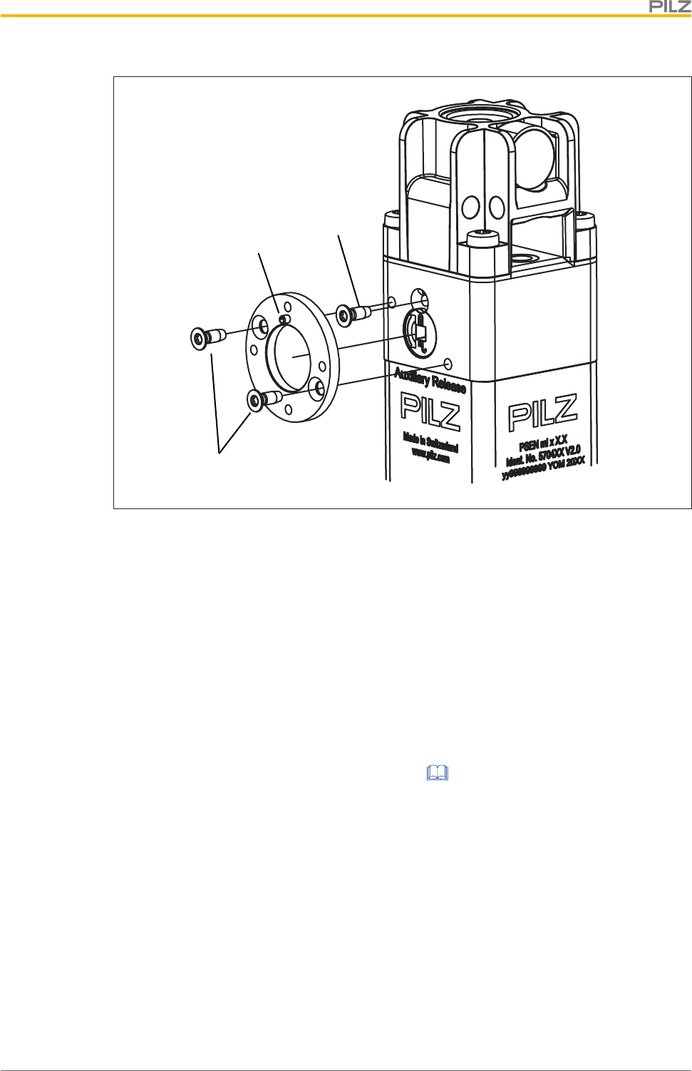
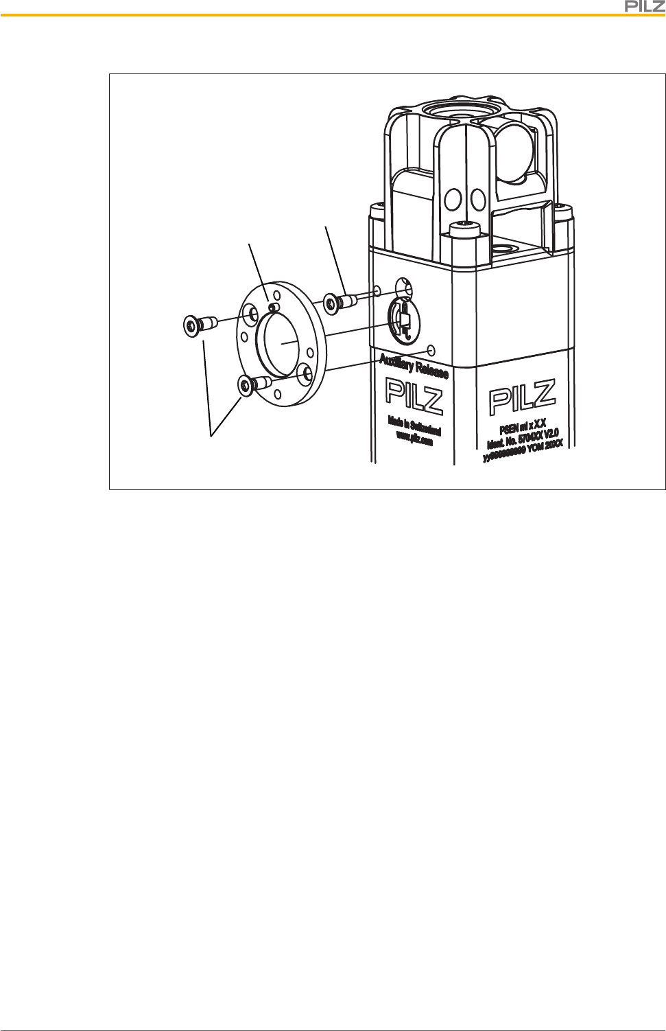
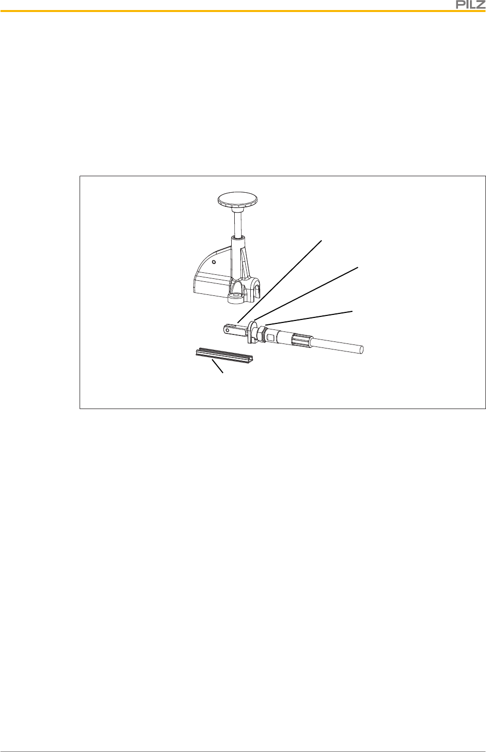
4.6 Auxiliary release
The auxiliary release enables guard locking to be opened from the access side to the
danger zone.
The safety switch has auxiliary releases on three sides.
Function description
Operating Manual PSEN ml s 1.1
1004670-EN-01 20
INFORMATION
If guard locking is deactivated using the auxiliary release, there is a low sig-
nal at safety outputs 12 and 22. An error code will be issued (see under Op-
eration) and the safety switch switches to a fault condition.
[1]
[2]
Legend
[1] Auxiliary release screw Torx T10
[2] Security screw Torx T10, sealed with varnish when delivered
Mode of operation:
1. Remove the security screw [2] using a Torx T10 screwdriver.
2. Rotate the auxiliary release screw [1] half a turn anti-clockwise using a Torx T10 screw-
driver. The guard locking pin is displaced and the bolt is released.
The safety gate to the danger zone can be opened.
Function description
Operating Manual PSEN ml s 1.1
1004670-EN-01 21
4.6.1 Recommissioning
Recommission PSEN ml s 1.1
1. Rotate the auxiliary release screw [1] (see Figure [ 20]) half a turn clockwise using a
Torx T10 screwdriver.
2. Re-insert the security screw [2] (see Figure [ 20]) using a Torx T10 screwdriver.
3. Seal the security screw with varnish.
4. Switch the voltage off and then on again.
5. Carry out a function test on the safety switch and actuator. The safety function may only
be checked by qualified personnel.
INFORMATION
If the auxiliary release screw is not turned back correctly after use, the
PSEN ml s 1.1 switches to a fault condition.
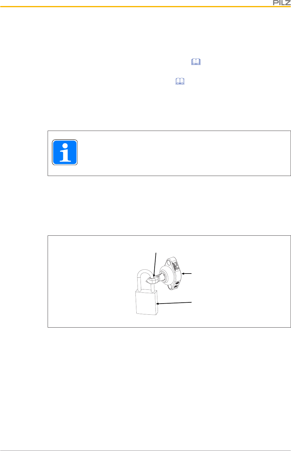
4.7 Prevent restart
To prevent the machine restarting (unintentionally) while there is someone inside the
danger zone, a padlock can be attached via the through hole on the actuator (see diagram).
As a result the actuator cannot engage with the safety switch, guard locking is not activated
and the machine is prevented from starting.
[1]
[2]
[3]
Legend
[1] Through hole on the actuator for attaching a padlock
[2] Padlock
[3] Actuator
If the actuator is to blocked using several locks in parallel, a multiple lock can be used (e.g.
Brady – Lockout device, article no.852439).
Function description
Operating Manual PSEN ml s 1.1
1004670-EN-01 22
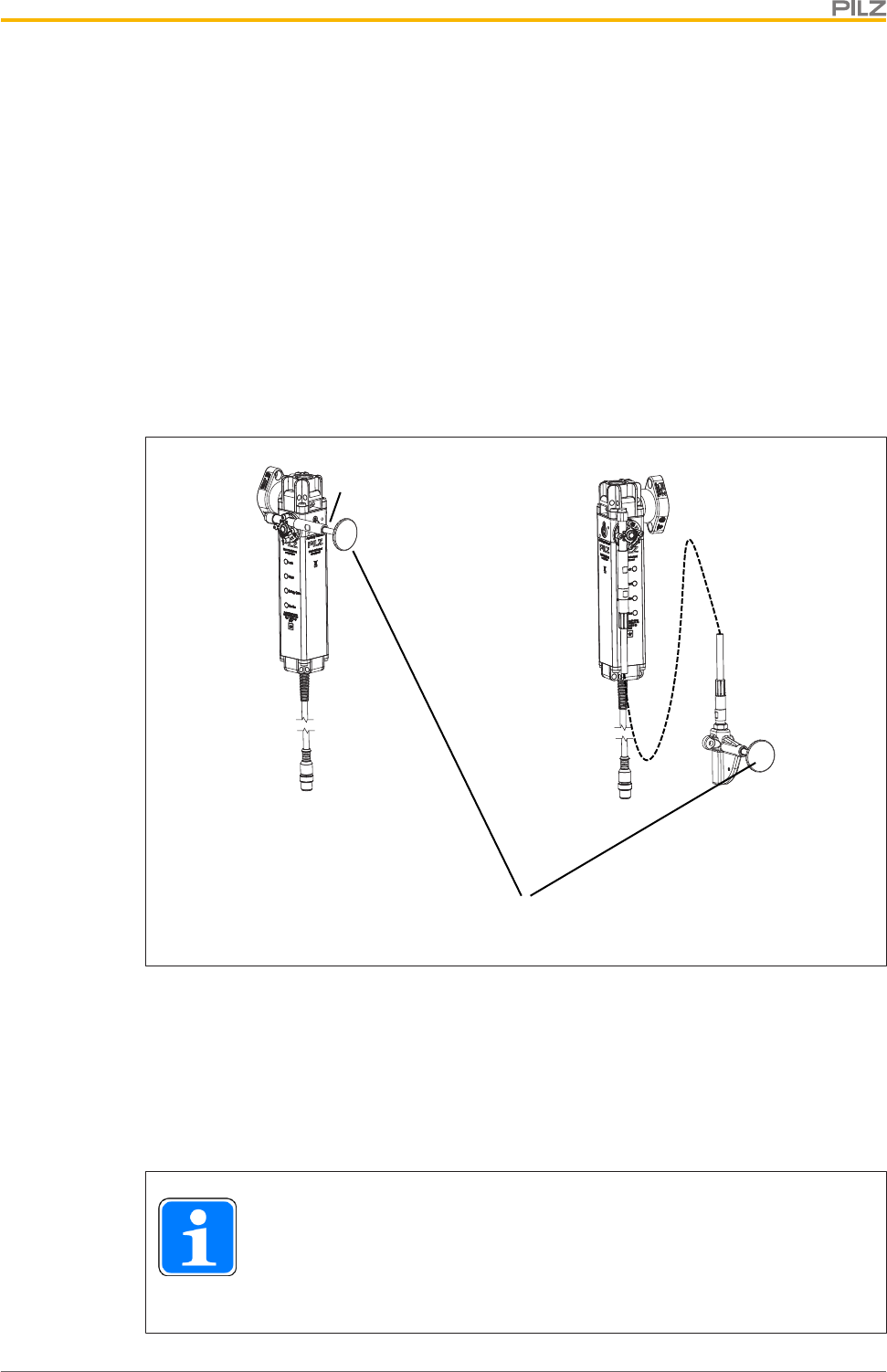
4.8 Escape release
Distinction between escape release and emergency release
}The emergency release enables the manual release of the guard locking without aids
from outside the hazardous area.
}The emergency release enables the manual release of the guard locking without aids
from within the hazardous area and it corresponds to an escape release in accordance
with ENISO14119.
If the escape release accessory (stationary or external) is installed within the hazardous
area, the accessory can be used as an escape release in accordance with ENISO14119.
If the escape release accessory (stationary or external) is installed outside the hazardous
area, the accessory can be used as an escape release in accordance with ENISO14119.
[1]
[2]
[3]
[4]
[5]
Legend
[1] Escape release stationary
[2] Escape release externally
[3] Tension pressure cables in lengths of 1.50m to 4m
[4] Button of the escape release pin
[5] Escape release pin
INFORMATION
If guard locking is deactivated using the auxiliary release, there is a low sig-
nal at safety outputs 12 and 22. An error code will be issued (see under Op-
eration) and the safety switch switches to a fault condition.

Function description
Operating Manual PSEN ml s 1.1
1004670-EN-01 23
Mode of operation
If in the hazardous area the button of the escape release pin [4] is pressed towards the
safety gate, the escape release impacts directly on the auxiliary release of the safety switch
and the auxiliary release unlocks the safety gate. The safety gate can be opened immedi-
ately, enabling the operator to leave the danger zone.
There is a low signal at safety outputs 12 and 22 if the escape release was operated.
Scope
}Scope of supply stationary escape release
– 1 escape release stationary
– 1 adapter disk
– 2 screws for adapter disk
– 4 screws for installation on the adapter disk
}Scope of supply external escape release
– 1 escape release external with installed push/pull cables (see Order reference:
Accessories [ 71])
– 1 adapter disk
– 2 screws for adapter disk
– 4 screws for installation on the adapter disk
4.8.1 Recommissioning
1. Pull back the button of the escape release pin.
2. Switch the voltage off and then on again.
3. Carry out a function test using the escape release. The safety function may only be
checked by qualified personnel.
Wiring
Operating Manual PSEN ml s 1.1
1004670-EN-01 24
5 Wiring
5.1 Important information
}Hand-tighten the connector.
}Information given in the Technical details [ 65] must be followed.
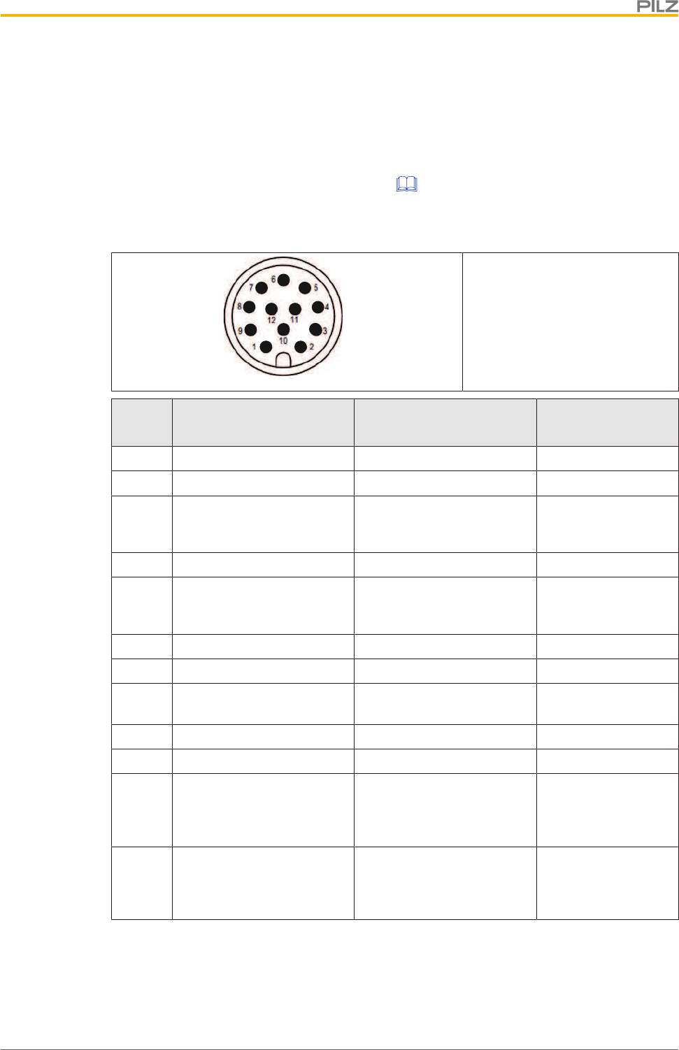
5.2 Pin assignment, connector and cable
12-pin M12 male connector
PIN Function Terminal designation
Cable colour (Pilz
cable)
1 +24 V UB A1 Brown
2 0 V UB A2 Blue
3 Operation of solenoid to
open and close guard lock-
ing (channel 2)
S41 White
4 Safety output channel 1 12 Green
5 Operation of solenoid to
open and close guard lock-
ing (channel 1)
S31 Pink
6 Safety output channel 2 22 Yellow
7 Safety input channel 1 S11 Black
8 Signal output/diagnostic
output
Y32 Grey
9 Diagnostics input Y1 Red
10 Safety input channel 2 S21 Purple
11 Operation of solenoid of the
next safety switch in the
series connection (channel
1)
32 Grey-pink
12 Operation of solenoid of the
next safety switch in the
series connection (channel
2)
42 Red-blue
Wiring
Operating Manual PSEN ml s 1.1
1004670-EN-01 25
NOTICE
The colour marking for the connection lead only applies for the cable that
Pilz supplies as an accessory
5.3 EMC requirements
}Ensure the wiring and EMC requirements of EN 60204-1 are met.
}UL requirement: The supply voltage to the safety switch must be protected with a quick-
acting fuse (see Technical details [ 65]).
}The inputs and outputs of the safety switch must have a protective separation to
voltages over 60 V AC.
}The power supply must meet the regulations for extra low voltages with protective sep-
aration (SELV, PELV) in accordance with EN60204-1.
INFORMATION
Only use safety relays with a 24 VDC supply voltage. Safety relays with a
wide-range power supply or in AC device versions have internal potential
isolation and are not suitable as evaluation devices.
Connection to control systems and evaluation devices
Operating Manual PSEN ml s 1.1
1004670-EN-01 26
6 Connection to control systems and evaluation
devices
6.1 Important information
Make sure that the selected evaluation device has the following properties:
}2-channel with feasibility monitoring
Both OSSDs must change switch state synchronously. In particular, the evaluation
device must monitor that the state of both OSSDs was "Gate unlocked" before both re-
turn to the "Gate locked" state and vice-versa.
}OSSD signals are evaluated through 2 channels
}The state of the OSSDs must be tested before and after safety inputs S31 and S41 are
activated (solenoid operation) (see Timing diagram [ 17])
WARNING!
Potential loss of safety function due to failure to test for a safe condition
Depending on the application, serious injury or death may result.
– Use an evaluation device/safety system to test whether the plant is in
a safe condition.
– Do not operate the solenoid of the PSEN ml s 1.1 via S31/S41 unless
the plant is in a safe condition.
}The use of Safety Device Diagnostics is described in the System Description "Safety
Device Diagnostics".
6.2 Minimum requirements for activation of guard locking
Use in PL e (Cat. 4) applications
}Safety inputs S31 and S41 (solenoid operation) have 2-channel operation via safe out-
puts, which are suitable for PL e (Cat. 4) applications
}2-channel operation for safety inputs S31 and S41 (solenoid operation), each with 0.5A
}2-channel processing of safety outputs
}Monitoring of shorts across signal cables through activation of guard locking
Connection to control systems and evaluation devices
Operating Manual PSEN ml s 1.1
1004670-EN-01 27
PSEN ml
Actuator
A1
A2
22
Y32
S31 S41
12
PSEN ml
Sensor
24 V
0 V
Lock/Unlock Request 2
Lock/Unlock Request 1
S11 S21
Programmable safety system
Activation of guard locking
Use in PL d (Cat. 3) applications
}2-channel operation for safety inputs S31 and S41 (solenoid operation) via relay out-
puts
}2-channel operation for safety inputs S31 and S41 (solenoid operation), each with 0.5A
}2-channel processing of safety outputs
}Exclusion of shorts across signal cables through appropriate measures (e.g. protected
cable layout, see EN ISO 13849-2)
PSEN ml
Actuator 22
Y32
S31 S41
12
PSEN ml
Sensor
Lock/Unlock Request 2
Lock/Unlock Request 1
24 V
[1]
A1
A2
24 V
0 V
S11 S21
Programmable safety system
Activation of guard locking
Legend
[1] Protected cable layout
Connection to control systems and evaluation devices
Operating Manual PSEN ml s 1.1
1004670-EN-01 28
Use in PL d (Cat. 2) applications
}1-channel operation for safety inputs S31 and S41 (solenoid operation)
}2-channel processing of safety outputs
}1-channel operation for interconnected safety inputs S31 and S41 (solenoid operation),
with 1A
Programmable safety system
Activation of guard locking
PSEN ml
Actuator 22
Y32
S31 S41
12
PSEN ml
Sensor
Lock/Unlock Request
A1
A2
24 V
0 V
S11 S21
6.3 Single connection
24 V 0 V
A1
A2
12 22
I2 (FS)
I1 (FS)
FS: Failsafe
A1
A2
S31 S41
Y32
O2 (FS)
O1 (FS)
I1
S11 S21
Actuator Safety switch
Programmable safety system
Activation of guard locking
Connection to control systems and evaluation devices
Operating Manual PSEN ml s 1.1
1004670-EN-01 29
6.4 Series connection
CAUTION!
Extension of delay-on de-energisation
When several (n) devices are connected in series, the delay-on de-ener-
gisation time adds with the number of interconnected safety switches.
The max. delay-on de-energisation is made up of the
risk time (see Technical details [ 65])
+ (n-1) x max. delay-on de-energisation of the inputs
+ max. delay-on de-energisation of the evaluation device
The safety switches PSEN ml s 1.1 are suitable for series connection with max. 16 safety
switches.
In practice, the maximum possible number will be limited by the following parameters,
among others:
}The required SIL level (e.g. SIL CL 3),
}the required performance level (e.g. PL e (Cat. 4)),
}the maximum delay or risk time permitted by the application,
}Cable length (see notes on cable lengths),
}Height of supply voltage.
Ensure there is sufficient supply voltage, taking inrush currents and fusing into considera-
tion.
Notes on cable lengths
}Determine the values under the following conditions:
Room temperature (25°C), conductor cross section 0.25mm2, output load per output
(12,22,Y32) each ≤10mA
[1]
L1
[2] [2] [2]
L2 L3 L4 L5 L6
[2] [2] [2]
Legend
[1] Safety control system
[2] Safety switch PSEN ml
Connection to control systems and evaluation devices
Operating Manual PSEN ml s 1.1
1004670-EN-01 30
Examples for cable lengths
}Operating voltage at the safety control system ≥ 20.4 V
Number of safety
switches L1 L2 L3 L4 L5 L6
Overall
length
1 50 m 50 m
2 30 m 20 m 50 m
3 20 m 10 m 10 m 40 m
4 20 m 5 m 5 m 5 m 35 m
5 10 m 5 m 5 m 5 m 5 m 30 m
6 5 m 5 m 5 m 5 m 5 m 5 m 30 m
}Operating voltage at the safety control system ≥ 24 V
Number of safety
switches L1 L2 L3 L4 L5 L6
Overall
length
1 120 m 120 m
2 60 m 60 m 120 m
3 50 m 50 m 20 m 120 m
4 50 m 30 m 20 m 20 m 120 m
5 50 m 20 m 20 m 20 m 10 m 120 m
6 20 m 20 m 20 m 20 m 20 m 20 m 120 m
}Operating voltage at the safety control system ≥ 28.8 V
Number of safety
switches L1 L2 L3 L4 L5 L6
Overall
length
1 180 m 180 m
2 130 m 50 m 180 m
3 80 m 50 m 50 m 180 m
4 50 m 50 m 50 m 30 m 180 m
5 50 m 50 m 30 m 30 m 20 m 180 m
6 50 m 50 m 20 m 20 m 20 m 20 m 180 m
Connection to control systems and evaluation devices
Operating Manual PSEN ml s 1.1
1004670-EN-01 31
24 V 0 V
A1
A2
12 22
S21S11
FS: Failsafe
A1
A2
S31 S41
Y32
4232
12 22
12 22
A1
A2
A1
A2
Rx Tx
S21S11
I2I1
S21S1132 42
S31 S41
4232
S31 S41
O2O1
Y1
Y32
Y1
Y32
Y1
Actuator Safety switch
Fieldbus module
Safety control system
Safety switch
Safety switch
Actuator
Actuator
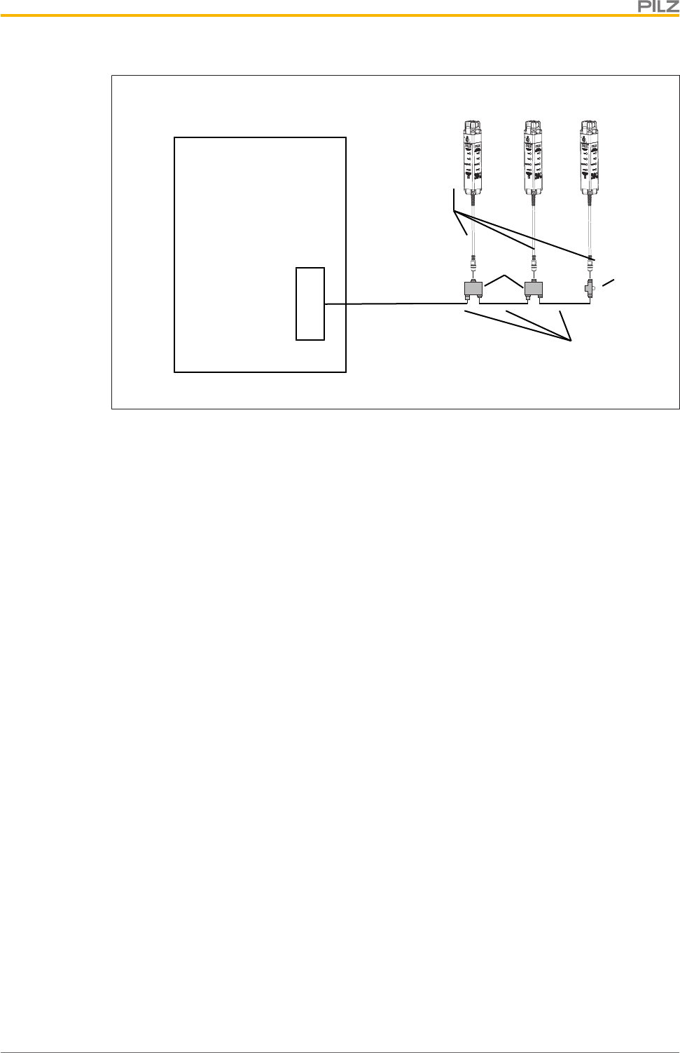
For connecting the safety switch PSEN ml s 1.1 in a series connection there are the follow-
ing options:
}Wiring with the safety control system via PSEN ml Y junction
Connection to control systems and evaluation devices
Operating Manual PSEN ml s 1.1
1004670-EN-01 32
3 x PSEN ml s
X1 X2
X3
X1 X2
X3
X1
X2
Safety control system
8-core
12-core
[1] [2]
Legend
[1] PSEN ml Y junction M12
[2] PSEN ml end adapter
}When establishing the series connections with connection to the safety control system,
use the following adapters:
– PSEN ml Y junction M12
– PSEN ml end adapter
}Connection in the control cabinet at the terminal block
– Connect the 12-core cables of the safety switch to the terminal block of the control
cabinet.
6.5 Connection to Pilz evaluation devices
The safety switch PSEN ml s 1.1 can be connected to Pilz evaluation devices, for example.
Suitable Pilz evaluation devices are, for example:
}PNOZmulti for safety gate monitoring
Configure the switch in the PNOZmulti Configurator with switch type 3.
}PSS for safety gate monitoring with standard function block SB064, SB066 or
FS_SafetyGate
}PSSuniversal PLC for safety gate monitoring with function block FS_SafetyGate
The correct connection to the respective evaluation device is described in the operating
manual for the evaluation device. Make sure that the connection is made in accordance
with the specifications in the operating manual for the selected evaluation device.
Connection to control systems and evaluation devices
Operating Manual PSEN ml s 1.1
1004670-EN-01 33
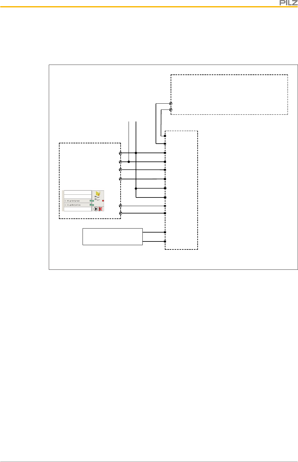
Connection to PNOZmulti is illustrated by way of example.
6.5.1 Connection example with PNOZmulti and Safety Device Diagnostics
A1
A2
I0
I1
A1
A2
Y32
Y1
12
22
1
2
3
4
5
6
7
8
PNOZmulti
PSEN ml
0 V
24 V
S31
S41
O2 (FS)
O1 (FS)
Rx
1
6S11
S21
Tx
32
42
11
12
Activation of guard locking via SDD ES module
following PSEN ml

Installation
Operating Manual PSEN ml s 1.1
1004670-EN-01 35
8 Installation
8.1 Important information
INFORMATION
Refer to the guidelines for designing guards and integrating interlocks with
guard locking in ENISO14120.
NOTICE
Install the safety switch and actuator so that the possibilities of defeat are
reduced to a minimum (see guidelines for reducing the possibilities for de-
feating interlocking devices in EN ISO 14119).
NOTICE
Install safety switch and actuator so that it is not possible to reach through
with hand or finger.
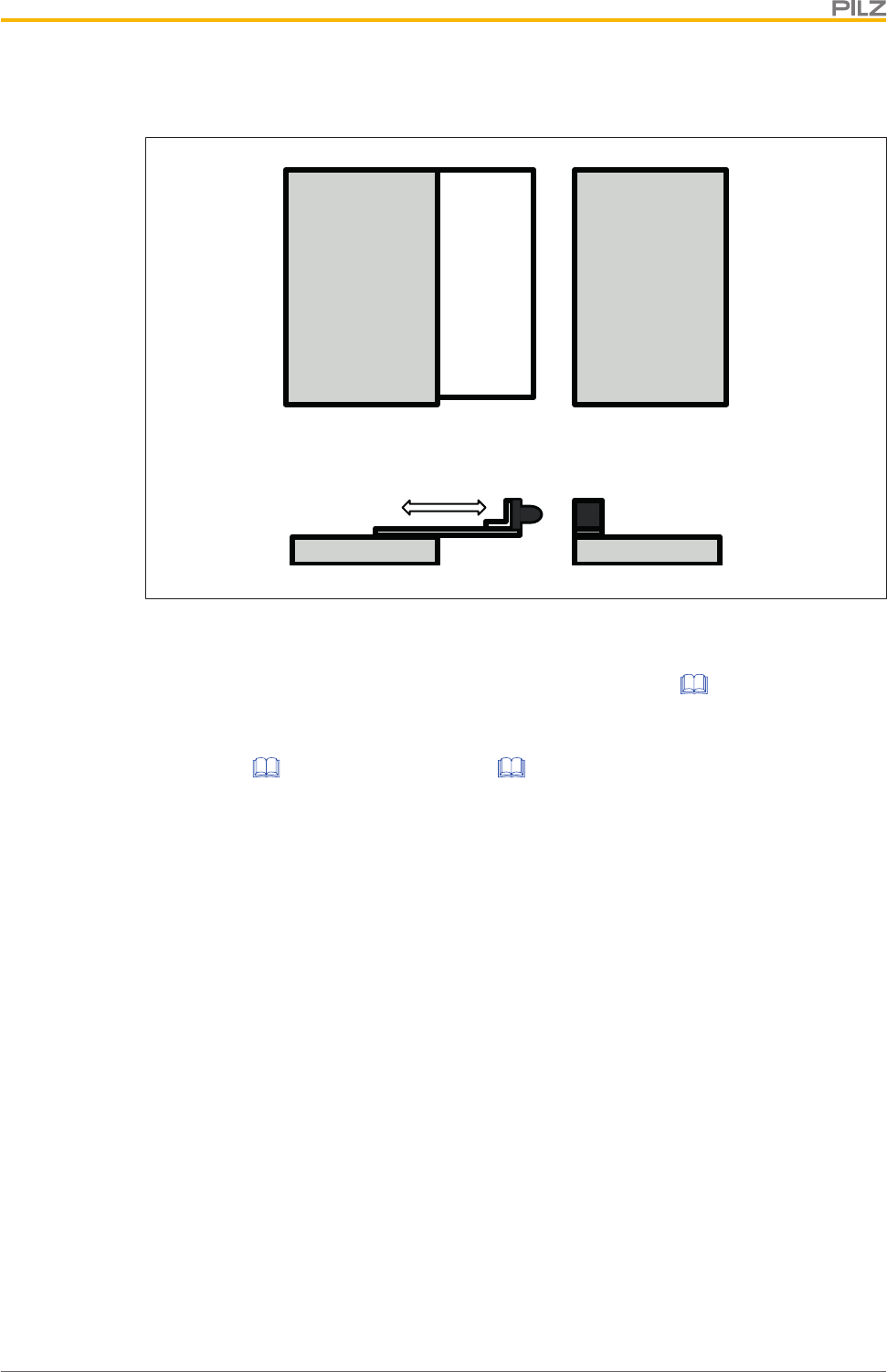
}The safety switch and actuator should be installed opposite each other in parallel.
}Make sure that the actuator makes complete contact with the mounting surface.
}Make sure that the at least one of the auxiliary release/escape releases can be oper-
ated after installation.
}For a minimum screw depth of 6 mm, M5 screws with resistance class 8.8 should be
used to attach the safety switch and actuator.
}Torque setting: Please note the information provided under Technical details [ 65].
}Use non-removable flat head locking screws to attach the safety switch and actuator
(e.g. cheese-head or pan head screws) or rivets.
}Use the same type of screw to attach the safety switch and actuator.
}Installation of the safety switch and actuator must be concealed.
}Prevent self-loosening of the fastening elements on the safety switch and actuator,
– On the safety switch: through torque (see Technical details [ 65])
– On the actuator: through torque (see Technical details [ 65]) and bonded screw
retention
}Make sure that the actuator does not present a risk.
}The mounting surfaces for safety switches and actuators can have a max. unevenness
of 0.5 mm.
}Prevent the safety switch and actuator being exposed to heavy shock or vibration.
}The fastening of safety switch and actuator has to be sufficiently stable to ensure the
proper operation of the safety switch and the actuator.
Installation
Operating Manual PSEN ml s 1.1
1004670-EN-01 36
8.2 Tapped hole
}To fix the safety switch at the three possible mounting positions, there are 3 drill holes
on 3 sides.
As a result, the safety switch can be installed on the frames of left and right hinged slid-
ing gates and swing gates. If necessary use a Mounting plate [ 44] or Mounting
bracket [ 44] (see Order reference: Accessories [ 71]).
Different holding forces arise, based on the installation.
–Fixing screws in parallel to actuator [ 38]:
Holding forceFZh=7.500 N,
Holding forceF1maxin accordance withENISO14119=15.000 N
–Fixing screws side-on to actuator [ 38]:
Holding forceFZh=5.000 N,
Holding forceF1maxin accordance withENISO14119=10.000 N
INFORMATION
Please note that the stated holding forces only apply when installed without
a mounting bracket. The holding forces when installed with a mounting
bracket can be found in the table "Technical details for mounting
bracket [ 70]".
The tapped holes must have a depth of at least 6 mm.
Installation of safety switch Tapped hole
Fixing screws in parallel/side-on to actuator,
no mounting plate
Tapped holes for four M5 screws on the
mounting surface.
Fixing screws in parallel/side-on to actuator,
with mounting plate
Tapped holes for two M8 screws on the
mounting surface, for attaching the mount-
ing plate.
Installation
Operating Manual PSEN ml s 1.1
1004670-EN-01 37
31
19,2193,54,5
Fixing screws in parallel/side-on to actu-
ator, no mounting plate
Provide the mounting surface with tapped
holes as indicated.
ø 8,5
Fixing screws in parallel/side-on to actu-
ator, with mounting plate
Provide the mounting surface with tapped
holes as indicated.
ø 5,35
ø 10
48
Actuator, no mounting bracket
Provide the mounting surface with tapped
holes for two M5 screws (see diagram).
Installation
Operating Manual PSEN ml s 1.1
1004670-EN-01 38
ø 6,5
Actuator, with mounting bracket
Provide the mounting surface with tapped
holes for two M6 screws (see Dimensions).
(Diagram: order no. 570 492 as example)
8.3 Install fixing screws in parallel to actuator
Use four M5 screws to attach the switch to the mounting surface.
}Torque setting: Please note the information provided under Technical details [ 65].
X
Y [3]
[3]
[1] [2]
Fig.: Fixing screws of the safety switch in parallel to actuator
Legend
[1] Safety switch
[2] Actuator
[3] Fixing screws of the safety switch in parallel to actuator
8.4 Install fixing screws side-on to actuator
[1]
[2]
[1] Front of safety switch
[2] Actuator
Installation
Operating Manual PSEN ml s 1.1
1004670-EN-01 39
[1] [1]
[1] [1]
Use four screws [1] to fix the
safety switch to the mount-
ing surface.
Fully tighten the four screws
[1] on the safety switch.
Torque setting: Please note
the information provided un-
der Technical
details [ 65].
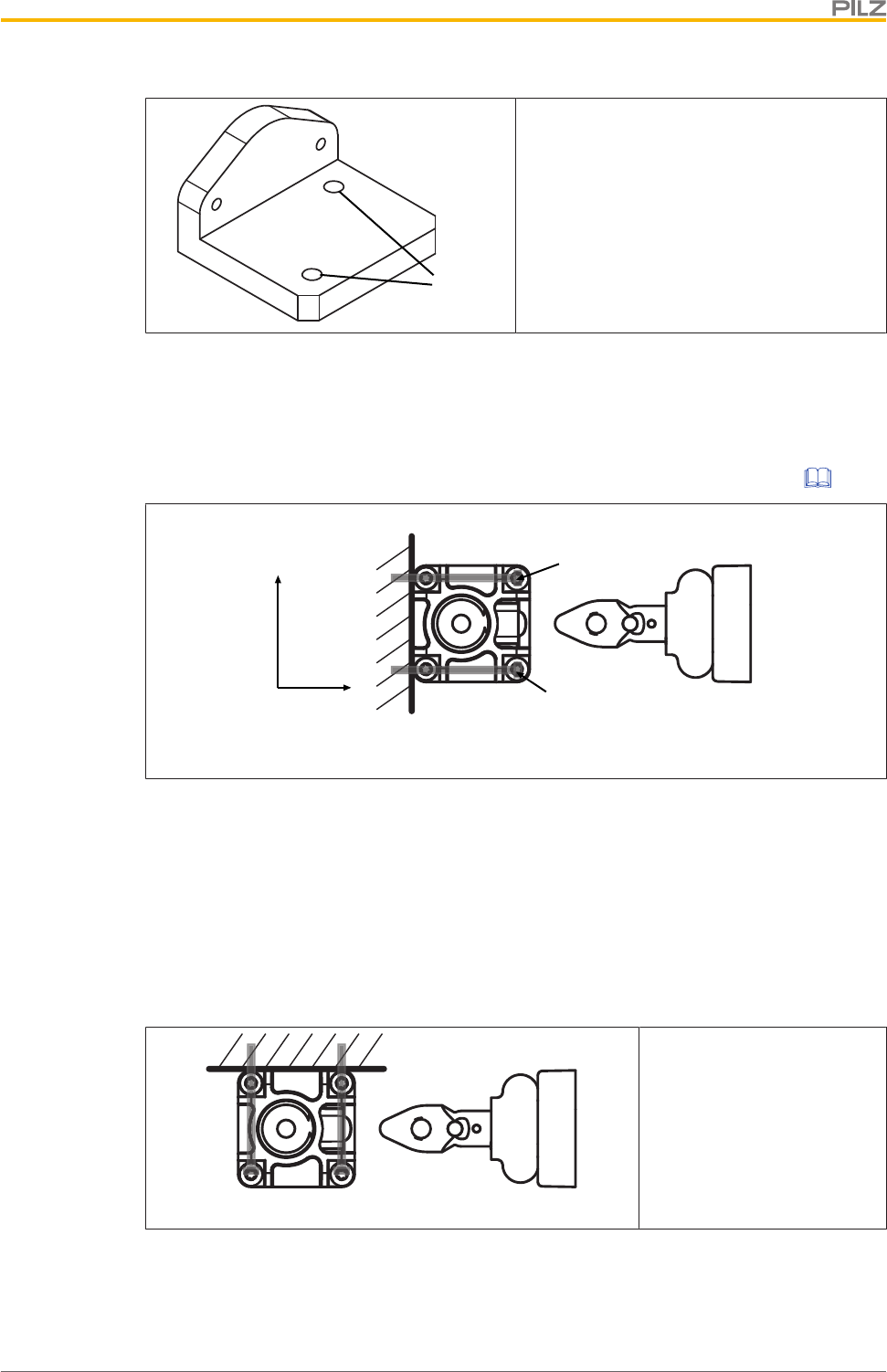
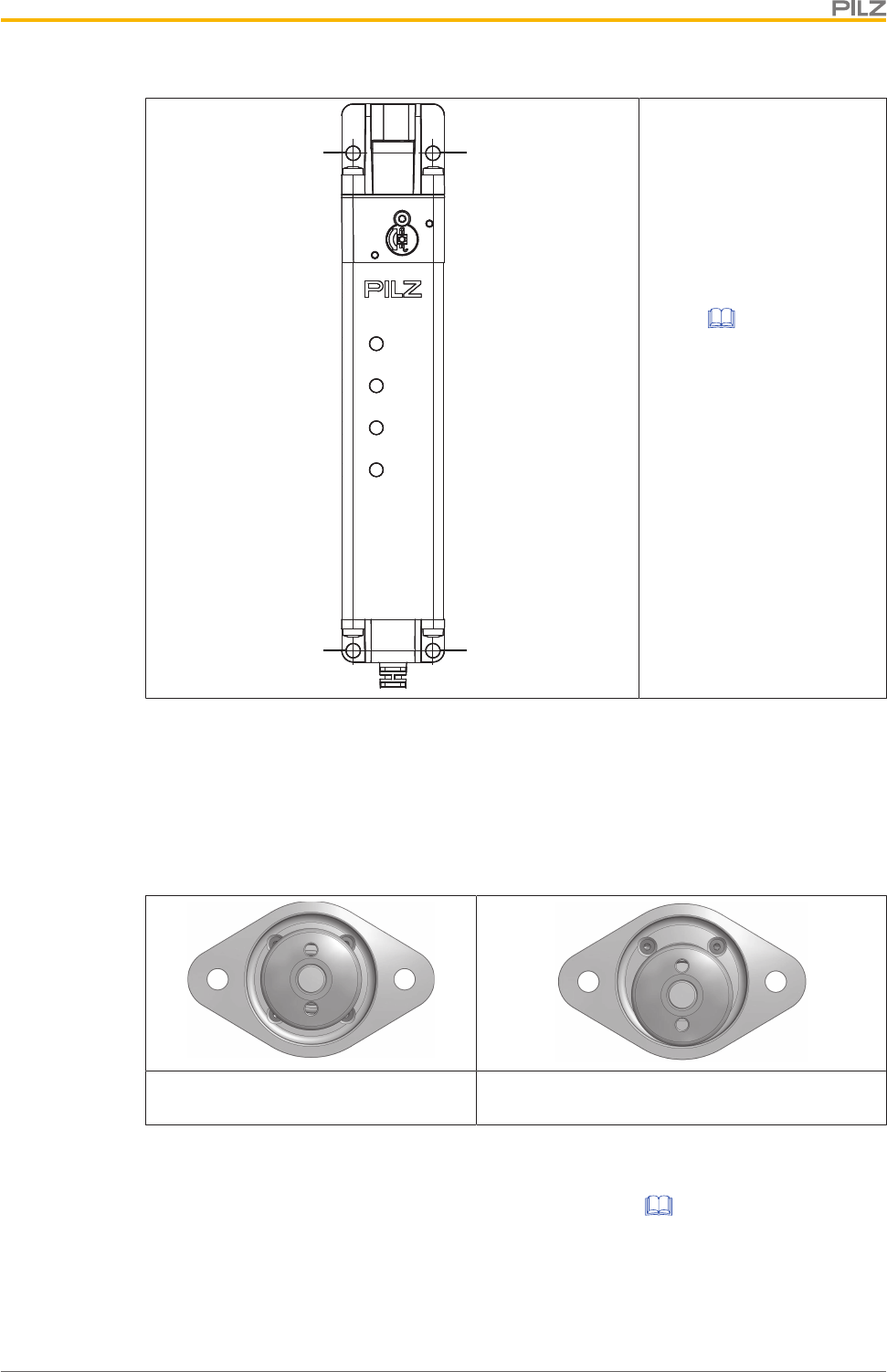
8.5 Centre the bolt in the actuator housing
The bolt must be centred in the actuator housing in order to maintain the distances on set-
tling gates.
Centre the bolt in the actuator housing (see diagram).
Bolt centred within the actuator hous-
ing
Bolt not centred within the actuator housing
8.6 Rotate the bolt in the actuator housing 90°
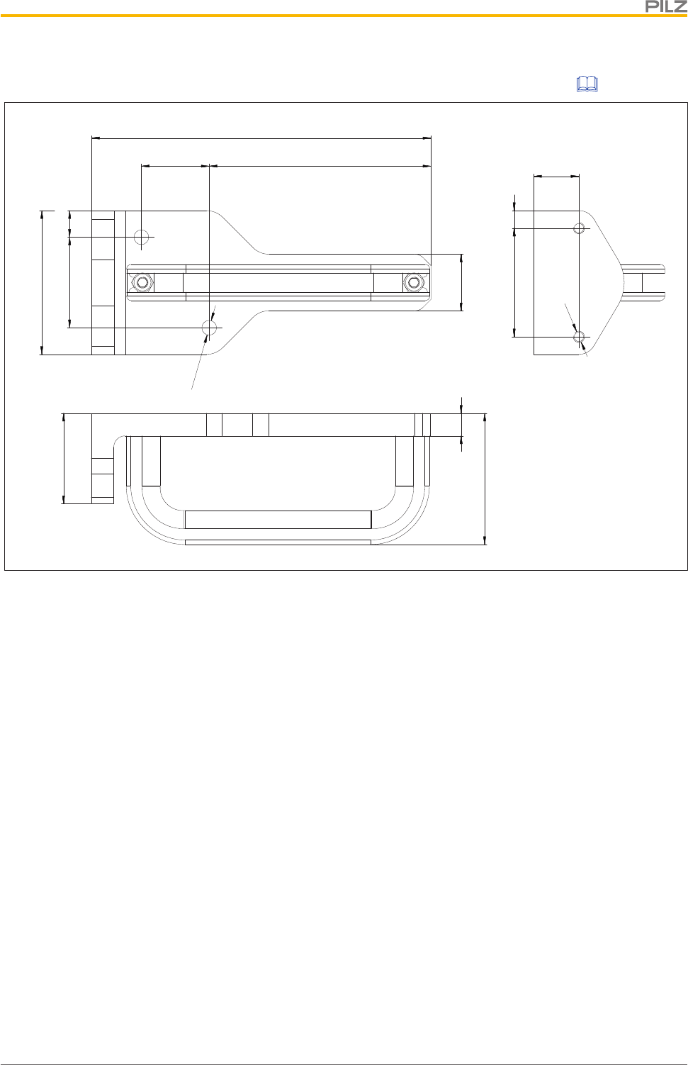
The actuator can be installed vertically on a gate (see Figure [ 11]). To install the actu-
ator horizontally, the bolt can be rotated 90° in the actuator housing prior to installation.
1. On the housing skin [3] in the actuator housing, press down the spring plate [1] on both
sides of the bolt and keep the plate held down.
2. Rotate the bolt in the housing skin by 90° in the required direction ([2]).
Installation
Operating Manual PSEN ml s 1.1
1004670-EN-01 41
8.7 Installation on sliding gate
[1]
[2]
Legend
[1] Safety switch, installed on gate frame
[2] Actuator with mounting bracket (available as Accessory [ 71]), installed on
sliding gate
1. Install the safety switch with the fixing screws of the safety switch in parallel to the
actuator [ 38] or side-on to actuator [ 38] on the gate frame.
2. Use two M5 screws to fix the actuator to the gate.
Installation
Operating Manual PSEN ml s 1.1
1004670-EN-01 42
8.8 Installation on swing gate
[1]
[2]
[2]
Fig.: Swing gate with internal and external hinge
Legend
[1] Safety switch on gate frame
[2] Actuator, installed on swing gate
1. Install the safety switch with the fixing screws of the safety switch in parallel to the
actuator [ 38] or side-on to actuator [ 38] on the gate frame.
2. Use two M5 screws to fix the actuator to the gate.
The actuator should engage smoothly into the safety switch.
Install the safety switch horizontally at a swing gate
Please note:
Depending on the installation boundary conditions, a larger gate radius may be required
(see diagram).
Please contact Pilz when smaller gate radiuses are required.
Installation
Operating Manual PSEN ml s 1.1
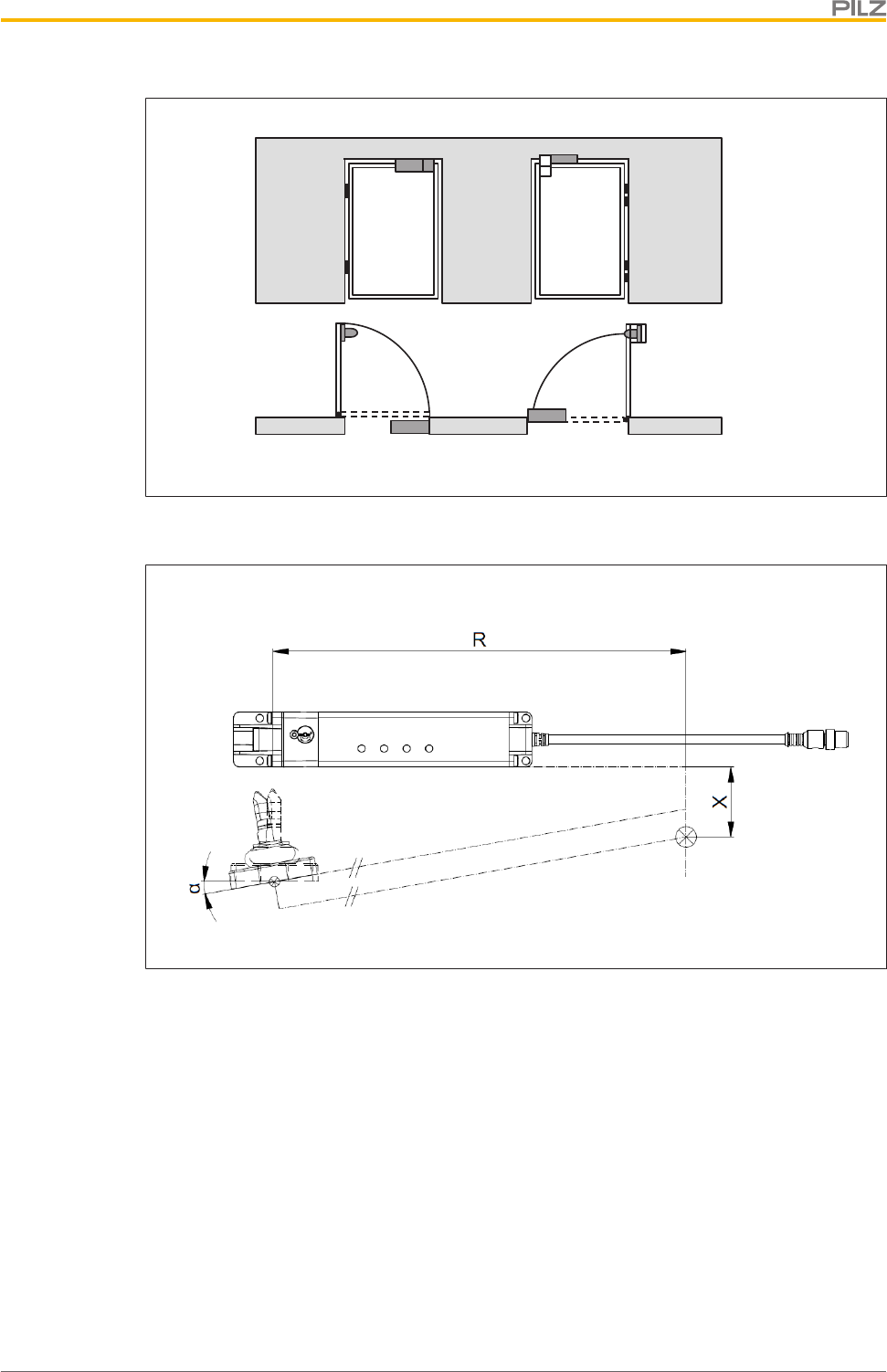
1004670-EN-01 43
Make sure that a slight shift of the rotation point of the door is maintained when installing
the actuator.
Legend
R The distance of the upper part of the safety switch from the rotation point of the
door
X Parallel shift of the actuator
α Tilt angle when installing the actuator
}Tilt the actuator during installation by 10° in the following situations:
– 50 mm < X < 75 mm and R < 600 mm
– X < 50 mm and R < 500 mm
Installation
Operating Manual PSEN ml s 1.1
1004670-EN-01 44
8.9 Installation with mounting bracket
1. Use two M6 screws to fix the mounting bracket to the gate. The position of the drill
holes can be taken from the section entitled Dimensions.
2. Use two M5 screws to fix the actuator to the mounting bracket.
Fig.: Actuator, installed on mounting bracket
8.10 Installation with mounting plate
1. Attach the mounting plate to the swing gate/sliding gate.
2. Use four M5 screws to fix the safety switch [ 38] to the mounting plate.
Fig.: Safety switch, installed on mounting plate
Installation
Operating Manual PSEN ml s 1.1
1004670-EN-01 45
8.11 Installing the escape release
8.11.1 Important information
WARNING!
Loss of safety function due to the incorrect installation of the escape re-
lease!
If the button of the escape release pin is accessible from the outside, the
guard locking device can be released from the outside and the safety gates
opened, although the hazardous machine is switched on.
Depending on the application, serious injury or death may result.
The escape release should be installed so that it is only accessible from in-
side the danger zone.
}The button of the escape release pin must be impossible to reach from a position out-
side the protected area.
}Make sure that the escape release cannot be operated unintentionally.
}Prevent the effect of transverse forces on the escape release.
}Secure the screw joints with a with a threadlocker.
}Ensure that the button of the escape release pin is clearly visible and that is it not
covered.
}Make sure that the min. bending radius of the push/pull cable of60mm is maintained
when using the external escape release.
}Make sure that the button of the escape release pin does not present a risk.
}The mounting surface has to completely cover the bottom of the escape release hous-
ing. The bottom of the escape release housing must not be accessible after installation.
Installation
Operating Manual PSEN ml s 1.1
1004670-EN-01 46
8.11.2 Installation positions for escape release
The stationary escape release can be installed on the three auxiliary releases in three dif-
ferent directions each.
[1] [2]
Legend
[1] Installation options at the sides
[2] Installation options at the back
Installation
Operating Manual PSEN ml s 1.1
1004670-EN-01 47
The external escape release can be installed on the three auxiliary releases in four different
directions each. The push/pull cable can be led out on different sides.
[1] [2]
Legend
[1] Installation options at the sides
[2] Installation options at the back
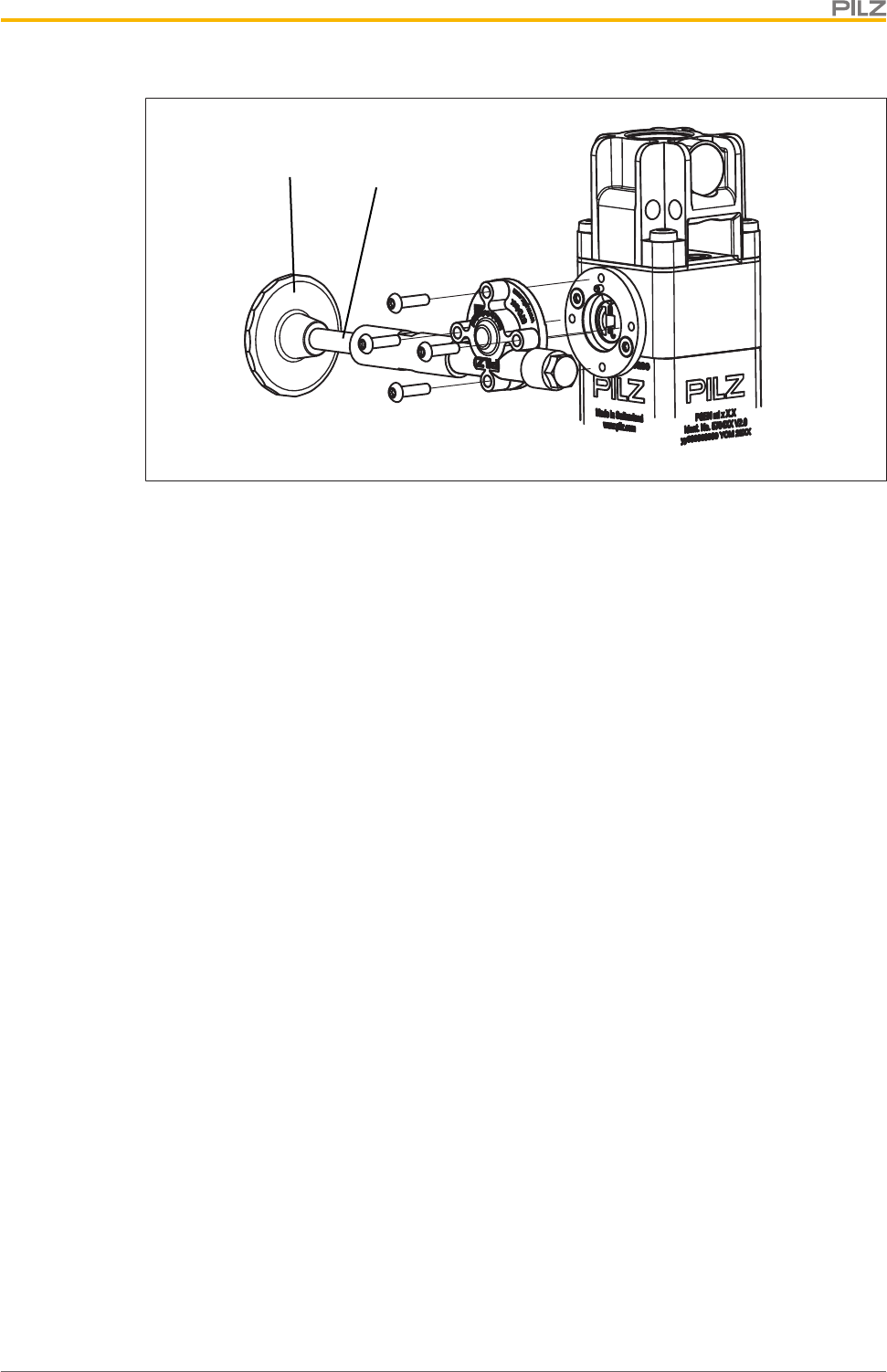
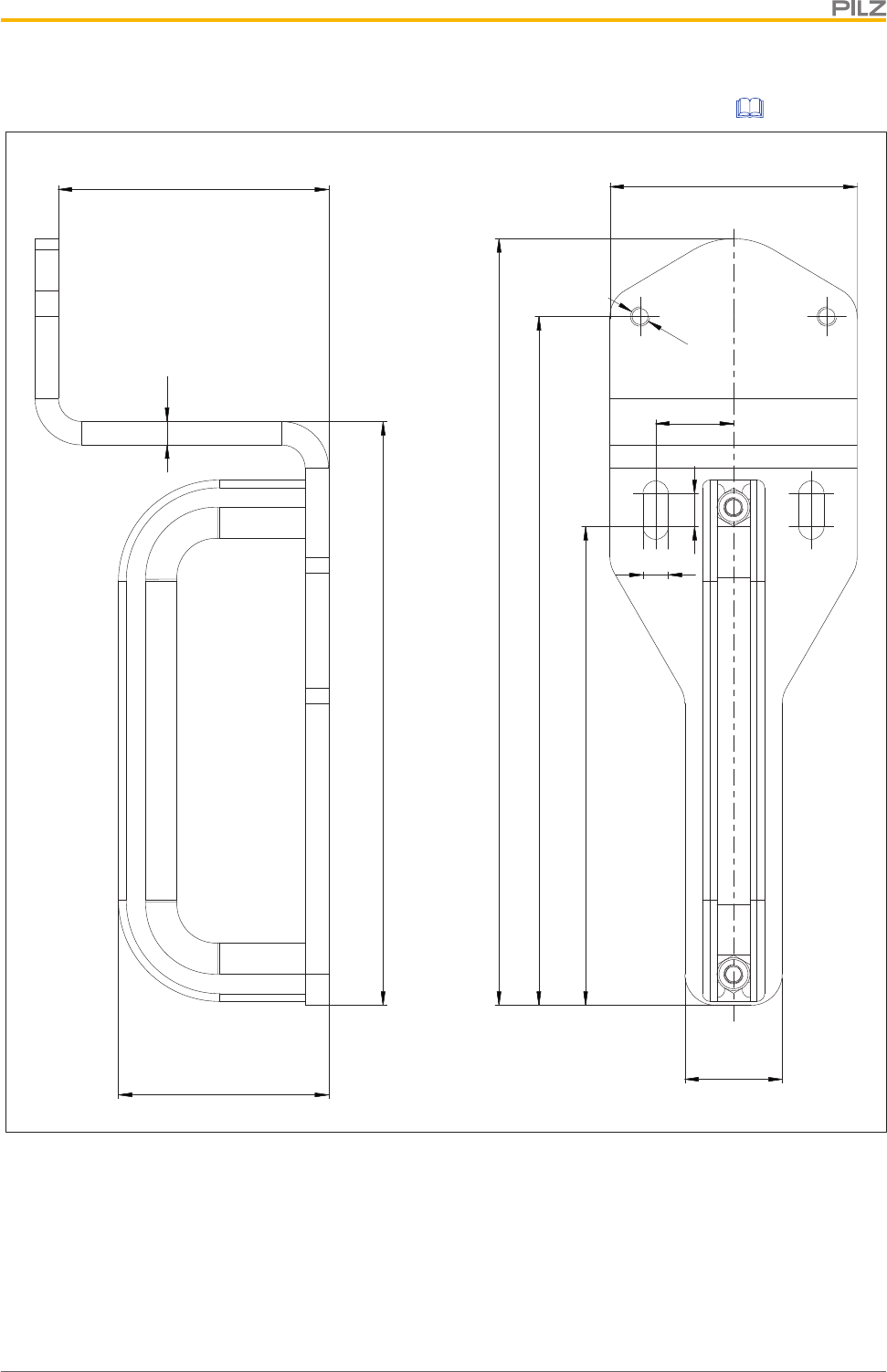
8.11.3 Installation stationary escape release
1. Remove the security screw [1] using a Torx T10 screwdriver T10.
2. Screw the adapter disk of the escape release with the two hexagon sockets M3x8[3]
on the safety switch with 1,2 - 1,5 Nm (see diagram). Make sure that the pin of the ad-
apter disk [2] is at the place where the security screw of the auxiliary release [1] used to
be.
Installation
Operating Manual PSEN ml s 1.1
1004670-EN-01 48
[1]
[2]
[3]
Legend
[1] Security screw of the auxiliary release
[2] Pin in the adapter disk
[3] Hexagon sockets M3x8
3. Screw the escape release with the 4 raised head screws M3x12 to the adapter disk with
1,2 - 1,5 Nm (see diagram).
}The button of the escape release pin can be removed for the installation (e.g. when the
escape release pin is to be run through a wall). The button of the escape release pin
must be secured again with a threadlocker and hand-tightened after escape release in-
stallation is complete
}To bridge larger distances the escape release pin can be extended by a max. of 25mm
two times (see Order reference: Accessories [ 71]).
Installation
Operating Manual PSEN ml s 1.1
1004670-EN-01 49
[2]
[1]
Legend
[1] Button of the escape release pin
[2] Escape release pin
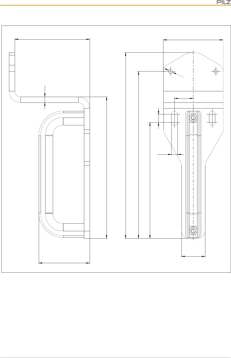
8.11.4 Installation external escape release
1. Remove the security screw [1] using a Torx T10 screwdriver T10.
2. Screw the adapter disk of the escape release with the two hexagon sockets M3x8[3]
on the safety switch with 1,2 - 1,5 Nm (see diagram). Make sure that the pin of the ad-
apter disk [2] is at the place where the security screw of the auxiliary release [1] used to
be.
Installation
Operating Manual PSEN ml s 1.1
1004670-EN-01 50
[1]
[2]
[3]
Legend
[1] Security screw of the auxiliary release
[2] Pin in the adapter disk
[3] Hexagon sockets M3x8
3. Screw the escape release with the 4 raised head screws M3x12 to the adapter disk with
1,2 - 1,5 Nm (see diagram).
Installation
Operating Manual PSEN ml s 1.1
1004670-EN-01 51
4. Screw the housing of the escape release with the screws [1] to a mounting surface with
6 - 6,5 Nm (see diagram).
}The screws of the push/pull cable [2] can be loosened to make installation easier (e.g.
when the push/pull cable is to be run through a wall). The screws must be fixed with 6 -
6,5 Nm after the escape release is installed.
[1]
[1]
[2]
Legend
[1] Screwing the escape release to the mounting area
[2] Screwing the cable
Installation
Operating Manual PSEN ml s 1.1
1004670-EN-01 52
8.11.5 Uninstalling the escape release
If the push/pull cable is to be run through a conduit pipe, the cable has to be uninstalled at
the escape release first.
Prerequisites
}The conduit pipe must have a diameter of at least 12mm.
Procedure:
1. Lift off the cover [1] (e.g. with a screwdriver with a flat blade).
[1]
[2]
[4]
[3]
Legend
[1] Cover
[2] Nut M10 x 0,75
[3] Fork head
[4] Slot nut
2. Loosen the nut [2].
3. Pull out the push/pull cable with the slot nut [4] and remove the slot nut and the nut [2]
from the cable.
4. Run the cable through the conduit pipe.
5. Push the nut [2] and the slot nut [4] over the fork head [3] back on the cable.
6. Push the cable with the fork head [3] on the fork in the escape release. The slot nut [4]
must be fitted into the nut again.
7. Tighten the nut [2] with 6 - 6,5 Nm.
8. Put the lid [1] back on.
Adjustment
Operating Manual PSEN ml s 1.1
1004670-EN-01 53
9 Adjustment
Please note:
}Safety switch and actuator must be aligned correctly
}Distances are maintained as stated in the following diagram
}Actuator is centred (see Centre bolt in actuator housing [ 39])
}Always test the function with a connected evaluation device.
}When installing an external or stationary escape release, check the function of the es-
cape release with a connected evaluation device.
[7]
[3]
[1] [2]
[6]
[8]
[4]
[2]
[1]
[5]
[2]
[1]
View from above View from the side Perspective view
[1] Safety switch
[2] Actuator
[3] Max. lateral offset +/-3,0 mm
[4] Max. vertical offset +/-3,0 mm
[5] Max. angular offset around the X axis +/-2,0 deg
[6] Max. angular offset around the Y axis +/-2,5 deg
[7] Max. angular offset around the Z axis +/-7,5 deg
[8] Max. offset in closing direction +/-2 mm
Attach safety switch and actuator
Once the safety switch and actuator are correctly aligned, the actuator's screw connection
must be tightened.
1. Tighten up one M5 screw.
2. For applications with increased safety requirements (e.g. SIL CL 2 PL d), swap the
second M5 screw for an M5 locking screw.
3. Tighten up the M5 screw or M5 locking screw.
Please note the max. torque setting stated in the Technical details [ 65].
Operation
Operating Manual PSEN ml s 1.1
1004670-EN-01 54
10 Operation
NOTICE
The safety function should be checked after initial commissioning and each
time the plant/machine is changed. The safety functions may only be
checked by qualified personnel.
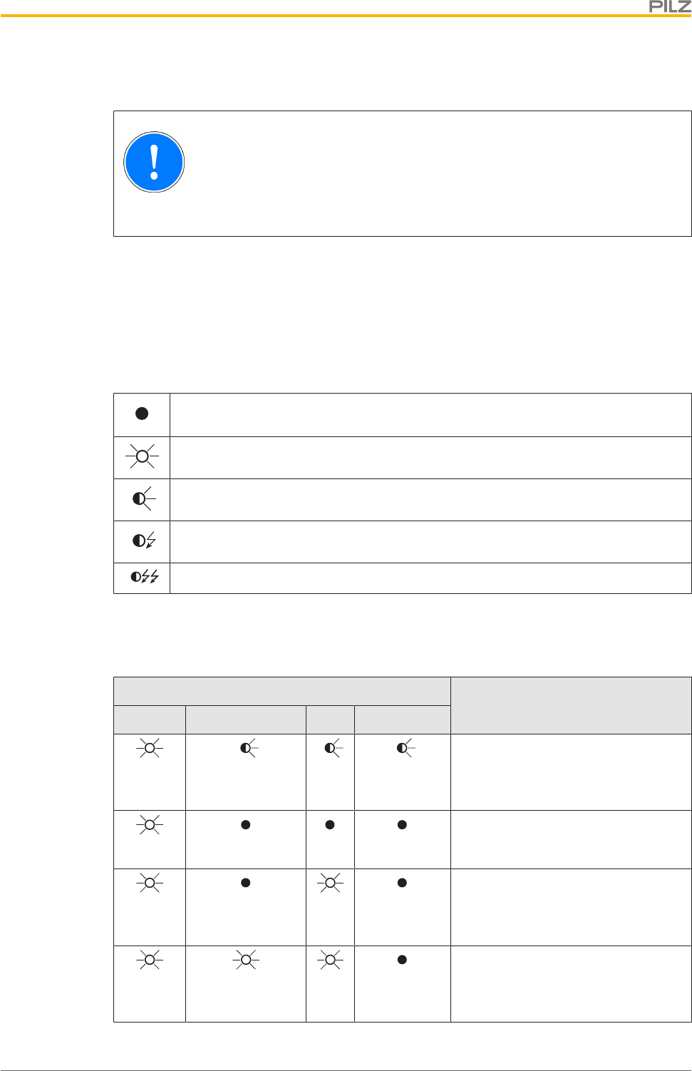
Status indicators:
}"Device" LED illuminates green: The unit is ready for operation
}"Safety Gate" LED lights up yellow: Actuator is within the response range
}"Lock" LED lights up green: Guard locking active
}"Input" LED lights independently of the status of safety inputs S11 and S21
Legend:
LED off
LED on
LED flashes (500 ms on, 500 ms off)
LED flashes quickly (50 ms on, 950 ms off)
LED flashes very quickly (25 ms on, 475 ms off)
10.1 Normal mode
LED status
Switch statusDevice Safety Gate Input Lock
Green Yellow Yel-
low
Green
PSEN ml s 1.1 is started
Green
Safety gate open, actuator not de-
tected, guard locking deactivated,
safety inputs S11 and S21 are low
Green Yel-
low
Safety gate open, actuator not de-
tected, guard locking deactivated,
safety inputs S11 and S21 are high
Green Yellow Yel-
low
Safety gate closed, actuator not de-
tected, guard locking deactivated,
safety inputs S11 and S21 are high
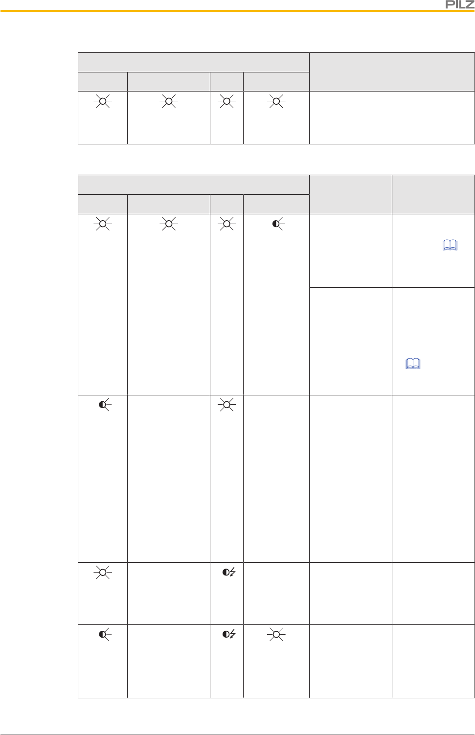
Operation
Operating Manual PSEN ml s 1.1
1004670-EN-01 55
LED status
Switch statusDevice Safety Gate Input Lock
Green Yellow Yel-
low
Green
Safety gate closed, actuator detec-
ted, guard locking activated
Warnings
LED status
Switch status
Remedy / meas-
ureDevice Safety Gate Input Lock
Green Yellow Yel-
low
Green
Safety gate
closed, actuator
detected, guard
locking cannot be
activated / deac-
tivated
Check the actu-
ator's
alignment [ 53]
to the safety
switch.
The supply
voltage to safety
inputs S31 and
S41 was
switched back on
before the auxili-
ary release
screw was turned
back.
Turn back the
auxiliary release
screw and then
switch the supply
voltage on (see
Recommissionin
g [ 21]).
Yellow
Display not defin-
itive
Yel-
low
Display not
definitive
Safety switch
active despite
over or under-
voltage
Check the supply
voltage.
If safety inputs
S31 and S41 are
activated or de-
activated while
an undervoltage
warning is
present, the
safety switch
switches to a
fault condition.
Green
Display not defin-
itive
Yel-
low
Display not
definitive
Partial operation:
One input is low,
after both inputs
were high
Open both inputs
(switch to normal
operation).
Red
Display not defin-
itive
Yel-
low
Green
Partial operation
lock:
One input is low,
after both inputs
were high
Open both in-
puts.
This will cancel
the lock.
Operation
Operating Manual PSEN ml s 1.1
1004670-EN-01 56
LED status
Switch status
Remedy / meas-
ureDevice Safety Gate Input Lock
Red
Display not defin-
itive
Yel-
low
Green
Partial operation
lock:
Both inputs are
high
10.2 Error display
LED status Switch status Remedy / measure
Device Safety Gate Input Lock
Red Yellow Yel-
low
Display not
definitive
Safety switch de-
activated due to
under or over-
voltage
Check the supply voltage and
switch the supply voltage off and
then on again.
Red
Previous LED display is
retained
Display not
definitive
Safety outputs in
fault condition
Check the wiring and switch the
supply voltage off and then on
again.
Red
Auxiliary release/
escape release
activated
}Auxiliary release: Turn back the
auxiliary release screw and then
switch the supply voltage on
(see
Recommissioning [ 21]).
}Escape release: Pull the button
of the escape release pin back
again and then switch on the
voltage supply again (see Re-
commissioning under escape
release [ 23]).
Error Please contact Pilz.
Red
Display not definitive Safety switch
does not start
Change the safety switch.
Green Yellow Yel-
low
Display not
definitive
Wrong actuator Use the actuator PSEN ml 1.1.

Checks and maintenance
Operating Manual PSEN ml s 1.1
1004670-EN-01 57
11 Checks and maintenance
Regular inspection of the switch function is required to guarantee the trouble-free, long-
term function.
If the interlock and guard locking system is only used rarely (opening and closing the safety
gate and activating/deactivating the guard locking device), a manual function test is re-
quired.
The correct function of the device should be checked at regular intervals and after each er-
ror.
Test intervals in accordance with EN ISO 14119:
}for SIL CL 3/PL e at least 1x per month
}for SIL CL 2/PL d at least 1x per year
The Appendix contains a Check list [ 75], which should help you perform the test.
Visual inspection:
}Check that the seal on the security screw on the auxiliary release is intact. If the seal is
not intact, make sure that the security screw is inserted and use varnish to seal the se-
curity screw.
}Check the safety switch and actuator for damage.
}Make sure that the safety switch and actuator are firmly secured.
}Check the offset of the safety switch and actuator.
– Max. lateral offset
– Max. angular offset
– Max. vertical offset
}Check that the wiring is correct.
}Remove any dirt from the safety switch and actuator.
Function test
}The actuator is detected and at the safety outputs 12 and 22 there is a high signal after
detection of the actuator.
}The guard locking device can be activated/deactivated when the safety inputs S31 and
S41 are activated.
}Under these conditions there is a high signal at safety outputs 12 and 22:
– Actuator is detected and
– Guard locking pin has successfully been activated (guard locking pin is in the
locked position) and
– There is a high signal at the inputs S11 and S21
If one of these conditions is not met, the signal at the safety outputs will be low.
Escape release
}Test whether the button of the escape release pin can be detected and reached.
}Check the function of the escape release.
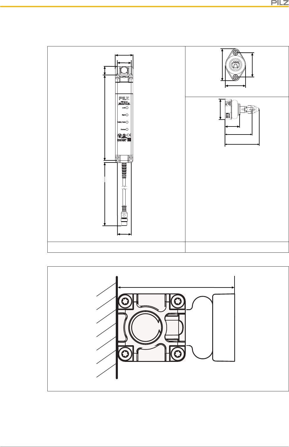
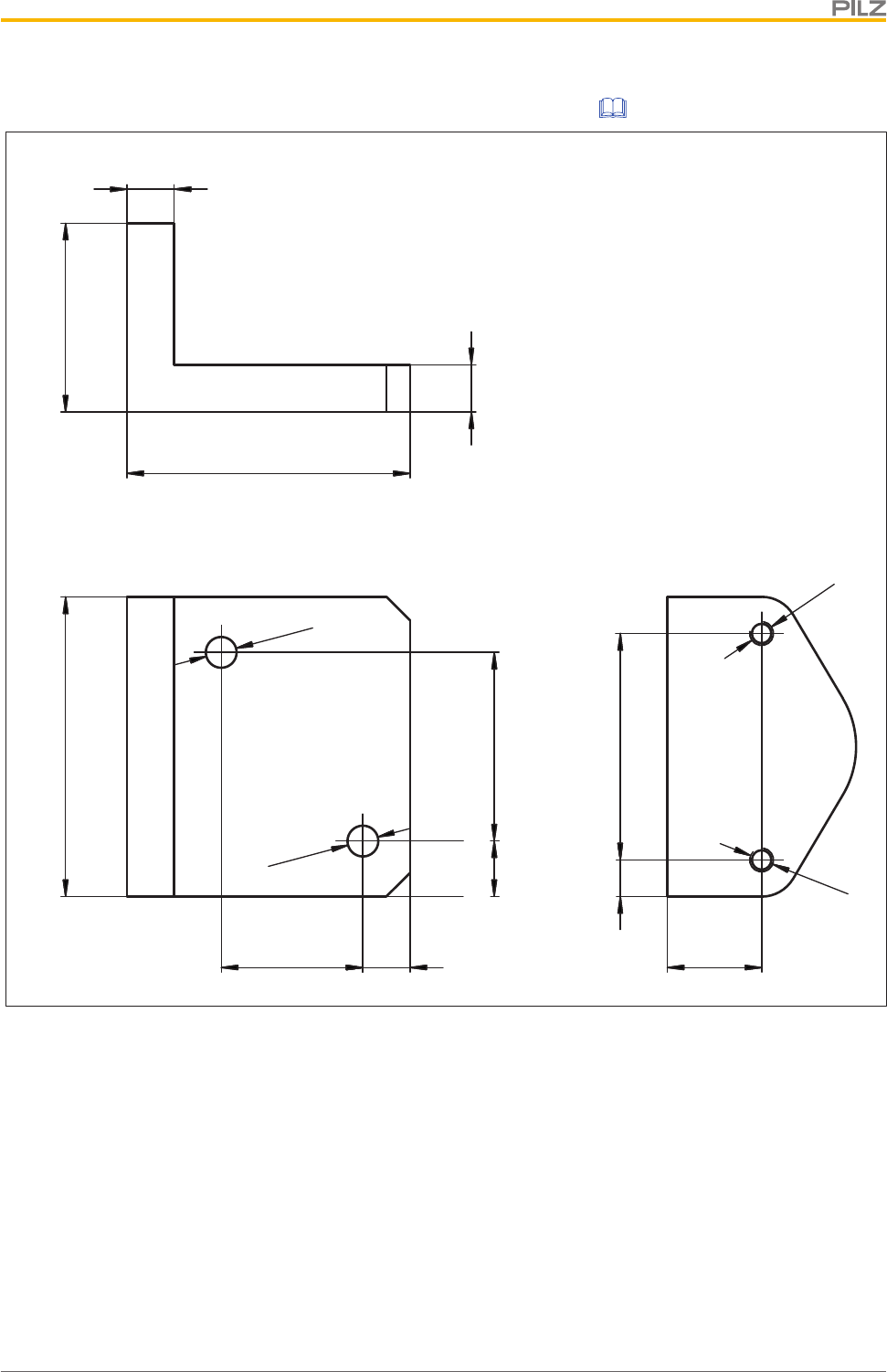
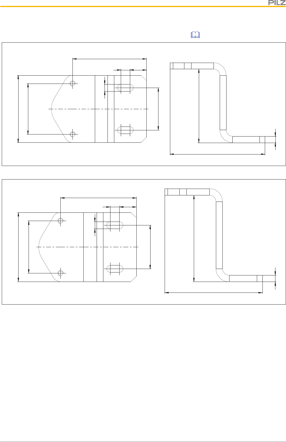
Dimensions
Operating Manual PSEN ml s 1.1
1004670-EN-01 58
12 Dimensions
31
19,2193,54,5
40
31
230
48
40
63,5
29
53
67
40
Safety switch Actuator
Distance between safety switch mounting surface and actuator mounting surface
69,5
Dimensions
Operating Manual PSEN ml s 1.1
1004670-EN-01 64
197
79,5
6
54
150
63,5
25
177
123
6,5
8,5
20
M5
Fig.: Order no.: 570497

Technical details
Operating Manual PSEN ml s 1.1
1004670-EN-01 65
13 Technical details
General
Approvals CE, FCC, IC, TÜV, cULus Listed
Sensor's mode of operation Transponder
Coding level in accordance with EN ISO 14119 Low
Design in accordance with EN ISO 14119 4
Classification in accordance with EN 60947-5-3 PDDB
Pilz coding type Coded
Transponder
Frequency band 122 kHz - 128 kHz
Max. transmitter output 15 mW
Electrical data
Supply voltage
Voltage 24 V
Kind DC
Voltage tolerance -20 %/+20 %
Output of external power supply (DC) 1 W
Max. switching frequency 1 Hz
Magnet. supply voltage 24 V
Max. solenoid current t <150 ms 1 A
Max. cable capacitance at the safety outputs
No-load, PNOZ with relay contacts 40 nF
PNOZmulti, PNOZelog, PSS 70 nF
Max. inrush current impulse
Current pulse, A1 5 A
Pulse duration, A1 0,0002 ms
Max. unit fuse protection in accordance with UL 3 A
No-load current 40 mA
Inputs
Number 4
Voltage at inputs 24 V DC
Current at solenoid input 500 mA
Input current range 1,6 - 3 mA
Semiconductor outputs
OSSD safety outputs 2
Signal outputs 1
Switching current per output 100 mA
Breaking capacity per output 2,4 W
Potential isolation from system voltage No
Short circuit-proof yes
Residual current at outputs 100 µA
Voltage drop at OSSDs 1 V
Conditional rated short circuit current 100 A
Technical details
Operating Manual PSEN ml s 1.1
1004670-EN-01 66
Semiconductor outputs
Lowest operating current 1 mA
Utilisation category in accordance with EN 60947-1 DC-13
Times
Test pulse duration, safety outputs 450 µs
Switch-on delay
after UB is applied 1,1 s
Inputs typ. 1 ms
Inputs max. 3 ms
Actuator typ. 30 ms
Actuator max. 50 ms
Delay-on de-energisation
Inputs typ. 3 ms
Inputs max. 5 ms
Actuator typ. 30 ms
Actuator max. 40 ms
Risk time in accordance with EN 60947-5-3 260 ms
Supply interruption before de-energisation 20 ms
Simultaneity, channel 1 and 2 max. 20 ms
Pulse duration Lock/Unlock Request 350 - 400 ms
Processing time activate/deactivate guard locking 100 ms
Environmental data
Temperature of metal surface at ambient temperat-
ure: 25 °C 40 °C
Ambient temperature
In accordance with the standard EN 60068-2-14
Temperature range 0 - 60 °C
Storage temperature
In accordance with the standard EN 60068-2-1/-2
Temperature range -25 - 70 °C
Climatic suitability
In accordance with the standard EN 60068-2-78
Humidity 93 % r. h. at 40 °C
EMC EN 55011: class A, EN 60947-5-3, EN 61326-3-1
Vibration
In accordance with the standard EN 60068-2-6
Frequency 10 - 55 Hz
Amplitude 1 mm
Shock stress
In accordance with the standard EN 60068-2-27
Number of shocks 3
Acceleration 30g
Duration 11 ms
Airgap creepage
Overvoltage category III
Pollution degree 3

Technical details
Operating Manual PSEN ml s 1.1
1004670-EN-01 67
Environmental data
Rated insulation voltage 75 V
Rated impulse withstand voltage 0,8 kV
Protection type
Housing IP67
In accordance with UL type 1
Mechanical data
Length of cable with connector 230 mm
Min. bending radius (fixed permanently) K1 5 x Ø
Min. bending radius (moving) K1 10 x Ø
Cable diameter K1 6,5 mm
Escape release available No
Mechanical life 1,000,000 cycles
Holding force FZh
Fixing screws in parallel to actuator 7.500 N
Fixing screws side-on to actuator 5.000 N
Holding force F1Max in accordance with ISO 14119
Fixing screws in parallel to actuator 15.000 N
Fixing screws side-on to actuator 10.000 N
Latching force 30 N
Max. vertical offset +/-3,0 mm
Max. lateral offset +/-3,0 mm
Max. angular offset around the X axis +/-2,0 deg
Max. angular offset around the Y axis +/-2,5 deg
Max. angular offset around the Z axis +/-7,5 deg
Max. offset in closing direction +/-2 mm
Max. retract speed of actuator 0,3 m/s
Actuator 1 PSEN ml 1.1
Min. distance between safety switches 0 mm
Connection type M12, 12-pin male connector
Cable LiYY 12 x 0.25 mm2
Material Aluminium, stainless steel, plastic, galvanised
steel, Zn
Max. torque setting for fixing screws 6 - 6,5 Nm
Max. torque setting escape release 1,2 - 1,5 Nm
Max. torque setting for mounting plate 22 - 24 Nm
Max. torque setting for mounting bracket 14 - 16 Nm
Min. gate radius 300 mm
Dimensions
Height 217,2 mm
Width 40 mm
Depth 40 mm
Actuator dimensions
Height 63,5 mm
Width 40 mm
Depth 67,2 mm
Technical details
Operating Manual PSEN ml s 1.1
1004670-EN-01 68
Mechanical data
Weight of safety switch 950 g
Weight of actuator 145 g
Weight 1.100 g
Where standards are undated, the 2015-11 latest editions shall apply.
13.1 Classification according to ZVEI, CB24I
The following tables describe the classes and specific values of the product interface and
the classes of interfaces compatible with it. The classification is described in the ZVEI posi-
tion paper "Classification of Binary 24 V Interfaces - Functional Safety aspects covered by
dynamic testing".
Inputs
Drain Source
Safety switch C2 Safety control system C2, C3
Drain parameters Min. Typ. Max.
Test impulse duration - - 500 µs
Input resistance 9 kOhm - -
Capacitive load - - 1 nF
Test impulse interval 1 ms - -
Solenoid inputs
Drain Source
Safety switch C2 Safety control system C2, C3
Drain parameters Min. Typ. Max.
Test impulse duration - - 500 µs
Input resistance 16 Ohm -
Capacitive load - - 1,5 nF
Safe 1-pole HL outputs
Source Drain
Safety switch C2 Evaluation device C1, C2
Technical details
Operating Manual PSEN ml s 1.1
1004670-EN-01 69
Source parameters Min. Typ. Max.
Test impulse duration - - 450 µs
Rated current - - 0,1 A
Capacitive load - - 70 nF
13.2 Safety characteristic data
NOTICE
You must comply with the safety characteristic data in order to achieve the
required safety level for your plant/machine.
Operating
mode
EN ISO
13849-1:
2015
PL
EN ISO
13849-1:
2015
Category
EN IEC
62061
SIL CL
EN IEC
62061
PFHD [1/h]
Lambda d/
Lambda
EN ISO
13849-1
2015, EN
IEC
B10D
EN ISO
13849-1:
2015
TM [year]
1-ch. guard
locking PL d Cat. 2 SIL CL 2 2,54E-08 ––20
2-ch. guard
locking PL e Cat. 4 SIL CL 3 2,54E-08 ––20
2-ch. OSSD PL e Cat. 4 SIL CL 3 1,90E-08 ––20
All the units used within a safety function must be considered when calculating the safety
characteristic data.
INFORMATION
A safety function's SIL/PL values are not identical to the SIL/PL values of
the units that are used and may be different. We recommend that you use
the PAScal software tool to calculate the safety function's SIL/PL values.
NOTICE
Be sure that you observe the mechanical life. The safety characteristic data
are only valid as long as the values of mechanical life are met.
Supplementary data
Operating Manual PSEN ml s 1.1
1004670-EN-01 70
14 Supplementary data
14.1 Radio approval
USA/Canada
FCC ID:
IC:
FCC/IC-Requirements:
This product complies with Part 15 of the FCC Rules and with Industry Canada licence-exempt RSS standards.
Operation is subject to the following two conditions:
1) this product may not cause harmful interference, and
2) this product must accept any interference received, including interference that may cause undesired operation.
Changes or modifications made to this product not expressly approved by Pilz may void the FCC authorization to operate this equipment.
NOTE: This equipment has been tested and found to comply with the limits for a Class A digital device, pursuant to Part 15 of the FCC Rules.
These limits are designed to provide reasonable protection against harmful interference when the equipment is operated in a commercial
environment. This equipment generates, uses, and can radiate radio frequency energy and, if not installed and used in accordance with the
instruction manual, may cause harmful interference to radio communications. Operation of this equipment in a residential area is likely to cause
harmful interference in which case the user will be required to correct the interference at his own expense.
Le présent produit est conforme aux CNR d'Industrie Canada applicables aux appareils radio
exempts de licence. L'exploitation est autorisée aux deux conditions suivantes:
(1) le produit ne doit pas produire de brouillage, et
(2) l'utilisateur de le produit doit accepter tout brouillage radioélectrique subi, même si le brouillage est susceptible d'en compromettre le
fonctionnement.
VT8-PSENML
7482A-PSENML
14.2 Technical details for mounting bracket without handle unit
General 570492 570493 570494
Approvals CE CE CE
Mechanical data 570492 570493 570494
Holding force FZh in ac-
cordance with ISO 14119 – 3000 N 3000 N
Holding force F1max in
accordance with ISO
14119 – 6000 N 6000 N
Weight 420 g 420 g 445 g
14.3 Technical details for mounting bracket with handle unit
General 570495 570496 570497
Approvals CE CE CE
Mechanical data 570495 570496 570497
Holding force FZh in ac-
cordance with ISO 14119 3000 N 3000 N 3000 N
Holding force F1max in
accordance with ISO
14119 6000 N 6000 N 6000 N
Weight 260 g 600 g 630 g

Order reference
Operating Manual PSEN ml s 1.1
1004670-EN-01 71
15 Order reference
15.1 System
Product type Features Order no.
PSEN ml s 1.1 unit Mechanical safety gate system with
guard locking, coded, for series con-
nection
12-pin M12 connector 570 406
PSEN ml s 1.1
switch
Mechanical safety gate switch with
guard locking, coded, for series con-
nection
12-pin M12 connector 570 407
PSEN ml 1.1 actu-
ator
Actuator, coded 570 480
15.2 Accessories
Installation accessories
Product type Features Order no.
PSEN ml escape re-
lease
Escape release stationary 570 460
PSEN ml escape re-
lease extension
Extension escape release stationary 25 mm 570 462
PSEN ml escape re-
lease cordset 1.5m
Escape release with push/pull cable 1.5 m 570 470
PSEN ml escape re-
lease cordset 2.0m
Escape release with push/pull cable 2 m 570 471
PSEN ml escape re-
lease cordset 2.5m
Escape release external with push/pull cable 2.5 m 570 472
PSEN ml escape re-
lease cordset 3.0m
Escape release with push/pull cable 3.0 m 570 473
PSEN ml escape re-
lease cordset 3.5m
Escape release with push/pull cable 3.5 m 570 474
PSEN ml escape re-
lease cordset 4.0m
Escape release with push/pull cable 4 m 570 475
PSEN ml mounting
plate
Mounting plate for installing the safety switch, with 4 hexagonal
socket head screws and 1 tamper-proof pan head locking screw,
M5x40
570490
PSEN ml bracket
sliding door
Mounting bracket for installing the actuator on a sliding gate, with 2
hexagonal socket head screws and 1 tamper-proof pan head lock-
ing screw, M5x16
570 492
PSEN ml bracket
swinging door 70
Mounting bracket for installing the actuator on a swing gate, with 2
hexagonal socket head screws and 1 tamper-proof pan head lock-
ing screw, M5x12. Height: 70 mm.
570 493

Order reference
Operating Manual PSEN ml s 1.1
1004670-EN-01 72
Product type Features Order no.
PSEN ml bracket
swinging door 80
Mounting bracket for installing the actuator on a swing gate, with 2
hexagonal socket head screws and 1 tamper-proof pan head lock-
ing screw, M5x12. Height: 80 mm.
570 494
PSEN ml door
handle sliding door
Mounting bracket with handle unit for installing the actuator on a
sliding gate, with 2 hexagonal socket head screws and 1 tamper-
proof pan head locking screw, M5x16.
570 495
PSEN ml door
handle swinging
door 70
Mounting bracket with handle unit for installing the actuator on a
swing gate, with 2 hexagonal socket head screws and 1 tamper-
proof pan head locking screw, M5x12. Height: 70 mm.
570 496
PSEN ml door
handle swinging
door 80
Mounting bracket with handle unit for installing the actuator on a
swing gate, with 2 hexagonal socket head screws and 1 tamper-
proof pan head locking screw, M5x12. Height: 80 mm.
570 497
PSEN screw set
bracket swinging
door
Screw sets for attaching the mounting bracket to a swing gate 570498
PSEN screw set
bracket sliding door
Screw sets for attaching the mounting bracket to a sliding gate 570499
Cable
Product type Features Connector X1 Connector X2 Connector X3 Order no.
PSEN cable axial
M12 8-pole 3m
3 m M12, 8-pin fe-
male con-
nector, straight
540 319
PSEN cable axial
M12 8-pole 5m
5 m M12, 8-pin fe-
male con-
nector, straight
540 320
PSEN cable axial
M12 8-pole 10m
10 m M12, 8-pin fe-
male con-
nector, straight
540 321
PSEN cable
M12-8sf, 20m
20 m M12, 8-pin fe-
male con-
nector, straight
540 333
PSEN cable axial
M12 8-pole 30m
30 m M12, 8-pin fe-
male con-
nector, straight
540 326
PSEN cable
M12-8sf M12-8sm,
0.5m
0.5 m M12, 8-pin fe-
male con-
nector, straight
M12, 8-pin
male con-
nector, straight
540 345
PSEN cable
M12-8sf M12-8sm,
1m
1 m M12, 8-pin fe-
male con-
nector, straight
M12, 8-pin
male con-
nector, straight
540 346
PSEN cable
M12-8sf M12-8sm,
1.5m
1.5 m M12, 8-pin fe-
male con-
nector, straight
M12, 8-pin
male con-
nector, straight
540 347
PSEN cable
M12-8sf M12-8sm,
2m
2 m M12, 8-pin fe-
male con-
nector, straight
M12, 8-pin
male con-
nector, straight
540 340

Order reference
Operating Manual PSEN ml s 1.1
1004670-EN-01 73
Product type Features Connector X1 Connector X2 Connector X3 Order no.
PSEN cable
M12-8sf M12-8sm,
5m
5 m M12, 8-pin fe-
male con-
nector, straight
M12, 8-pin
male con-
nector, straight
540 341
PSEN cable
M12-8sf M12-8sm,
10m
10 m M12, 8-pin fe-
male con-
nector, straight
M12, 8-pin
male con-
nector, straight
540 342
PSEN cable
M12-8sf M12-8sm,
20m
20 m M12, 8-pin fe-
male con-
nector, straight
M12, 8-pin
male con-
nector, straight
540 343
PSEN cable
M12-8sf M12-8sm,
30m
30 m M12, 8-pin fe-
male con-
nector, straight
M12, 8-pin
male con-
nector, straight
540 344
PSEN cable
M12-12sf 2m
2 m M12, 12-pin fe-
male con-
nector, straight
570 350
PSEN cable
M12-12sf 3m
3 m M12, 12-pin fe-
male con-
nector, straight
570 351
PSEN cable
M12-12sf 5m
5 m M12, 12-pin fe-
male con-
nector, straight
570 352
PSEN cable
M12-12sf 10m
10 m M12, 12-pin fe-
male con-
nector, straight
570 353
PSEN cable
M12-12sf 20m
20 m M12, 12-pin fe-
male con-
nector, straight
570 354
PSEN cable
M12-12sf 30m
30 m M12, 12-pin fe-
male con-
nector, straight
570 355
PSEN cable
M12-12sf 50m
50 m M12, 12-pin fe-
male con-
nector, straight
570 356
PSEN cable
M12-12sf/
M12-12sm 1m
1 m M12, 12-pin fe-
male con-
nector, straight
M12, 12-pin
male con-
nector, straight
570 357
PSEN cable
M12-12sf/
M12-12sm 2m
2 m M12, 12-pin fe-
male con-
nector, straight
M12, 12-pin
male con-
nector, straight
570 358
PSEN cable
M12-12sf/
M12-12sm 3m
3 m M12, 12-pin fe-
male con-
nector, straight
M12, 12-pin
male con-
nector, straight
570 359
PSEN cable
M12-12sf/
M12-12sm 5m
5 m M12, 12-pin fe-
male con-
nector, straight
M12, 12-pin
male con-
nector, straight
570 360
PSEN cable
M12-12sf/
M12-12sm 10m
10 m M12, 12-pin fe-
male con-
nector, straight
M12, 12-pin
male con-
nector, straight
570 361

Order reference
Operating Manual PSEN ml s 1.1
1004670-EN-01 74
Product type Features Connector X1 Connector X2 Connector X3 Order no.
PSEN cable
M12-12sf/
M12-12sm 20m
20 m M12, 12-pin fe-
male con-
nector, straight
M12, 12-pin
male con-
nector, straight
570 362
Series connection
Product type Features Connector X1 Connector X2 Connector X3 Order no.
PSEN ml Y junction
M12
M12, 8-pin
male connector
M12, 8-pin fe-
male connector
M12, 12-pin fe-
male connector
570 486
PSEN ml end ad-
apter
M12, 12-pin fe-
male connector
M12, 8-pin
male connector
570 487
PSEN ml / PSENcs
Y junction M12
M12, 8-pin fe-
male connector
M12, 8-pin
male connector
M12, 8-pin fe-
male connector
570 489
Appendix
Operating Manual PSEN ml s 1.1
1004670-EN-01 75
16 Appendix
The following check list is intended as a guide to provide support during commissioning, re-
commissioning and the prescribed regular testing of the PSEN ml s 1.1.
Note that the check list is not intended to replace the plant-specific safety analysis required
for commissioning/recommissioning, nor the resulting inspections and actions.
INFORMATION
Commissioning, recommissioning and regular inspection may only be car-
ried out by qualified personnel.
We recommend that you keep the completed check list and store it with the machine docu-
mentation for reference.
Date Action
Safety
switch
Number
Actuator
Number OK Not OK Notes Signature

EC declaration of conformity
Operating Manual PSEN ml s 1.1
1004670-EN-01 76
17 EC declaration of conformity
This product/these products meet the requirements of the directive 2006/42/EC for ma-
chinery of the European Parliament and of the Council. The complete EC Declaration of
Conformity is available on the Internet at www.pilz.com/downloads.
Authorised representative: Norbert Fröhlich, Pilz GmbH & Co. KG, Felix-Wankel-Str. 2,
73760 Ostfildern, Germany
The Best of
German
Engineering
Partner of:
Support
Technical support is available from Pilz round the clock.
Americas
Brazil
+55 11 97569-2804
Canada
+1 888-315-PILZ (315-7459)
Mexico
+52 55 5572 1300
USA (toll-free)
+1 877-PILZUSA (745-9872)
Asia
China
+86 21 60880878-216
Japan
+81 45 471-2281
South Korea
+82 31 450 0680
Australia
+61 3 95600621
Europe
Austria
+43 1 7986263-0
Belgium, Luxembourg
+32 9 3217575
France
+33 3 88104000
Germany
+49 711 3409-444
Ireland
+353 21 4804983
Italy, Malta
+39 0362 1826711
Scandinavia
+45 74436332
Spain
+34 938497433
Switzerland
+41 62 88979-30
The Netherlands
+31 347 320477
Turkey
+90 216 5775552
United Kingdom
+44 1536 462203
You can reach our
international hotline on:
+49 711 3409-444
support@pilz.com
CMSE®, InduraNET p®, PAS4000®, PAScal®, PASconfig®, Pilz®, PIT®, PLID®, PMCprimo®, PMCprotego®, PMCtendo®, PMD®, PMI®, PNOZ®, Primo®, PSEN®, PSS®, PVIS®, SafetyBUS p®,
SafetyEYE®, SafetyNET p®, THE SPIRIT OF SAFETY® are registered and protected trademarks of Pilz GmbH & Co. KG in some countries. We would point out that product features may vary
from the details stated in this document, depending on the status at the time of publication and the scope of the equipment. We accept no responsibility for the validity, accuracy
and entirety of the text and graphics presented in this information. Please contact our Technical Support if you have any questions.
Pilz develops environmentally-friendly products using
ecological materials and energy-saving technologies.
Oces and production facilities are ecologically designed,
environmentally-aware and energy-saving. So Pilz oers
sustainability, plus the security of using energy-ecient
products and environmentally-friendly solutions.
Pilz GmbH & Co. KG
Felix-Wankel-Straße 2
73760 Ostfildern, Germany
Tel.: +49 711 3409-0
Fax: +49 711 3409-133
info@pilz.com
www.pilz.com
200XXXX-EN-0X
0-0-2-3-000, 2017-00 Printed in Germany
© Pilz GmbH & Co. KG, 2017
Front cover
1004670-EN-01, 2018-04 Printed in Germany
© Pilz GmbH & Co. KG, 2015