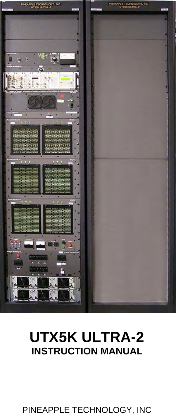
Pineapple Technology UTX5KULTRA-2 5 kW Analog Broadcast TV Transmitter User Manual

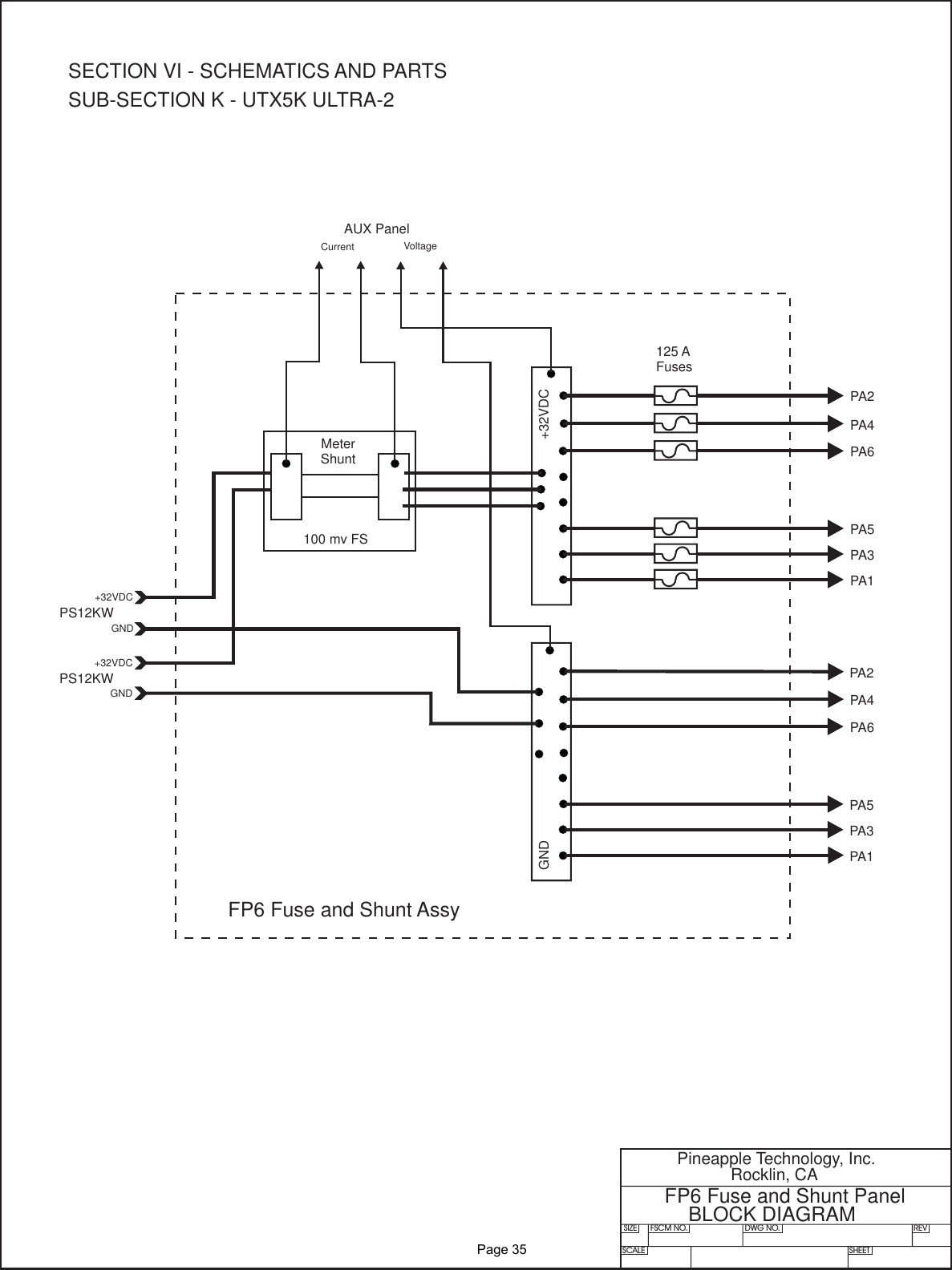
Pineapple Technology, Inc. 5 kW Analog Broadcast TV Transmitter

User Manual

UTX5K ULTRA-2INSTRUCTION MANUALPINEAPPLE TECHNOLOGY, INC
PINEAPPLE TECHNOLOGY, INC.  UTX5K ULTRA-2  Operating and Service Manual TABLE OF CONTENTSSection l --- SAFETY NOTICES    …………………………………………………………………………2** READ THIS SECTION BEFORE INSTALLATON **Secton ll --- TRANSMITTER SPECIFICATIONS   …………………...…………………………………3Section lll --- TRANSMITTER INSTALLATION   ………………………………………………………5Section lV --- TRANSMITTER TURN-ON   ………………………………………………………………7Section V --- THEORY OF OPERATION  A. Introduction   ………………………………………………………………………………8B. ACDIS4 AC Main Distribution   ………………………………………………………… 8C. PS12KW Power Supply   …………………………………………………………………8D. PAS6 and ADP500 Performance Monitor   ……………………………………………9E. RC8 Remote Monitor and Control W/ABS   ……………………………………………10F. MA2000 Modulator  ……………………………………………………………………… 10G. UDR100AC Driver   ………………………………………………………………………11H. S6 6-Way Splitter   …………………………………………………………………………11I.  MFA2PA Dual Power Amplifier   …………………………………………………………11J. UC6KWN 6-Way Combiner   …………………………………………………………… 12K. BPU10K Bandpass Filter   ……………………………………………………………… 12L. DC7KW Directional Coupler………………………………………………………………12M. AUX Monitor Panel   ………………………………………………………………………12N. FP6 Fuse and Distribution Panel   ………………………………………………………12SECTION Vl --- SCHEMATIC AND PARTS LISTSA. UTX5K ULTRA   ………………………………………………………….......................13B. ACDIS4 AC Main Distribution   ………………………………………………………… 15C. UDR100AC Driver   ………………………………………………………………………17D. MFA2PA Dual Power Amplifier   …………………………………………………………191. 1A0035 Status Board   …………………………………………………………212. PA1K 1KW Power Module   ……………………………………………………23a. U500LDA 500 W Amplifier   …………………………………………23b. U250LD 250 W Amplifier   …………………………………………23c. 1A0025 Power Distribution Monitor   ………………………………23d. 1A0018 Gain and Phase Matching Network   ……………………23E. S6 6-Way Splitter   …………………………………………………………………………25F. UC6KWN 6-Way Combiner………………………………………………………………27G. DC7KW Directional Coupler………………………………………………………………28H. BPU10KW Bandpass Filter   …………………………………………………………… 29I.  PAS6 and ADP500 Performance Monitor   …………………………………………… 30J. AUX Monitor Panel   ………………………………………………………………………32K. FP6 Fuse and Shunt Panel   …………………………………………………………… 34SECTION Vll --- RECOMMENDED ROUTINE MAINTENANCE   ……………………………………36SECTION Vlll --- ADJUSTMENTS AND TUNING   …………………………………………………… 38SECTION lX --- PROBLEM SOLVING / TROUBLESHOOTING   ……………………………………40SECTION X --- WARRANTY   …………………………………………………………………………… 43SECTION Xl --- EXTENDED WARRANTY …………………………………………………………..
Section ISafetyNotices
PINEAPPLE TECHNOLOGY, INC.  UTX5K ULTRA - 2  Operating and Service Manual l --- SAFETY NOTICESl ---SAFETY NOTICES** READ THIS SECTION BEFORE INSTALLATION **SEVERE ELECTRICAL SHOCK OR BURNS MAY OCCUR      IF THIS EQUIPMENT IS USED IMPROPERLY.NEVER WORK ON THIS EQUIPMENT ALONE. ALWAYS HAVE ANOTHER PERSON PRESENTWHILE WORKING ON ELECTRICAL CIRCUITS OR MOVING EQUIPMENT. COMMUNICATIONS                  TO EMERGENCY SERVICES SHOULD BE AVAILABLE AT ALL TIMES.   BEFORE CONNECTING THIS EQUIPMENT TO ANY AC ELECTRICAL SOURCE READ THE  SECTION ON INSTALLATION. ALL ELECTRICAL WIRING FOR THIS EQUIPMENT MUST BE    PERFORMED BY QUALIFIED ELECTRICIANS. ALL WIRING MUST BE COMPLIANT WITH                                                 LOCAL ELECTRICAL CODES.POWER AMPLIFIERS AND SUPPLIES ARE HEAVY. TO INSTALL THIS EQUIPMENT IN RACKS                         USE TWO (2) PERSONS TO AVOID POSSIBLE INJURIES.NEVER OPEN THE CABINET ENCLOSURE OR UNPLUG CABLES OR WIRES WHILE THIS                                             EQUIPMENT IS OPERATING.       ALL SERVICE WORK MUST BE PERFORMED BY QUALIFIED TECHNICIANS ONLY.   IF ONE IS NOT AVAILABLE LOCALLY, CONTACT PINEAPPLE TECHNOLOGY, INC. FOR                                                  A LIST IN YOUR AREA.              Page 2
Section IITransmitterSpecifications
THESE SPECIFICATIONS ARE SUBJECT TO CHANGE WITHOUT NOTICE.          PINEAPPLE TECHNOLOGY, INC.                UTX5K ULTRA - 2 Operating and Service Manual                II – TRANSMITTER SPECIFICATIONS    II – UTX5K ULTRA - 2 SPECIFICATIONS  OPERATING  Power Output …………………………  5KW Peak Sync                                          500 Watts Aural  RF Output Impedance…………………  50 ohms  Frequency Range……………………… 470 – 806 MHz  Frequency Stability……………………  1 PPM or better  Harmonic and Spurious………………... -60 db or better ref to P-sync  Power Consumption……………………22 KW maximum  AC Line Voltage………………………  208 – 230 VAC 3-Phase (Standard)                                                                  222 – 240 VAC Single Phase (Optional)   VIDEO PERFORMANCE  Visual Frequency Response…………… +/- 1 db across the TV channel -1.25 MHz to 4.75 Mhz                                                                   relative to visual carrier.  Differential Gain…………………………… .< 7%  Differential Phase…………………………... < 10 degrees  ICPM………………………………………..< 5 degrees  Low Frequency Linearity………………….. < 15%  Group Delay……………………………….. Meets FCC Part 73 Rule  Video Input Impedance……………………. 75 ohms  Video Input Level………………………….. 1 volt p-p  Variation of Output Power…………………. < 5%  Regulation of Output Power……………….. < 5% typical  Video Signal to Noise Ratio……………….. < 45 db un-weighted                    Page 3
THESE SPECIFICATIONS ARE SUBJECT TO CHANGE WITHOUT NOTICE.          PINEAPPLE TECHNOLOGY, INC.                UTX5K ULTRA - 2 Operating and Service Manual                II – TRANSMITTER SPECIFICATIONS    AUDIO PERFORMANCE   Audio Response…………….…………. Meets FCC Pre-emphasis curve  Distortion…………………………………….< 1% THD  FM Noise…………………………............... < 50 db or better  AM Noise……………………………………< 40 db or better  AM Synchronous Noise……………………. < 40 db typical   GENERAL   Operating Temperature…………………….. -10 to +35 Degrees Celsius Ambient      +14 to +95 Degrees Fahrenheit Ambient  Altitude…………………………………….. 5,000 ft without additional cooling  Cooling Requirement………………………. Unobstructed air flow to internal cooling system should      be 2500 CFM minimum  RF Output Connectors………………………1 5/8” EIA Flange  Weight………………………………………1400 lbs  Dimensions Overall…………………………84” x 44” x 42”  (H x W x D), 2 rack system                                                                                          Page 4
Section IIITransmitterInstallation
PINEAPPLE TECHNOLOGY, INC.  UTX5K ULTRA - 2  Operating and Service Manual lll -- TRANSMITTER INSTALLATIONlll -- TRANSMITTER INSTALLATION Page 1 of 2To ensure long and reliable trouble-free service from the UTX5K ULTRA-2 transmitter the following stepsfor installation are recommended:1. MECHANICAL INSTALLATION: The UTX5K ULTRA-2 was designed to be installed in a buildingprotected from the weather. The building should have a hard-surface floor such as concrete with a moisture barrier. This barrier could be pressure-treated wood sub flooring which could be anchoredto the concrete and to the transmitter to make the installation earthquake resistant.Allow a minimum of three feet around the transmitter cabinet for service access. The top of thetransmitter should be clear for three feet above to allow the air to exhaust from the transmitter.Air flow thru the transmitter is approximately 2,000 CFM. Provisions for air inlet and exhaust fromthe room must allow air flow with minimal obstruction. In the event that the room temperatureexceeds 35º Celsius (95º F), cooling air must be provided so that the room temperature will notexceed 35 degrees Celsius under worse case conditions.Notice: This equipment is HEAVYand must be handled by professional movers with properequipment. Any damage caused by the installers is not covered under warranty. Check to ensurethat installing crews have proper insurance coverage.2. GROUNDING: Transmitter grounding is VERY IMPORTANT and must be done correctly forsafety and operational reasons. A typical installation may be done as follows:Use a heavy gauge wire such as #2 AWG stranded copper or solid copper buss one (1) inch wideby 1/8 inch thick for connections. The bonding between the transmitter and the ground rods mustbe good quality and protected from corrosion. The ground wires should run over the floor and beconnected to the ground rods located outside the building. The wire should not go thru the concretefloor but over and around it.3. AC WIRING: Wiring to the house electrical sub-panel will be routed to the AC terminal block mounted in the back of the rack.208 VAC 3 Phase StandardPower Connections  Connections to the AC Main should be made as follows:  --- RED, BLACK AND ORANGE are connected to the 208 VAC 3-PHASE.  --- WHITE WIRE is connected to the NEUTRAL.  ---GREEN WIRE is connected to the SAFETY GROUND.220 VAC Single Phase OptionalPower Connections  Connections to the AC Main should be made as follows:  --- RED and BLACK are connected to the 220 VAC.  --- WHITE WIRE is connected to NEUTRAL.  ---GREEN WIRE is connected to SAFETY GROUND.NOTICE: All wiring of this type must be done by a QUALIFIED ELECTRICIAN and mustconform to LOCAL and NATIONAL wiring CODES.Consult with your electrician to ensure that the proper breaker size is selected for the main circuit.              Page 5
PINEAPPLE TECHNOLOGY, INC.  UTX5K ULTRA -2  Operating and Service Manual lll -- TRANSMITTER INSTALLATIONlll -- TRANSMITTER INSTALLATION Page 2 of 24.ANTENNA CONNECTION: The transmitter is equipped with 1 5/8" EIA flange connectors located at the top of the rack. Conditions vary from site to site so some engineering may be  required to ensure that the antenna is receiving the correct amount of power to comply with FCC licenses and to ensure safety from lightning, etc.               Page 6
Section IVTransmitterTurn-On
PINEAPPLE TECHNOLOGY, INC.  UTX5K ULTRA-2  Operating and Service Manual                  lV -- TRANSMITTER TURN-ON PROCEDURElV --- TRANSMITTER TURN-ON PROCEDUREBefore applying AC Power to the transmitter for initial turn-on and check out, the installation should be approved by a qualified broadcast engineer. The turn-on procedure that follows is recommended by Pineapple Technology, Inc. engineering staff:1. Check transmitter load or antenna for proper installation and connection to the transmitter.2. Open the transmitter and inspect all cables and wires for loose connections or broken wires in the rack assembly.3. Check for damage to the equipment mounted in the racks.4. Check all AC breakers and on/off switched to ensure that they are all in the OFF position.5. Turn-on the Main AC breaker(s) located in the house service sub-panel.6. Turn-on the Main AC breaker (CB-1) on the  ACDIS5 Power Distribution panel. Each panel should display a light   indicating power is on. 7. Turn-on CB13 on the ACDIS5 panel. The AUX Panel should now have the green AC ON lamp lighted. This supplies power to the AC duplex outlets on the AUX panel.8. Turn-on CB12 on each ACDIS5 panel. This supplies 110 VAC power to the transmitter9. Turn-on the AC Power switch located on the front panel of the ADP500. The indicating lights should be on and ready for operation.10. Turn-on the AUX breaker CB-2 located on the ACDIS5 Power Distribution panel. The PA Fans and the rack exhaust   Fan should come on.11. Turn-on the power supply breakers, CB-3 thru CB-8, located on the ACDIS5 Power panel. Check the PS12KW Power  Supply to see if the green lights are on indicating normal operation. (Note: There are six green lights is the PS12KW) 12. Using the ADP500 and PAS6 panel, check the idling currents on each PA to ensure that the currents are in the   correct range. Typical range is 0.5 to 2.5 Amps. See ADP500 Operating Section for details. Turn the rotary switch to  the P FWRD position.  NOTICE:  The Modulator has been set at the factory so that the output power indication on the ADP500 will show 100% or 2 KW p-sync power level. It is important to read the instruction manual supplied with the modulator to locate key  adjustment devices on the front panel. The output level adjustment will be necessary for the next step in the turn-on procedure.13. Turn-on the power switch located on the UDR100AC front panel.14. Apply a video signal (1 volt P-P) to the video input terminal.15. Verify the display rocker switch on the MA2000 Modulator is in the VIDEO or down position and three (3) green bars appear on the display bar graph.16. Slowly increase the output level adjustment while watching the RF Output level on the APD500 meter until it reads to 50%.17. Using the ADP500 reflected power indication, check the LOAD reflected power. This should be less than 5% reflected.18. Return to the PA current readings on the ADP500 to verify that all the currents are approximately the same.19. With successful performance to Step 17, the transmitter output power can be increased using the output level adjustment on the modulator to achieve 100%. The aural power can be added at this time not exceeding 10% of output p-sync power as indicated on the ADP500.              Page 7
Section VTheoryofOperation
PINEAPPLE TECHNOLOGY, INC.  UTX5K ULTRA-2  Operating and Service Manual                   V -- THEORY OF OPERATIONV --- THEORY OF OPERATION  (Page 1 of 5)A. INTRODUCTIONThe UTX5K ULTRA-2 transmitter was designed to meet or exceed all FCC applicable specifications forTV broadcast equipment. Special attention was given to the selection of sub-assemblies and componentsto achieve maximum reliability and minimum down time. The construction of the UTX5K ULTRA-2 isBASIC and MODULAR with most components field replaceable. Special emphasis was placed on"KEEPING IT SIMPLE" and returning to more traditional transmitter layouts and instrumentation.This transmitter was designed for Analog (NTSC) transmission with provisions and options available toconvert to Digital Service at a later date if necessary.Refer to the UTX5K ULTRA-2 block diagram for an overview of the transmitter architecture. This will givethe technician basic information needed to understand the operation of the transmitter and the function of each subassembly.SEE SECTION Vl.A  FOR PARTS LIST AND BLOCK DIAGRAM.B. ADCIS5 AC DISTRIBUTIONThe ACDIS5 is the primary AC power inlet for the transmitter. The UTX5K ULTRA-2 transmitter was designed for Standard 208 to 230 VAC 3-Phase using a FIVE (5) wire connection. The transmitter can be Optionally powered as 220 to 240 VAC Single Phase using a four (4) wire connection.Standard                Optional--- 3 wires for 208 - 240 VAC 3 Phase--- 2 wires for 220 -240 VAC Single Phase--- 1 wire for neutral connection --- 1 wire for neutral connection--- 1 wire for safety ground connection--- 1 wire for safety ground connectionCAUTION: Connection to the AC Primary source must be made using all five wires listed above. Followthe wiring instruction given in TRANSMITTER INSTALLATION Section lll.3. If not followed, severe damage tothe transmitter and, or, electrical shock could result.The ACDIS5 performs the following functions:1. Provides a primary AC power breaker point to shutdown the transmitter.2. Provides 208 VAC power to each of the 2.2KW DC power supplies with individual breaker points foradded safety.3. Provides 110 VAC circuits for Modulator,ADP500, ABS (as necessary) and AUX Power whereneeded.SEE SECTION Vl.B FOR SCHEMATIC AND PARTS LISTC. PS12KW POWER SUPPLYThe UTX5K ULTRA-2 transmitter is designed with over 12 KW of DC power. To achieve this level, the modulesmounted in the power supply in the transmitter rack consist of six (6) AC2008 power units with two (2)AC2009 main frame assemblies each of which are capable of managing three (3) 2 KW modules each.The power modules are "HOT PLUGGABLE" and can be removed or installed without turning off thetransmitter.Each power supply module has OVER VOLTAGE, OVER CURRENT AND OVER TEMPERATUREprotection as well as a fault signal in the event of a failure.REFER TO MANUFACTURER'S MANUAL FOR MODEL # TWRI6004 PROVIDED WITH THE UTX5K ULTRA-2.              Page 8
PINEAPPLE TECHNOLOGY, INC.  UTX5K ULTRA-2  Operating and Service Manual                   V -- THEORY OF OPERATION(CONTINUED)  Page 2 of 5D. ADP500 AND PAS6 PERFORMANCE MONITORThe ADP500 and PAS6 Performance Monitor provides the following functions:1. Monitors FORWARD AND REFLECTED POWER to the hybrid combiner and presents it as a percentageof power rating. The transmitter comes set to 100% P-Sync power based on the ratings of the transmitter.2. Provides a HIGH ANTENNA VSWR MONITOR in the event of an antenna or coax failure wherethe reflected power exceeds 25% the transmitter will shut down. The front panel LED will changefrom green to red in case of a fault.3. Provides current monitoring of all the pallets used in the six (6) PA1K power amplifier assemblies. The  current levels can be read directly from the multi-meter on the front panel. Individual pallets are selectable on the ADP500 and the PA assemblies are selected using the PAS6. In normal operation, a PA FAULT is indicated by going from green to red. RED indicates that the current level is below 500 ma and a transistor could have failed. To read the actual current, select the appropriate PA Bank using the PAS6. The ADP500 will now display status of each pallet in that PA. The multi-meter will read the actual current.4.A PA INHIBIT switch is provided for failure diagonostic purposes. When activated, this switch allowsthe technician to monitor the bias currents for each pallet. These readings were recorded at the factoryand are found on the Transmitter Test Report, DC Test Report Section. This is the best way to troubleshoot possible transistor problems. When in the PA INHIBIT mode, the  RF PWR OFF LED will change from green to red indicating that the "SHUTDOWN LINE" is at TTL 0 state and the output power has been reduced to near zero.5.An RF MONITOR port (BNC) is available to connect a spectrum analyzer for monitoring the output signal.6. METER SELECTION SWITCHESThe PAS6 is used to select the appropriate PA Module (PA1K) for performance display on the ADP500.PA designations are PA1 starting from the top row going left to right with PA6 located on the bottom (3rd)row down on the right side when viewed from the front of the transmitter rack.The rotary switch on the ADP500 is the detail selector for the multi-meter. The various positons aredefined as follows:PA1 thru PA5……………………………………Reads PA Pallet currents as selectedTypical reading in INHIBIT MODE 1.5 to 2.5 ATypical reading SMPTE BARS 5-7 A for PA1 thru PA4Typical reading SMPTE BARS 2-3 A for PA5PA6………………………………………………No ConnectionPS VOLTS………………………………………Reads DC voltage applied to PA stagesTypical reading would be +29 to 33 VDCP FWRD…………………………………………Reads PA output power in P-Sync percentage of ratingFull power reading would be 100%              Page 9
PINEAPPLE TECHNOLOGY, INC.  UTX5K ULTRA-2  Operating and Service Manual                   V -- THEORY OF OPERATION(CONTINUED)  Page 3 of 57. METER SELECTION SWITCHESP RFLD…………………………………………Reads PA output power being returned from the load anddisplayed as a percentage of forward power. Typicalreading would be < 5% indicated.P AURAL……………………………………… Reads the AURAL POWER component as a percentageof forward power. Typical reading would be 5%AUX 1 & AUX 2…………………………………Not used in this configuration.E. RC8 REMOTE MONITOR AND CONTROL WITH ABSThis equipment is OPTIONAL and can be used to satisfy FCC remote control requirements.The Remote Monitor is used to monitor the operational status of the transmitter and will allow theoperator to turn RF on or off and adjust power levels remotely. The following items are monitored or controlled:1. Transmitter on/off function2. Power output level monitor and adjust3.AC Line Voltage status - With ABS you can be notified if there is a power failure at the site.4. Various other custom options are available. Specify these at the time the transmitter is purchased and they will be included if possible.Remote monitoring requires a phone line connection. Information can be accessed via a PC Terminal.The Auxiliary power unit requires a battery connection. A common car battery (12 VDC) can be usedwith a charger as an ABS. This will run the Monitor and provide access to transmitter status for severalhours.A manual for this equipment is provided by the Manufacturer and is included in the UTX5K ULTRApackage shipped with the transmitter. The manual is only included if this option was purchased fordelivery with the transmitter.REFER TO INSTRUCTION MANUAL PROVIDED WITH THIS PACKAGE.F. MA2000 MODULATORThe heart of any TV Transmitter is the MODULATOR. This equipment receives the video and audiosignals was well as any control signals needed. The base band signals are converted to RF with anoutput on the desired operating channel.Detail operation of the Modulator with schematics and parts list are provided by the equipmentmanufacturer and included in the UTX5K ULTRA-2 package shipped with the transmitter.REFER TO INSTRUCTION MANUAL PROVIDED WITH THIS PACKAGE.              Page 10
PINEAPPLE TECHNOLOGY, INC.  UTX5K ULTRA-2  Operating and Service Manual                   V -- THEORY OF OPERATION(CONTINUED)  Page 4 of 5G. UDR100AC 100 WATT DRIVER AMPLIFIERThe RF output from the MA2000 Modulator is applied to the input of the UDR100AC driver amplifier. This amplifier increases the drive level to that required for each of the six (6) PA1K  power amplifiers to make rated power. The  UDR100AC is powered by 110 VAC.REFER TO SECTION Vl.C. FOR SCHEMATIC DIAGRAM AND PARTS LIST.H. S6 6-WAY SPLITTERThe S6 Splitter is an 6-Way  in-phase broadband splitter. This splitter provides an equal split of drive power to each of the six (6) PA1K power amplifiers in each transmitter rack.SEE SECTION Vl.G. FOR PARTS LISTI. MFA2PA POWER AMPLIFIER HOUSINGThe MFA2PA is the main RF Power Amplifier housing which accommodates two (2) PA1K Amplifiers.The housing includes the following:2 each 330 CFM cooling fans2 eachAir filter assemblies2 each  Front panel status PC boards1 each Main chassis2 each Mechanical slide assemblies1 eachAC Filtered inle for cooling fansSEE SECTION Vl.D FOR SCHEMATICS AND PARTS LIST I-1. PA1K POWER AMPLIFIERThe PA1K is the main RF Power Amplifier Assembly used in the UTX5K ULTRA.Each amplifier assembly is made up of one (1) U250LD power pallet and two (2) U500LDA powerpallets. These amplifiers are operated in Class A/AB or sometimes referred to as "HARD AB". This refers to the bias levels to achieve best linerarity.Each PA1K amplifier assembly includes the following:1 each U250LD power pallets2 each U500LDA power pallets1 each Phase and gain matching circuit1 each 2-Way in-phase splitter1 each 2-Way in-phase combiner1 each Circulator1 each Power distribution module (1A0025)2 each Thermal sensors1 each Remote monitor port (DB9)1 each Front panel status port (Molex)1 each Filtered DC input port1 each Type N Panel mounted RF Input port1each DIN 7/16 Panel mounted RF Output portSEE SECTION Vl.E. FOR SCHEMATICS AND PARTS LIST              Page 11
PINEAPPLE TECHNOLOGY, INC.  UTX5K ULTRA-2  Operating and Service Manual                   V -- THEORY OF OPERATION(CONTINUED)  Page 5 of 5J. UC6KWN 6-WAY COMBINERThe UC6KW is an 6-Way in-phase combiner. The combiners are specifically  designedfor the channel designated transmitter frequency. This is a closed unit and cannot be serviced.SEE SECTION Vl.G. FOR PARTS LISTK.  BPU10K UHF BAND PASS FILTER This Band Pass filter was designed to meet FCC Certification requirements with minimum loss ofRF Power. The BPU10KW comes tuned and tested to the operating frequency of the transmitterand should no be adjusted without proper equipment. Replacement filters are available asP/N BPUKW UHF (+CHANNEL NUMBER).L.  DC7KW DIRECTIONAL COUPLERThe DC7KW Directional Coupler provides for insertion monitoring of forward and reflected RF power, between the output combiner and the bandpass filter, and is sent to the ADP500 for display.M. AUX MONITOR PANELThe auxiliary monitor panel provides analog meter measurements for the primary DC supply. Thetotal power supply current and voltage are displayed on these meters. These measurements serveas a good indication of the operation of the transmitter final power amplifiers.Each power supply has a current monitor output. These outputs are accessible on the AUX5 frontpanel. Each (PS I Share) test point will indicate a relative amount of current being supplied from thepower supply. This is not a calibrated or accurate measurement that is scaled from the currentcapability of the power supply. This is also a second-level diagnostic tool for use by qualifiedtechnicians.In the event of an EMERGENCY, a SHUTDOWN SWITCH located on the AUX5 will shut down the transmitter and remove all power starting from the MAIN 3-P BREAKER. To turn the transmitteron, it is necessary to RECYCLE the SHUTDOWN SWITCH before the transmitter MAIN BREAKERcan be turned on.N. FP6 FUSE AND SHUNT PANELThe FP6 serves as a DC SUMMING POINT for all current coming from the power supplies. After beingsummed, the current passes through a 1000 AMP precision shunt which is used for measuring the totalsupply current and voltage being applied to the transmitter power amplifiers. At this point, the DC poweris distributed to each PA1K amplifier assembly through a series 125 amp fuse.NOTICE: BEFORE ANY SERVICE WORK IS PERFORMED ON THE FP6 ALL POWER TO THETRANSMITTER MUST BE TURNED OFF FOR SAFETY.              Page 12
Section VISchematicandParts List
PINEAPPLE TECHNOLOGY, INC.  UTX5K ULTRA-2  Operating and Service Manual                                        Vl -- SCHEMATICS AND PARTS LISTA. UTX5K ULTRA Assembly TreeItem Qty Type P/N Title DetailTop CAT UTX5K-2 ULTRA NTSC  XMTR 5KW P-SYNC  470-810 MHz 1EA 6FT DEEP RACK1 1 PL BPU10K BP FILTER UHF TV 10 KW P-SYNC RATING2 2 PS AC8100AC WIREMOLD 120 VAC 19 IN RACK MTG 1 X 4 OUTLETS 6 FT CORD3 2 PS AC8220 AC WIRE MOLD 220 VAC  19 IN RACK MT4 1 PS 851026 FAN AC 208 2000 CFM EXHAUSE MULTIFAN VOSTERMANS 4VF1042A7 1 CAT ADP500 DISPLAY PANEL, ANALOG SEL SW AND METER8 1 CAT AUX AUX PANEL 5KW USED ON 3, 4, 5 KW XMTRS9 1 PL ACDIS5 AC DISTRIBUTION PANEL 3-PHASE SPLIT OUT10 1 CAT PAS6 PA SEL SW FOR ADP500  6 POSITIONS W/1 OUTPUT12 3 PL MFA2PA 2KW MAIN FRAME W/U500LD AMPS UHF/VHF ASSEMBLIES13 2 PS MFR44RU 44 RU ASSEMBLIED RACK MIDDLE ATLANTIC MRK-444214 1 PS UC6KWN 6-WAY COMBINER UN-ISOLATED 3 1/8 EIA OUTPUT W/7/16 DIN INPUT15 1 PL PS12KW 12KW POWER SUPPLY COMBO16 6 PS 1A7052 CABLE ASSEMBLY RG-223 BNC-M TO N-M 52 INCHES LONG17 6 PS PAC0005 DB9 MALE TO MALE 6 FT LONG PA MONITOR CABLE18 1 PL 1A6006 DC CABLE SET 5KW HIGH CURRENT ASSEMBLY19 2 PS MF9554A EXHAUSE FAN SHROUD OUTLET SIDE PANEL20 2 PS MF9555A EXHAUST FAN OUTLET SIDE PANEL21 1 PS MF9556A EXHAUST FAN FINGER GUARD22 1 CAT UDR100ACUHF DRIVER AMP 100W W/AC SUPPLY U250LD AND UDR100 AMPS23 4 PS MFR44RU-ZRA Z RAILS  MIDDLE ATLANTIC MV-ZRA-4424 1 PS MFR44RU-SPN SIDE PANELS FOR RACK MIDDLE ATLANTIC SPN-44-42325 1 PS MFR44RU-BB GROUNDING BAR CU MIDDLE ATLANTIC BB-44-126 60 PS INHOUSE_LABOR PTI LABOR  LOADED27 40 PS INHOUSE-ENG TESENG TESTING AND FIXIT LOADED28 6 PL 1A7065 CABLE ASSEMBLY LDF4-50 UTX SERIES XMTR 7/16 DIN TO N M29 2 PS MF-RU1 19 INCH 1 RU FRONT PANEL PAINTED30 1 PS MF-RU2 19 INCH 2 RU FRONT PANEL PAINTED31 1 CAT FP-6 FUSE PANEL UTX3KWA INC FUSE, SHUNT, SHIELD32 1 PS RC8 REMOTE CONTROL 8 CHANNEL MINIMAC 01 COM-LABS33 1 CAT MA2000 MODULATOR, TEKNOLIGIX34 1 PS DC7KW DIRECTIONAL COUPLER 7.5 KW 2 PROBES FWRD/RFLD 1/58 EIA FLG35 1 PL S6 6-WAY INPHASE SPLITTER PHASE AND GAIN ADJUSTMENTS36 8 PS MF9283 EQUIPMENT SUPPORT 14 GA GAL-XC (LEFT & RIGHT)37 1 PS AC8055AC BARRIER TERMINAL BLOCK 5 POLE BUSSMAN 14002-5              Page 13
SIZE FSCM NO.SCALE SHEETDWG NO. REVPineapple Technology, Inc.Rocklin, CAUTX5K ULTRA-2BLOCK DIAGRAM1of11BFITMod & DriverMA2000 BPU10KBandpassFilterCombiner6-WayUC6KWNSplitter6-WayS6100 W DriverUDR100ACADP500PAS6Po LevelXmtr On/OffAuralRemoteControl(Opt)RC8Phone LineXmtr On/OffPo Level+12 VDCVisualIFRF OutputAC Inlet AC InletAC InletFwrd PwrRfld PwrAABCALATTCALATTRFDC Distribution PanelEmergencyShutdownDC AmpsDC VoltsMain ACBreakerAC Main DistributionACDIS4208 VAC3-Phase208 VAC 3P110 VAC208 VAC 1PAACInletAC InletDC OutputADPA5M+DCRF INMFA2PAPA6M+DCRF INMFA2PAPA4M+DCRF INPA3M+DCRF INMFA2PAPA1M+DCRF INPA2M+DCRF IN+32VDC+32VDC+32VDC+32VDC+32VDC+32VDC+32 VDCTo PA1To PA2To PA3To PA4To PA5To PA6MFA2PA MFA2PA MFA2PAPA1 PA2 PA3 PA4 PA5 PA6Rack A FanDDDDPA Fans125A125A125A125A125A125AAUXPS12KW12 KWPowerSupply100 mv FSMeterShuntFP6DC7.5KWDirectionalCouplerRack A Rack B                                                                                          Page 14
PINEAPPLE TECHNOLOGY, INC.  UTX5K ULTRA-2  Operating and Service ManualVl -- SCHEMATICS AND PARTS LISTB.  ACDIS4 AC Distribution --- PARTS LISTItem Qty Type P/N Title DetailTop PL ACDIS4 AC DISTRIBUTION PANEL 3-PHASE POWER SPLIT OUT1 1 PS MF9287B ACDIS3, 4, AND 5 CHASSIS2 1 PS MF9288A TOP, COVER BREAKER PANEL3 2 PS AC4120 AC POWER SOCKET 7 PIN BULGIN PX093/07/S4 2 PS AC4110 AC POWER PLUG 7 PIN BULGIN  PXA911/07/P5 1 PS 630001 INDICATOR LITE RED 220 VAC 1/2W6 1 PS AC8100AC WIREMOLD 120 VAC 19 IN RACK MTG 1 X 4 OUTLETS 6 FT CORD7 1 PS 460300 HW FUSE CLIP LITTELFUSE H1115058 1 PS 480470 MOLEX PLUG STR 3 PIN MOLEX 39-01-4032-P9 1 PS AC3120 AC CKT BRKR 20 AMP SINGLE POLE10 1 PS AC32100 AC BKR 3-PHASE 100 AMP W/TRIP COIL11 7 PS AC3220 AC CKT BRKR 20 AMP 2-POLE 22O V12 1 PS AC4200 AC DUPLEX OUTLET 110 VAC 15 A BLACK13 1 PS AC5105 AC PANEL MTG OUTLET 4 POSITION "GANGED" 15A 115VAC14 1 PS MF9289 PLATE, AC LINE CONNECTORS15 1 PS MF9558A ACDIS5 AUX PANEL16 1 PS MF9318 FRONT PANEL ACDIS4 AC DISTRIBUTION FOR UTX5KW ULTRA              Page 15
SIZE FSCM NO.SCALE SHEETDWG NO.REVPineapple Technology, Inc.Rocklin, CAACDIS4AC Distribution Panel1of14BFITSECTION VI--SCHEMATICS AND PARTSSECTION VI--SCHEMATICS AND PARTSSIZE FSCM NO.SCALE SHEETDWG NO. REVPineapple Technology, Inc.Rocklin, CAACDIS4AC Distribution Panel321of14BFITAABBCC1SECTION VI--SCHEMATICS AND PARTSSECTION VI--SCHEMATICS AND PARTS(UTX5K ULTRA() VERSION)(UTX5K ULTRA() VERSION)AUX PANELRECEPTICALSAUX PANELRECEPTICALSMA2000110VACPowerStrip110VACPowerStripUDR100ACADP500UDR100ACADP500110 VAC110 VAC110 VAC110 VAC}              Page 16
PINEAPPLE TECHNOLOGY, INC.  UTX5K ULTRA-2  Operating and Service Manual                                        Vl -- SCHEMATICS AND PARTS LISTC. UDR100AC Assy TreeItem Qty Type P/N Title DetailTop CAT UDR100ACUHF DRIVER AMP 100W W/AC SUPPLY U250LD AND UDR100 AMPS1 1 CAT U250LD UHF TV 250 W P-SYNC PALLET 470-810 MHz ZINGER COMBINER2 1 CAT UDR25A DRIVER, 25W LINEAR 470-815 MHz LDMOS DUAL PACKS PALLET MTG3 1 PS MF9337B PANEL, FRONT DRV100DC4 1 PS MF9338F CHASSIS DRV100-35 1 PS MF9339B DIVIDER AIR FLOW DRV100DC6 1 PS MF9340B TOP COVER DRV100DC7 1 PS MF9341 DRV100 HEAT SINK ALL DRV TYPES8 2 PS 851005 FAN DC 24 V 80X25mm COMAIR-ROTRON9 2 PS 990201 FILTER & FINGER GUARD 80X25mm FAN 30 PPI10 1 PS 631001 INDICATOR LAMP LED GREEN 24 VDC 1/2 IN MTG HOLE11 1 PS 484001 SW, ON/OFF ROCKER AC CW IND.  NAA-211-B121-0012 1 PS AC1003 FILTER, AC LINE 110/220 AC PLUG13 1 PS AC3110 AC CKT BREAKER 115 VAC 10 AMPS RS TYPE14 1 PS 451004 HW TER BLOCK #6 2X6 ROW15 5 PS 451010 TERM BLOCK JUMPERS 2 POLE16 1 PS AC2010 DC POWER SUPPLY 115/220 VAC 320 WATTS 27-31 VDC17 2 PS CC316-NPF-PT-21 CABLE ASSEMBLY RG316/ 1 N-FM PANEL MT WITH PIGTAIL18 1 PS 481100 CON 9 P D-SUB MALE MALE 9P SOLDER CUP19 1 PS 140010 RES 2W 10 OHM 10 OHM20 1 PS 140012 RES AXIAL TH 2 WATT 75 OHM METAL OXIDE               Page 17
SIZE FSCM NO.SCALE SHEETDWG NO.REVPineapple Technology, Inc.Rocklin, CAUDR100AC AMP/DRIVERBLOCK DIAGRAMU250LDUDR25AGND75 OHMDC FANSLAMPRF IN RF OUTAir Inlet FiltersA1:1 1of1P1P2P3P4P5P6P7P8P9OptionalRemoteInterfaceDB9110 VAC {DCPowerSupply+28 VDCFilterCB On/Off SwSECTION VI-PARTS AND VENDORSSUB-SECTION C-UTX5K ULTRA-2              Page 18
PINEAPPLE TECHNOLOGY, INC.  UTX5K ULTRA-2  Operating and Service ManualVl -- SCHEMATICS AND PARTS LISTD. MFA2PA POWER AMPLIFIER -- PARTS LISTItem Qty Type P/N Title DetailTop PL MFA2PA 2KW MAIN FRAME W/U500LD AMUHF/VHF ASSEMBLIES1 1 PS MF9100E MAIN CHASSIS MFA1KW2 1 PS MF9101D DIVIDER, PLENUM MFA1KW3 1 PS MF9102C DIVIDER, FAN MFA1KW5 1 PS MF9104B COVER, TOP MFA1KW10 4 PS MF9139 SLED GUIDE U600LP & MFA1KW11 1 PS MF9123D FRONT PANEL, PAINTED MFA1KW14 2 PS 990199 FILTER, AIR DRY FF-5  MFA/PS FP16 2 PS MF9127 MTG BRACKET, MOLEX FMALE MFA1KW17 6 PS 480472 MOLEX CRIMP TERM MFA1KW MOLEX MFG 39-00-004118 2 PS 480400 MOLEX PLUG 6 TERM MFA1KW MOLEX 15-06-0065 MINI-FIT BMI19 2 PS 460150 FUSE HOLDER PANEL MTG 3AG TYPE QC CON20 2 PL 1A0035 PA STATUS BOARD PC9061H22 4 PS INHOUSE_LABOR PTI LABOR 24 2 PS MF9308 FAN FINGER GUARD MFA1KW & U600LPA25 2 PS MF9310 AC FAN INLET HOLDER MFA1KW27 2 PS MF9258 BRACKET FILTER MTG PAINTEDU600LPA & MFA1KW28 1 PS MF9197B DIVIDER PA MFA1KW29 2 PS 851025 FAN, AC 220 V COMAIR ROTRON TN3A230 2 PS AC5110 AC FAN PLUG & CORD FMALE PLUG 24 IN CORD31 2 PS 451080 TERM BLOCK EU STYLE  4 POLE 12-24 GAGE32 0.1 PS H-TAPE_TFE TEFLON TAPE, SLIDES 1 INCH X 56 INCHS33 2 PL PA1K UHF 1KW PA ASSEMBLY U500LDDIN OUTPUT W/CAPTOR FILTERS              Page 19
PA1KPA1KDB9DB9P1P1L1L2GND220 VACPA1APA1AGNDGNDPA5PA5PA2APA2APA1BPA1BSDSD+VDC+VDCPA2BPA2BP6P6P5P5NANAP8P8P9P9P7P7P4P4P3P3P2P23AFuse3AFuseJ5J5220 AC Fan330 CFM220 AC Fan330 CFMFilterP3P3J3J3Fan PowerFan PowerGroundGroundHS MonHS Mon+28 VDC+28 VDCStatus DisplayAssyStatus DisplayAssy1A00351A0035RF INRF INRF OUTRF OUTJ1J1+32 VDC+32 VDCGND RTNGND RTNSIZE FSCM NO.SCALE SHEETDWG NO. REVPineapple Technology, Inc.Rocklin, CAMFA2PABLOCK DIAGRAMPA1, PA3, PA5PA2, PA4, PA6MFA2PA ASSY1of1FITBASECTION VI - SCHEMATICS AND PARTSSUB-SECTION D - UTX5K ULTRA-2(UTX5K ULTRA-2 VERSION)              Page 20
PINEAPPLE TECHNOLOGY, INC.  UTX5K ULTRA-2  Operating and Service ManualVl -- SCHEMATICS AND PARTS LISTD. MFA2PA POWER AMPLIFIER1. 1A0035 STATUS BOARD PARTS LISTItem Qty Type P/N Title DetailTop PL 1A0035 PA STATUS BOARD PC9061H1 2 PS 114330 RES ARRAY, SMT 330 OHMS2 5 PS 115103 RES CHIP 0805 10K OHM SMT 08053 1 PS 115334 RES CHIP 0805 330 K OHM SMT4 1 PS 115563 RES CHIP 0805 56K OHM 0805 SM5 3 PS 115682 RES CHIP 0805 6.8 K OHM SMT6 6 PS 21X005 CAP CHIP 0805 100NF 10%  XTR 0805 CASE7 1 PS 21X008 CHIP CAP 0805 10NF 50 V  0805 SM8 1 PS 240109 CAP TH POLYPROPYLENE 3N3 600 WVDC .033UF9 1 PS 240110 CAP TAN SMD 3.3 UFD 35 V10 1 PS 240111 CAP TAN SMD 47 UF 10 V TAN11 1 PS 241300 CAP RADIAL TH 330 UF 35 VDC12 1 PS 241301 CAP RADIAL TH 680 UF 10 V ELECTROLYTIC13 6 PS 27022N FT CAP 22N SM AVX OR MURRATA PART14 1 PS 480500 CON MICRO-FIT HEADER 3.0 8 PIN PC MTG15 1 PS 520230 SEMI DIODE SHOTTKEY 1.5 A 60 VDC D-6416 1 PS 520275 SEMI, DIODE DUAL  SW CC 70V SOT-2317 2 PS 530350 HEX SCHMITH TRIG 74HD1418 1 PS 538150 IC SWITCHER SIMPLE SO8 PAK19 5 PS 630200 IND LED DUAL COLOR RED/GREEN T1-3/4 CLR20 8 PS 750001 FERRITE BEAD SMT 0805 EMI FERRITE BEAD21 1 PS 830510 IND, W/W 82 UH .58A PWR SMD22 1 PS PC9061H PA STAUS BRD FR4 060 1/1 CBR23 2 PS 115331 RES CHIP 0805 33O OHM SMT24 1 PS 520120 SEMI ZENER 5.6 V  MELF25 1 PS 115683 RES CHIP 0805 68K SM26 0.2 PS OS_AES_1A0025 OUTSIDE ASS'Y 1A0025 ASS'Y WORK27 0.1 PS INHOUSE_LABOR PTI LABOR 28 0.1 PS INHOUSE-ENG TESTENG TESTING AND FIXIT29 1 PS 480510 RECEPTACLE 8 CKT RECEPT MOLEX30 1 PS 115333 RES CHIP 0805 33K OHM SMT31 1 PS 1155112 RES 0805 CASE 51.1 K OHM 1%              Page 21
SIZE FSCM NO.SCALE SHEETDWG NO. REVPineapple Technology, Inc.Rocklin, CA1A0035 STATUS BOARDCIRCUIT DIAGRAMSECTION VI - SCHEMATICS AND PARTSSUB-SECTION D.1 - UTX5K ULTRA-2              Page 22
PINEAPPLE TECHNOLOGY, INC.  UTX5K ULTRA-2  Operating and Service Manual                                            Vl -- SCHEMATICS AND PARTS LISTD. MFA2PA POWER AMPLIFIER2. PA1K ASSEMBLY TREEItem Qty Type P/N Title DetailTop PL PA1KUHF 1KW PA ASSEMBLY U500LD PAs DIN OUTPUT W/CAPTOR FILTERS1 1 PL MF9525 HS RT SIDE U500LD ASSEMBLY BLF872 LDMOS2 1 PL MF9526 HS LEFT SIDE U500LD BLF872 DEVICES3 1 PL MF9539 ISOLATOR & 2-WAY COMB PLATE U1KWPA ASSEMBLY W/BLF872A4 2 PL U500LDA 500W 470-810 MHz POWER PALLET RGR 4003 032 MATERIAL BLF8725 1 PL 1A0025 DC ISO/MONITOR CKT REPLACED CB996 1 PS CT-1326A CIR W/TABS CH 26 TO 44 Circulator 542-656 MHz7 1 PS 270600 FT CAP CAPTOR 9 NF 500V 5/16 TERMINALS8 1 PS MF9126C MOLEX BRACKET MTG PLATE U600LD ALL9 1 PS MF9309 REAR PANEL WITH SILK 090 AL ALODYNE10 1 PS MF9203 B1 1A0025 PCB MTG PLATE SM 09 AL W/MTG11 1 PS MF9137E SLED U500L AL12 1 PS 454001 HANDLE, REAR BLK NYLON13 1 CAT U250LD UHF TV 250 W P-SYNC PALLET 470-810 MHz ZINGER COMBINER14 1 PS PC9022A_B2 PC BOARD COMB 2-WAY INPHASE 060 1/1 RG15 1 PL PC9518APCB SET OF (3) BRDS OUTPUT COMB U1KWPA ASS'Y16 2 PS INHOUSE_LABORPTI LABOR 17 .4 PSINHOUSE-ENG TEST ENG TESTING AND FIXIT18 1 PS CA4000COAXIAL ASSEMBLY W/7_16 DIN CON COAX IS SUPPER FLEX               Page 23
SIZE FSCM NO.SCALE SHEETDWG NO. REVPineapple Technology, Inc.Rocklin, CAPA1K Amplifier AssyBLOCK DIAGRAMGainandPhaseNetworkPowerDistributionModule1A0025 AssyU250LDPARF INDB9J31RF OUTU500LDAPA2U500LDAPA12-Way InputSplitter 2-Way In-phaseCombiner Circulator400 W50 ohmHeat Sink LHeat Sink RTS2TS3+32 VDC+32 VDC+32 VDCAABB+32 VDC+32 VDC+32 VDCGROUNDShutdown Line (SD)P1 PA1BP6 PA1AP5 SDP8 +VDCP9 NCP7 PA2BP4 GNDP3 PA5P2 PA2AAMFA2PAFrontPanelInterfaceJ26J25J24J23J22J29FIT 1of1BSECTION VI - SCHEMATICS AND PARTSSUB-SECTION D.2 - UTX5K ULTRA-2              Page 24
PINEAPPLE TECHNOLOGY, INC.  UTX5K ULTRA-2  Operating and Service ManualVl -- SCHEMATICS AND PARTS LISTE. S6 6-WAY SPLITTER -- Assy TreeItem Qty Type P/N Title DetailTop PL S6 6-WAY INPHASE SPLITTER PHASE AND GAIN ADJUSTMENTS1 1 PS MF9333A FRONT PANEL S10 SPLITTER PAINTED2 1 PS MF9334A S10 TOP COVER AL 0.063 THK GOLD ALODYNE3 1 PS MF9335A CHASSIS S104 1 PS MF9336A REAR CONN PANEL S105 6 PL 1A5003 UHF GAIN/PHASE MTG NETWORK VARIABLE PHASE TUNING6 1 PS PC9022A_B2 PC BOARD COMB 2-WAY INPHASE 060 1/1 RG7 2 PS PC9023B PCB COMB/SPLTR R-4003 060 1/1               Page 25
50 OhmTerm50 OhmTermG&PG&PG&PG&PG&PG&P RF OUT TO PA1RF OUT TO PA2RF INRF OUT TO PA3RF OUT TO PA4RF OUT TO PA5RF OUT TO PA6S6 SPLITTERSIZE FSCM NO.SCALE SHEETDWG NO. REVPineapple Technology, Inc.Rocklin, CAS6 SPLITTERBLOCK DIAGRAMSECTION VI - SCHEMATICS AND PARTSSUB-SECTION E - UTX5K ULTRA-2               Page 26
SIZE FSCM NO.SCALE SHEETDWG NO. REVPineapple Technology, Inc.Rocklin, CAUC6KWN 6-WAY COMBINERCIRCUIT DIAGRAMNo Serviceable PartsSECTION VI - SCHEMATIC AND PARTS LISTSSUB-SECTION F - UTX5K ULTRA-2              Page 27
SIZE FSCM NO.SCALE SHEETDWG NO. REVPineapple Technology, Inc.Rocklin, CADC7KW Directional CouplerCIRCUIT DIAGRAMNo Serviceable PartsSECTION VI - SCHEMATIC AND PARTS LISTSSUB-SECTION G - UTX5K ULTRA-2              Page 28
SIZE FSCM NO.SCALE SHEETDWG NO. REVPineapple Technology, Inc.Rocklin, CABPU10KW BANDPASS FILTERCIRCUIT DIAGRAMNO SERVICEABLE PARTSBPU10KW Bandpass FilterSECTION VI - SCHEMATICS AND PARTSSUB-SECTION H - UTX5K ULTRA-21of1JC040606FITAB              Page 29
PINEAPPLE TECHNOLOGY, INC.  UTX5K ULTRA-2  Operating and Service ManualVl -- SCHEMATICS AND PARTS LISTI-1 PAS6 SELECTOR SWITCH ASSYItem Qty Type P/N Title DetailTop CAT PAS10 PA SEL SW FOR ADP500 10 POLE INPUT 1 OUTPUT1 1 PS PC9501 PA SELECTER SWITCH 10 POLE ADP5002 1 PS 483010 SW 10 POLE  ADP500 PA SELECTOR PAS103 1 PS 481250 CON DB9 SUB RT ANGLE FM METAL CASE AMP74578144 5 PS 481260 CON DB9 2 SECTION RT ANG  PCB MTG 0.9 SPACING5 1 PS MF9342X1 PLATE, FRONT PAS10 W/ PAINT & SILKSCREEN6 1 PS MF9343X1 CHASSIS, PAS10 W/ ALODINE & SILKSCREEN7 1 PS MF9344X1 COVER, TOP PAS10 W/ ALODINE & SILKSCREENI-2 APD500 PERFORMANCE MONITORItem Qty Type P/N Title DetailTop CAT ADP500 DISPLAY PANEL, ANALOG SEL SW AND METER1 1 PL 1A0029 ADP1000 LOGIC PCB LOGIC BRD PARTS2 1 PL 1A0030 ADP1000 FP PCB FP PCB AND PARTS3 1 PS 471306 FUSE 3AG 6 AMP4 1 PS 460150 FUSE HOLDER PANEL MTG 3AG TYPE QC CON5 1 PS 484001 SW, ON/OFF ROCKER AC CW IND.  NAA-211-B121-006 1 PS 660103 METER, 2 VOLTS FS SELCO 39M-0-2VDC7 1 PL 1A0027 PWR MONITOR CK PC9052B  CBR8 1 PS PS2527 POWER SUPPLY OPEN/FRAME 110/220 VAC 27 V 25 W9 1 PS 484020 TOGGEL SW MOMENTARY/ON 2 POLE10 1 PS MF9214 FRONT PANEL PANEL FRONT ADP50011 1 PS MF9011 Cover, Top ADP100012 1 PS MF9209B DIVIDER ADP100013 1 PS MF9208 CHASSIS ADP500/1KW              Page 30
SIZE FSCM NO.SCALE SHEETDWG NO. REVPineapple Technology, Inc.Rocklin, CAPAS6 AND ADP500BLOCK DIAGRAMPA(N)110 VACFWD PWR 20 dbmPA(N)N/APA1PA2PA3PA4PA5PA6 PS VOLTSPFWDP RFLP AURALAUX1AUX2REFL PWR 20 dbmPA6 InputPA5 InputPA4 InputPA3 InputPA2 InputPA1 InputSELSWMETERPAS6 PA SELECTORADP500 MONITORREMOTE STATUS AND CONTROLSUBASSYSWNOTE: PA6, AUX1 AND AUX2 ARE N/CRF Sample{{{{{DB9DB9P1 FWD PWRDC VOLTAGEDC CURRENTPHONE LINENOT USEDNOT USEDGNDSHUTDOWNAURAL PWRRFLD PWRNCNCP2P3P4P5P6P7P8P9SECTION VI - SCHEMATICS AND PARTSSUB-SECTION I - UTX5K ULTRA-2              Page 31
PINEAPPLE TECHNOLOGY, INC.  UTX5K ULTRA-2  Operating and Service ManualVl -- SCHEMATICS AND PARTS LISTJ. AUX PANEL  Assy TreeItem Qty Type P/N Title DetailTop CAT AUX5K AUX PANEL 5KW USED ON 3, 4, 5 KW XMTRS2 1 PS 484010 SW, EMERGENCY SHUTDOWN NO/NC RESETABLE3 1 PS AC4200 AC DUPLEX OUTLET 110 VAC 15 A BLACK4 1 PS 660110 DC PANEL METER 50 V FS HOYT MODEL 3115 1-1/2 ANA PANEL5 1 PS 660114 DC AMP METER 500 A FS HOYT 3115 100mv FS6 1 PS AC5101 AC PANEL MT 15 AMP 3 PIN SCW MTG7 3 PS 453000 HW, TIP JACK RED, Insulated standard TIP JACK8 3 PS 453001 HW TIP JACK WHITE, Insulated standard TIP JACK9 1 PS 453002 HW, TIP JACK BLACK, Insulated standard TIP JACK10 3 PS 453003 HW, TIP JACK BLUE, Insulated Standard TIP JACK11 3 PS 481100 CON 9 P D-SUB MALE MALE 9P SOLDER CUP12 3 PS 481200 CON 9P D-SUB FEMAL DB9P SOLDER CUP13 1 PS 630002 INDICATOR LITE GREEN 120 VAC14 1 PS MF9330ACURRENT MONITOR, REAR PANEL SHUNT AND FUSE MTG PLATE15 1 PS MF9332B CHASSIS AUX5 REAR SILK AND ALODYNE16 1 PS 480465 MOLEX PLUG HOUSING 9 POLE MATE-LOC17 1 PS 480466 MOLEX CAP HOUSING 9 POLE18 1 PS 480467 MOLEX STRAIN RELIEFS 9 POLE19 3 PS 480468 MOLEX SOCKET CONTACTS CONN SOCKET 18-24 AWG TIN CRIMP20 3 PS 480469 MOLEX PIN CONTACTS CONN PIN 18-24 AWG TIN CRIMP21 1 PS 480470 MOLEX PLUG STR 3 PIN MOLEX 39-01-4032-P22 1 PS 480471MOLEX  RECEPTACLE HSN 3 PIN MOLEX 39-01-403025 1 PS 460150 FUSE HOLDER PANEL MTG 3AG TYPE QC CON26 1 PS 480472 MOLEX CRIMP TERM MFA1KW MOLEX MFG 39-00-004127 1 PS 480473MOLEX CRIMP TERMINAL U600LD MOLEX 39-00-0039 FEMALE              Page 32
SIZE FSCM NO.SCALE SHEETDWG NO. REVPineapple Technology, Inc.Rocklin, CAAUX PANELBLOCK DIAGRAMP1P2P3P4P5P6P7P8P9P1P2P3P4P5P6P7P8P9P1P2P3P4P5P6P7P8P9PS1N/C PS21A 1B 1C2B 2C2A3A 3B 3CRefPOWER SUPPLYCURRENT SHARINGMONITORSEmergencyShutdownN/CACDIS5N/CPower SupplyShuntVoltage Current110 VAC {110 VACReceptacleLamp2A FuseSECTION VI - SCHEMATICS AND PARTSSUB-SECTION J - UTX5K ULTRA-2               Page 33
PINEAPPLE TECHNOLOGY, INC.  UTX5K ULTRA-2  Operating and Service ManualVl -- SCHEMATICS AND PARTS LISTK.  FP6 Fuse and Shunt Panel --- Assembly TreeItem Qty Type P/N Title DetailTop CAT FP-6 FUSE PANEL UTX5K ULTRA INC FUSE, SHUNT, SHIELD2 6 PS 471380 FUSE FAST ACTING 80 AMP USE WITH LFFB0001 HOLDER3 6 PS 460190 FUSE HOLDER 400A LITTELFUSE LFFB0015 1 PS MF9330A CURRENT MONITOR, REAR PANEL SHUNT AND FUSE MTG PLATE6 1 PS 671000 SHUNT 1000 Amps, 100mV7.5PSINHOUSE_LABOR PTI LABOR  LOADED8.2PSINHOUSE-ENG TEST ENG TESTING AND FIXIT LOADED               Page 34
SIZE FSCM NO.SCALE SHEETDWG NO. REVPineapple Technology, Inc.Rocklin, CAFP6 Fuse and Shunt PanelBLOCK DIAGRAM100 mv FSMeterShuntPA2PA2PA4PA4PA6PA6PA5PA5PA3PA3PA1PA1+32VDCGNDPS12KWPS12KW+32VDCGNDGND+32VDCFP6 Fuse and Shunt AssyCurrent VoltageAUX Panel125 AFusesSECTION VI - SCHEMATICS AND PARTSSUB-SECTION K - UTX5K ULTRA-2              Page 35
Section VIIRecommendedRoutineMaintenance
PINEAPPLE TECHNOLOGY, INC.  UTX5K ULTRA-2  Operating and Service Manual                   VII -- ROUTINE MAINTENANCEVII --- ROUTINE MAINTENANCE  (Page 1 of 2)The following KEY MAINTENANCE AND PERFORMANCE CHECKS should be made monthly or morefrequently in some environments where dust and rodents are problems. Pineapple Technology, Inc.recommends that the station provide a data log book to maintain these records.DANGER: SOME OF THE RECOMMENDED TESTS REQUIRE THAT THE TRANSMITTER BEOPERATING IN NORMAL MODE. THIS PROCEDURE MUST BE PERFORMED BY ABROADCAST ENGINEER. MORE THAN ONE PERSON SHOULD BE PRESENT IN CASE OF ANACCIDENT REQUIRING ASSISTANCE. COMMUNICATIONS TO EMERGENCY SERVICES SHOULDBE AVAILABLE.TRANSMITTER●This is an integrated 5KW transmitter and is built around six (6) PA1K amplifier assemblies located  in three (3) MFA2PA mainframes.●Record the transmitter forward and reflected power on the watt meter provided with the transmitter.This measured value will vary with picture content.●Using the ADP500 and PAS6 record currents for each power LDMOS device in the transmitter.The absolute measured value will vary with picture content so this is best performed with a fixed signal such as SMPTE BARS, however, relative measurements are adequate to indicate a problem at the power device stage. (See operating instructions for ADP500 and PAS6 for more details).●(OPTIONAL) When the transmitter is first put into service it is a good idea to go through each PAstage and record the static bias level (NO RF DRIVE). This is done by selecting the desiredPA and using the PA INHIBIT switch. When this switch is activated, the PA drive is turned offand the bias current can be measured. This is a momentary switch because when it isactivated, the PA drive is removed from all the PA's in one half of the transmitter and the outputpower will be reduced by 6 db. THIS IS THE BEST METHOD TO USE WHEN TROUBLESHOOTING A POSSIBLE BAD POWER TRANSISTOR.●Record the voltage and current measurements displayed on the AUX meter.●Carefully inspect RF Output coaxial cables for excessive heating or discoloration.●Check DC Power connections on shunt panels and power supplies for over heating whichcould indicate the hardware needs attention.●Check DC Connections on the PA rear panel.●Remove and clean the air filters located on the front panel of each MFA2PA mainframe assembly.It is safe to remove the filter while the transmitter is operating. The filters may be cleaned witha light detergent and dried completely before re-installing. Spare filters are available fromPineapple Technology, Inc. Request Part Number P/N 990199 when ordering.              Page 36
PINEAPPLE TECHNOLOGY, INC.  UTX5K ULTRA-2  Operating and Service Manual                   VII -- ROUTINE MAINTENANCEVII --- ROUTINE MAINTENANCE  (Page 2 of 2)FACILITIES●Clean all air inlet filters and exhaust outlets to ensure that the transmitter is getting clean unobstructed airflow.●Perform recommended service on air condition systems.●Rodent traps or baits should be renewed to keep the facilities clear of these pests which cancause damage to the transmitter.               Page 37
Section VIIIAdjustmentsand Tuning
PINEAPPLE TECHNOLOGY, INC.  UTX5K ULTRA-2  Operating and Service Manual           VIII -- ADJUSTMENTS AND TUNINGVIII --- ADJUSTMENTS AND TUNING  (Page 1 of 2)The UTX5K ULTRA-2 is a new series of transmitters offered by Pineapple Technology, Inc. Thelatest in LDMOS device and circuit technology are employed to ensure reliable and serviceableoperation for many years.There are very few adjustments necessary to maintain full service condition. The following willgive the technician a general overview of locations for locating these adjustments:1. MODULATOR - See details for all adjustments in the Manufacturer's Instruction Manualprovided with your transmitter. Should you have any questions, contact the Pineapple Technology, Inc Engineering staff for assistance.2. BPU10KW - The bandpass filter provided with your transmitter has been tuned at the factoryand adjustments should not be necessary and are not recommended. Any attempt to tuneor modify this filter will void manufacturer's warranty.3. U500LD - This is the main PA board in the transmitter. Under normal operation, no adjustmentsare necessary. In the unlikely event that a power transistor has to be replaced, the bias adjustments should be reset to insure optimum operation of the transmitter. The followingprocedure should be followed when making bias adjustments:a. Remove the PA1K amplifier assembly from the transmitter and set it up on asturdy work bench. The bench should be equipped with a 32 VDC power supply withcurrent capacity of 10 Amps. A VOM will be required to measure the voltage dropacross the precision resistors located on the monitor board.b.Attach 50 ohm load resistors to the input port and one to the output port.If this is not done, severe damage to the PA is possible resulting in costly repair.c. Connect the 32 VDC supply to the DC ± terminals. DO NOT TURN THE POWER SUPPLYON AT THIS TIME.d. Locate the circuits where bias adjustments are necessary. Adjust only those circuitswhere service was performed. Turn the bias adjustment POT's fully counter clockwiseYou will find two (2) POT's for each power device with one on each gate. These aresmall SMT components and require gentle handling.e. Locate the current sense resistors on the monitor board. This is a 2 watt .01 ohm precision resistor. There is one for each device.f. Turn the power supply on and measure the +DC to ensure that it reads +32 VDC.g. Measure the voltage drop across the precision resistor. This should read zero (0) VDC.Increase one of the bias POT's slowly till the meter reads 0.009 volts. Increase thesecond POT until the reading is 0.018 volts. This completes the adjustment.h. Repeat the adjustment above as necessary to set all circuit that have been serviced.NOTICE: DO NOT USE THE BIAS CURRENT INDICATED ON THE MONITOR PANEL           OF THE ADP500 TO MAKE BIAS ADJUSTMENTS.               Page 38
PINEAPPLE TECHNOLOGY, INC.  UTX5K ULTRA-2  Operating and Service Manual           VIII -- ADJUSTMENTS AND TUNINGVIII --- ADJUSTMENTS AND TUNING  (Page 2 of 2)4. PA PALLETS - These circuits are "FIXED TURNED" and do not require any field adjustment.Any questions regarding pallet adjustments should be referred to the factory.5. PHASE MATCHED CABLES - If it becomes necessary to replace one of the phase matchedcables, contact Pineapple Technology, Inc. for replacements. These cables are the ones connected to the input and output ports on the PA1K.6. OUTPUT POWER - The transmitter output power measurement is made using a calibrated wattmeter provided  with the transmitter. No adjustments are necessary here.7. GAIN & PHASE MATCHING - Under normal conditions it is not necessary to make any gainor phase adjustments in the transmitter. This transmitter is equipped with provision to adjustphase and gain to ensure minimum power loss in the dump load and maximum forwardtransfer power to the antenna. Contact Pineapple Technology, Inc. for details if this becomesnecessary.               Page 39
Section IXProblemSolving&Troubleshooting
PINEAPPLE TECHNOLOGY, INC.  UTX5K ULTRA-2  Operating and Service Manual          IX -- PROBLEM SOLVING/TROUBLE SHOOTINGIX - PROBLEM SOLVING & TROUBLE SHOOTING (Page 1of 3)The UTX5K ULTRA-2 is a "MODULAR ASSEMBLY" where most of the sub-assemblies can beremoved and or replaced as necessary as necessar to maintain full service. To service this transmitter,it is best to become familiar with the various sub-assemblies by reviewing the transmitter block diagramand it's associated subs shown in the introduction. Any work performed on a transmitter licensed bythe FCC must be performed by qualified personnel.FAILURE ANALYSIS STARTS WITH THE FOLLOWING ASSUMPTIONS:1. The transmitter is connected to an AC source which is within the specified voltage rangeand has ample power to run the transmitter.2. The antenna has been checked out and a proper match has been verified.3.  The room temperature is < +35 degrees Celsius (+95 degrees Fahrenheit)4. There are no restrictions in the air flow in or out of the building.5. The video and aural signals to the modulator comply with stated specifications.CHECKING THE WARNING LIGHTSThere are several warning signals visible on the front of the transmitter that will alert the technicianof possible problems. When viewed from the front, all the lights should be GREEN indicating normaloperation. An alert signal is indicated by a RED light. We will focus on RED alert signals in this section.MFA2PA ASSEMBLYFAN FAULT RED indicates that the fuse supplying AC to the fan has failed. The fuse   is located just inside the front panel near the top.CHECK: FUSE AND/OR FANDC SUPPLYRED indicates a loss of +32 VDC to PACHECK: DC supply voltage to the rear of the PA1KCHECK: DC supply fuse located on the Fuse panel located at the bottom   of the rack in the rear.CHECK: AUX panel location in the bottom half of the rack being checked   for proper voltage and current readingsNOTE: If all the ALERT lights are on in a given reak, this could indicate   that a breaker has trippedCHECK: Circuit breakers located on the front of the ACDIS5 or the   sub-panel breaker located at the MAIN AC supply.               Page 40
PINEAPPLE TECHNOLOGY, INC.  UTX5K ULTRA-2  Operating and Service Manual          IX -- PROBLEM SOLVING/TROUBLE SHOOTINGIX - PROBLEM SOLVING & TROUBLE SHOOTING (Page 2of 3)   SHUTDOWN RED indicates that the PA has been "SHUTDOWN". There are two     possible reasons for this:1. Heat Sink over temperature thermostat has tripped protecting the PA   CHECK: Air inlet filter for possible restrictions to air flow   CHECK: Fan air flow for possible fan fault   CHECK: Room temperatureNote: Heat sink over temperature fault is indicated by the RED alert light going     ON/OFF in cycles varying in duration depending on air flow. The PA     returns to normal operation automatically when the problem is corrected.2. Remote Shutdown by external signals coming from other protection circuits.   CHECK: Transmitter global protection circuits.ADP500 MONITORThe ADP500 is a general purpose test instrument used to display PA status and measure voltage,current and RF power levels. When combined with the PAS6 it is possible to measure the currentbeing drawn by each PA RF Device. In addition to its measurement features, it serves to integratefault signals for PA Assemblies, High VSWR alarms and provides an interface to the RM8 Remote Control Unit. The ADP500 is a diagnostic tool for troubleshooting the transmitter.With normal operating conditions, all the LED's on the front panel are GREEN. Red LED's couldindicate a fault in the transmitter that require attention.RF PWR OFF LED is RED Will occur anytime the "SHUTDOWN LINE" (SD) is set to zero (0)  volts. The following conditions will pull the set SD to zero volts:1. Antenna VSWR HIGH2. PA INHIBIT SWITCH actuated.ANT VSWR HIGH LED is RED This indicates that the antenna reflected power exceeded the settrip point. This is an internal setting performed at the factory and isnormally set to 10% of the RF OUTPUT POWER set point.CHECK: The transmitter output  connections and antenna for  possible faults. The fault condition will automatically reset when  the problem is corrected.              Page 41
PINEAPPLE TECHNOLOGY, INC.  UTX5K ULTRA-2  Operating and Service Manual          IX -- PROBLEM SOLVING/TROUBLE SHOOTINGIX - PROBLEM SOLVING & TROUBLE SHOOTING (Page 3 of 3)   PA1 - PA5 LED's are RED This will indicate that the PA Pallet currents are below the 500 maset point. This can occur when the PA Power device has failed.  CHECK 1: Select the PA device in question for current display    on the multi-meter. Compare the reading to the station log. If    abnormal, it is possible that a power transistor has failed.     NOTICE: PA5 will go RED when the INHIBIT SWITCH is     actuated.  CHECK2: To confirm a failed device, it is necessary to shutdown    the transmitter and remove the PA1K power amplifier assembly     and check the device in question. Use a VOM to check the     resistance from the gate of each 1/2 of the device to ground. If     either reading is below 1K ohm it is likely that the device has    failed.POWER SUPPLY MODULE LED REDThe Power Supply Module has two warning LED's located on the front panel. Normally these LED's areGREEN indicating that the AC Line voltage and the OVER VOLTAGE circuits are operating properly.If either LED turns RED the module is question will be turned off and is no longer supplying powerto the transmitter. These modules are "HOT PLUGGABLE" and can be removed from active serviceby simply removing it from the main frame. Pineapple Technology, Inc. does not recommend anyattempt to service these modules. Any attempt to service may void factory warranties. Return themodule to Pineapple Technology, Inc. or to the manufacture for service.NOTICE: If it becomes necessary to operate the transmitter with a missing supply module, verylittle if any performance degrading will be experienced. Check the AUX volt meter for  any indicationof a drop in voltage (normally 32 VDC). This drop is caused by the power supply modules going into"CURRENT LIMIT". It is important that the voltage be around 32 volts ±0.5. If the voltage falls belowthis point, it can be recovered by reducing the RF Drive level a small amount in most cases.                Page 42
Section XWarranty
PINEAPPLE TECHNOLOGY, INC.  UTX5K ULTRA-2  Operating and Service Manual                              X -- WARRANTYX -- WARRANTYThe WARRANTY provided by Pineapple Technology, Inc. (PTI) on this transmitter is detailed below.It should be noted that some of the equipment sub-systems have warranty coverage by the orginalmanufacture that differs from the standard warranty provided by PTI Warrantydetails on equipment fallinginto this category may be found in the Manufacturers instruction manual provided with the transmitter.In all cases, replacement units of this equipment are normally in stock at PTI for quick turn servicesupport to our customers during the PTI Standard Warranty period.STANDARD WARRANTYSeller warrants that each Product sold by it is free of defects in materials and workmanship. Seller'sobligation under said warranty continues for a period of one (1) year from date of shippment. Repairs orreplacement of defective parts shall be the sole and exclusive remedy under waranty, at Seller option,provided that Seller may, as an alternative, elect to refund an equitable portion of the purchase priceof the product. THIS WARRANTY IS EXPRESSLY IN LIEU OF AND EXCLUDES ALL OTHEREXPRESS OR IMPLIED WARRANTIES, INCLUDING BUT NOT LIMITED TO WARANTIES OFFITNESS FOR A PARTICULAR PURPOSE, USE, OR APPLICATION, AND ALL OTHER OBLIGATIONSOR LIABILITIES ON THE PART OF THE SELLER, UNLESS SUCH OTHER WARRANTIESOBLIGATIONS OR LIABILITIES ARE EXPRESSLY AGREED TO IN WRITING BY SELLER.WARRANTY REPLACEMENT AND REPAIRSAll claims under warranty must be made promptly after occurrence of circumstances giving rise to theretoand must be received within the applicable warranty period by seller or its authorized representatives. Such claims must be documented on a PTI* Field Failure Report with a full description of the circumstancesgiving rise to the claim. Before any products are returned for repair and/or adjustment, written authorizationform seller or its authorized representative for the return and instructions as to how and where theseproducts should be shipped must be obtained. This is to include a Return Authorization (RA) numberprovided by the seller or authorized representative, this must accompany ALL returns. Any productreturned to the seller for the examination shall be sent prepaid via the means of transportation indicated asacceptable by seller. Seller reserves the right to reject any warranty claim  not promptly reported and anyclaim on any item that has been altered, i.e. circuit modifications, components removed, or has been shippedby non acceptable means of transportation. When a product has been returned for examination and inspection,or for any other reason, customer shall be responsible for all damage resulting from improper packaging orhandling, and for loss in transit, notwithstanding any defect or nonconformity in the product. In all cases theseller has sole responsibility for determining the cause and nature of the failure, and the Seller's determination with regard thereto shall be final. If it is found that Seller's Product has been returned withoutcause and is still serviceable, customer will be notified and the Product returned at its expense, in addition,a charge for testing and examination may, in Sellers sole discretion be made on Products so returned.* A field Failure Report is included at the end of this manual - Additional Field Failure Reports can be obtained by callingPineapple Technology, Inc. at (916) 652-1116 or you may download one from our website at www.ptibroadcast.comin the Warranty section.              Page 43
Section XIExtendedWarranty

Navigation menu