Pineapple Technology UTX5KULTRA-2 5 kW Analog Broadcast TV Transmitter User Manual
Pineapple Technology, Inc. 5 kW Analog Broadcast TV Transmitter
User Manual

UTX5K ULTRA-2
INSTRUCTION MANUA
L
PINEAPPLE TECHNOLOGY, INC

PINEAPPLE TECHNOLOGY, INC.
UTX5K ULTRA-2 Operating and Service Manual TABLE OF CONTENTS
Section l --- SAFETY NOTICES ………………………………………………………………………
…
2
** READ THIS SECTION BEFORE INSTALLATON *
*
Secton ll --- TRANSMITTER SPECIFICATIONS …………………...………………………………
…
3
Section lll --- TRANSMITTER INSTALLATION ……………………………………………………
…
5
Section lV --- TRANSMITTER TURN-ON ……………………………………………………………
…
7
Section V --- THEORY OF OPERATION
A
. Introduction ……………………………………………………………………………
…
8
B. ACDIS4 AC Main Distribution ………………………………………………………… 8
C. PS12KW Power Supply ………………………………………………………………
…
8
D. PAS6 and ADP500 Performance Monitor …………………………………………
…
9
E. RC8 Remote Monitor and Control W/ABS …………………………………………
…
10
F. MA2000 Modulator ……………………………………………………………………… 10
G. UDR100AC Driver ……………………………………………………………………
…
11
H. S6 6-Way Splitter ………………………………………………………………………
…
11
I. MFA2PA Dual Power Amplifier ………………………………………………………
…
11
J. UC6KWN 6-Way Combiner …………………………………………………………… 12
K. BPU10K Bandpass Filter ……………………………………………………………… 12
L. DC7KW Directional Coupler……………………………………………………………
…
12
M. AUX Monitor Panel ……………………………………………………………………
…
12
N. FP6 Fuse and Distribution Panel ……………………………………………………
…
12
SECTION Vl --- SCHEMATIC AND PARTS LISTS
A
. UTX5K ULTRA …………………………………………………………......................
.
13
B. ACDIS4 AC Main Distribution ………………………………………………………… 15
C. UDR100AC Driver ……………………………………………………………………
…
17
D. MFA2PA Dual Power Amplifier ………………………………………………………
…
19
1. 1A0035 Status Board ………………………………………………………
…
21
2. PA1K 1KW Power Module …………………………………………………
…
23
a. U500LDA 500 W Amplifier ………………………………………
…
23
b. U250LD 250 W Amplifier ………………………………………
…
23
c. 1A0025 Power Distribution Monitor ……………………………
…
23
d. 1A0018 Gain and Phase Matching Network …………………
…
23
E. S6 6-Way Splitter ………………………………………………………………………
…
25
F. UC6KWN 6-Way Combiner……………………………………………………………
…
27
G. DC7KW Directional Coupler……………………………………………………………
…
28
H. BPU10KW Bandpass Filter …………………………………………………………… 29
I. PAS6 and ADP500 Performance Monitor …………………………………………… 30
J. AUX Monitor Panel ……………………………………………………………………
…
32
K. FP6 Fuse and Shunt Panel …………………………………………………………… 34
SECTION Vll --- RECOMMENDED ROUTINE MAINTENANCE …………………………………
…
36
SECTION Vlll --- ADJUSTMENTS AND TUNING …………………………………………………… 38
SECTION lX --- PROBLEM SOLVING / TROUBLESHOOTING …………………………………
…
40
SECTION X --- WARRANT
Y
…………………………………………………………………………… 43
SECTION Xl --- EXTENDED WARRANT
Y
…………………………………………………………..

Section I
Safety
Notices

PINEAPPLE TECHNOLOGY, INC.
UTX5K ULTRA - 2 Operating and Service Manual l --- SAFETY NOTICES
l ---SAFETY NOTICES
** READ THIS SECTION BEFORE INSTALLATION **
SEVERE ELECTRICAL SHOCK OR BURNS MAY OCCU
R
IF THIS EQUIPMENT IS USED IMPROPERLY.
NEVER WORK ON THIS EQUIPMENT ALONE. ALWAYS HAVE ANOTHER PERSON PRESENT
WHILE WORKING ON ELECTRICAL CIRCUITS OR MOVING EQUIPMENT. COMMUNICATIONS
TO EMERGENCY SERVICES SHOULD BE AVAILABLE AT ALL TIMES.
BEFORE CONNECTING THIS EQUIPMENT TO ANY AC ELECTRICAL SOURCE READ THE
SECTION ON INSTALLATION. ALL ELECTRICAL WIRING FOR THIS EQUIPMENT MUST BE
PERFORMED BY QUALIFIED ELECTRICIANS. ALL WIRING MUST BE COMPLIANT WITH
LOCAL ELECTRICAL CODES.
POWER AMPLIFIERS AND SUPPLIES ARE HEAVY. TO INSTALL THIS EQUIPMENT IN RACKS
USE TWO (2) PERSONS TO AVOID POSSIBLE INJURIES.
NEVER OPEN THE CABINET ENCLOSURE OR UNPLUG CABLES OR WIRES WHILE THIS
EQUIPMENT IS OPERATING.
ALL SERVICE WORK MUST BE PERFORMED BY QUALIFIED TECHNICIANS ONLY
.
IF ONE IS NOT AVAILABLE LOCALLY, CONTACT PINEAPPLE TECHNOLOGY, INC. FOR
A LIST IN YOUR AREA.
Page 2

Section II
Transmitter
Specifications

THESE SPECIFICATIONS ARE SUBJECT TO CHANGE WITHOUT NOTICE.
PINEAPPLE TECHNOLOGY, INC.
UTX5K ULTRA - 2 Operating and Service Manual II – TRANSMITTER SPECIFICATIONS
II – UTX5K ULTRA - 2 SPECIFICATIONS
OPERATING
Power Output ………………………… 5KW Peak Sync
500 Watts Aural
RF Output Impedance………………… 50 ohms
Frequency Range……………………… 470 – 806 MHz
Frequency Stability…………………… 1 PPM or better
Harmonic and Spurious………………... -60 db or better ref to P-sync
Power Consumption……………………22 KW maximum
AC Line Voltage……………………… 208 – 230 VAC 3-Phase (Standard)
222 – 240 VAC Single Phase (Optional)
VIDEO PERFORMANCE
Visual Frequency Response…………… +/- 1 db across the TV channel -1.25 MHz to 4.75 Mhz
relative to visual carrier.
Differential Gain…………………………… .< 7%
Differential Phase…………………………... < 10 degrees
ICPM………………………………………..< 5 degrees
Low Frequency Linearity………………….. < 15%
Group Delay……………………………….. Meets FCC Part 73 Rule
Video Input Impedance……………………. 75 ohms
Video Input Level………………………….. 1 volt p-p
Variation of Output Power…………………. < 5%
Regulation of Output Power……………….. < 5% typical
Video Signal to Noise Ratio……………….. < 45 db un-weighted
Page 3

THESE SPECIFICATIONS ARE SUBJECT TO CHANGE WITHOUT NOTICE.
PINEAPPLE TECHNOLOGY, INC.
UTX5K ULTRA - 2 Operating and Service Manual II – TRANSMITTER SPECIFICATIONS
AUDIO PERFORMANCE
Audio Response…………….…………. Meets FCC Pre-emphasis curve
Distortion…………………………………….< 1% THD
FM Noise…………………………............... < 50 db or better
AM Noise……………………………………< 40 db or better
AM Synchronous Noise……………………. < 40 db typical
GENERAL
Operating Temperature…………………….. -10 to +35 Degrees Celsius Ambient
+14 to +95 Degrees Fahrenheit Ambient
Altitude…………………………………….. 5,000 ft without additional cooling
Cooling Requirement………………………. Unobstructed air flow to internal cooling system should
be 2500 CFM minimum
RF Output Connectors………………………1 5/8” EIA Flange
Weight………………………………………1400 lbs
Dimensions Overall…………………………84” x 44” x 42” (H x W x D), 2 rack system
Page 4

Section III
Transmitter
Installation

PINEAPPLE TECHNOLOGY, INC.
UTX5K ULTRA - 2 Operating and Service Manual lll -- TRANSMITTER INSTALLATION
lll -- TRANSMITTER INSTALLATION Page 1 of 2
To ensure long and reliable trouble-free service from the UTX5K ULTRA-2 transmitter the following steps
for installation are recommended:
1. MECHANICAL INSTALLATION: The UTX5K ULTRA-2 was designed to be installed in a building
protected from the weather. The building should have a hard-surface floor such as concrete with a
moisture barrier. This barrier could be pressure-treated wood sub flooring which could be anchored
to the concrete and to the transmitter to make the installation earthquake resistant.
A
llow a minimum of three feet around the transmitter cabinet for service access. The top of the
transmitter should be clear for three feet above to allow the air to exhaust from the transmitter.
A
ir flow thru the transmitter is approximately 2,000 CFM. Provisions for air inlet and exhaust from
the room must allow air flow with minimal obstruction. In the event that the room temperature
exceeds 35º Celsius (95º F), cooling air must be provided so that the room temperature will no
t
exceed 35 degrees Celsius under worse case conditions.
Notice: This equipment is HEAV
Y
and must be handled by professional movers with prope
r
equipment. Any damage caused by the installers is not covered under warranty. Check to ensur
e
that installing crews have proper insurance coverage.
2. GROUNDING: Transmitter grounding is
V
ERY IMPORTANT and must be done correctly fo
r
safety and operational reasons. A typical installation may be done as follows
:
Use a heavy gauge wire such as #2 AWG stranded copper or solid copper buss one (1) inch wide
by 1/8 inch thick for connections. The bonding between the transmitter and the ground rods mus
t
be good quality and protected from corrosion. The ground wires should run over the floor and b
e
connected to the ground rods located outside the building. The wire should not go thru the concret
e
floor but over and around it.
3. AC WIRING: Wiring to the house electrical sub-panel will be routed to the AC terminal
block mounted in the back of the rack.
208 VAC 3 Phase Standar
d
Power Connections
Connections to the AC Main should be made as follows:
--- RED, BLACK AND ORANGE are connected to the 208 VAC 3-PHASE.
--- WHITE WIRE is connected to the NEUTRAL.
---GREEN WIRE is connected to the SAFETY GROUND.
220 VAC Single Phase Optiona
l
Power Connections
Connections to the AC Main should be made as follows:
--- RED and BLACK are connected to the 220 VAC.
--- WHITE WIRE is connected to NEUTRAL.
---GREEN WIRE is connected to SAFETY GROUND.
NOTICE: All wiring of this type must be done by a QUALIFIED ELECTRICIAN and mus
t
conform to LOCAL and NATIONAL wiring CODES.
Consult with your electrician to ensure that the proper breaker size is selected for the main circuit.
Page 5

PINEAPPLE TECHNOLOGY, INC.
UTX5K ULTRA -2 Operating and Service Manual lll -- TRANSMITTER INSTALLATION
lll -- TRANSMITTER INSTALLATION Page 2 of 2
4.
A
NTENNA CONNECTION: The transmitter is equipped with 1 5/8" EIA flange connectors
located at the top of the rack. Conditions vary from site to site so some engineering may be
required to ensure that the antenna is receiving the correct amount of power to comply with FCC
licenses and to ensure safety from lightning, etc.
Page 6

Section IV
Transmitter
Turn-On

PINEAPPLE TECHNOLOGY, INC.
UTX5K ULTRA-2 Operating and Service Manual lV -- TRANSMITTER TURN-ON PROCEDURE
lV --- TRANSMITTER TURN-ON PROCEDURE
Before applying AC Power to the transmitter for initial turn-on and check out, the installation should be approved by
a qualified broadcast engineer. The turn-on procedure that follows is recommended by Pineapple Technology, Inc.
engineering staff:
1. Check transmitter load or antenna for proper installation and connection to the transmitter.
2. Open the transmitter and inspect all cables and wires for loose connections or broken wires in the rack assembly.
3. Check for damage to the equipment mounted in the racks.
4. Check all AC breakers and on/off switched to ensure that they are all in the OFF position.
5. Turn-on the Main AC breaker(s) located in the house service sub-panel.
6. Turn-on the Main AC breaker
(
CB-1) on the ACDIS5 Power Distribution panel. Each panel should display a light
indicating power is on.
7. Turn-on CB13 on the ACDIS5 panel. The AUX Panel should now have the green AC ON lamp lighted. This supplies
power to the AC duplex outlets on the AUX panel
.
8. Turn-on CB12 on each ACDIS5 panel. This supplies 110 VAC power to the transmitte
r
9. Turn-on the AC Power switch located on the front panel of the ADP500. The indicating lights should be on and
ready for operation.
10. Turn-on the AU
X
breaker CB-2 located on the ACDIS5 Power Distribution panel. The PA Fans and the rack exhaust
Fan should come on.
11. Turn-on the power supply breakers, CB-3 thru CB-8, located on the ACDIS5 Power panel. Check the PS12KW Power
Supply to see if the green lights are on indicating normal operation. (Note: There are six green lights is the PS12KW
)
12. Using the ADP500 and PAS6 panel, check the idling currents on each PA to ensure that the currents are in the
correct range. Typical range is 0.5 to 2.5 Amps. See ADP500 Operating Section for details. Turn the rotary switch to
the P FWRD position.
NOTICE: The Modulator has been set at the factory so that the output power indication on the ADP500 will show 100%
or 2 KW p-sync power level. It is important to read the instruction manual supplied with the modulator to locate key
adjustment devices on the front panel. The output level adjustment will be necessary for the next step
in the turn-on procedure.
13. Turn-on the power switch located on the UDR100AC front panel.
14. Apply a video signal (1 volt P-P) to the video input terminal.
15. Verify the display rocker switch on the MA2000 Modulator is in the VIDEO or down position and three (3) green
bars appear on the display bar graph.
16. Slowly increase the output level adjustment while watching the RF Outpu
t
level on the APD500 meter until it
reads to 50%.
17. Using the ADP500 reflected power indication, check the LOAD reflected power. This should be less than 5%
reflected.
18. Return to the PA current readings on the ADP500 to verify that all the currents are approximately the same.
19. With successful performance to Step 17, the transmitter output power can be increased using the output level
adjustment on the modulator to achieve 100%. The aural power can be added at this time not exceeding 10%
of output p-sync power as indicated on the ADP500.
Page 7

Section V
Theory
of
Operation

PINEAPPLE TECHNOLOGY, INC.
UTX5K ULTRA-2 Operating and Service Manual V -- THEORY OF OPERATION
V
--- THEORY OF OPERATION (Page 1 of 5)
A
. INTRODUCTION
The UTX5K ULTRA-2 transmitter was designed to meet or exceed all FCC applicable specifications for
TV broadcast equipment. Special attention was given to the selection of sub-assemblies and components
to achieve maximum reliability and minimum down time. The construction of the UTX5K ULTRA-2 is
BASIC and MODULAR with most components field replaceable. Special emphasis was placed on
"KEEPING IT SIMPLE" and returning to more traditional transmitter layouts and instrumentation.
This transmitter was designed for Analog (NTSC) transmission with provisions and options available to
convert to Digital Service at a later date if necessary.
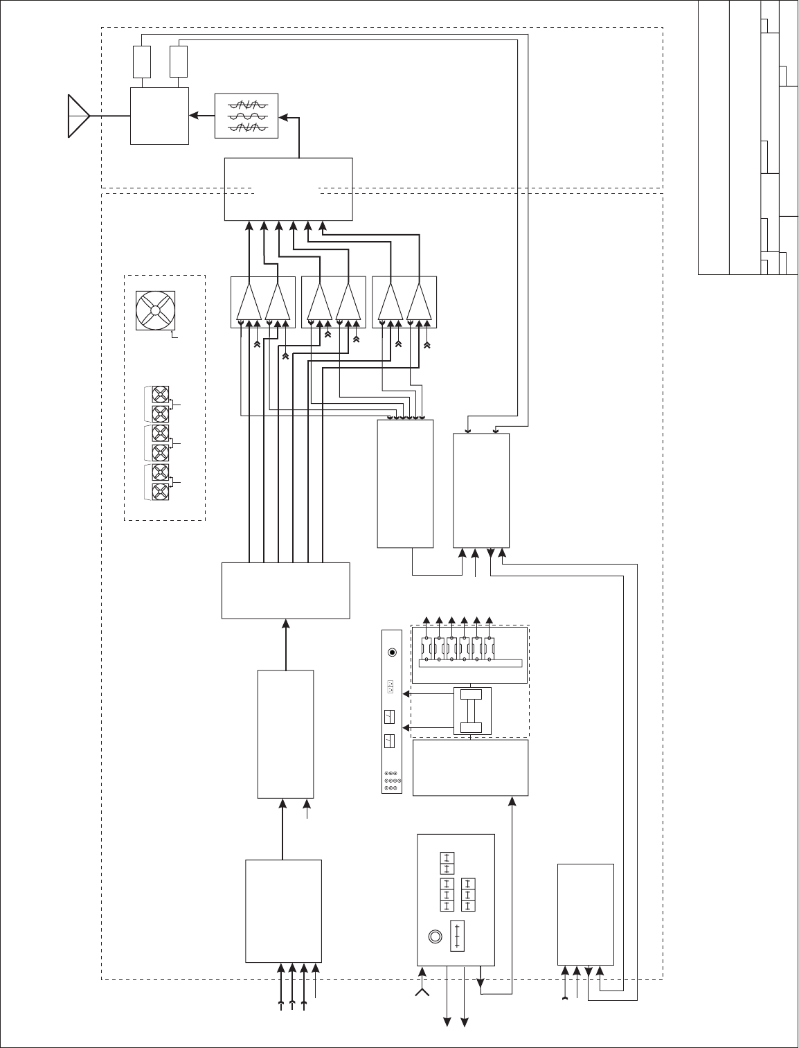
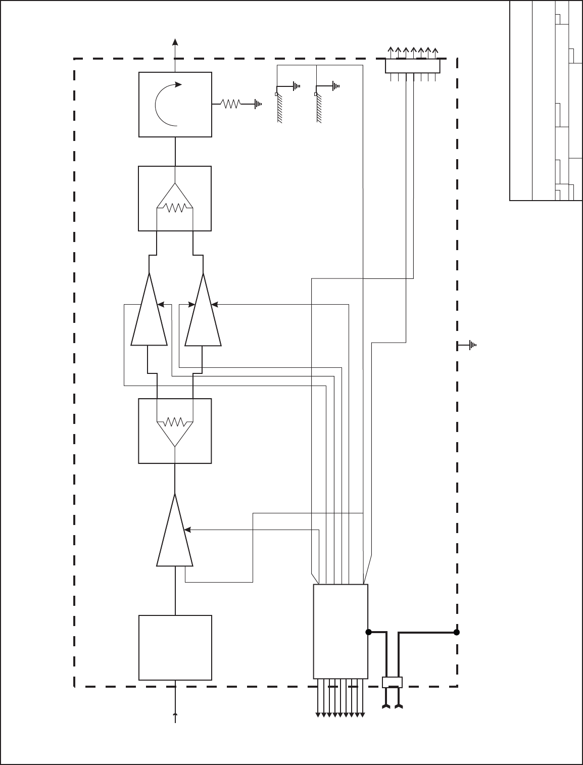
Refer to the UTX5K ULTRA-2 block diagram for an overview of the transmitter architecture. This will give
the technician basic information needed to understand the operation of the transmitter and the function
of each subassembly.
SEE SECTION Vl.A FOR PARTS LIST AND BLOCK DIAGRAM.
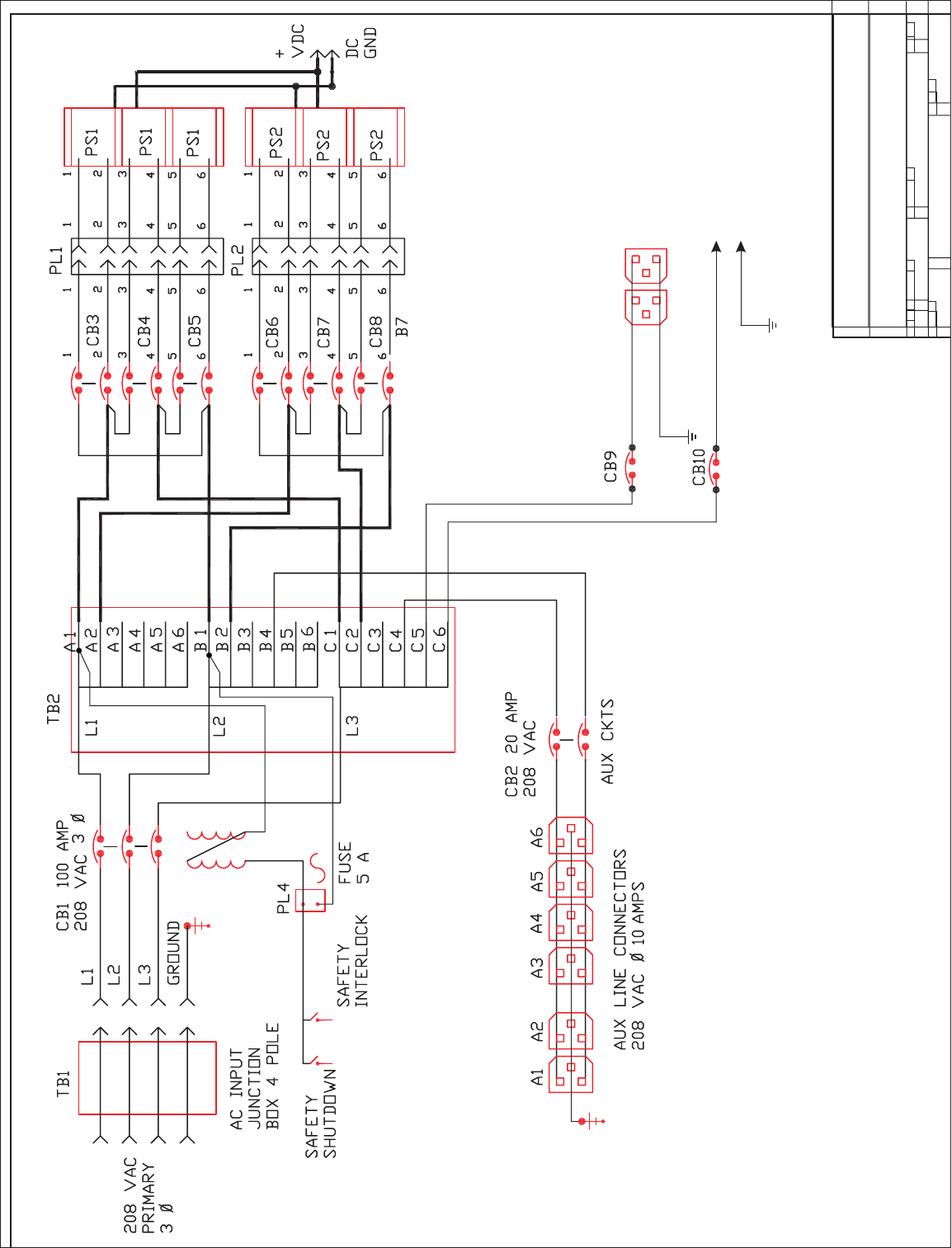
B. ADCIS5 AC DISTRIBUTION
The
A
CDIS5 is the primary AC power inlet for the transmitter. The UTX5K ULTRA-2 transmitter was designed
for Standard 208 to 230 VAC 3-Phase using a FIVE (5) wire connection. The transmitter can be Optionally
powered as 220 to 240 VAC Single Phase using a four (4) wire connection.
Standard Optional
--- 3 wires for 208 - 240 VAC 3 Phas
e
--- 2 wires for 220 -240 VAC Single Phase
--- 1 wire for neutral connection --- 1 wire for neutral connection
--- 1 wire for safety ground connectio
n
--- 1 wire for safety ground connection
CAUTION: Connection to the AC Primary source must be made using all five wires listed above. Follow
the wiring instruction given in TRANSMITTER INSTALLATION Section lll.3. If not followed, severe damage to
the transmitter and, or, electrical shock could result.
The
A
CDIS5 performs the following functions:
1. Provides a primary AC power breaker point to shutdown the transmitter.
2. Provides 208 VAC power to each of the 2.2KW DC power supplies with individual breaker points for
added safety.
3. Provides 110 VAC circuits for Modulator,
A
DP500, ABS (as necessary) and
A
UX Power where
needed.
SEE SECTION Vl.B FOR SCHEMATIC AND PARTS LIS
T
C. PS12KW POWER SUPPLY
The UTX5K ULTRA-2 transmitter is designed with over 12 KW of DC power. To achieve this level, the modules
mounted in the power supply in the transmitter rack consist of six (6) AC2008 power units with two (2)
A
C2009 main frame assemblies each of which are capable of managing three (3) 2 KW modules each.
The power modules are "HOT PLUGGABLE" and can be removed or installed without turning off the
transmitter.
Each power supply module has OVER VOLTAGE, OVER CURRENT AND OVER TEMPERATURE
protection as well as a fault signal in the event of a failure.
REFER TO MANUFACTURER'S MANUAL FOR MODEL # TWRI6004 PROVIDED WITH THE UTX5K ULTRA-2.
Page 8

PINEAPPLE TECHNOLOGY, INC.
UTX5K ULTRA-2 Operating and Service Manual V -- THEORY OF OPERATION
(CONTINUED) Page 2 of 5
D. ADP500 AND PAS6 PERFORMANCE MONITO
R
The ADP500 and PAS6 Performance Monitor provides the following functions:
1. Monitors FORWARD AND REFLECTED POWER to the hybrid combiner and presents it as a percentage
of power rating. The transmitter comes set to 100% P-Sync power based on the ratings of the transmitter.
2. Provides a HIGH ANTENNA VSWR MONITOR in the event of an antenna or coax failure where
the reflected power exceeds 25% the transmitter will shut down. The front panel LED will change
from green to red in case of a fault.
3. Provides current monitoring of all the pallets used in the six (6) PA1K power amplifier assemblies. The
current levels can be read directly from the multi-meter on the front panel. Individual pallets are
selectable on the ADP500 and the PA assemblies are selected using the PAS6. In normal operation,
a PA FAULT is indicated by going from green to red. RED indicates that the current level is below
500 ma and a transistor could have failed. To read the actual current, select the appropriate PA Bank
using the PAS6. The ADP500 will now display status of each pallet in that PA. The multi-meter will read
the actual current.
4.
A
PA INHIBIT switch is provided for failure diagonostic purposes. When activated, this switch allows
the technician to monitor the bias currents for each pallet. These readings were recorded at the factory
and are found on the Transmitter Test Report, DC Test Report Section. This is the best way to
troubleshoot possible transistor problems. When in the PA INHIBIT mode, the RF PWR OFF LED will
change from green to red indicating that the "SHUTDOWN LINE" is at TTL 0 state and the output power
has been reduced to near zero.
5.
A
n RF MONITOR port (BNC) is available to connect a spectrum analyzer for monitoring the
output signal.
6. METER SELECTION SWITCHES
The PAS6 is used to select the appropriate PA Module (PA1K) for performance display on the ADP500.
PA designations are PA1 starting from the top row going left to right with PA6 located on the bottom (3rd)
row down on the right side when viewed from the front of the transmitter rack.
The rotary switch on the ADP500 is the detail selector for the multi-meter. The various positons are
defined as follows:
PA1 thru PA5…………………………………
…
Reads PA Pallet currents as selected
Typical reading in INHIBIT MODE 1.5 to 2.5 A
Typical reading SMPTE BARS 5-7 A for PA1 thru PA4
Typical reading SMPTE BARS 2-3 A for PA5
PA6……………………………………………
…
No Connection
PS VOLTS……………………………………
…
Reads DC voltage applied to PA stages
Typical reading would be +29 to 33 VDC
P FWRD………………………………………
…
Reads PA output power in P-Sync percentage of rating
Full power reading would be 100%
Page 9

PINEAPPLE TECHNOLOGY, INC.
UTX5K ULTRA-2 Operating and Service Manual V -- THEORY OF OPERATION
(CONTINUED) Page 3 of 5
7. METER SELECTION SWITCHES
P RFLD………………………………………
…
Reads PA output power being returned from the load and
displayed as a percentage of forward power. Typical
reading would be < 5% indicated.
P AURAL……………………………………… Reads the AURAL POWER component as a percentage
of forward power. Typical reading would be 5%
A
UX 1 & AUX 2………………………………
…
Not used in this configuration.
E. RC8 REMOTE MONITOR AND CONTROL WITH ABS
This equipment is OPTIONAL and can be used to satisfy FCC remote control requirements.
The Remote Monitor is used to monitor the operational status of the transmitter and will allow the
operator to turn RF on or off and adjust power levels remotely. The following items are monitored or
controlled:
1. Transmitter on/off function
2. Power output level monitor and adjust
3.
A
C Line Voltage status - With ABS you can be notified if there is a power failure at the site.
4. Various other custom options are available. Specify these at the time the transmitter is
purchased and they will be included if possible.
Remote monitoring requires a phone line connection. Information can be accessed via a PC Terminal.
The Auxiliary power unit requires a battery connection. A common car battery (12 VDC) can be used
with a charger as an ABS. This will run the Monitor and provide access to transmitter status for several
hours.
A
manual for this equipment is provided by the Manufacturer and is included in the UTX5K ULTRA
package shipped with the transmitter. The manual is only included if this option was purchased for
delivery with the transmitter.
REFER TO INSTRUCTION MANUAL PROVIDED WITH THIS PACKAGE.
F. MA2000 MODULATO
R
The heart of any TV Transmitter is the MODULATOR. This equipment receives the video and audio
signals was well as any control signals needed. The base band signals are converted to RF with an
output on the desired operating channel.
Detail operation of the Modulator with schematics and parts list are provided by the equipment
manufacturer and included in the UTX5K ULTRA-2 package shipped with the transmitter.
REFER TO INSTRUCTION MANUAL PROVIDED WITH THIS PACKAGE.
Page 10

PINEAPPLE TECHNOLOGY, INC.
UTX5K ULTRA-2 Operating and Service Manual V -- THEORY OF OPERATION
(CONTINUED) Page 4 of 5
G. UDR100AC 100 WATT DRIVER AMPLIFIER
The RF output from the MA2000 Modulator is applied to the input of the UDR100AC driver amplifier.
This amplifier increases the drive level to that required for each of the six (6) PA1K power
amplifiers to make rated power. The UDR100AC is powered by 110 VAC.
REFER TO SECTION Vl.C. FOR SCHEMATIC DIAGRAM AND PARTS LIST
.
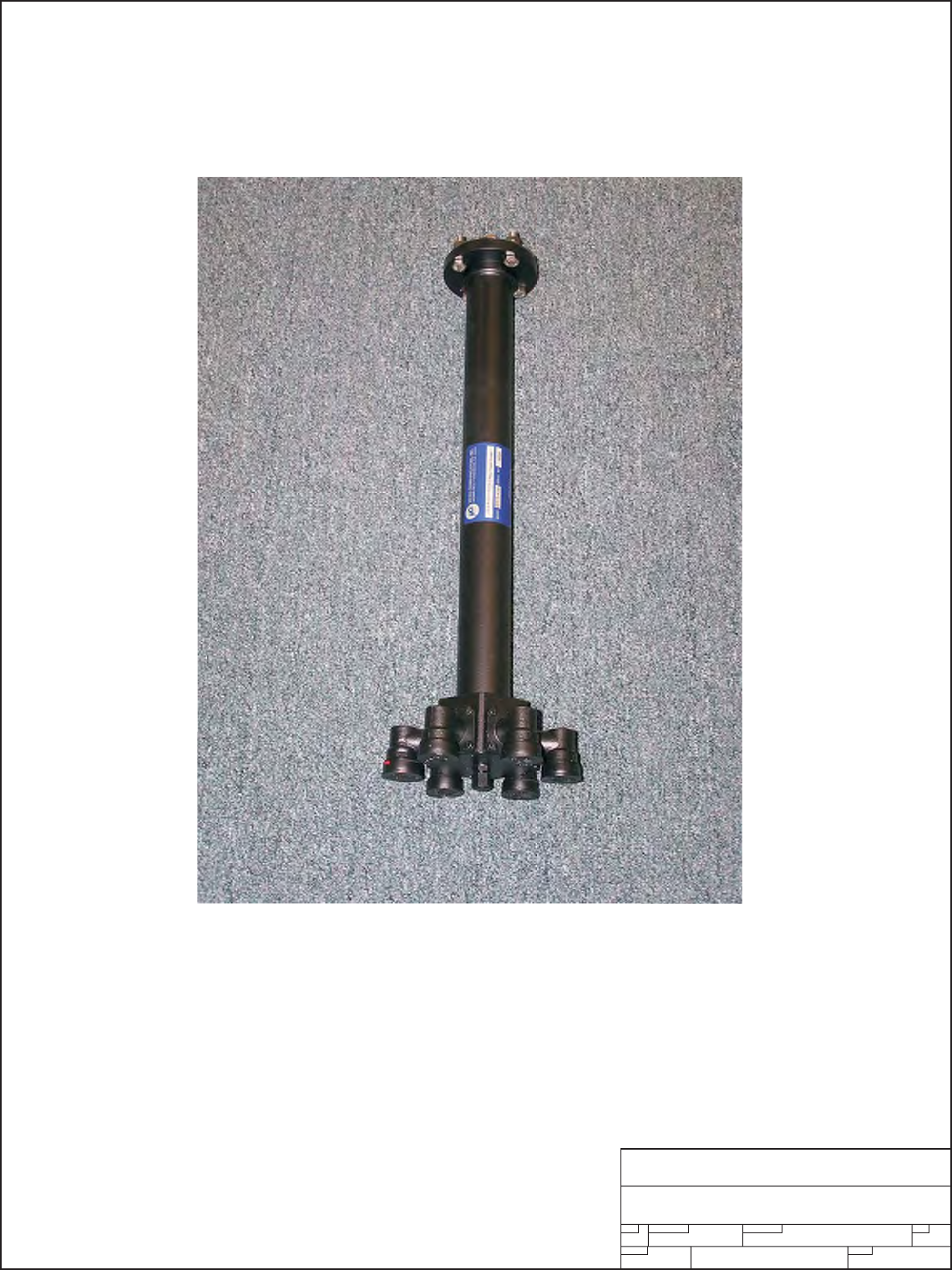
H. S6 6-WAY SPLITTER
The S6 Splitter is an 6-Way in-phase broadband splitter. This splitter provides an equal split of drive
power to each of the six (6) PA1K power amplifiers in each transmitter rack.
SEE SECTION Vl.G. FOR PARTS LIS
T
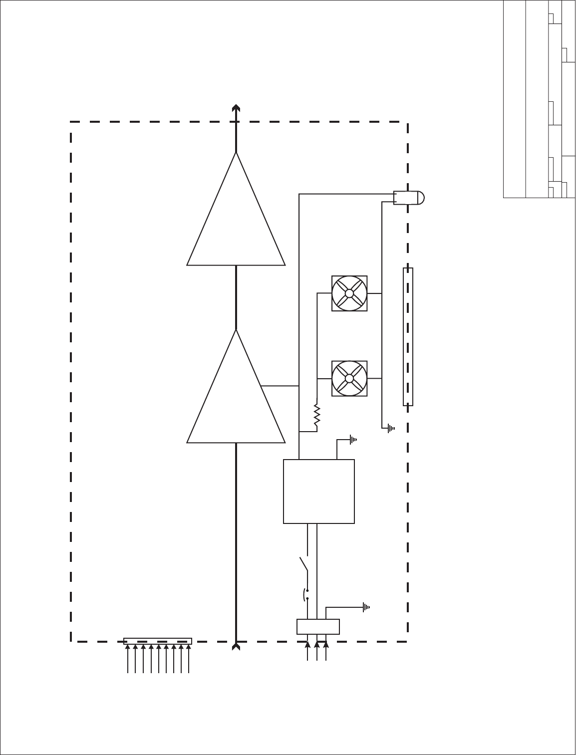
I. MFA2PA POWER AMPLIFIER HOUSING
The MFA2PA is the main RF Power Amplifier housing which accommodates two (2) PA1K Amplifiers.
The housing includes the following:
2 each 330 CFM cooling fans
2 each
A
ir filter assemblies
2 each Front panel status PC boards
1 each Main chassis
2 each Mechanical slide assemblies
1 each
A
C Filtered inle for cooling fans
SEE SECTION Vl.D FOR SCHEMATICS AND PARTS LIS
T
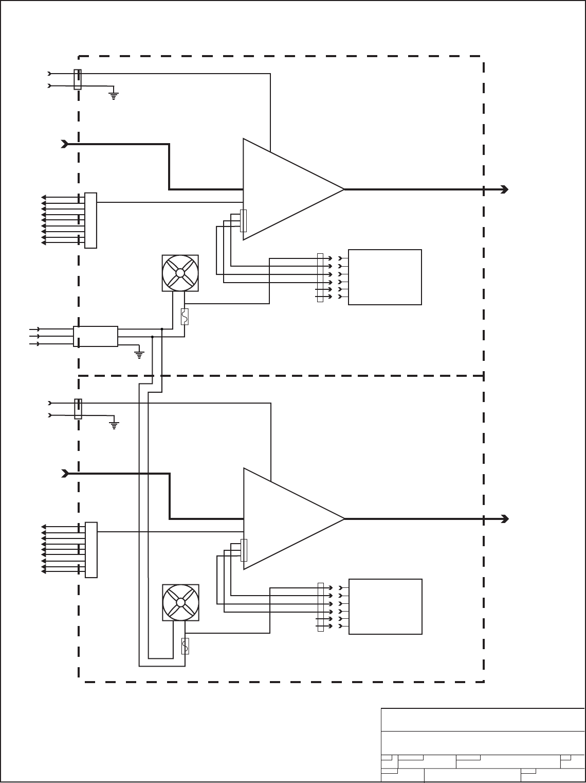
I-1. PA1K POWER AMPLIFIER
The PA1K is the main RF Power Amplifier Assembly used in the UTX5K ULTRA.
Each amplifier assembly is made up of one (1) U250LD power pallet and two (2) U500LDA power
pallets. These amplifiers are operated in Class A/AB or sometimes referred to as "HARD AB". This
refers to the bias levels to achieve best linerarity.
Each PA1K amplifier assembly includes the following:
1 each U250LD power pallets
2 each U500LDA power pallets
1 each Phase and gain matching circuit
1 each 2-Way in-phase splitter
1 each 2-Way in-phase combiner
1 each Circulator
1 each Power distribution module (1A0025)
2 each Thermal sensors
1 each Remote monitor port (DB9)
1 each Front panel status port (Molex)
1 each Filtered DC input port
1 each Type N Panel mounted RF Input port
1each DIN 7/16 Panel mounted RF Output port
SEE SECTION Vl.E. FOR SCHEMATICS AND PARTS LIST
Page 11

PINEAPPLE TECHNOLOGY, INC.
UTX5K ULTRA-2 Operating and Service Manual V -- THEORY OF OPERATION
(CONTINUED) Page 5 of 5
J. UC6KWN 6-WAY COMBINER
The UC6KW is an 6-Way in-phase combiner. The combiners are specifically designed
for the channel designated transmitter frequency. This is a closed unit and cannot be serviced.
SEE SECTION Vl.G. FOR PARTS LIS
T
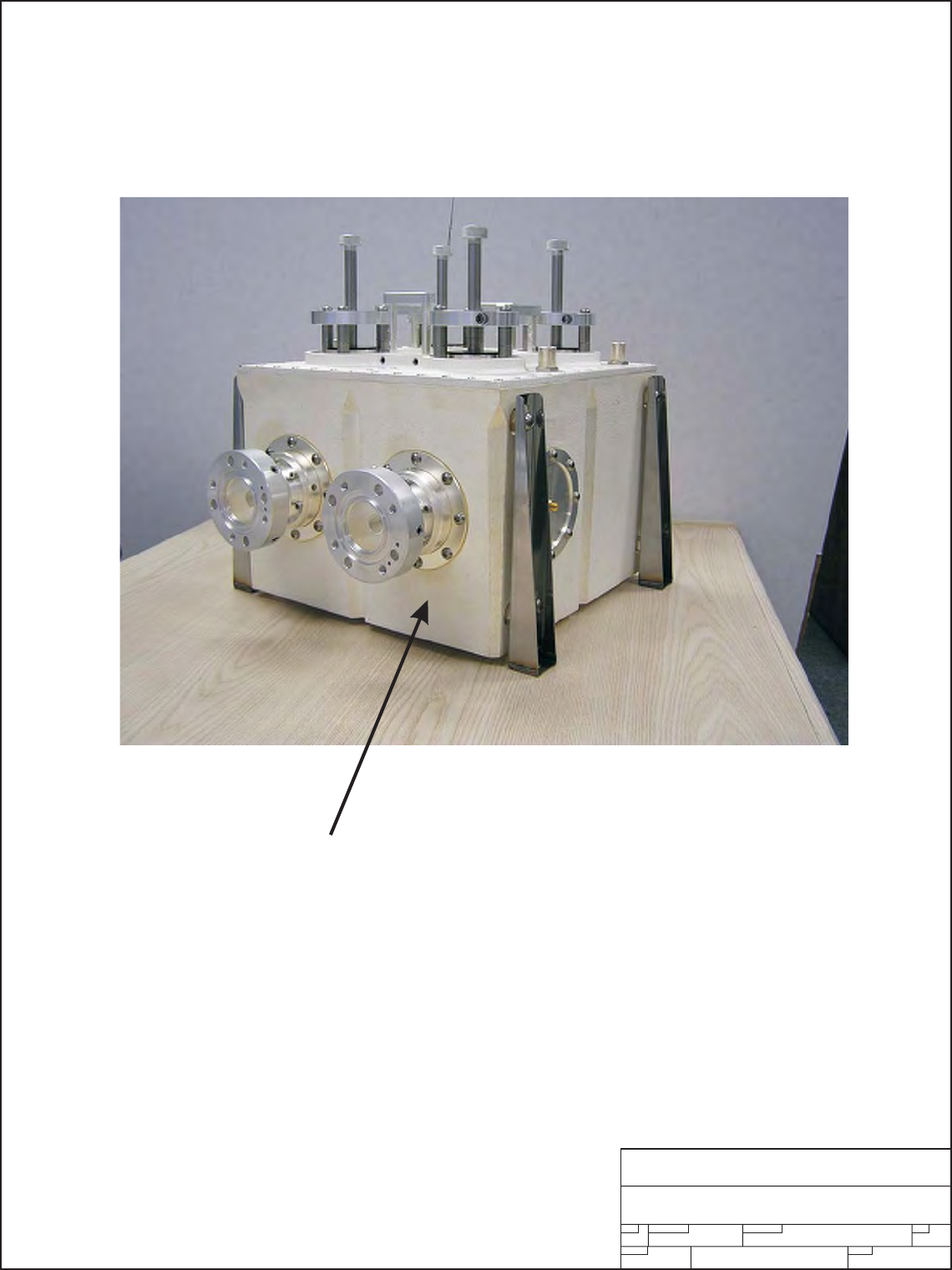
K. BPU10K UHF BAND PASS FILTER
This Band Pass filter was designed to meet FCC Certification requirements with minimum loss of
RF Power. The BPU10KW comes tuned and tested to the operating frequency of the transmitter
and should no be adjusted without proper equipment. Replacement filters are available as
P/N BPUKW UHF (+CHANNEL NUMBER).
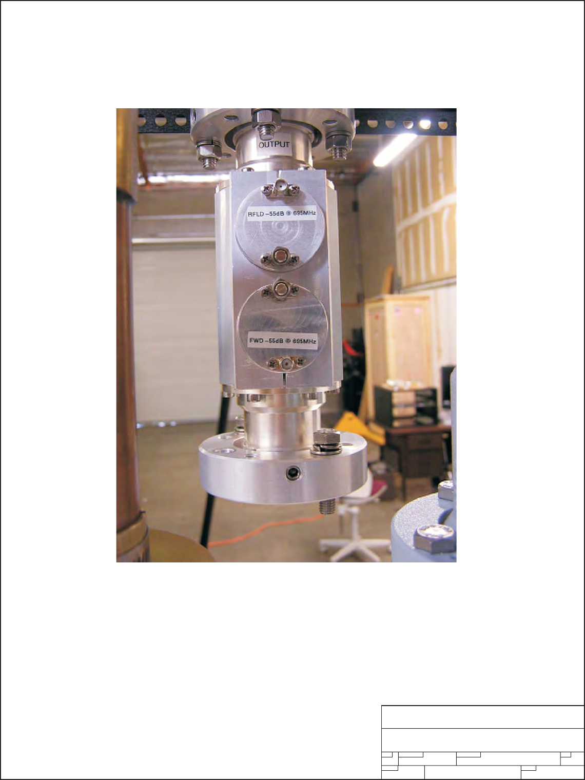
L. DC7KW DIRECTIONAL COUPLER
The DC7KW Directional Coupler provides for insertion monitoring of forward and reflected RF
power, between the output combiner and the bandpass filter, and is sent to the ADP500 for display.
M. AUX MONITOR PANE
L
The auxiliary monitor panel provides analog meter measurements for the primary DC supply. The
total power supply current and voltage are displayed on these meters. These measurements serve
as a good indication of the operation of the transmitter final power amplifiers.
Each power supply has a current monitor output. These outputs are accessible on the AUX5 front
panel. Each (PS I Share) test point will indicate a relative amount of current being supplied from the
power supply. This is not a calibrated or accurate measurement that is scaled from the current
capability of the power supply. This is also a second-level diagnostic tool for use by qualified
technicians.
In the event of an EMERGENCY, a SHUTDOWN SWITCH located on the AUX5 will shut down the
transmitter and remove all power starting from the MAIN 3-P BREAKER. To turn the transmitter
on, it is necessary to RECYCLE the SHUTDOWN SWITCH before the transmitter MAIN BREAKER
can be turned on.
N. FP6 FUSE AND SHUNT PANEL
The FP6 serves as a DC SUMMING POINT for all current coming from the power supplies. After being
summed, the current passes through a 1000 AMP precision shunt which is used for measuring the total
supply current and voltage being applied to the transmitter power amplifiers. At this point, the DC power
is distributed to each PA1K amplifier assembly through a series 125 amp fuse.
NOTICE: BEFORE ANY SERVICE WORK IS PERFORMED ON THE FP6 ALL POWER TO THE
TRANSMITTER MUST BE TURNED OFF FOR SAFETY.
Page 12

Section VI
Schematic
and
Parts List

PINEAPPLE TECHNOLOGY, INC.
UTX5K ULTRA-2 Operating and Service Manual Vl -- SCHEMATICS AND PARTS LIST
A. UTX5K ULTRA Assembly Tre
e
Item Qty Type P/N Title Detail
Top CAT UTX5K-2 ULTRA NTSC XMTR 5KW P-SYNC 470-810 MHz 1EA 6FT DEEP RACK
1 1 PL BPU10K BP FILTER UHF TV 10 KW P-SYNC RATING
2 2 PS AC8100
A
C WIREMOLD 120 VAC 19 IN
RACK MTG 1 X 4 OUTLETS 6 FT CORD
3 2 PS AC8220 AC WIRE MOLD 220 VAC 19 IN RACK MT
4 1 PS 851026 FAN AC 208 2000 CFM EXHAUSE MULTIFAN VOSTERMANS 4VF1042A
7 1 CAT ADP500 DISPLAY PANEL, ANALOG SEL SW AND METER
8 1 CAT AUX AUX PANEL 5KW USED ON 3, 4, 5 KW XMTRS
9 1 PL ACDIS5 AC DISTRIBUTION PANEL 3-PHASE SPLIT OUT
10 1 CAT PAS6 PA SEL SW FOR ADP500 6 POSITIONS W/1 OUTPUT
12 3 PL MFA2PA 2KW MAIN FRAME W/U500LD AMPS UHF/VHF ASSEMBLIES
13 2 PS MFR44RU 44 RU ASSEMBLIED RACK MIDDLE ATLANTIC MRK-4442
14 1 PS UC6KWN 6-WAY COMBINER UN-ISOLATED 3 1/8 EIA OUTPUT W/7/16 DIN INPUT
15 1 PL PS12KW 12KW POWER SUPPLY COMBO
16 6 PS 1A7052 CABLE ASSEMBLY RG-223 BNC-M TO N-M 52 INCHES LONG
17 6 PS PAC0005 DB9 MALE TO MALE 6 FT LONG PA MONITOR CABLE
18 1 PL 1A6006 DC CABLE SET 5KW HIGH CURRENT ASSEMBLY
19 2 PS MF9554A EXHAUSE FAN SHROUD OUTLET SIDE PANEL
20 2 PS MF9555A EXHAUST FAN OUTLET SIDE PANEL
21 1 PS MF9556A EXHAUST FAN FINGER GUARD
22 1 CAT UDR100AC
UHF DRIVER AMP 100W W/AC
SUPPLY U250LD AND UDR100 AMPS
23 4 PS MFR44RU-ZRA Z RAILS MIDDLE ATLANTIC MV-ZRA-44
24 1 PS MFR44RU-SPN SIDE PANELS FOR RACK MIDDLE ATLANTIC SPN-44-423
25 1 PS MFR44RU-BB GROUNDING BAR CU MIDDLE ATLANTIC BB-44-1
26 60 PS INHOUSE_LABOR PTI LABOR LOADED
27 40 PS INHOUSE-ENG TE
S
ENG TESTING AND FIXIT LOADED
28 6 PL 1A7065 CABLE ASSEMBLY LDF4-50 UTX SERIES XMTR 7/16 DIN TO N M
29 2 PS MF-RU1 19 INCH 1 RU FRONT PANEL PAINTED
30 1 PS MF-RU2 19 INCH 2 RU FRONT PANEL PAINTED
31 1 CAT FP-6 FUSE PANEL UTX3KWA INC FUSE, SHUNT, SHIELD
32 1 PS RC8 REMOTE CONTROL 8 CHANNEL MINIMAC 01 COM-LABS
33 1 CAT MA2000 MODULATOR, TEKNOLIGIX
34 1 PS DC7KW DIRECTIONAL COUPLER 7.5 KW 2 PROBES FWRD/RFLD 1/58 EIA FLG
35 1 PL S6 6-WAY INPHASE SPLITTER PHASE AND GAIN ADJUSTMENTS
36 8 PS MF9283 EQUIPMENT SUPPORT 14 GA GAL-XC (LEFT & RIGHT)
37 1 PS AC8055
AC BARRIER TERMINAL BLOCK 5
POLE BUSSMAN 14002-5
Page 13
SIZE FSCM NO.
SCALE SHEET
DWG NO. REV
Pineapple Technology, Inc.
Rocklin, CA
UTX5K ULTRA-2
BLOCK DIAGRAM
1of1
1
B
FIT
Mod & Driver
MA2000 BPU10K
Bandpass
Filter
Combiner
6-Way
UC6KWN
Splitter
6-Way
S6
100 W Driver
UDR100AC
ADP500
PAS6
Po Level
Xmtr On/Off
Aural
Remote
Control
(Opt)
RC8
Phone Line
Xmtr On/Off
Po Level
+12 VDC
Visual
IF
RF Output
AC Inlet AC Inlet
AC Inlet
Fwrd Pwr
Rfld Pwr
AA
B
CAL
ATT
CAL
ATT
RF
DC Distribution Panel
Emergency
Shutdown
DC Amps
DC Volts
Main AC
Breaker
AC Main Distribution
ACDIS4
208 VAC
3-Phase
208 VAC 3P
110 VAC
208 VAC 1P
A
AC
Inlet
AC Inlet
DC Output
A
D
PA5
M
+DC
RF IN
MFA2PA
PA6
M
+DC
RF IN
MFA2PA
PA4
M
+DC
RF IN
PA3
M
+DC
RF IN
MFA2PA
PA1
M
+DC
RF IN
PA2
M
+DC
RF IN
+32VDC
+32VDC
+32VDC
+32VDC
+32VDC
+32VDC
+32 VDC
To PA1
To PA2
To PA3
To PA4
To PA5
To PA6
MFA2PA MFA2PA MFA2PA
PA1 PA2 PA3 PA4 PA5 PA6
Rack A Fan
D
DDD
PA Fans
125A
125A
125A
125A
125A
125A
AUX
PS12KW
12 KW
Power
Supply
100 mv FS
Meter
Shunt
FP6
DC7.5KW
Directional
Coupler
Rack A Rack B
Page 14

PINEAPPLE TECHNOLOGY, INC.
UTX5K ULTRA-2 Operating and Service Manual
V
l -- SCHEMATICS AND PARTS LIS
T
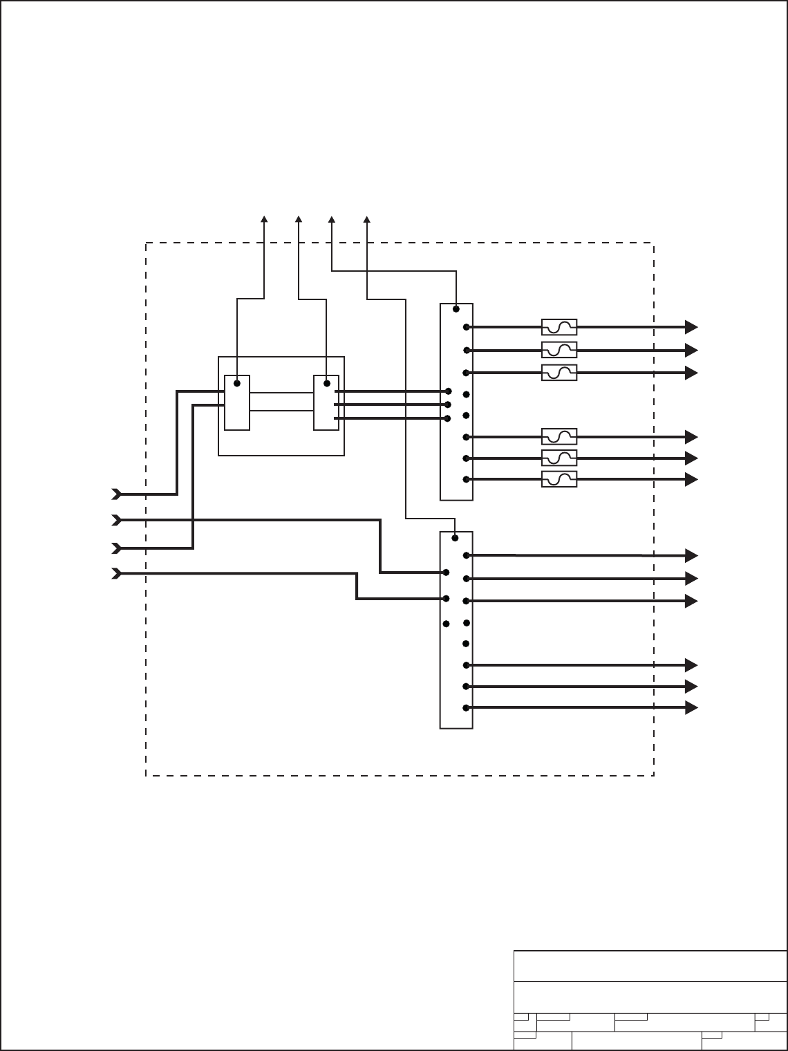
B. ACDIS4 AC Distribution --- PARTS LIS
T
Item Qty Type P/N Title Detail
Top PL ACDIS4 AC DISTRIBUTION PANEL 3-PHASE POWER SPLIT OUT
1 1 PS MF9287B ACDIS3, 4, AND 5 CHASSIS
2 1 PS MF9288A TOP, COVER BREAKER PANEL
3 2 PS AC4120 AC POWER SOCKET 7 PIN BULGIN PX093/07/S
4 2 PS AC4110 AC POWER PLUG 7 PIN BULGIN PXA911/07/P
5 1 PS 630001 INDICATOR LITE RED 220 VAC 1/2W
6 1 PS AC8100
AC WIREMOLD 120 VAC 19 IN
RACK MTG 1 X 4 OUTLETS 6 FT CORD
7 1 PS 460300 HW FUSE CLIP LITTELFUSE H111505
8 1 PS 480470 MOLEX PLUG STR 3 PIN MOLEX 39-01-4032-P
9 1 PS AC3120 AC CKT BRKR 20 AMP SINGLE POLE
10 1 PS AC32100 AC BKR 3-PHASE 100 AMP W/TRIP COIL
11 7 PS AC3220 AC CKT BRKR 20 AMP 2-POLE 22O V
12 1 PS AC4200 AC DUPLEX OUTLET 110 VAC 15 A BLACK
13 1 PS AC5105 AC PANEL MTG OUTLET 4 POSITION "GANGED" 15A 115VAC
14 1 PS MF9289 PLATE, AC LINE CONNECTORS
15 1 PS MF9558A ACDIS5 AUX PANEL
16 1 PS MF9318 FRONT PANEL ACDIS4 AC DISTRIBUTION FOR UTX5KW ULTRA
Page 15
SIZE FSCM NO.
SCALE SHEET
DWG NO.REV
Pineapple Technology, Inc.
Rocklin, CA
ACDIS4
AC Distribution Panel
1of1
4
B
FIT
SECTION VI--SCHEMATICS AND PARTS
SECTION VI--SCHEMATICS AND PARTS
SIZE FSCM NO.
SCALE SHEET
DWG NO. REV
Pineapple Technology, Inc.
Rocklin, CA
ACDIS4
AC Distribution Panel
32
1of1
4
B
FIT
A
A
B
B
C
C
1
SECTION VI--SCHEMATICS AND PARTSSECTION VI--SCHEMATICS AND PARTS
(UTX5K ULTRA() VERSION)(UTX5K ULTRA() VERSION)
AUX PANEL
RECEPTICALS
AUX PANEL
RECEPTICALS
MA2000
110VAC
Power
Strip
110VAC
Power
Strip
UDR100AC
ADP500
UDR100AC
ADP500
110 VAC110 VAC
110 VAC110 VAC
}
Page 16

PINEAPPLE TECHNOLOGY, INC.
UTX5K ULTRA-2 Operating and Service Manual Vl -- SCHEMATICS AND PARTS LIST
C. UDR100AC Assy Tre
e
Item Qty Type P/N Title Detail
Top CAT UDR100AC
UHF DRIVER AMP 100W W/AC
SUPPLY U250LD AND UDR100 AMPS
1 1 CAT U250LD UHF TV 250 W P-SYNC PALLET 470-810 MHz ZINGER COMBINER
2 1 CAT UDR25A DRIVER, 25W LINEAR 470-815 MHz LDMOS DUAL PACKS PALLET MTG
3 1 PS MF9337B PANEL, FRONT DRV100DC
4 1 PS MF9338F CHASSIS DRV100-3
5 1 PS MF9339B DIVIDER AIR FLOW DRV100DC
6 1 PS MF9340B TOP COVER DRV100DC
7 1 PS MF9341 DRV100 HEAT SINK ALL DRV TYPES
8 2 PS 851005 FAN DC 24 V 80X25mm COMAIR-ROTRON
9 2 PS 990201 FILTER & FINGER GUARD 80X25mm FAN 30 PPI
10 1 PS 631001 INDICATOR LAMP LED GREEN 24 VDC 1/2 IN MTG HOLE
11 1 PS 484001 SW, ON/OFF ROCKER AC CW IND. NAA-211-B121-00
12 1 PS AC1003 FILTER, AC LINE 110/220 AC PLUG
13 1 PS AC3110 AC CKT BREAKER 115 VAC 10 AMPS RS TYPE
14 1 PS 451004 HW TER BLOCK #6 2X6 ROW
15 5 PS 451010 TERM BLOCK JUMPERS 2 POLE
16 1 PS AC2010 DC POWER SUPPLY 115/220 VAC 320 WATTS 27-31 VDC
17 2 PS CC316-NPF-PT-21 CABLE ASSEMBLY RG316/ 1 N-FM PANEL MT WITH PIGTAIL
18 1 PS 481100 CON 9 P D-SUB MALE MALE 9P SOLDER CUP
19 1 PS 140010 RES 2W 10 OHM 10 OHM
20 1 PS 140012 RES AXIAL TH 2 WATT 75 OHM METAL OXIDE
Page 17
SIZE FSCM NO.
SCALE SHEET
DWG NO.REV
Pineapple Technology, Inc.
Rocklin, CA
UDR100AC AMP/DRIVER
BLOCK DIAGRAM
U250LD
UDR25A
GND
75 OHM
DC FANS
LAMP
RF IN RF OUT
Air Inlet Filters
A
1:1 1of1
P1
P2
P3
P4
P5
P6
P7
P8
P9
Optional
Remote
Interface
DB9
110 VAC {DC
Power
Supply
+28 VDC
Filter
CB On/Off Sw
SECTION VI-PARTS AND VENDORS
SUB-SECTION C-UTX5K ULTRA-2
Page 18

PINEAPPLE TECHNOLOGY, INC.
UTX5K ULTRA-2 Operating and Service Manual
V
l -- SCHEMATICS AND PARTS LIS
T
D. MFA2PA POWER AMPLIFIER -- PARTS LIS
T
Item Qty Type P/N Title Detail
Top PL MFA2PA 2KW MAIN FRAME W/U500LD A
M
UHF/VHF ASSEMBLIES
1 1 PS MF9100E MAIN CHASSIS MFA1KW
2 1 PS MF9101D DIVIDER, PLENUM MFA1KW
3 1 PS MF9102C DIVIDER, FAN MFA1KW
5 1 PS MF9104B COVER, TOP MFA1KW
10 4 PS MF9139 SLED GUIDE U600LP & MFA1KW
11 1 PS MF9123D FRONT PANEL, PAINTED MFA1KW
14 2 PS 990199 FILTER, AIR DRY FF-5 MFA/PS FP
16 2 PS MF9127 MTG BRACKET, MOLEX FMALE MFA1KW
17 6 PS 480472 MOLEX CRIMP TERM MFA1KW MOLEX MFG 39-00-0041
18 2 PS 480400 MOLEX PLUG 6 TERM MFA1KW MOLEX 15-06-0065 MINI-FIT BMI
19 2 PS 460150 FUSE HOLDER PANEL MTG 3AG TYPE QC CON
20 2 PL 1A0035 PA STATUS BOARD PC9061H
22 4 PS INHOUSE_LABOR PTI LABOR
24 2 PS MF9308 FAN FINGER GUARD MFA1KW & U600LPA
25 2 PS MF9310 AC FAN INLET HOLDER MFA1KW
27 2 PS MF9258 BRACKET FILTER MTG PAINTE
D
U600LPA & MFA1KW
28 1 PS MF9197B DIVIDER PA MFA1KW
29 2 PS 851025 FAN, AC 220 V COMAIR ROTRON TN3A2
30 2 PS AC5110 AC FAN PLUG & CORD FMALE PLUG 24 IN CORD
31 2 PS 451080 TERM BLOCK EU STYLE 4 POLE 12-24 GAGE
32 0.1 PS H-TAPE_TFE TEFLON TAPE, SLIDES 1 INCH X 56 INCHS
33 2 PL PA1K UHF 1KW PA ASSEMBLY U500L
D
DIN OUTPUT W/CAPTOR FILTERS
Page 19
PA1K
PA1K
DB9
DB9
P1
P1
L1
L2
GND
220 VAC
PA1A
PA1A
GND
GND
PA5
PA5
PA2A
PA2A
PA1B
PA1B
SD
SD
+VDC
+VDC
PA2B
PA2B
P6
P6
P5
P5
NA
NA
P8
P8
P9
P9
P7
P7
P4
P4
P3
P3
P2
P2
3A
Fuse
3A
Fuse
J5
J5
220 AC Fan
330 CFM
220 AC Fan
330 CFM
Filter
P3
P3
J3
J3
Fan Power
Fan Power
Ground
Ground
HS Mon
HS Mon
+28 VDC
+28 VDC
Status Display
Assy
Status Display
Assy
1A0035
1A0035
RF IN
RF IN
RF OUT
RF OUT
J1
J1
+32 VDC
+32 VDC
GND RTN
GND RTN
SIZE FSCM NO.
SCALE SHEET
DWG NO. REV
Pineapple Technology, Inc.
Rocklin, CA
MFA2PA
BLOCK DIAGRAM
PA1, PA3, PA5
PA2, PA4, PA6
MFA2PA ASSY
1of1
FIT
BA
SECTION VI - SCHEMATICS AND PARTS
SUB-SECTION D - UTX5K ULTRA-2
(UTX5K ULTRA-2 VERSION)
Page 20

PINEAPPLE TECHNOLOGY, INC.
UTX5K ULTRA-2 Operating and Service Manual
V
l -- SCHEMATICS AND PARTS LIS
T
D. MFA2PA POWER AMPLIFIE
R
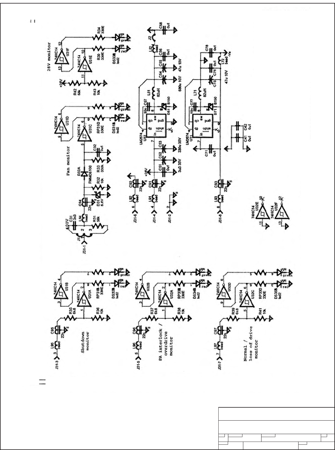
1. 1A0035 STATUS BOARD PARTS LIS
T
Item Qty Type P/N Title Detail
Top PL 1A0035 PA STATUS BOARD PC9061H
1 2 PS 114330 RES ARRAY, SMT 330 OHMS
2 5 PS 115103 RES CHIP 0805 10K OHM SMT 0805
3 1 PS 115334 RES CHIP 0805 330 K OHM SMT
4 1 PS 115563 RES CHIP 0805 56K OHM 0805 SM
5 3 PS 115682 RES CHIP 0805 6.8 K OHM SMT
6 6 PS 21X005 CAP CHIP 0805 100NF 10% XTR 0805 CASE
7 1 PS 21X008 CHIP CAP 0805 10NF 50 V 0805 SM
8 1 PS 240109 CAP TH POLYPROPYLENE 3N3 600 WVDC .033UF
9 1 PS 240110 CAP TAN SMD 3.3 UFD 35 V
10 1 PS 240111 CAP TAN SMD 47 UF 10 V TAN
11 1 PS 241300 CAP RADIAL TH 330 UF 35 VDC
12 1 PS 241301 CAP RADIAL TH 680 UF 10 V ELECTROLYTIC
13 6 PS 27022N FT CAP 22N SM AVX OR MURRATA PART
14 1 PS 480500 CON MICRO-FIT HEADER 3.0 8 PIN PC MTG
15 1 PS 520230 SEMI DIODE SHOTTKEY 1.5 A 60 VDC D-64
16 1 PS 520275 SEMI, DIODE DUAL SW CC 70V SOT-23
17 2 PS 530350 HEX SCHMITH TRIG 74HD14
18 1 PS 538150 IC SWITCHER SIMPLE SO8 PAK
19 5 PS 630200 IND LED DUAL COLOR RED/GREEN T1-3/4 CLR
20 8 PS 750001 FERRITE BEAD SMT 0805 EMI FERRITE BEAD
21 1 PS 830510 IND, W/W 82 UH .58A PWR SMD
22 1 PS PC9061H PA STAUS BRD FR4 060 1/1 CBR
23 2 PS 115331 RES CHIP 0805 33O OHM SMT
24 1 PS 520120 SEMI ZENER 5.6 V MELF
25 1 PS 115683 RES CHIP 0805 68K SM
26 0.2 PS OS_AES_1A0025 OUTSIDE ASS'Y 1A0025 ASS'Y WORK
27 0.1 PS INHOUSE_LABOR PTI LABOR
28 0.1 PS INHOUSE-ENG TES
T
ENG TESTING AND FIXIT
29 1 PS 480510 RECEPTACLE 8 CKT RECEPT MOLEX
30 1 PS 115333 RES CHIP 0805 33K OHM SMT
31 1 PS 1155112 RES 0805 CASE 51.1 K OHM 1%
Page 21
SIZE FSCM NO.
SCALE SHEET
DWG NO. REV
Pineapple Technology, Inc.
Rocklin, CA
1A0035 STATUS BOARD
CIRCUIT DIAGRAM
SECTION VI - SCHEMATICS AND PARTS
SUB-SECTION D.1 - UTX5K ULTRA-2
Page 22

PINEAPPLE TECHNOLOGY, INC.
UTX5K ULTRA-2 Operating and Service Manual
V
l -- SCHEMATICS AND PARTS LIS
T
D. MFA2PA POWER AMPLIFIE
R
2. PA1K ASSEMBLY TREE
Item Qty Type P/N Title Detail
Top PL PA1K
UHF 1KW PA ASSEMBLY U500LD
PAs DIN OUTPUT W/CAPTOR FILTERS
1 1 PL MF9525 HS RT SIDE U500LD ASSEMBLY BLF872 LDMOS
2 1 PL MF9526 HS LEFT SIDE U500LD BLF872 DEVICES
3 1 PL MF9539 ISOLATOR & 2-WAY COMB PLATE U1KWPA ASSEMBLY W/BLF872A
4 2 PL U500LDA 500W 470-810 MHz POWER PALLET RGR 4003 032 MATERIAL BLF872
5 1 PL 1A0025 DC ISO/MONITOR CKT REPLACED CB99
6 1 PS CT-1326A CIR W/TABS CH 26 TO 44 Circulator 542-656 MHz
7 1 PS 270600 FT CAP CAPTOR 9 NF 500V 5/16 TERMINALS
8 1 PS MF9126C MOLEX BRACKET MTG PLATE U600LD ALL
9 1 PS MF9309 REAR PANEL WITH SILK 090 AL ALODYNE
10 1 PS MF9203 B1 1A0025 PCB MTG PLATE SM 09 AL W/MTG
11 1 PS MF9137E SLED U500L AL
12 1 PS 454001 HANDLE, REAR BLK NYLON
13 1 CAT U250LD UHF TV 250 W P-SYNC PALLET 470-810 MHz ZINGER COMBINER
14 1 PS PC9022A_B2 PC BOARD COMB 2-WAY INPHASE 060 1/1 RG
15 1 PL PC9518A
PCB SET OF (3) BRDS OUTPUT
COMB U1KWPA ASS'Y
16 2 PS INHOUSE_LABO
R
PTI LABOR
17 .4 PS
INHOUSE-ENG
TEST ENG TESTING AND FIXIT
18 1 PS CA4000
COAXIAL ASSEMBLY W/7_16 DIN
CON COAX IS SUPPER FLEX
Page 23
SIZE FSCM NO.
SCALE SHEET
DWG NO. REV
Pineapple Technology, Inc.
Rocklin, CA
PA1K Amplifier Assy
BLOCK DIAGRAM
Gain
and
Phase
Network
Power
Distribution
Module
1A0025 Assy
U250LD
PA
RF IN
DB9
J31
RF OUT
U500LDA
PA2
U500LDA
PA1
2-Way Input
Splitter 2-Way In-phase
Combiner Circulator
400 W
50 ohm
Heat Sink L
Heat Sink R
TS2
TS3
+32 VDC
+32 VDC
+32 VDC
A
A
B
B
+32 VDC
+32 VDC
+32 VDC
GROUND
Shutdown Line (SD)
P1 PA1B
P6 PA1A
P5 SD
P8 +VDC
P9 NC
P7 PA2B
P4 GND
P3 PA5
P2 PA2A
A
MFA2PA
Front
Panel
Interface
J26
J25
J24
J23
J22
J29
FIT 1of1
B
SECTION VI - SCHEMATICS AND PARTS
SUB-SECTION D.2 - UTX5K ULTRA-2
Page 24

PINEAPPLE TECHNOLOGY, INC.
UTX5K ULTRA-2 Operating and Service Manual
V
l -- SCHEMATICS AND PARTS LIS
T
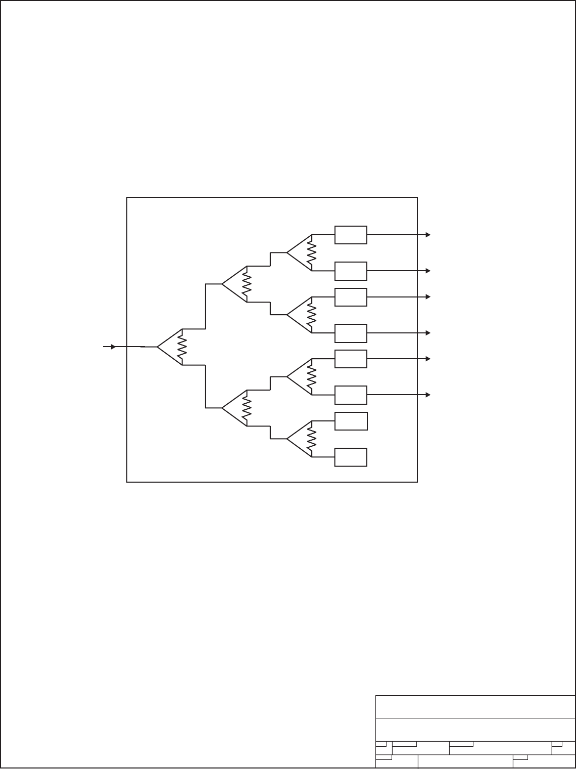
E. S6 6-WAY SPLITTER -- Assy Tre
e
Item Qty Type P/N Title Detail
Top PL S6 6-WAY INPHASE SPLITTER PHASE AND GAIN ADJUSTMENTS
1 1 PS MF9333A FRONT PANEL S10 SPLITTER PAINTED
2 1 PS MF9334A S10 TOP COVER AL 0.063 THK GOLD ALODYNE
3 1 PS MF9335A CHASSIS S10
4 1 PS MF9336A REAR CONN PANEL S10
5 6 PL 1A5003 UHF GAIN/PHASE MTG NETWORK VARIABLE PHASE TUNING
6 1 PS PC9022A_B2 PC BOARD COMB 2-WAY INPHASE 060 1/1 RG
7 2 PS PC9023B PCB COMB/SPLTR R-4003 060 1/1
Page 25
50 Ohm
Term
50 Ohm
Term
G&P
G&P
G&P
G&P
G&P
G&P RF OUT TO PA1
RF OUT TO PA2
RF IN
RF OUT TO PA3
RF OUT TO PA4
RF OUT TO PA5
RF OUT TO PA6
S6 SPLITTER
SIZE FSCM NO.
SCALE SHEET
DWG NO. REV
Pineapple Technology, Inc.
Rocklin, CA
S6 SPLITTER
BLOCK DIAGRAM
SECTION VI - SCHEMATICS AND PARTS
SUB-SECTION E - UTX5K ULTRA-2
Page 26
SIZE FSCM NO.
SCALE SHEET
DWG NO. REV
Pineapple Technology, Inc.
Rocklin, CA
UC6KWN 6-WAY COMBINER
CIRCUIT DIAGRAM
No Serviceable Parts
SECTION VI - SCHEMATIC AND PARTS LISTS
SUB-SECTION F - UTX5K ULTRA-2
Page 27
SIZE FSCM NO.
SCALE SHEET
DWG NO. REV
Pineapple Technology, Inc.
Rocklin, CA
DC7KW Directional Coupler
CIRCUIT DIAGRAM
No Serviceable Parts
SECTION VI - SCHEMATIC AND PARTS LISTS
SUB-SECTION G - UTX5K ULTRA-2
Page 28
SIZE FSCM NO.
SCALE SHEET
DWG NO. REV
Pineapple Technology, Inc.
Rocklin, CA
BPU10KW BANDPASS FILTER
CIRCUIT DIAGRAM
NO SERVICEABLE PARTS
BPU10KW Bandpass Filter
SECTION VI - SCHEMATICS AND PARTS
SUB-SECTION H - UTX5K ULTRA-2
1of1
JC040606
FIT
A
B
Page 29

PINEAPPLE TECHNOLOGY, INC.
UTX5K ULTRA-2 Operating and Service Manual
V
l -- SCHEMATICS AND PARTS LIS
T
I-1 PAS6 SELECTOR SWITCH ASS
Y
Item Qty Type P/N Title Detail
Top CAT PAS10 PA SEL SW FOR ADP500 10 POLE INPUT 1 OUTPUT
1 1 PS PC9501 PA SELECTER SWITCH 10 POLE ADP500
2 1 PS 483010 SW 10 POLE ADP500 PA SELECTOR PAS10
3 1 PS 481250 CON DB9 SUB RT ANGLE FM METAL CASE AMP7457814
4 5 PS 481260 CON DB9 2 SECTION RT ANG PCB MTG 0.9 SPACING
5 1 PS MF9342X1 PLATE, FRONT PAS10 W/ PAINT & SILKSCREEN
6 1 PS MF9343X1 CHASSIS, PAS10 W/ ALODINE & SILKSCREEN
7 1 PS MF9344X1 COVER, TOP PAS10 W/ ALODINE & SILKSCREEN
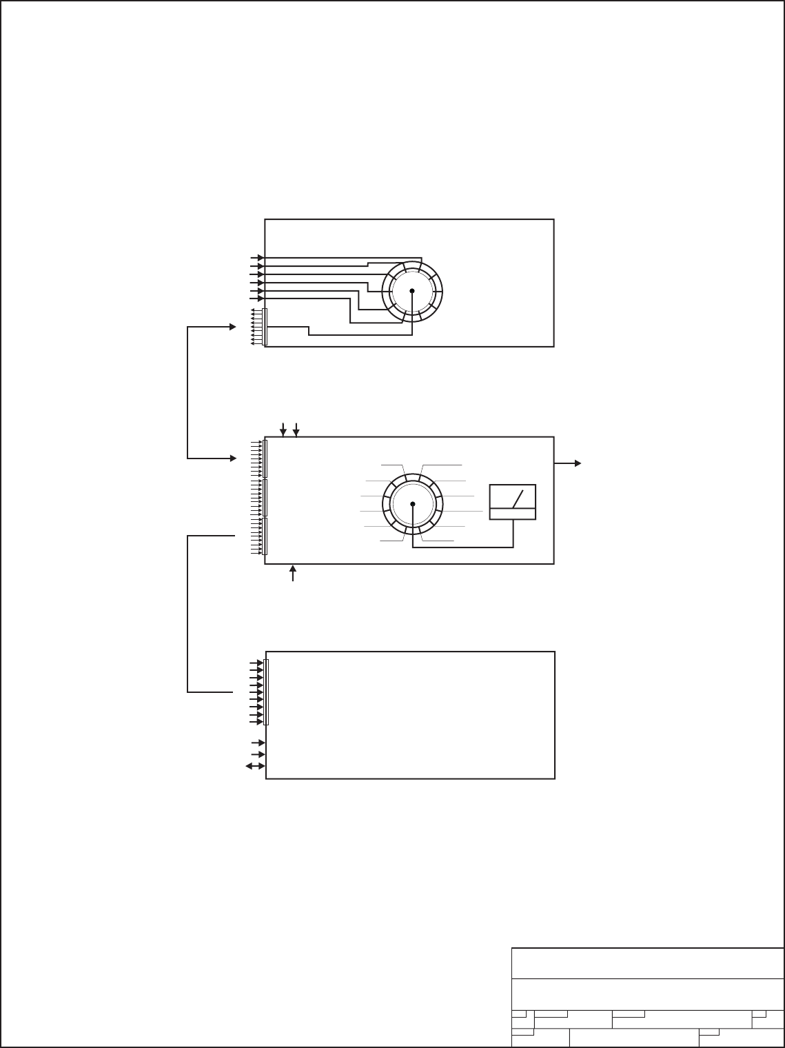
I-2 APD500 PERFORMANCE MONITOR
Item Qty Type P/N Title Detail
Top CAT ADP500 DISPLAY PANEL, ANALOG SEL SW AND METER
1 1 PL 1A0029 ADP1000 LOGIC PCB LOGIC BRD PARTS
2 1 PL 1A0030 ADP1000 FP PCB FP PCB AND PARTS
3 1 PS 471306 FUSE 3AG 6 AMP
4 1 PS 460150 FUSE HOLDER PANEL MTG 3AG TYPE QC CON
5 1 PS 484001 SW, ON/OFF ROCKER AC CW IND. NAA-211-B121-00
6 1 PS 660103 METER, 2 VOLTS FS SELCO 39M-0-2VDC
7 1 PL 1A0027 PWR MONITOR CK PC9052B CBR
8 1 PS PS2527 POWER SUPPLY OPEN/FRAME 110/220 VAC 27 V 25 W
9 1 PS 484020 TOGGEL SW MOMENTARY/ON 2 POLE
10 1 PS MF9214 FRONT PANEL PANEL FRONT ADP500
11 1 PS MF9011 Cover, Top ADP1000
12 1 PS MF9209B DIVIDER ADP1000
13 1 PS MF9208 CHASSIS ADP500/1KW
Page 30
SIZE FSCM NO.
SCALE SHEET
DWG NO. REV
Pineapple Technology, Inc.
Rocklin, CA
PAS6 AND ADP500
BLOCK DIAGRAM
PA(N)
110 VAC
FWD PWR 20 dbm
PA(N)
N/A
PA1
PA2
PA3
PA4
PA5
PA6 PS VOLTS
PFWD
P RFL
P AURAL
AUX1
AUX2
REFL PWR 20 dbm
PA6 Input
PA5 Input
PA4 Input
PA3 Input
PA2 Input
PA1 Input
SEL
SW
METER
PAS6 PA SELECTOR
ADP500 MONITOR
REMOTE STATUS AND CONTROL
SUB
ASSY
SW
NOTE: PA6, AUX1 AND AUX2 ARE N/C
RF Sample
{
{
{
{
{
DB9
DB9
P1 FWD PWR
DC VOLTAGE
DC CURRENT
PHONE LINE
NOT USED
NOT USED
GND
SHUTDOWN
AURAL PWR
RFLD PWR
NC
NC
P2
P3
P4
P5
P6
P7
P8
P9
SECTION VI - SCHEMATICS AND PARTS
SUB-SECTION I - UTX5K ULTRA-2
Page 31

PINEAPPLE TECHNOLOGY, INC.
UTX5K ULTRA-2 Operating and Service Manual
V
l -- SCHEMATICS AND PARTS LIS
T
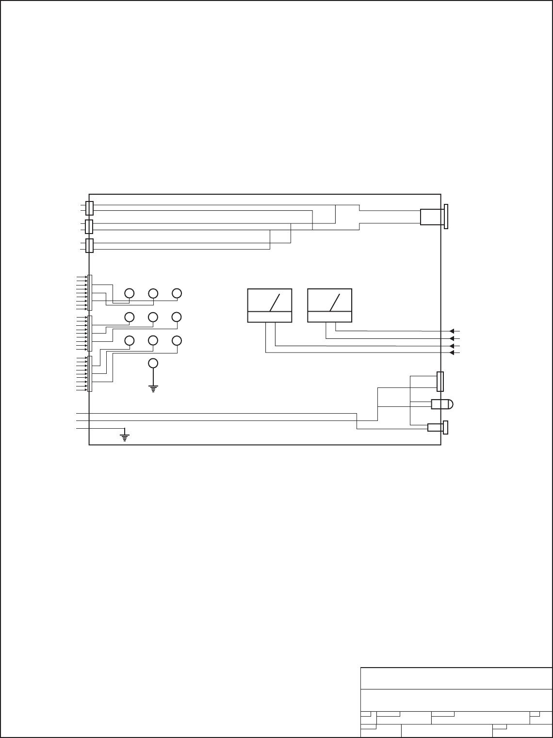
J. AUX PANEL Assy Tre
e
Item Qty Type P/N Title Detail
Top CAT AUX5K AUX PANEL 5KW USED ON 3, 4, 5 KW XMTRS
2 1 PS 484010 SW, EMERGENCY SHUTDOWN NO/NC RESETABLE
3 1 PS AC4200 AC DUPLEX OUTLET 110 VAC 15 A BLACK
4 1 PS 660110 DC PANEL METER 50 V FS HOYT MODEL 3115 1-1/2 ANA PANEL
5 1 PS 660114 DC AMP METER 500 A FS HOYT 3115 100mv FS
6 1 PS AC5101 AC PANEL MT 15 AMP 3 PIN SCW MTG
7 3 PS 453000 HW, TIP JACK RED, Insulated standard TIP JACK
8 3 PS 453001 HW TIP JACK WHITE, Insulated standard TIP JACK
9 1 PS 453002 HW, TIP JACK BLACK, Insulated standard TIP JACK
10 3 PS 453003 HW, TIP JACK BLUE, Insulated Standard TIP JACK
11 3 PS 481100 CON 9 P D-SUB MALE MALE 9P SOLDER CUP
12 3 PS 481200 CON 9P D-SUB FEMAL DB9P SOLDER CUP
13 1 PS 630002 INDICATOR LITE GREEN 120 VAC
14 1 PS MF9330A
CURRENT MONITOR, REAR
PANEL SHUNT AND FUSE MTG PLATE
15 1 PS MF9332B CHASSIS AUX5 REAR SILK AND ALODYNE
16 1 PS 480465 MOLEX PLUG HOUSING 9 POLE MATE-LOC
17 1 PS 480466 MOLEX CAP HOUSING 9 POLE
18 1 PS 480467 MOLEX STRAIN RELIEFS 9 POLE
19 3 PS 480468 MOLEX SOCKET CONTACTS CONN SOCKET 18-24 AWG TIN CRIMP
20 3 PS 480469 MOLEX PIN CONTACTS CONN PIN 18-24 AWG TIN CRIMP
21 1 PS 480470 MOLEX PLUG STR 3 PIN MOLEX 39-01-4032-P
22 1 PS 480471
MOLEX RECEPTACLE HSN 3
PIN MOLEX 39-01-4030
25 1 PS 460150 FUSE HOLDER PANEL MTG 3AG TYPE QC CON
26 1 PS 480472 MOLEX CRIMP TERM MFA1KW MOLEX MFG 39-00-0041
27 1 PS 480473
MOLEX CRIMP TERMINAL
U600LD MOLEX 39-00-0039 FEMALE
Page 32
SIZE FSCM NO.
SCALE SHEET
DWG NO. REV
Pineapple Technology, Inc.
Rocklin, CA
AUX PANEL
BLOCK DIAGRAM
P1
P2
P3
P4
P5
P6
P7
P8
P9
P1
P2
P3
P4
P5
P6
P7
P8
P9
P1
P2
P3
P4
P5
P6
P7
P8
P9
PS1
N/C PS2
1A 1B 1C
2B 2C
2A
3A 3B 3C
Ref
POWER SUPPLY
CURRENT SHARING
MONITORS
Emergency
Shutdown
N/C
ACDIS5
N/C
Power Supply
Shunt
Voltage Current
110 VAC {
110 VAC
Receptacle
Lamp
2A Fuse
SECTION VI - SCHEMATICS AND PARTS
SUB-SECTION J - UTX5K ULTRA-2
Page 33

PINEAPPLE TECHNOLOGY, INC.
UTX5K ULTRA-2 Operating and Service Manual
V
l -- SCHEMATICS AND PARTS LIS
T
K. FP6 Fuse and Shunt Panel --- Assembly Tree
Item Qty Type P/N Title Detail
Top CAT FP-6 FUSE PANEL UTX5K ULTRA INC FUSE, SHUNT, SHIELD
2 6 PS 471380 FUSE FAST ACTING 80 AMP USE WITH LFFB0001 HOLDER
3 6 PS 460190 FUSE HOLDER 400A LITTELFUSE LFFB001
5 1 PS MF9330A CURRENT MONITOR, REAR PANEL SHUNT AND FUSE MTG PLATE
6 1 PS 671000 SHUNT 1000 Amps, 100mV
7.5PS
INHOUSE_LAB
OR PTI LABOR LOADED
8.2PS
INHOUSE-ENG
TEST ENG TESTING AND FIXIT LOADED
Page 34
SIZE FSCM NO.
SCALE SHEET
DWG NO. REV
Pineapple Technology, Inc.
Rocklin, CA
FP6 Fuse and Shunt Panel
BLOCK DIAGRAM
100 mv FS
Meter
Shunt
PA2
PA2
PA4
PA4
PA6
PA6
PA5
PA5
PA3
PA3
PA1
PA1
+32VDC
GND
PS12KW
PS12KW
+32VDC
GND
GND
+32VDC
FP6 Fuse and Shunt Assy
Current Voltage
AUX Panel
125 A
Fuses
SECTION VI - SCHEMATICS AND PARTS
SUB-SECTION K - UTX5K ULTRA-2
Page 35

Section VII
Recommended
Routine
Maintenance

PINEAPPLE TECHNOLOGY, INC.
UTX5K ULTRA-2 Operating and Service Manual VII -- ROUTINE MAINTENANCE
V
II --- ROUTINE MAINTENANCE (Page 1 of 2)
The following KEY MAINTENANCE AND PERFORMANCE CHECKS should be made monthly or mor
e
frequently in some environments where dust and rodents are problems. Pineapple Technology, Inc.
recommends that the station provide a data log book to maintain these records.
DANGER: SOME OF THE RECOMMENDED TESTS REQUIRE THAT THE TRANSMITTER BE
OPERATING IN NORMAL MODE. THIS PROCEDURE MUST BE PERFORMED BY A
BROADCAST ENGINEER. MORE THAN ONE PERSON SHOULD BE PRESENT IN CASE OF A
N
ACCIDENT REQUIRING ASSISTANCE. COMMUNICATIONS TO EMERGENCY SERVICES SHOULD
BE AVAILABLE
.
TRANSMITTER
●This is an integrated 5KW transmitter and is built around six (6) PA1K amplifier assemblies
located in three (3) MFA2PA mainframes.
●Record the transmitter forward and reflected power on the watt meter provided with the transmitter.
This measured value will vary with picture content.
●Using the ADP500 and PAS6 record currents for each power LDMOS device in the transmitter.
The absolute measured value will vary with picture content so this is best performed with a fixed
signal such as SMPTE BARS, however, relative measurements are adequate to indicate a
problem at the power device stage. (See operating instructions for ADP500 and PAS6 for more
details).
●(OPTIONAL) When the transmitter is first put into service it is a good idea to go through each PA
stage and record the static bias level (NO RF DRIVE). This is done by selecting the desired
PA and using the PA INHIBIT switch. When this switch is activated, the PA drive is turned of
f
and the bias current can be measured. This is a momentary switch because when it is
activated, the PA drive is removed from all the PA's in one half of the transmitter and the outpu
t
power will be reduced by 6 db. THIS IS THE BEST METHOD TO USE WHEN
TROUBLESHOOTING A POSSIBLE BAD POWER TRANSISTO
R
.
●Record the voltage and current measurements displayed on the AUX meter.
●Carefully inspect RF Output coaxial cables for excessive heating or discoloration.
●Check DC Power connections on shunt panels and power supplies for over heating which
could indicate the hardware needs attention.
●Check DC Connections on the PA rear panel.
●Remove and clean the air filters located on the front panel of each MFA2PA mainframe assembly.
It is safe to remove the filter while the transmitter is operating. The filters may be cleaned with
a light detergent and dried completely before re-installing. Spare filters are available fro
m
Pineapple Technology, Inc. Request Part Number P/N 990199 when ordering.
Page 36

PINEAPPLE TECHNOLOGY, INC.
UTX5K ULTRA-2 Operating and Service Manual VII -- ROUTINE MAINTENANCE
V
II --- ROUTINE MAINTENANCE (Page 2 of 2)
FACILITIES
●Clean all air inlet filters and exhaust outlets to ensure that the transmitter is getting clean
unobstructed airflow.
●Perform recommended service on air condition systems.
●Rodent traps or baits should be renewed to keep the facilities clear of these pests which can
cause damage to the transmitter.
Page 37

Section VIII
Adjustments
and
Tuning

PINEAPPLE TECHNOLOGY, INC.
UTX5K ULTRA-2 Operating and Service Manual VIII -- ADJUSTMENTS AND TUNING
V
III --- ADJUSTMENTS AND TUNING (Page 1 of 2)
The UTX5K ULTRA-2 is a new series of transmitters offered by Pineapple Technology, Inc. The
latest in LDMOS device and circuit technology are employed to ensure reliable and serviceabl
e
operation for many years.
There are very few adjustments necessary to maintain full service condition. The following will
give the technician a general overview of locations for locating these adjustments:
1. MODULATOR - See details for all adjustments in the Manufacturer's Instruction Manual
provided with your transmitter. Should you have any questions, contact the Pineapple
Technology, Inc Engineering staff for assistance.
2. BPU10KW - The bandpass filter provided with your transmitter has been tuned at the factor
y
and adjustments should not be necessary and are not recommended. Any attempt to tune
or modify this filter will void manufacturer's warranty.
3. U500LD - This is the main PA board in the transmitter. Under normal operation, no adjustments
are necessary. In the unlikely event that a power transistor has to be replaced, the bias
adjustments should be reset to insure optimum operation of the transmitter. The following
procedure should be followed when making bias adjustments:
a. Remove the PA1K amplifier assembly from the transmitter and set it up on a
sturdy work bench. The bench should be equipped with a 32 VDC power supply wit
h
current capacity of 10 Amps. A VOM will be required to measure the voltage dro
p
across the precision resistors located on the monitor board.
b.
A
ttach 50 ohm load resistors to the input port and one to the output port.
If this is not done, severe damage to the PA is possible resulting in costly repair.
c. Connect the 32 VDC supply to the DC ± terminals. DO NOT TURN THE POWER SUPPLY
ON AT THIS TIME.
d. Locate the circuits where bias adjustments are necessary. Adjust only those circuits
where service was performed. Turn the bias adjustment POT's fully counter clockwise
You will find two (2) POT's for each power device with one on each gate. These ar
e
small SMT components and require gentle handling.
e. Locate the current sense resistors on the monitor board. This is a 2 watt .01 ohm
precision resistor. There is one for each device.
f. Turn the power supply on and measure the +DC to ensure that it reads +32 VDC.
g. Measure the voltage drop across the precision resistor. This should read zero (0) VDC.
Increase one of the bias POT's slowly till the meter reads 0.009 volts. Increase the
second POT until the reading is 0.018 volts. This completes the adjustment.
h. Repeat the adjustment above as necessary to set all circuit that have been serviced.
NOTICE: DO NOT USE THE BIAS CURRENT INDICATED ON THE MONITOR PANEL
OF THE ADP500 TO MAKE BIAS ADJUSTMENTS.
Page 38

PINEAPPLE TECHNOLOGY, INC.
UTX5K ULTRA-2 Operating and Service Manual VIII -- ADJUSTMENTS AND TUNING
V
III --- ADJUSTMENTS AND TUNING (Page 2 of 2)
4. PA PALLETS - These circuits are "FIXED TURNED" and do not require any field adjustment.
A
ny questions regarding pallet adjustments should be referred to the factory.
5. PHASE MATCHED CABLES - If it becomes necessary to replace one of the phase matched
cables, contact Pineapple Technology, Inc. for replacements. These cables are the ones
connected to the input and output ports on the PA1K.
6. OUTPUT POWER - The transmitter output power measurement is made using a calibrated
wattmeter provided with the transmitter. No adjustments are necessary here.
7. GAIN & PHASE MATCHING - Under normal conditions it is not necessary to make any gain
or phase adjustments in the transmitter. This transmitter is equipped with provision to adjust
phase and gain to ensure minimum power loss in the dump load and maximum forward
transfer power to the antenna. Contact Pineapple Technology, Inc. for details if this become
s
necessary.
Page 39

Section IX
Problem
Solving
&
Troubleshooting

PINEAPPLE TECHNOLOGY, INC.
UTX5K ULTRA-2 Operating and Service Manual IX -- PROBLEM SOLVING/TROUBLE SHOOTING
IX - PROBLEM SOLVING & TROUBLE SHOOTING
(
Pa
g
e 1of 3
)
The UTX5K ULTRA-2 is a "MODULAR ASSEMBLY" where most of the sub-assemblies can be
removed and or re
p
laced as necessar
y
as necessar to maintain full service. To service this transmitter,
it is best to become familiar with the various sub-assemblies b
y
reviewin
g
the transmitter block dia
g
ram
and it's associated subs shown in the introduction. An
y
work
p
erformed on a transmitter licensed b
y
the FCC must be
p
erformed b
y
q
ualified
p
ersonnel.
FAILURE ANALYSIS STARTS WITH THE FOLLOWING ASSUMPTIONS:
1. The transmitter is connected to an AC source which is within the s
p
ecified volta
g
e ran
g
e
and has am
p
le
p
ower to run the transmitter.
2. The antenna has been checked out and a
p
ro
p
er match has been verified.
3. The room tem
p
erature is < +35 de
g
rees Celsius
(
+95 de
g
rees Fahrenheit
)
4. There are no restrictions in the air flow in or out of the buildin
g
.
5. The video and aural si
g
nals to the modulator com
p
l
y
with stated s
p
ecifications.
CHECKING THE WARNING LIGHTS
There are several warnin
g
si
g
nals visible on the front of the transmitter that will alert the technician
of
p
ossible
p
roblems. When viewed from the front, all the li
g
hts should be GREEN indicatin
g
normal
o
p
eration. An alert si
g
nal is indicated b
y
a RED li
g
ht. We will focus on RED alert si
g
nals in this section
.
MFA2PA ASSEMBL
Y
FAN FAULT RED indicates that the fuse su
pp
l
y
in
g
AC to the fan has failed. The fus
e
is located
j
ust inside the front
p
anel near the to
p
.
CHECK: FUSE AND/OR FAN
DC SUPPL
Y
RED indicates a loss of +32 VDC to P
A
CHECK: DC su
pp
l
y
volta
g
e to the rear of the PA1
K
CHECK: DC su
pp
l
y
fuse located on the Fuse
p
anel located at the bottom
of the rack in the rear.
CHECK: AUX
p
anel location in the bottom half of the rack bein
g
checked
for
p
ro
p
er volta
g
e and current readin
g
s
NOTE: If all the ALERT li
g
hts are on in a
g
iven reak, this could indicate
that a breaker has tri
pp
ed
CHECK: Circuit breakers located on the front of the ACDIS5 or the
sub-
p
anel breaker located at the MAIN AC su
pp
l
y
.
Page 40

PINEAPPLE TECHNOLOGY, INC.
UTX5K ULTRA-2 Operating and Service Manual IX -- PROBLEM SOLVING/TROUBLE SHOOTING
IX - PROBLEM SOLVING & TROUBLE SHOOTING (Page 2of 3)
SHUTDOWN RED indicates that the PA has been "SHUTDOWN". There are two
possible reasons for this:
1. Heat Sink over temperature thermostat has tripped protecting the PA
CHECK: Air inlet filter for possible restrictions to air flo
w
CHECK: Fan air flow for possible fan faul
t
CHECK: Room temperature
Note: Heat sink over temperature fault is indicated by the RED alert light goin
g
ON/OFF in cycles varying in duration depending on air flow. The P
A
returns to normal operation automatically when the problem is corrected.
2. Remote Shutdown by external signals coming from other protection circuits.
CHECK: Transmitter global protection circuits.
ADP500 MONITOR
The ADP500 is a general purpose test instrument used to display PA status and measure voltage,
current and RF power levels. When combined with the PAS6 it is possible to measure the current
being drawn by each PA RF Device. In addition to its measurement features, it serves to integrat
e
fault signals for PA Assemblies, High VSWR alarms and provides an interface to the RM8 Remote
Control Unit. The ADP500 is a diagnostic tool for troubleshooting the transmitter.
With normal operating conditions, all the LED's on the front panel are GREEN. Red LED's could
indicate a fault in the transmitter that require attention.
RF PWR OFF LED is RED Will occur anytime the "SHUTDOWN LINE" (SD) is set to zero (0)
volts. The following conditions will pull the set SD to zero volts
:
1. Antenna VSWR HIGH
2. PA INHIBIT SWITCH actuated.
A
NT VSWR HIGH LED is RED This indicates that the antenna reflected power exceeded the se
t
trip point. This is an internal setting performed at the factory and is
normally set to 10% of the RF OUTPUT POWER set point.
CHECK: The transmitter output connections and antenna for
possible faults. The fault condition will automatically reset whe
n
the problem is corrected.
Page 41

PINEAPPLE TECHNOLOGY, INC.
UTX5K ULTRA-2 Operating and Service Manual IX -- PROBLEM SOLVING/TROUBLE SHOOTING
IX - PROBLEM SOLVING & TROUBLE SHOOTING (Page 3 of 3)
PA1 - PA5 LED's are RED This will indicate that the PA Pallet currents are below the 500 m
a
set point. This can occur when the PA Power device has failed.
CHECK 1: Select the PA device in question for current displa
y
on the multi-meter. Compare the reading to the station log. I
f
abnormal, it is possible that a power transistor has failed.
NOTICE: PA5 will go RED when the INHIBIT SWITCH is
actuated.
CHECK2: To confirm a failed device, it is necessary to shutdown
the transmitter and remove the PA1K power amplifier assembly
and check the device in question. Use a VOM to check the
resistance from the gate of each 1/2 of the device to ground. If
either reading is below 1K ohm it is likely that the device ha
s
failed.
POWER SUPPLY MODULE LED RED
The Power Supply Module has two warning LED's located on the front panel. Normally these LED's ar
e
GREEN indicating that the AC Line voltage and the OVER VOLTAGE circuits are operating properly
.
If either LED turns RED the module is question will be turned off and is no longer supplying powe
r
to the transmitter. These modules are "HOT PLUGGABLE" and can be removed from active service
by simply removing it from the main frame. Pineapple Technology, Inc. does not recommend an
y
attempt to service these modules. Any attempt to service may void factory warranties. Return th
e
module to Pineapple Technology, Inc. or to the manufacture for service.
NOTICE: If it becomes necessary to operate the transmitter with a missing supply module, ver
y
little if any performance degrading will be experienced. Check the AUX volt meter for any indicatio
n
of a drop in voltage (normally 32 VDC). This drop is caused by the power supply modules going int
o
"CURRENT LIMIT". It is important that the voltage be around 32 volts ±0.5. If the voltage falls belo
w
this point, it can be recovered by reducing the RF Drive level a small amount in most cases.
Page 42

Section X
Warranty

PINEAPPLE TECHNOLOGY, INC.
UTX5K ULTRA-2 Operating and Service Manual X -- WARRANT
Y
X -- WARRANT
Y
The WARRANTY provided by Pineapple Technology, Inc. (PTI) on this transmitter is detailed below.
It should be noted that some of the equipment sub-systems have warranty coverage by the orginal
manufacture that differs from the standard warranty provided by PTI Warrantydetails on equipment falling
into this category may be found in the Manufacturers instruction manual provided with the transmitter.
In all cases, replacement units of this equipment are normally in stock at PTI for quick turn service
support to our customers during the PTI Standard Warranty period.
STANDARD WARRANT
Y
Seller warrants that each Product sold by it is free of defects in materials and workmanship. Seller's
obligation under said warranty continues for a period of one (1) year from date of shippment. Repairs or
replacement of defective parts shall be the sole and exclusive remedy under waranty, at Seller option,
provided that Seller may, as an alternative, elect to refund an equitable portion of the purchase price
of the product. THIS WARRANTY IS EXPRESSLY IN LIEU OF AND EXCLUDES ALL OTHER
EXPRESS OR IMPLIED WARRANTIES, INCLUDING BUT NOT LIMITED TO WARANTIES OF
FITNESS FOR A PARTICULAR PURPOSE, USE, OR APPLICATION, AND ALL OTHER OBLIGATION
S
OR LIABILITIES ON THE PART OF THE SELLER, UNLESS SUCH OTHER WARRANTIES
OBLIGATIONS OR LIABILITIES ARE EXPRESSLY AGREED TO IN WRITING BY SELLER.
WARRANTY REPLACEMENT AND REPAIR
S
A
ll claims under warranty must be made promptly after occurrence of circumstances giving rise to thereto
and must be received within the applicable warranty period by seller or its authorized representatives.
Such claims must be documented on a PTI* Field Failure Report with a full description of the circumstances
giving rise to the claim. Before any products are returned for repair and/or adjustment, written authorization
form seller or its authorized representative for the return and instructions as to how and where these
products should be shipped must be obtained. This is to include a Return Authorization (RA) number
provided by the seller or authorized representative, this must accompany ALL returns. Any product
returned to the seller for the examination shall be sent prepaid via the means of transportation indicated as
acceptable by seller. Seller reserves the right to reject any warranty claim not promptly reported and any
claim on any item that has been altered, i.e. circuit modifications, components removed, or has been shipped
by non acceptable means of transportation. When a product has been returned for examination and inspection,
or for any other reason, customer shall be responsible for all damage resulting from improper packaging or
handling, and for loss in transit, notwithstanding any defect or nonconformity in the product. In all cases the
seller has sole responsibility for determining the cause and nature of the failure, and the Seller's
determination with regard thereto shall be final. If it is found that Seller's Product has been returned without
cause and is still serviceable, customer will be notified and the Product returned at its expense, in addition,
a charge for testing and examination may, in Sellers sole discretion be made on Products so returned.
* A field Failure Report is included at the end of this manual - Additional Field Failure Reports can be obtained by calling
Pineapple Technology, Inc. at (916) 652-1116 or you may download one from our website at www.ptibroadcast.com
in the Warranty section.
Page 43

Section XI
Extended
Warranty