Powerwave Technologies 5JS0073 Fiber-Fed Repeater/Radio Head User Manual VM10056 EN Rev P1A9 Draft
Powerwave Technologies Inc Fiber-Fed Repeater/Radio Head VM10056 EN Rev P1A9 Draft
Contents
- 1. Users Manual 1
- 2. Users Manual 2
- 3. Users Manual 3
Users Manual 2

Powerwave Fiber Optics Preface
VM100 56/EN – User’s Manual Rev. P1A9-Draft 2004-11 i
User’s Manual
Fiber Optics
–
English

Preface Fiber Optics Powerwave
ii Rev. P1A9-Draft 2004-11 VM100 56/EN – User’s Manual
This document contains descriptions of Powerwave fiber optic units. Most sections in the document do not contain comlete information for
building, installation, or commissioning systems and are therefore not allowed to be used as any kind of installation or commissioning guide.
Only sections specificly declared to be installation or commissioning instructions are allowed to be used for that purpose.
Hardware and software mentioned in this document are subjected to continuous development and improvement. Consequently, there may be
minor discrepancies between the information in the document and the performance or design of the products. Specifications, dimensions and
other statements mentioned in this document are subject to changes without prior notice.
Powerwave and its suppliers shall not be liable for any damages related to this product, or for any other damages whatsoever caused of the use of or inability to use any Powerwave
product. This is applicable even if Powerwave has been advised of the damage risk. Under any circumstances, Powerwave's entire liability shall be limited to replace such defective
software or hardware which was originally purchased from Powerwave.
LinDAS is a trademark of Powerwave. Microsoft is a registered trademark of Microsoft Corporation. Windows, Windows 98, Windows NT and Windows 2000 are trademarks of
Microsoft Corporation. Intel and Pentium are registered trademarks of Intel Corporation. Hayes is a registered trademark of Hayes Microcomputer Products, Inc. Other trademarks
mentioned in this manual are trademarks or registered trademarks of their respective owners.
Powerwave Technologies, Inc., 1801 East St. Andrew Place, Santa Ana, CA 92705 USA
Phone: +1 714 466 1000 – Fax: +1 714 466 5800 – Internet: www.powerwave.com
This manual or parts of it may not be reproduced without the written permission of Powerwave Technologies.
Infringements will be prosecuted. All rights reserved.
Copyright © Powerwave Technologies, Inc., CA 92705 USA, 1994 – 2004.

Powerwave Fiber Optics Preface
VM100 56/EN – User’s Manual Rev. P1A9-Draft 2004-11 iii
Contents
Abbreviations .................................................................................................................................. v
1. Safety ......................................................................................................................................... 1-1
Human Exposure of RF Radiation ..................................................................................... 1-3
Repeater Antennas ........................................................................................................ 1-3
Installation and Maintenance of Antenna Systems ....................................................... 1-3
Radiation Exposure ....................................................................................................... 1-4
Radiation Safety Distances ........................................................................................... 1-4
Static Electricity ................................................................................................................. 1-6
2. Introduction ............................................................................................................................... 2-1
Fiber Optics in General ...................................................................................................... 2-2
Fiber Optic Transmission Versus Electrical Transmission ........................................... 2-3
Duplex Transmission .................................................................................................... 2-4
System Building Blocks ..................................................................................................... 2-5
FON, Fiber Optic Node ................................................................................................. 2-6
FOU, Fiber Optic Unit .................................................................................................. 2-6
BMU, Base Station Master Unit ................................................................................... 2-7
RMU, Repeater Master Unit ......................................................................................... 2-7
FOR, Fiber Optic Repeater ........................................................................................... 2-7
OCM, Optical Converter Module ................................................................................. 2-8
RH, Remote Hub ........................................................................................................... 2-9
3. FON, Fiber Optic Node ............................................................................................................. 3-1
Functional Description ....................................................................................................... 3-1
Block Diagram .............................................................................................................. 3-2
R2R Communication .................................................................................................... 3-4
Gateway Node ............................................................................................................... 3-5
Alarm ............................................................................................................................ 3-5
Power ............................................................................................................................ 3-5
Backup Power ............................................................................................................... 3-5
Design ................................................................................................................................ 3-6
The FON Board ............................................................................................................. 3-6
Indicators ....................................................................................................................... 3-6
RF and Optical Ports ..................................................................................................... 3-8
Connection Ports ........................................................................................................... 3-9
Operational Control ............................................................................................................ 3-11
4. RF Over Fiber ........................................................................................................................... 4-1
The RF Modulated Signal Paths ........................................................................................ 4-2
Downlink RF Signal Path ............................................................................................. 4-3
Uplink RF Signal Path .................................................................................................. 4-8
FOU, Fiber Optic Unit .................................................................................................. 4-10
Noise, Intermodulation and Dynamic Signal Range ..................................................... 4-11
Simplex Transmission ........................................................................................................ 4-12
Duplex Transmission ......................................................................................................... 4-13

Preface Fiber Optics Powerwave
iv Rev. P1A9-Draft 2004-11 VM100 56/EN – User’s Manual
5. IP Over Fiber ............................................................................................................................ 5-1
IP Network Terminology ................................................................................................... 5-2
Requirements ..................................................................................................................... 5-3
F-Net Characteristics ......................................................................................................... 5-4
Node Units ......................................................................................................................... 5-5
The FON Unit Net Interfaces ....................................................................................... 5-6
Network Example .............................................................................................................. 5-7
6. Commissioning ......................................................................................................................... 6-1
Equipment Required .......................................................................................................... 6-1
Commissioning the Fiber Optic System ............................................................................ 6-2
Master Unit Downlink Path .......................................................................................... 6-2
Slave Units ................................................................................................................... 6-3
System Configuration Examples ....................................................................................... 6-6
7. Passive Devices ........................................................................................................................ 7-1
OSP, Optical Splitter ......................................................................................................... 7-2
Graphic Symbol ............................................................................................................ 7-3
Examples ...................................................................................................................... 7-3
WDM, Wavelength Division Multiplexer ......................................................................... 7-4
Graphic Symbol ............................................................................................................ 7-5
Example ........................................................................................................................ 7-5
Fiber Optic Cables ............................................................................................................. 7-6
Powerwave Patch Cables .............................................................................................. 7-8
Fiber Optic Connectors ...................................................................................................... 7-9
Connector Types ........................................................................................................... 7-10
Handling Connectors .................................................................................................... 7-11
8. Troubleshooting ........................................................................................................................ 8-1
Index ............................................................................................................................................... I-1
Questionnaire .............................................................................................................................. Q-1

Powerwave Fiber Optics Preface
VM100 56/EN – User’s Manual Rev. P1A9-Draft 2004-11 v
Abbreviations
Abbreviations used in the document, in the software and in supported hardware:
3G Third Generation mobile system.
AGC Automatic Gain Control.
ALI Alarm Interface (board).
ALR Powerwave low power repeater (usually called Compact repeater).
ALT Powerwave low power train repeater.
AMPS Advanced Mobile Phone Service.
AR Powerwave repeater (usually called standard repeater).
BCCH Broadcast Control Channel.
BMU Base station Master Unit.
BA Booster Amplifier.
BS Base Station.
BSA Band Selective Amplifier (board).
BSC Band Selective Compact repeater (board).
BSel Band Selective repeater.
BTS Base station Transceiver System.
CDMA Code Division Multiple Access.
CH Central Hub.
CHA Channel Amplifier (board).
CMB Combiner
CSA CDMA/WCDMA Segment Amplifier (board).
CSel Channel Selective repeater.
CU Control Unit (board).
CW Continuous Wave.
DAMPS Digital Advanced Mobile Phone Service.
DAS Distributed Antenna System.
DC Directional Coupler.
DCS Digital Communication System (same as PCN).
DFB Distributed Feedback.
DIA Distribution (board).
DIF Diplex Filter.
DL Downlink (signal direction from base station, via repeater, to mobile station).
DNS Domain Name Server.
DMB Digital Multimedia Broadcasting.
DPX Duplex filter.
EEPROM Electrical Erasable Programmable Read Only Memory.
EGSM Extended Global System for Mobile communication.
ETACS Extended Total Access Communication System.
ETS European Telecommunications Standards.
F2F Fiber to Fiber link (renamed to F-link/FLI).
FCC Federal Communications Commission.
FLI Fiber Link Interface.
F-link Fiber link.
F-net Fiber network.
FON Fiber Optic Node.
FOR Fiber Optic Repeater.
FOT Fiber Optic Transceiver.
FOU Fiber Optic Unit.
GSM Global System for Mobile communication.
GPS Global Position System.
HW Hardware
ICMP Internet Control Message Protocol.
IM Intermodulation.
IP Internet Protocol.
LAN Local Area Network.
LED Light Emitting Diode.

Preface Fiber Optics Powerwave
vi Rev. P1A9-Draft 2004-11 VM100 56/EN – User’s Manual
LinDAS Light Indoor Distributed Antenna System.
LNA Low Noise Amplifier (unit).
MACID Physical address to RIA or CU board (comparable with Ethernet card MACID).
MRX Measurement Receiver (board).
MS Mobile Station.
MSC Mobile Switching Center.
NAPT Network Address and Port Translation.
NMT Nordic Mobile Telephone (system).
NS Name Server.
OCM Optical Converter Module.
OM-Online Operation and Maintenance Online.
OMS Operation and Maintenance System.
OMT16 Operation and Maintenance Terminal (replaced with OMT32).
OMT32 Operation and Maintenance Terminal (replaced with OM-Online).
OSP Optical Splitter.
PA Power Amplifier (board).
PEP Peak Envelope Power.
PCN Personal Communication Network (same as DCS).
PCS Personal Communication System.
PPP Point to Point Protocol.
PSM Power Supply Module.
PSTN Public Switched Telephone Network.
PSU Power Supply Unit.
PTFE Polytetrafluoro Ethylene (Teflon).
R2R Repeater to Repeater (Powerwave specific network).
R2R net R2R network.
RAS Remote Access Service.
RCC Remote Communication Control (unit).
RCM RF Combiner Module.
RCU Remote Control Unit.
RF Radio Frequency.
RH Remote Hub.
RIA Repeater Interface Adapter (board).
RMS Root Mean Square.
RMU Repeater Master Unit.
RSSI Received Signal Strength Indication.
RTC Real Time Clock.
RX Receiver
SLW Sliding Window (Powerwave specific protocol).
SW Software
TACS Total Access Communication System.
TDMA Time Division Multiple Access.
TX Transmitter
UDP User Datagram Protocol.
UL Uplink (signal direction from mobile station via repeater to base station).
UPS Uninterruptible Power Supply.
VAC Voltage Alternating Current.
VDC Voltage Direct Current.
WAN Wide Area Network.
WBA Wideband Amplifier (board).
WCDMA Wideband Code Division Multiple Access.
WCS Wideband Coverage System.
WDM Wavelength Division Multiplexer.
WLI Wire Link Interface.
W-link Wire link.
W-net Wire network.
WRH Wideband Radio Head.
Powerwave Fiber Optics
VM100 56/EN – User’s Manual Rev. P1A9-Draft 2004-11 1 - 1
1. Safety
In this chapter, the word ’repeater’ includes all Powerwave repeating units, such as
repeaters, hubs and radio heads.
It is necessary that any personnel involved in installation, operation or service of units
included in an Powerwave repeater system understand and follow the below points.
•The Powerwave repeaters are designed to receive and amplify signals from one or
more base stations and retransmit the signals to one or more mobile stations. And, also
to act the other way round, that is to receive signals from one or more mobile stations,
amplify and retransmit the signals to the base stations. Powerwave repeater systems
must be used exclusively for this purpose and nothing else.
•Units supplied from the mains must be connected to grounded outlets and in
conformity with the local prescriptions.
•Power supply units supplied from the mains contain dangerous voltage that can cause
electric shock. Disconnect the mains prior to any work in such a unit. Local
regulations are to be followed when servicing such units.
Authorized service personnel only are allowed to service units while the mains is
connected.
•All RF transmitting units, including repeaters, will generate radio signals and thereby
give rise to electromagnetic fields that may be hazardous to the health of any person
who is extensively exposed close to an antenna.
See the Human Exposure of RF Radiation section on page 1-3.
Beryllium oxide
•Beryllium oxide (BeO) may be contained in power devices, for instance in dummy
loads in directional couplers (DCC), in combiner units (CMB), and in attenuators on
the FON board. Beryllium oxide is poisonous if present as dust or smoke that can be
inhaled.
Do not file, grind, machine, or treat these parts with acid.
Hydrogen fluoride
•Coaxial cables used in many Powerwave systems have the insulation made of PTFE,
polytetrafluoro ethylene, that gives off small amounts of hydrogen fluoride when
heated. Hydrogen fluoride is poisonous. Do not use heating tools when stripping off
coaxial cable insulation.
No particular measures are to be taken in case of fire because the emitted
concentration of hydrogen fluoride is very low.
•A lithium battery is permanently mounted in repeater CU units, and in FON and OCM
units. Due to the risk of explosion, this battery must only be removed from the board
by an Powerwave authorized service technician.
•NiCd batteries are mounted on the FON unit. These batteries contain environmental
poisonous substances. If replaced, the old batteries should be taken care of as stated
in the local prescriptions.

Fiber Optics Powerwave
1 - 2 Rev. P1A9-Draft 2004-11 VM100 56/EN – User’s Manual
•The FON unit contains a class IIIb laser transmitter that emits 2 – 5mW invisible laser
radiation during operation. Avoid direct exposure from unconnected laser transmitter
or fiber cord as follows:
– Do not power up the FON unit if a fiber cable is not attached to the fiber output
UL port, neither if a fiber cable is attached to the port but unattached in the other
end.
– Never look in the end of a fiber cable. The 1310nm and 1550nm laser light is
not visible, so no signal identification can be made anyway. Use always an
instrument, such as a power meter to detect signaling.
– Never use any kind of magnifying devices that can focus the laser light to an
unprotected eye.

Powerwave Fiber Optics
VM100 56/EN – User’s Manual Rev. P1A9-Draft 2004-11 1 - 3
Human Exposure of RF Radiation
This section contains a few words about repeater antennas and prescriptions for
installaton and maintenance of antenna systems. Also, it describes how to calculate
safety distances needed for RF radiation at different antenna power and frequencies.
Repeater Antennas
To be able to receive and transmit signals as described in the first bulleted paragraph on
page 1-1, a repeater is connected to a donor antenna directed towards the base station,
and a service antenna directed towards the coverage area. A fiber optic cable from the
base station might, however, be substituted for the donor antenna.
Installation and Maintenance of Antenna Systems
Installation and maintenance of all repeater antenna systems must be performed with
respect to the radiation exposure limits for public areas.
The antenna radiation level is affected by the repeater output power, the antenna gain,
and by transmission devices such as cables, connectors, splitters and feeders.
Have also in mind that the system minimum coupling loss, typical between 25dB and
35dB, is determined by a standard with the purpose to protect base stations from noise
and other performance dropping effects.

Fiber Optics Powerwave
1 - 4 Rev. P1A9-Draft 2004-11 VM100 56/EN – User’s Manual
Radiation Exposure
WHO, World Health Organization, and ICNIRP, International Commission on Non-
Ionising Radiation Protection, have determined recommendations for radiation
exposure.
ICNIRP recommends not to exceed the following radiation power for public exposure:
Frequency Radiation power
900MHz 4,5W/m²
1800MHz 9,0W/m²
2100MHz 10,0W/m²
For antennas larger than 20cm the maximum radiation power can be calculated by using
the following formula:
where
S = Radiation power in W/m².
P = Output power in W.
r = Distance between antenna and human in meter.
To tackle the worst case successfully, the calculation does not consider system power
reducing actions, such as power control and DTX.
Figure 1-1 shows the safety distance to an antenna due to the RF radiation. The distance
is depending on the antenna output power and frequency, which is illustrated with two
graphs in the figure.
One of the graphs applies to 4.5W/m2 (900MHz) and the other to 9.0W/m2 (1800MHz)
or 10.0W/m2 (2100MHz).
The safety distance range in Figure 1-1 is 0 to 1.4 meter that covers an antenna power
range of 10dBm to 50dBm (0.01W to 100W).
Radiation Safety Distances
This section illustrates the safety distances to the antennas for some typical repeater
configurations.
Outdoor GSM 900MHz
The safety distance can be read to 0.75 meter in Figure 1-1 as the maximum radiation
power is 4.5W/m² for 900MHz.
SP
4Sr2
uu
-------------------
=
Repeater output power +33dBm
Feeder loss –5dB
Antenna gain +17dBi
EIRP +45dBm

Powerwave Fiber Optics
VM100 56/EN – User’s Manual Rev. P1A9-Draft 2004-11 1 - 5
Figure 1-1. Safety distance to active antenna
Indoor GSM 900MHz
The safety distance can be read to 0.035 meter for 4.5W/m² (900MHz).
Outdoor UMTS Standard High Power
The safety distance can be read to 0.9 meter for 10W/m² (2100MHz).
Indoor UMTS
The safety distance can be read to 0.035 meter for 10W/m² (2100MHz).
10
15
20
25
30
35
40
0 0.1 0.2 0.3 0.4 0.5 0.6 0.7 0.8 0.9 1.0
45
50
1.1 1.2 1.3 1.4
0.01
0.03
0.1
0.3
1.0
3.2
10.0
31.6
100
4.5W/m2 (900MHz)
9W/m2 (1800MHz)
10W/m2 (2100MHz)
Safety distance to antenna in meter
Antenna output power in dBm
Antenna output power in W
Repeater output power +22dBm
Feeder loss –5dB
Antenna gain +1dBi
EIRP +18dBm
Repeater output power +38dBm
Feeder loss –5dB
Antenna gain +17dBi
EIRP +50dBm
Repeater output power +24dBm
Feeder loss –5dB
Antenna gain +3dBi
EIRP +22dBm

Fiber Optics Powerwave
1 - 6 Rev. P1A9-Draft 2004-11 VM100 56/EN – User’s Manual
Static Electricity
Static electricity means no risk of personal injury but it can severely damage essential
parts of the equipment, if not handled carefully.
Parts on the printed circuit boards as well as other parts in the equipment are sensitive
to electrostatic discharge.
Never touch the printed circuit boards or uninsulated conductor surfaces unless
absolutely necessary.
If you must handle the printed circuit boards or uninsulated conductor surfaces, use ESD
protective equipment, or first touch the chassis with your hand and then do not move
your feet on the floor.
Never let your clothes touch printed circuit boards or uninsulated conductor surfaces.
Always store printed circuit boards in ESD-safe bags.

Powerwave Fiber Optics
VM100 56/EN – User’s Manual Rev. P1A9-Draft 2004-11 2 - 1
2. Introduction
The first official demonstration of the fiber optics technology took place at the British
Royal Society in London, 1870. It was given by natural philosopher John Tyndall. He
used a container with a spout and water. As the water poured through the spout, the light
from the inside of the container followed the curved water path.
Figure 2-1. John Tyndall’s first guided light transmission
This demonstation was the first research into guided light transmission.
Ten years later, in 1880, William Wheeling patented a method to transfer light in tubes,
’piping light’ through plumbing. However, this never took off because Edison invented
the light bulb.
Alexander Graham Bell was, about the same time, the first ever to arrange an optical
amplitude modulated transmission over 200m. This was, however, achieved by emitting
light beams in free space. Graham Bell’s idea was not to use wire for telephone
communication.
In the decade around 1950, the first practical all-glass fibers was developed which gave
a success to the technology. It was Brian O’Brien at the American Optical Company and
Narinder Kapany at the Imperial College of Science and Technology in London who
was first to practically use an image-transmitting fiber-scope. Narinder Kapany was the
man who coined the term ’fiber optics’ in 1956.
Since that time, the laser and then the semiconductor laser have been very important
inventions making the technology to grow increasingly and also become a fascinating
and mysterious industry, where much of the technology has been isolated from
outsiders.
This manual is an attempt to open the curtain for a small area of this technology – fiber
optic transmission between repeaters.
Fiber Optics Powerwave
2 - 2 Rev. P1A9-Draft 2004-11 VM100 56/EN – User’s Manual
Fiber Optics in General
In the beginning, when fiber optics became in practical use, a ’first window’ with a
wavelength of 850nm was used. It had a loss of approximately 3dB/km.
As the technology developed, the ’second window’ at 1300nm became more attractive
because of the lower loss, below 1dB/km.
Today, the ’third window’ at 1550nm is the most attractive wavelength with a loss of
0.2dB/km for silica-based fibers.
The ’second window’ at 1300nm can today, with silica-based fibers, achieve a loss of
only 0.35dB/km.
The following figure illustrates the three ’windows’ where the loss is low over the usable
wavelength range.
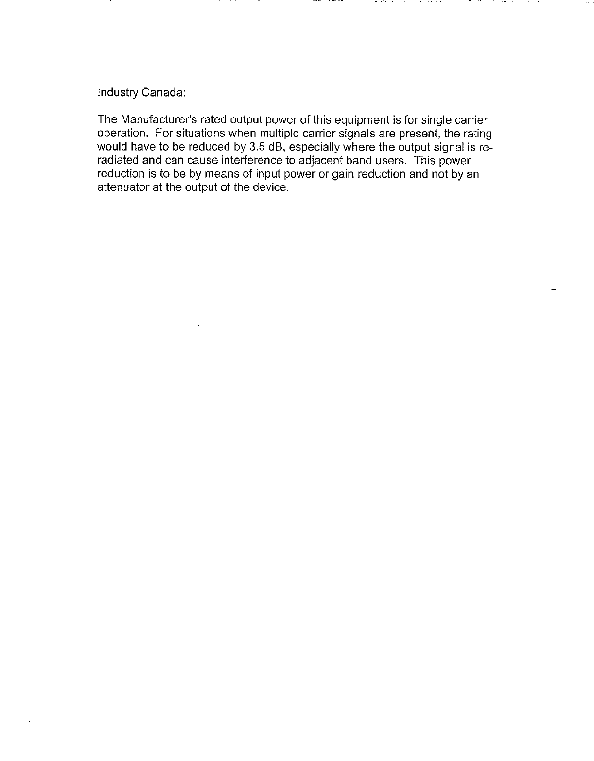
Figure 2-2. The three wavelength windows
Figure 2-2 illustrates the losses for the three wavelengt windows, with silica-based
fibers.
The large absorption peaks in the diagram are caused mainly by moisture in the fiber,
and by scattering at shorter wavlengths.
Figure 2-2 also shows the visible light wavelegth band, the loss curve caused by
Rayleigh scattering at shorter wavelengths, and the loss curve caused by fiber molecule
absorption at longer wavelengths.
The wavelengts used by the FON boards in the repeaters are within the second window
(1310nm) and the third window (1550nm).
0
10
01600
5
600 800 1000 1200 1400
dB/km
1800 2000nm
Third
window
Second
window
First
window
Rayleigh
scattering
loss
Fiber
molecule
absorption
loss
Visible light

Powerwave Fiber Optics
VM100 56/EN – User’s Manual Rev. P1A9-Draft 2004-11 2 - 3
Fiber Optic Transmission Versus Electrical Transmission
This section points out some differences between fiber optic transmission and electrical
transmission via copper. The most signficant differences are loss, bandwidth,
electromagnetic interference, security, signal quality, and weight.
Low loss per km
In general, optical transmission over fiber offers the lowest propagation loss but also
more complexity. It also adds conversion loss for electrical-to-optical signal conversion,
and conversion loss the other way round.
This means that there is a break-even distance due to the propagation loss, where fiber
optics starts to be more cost-effective.
For repeater usage, the following suggestion can be applicable:
For a distance shorter than 100m, use coaxial cable.
For a distance between 100m and 1000m, let the situation determine.
For a distance longer than 1000m, use fiber optics.
High bandwidth
High bandwidth is an advantage for fiber optics. It has a higher bandwidth than any other
alternative (the immense potential bandwidth of 1tHz, that is 1012Hz).
High bandwidth makes fiber optics become more and more common even on short
distances as the Internet and other types of data communication demand high
bandwidths. This makes fiber optic parts more and more common, which in the long run
decreases the break-even distance for fiber optics usage.
No electromagnetic (EM) interference
As fiber consists of a non-conductive material, it is unaffected by all EM radiation.
Security
For the same reason that fiber is immune to EM radiation, it does not emit any EM
radiation that can be detected.
High signal quality
Because of the immunity to EM radiation, high bandwidth, and low loss, the signal
quality can be considerably better for fiber optic transmission than for electric
transmission in copper.
Low weight
A copper cable usually has a weight of ten times that of a fiber cable.

Fiber Optics Powerwave
2 - 4 Rev. P1A9-Draft 2004-11 VM100 56/EN – User’s Manual
Duplex Transmission
Full duplex transmission can be performed in a single fiber by transmitting one
wavelength in one direction and another wavelength in the reverse direction. A
wavelength division multiplexer (WDM) in each end separates the signals to an optical
transmitter and an optical receiver.
This is further described in Chapter 7,Passive Devices.

Powerwave Fiber Optics
VM100 56/EN – User’s Manual Rev. P1A9-Draft 2004-11 2 - 5
System Building Blocks
This section contains short descriptions of the Powerwave fiber optic building blocks
listed below.
Building modules
•FON, Fiber Optic Node, page 2-6.
•FOU, Fiber Optic Unit, page 2-6.
Repeater units
•BMU, Base Station Master Unit, page 2-7.
•RMU, Repeater Master Unit, page 2-7.
•FOR, Fiber Optic Repeater, page 2-7.
•OCM, Optical Converter Module, page 2-8.
•RH, Remote Hub, page 2-9.
Fiber Optics Powerwave
2 - 6 Rev. P1A9-Draft 2004-11 VM100 56/EN – User’s Manual
FON, Fiber Optic Node
The FON unit is the heart of all Powerwave fiber optic repeater systems. The FON unit
contains an optical transmitter and an optical receiver. No other Powerwave repeater
building block has these facilities.
Figure 2-3. The FON unit
This unit is normally part of the FOU, Fiber Optic Unit.
The FON unit is detailed in Chapter 3,FON, Fiber Optic Node.
FOU, Fiber Optic Unit
The FOU, Fiber Optic Unit, is a complete unit for fiber optic interconnection of two or
more repeaters. It is built up on a flanged plate and can be inserted in all types of LGP
Allgon AR repeaters. In the simpliest configuration, it contains a FON board and a DPX
filter.
Figure 2-4. The FOU unit
Figure 2-4 shows an example of the FOU with a typical configuration. Both RF and
optical devices, such as DPX filters, RF combiners, optical splitters and WDMs, can be
configured on the FOU plate. The FON board is always included in the FOU.
The FOU is also described in the FOU, Fiber Optic Unit section in Chapter 4.
P102
P130
Beryllium
oxide
hazard
P103
P101
P114
P108P116P111
P105P109P115
P106
P104
RX
TX
P113
P112
P110
P102
P130
Berylliu m
oxide
hazard
P103
P101
P114
P108P116P111
P105P109P115
P106
P104
RX
TX
P113
P112
P110
Powerwave Fiber Optics
VM100 56/EN – User’s Manual Rev. P1A9-Draft 2004-11 2 - 7
BMU, Base Station Master Unit
A BMU is an RF repeater type equipped with a FOU that gives the repeater ability to
transmit and receive optical signals on the service side.
The BMU has an RF port for BTS connection and up to four fiber optic ports that can
be connected to FORs.
By configuring the FOU with WDMs and OSPs, up to approximately four FORs can be
fed in parallel by a BMU via double or single fiber communication. Up to approximately
eight FORs can be fed with a high cover and two FOUs.
The BMU is described, with all included sub units, block diagram, and mechanical
design, in the VD203 66/EN, AR Repeaters, User’s Manual.
RMU, Repeater Master Unit
An RMU is an RF repeater type equipped with an FOU that gives the repeater ability to
transmit and receive optical signals on the service side.
The RMU has an RF port for a donor antenna and up to four fiber optic ports that can be
connected to FORs.
By configuring the FOU with WDMs and OSPs, up to four FORs can be fed in parallel
by a BMU via double or single fiber communication. Up to eight FORs can be fed with
a high cover and two FOUs.
The RMU is described, with all included sub units, block diagram, and mechanical
design, in the VD203 66/EN, AR Repeaters, User’s Manual.
FOR, Fiber Optic Repeater
A FOR is an RF repeater type equipped with an FOU that gives the repeater ability to
transmit and receive optical signals on the donor side.
The FOR has a fiber optic donor port and an RF port for a service antenna.
By configuring the FOU with a splitter, another FOR can be optically connected to the
same RF system.
The FOR can be connected to a BMU or RMU.
The FOR is described, with all included sub units, block diagram, and mechanical
design, in the VD203 66/EN, AR Repeaters, User’s Manual.
ALLGON
RF
ALLGON
RF
RF
ALLGON
Fiber Optics Powerwave
2 - 8 Rev. P1A9-Draft 2004-11 VM100 56/EN – User’s Manual
OCM, Optical Converter Module
The OCM is, principally, an indoor rack mounted BMU with several channels for
different bands, systems, and operators.
The front view of the OCM is shown in Figure 2-5.
Figure 2-5. OCM, Optical Converter Module
The OCM can contain up to three FON boards, and a large number of splitter
configurations.
The OCM is designed to work with an RCM, RF Combiner Module, in a DAS concept,
see Figure 2-6.
Figure 2-6. The concept of DAS
System, installation, and commissioning descriptions of the OCM are found in the
VD205 03/EN, LinDAS, Installation Guide.
A
B
C
A1
A5
A2
A6
A3
A7
A4
A8
B1
B5
B2
B6
B3
B7
B4
B8
C1
C5
C2
C6
C3
C7
C4
C8
A1
A2
B1
B2
C1
C2
RF IN/OUT ANT STATUS LOCAL O&M OPTICAL IN/OUT
OPTICAL CONVERTER MODULE
MAINS
REMOTE WLI WLI
CAUTION !
MAX RF INPUT +36dBm
0
I
RF IN/OUT BTS RF IN/OUT
RF COMBINER MODULE
A1
A5
A2
A6
A3
A7
A4
A8
B1
B5
B2
B6
B3
B7
B4
B8
C1
C5
C2
C6
C3
C7
C4
C8
A
B
C
A1
A5
A2
A6
A3
A7
A4
A8
B1
B5
B2
B6
B3
B7
B4
B8
C1
C5
C2
C6
C3
C7
C4
C8
RF IN/OUT ANT STATUS LOCAL O&M OPTICAL IN/OUT
OPTICAL CONVERTER MODULE
MAINS
REMOTE WLI WLI
CAUTION !
MAX RF INPUT +36dBm
A1
A2
B1
B2
C1
C2
A1
A2
B1
B2
C1
C2
CAUTION !
MAX BTS RF INPUT +40dBm
RCM
OCM
CH
RH
BTS
RH
Powerwave Fiber Optics
VM100 56/EN – User’s Manual Rev. P1A9-Draft 2004-11 2 - 9
RH, Remote Hub
The RH is, principially, a FOR unit in a compact cabinet. The RH unit has, however, no
FOU but the FON board is mounted directly in the cabinet.
The RH is used in DAS systems. The front view of the RH is shown in Figure 2-7.
Figure 2-7. RH, Remote Hub
Figure 2-8 shows a Remote Hub cabinet inside with fiber optic cables from the OCM.
Figure 2-8. Remote hub donor fiber connection
Installation and commissioning descriptions of the RH are found in the VD205 03/EN,
LinDAS, Installation Guide.
P102
P130
Beryllium
oxide
hazard
P103
P101
P114
P108
P112
P111
P105
P110
P109
P115
P106
P104
RX
TX
P113
ANT
LO HI
PSM
FON
Fiber optic cables
from OCM.

Fiber Optics Powerwave
2 - 10 Rev. P1A9-Draft 2004-11 VM100 56/EN – User’s Manual

Powerwave Fiber Optics
VM100 56/EN – User’s Manual Rev. P1A9-Draft 2004-11 3 - 1
3. FON, Fiber Optic Node
This chapter describes the functionality, the design, and the operational control of the
FON unit.
Figure 3-1. The FON unit
A description of RF transmission over fiber using the FON unit is found in Chapter 4,
RF Over Fiber. A description of IP network using the FON unit is found in Chapter 5,
IP Over Fiber.
Functional Description
The Fiber Optic Node, FON, is a bi-directional electrical/optical signal converter and a
node in either a wire network or a fiber network. It has also functionality for:
– Electrical and optical signal supervision.
– Internal and external alarm handling.
– RS232 interface for local PC control via an O&M software (OM-Online).
– Remote control via an O&M software (OM-Online or OMS).
– Interface for RCC.
– Interface for WLI, wire network.
– Interface for FLI, fiber optic network.
– Battery backup with charger.
The FON unit can be installed in all Powerwave repeaters, remote hubs, and radio heads.
This section contains a description of the FON unit, including block diagram, RF paths,
IP path, R2R communication, FON as gateway node, alarm handling, power, and
backup power.
P102
P130
Beryllium
oxide
hazard
P103
P101
P114
P108P116P111
P105P109P115
P106
P104
RX
TX
P113
P112
P110
Fiber Optics Powerwave
3 - 2 Rev. P1A9-Draft 2004-11 VM100 56/EN – User’s Manual
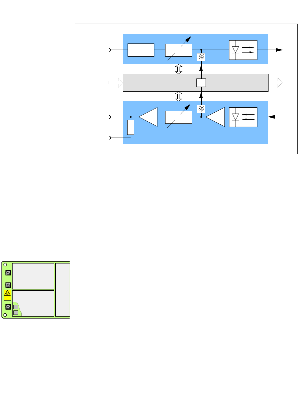
Block Diagram
Figure 3-2. FON block diagram
Figure 3-2 shows a block diagram of the FON unit. The downlink and uplink RF signal
paths are described below.
The control unit block contains circuitry and software for control of the RF paths, local
and remote communication with O&M software, protocols for IP and R2R networks,
internal and external alarm handling, power supervision, etc.
The control unit has a number of input and output ports not shown in the block diagram.
These ports are described in the Connection Ports section on page 3-9.
RF Path 1
The RF IN port (P101) is usually connected to BTS/DL in a BMU (Base station Master
Unit), or to the UL amplifier in a FOR (Fiber Optic Repeater). The input frequency is
800 – 2200MHz and the input power 10 – 36dBm.
The first attenuator is a 16dB, 8W power device that is a security attenuator for the FON
unit. It consists of two attenuators located under the shield, see the figure. There is a
FON type without these input attenuators intended for specific configurations (described
in the Uplink RF Signal Path section in Chapter 4).
After the attenuator there is a software adjustable 0 – 20dB attenuator, manually set by
the operator via O&M software. This attenuator is correctly set when the input power to
the optical transmitter is 0dBm (examples are found in Chapter 6,Commissioning).
The optical transmitter converts the electrical RF modulated signal to a 1310 or 1550nm
optical RF modulated signal and injects it into a fiber for transmission to one or more
fiber optic receivers. The output signal power is 2 – 5dBm, or 0.5 – 2dBm at low power
(NF: 30 – 35dB and IP3: 30 – 35dBm).
The IP3 is: 68dBm for channel selective repeater with 2 channels.
65dBm for channel selective repeater with 4 channels.
54dBm for band selective repeater.
16dB, 8W FO
RF IN TXP101
FO
RF OUT RXP102
Control Unit
P103
TEST
–15dB
0 – 20dB
0 – 20dB
IP
16dB16dB
RF Path 1
RF Path 2
P102
Bery llium
oxide
hazard
P103
P101

Powerwave Fiber Optics
VM100 56/EN – User’s Manual Rev. P1A9-Draft 2004-11 3 - 3
RF Path 2
An optical 1310 or 1550nm input signal is received by an optical receiver. The power
range for this input is between –15dBm and 1dBm optical power. To avoid receiver
saturation, it should be less than 1dBm.
After converting the optical RF modulated signal to an electrical RF modulated signal,
it is amplified in two 16dB amplifier stages with a noise figure of 4dB each.
Between the two 16dB amplifiers there is a software adjustable 0 – 20dB attenuator,
manually set by the operator via O&M software. This attenuator is differently set
depending on the FON usage.
•If the FON unit is part of a BMU, then it is adjusted to an uplink gain that is dependent
on the ratio of the BTS and the repeater coverage areas.
•If the FON unit is part of a FOR, then it should be adjusted to match the repeater input
amplifier power range.
Examples of this are found in Chapter 6,Commissioning.
The RF OUT port (P102) is usually connected to BTS/UL in a BMU, or to the DL
amplifier in a FOR. The output power can be between 0dBm and 20dBm with a
minimum noise (above the thermal noise) of 22dB.
There is also an RF test output (P103) with an output level of 15dB below the RF OUT
level. This output is intended for signal measurement without disconnecting the RF
cable.
IP Path
The IP communication circuitry is located in the control unit.
The subcarrier from the control unit is fed, via a filter, to the RF path before the optical
transmitter, see Figure 3-2. In the connection point, the subcarrier is added to the RF
signal. In the following optical transmitter, the RF signal with the added subcarrier is
converted to an optical signal and transmitted to the connected optical receiver or
receivers.
A received optical RF signal with an added subcarrier is converted to an electrical signal
in the optical receiver. After the first amplifier, the subcarrier passes a filter and is then
fed to the IP circuitry input in the control unit.
The subcarrier signal takes no power from the optical RF transmission.
Fiber Optics Powerwave
3 - 4 Rev. P1A9-Draft 2004-11 VM100 56/EN – User’s Manual
R2R Communication
This section describes how to use the FON unit in R2R networks. The R2R network
itself, its configuration, and R2R statistics are further described in the VM100 01/EN,
OM-Online, User’s Manual.
The R2R (Repeater to Repeater) network is an old Powerwave specific WLI network
with SLW protocol and wire interconnection (W-net).
WLI stands for Wire Link Interface, W-net for Wire network.
SLW (Sliding Window) is an Powerwave specific protocol developed for the R2R
network.
The IP network can be used in fiber networks as well as in wire networks. However, the
IP wire network and the R2R wire network have different protocols and can, for this
reason, not communicate with each other.
R2R network characteristics
The R2R uses a twisted pair or RS-485 bi-directional bus with a master unit and slave
units. The bus is connected to the FON boards via the WLI ports, see the Connection
Ports section on page 3-10.
An example of an R2R network with four FON nodes is shown in Figure 3-3.
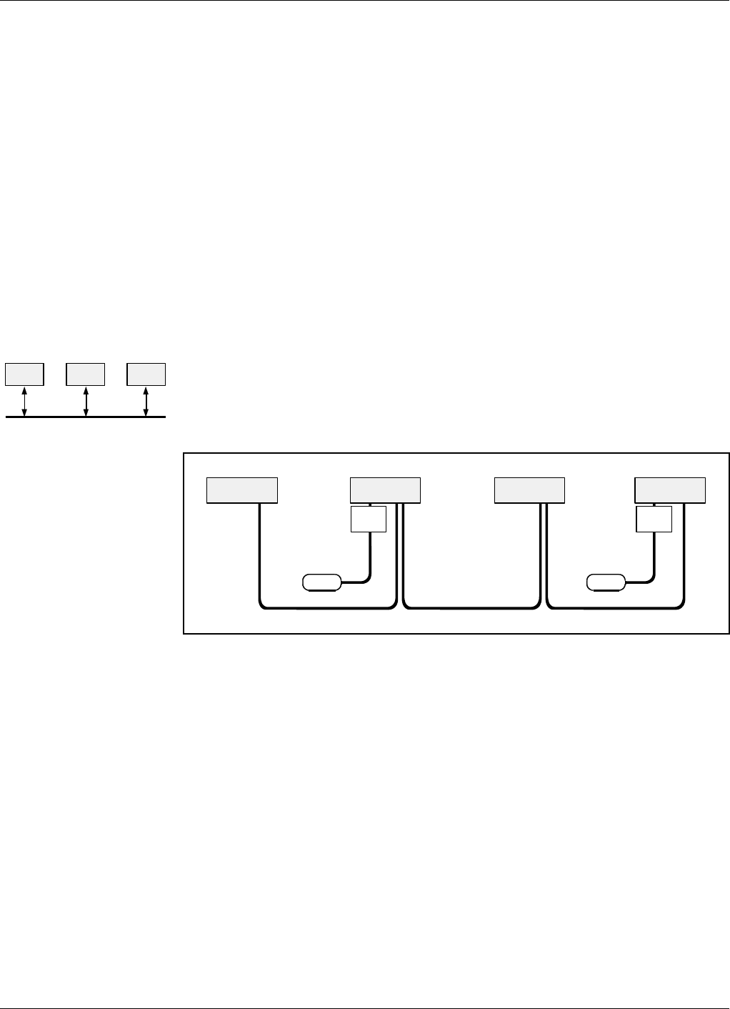
Figure 3-3. R2R network with four FON nodes
Gateway The R2R network can contain maximum 12 nodes. One or several of these nodes can be
gateway nodes, that is to be able to communicate remotely with an O&M software via
modem. A description of the FON unit as gateway is found in the Gateway Node section
on page 3-5.
The R2R network in Figure 3-3 contains two gateway nodes (connected to the PSTN).
Control station All nodes in an R2R network can, and should, be configured with Control Station
Capability enabled, which means that they can be the master unit if the current master
unit ceases to work.
FON FON FON
PSTNPSTN
FON FON FON FON
RCC RCC

Powerwave Fiber Optics
VM100 56/EN – User’s Manual Rev. P1A9-Draft 2004-11 3 - 5
Gateway Node
A FON unit can be used as a network gateway node for IP networks as well as for R2R
networks by being connected to an RCC (Remote Communication Control) unit, see
Figure 3-3.
The RCC unit is connected to the FON board via the RCC port, see the Connection Ports
section on page 3-10.
Both the FON unit and the RCC unit can be installed in all Powerwave repeaters and
remote hubs.
The gateway node in various repeater types is further detailed in the VM100 01/EN,
OM-Online, User’s Manual.
Alarm
The FON unit has the same alarm and event handling as the Powerwave repeaters and
remote hubs. Consequently, the entire Alarms and Events chapter in the VM100 01/EN,
OM-Online, User’s Manual is applicable also for the FON unit.
This includes also the four external alarms that are connected to the FON board via the
Alarm port, see the Connection Ports section on page 3-9.
Power
The FON unit requires 6.0 –8.0V power supply. All Powerwave repeaters and remote
hubs have a 7V DC power supply that is used for this purpose. This power is connected
to the FON board via the Power port, see the Connection Ports section on page 3-9.
Backup Power
If a power failure occurs, a backup battery has capacity to supply the FON control unit
with the network for up to30 minutes at room temperature. This time is intended for
alarm transmission.
Fiber Optics Powerwave
3 - 6 Rev. P1A9-Draft 2004-11 VM100 56/EN – User’s Manual
Design
This section describes the FON board layout, including indicators, coaxial ports, optical
ports, connectors, and jumpers.
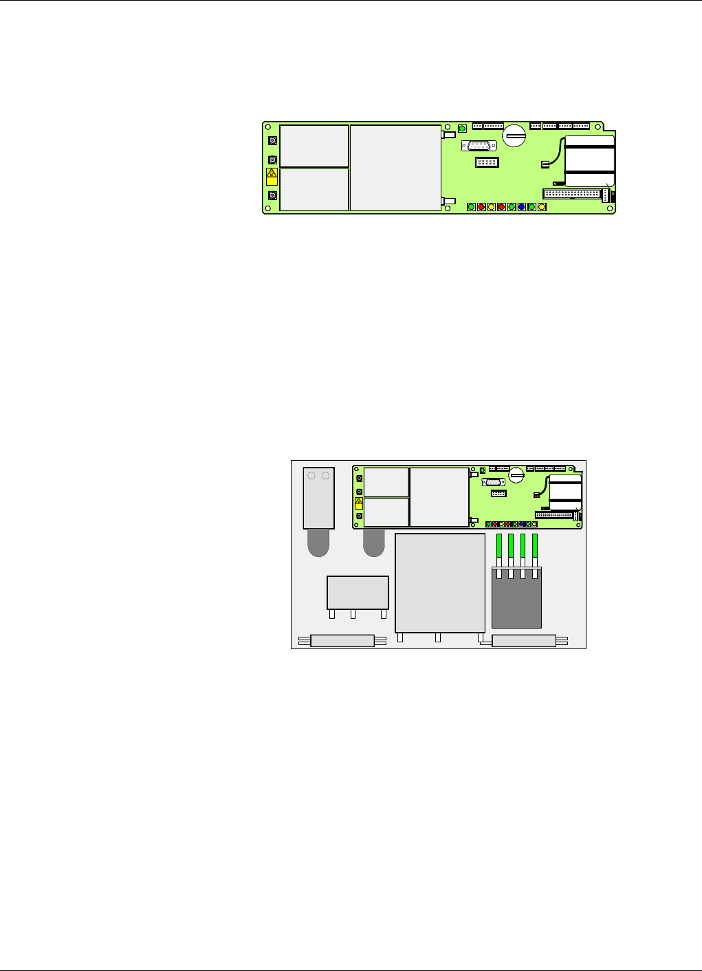
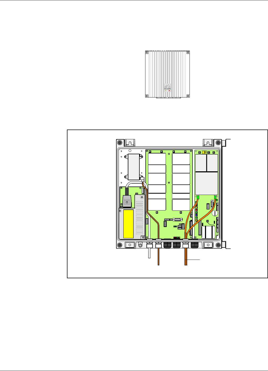
The FON Board
The FON board is built up on a printed circuit board that also contains the battery
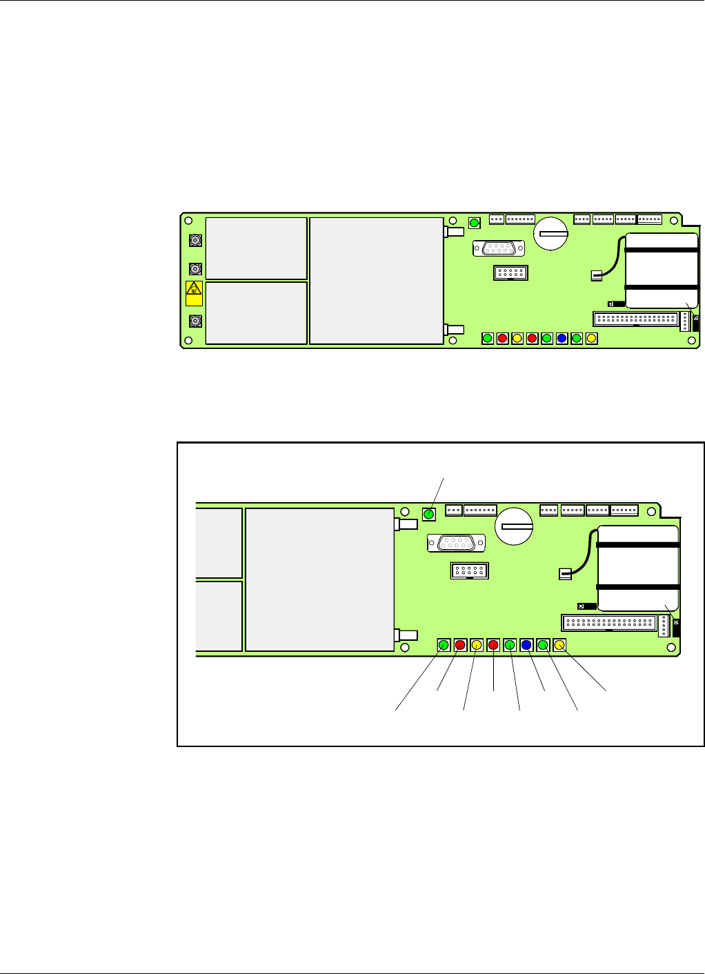
backup. The FON board is shown in Figure 3-4.
Figure 3-4. The FON board
Indicators
Figure 3-5. FON indicators and ports
The FON board contains the below described LED indicators.
FLI (or F2F) fiber network
Green LED that indicates, with a flashing light, that the unit receives data over the sub
carrier. A steady light indicates that the unit does not currently receive any data, or there
is no other node in the network.
P102
P130
Bery llium
oxide
hazard
P103
P101
P114
P108P116P111
P105P109P115
P106
P104
RX
TX
P113
P112
P110
OPER
FAULT
POWER
BOOT
P130
P114
P108P116P111
P105P109P115
P106
P104
RX
TX
P113
P112
P110
WLI/R2R
DATA
BATT
CHARGE
FLI

Powerwave Fiber Optics
VM100 56/EN – User’s Manual Rev. P1A9-Draft 2004-11 3 - 7
OPER
Green LED that lights up approximately 15 seconds after the mains is switched on. It
shows, with a steady light, that the unit is ready for operation.
FAULT
Red LED that flashes 15 – 20 seconds after the mains is switched on. Then, it flashes for
less serious alarms (Error) and is lit with a steady light for fatal alarms (Critical).
POWER
Yellow LED that indicates present power. It is lit with a steady light after the mains is
switched on.
BOOT
Red LED that is lit with a steady light when the control unit boots, that is for 10 –
15 seconds after the mains is switched on. Then, it flashes for the next 5 – 10 seconds.
After that, if no error is detected, the LED is off.
If an error occur, then the LED is lit.
WLI (or R2R) wire network
Green LED that indicates, with a flashing light, that the unit is receiving data over the
sub carrier. A steady light indicates one of the following three states: The unit is
currently not receiving any data. The unit is currently not a Control station. Or, there is
no other node in the network.
DATA
Blue LED that indicates data transmission in the W-net.
BATT
Green LED that indicates, with a steady light, that the battery pack currently is used as
power source.
CHARGE
Yellow LED that indicates battery charge with a steady light.
Fiber Optics Powerwave
3 - 8 Rev. P1A9-Draft 2004-11 VM100 56/EN – User’s Manual
RF and Optical Ports
Figure 3-6. RF and optical ports
The FON board has three coaxial ports and two optical ports for the downlink and uplink
RF signal. The following table shows the port numbers, connector types, and the port
usages.
Caution
Beryllium oxide
There are two power attenuators at the P101 port (under the shield) on the FON board,
see Figure 3-6. These may contain beryllium oxide (BeO), which is poisonous. See
Chapter 1,Safety.
P102
Beryllium
oxide
hazard
P103
P101
RX
TX
Port Type Description
P101 SMA Electrical RF input port (to the optical TX port).
P102 SMA Electrical RF output port (from the optical RX port).
P103 SMA Electrical RF output port (15dB below the P102 port).
RX DIN/APC Optical input port (to the P102 and P103 RF ports).
TX DIN/APC Optical output port (from the P101 RF port).
Powerwave Fiber Optics
VM100 56/EN – User’s Manual Rev. P1A9-Draft 2004-11 3 - 9
Connection Ports
Except for the downlink and uplink RF ports, the FON board contains the below
described connection ports.
P104 – Debug
This port is used only for development and debugging.
P105 – Front LED indicators
P105 is a 4 pole male connector used for the yellow and red LED indicators located on
the front cabinet door.
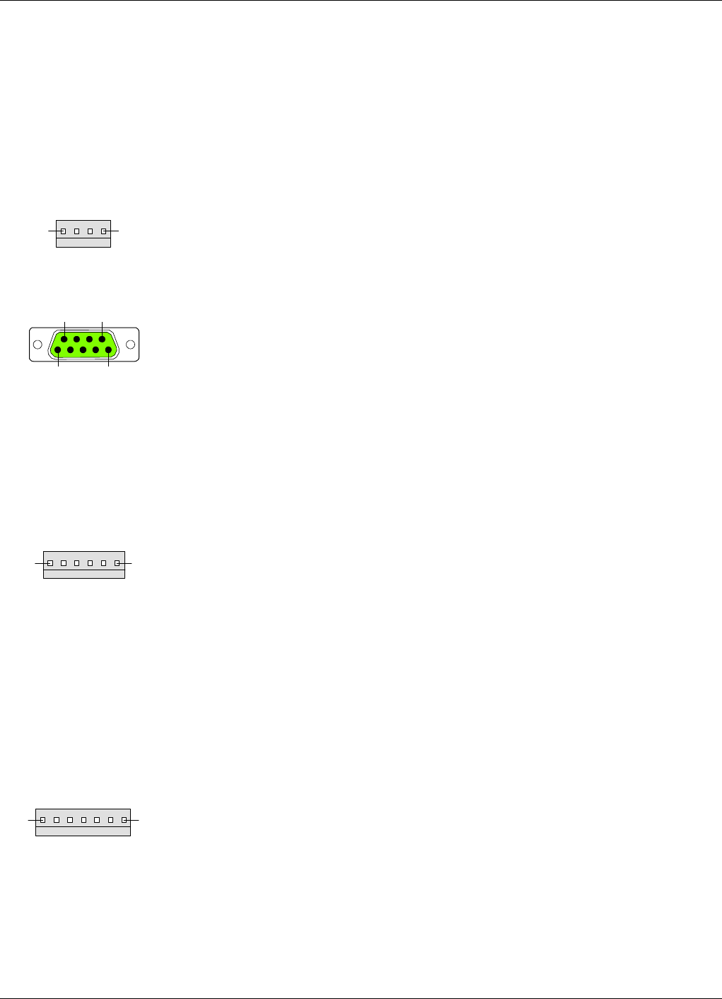
P106 – PC
P106 is a 9 pole D-sub female RS-232 port used for local PC communication.
This port has the following pinning:
Pin 1 Not used (GND).
Pin 2 Data from FON to PC.
Pin 3 Data from PC to FON.
Pin 4 DTR from PC to FON.
Pin 5 GND
Pin 6 DSR from FON to PC.
Pin 7 RTS from PC to FON.
Pin 8 CTS from FON to PC.
P108 and P116 – Power
Power and alarm ports for the FON board.
P108 and P116 are 6 pole male connectors used for providing the FON board with
power. P108 and P116 are connected in parallel for cascade connection or single use.
These ports have the following pinning:
Pin 1 +7V in.
Pin 2 +7V backup out (controlled by P114).
Pin 3 Alarm output.
Pin 4 GND
Pin 5 Not used.
Pin 6 GND.
P109 – Alarm
P109 is a 7 pole male alarm connector used for external alarm sensors.
This port has the following pinning:
Pin 1 AIC Ground.
Pin 2 AIC Ground.
Pin 3 AI1 External alarm input 1 – EAL1.
Pin 4 AI2 External alarm input 2 – EAL2.
Pin 5 AI3 External alarm input 3 – EAL3.
Pin 6 AI4 External alarm input 4 – EAL4.
Pin 7 Not used.
14
51
6 9
16
17
Fiber Optics Powerwave
3 - 10 Rev. P1A9-Draft 2004-11 VM100 56/EN – User’s Manual
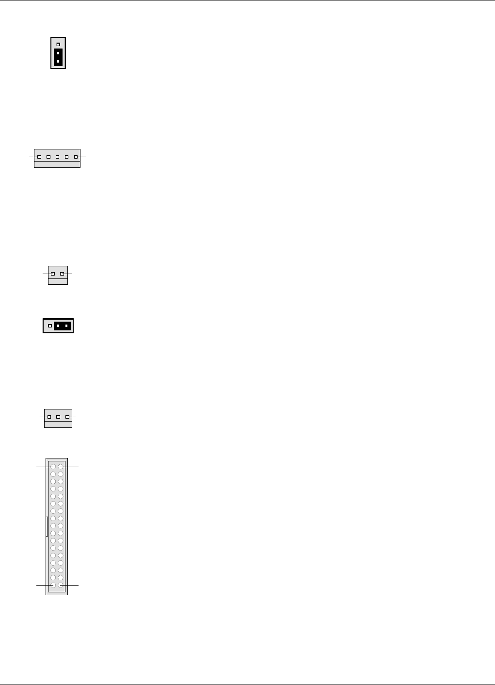
P110 – W-link jumper
This jumper is used to terminate units in a W-link. It has to be set in the parking state for
all units except for the first and last units in a W-link.
Parking state is shown in the figure (the pins farest away from the battery pack
interconnected).
The opposite state terminates the W-link.
P111, P112 – WLI ports
P111 and P112 are 5 pole male connectors used for interconnecting nodes in WLI-nets
(IP or R2R networks).
P111 and P112 are identical and connected in parallel. One of the connectors are
intended to be used from the previous node, and the other connector to the next node in
the network. Either of P111 or P112 can be used for the first and the last unit in the net
chain.
P113 – Batteries
P113 is a 2 pole male connector used for the on-board backup batteries.
P114 – Backup power output
This jumper sets the backup power output state. The OFF state is shown in the figure
(the pins closest to the battery pack interconnected).
This jumper has to be in the OFF state when used in an OCM unit. Otherwise, it shall be
in the ON state (opposite to the figure).
P115 – Future port
P115 is a 3 pole male connector intended for future use (not used for the time being).
P130 – RCC port
P130 is a 34 pole 2 line male connector used for connecting an RCC, Remote
Communication Control unit.
The P130 connector contains both the modem connection and RCC power supply.
15
12
13
12
33 34

Powerwave Fiber Optics
VM100 56/EN – User’s Manual Rev. P1A9-Draft 2004-11 3 - 11
Operational Control
The FON unit can be locally or remotely controlled via an O&M software (remote
control via modem).
All descriptions in this document refer to the OM-Online O&M software. Parameter
names may differ somewhat when working with OMS, but the functionality of the
parameters are the same.

Fiber Optics Powerwave
3 - 12 Rev. P1A9-Draft 2004-11 VM100 56/EN – User’s Manual

Powerwave Fiber Optics
VM100 56/EN – User’s Manual Rev. P1A9-Draft 2004-11 4 - 1
4. RF Over Fiber
This chapter describes the downlink RF modulated signal from the BTS to the repeater
antenna, and the other way around from the repeater antenna to the BTS. The description
is focused on the optical part of the RF transmission.
The chapter is divided into the following main parts:
•RF signal path overview for downlink and uplink signals, page 4-2.
•Detailed description of the downlink signal path, page 4-3.
•Detailed description of the uplink signal path, page 4-8.
•Brief description of the FOU, Fiber Optic Unit, page 4-10.
•Brief descriptions of noise, intermodulation, and dynamic signal range, page 4-11.
•Some examples of simplex transmission, page 4-12.
•Some examples of full-duplex transmission, page 4-13.
Fiber Optics Powerwave
4 - 2 Rev. P1A9-Draft 2004-11 VM100 56/EN – User’s Manual
The RF Modulated Signal Paths
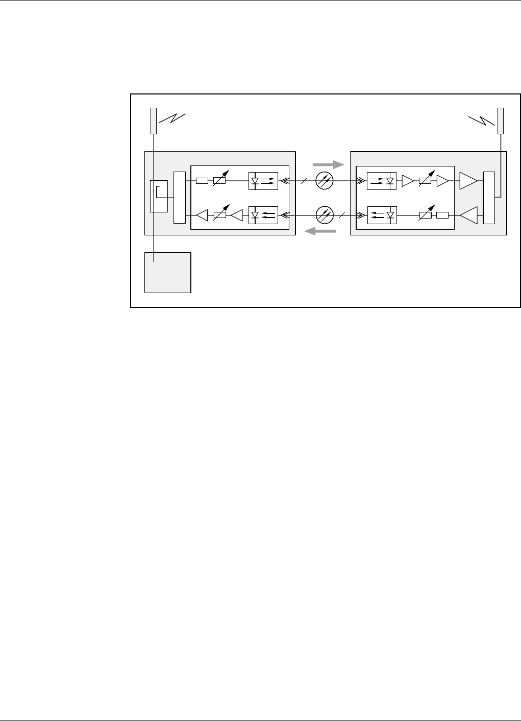
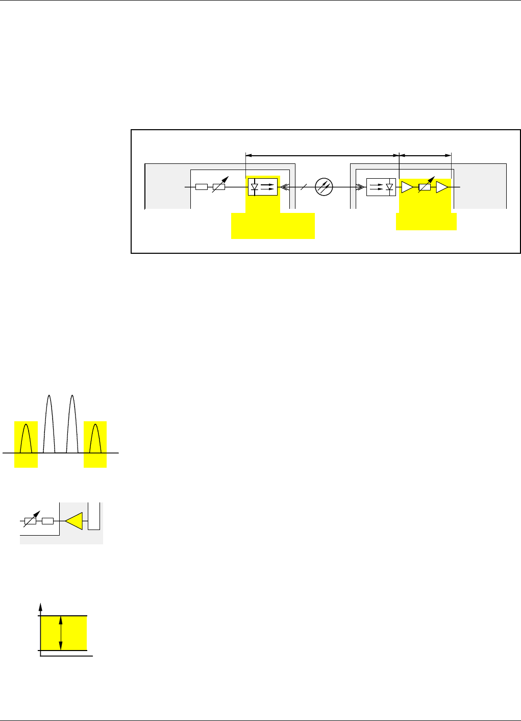
Figure 4-1 illustrates the downlink RF modulated signal path from the BTS via a BMU,
optical fiber, and a FOR to the repeater antenna. And also the uplink path from the
repeater antenna back to the BTS.
Figure 4-1. Downlink and uplink RF modulated signal paths
As the signal paths mainly are handled by the FON units, the signal description for this
unit, found in the RF Path 1 and RF Path 2 sections in Chapter 3, is applicable to the
downlink and uplink RF modulated signal paths. The amplifiers and duplex filter (DPX)
in the FOR are, however, not included in the FON description, but are found in the
repeater manual (VD203 66/EN, AR Repeaters, User’s Manual).
The signal paths are, however, also described below, but more in terms of radio
frequency signals in the entire chain, from the BTS to the repeater antenna, and the other
way around.
BTS
FON
BMU
FON
FOR
DPX
DC 1TX
RX
1
TX RX
DPX
UL
DL
Powerwave Fiber Optics
VM100 56/EN – User’s Manual Rev. P1A9-Draft 2004-11 4 - 3
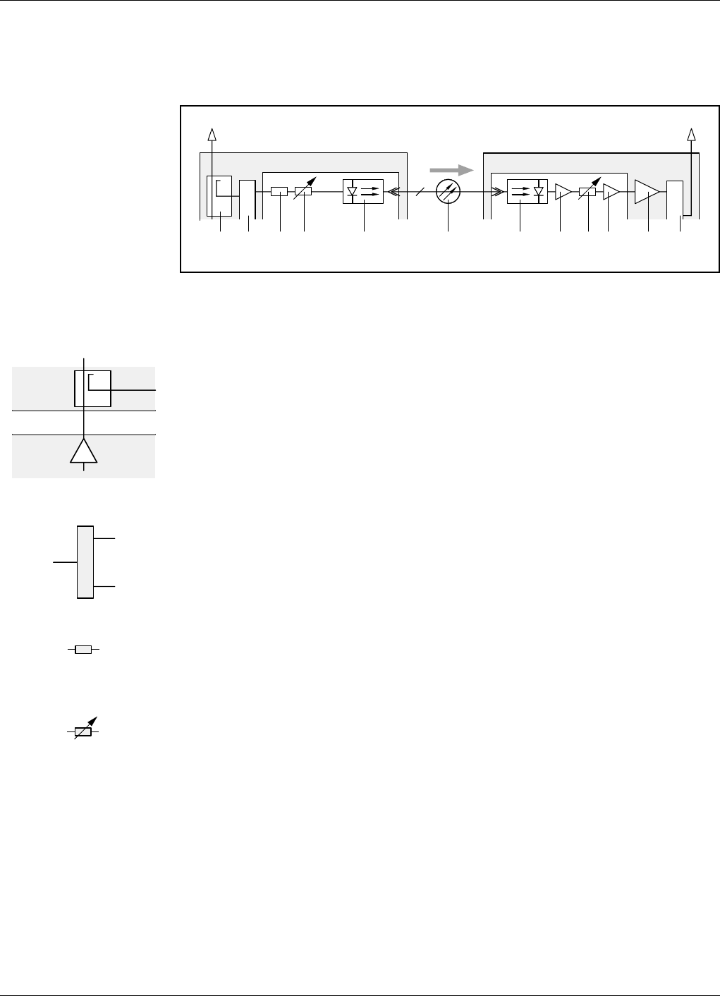
Downlink RF Signal Path
The downlink RF modulated signal path, from the BTS to the repeater antenna, is shown
in Figure 4-2. The item numbers in the figure are described below.
Figure 4-2. Downlink RF transmission path
1. DC coupler
The DC coupler on the BTS antenna path picks up the BTS downlink signal with a fixed
coupling loss of 20dB.
The left figure shows the DC coupler connected to the BTS antenna path and the BTS
downlink amplifier with a typical noise figure of 5dB.
The values in the figure are typical values that can vary from one system to another.
2. DPX duplex filter
A Powerwave duplex filter separates the downlink and uplink signal frequencies
between the BTS antenna path and the separate input/output RF ports of the FON unit.
The Powerwave DPX filter has a typical loss of 1dB.
3. Power attenuator
An input 16dB/8W power attenuator is a security attenuator for the FON unit.
4. Software adjustable attenuator
The software adjustable 0 – 20dB attenuator is set manually via an O&M software. This
is described in the FON section of the VM100 01/EN, OM-Online, User’s Manual.
The attenuator should be set to a calculated value that attenuates the signal power to
0dBm to the following optical transmitter.
Example: Presume the typical values in the figures above are used, that is:
– BTS output = 40dBm
– DC coupler loss = 20dB
– DPX filter loss = 1dB
– power attenuator = 16dB
Set the attenuator to 3dB (40dBm – 20dB – 1dB – 16dB = 3dB).
BMU FOR
DC
1
TX RX
2 3 4 5 6 7 8 9 10 11 12
1
FON
FON
DL
DPX
DPX
NF 5dB
40dBm
20dB
BTS
BMU
DL
DC
DPX
16dB, 8W
0 – 20dB
Fiber Optics Powerwave
4 - 4 Rev. P1A9-Draft 2004-11 VM100 56/EN – User’s Manual
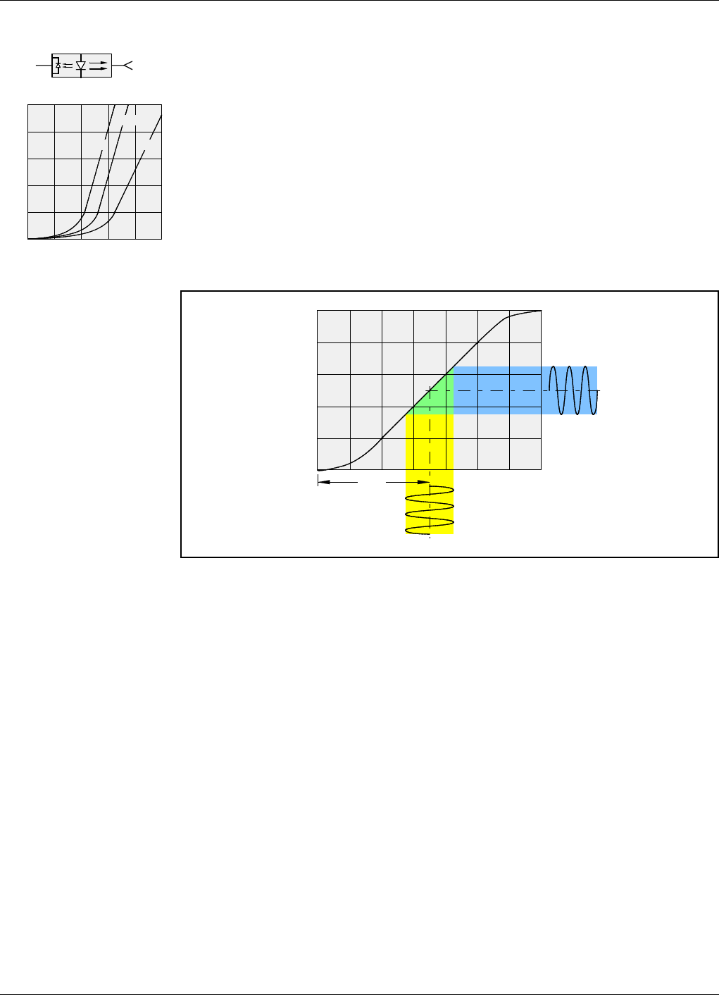
5. Optical transmitter
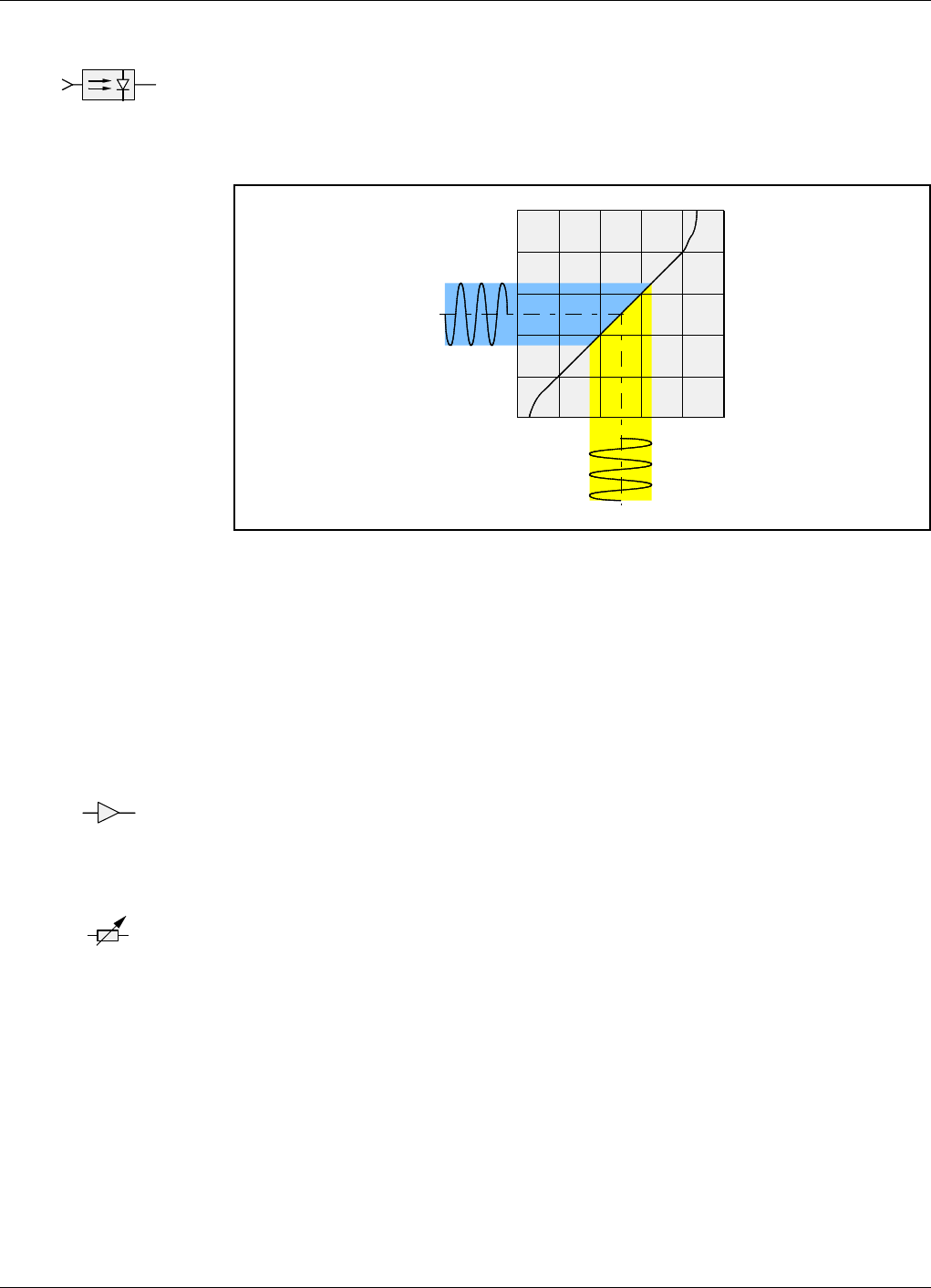
The optical transmitter converts the electrical RF modulated signal to a 1310 or 1550nm
optical RF modulated signal. The transmitter ends with an optical female connector.
The transmitter has a laser diode for transmitting the optical signal, and a back-facet
monitor photodiode that provides a real-time monitoring of the optical output.
The back-facet monitor photodiode is used to control the laser treshold current that is
temperature dependent. See the treshold current bends of the optical power output
curves for some different temperatures in the left figure. The values shown in the
diagram are typical values that can vary for diffierent devices.
By using the back-facet monitor photodiode, the optical transmitter is compensated for
different operating temperatures and a temperature non-dependent electrical-to-optical
curve can be used, see Figure 4-3.
Figure 4-3. Electircal to optical signal conversion
The RF modulated optical output signal PO-RF has the same shape as the RF modulated
electrical input signal IRF, see Figure 4-3. The IBIAS current is set to keep the dynamic
'IRF current range within the straight part of the curve, provided the input power is kept
on about 0dBm (or lower). If the input power is much higher, then the PO-RF will be
distored.
The output signal can be the default power range or be set to a low power range via an
O&M software. Default power range means 3.5 – 5dBm, low power range 0.5 – 2dBm.
The noise figure for the optical transmitter is 30 – 35dB.
The IP3 level is 30 – 35dBm.
TX
0
2
4
6
8
10
0 20406080100
P
o
(mW)
IF (mA)
0°C
25°C
50°C
PO
I
IRF
PO-RF
IBIAS

Powerwave Fiber Optics
VM100 56/EN – User’s Manual Rev. P1A9-Draft 2004-11 4 - 5
6. Optical transmission
In the example shown in Figure 4-2, the optical downlink transmission (between the
optical transmitter and the optical receiver) is built-up with two optical connectors and
one single-mode fiber.
The optical connectors are of DIN/APC type. The coupling loss (gap and misalignment
losses) for this connector type is approximately 0.5dB.
The single-mode fiber loss is approximately 0.35dB/km for 1310nm and 0.20dB/km for
1550nm.
The maximum fiber attenuation should not exceed 15dB.
Example:
At a distance of three kilometers, the optical transmission loss for a 1310nm signal is
approximately 2dB (0.5dB + 3x0.35dB + 0.5dB), and for a 1550nm signal
approximately 1.6dB (0.5dB + 3x0.20dB + 0.5dB).
The optical transmission loss will increase for devices used to split the signal path to
more than one receiver or to use the same fiber for both transmission directions. This is
further described in the Simplex Transmission section on page 4-12, and in the Duplex
Transmission section on page 4-13.
Note that all optical losses, except for FOT/FOT and FON/FON conversion losses, are
to be multiplied by two when converting to electrical RF losses.
The reason why the optical loss has to be multiplied by two (in dB) is that the light
detector in the optical receiver has a square shaped input area and thus extracts the
square root of the input power.
1
Fiber Optics Powerwave
4 - 6 Rev. P1A9-Draft 2004-11 VM100 56/EN – User’s Manual
7. Optical receiver
The optical receiver performs the opposite function to the optical transmitter. It contains
a light detector, that is a semiconductor photodiode that produces current in response to
incident 1310 or 1550nm light.
The conversion from an optical signal to an electrical RF signal is shown in Figure 4-4.
Figure 4-4. Optical receiver light detector
The optical input power to the light detector has to be between –15dBm and 1dBm. To
avoid detector saturation that will result in signal distortion, it should be less than 1dBm.
The optical output power is independent of the TX attenuation.
The light detector adds very low amounts of shot noise and thermal noise.
8. Amplifier
The converted electrical RF modulated signal is amplified in a 16dB amplifier with a
noise figure of 4dB.
9. Software adjustable attenuator
The software adjustable 0 – 20dB attenuator is set manually via an O&M software. This
is described in the FON section of the VM100 01/EN, OM-Online, User’s Manual.
Setting, see the following amplifier.
RX
PO
I
IRF
PO-RF
16dB
0 – 20dB

Powerwave Fiber Optics
VM100 56/EN – User’s Manual Rev. P1A9-Draft 2004-11 4 - 7
10. Amplifier
The RF modulated signal is finally amplified in the last FON stage, a 16dB amplifier
with a noise figure of 4dB.
The output signal minimum noise (above the thermal noise) is 22dB.
The output power is set with the previous adjustable attenuator to match the repeater
amplifier input level (maximum 13dBm).
To achieve maximum output power from the repeater, the input signal level to the
repeater has to be correct with respect to the gain. The signal level is adjusted with the
FON adjustable attenuator.
11. Repeater amplifier
The repeater amplifier consists of a low noise amplifier, LNA, a repeater amplifer stage,
and a power amplifier. These stages are described in the VD203 66/EN, AR Repeaters,
User’s Manual.
12. DPX duplex filter
Separates the downlink and uplink signal frequencies between the repeater service
antenna and the separate downlink/uplink FOR amplifiers. The DPX filter is described
in the VD203 66/EN, AR Repeaters, User’s Manual.
16dB
DPX
Fiber Optics Powerwave
4 - 8 Rev. P1A9-Draft 2004-11 VM100 56/EN – User’s Manual
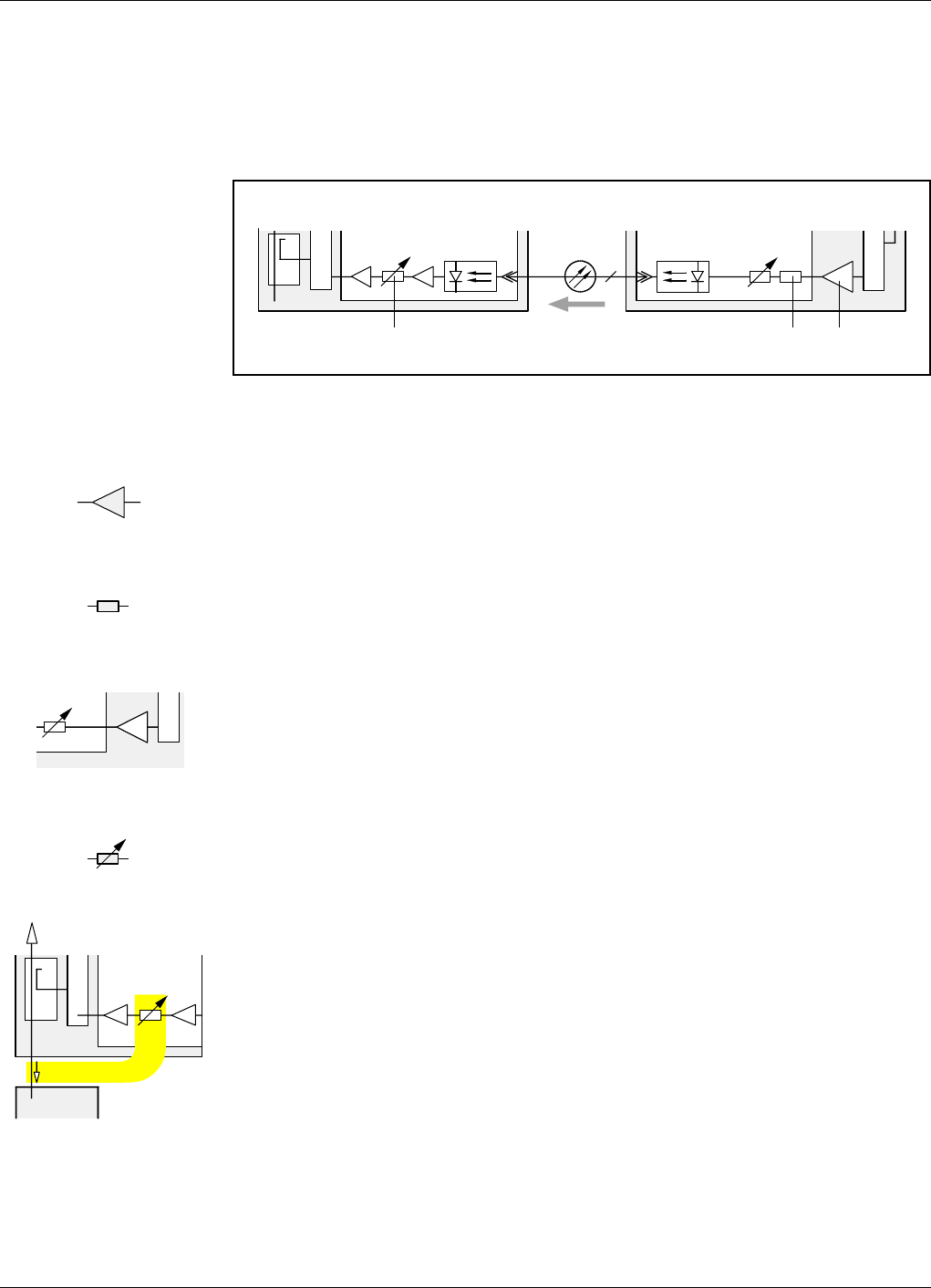
Uplink RF Signal Path
The uplink RF modulated signal path, from the repeater service antenna to the BTS, is
shown in Figure 4-5. The item numbers in the figure are described below. Item numbers
are omitted for those items that have the same function and settings as in the downlink
path.
Figure 4-5. Uplink RF transmission path
1. Repeater amplifier
The repeater amplifier is the same as the downlink amplifier, but in this case the output
power should be adjusted to match the FON input power range, 10 – 36dBm.
2. Power attenuator
The input 16dB/8W power attenuator is the same as the downlink amplifier, but in this
case an alternative configuration can be used.
In the alternative configuration a FON unit without this power attenuator is used. In this
case a lower output power from the FOR unit is fed directly to the following adjustable
attenuator.
The advantage of this configuration is less signal noise.
3. Software adjustable attenuator
The software adjustable 0 – 20dB attenuator is set manually via an O&M software. This
is described in the FON section of the VM100 01/EN, OM-Online, User’s Manual.
If the BTS has a larger coverage area than the repeater, then the attenuator is usually
adjusted to a total uplink gain to the BTS of –10dB (shown in the figure).
If the coverage area is the same for the BTS and the repeater, then the BTS antenna input
sensitivity with connected repeater should be the same as the sensitivity at the repeater
antenna input.
The total uplink gain can, however, not be set only on the software adjustable attenuator
but has to be balanced on the three uplink set points highlighted in Figure 4-6 (see the
next section).
FON
FON
DC
DPX
1TX
RX
312
DPX
UL
FOR
BMU
16dB, 8W
DPX
0 – 20dB
DPX
DC
BMU
FON
BTS
–10dB
Powerwave Fiber Optics
VM100 56/EN – User’s Manual Rev. P1A9-Draft 2004-11 4 - 9
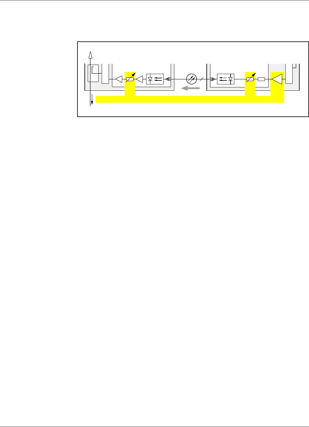
Setting the total uplink gain
The three uplink set points, highlighted in Figure 4-6, have to be balanced to a total
uplink gain appropriate to the ratio of the coverage areas for the BTS and the repeater.
Figure 4-6. Total uplink gain setting points
Coupling factors and power losses in the entire uplink chain, including the optic fiber,
have also to be considered when setting the total uplink gain.
A power calculator should be used when determining the uplink settings.
Some examples with various settings are found in Chapter 6,Commissioning.
FON
FON
DC
DPX
1TX
RX
–10dB
DPX
UL
FOR
BMU
Fiber Optics Powerwave
4 - 10 Rev. P1A9-Draft 2004-11 VM100 56/EN – User’s Manual
FOU, Fiber Optic Unit
The FOU, Fiber Optic Unit, is a complete unit for fiber optic interconnection of two or
more repeaters. It is built up on a flanged plate and can be inserted in all types of LGP
Allgon AR repeaters. In the simpliest configuration, it contains a FON board and a DPX
filter.
Figure 4-7 shows a simple configured FOU, Fiber Optic Unit.
Figure 4-7. The FOU, Fiber Optic Unit
An FOU inserted in the BMU and in the FOR is shown in Figure 4-8.
Figure 4-8. FOU inserted in the BMU and FOR
The FOU can also be configured with optical splitters for more than one FOR in the
optical network, and with WDMs for optical duplex transmission.
FOU
FON
TX
RX
DPX
FOU
BTS
FON
BMU
FON
FOR
1
1
TX
TX
RX
RX
DPX
DC
DPX
FOU
DPX
Powerwave Fiber Optics
VM100 56/EN – User’s Manual Rev. P1A9-Draft 2004-11 4 - 11
Noise, Intermodulation and Dynamic Signal Range
This section contains brief descriptions of noise, intermodulation, and dynamic signal
range.
Noise and intermodulation
Figure 4-9 shows noise and intermodulation values for the optical transmission.
Figure 4-9. Noise and intermodulation
If the fiber loss, LFO, is lower than 5dB, the output noise figure, NFOUT, is determined
by the optical transmitter (’1’ in Figure 4-9).
If the fiber loss, LFO, is higher than 5dB, the output noise figure, NFOUT, is determined
by the receiver amplifier (2).
Intermodulation and IP3
The third order of intermodulation is illustrated on a frequency axis in the figure.
The formula for it reads: IM3 = 3P0 – 2IP3 dB
where:
IM3= Intermodulation level.
P0= Carrier power.
IP3=The IP
3 point of the amplifier.
The IP3 values from the various types of repeater amplifiers are:
BSA 54dBm
CHA 68dBm for 2 channels, 65dBm for 4 channels.
ALR 48dBm (compact repeater and RH)
WRH 35dBm
Dynamic signal range
The dynamic range for the RF signal is determined by the noise level and the IM
requirements. The dynamic range is represented by a vertical arrow in the figure, where:
P=Power
S=Signal level.
N = Noise floor + intermodulation.
FON
1RX
LFO FON
NF = 3 – 4dB
TX
NF = 30 – 35dB
IP3 = 30 – 35dBm
NFOUT
12
Gain 30dBConversion loss 25dB
2f1–f2f1f22f2–f1
DPX
P
S
N
Fiber Optics Powerwave
4 - 12 Rev. P1A9-Draft 2004-11 VM100 56/EN – User’s Manual
Simplex Transmission
This section contains two examples of simplex transmission over fiber.
Figure 4-10. Simplex transmission between an RMU and a FOR unit
The first example, shown in Figure 4-10, illustrates a simple configuration. This
configuration is described in the previous sections in this chapter, but in this case an
RMU is used for radio transmission with the BTS.
The downlink and uplink wavelength is 1310nm.
Figure 4-11. Simplex transmission between a BMU and four FOR units
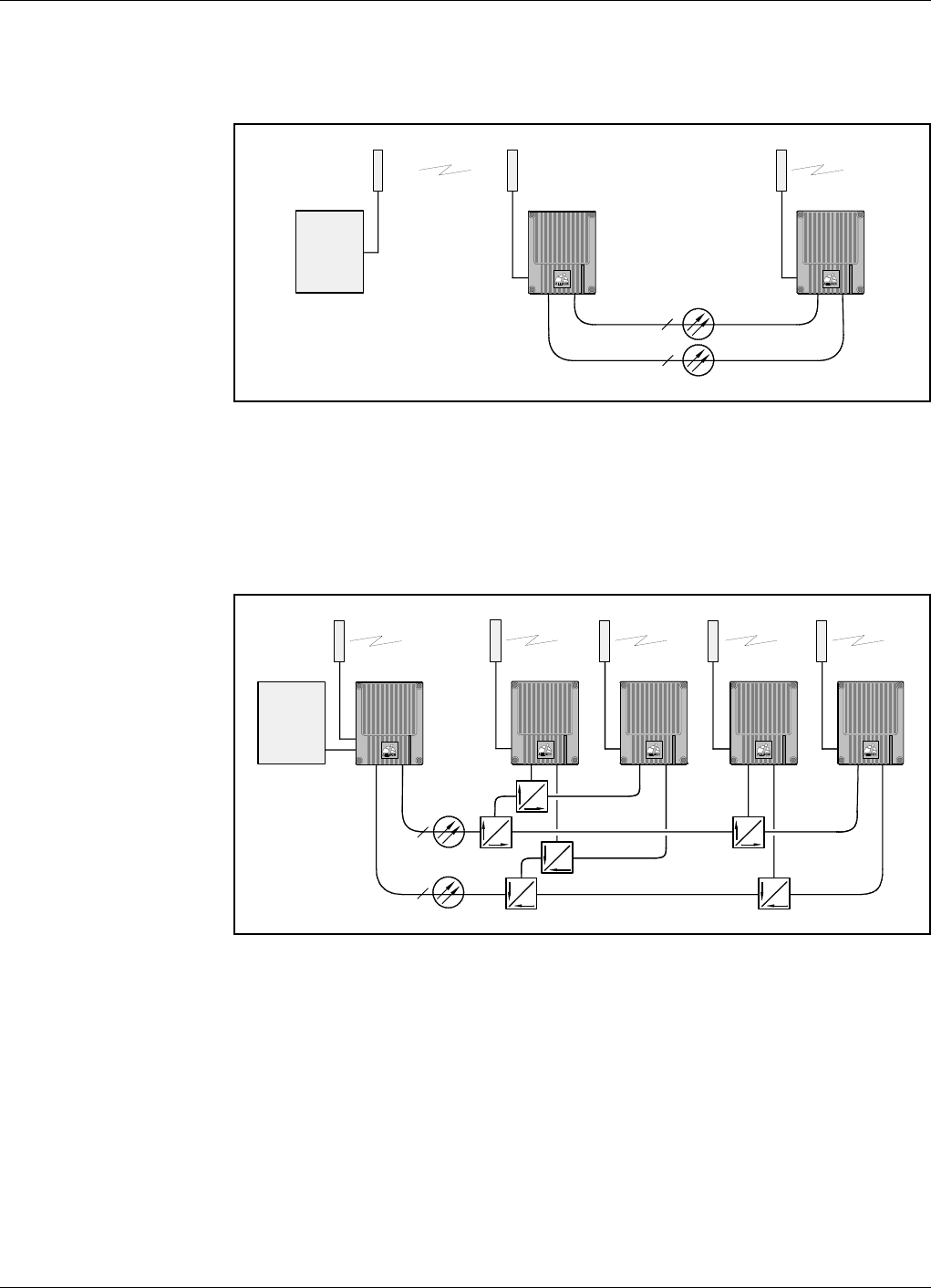
The second example, shown in Figure 4-11, illustrates a BMU and four FOR units
connected via optical splitters in a star configuration. Downlink and uplink wavelength
is 1310nm.
The optical power loss for an optical 50/50 splitter is 3dB. Additional connectors add a
loss of 0.5dB each. Due to the power sharing, up to approximately four slave nodes
(FOR) can be connected to a master FON unit (BMU). For additional slave nodes,
another FON unit has to be inserted in the BMU.
The optical splitters are usually included in the FOU located in the BMU. Figure 4-11
shows, schematically, these parts outside the BMU cabinet.
1
1
RMU FOR
DL UL
BTS
DL = 1310nm
UL = 1310nm
1
1
BMU FOR
DL UL
BTS
FOR
UL
FOR
UL
50
50
FOR
50
50
50
50
50
50
50
50
50
50
DL = 1310nm
UL = 1310nm
UL
Powerwave Fiber Optics
VM100 56/EN – User’s Manual Rev. P1A9-Draft 2004-11 4 - 13
Duplex Transmission
This section contains two examples of full-duplex transmission over fiber.
Figure 4-12. Duplex transmission between an RMU and a FOR unit
The first example, shown in Figure 4-12, illustrates the same repeater configuration as
in the previous section, but now with full-duplex over one fiber achieved by using an
optical WDM (DX O) in each repeater.
The downlink wavelength is 1550nm, the uplink wavelength is 1310nm.
The power loss for an optical WDM is 1dB. Additional connectors add the loss by 0.5dB
each.
The WDMs are included in the FOUs.
Figure 4-13. Duplex transmission between a BMU and three FOR units
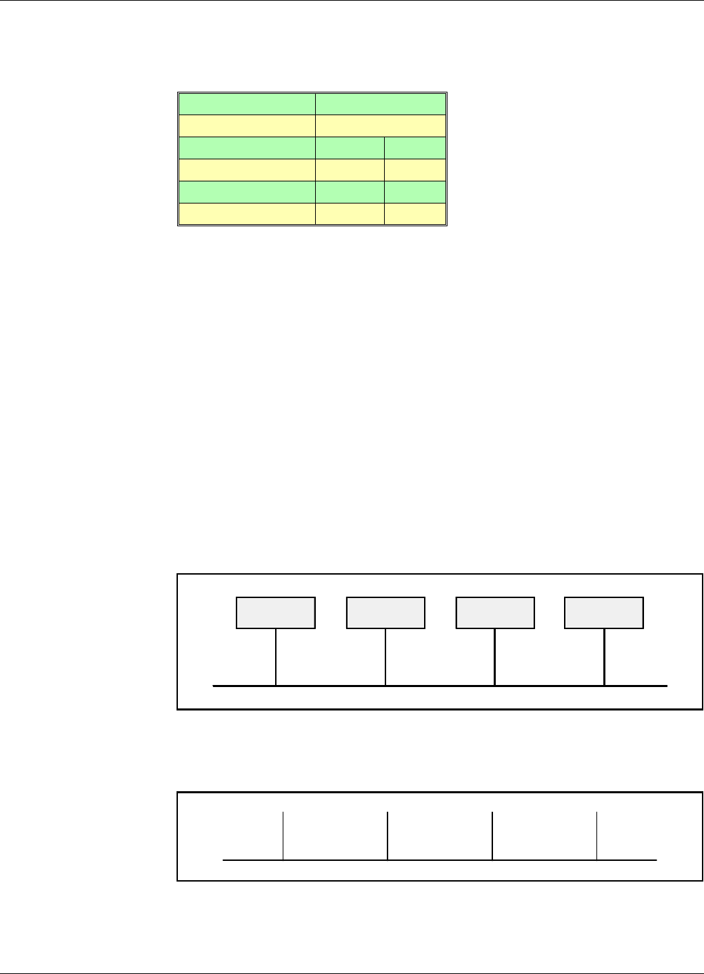
The second example, shown in Figure 4-13, illustrates a BMU and three FOR units
interconnected via optical splitters in a chain configuration. Full-duplex over one fiber
is achieved by using an optical WDM (DX O) in each repeater node.
The downlink wavelength is 1550nm, the uplink wavelengths are 1308nm, 1310nm, and
1312nm from the three slave nodes (FOR).
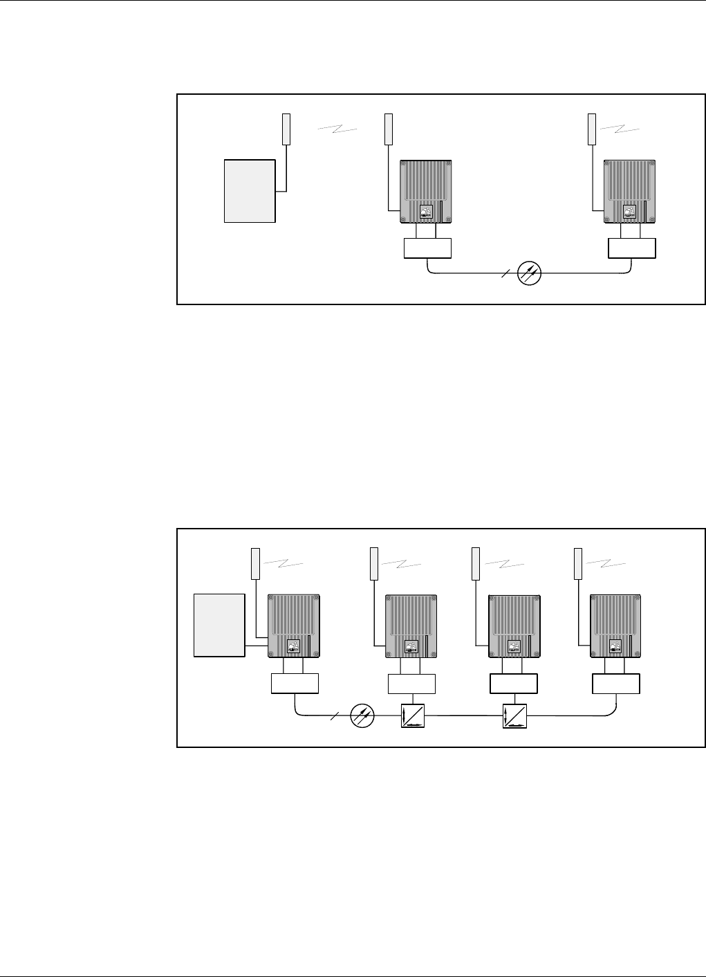
1
RMU FOR
DL UL
BTS
DL = 1550nm
UL = 1310nm
DX O
DX O
1
BMU
DL 1550nm
BTS
FOR
UL 1308nm
FOR
UL 1310nm
30
70
FOR
UL 1312nm
DX ODX O
DX O
DX O
50
50

Fiber Optics Powerwave
4 - 14 Rev. P1A9-Draft 2004-11 VM100 56/EN – User’s Manual
The optical power loss for an optical 30/70 percent splitter is 5.2dB/1.5dB, for a 50/50
percent splitter 3dB. The power loss for an optical WDM is 1dB. Additional connectors
add the loss by 0.5dB each. Due to the power sharing, up to approximately four slave
nodes (FOR) can be connected to a master FON unit (BMU). For additional slave nodes,
another FON unit has to be inserted in the BMU.
The optical WDMs and splitters are usually included in the FOU located in the BMU.
Figure 4-13 shows, schematically, these parts outside the BMU cabinet.

Powerwave Fiber Optics
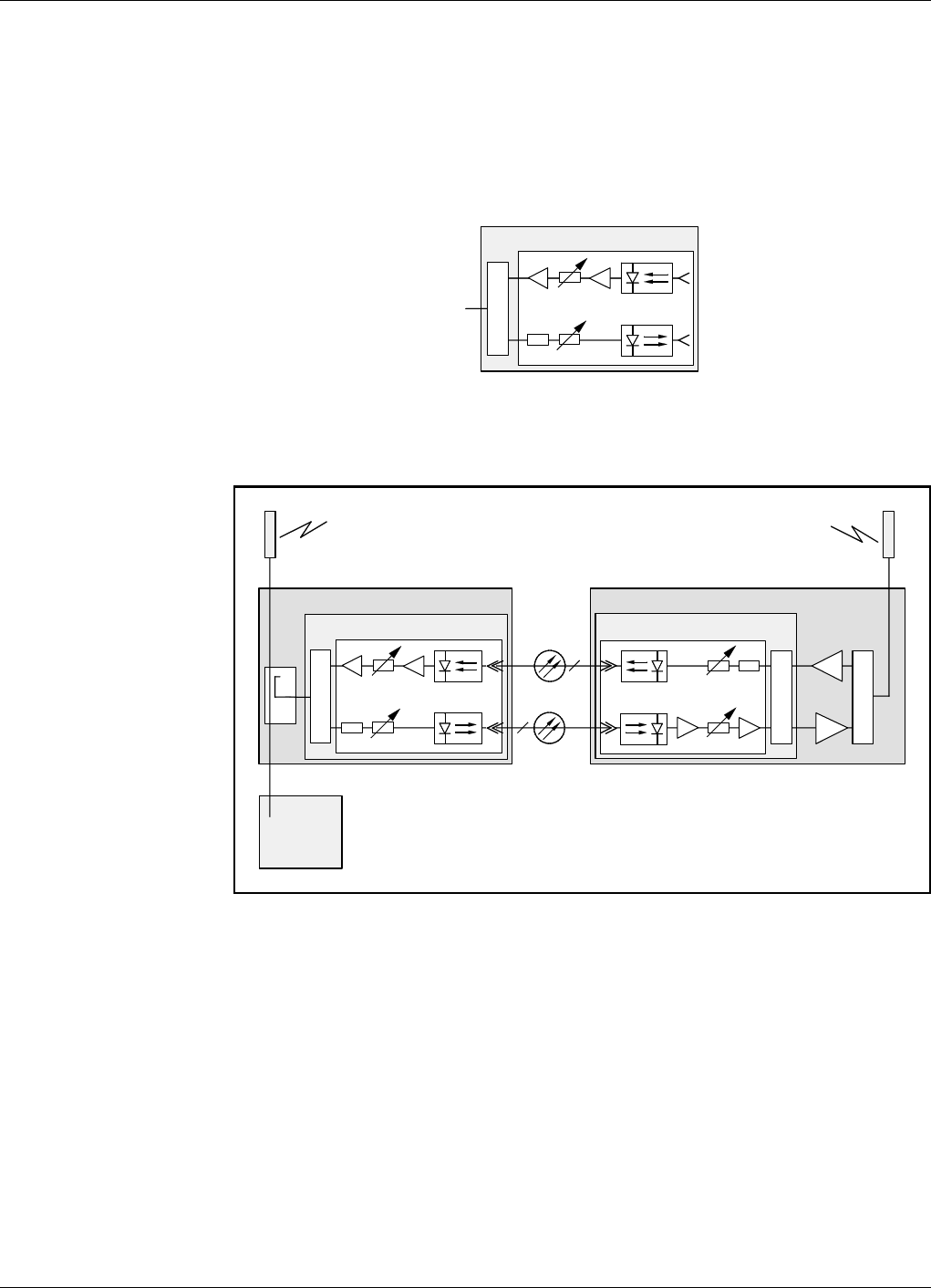
VM100 56/EN – User’s Manual Rev. P1A9-Draft 2004-11 5 - 1
5. IP Over Fiber
IP (Internet Protocol) network is the latest Powerwave network type with UDP/IP
protocol and many features, such as wire or fiber connection, PPP, routing capabilities
for many sub networks, etc.
IP network communication includes communication between network nodes as well as
communication between gateway nodes, for instance FON units, and an O&M software.
Communication can be initiated either by an O&M software or a network node.
When initiated by an O&M software, an operator connects to the network and logs on
to the desired node. An OMS station can also initiate scheduled communication that
automatically connects to the network and logs on to a node.
A network node initiates communication when an alarm is to be transferred, normally to
an OMS station. It also initiates communication if callback is required in a logon
session.
All operation and maintenance of repeaters and remote hubs are carried out via an O&M
software connected to a network. There are two network types that can be used for this
purpose, IP network and R2R network.
This chapter describes IP networks only and is focused on fiber networks.
IP networks over wire and R2R networks are described in the VM100 01/EN, OM-
Online, User’s Manual. This manual also contains further information about IP
networks, IP address planning, and network configuration.
This chapter is divided into the following main parts:
•Terminology for IP networks, page 5-2.
•Hardware and software requirements for IP networks, page 5-3.
•Fiber optic network characteristics, page 5-4.
•Node units in IP networks, page 5-5.
•Net interfaces of the FON unit, page 5-6.
•An example of a network, page 5-7.
Fiber Optics Powerwave
5 - 2 Rev. P1A9-Draft 2004-11 VM100 56/EN – User’s Manual
IP Network Terminology
In the descriptions of the IP network the terminology in the following table is used.
Abbreviations
IP Internet Protocol.
W-net Wire network.
F-net Fiber network.
W-link Wire link.
F-link Fiber link.
WLI Wire Link Interface.
FLI Fiber Link Interface.
Other abbreviations used in this manual are found in the Abbreviations section in the
beginning of this manual.
Net and Link
The following two figures show what a net means and what a link means in this manual.
Figure 5-1 shows a W-net or F-net with WLI or FLI interface respectively.
Figure 5-1. W-net or F-net
Figure 5-2 shows a W-link or F-link with WLI or FLI interface respectively.
Figure 5-2. W-link or F-link
Network type IP
Protocol IP
Network name W-net F-net
Link name W-link F-link
Link media Wire Fiber
Link interface WLI FLI
FON FON FON FON

Powerwave Fiber Optics
VM100 56/EN – User’s Manual Rev. P1A9-Draft 2004-11 5 - 3
Requirements
To be able to use an IP network, the FON hardware and software stated below is
required. Hardware and software that does not meet the requirements below can be
upgraded.
FON hardware
FON board K129.
FON software
FON SA102 05/1 version R1A or higher.
O&M software versions
An OM-Online, OMT32, or OMS station intended to be used on an IP network requires
the following software versions:
OM-Online SA102 60/1 version R1A or higher.
OMT32 SA102 51/3 version R2A or higher.
OMS SA102 54/1 version R2A or higher.
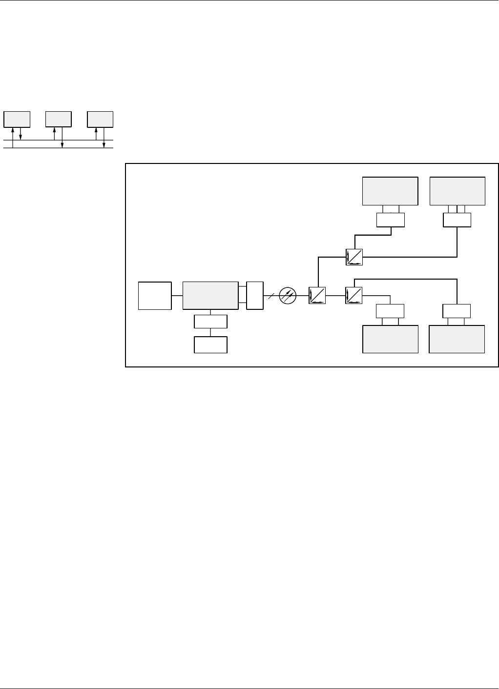
Fiber Optics Powerwave
5 - 4 Rev. P1A9-Draft 2004-11 VM100 56/EN – User’s Manual
F-Net Characteristics
The IP communication signal in an F-net is modulated on a sub carrier below the RF
modulated signal.
The communication transfer rate is 66Kb per second.
F-net can be built up with separate downlink and uplink fibers, multi-drop link
communication, and a dedicated master node and slave nodes (M and S respectively in
the left figure).
F-net can also be built up with single fiber and full-duplex transmission, see Figure 5-3.
Figure 5-3. Single fiber network with five nodes
The network shown in Figure 5-3 has optical WDMs (DX O) in each node, which makes
it possible to use one downlink wavelength and four different uplink wavelengths in the
same fiber.
An F-net contains one master node (the left FON unit in Figure 5-3) and it can contain
up to approximately four slave nodes (the right FON units) due to the signal power
sharing in the optical splitters. In Figure 5-3 there are three 50/50 percent splitters that
reduce the signal power to each of the four slave nodes to 25% of the initial signal power.
In Figure 5-3, the master node is a gateway by means of an RCC. It can communicate
with an O&M software via modem.
The left FON node (CS) only shall be configured with Control Station Capability and
thus be the master unit. None of the other FON nodes are allowed to have the Control
Station Capability because it is a master/slave network. Only one node is allowed to
speak at the same time.
Control Station Capability is described in the VM100 01/EN, OM-Online, User’s
Manual.
FO
M S S
FON FON FON
FON FON
RCC
50
50
PSTN
BTS 1
DX ODX O
FON
DX ODX O
DX
O
FON
CS
50
50
50
50
FON
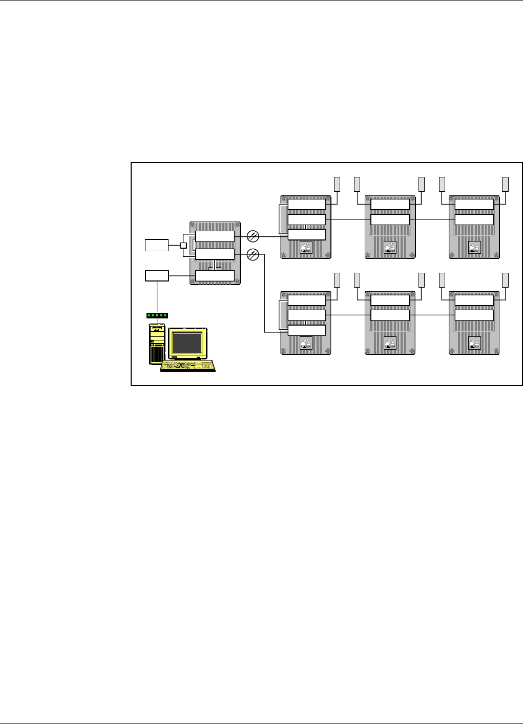
Powerwave Fiber Optics
VM100 56/EN – User’s Manual Rev. P1A9-Draft 2004-11 5 - 5
Node Units
This section describes an example of node units used for communication between an
O&M software and the nodes in a network.
A PC workstation loaded with the O&M software and configured with a modem can be
connected to all nodes that have an RCC (or RCU) and communicate with other units in
connected W-nets and F-nets.
Figure 5-4 shows an O&M workstation connected to an F-net, which is also connected
to two W-nets.
Figure 5-4. O&M workstation connected to an F/W-net
The fibers between the BMU and the FOR units are used for both RF transmission and
network communication.
An internal backbone W-net in the BMU interconnects the FON units.
The two FOR units are also included in two W-nets together with two additional
repeaters in each of these W-nets.
The O&M workstation in Figure 5-4 can communicate with any of the seven units (one
BMU and six repeaters) included in the F-nets and W-nets.
RCC
BSC/CU
BSC/CU
RF
RF
RF
RF
RF
BMU
FOR
FON
FON
RF
FON
RF
FON
RF
RF BSC/CU
BSC/CU
BSC/CU
BSC/CU
FOR
PSTN
BTS
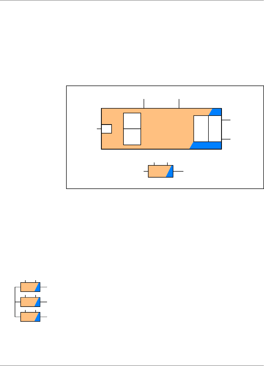
Fiber Optics Powerwave
5 - 6 Rev. P1A9-Draft 2004-11 VM100 56/EN – User’s Manual
The FON Unit Net Interfaces
This section describes the FON unit in networks, one of the most important subunits in
repeater networks. The FON unit is here described as a block with network interfaces.
The FON board contains all software and protocols required for both W-net and F-net
communication, routing included. A sole FON board can be a complete node in an F-net
or W-net.
Figure 5-5 shows the FON board with the communication interfaces pointed out. The
figure shows also some of the most important function blocks on the FON board. The
small figure is a simplified block symbol of the FON board.
Figure 5-5. FON with communication interfaces
The CPU unit with loaded software (SW) controls the FON unit including the network
communication. The RF block in Figure 5-5 converts electrical signals to optical signals
and vice versa.
The local port is used for cable connection between the FON unit and an O&M
workstation. PPP is used for communication via this port.
The remote port is used for remote connection between the FON unit and an O&M
workstation via modem. PPP is used for communication via this port.
WLI is the communication port for W-net.
FLI is the communication port for F-net. In Figure 5-5, this part of the FON board is
marked to indicate an optical part.
The W-net and F-net are interconnected in the FON board, which makes it possible to
interconnect several F-nets via a W-net, see the small figure.
FON FLI
RX
TX
WLI RF
CPU
SW
FON FO
FO
FO
Local Remote
W-net F-net
FON
FON
FON
FO
FO
FO
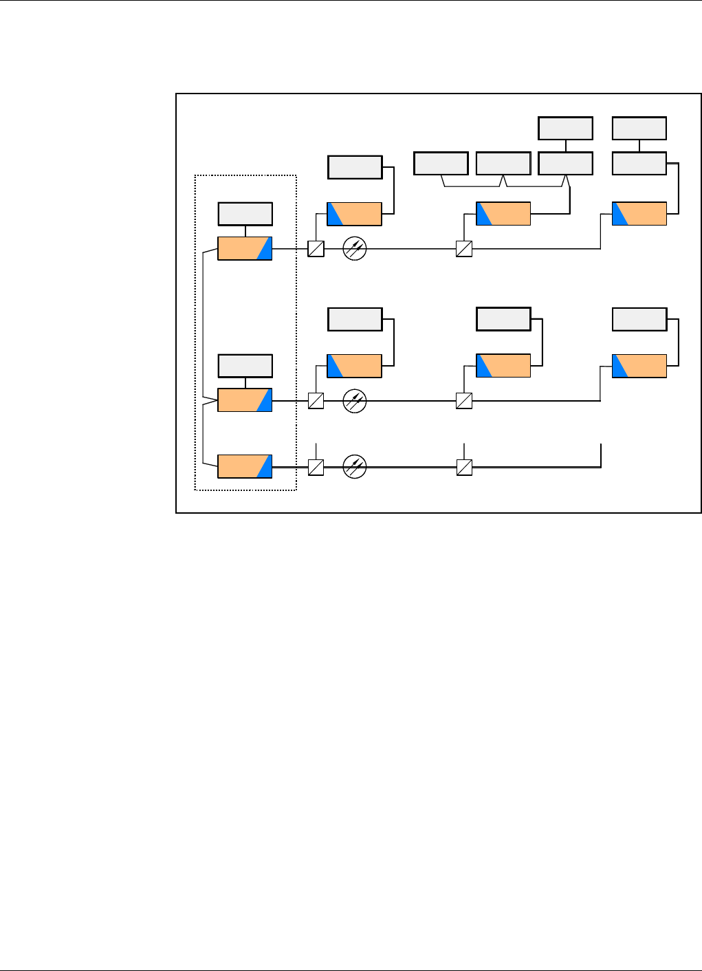
Powerwave Fiber Optics
VM100 56/EN – User’s Manual Rev. P1A9-Draft 2004-11 5 - 7
Network Example
An example of a repeater network with FON units is shown in Figure 5-6.
Figure 5-6. Repeater network example
This network has a BMU with three FON units as F-net master nodes. Two of which are
gateway units. A backbone W-net interconnects the three FON units.
The three F-subnets (FLI) are connected to slave FON nodes via optical splitters. These
slave FON nodes are connected to compact repeaters (BSC) and standard repeaters (CU)
via W-subnets (WLI).
In this network there are four gateways connected to an RCU or RCC unit.
Further information about IP networks, IP address planning, and network configuration
is found in the VM100 01/EN, OM-Online, User’s Manual.
RCC
RCC
BMU/OCM
BSC
WLI
WLI
FLI
FLI
FLI
WLI
FO
FON
FO
FO
FON
FON
FON
BSC
WLI
FON
WLI
FON
BSC
WLI
FON
CU
WLI
FON
CU
RCU
BSC BSC
RCC
FON
CU

Fiber Optics Powerwave
5 - 8 Rev. P1A9-Draft 2004-11 VM100 56/EN – User’s Manual

Powerwave Fiber Optics
VM100 56/EN – User’s Manual Rev. P1A9-Draft 2004-11 6 - 1
6. Commissioning
Read carefully Chapter 1,Safety before commissioning the optical system. See also the
safety precautions for the current repeater or hub types.
Check all connections made during the installation. Also, ensure that both the mains
plugs for repeaters equipped with two power supply units are connected to outlets
supplied from the same fuse.
To fulfill the IP65 weather protective requirements, ensure that the cable strain relief
bushings are properly tightened. Also, ensure that the gaskets at the cable inlets on the
cabinet are properly fitted and not damaged.
When the installation is checked, commission the optical system as described in the
following sections:
Equipment required for the commissioning is listed below.
This chapter contains commissioning instructions only. If you want to read descriptions
of the various functions, see the previous chapters in this manual.
Some system configuration examples are found on page 6-6 and the following pages.
If you get problems when commissioning the system, please contact your nearest
Powerwave representative.
Equipment Required
To be able to commissioning an optical system you will need the following:
•Optical power meter.
•Laptop with O&M software and an RS232 serial cable.
•Spectrum analyzer.
•Repeater tools.
•Optical clenaer.
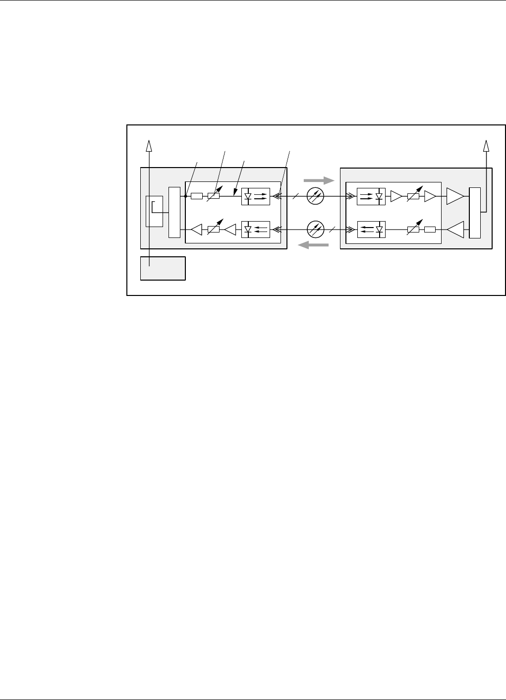
Fiber Optics Powerwave
6 - 2 Rev. P1A9-Draft 2004-11 VM100 56/EN – User’s Manual
Commissioning the Fiber Optic System
Commission the optical transmission system as described in the following instruction.
The instruction covers the optical system only and is therefore applicable to all units
with optical transmission, for instance BMU, RMU, OCM, FOR, and RH.
Figure 6-1 shows a fiber optic system in a BMU and a FOR. These units are also used
as examples in the instruction.
Figure 6-1. Master unit downlink path
Master Unit Downlink Path
1. Make sure the BMU is switched off.
2. Measure the downlink input RF signal power (from the BTS) at the FON board
connector ’P101’ in Figure 6-1 (or at the OCM/BMU 19" rack) using a spectrum
analyzer.
The signal power should be between +10dBm and +36dBm.
Write down the measured power value.
3. Switch the BMU on and wait until it is in operational mode.
4. Connect the O&M software to the FON board.
5. Measure the optical output power from the FON board (TX) using an optical
power meter.
If there is only one slave unit on a short distance, choose the low power range.
Otherwise, keep the default high power range.
If you are in doubt, choose high power and, if needed, change to low power if the
received optical power is more than 4dBm at the slave unit.
6. Set the transmitter attenuation (TX Att.) to a value that gives the following optical
transmitter an input power of approximately 0dBm. The attenuation is set via the
O&M software (FON configuration).
PP101 – 20dB – XdB = 0dB Meassured RF input signal level at P101 minus 20dB minus XdB attenuation
equals 0dB. X is the attenuation set via O&M software. Write down the
attenuation set.
BTS
BMU
FON
DC FON
FOR
P101
TX Att.
0dBm
TX
1TX
RX
1
TX RX
DPX
UL
DL
DPX
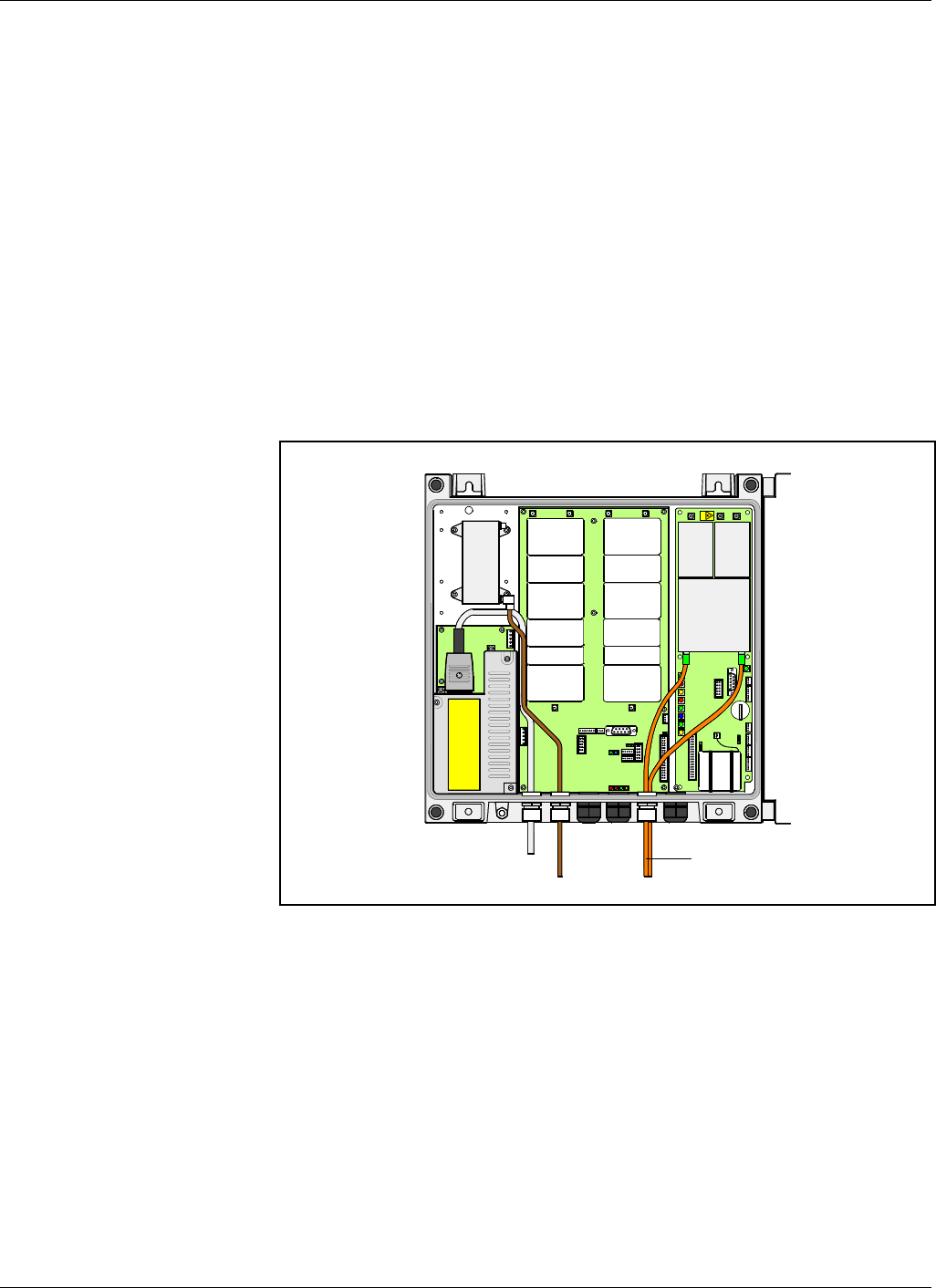
Powerwave Fiber Optics
VM100 56/EN – User’s Manual Rev. P1A9-Draft 2004-11 6 - 3
7. Measure the optical output power from the FON board (TX) using an optical
power meter. Write down the measured power value.
It is recommended to set date and time in the FON units, and to assign names to the units
for future tracking.
Slave Units
Continue by performing the following on each slave unit.
8. Make sure the FOR/slave unit is switched off.
9. If two fibers are used, then make sure the uplink and downlink fibers are connected
correctly in the FOR/slave unit.
The downlink fiber has to be connected to the RX port and the uplink fiber to the
TX port of the FON unit, see Figure 6-2. The FOR in the figure is a compact
repeater.
Figure 6-2. Fiber connection in a slave unit
P102
P130
Beryllium
oxide
hazard
P103
P101
P114
P108
P112
P111
P105
P110
P109
P115
P106
P104
RX
TX
P113
ANT
LO HI
PSM
FON
Fiber optic cables
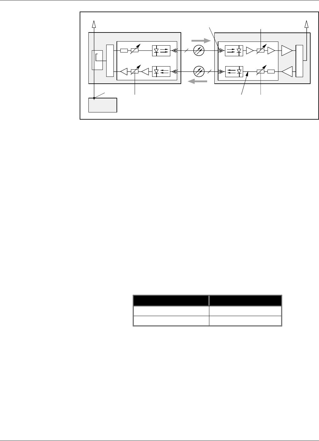
Fiber Optics Powerwave
6 - 4 Rev. P1A9-Draft 2004-11 VM100 56/EN – User’s Manual
Figure 6-3. Slave unit downlink path, and uplink path
10. Switch the FOR on and wait until it is in operational mode.
11. Connect an O&M software to the FON board.
12. Measure the optical downlink input power (’RX’ in Figure 6-3). The receiver level
is measured via the O&M software (FON status).
Write down the measured optical power value.
13. Calculate the optical power loss from the TX port of the master FON board
(step 5) to the RX port of the FOR/slave unit (step 12).
The loss includes fibers, WDMs, splitters, and connectors used in the current
configuration.
The calculated optical loss should not exceed 15dB.
Write down the calculated optical loss value.
14. Set the receiver attenuation (RX Att.) via the O&M software (FON configuration).
An approximate receiver attenuation value can be set according to the calculated
loss over the fiber in step 13. Choose value from the table.
15. Move the O&M software from the FON board to the repeater and set the desired
repeater bandwidth and downlink gain.
16. Move the O&M software back to the FON board and set the transmitter
attenuation (TX Att.) to a calculated value that gives the following optical
transmitter an input power of approximately 0dBm.
17. Choose optical transmitter output power range via the O&M software as described
in step 6.
FON
FOR
BMU
FON
DC
RX Att.
BTS
RX Att.RX
TX Att.
0dBm
dBm
1TXRX
1
TX RX
UL
DL
DPX
DPX
Optical loss over fiber Receiver attenuation
10dB 10dB
!10dB 5dB

Powerwave Fiber Optics
VM100 56/EN – User’s Manual Rev. P1A9-Draft 2004-11 6 - 5
18. Move the O&M software back to the repeater and set uplink attenuation and gain.
Example of downlink and uplink settings are found in the following table.
The optical system is now ready for operation. A fine-tuning of the system should be
done to get the most out of the system. And, the more nodes in the system the more
reason to balance and fine-tune it.
The following section contains some system configuration examples.
Unit Downlink Uplink
BMU (FON) 5dB att. 10dB att.
FOR (FON) 10dB att. 5dB att.
BMU (RF) 60dB gain 60dB gain
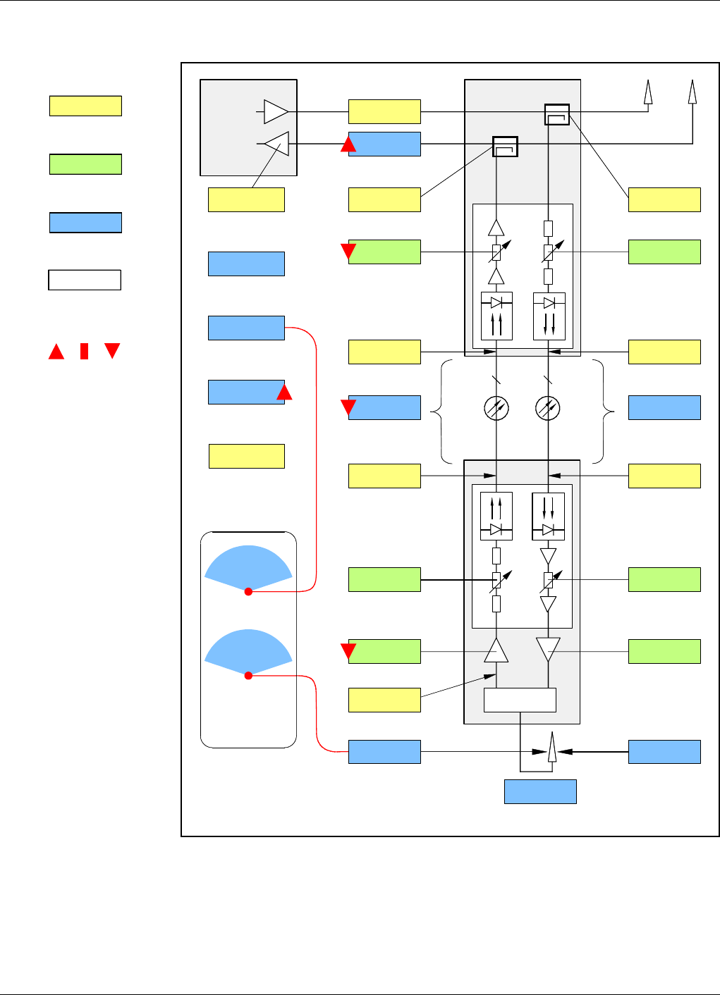
Fiber Optics Powerwave
6 - 6 Rev. P1A9-Draft 2004-11 VM100 56/EN – User’s Manual
System Configuration Examples
Legend:
Fixed values.
Set values via O&M software.
Calculated or resultant values.
Set and resultant UL gain
values in red.
High, medium, and low values
in the example.
Figure 6-4. One FOR, low optical loss, low uplink gain and attenuation
Figure 6-4 shows a FOR connected with low optical loss, low uplink gain and low
uplink attenuation. The BTS sensitivity degradation is high.
High total uplink gain and a BTS sensitivty with repeater very close to the BTS sensitivity
at the repeater antenna indicates a similar coverage area for the BTS and the FOR.
0dB
0dB
0dB
0dB
FON
BTS
BMU
DL
UL
FON
FOR
1 1
DPX
TX level
Total UL gain
RX Att. TX Att.
Fiber/WDM/
splitter loss
TX Att. RX Att.
UL gain DL gain
Repeater noise figure
BTS sensitivity at
repeater antenna
Limited
repeater
TX level
Total DL gain
BTS initial
noise figure
BTS initial
sensitivity
BTS sensitivity
with repeater
BTS sensitivity
degradiation
Number of
repeaters
Fiber/WDM/
splitter loss
Coverage
areas
BTS
FOR
20dB
0dB
20dB
0dB
0dB
40dBm
5dB
–107dBm
14.2dB
1
1.5dBm1.5dBm
1.5dBm 1.5dBm
20dB 20dB
55dB 68dB
–92.9dBm 33dBm
–7dB
5dB
0dB 20dB
–92.8dBm

Powerwave Fiber Optics
VM100 56/EN – User’s Manual Rev. P1A9-Draft 2004-11 6 - 7
Legend:
Fixed values.
Set values via O&M software.
Calculated or resultant values.
Set and resultant UL gain
values in red.
High, medium, and low values
in the example.
Figure 6-5. One FOR, low optical loss, medium uplink gain and attenuation
Figure 6-5 shows a FOR connected with low optical loss, medium uplink gain and
medium uplink attenuation. The BTS sensitivity degradation is low.
High total uplink gain and a BTS sensitivty with repeater very close to the BTS sensitivity
at the repeater antenna indicates a similar coverage area for the BTS and the FOR.
0dB
0dB
0dB
0dB
FON
BTS
BMU
DL
UL
FON
FOR
1 1
DPX
TX level
Total UL gain
RX Att. TX Att.
Fiber/WDM/
splitter loss
TX Att. RX Att.
UL gain DL gain
Repeater noise figure
BTS sensitivity at
repeater antenna
Limited
repeater
TX level
Total DL gain
BTS initial
noise figure
BTS initial
sensitivity
BTS sensitivity
with repeater
BTS sensitivity
degradiation
Number of
repeaters
Fiber/WDM/
splitter loss
Coverage
areas
BTS
FOR
20dB
0dB
20dB
0dB
0dB
40dBm
5dB
–107dBm
3.7dB
1
1.5dBm1.5dBm
1.5dBm 1.5dBm
20dB 20dB
75dB 68dB
–103.9dBm 33dBm
–7dB
5dB
20dB 20dB
–103.3dBm
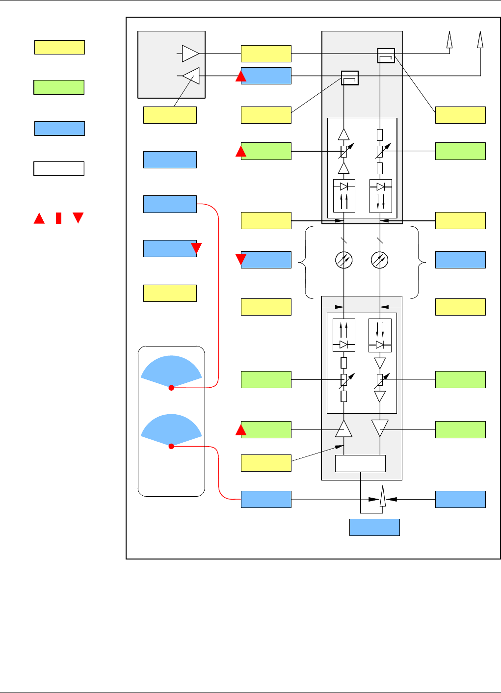
Fiber Optics Powerwave
6 - 8 Rev. P1A9-Draft 2004-11 VM100 56/EN – User’s Manual
Legend:
Fixed values.
Set values via O&M software.
Calculated or resultant values.
Set and resultant UL gain
values in red.
High, medium, and low values
in the example.
Figure 6-6. One FOR, low optical loss, high uplink gain and attenuation
Figure 6-6 shows a FOR connected with low optical loss, high uplink gain and high
uplink attenuation. The BTS sensitivity degradation is low.
High total uplink gain and a BTS sensitivty with repeater very close to the BTS sensitivity
at the repeater antenna indicates a similar coverage area for the BTS and the FOR.
0dB
0dB
0dB
0dB
FON
BTS
BMU
DL
UL
FON
FOR
1 1
DPX
TX level
Total UL gain
RX Att. TX Att.
Fiber/WDM/
splitter loss
TX Att. RX Att.
UL gain DL gain
Repeater noise figure
BTS sensitivity at
repeater antenna
Limited
repeater
TX level
Total DL gain
BTS initial
noise figure
BTS initial
sensitivity
BTS sensitivity
with repeater
BTS sensitivity
degradiation
Number of
repeaters
Fiber/WDM/
splitter loss
Coverage
areas
BTS
FOR
20dB
10dB
20dB
10dB
0dB
40dBm
5dB
–107dBm
5.7dB
1
1.5dBm–6.5dBm
3.5dBm –8.5dBm
5dB 12dB
65dB 80dB
–104.7dBm 33dBm
–7dB
5dB
5dB 20dB
–101.3dBm
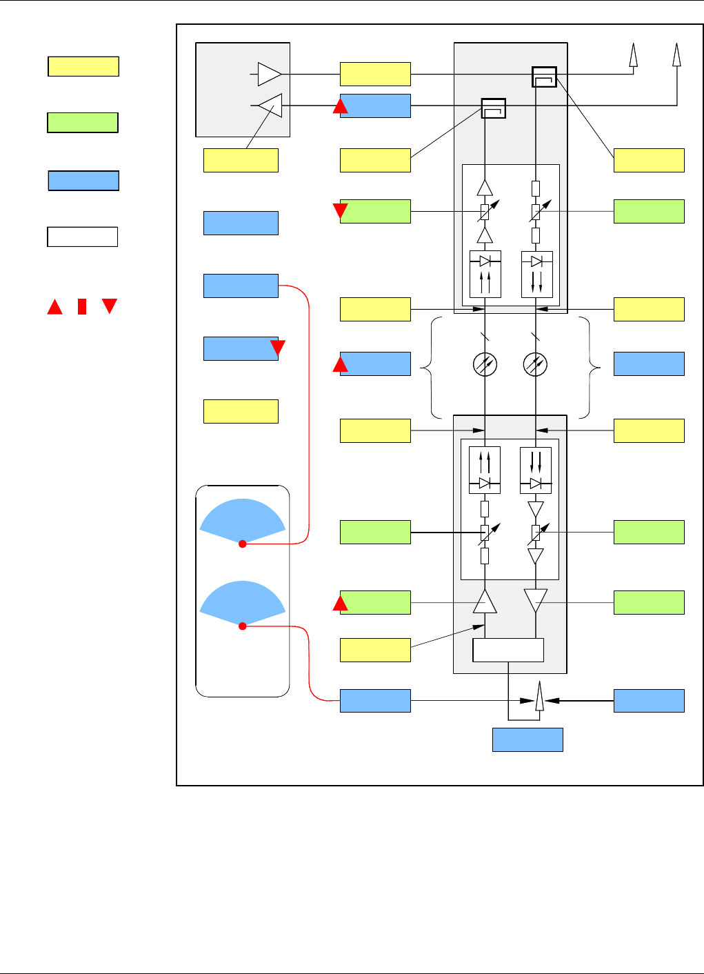
Powerwave Fiber Optics
VM100 56/EN – User’s Manual Rev. P1A9-Draft 2004-11 6 - 9
Legend:
Fixed values.
Set values via O&M software.
Calculated or resultant values.
Set and resultant UL gain
values in red.
High, medium, and low values
in the example.
Figure 6-7. One FOR, high optical loss, high uplink gain
Figure 6-7 shows a FOR connected with high optical loss, high uplink gain and an
uplink attenuation adapted to the optical loss. The BTS sensitivity degradation is low.
High total uplink gain and a BTS sensitivty with repeater very close to the BTS sensitivity
at the repeater antenna indicates a similar coverage area for the BTS and the FOR.
0dB
0dB
0dB
0dB
FON
BTS
BMU
DL
UL
FON
FOR
1 1
DPX
TX level
Total UL gain
RX Att. TX Att.
Fiber/WDM/
splitter loss
TX Att. RX Att.
UL gain DL gain
Repeater noise figure
BTS sensitivity at
repeater antenna
Limited
repeater
TX level
Total DL gain
BTS initial
noise figure
BTS initial
sensitivity
BTS sensitivity
with repeater
BTS sensitivity
degradiation
Number of
repeaters
Fiber/WDM/
splitter loss
Coverage
areas
BTS
FOR
20dB
10dB
20dB
10dB
0dB
40dBm
5dB
–107dBm
3.5dB
1
1.5dBm–8.5dBm
1.5dBm –8,5dBm
10dB 12dB
80dB 80dB
–104.1dBm 33dBm
–7dB
5dB
15dB 20dB
–103.5dBm
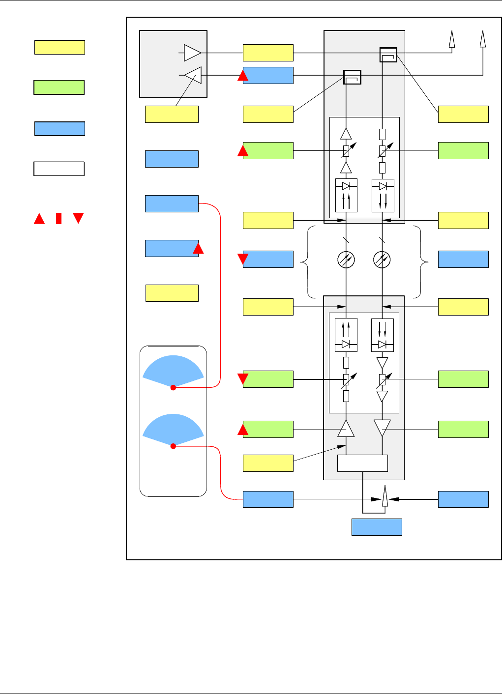
Fiber Optics Powerwave
6 - 10 Rev. P1A9-Draft 2004-11 VM100 56/EN – User’s Manual
Legend:
Fixed values.
Set values via O&M software.
Calculated or resultant values.
Set and resultant UL gain
values in red.
High, medium, and low values
in the example.
Figure 6-8. Nine FORs, low optical loss, high uplink gain and attenuation
Figure 6-8 shows one of nine FORs connected to one of three FON units in the BMU
with low optical loss, high uplink gain and high uplink attenuation. The BTS sensitivity
degradation is high.
High total uplink gain and a BTS sensitivty with repeater very close to the BTS sensitivity
at the repeater antenna indicates a similar coverage area for the BTS and the FOR.
0dB
0dB
0dB
0dB
FON
BTS
BMU
DL
UL
FON
FOR
1 1
DPX
TX level
Total UL gain
RX Att. TX Att.
Fiber/WDM/
splitter loss
TX Att. RX Att.
UL gain DL gain
Repeater noise figure
BTS sensitivity at
repeater antenna
Limited
repeater
TX level
Total DL gain
BTS initial
noise figure
BTS initial
sensitivity
BTS sensitivity
with repeater
BTS sensitivity
degradiation
Number of
repeaters
Fiber/WDM/
splitter loss
Coverage
areas
BTS
FOR
20dB
0dB
20dB
0dB
0dB
40dBm
5dB
–107dBm
15.3dB
9
1.5dBm1.5dBm
1.5dBm 1.5dBm
10dB 20dB
55dB 68dB
–91.8dBm 33dBm
–7dB
5dB
10dB 20dB
–91.7dBm
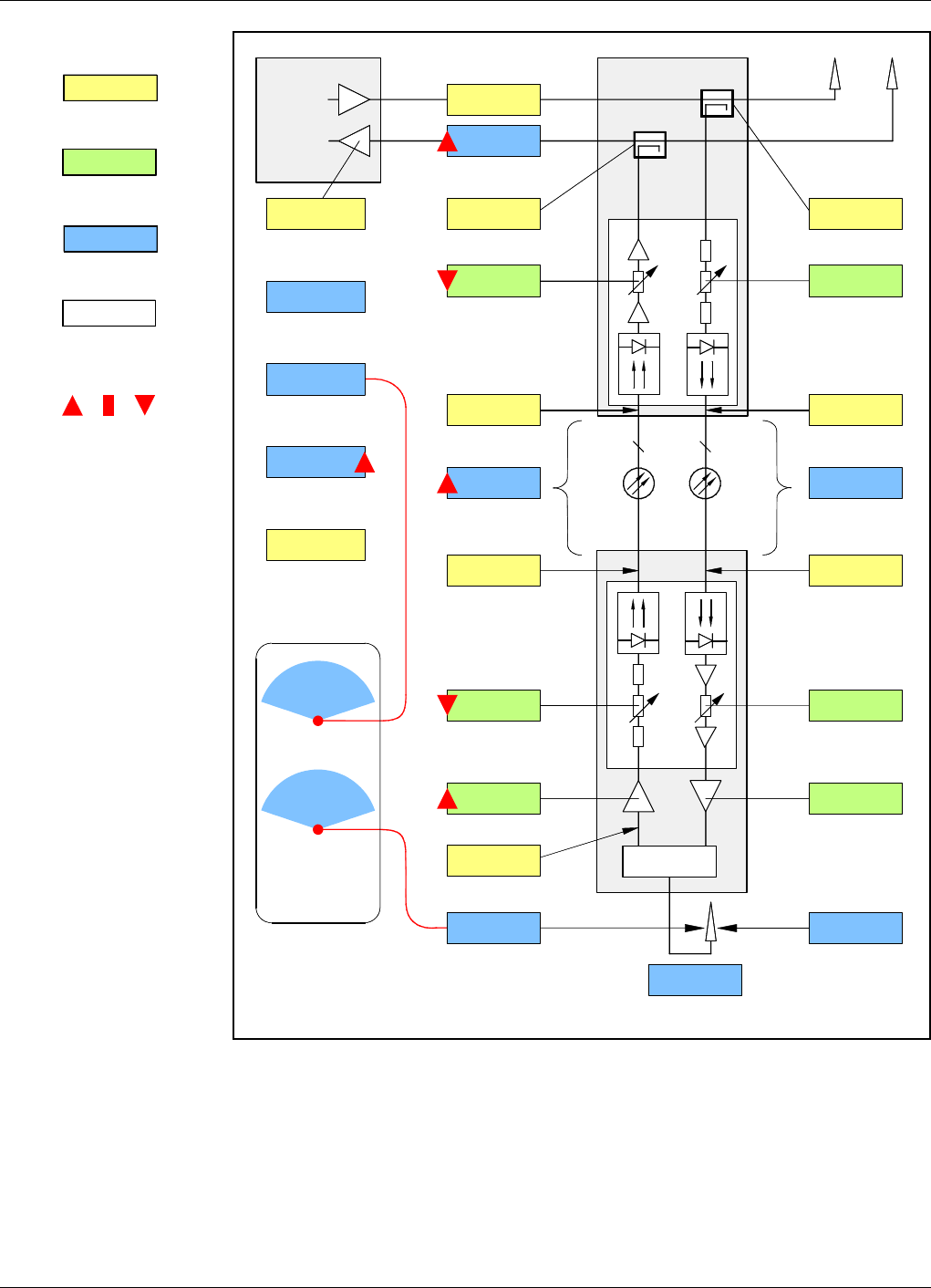
Powerwave Fiber Optics
VM100 56/EN – User’s Manual Rev. P1A9-Draft 2004-11 6 - 11
Legend:
Fixed values.
Set values via O&M software.
Calculated or resultant values.
Set and resultant UL gain
values in red.
High, medium, and low values
in the example.
Figure 6-9. Nine FORs, high optical loss, high total uplink gain
Figure 6-9 shows one of nine FORs connected to one of three FON units in the BMU
with high optical loss, high uplink gain and an uplink attenuation adapted to the optical
loss. The BTS sensitivity degradation is high.
High total uplink gain and a BTS sensitivty with repeater very close to the BTS sensitivity
at the repeater antenna indicates a similar coverage area for the BTS and the FOR.
0dB
0dB
0dB
0dB
FON
BTS
BMU
DL
UL
FON
FOR
1 1
DPX
TX level
Total UL gain
RX Att. TX Att.
Fiber/WDM/
splitter loss
TX Att. RX Att.
UL gain DL gain
Repeater noise figure
BTS sensitivity at
repeater antenna
Limited
repeater
TX level
Total DL gain
BTS initial
noise figure
BTS initial
sensitivity
BTS sensitivity
with repeater
BTS sensitivity
degradiation
Number of
repeaters
Fiber/WDM/
splitter loss
Coverage
areas
BTS
FOR
20dB
10dB
20dB
10dB
0dB
40dBm
5dB
–107dBm
14dB
9
1.5dBm–6dBm
4dBm –8,5dBm
5dB 12dB
65dB 80dB
–93.1dBm 33dBm
–7dB
5dB
5dB 20dB
–93dBm
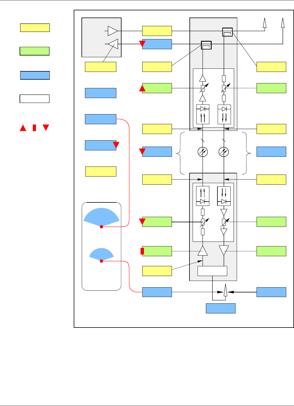
Fiber Optics Powerwave
6 - 12 Rev. P1A9-Draft 2004-11 VM100 56/EN – User’s Manual
Legend:
Fixed values.
Set values via O&M software.
Calculated or resultant values.
Set and resultant UL gain
values in red.
High, medium, and low values
in the example.
Figure 6-10. Nine FORs, low optical loss, low total uplink gain
Figure 6-10 shows one of nine FORs connected to one of three FON units in the BMU
with low optical loss, medium uplink gain and high uplink attenuation. The BTS
sensitivity degradation is low.
Low total uplink gain decreases the BTS sensitivty with repeater under the BTS
sensitivity at the repeater antenna level, indicating a larger coverage area for the BTS
than for the FOR.
0dB
0dB
0dB
0dB
FON
BTS
BMU
DL
UL
FON
FOR
1 1
DPX
TX level
Total UL gain
RX Att. TX Att.
Fiber/WDM/
splitter loss
TX Att. RX Att.
UL gain DL gain
Repeater noise figure
BTS sensitivity at
repeater antenna
Limited
repeater
TX level
Total DL gain
BTS initial
noise figure
BTS initial
sensitivity
BTS sensitivity
with repeater
BTS sensitivity
degradiation
Number of
repeaters
Fiber/WDM/
splitter loss
Coverage
areas
BTS
FOR
20dB
0dB
20dB
0dB
–10dB
40dBm
5dB
–107dBm
7.6dB
9
1.5dBm1.5dBm
1.5dBm 1.5dBm
20dB 20dB
65dB 68dB
–91.5dBm 33dBm
–7dB
5dB
20dB 20dB
–99.4dBm
Powerwave Fiber Optics
VM100 56/EN – User’s Manual Rev. P1A9-Draft 2004-11 6 - 13
Legend:
Fixed values.
Set values via O&M software.
Calculated or resultant values.
Set and resultant UL gain
values in red.
High, medium, and low values
in the example.
Figure 6-11. Nine FORs, high optical loss, low total uplink gain
Figure 6-11 shows one of nine FORs connected to one of three FON units in the BMU
with high optical loss, and an uplink attenuation adapted to the optical loss. The BTS
sensitivity degradation is low.
Low total uplink gain decreases the BTS sensitivty with repeater under the BTS
sensitivity at the repeater antenna level, indicating a larger coverage area for the BTS
than for the FOR.
0dB
0dB
0dB
0dB
FON
BTS
BMU
DL
UL
FON
FOR
1 1
DPX
TX level
Total UL gain
RX Att. TX Att.
Fiber/WDM/
splitter loss
TX Att. RX Att.
UL gain DL gain
Repeater noise figure
BTS sensitivity at
repeater antenna
Limited
repeater
TX level
Total DL gain
BTS initial
noise figure
BTS initial
sensitivity
BTS sensitivity
with repeater
BTS sensitivity
degradiation
Number of
repeaters
Fiber/WDM/
splitter loss
Coverage
areas
BTS
FOR
20dB
10dB
20dB
10dB
–10dB
40dBm
5dB
–107dBm
5.9dB
9
1.5dBm–6dBm
4dBm –8.5dBm
20dB 12dB
85dB 80dB
–93.2dBm 33dBm
–7dB
5dB
20dB 20dB
–101.1dBm

Fiber Optics Powerwave
6 - 14 Rev. P1A9-Draft 2004-11 VM100 56/EN – User’s Manual

Powerwave Fiber Optics
VM100 56/EN – User’s Manual Rev. P1A9-Draft 2004-11 7 - 1
7. Passive Devices
This chapter describes those passive components that are used to build optical fiber
networks with two or more nodes.
These devices are:
•OSP, Optical splitters, page 7-2.
•WDM, wavelength division multiplexers, page 7-4.
•Fiber optic cables, page 7-6.
•Fiber optic connectors, page 7-9.
Fiber Optics Powerwave
7 - 2 Rev. P1A9-Draft 2004-11 VM100 56/EN – User’s Manual
OSP, Optical Splitter
This section describes those types of optical splitters that are used to build repeater fiber
networks. These are variants of three port optical splitters, also called beamsplitters or
tee couplers.
After the general description, the graphic symbol for the optical splitter, and two
examples of splitter usages are found.
Figure 7-1. Three port optical splitter
The optical splitter is used to split an optical signal in a common fiber port into two or
more output fiber ports, and the other way around, that is to combine the signals from
two or more input ports into one common port.
Optical splitters have to be used to interconnect more than two units in a fiber network.
The signal power in the splitter output ports is divided, reducing the signal magnitude in
each of the ports.
The signal magnitude reduction, or power loss, for the common types of optical splitters
for repeater networks are found in the following table.
Additional loss for optical connectors is approximately 0.5dB per connector.
The table indicates that a 50/50 percent splitter divides the signal power from the
common fiber equally between the output fibers. The splitter has the same loss in the
reverse direction.
A 30/70 percent splitter divides the signal power from the common fiber in a part with
30% of the common power and another part with 70% of the common power. The
splitter has the same loss in the reverse direction.
Other types of splitters, such as 90/10, 95/5, and 99/1 percent are not used for repeater
networks.
Splitter type Loss
50/50 percent 3dB for each of the ports due to the specification.
Typical loss is between 3.2dB and 3.5dB.
30/70 percent 5.2dB in the 30% port.
1.5dB in the 70% port.
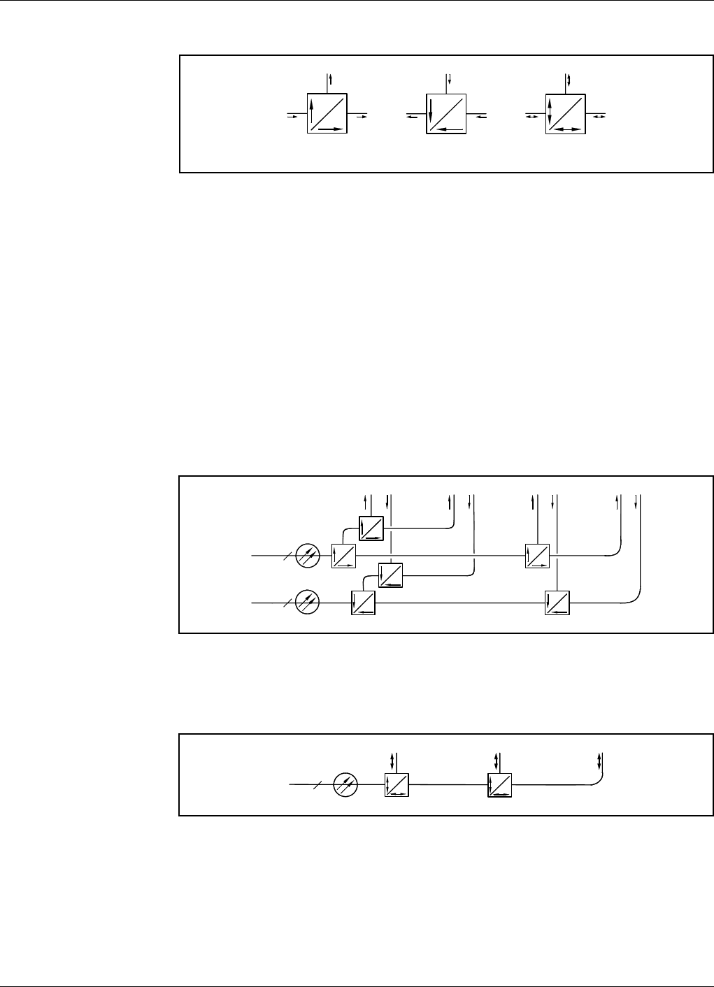
Powerwave Fiber Optics
VM100 56/EN – User’s Manual Rev. P1A9-Draft 2004-11 7 - 3
Graphic Symbol
Figure 7-2. Optical splitter graphic symbol
Figure 7-2 shows the following three variants of an optical splitter graphic symbol
(according to the EIA/TIA-587):
A – A 50/50 percent splitter used for simplex splitting, from the common fiber to the
two output fibers.
B – A 30/70 percent splitter used for simplex combining, from the two input fibers to
the common fiber.
C – A 30/70 percent splitter used for duplex splitting/combining between the
common fiber and the two input/output fibers.
Examples
These examples illustrate two networks using optical splitters.
Figure 7-3. Optical splitters in a simplex network
Figure 7-3 shows a simplex network using optical splitters. The common fiber is divided
into four output parts with 25% of the common power each.
Figure 7-4. Optical splitters in a duplex network
Figure 7-4 shows a duplex network using optical splitters. The common fiber is divided
into three parts with 30 – 35% of the common power each.
ABC
50
50
30
70
70
30
1
1
50
50
50
50
50
50
50
50
50
50
50
50
130
70
50
50
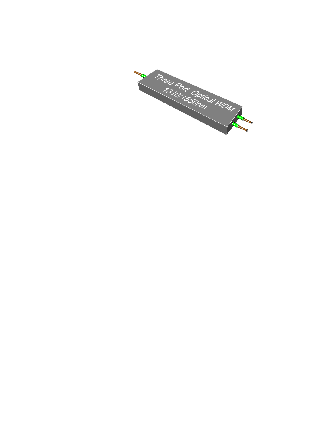
Fiber Optics Powerwave
7 - 4 Rev. P1A9-Draft 2004-11 VM100 56/EN – User’s Manual
WDM, Wavelength Division Multiplexer
This section describes those types of optical multipexers that are used to build repeater
fiber networks. These are 1310nm and 1550nm WDMs.
After the general description, the graphic symbol for the multiplexer, and an example of
WDM usage are found.
Figure 7-5. Three port WDM, Wavelength Division Multiplexer
A WDM is used to split two or more signals of different wavelengths in a common fiber
port into two or more output fiber ports, and the other way round, that is to combine
signals of different wavelengths from two or more input ports into one common port.
The WDM has a very low insertion loss, approximately 1dB. Additional loss for optical
connectors is approximately 0.5dB per port.
The WDM has two important characteristics, crosstalk and channel separation.
•Crosstalk, also called directivity, is the WDM’s ability to separate the demultiplexed
channels. Each channel should appear only in the intended output port, not in any
other output port. The crosstalk or diversity specification is thus a measurement of the
channel isolation.
•Channel separation is the WDM’s ability to distinguish different wavelengths. In
most WDMs, the wavelengths used has to be widely separated.
There are two different ways to use WDMs with 1310 and 1550nm wavelengths. They
can be used for single direction dual signal transmission, or for bi-directional
transmission, see the following sections.
There are WDMs with a channel separation of 2nm, which is shown in the example
further ahead in this section.
There is also a CWDM type (Coarse WDM) that has a channel separation of 20nm. This
type of CWDM with a wider channels spacing can be used for laser emitters that have
high spectral width or thermal drift. CWDM systems support transmission distances up
to 50km.
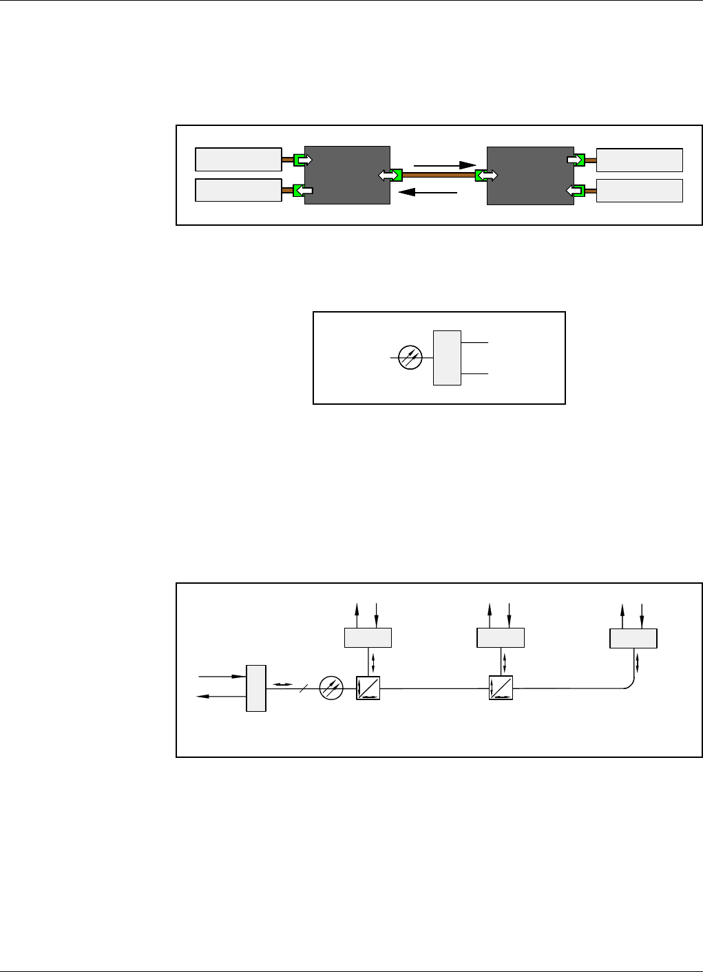
Powerwave Fiber Optics
VM100 56/EN – User’s Manual Rev. P1A9-Draft 2004-11 7 - 5
Bi-directional transmission
Bi-directional, or duplex, transmission can be used to simultaneously communicate in
both directions over the same fiber.
Figure 7-6 shows the principle of this communication type.
Figure 7-6. Bi-directional transmission
Graphic Symbol
Figure 7-7. WDM graphic symbol
Figure 7-7 shows the graphic symbol for the optical WDM, Wavelength Division
Multiplexer (according to the EIA/TIA-587).
Example
This example illustrates a duplex transmission using WDMs and optical splitters.
Figure 7-8. Duplex transmission with WDMs
Figure 7-8 shows a duplex fiber network with different wavelengths for downlink and
uplink. The master unit transmits 1550nm and receives 1308nm, 1310nm, and 1312nm
from the three slave units.
WDM WDM
TX – 1310nm
RX – 1550nm
RX – 1310nm
TX – 1550nm
1310nm
1550nm
DX
O
1
1550nm
1308nm
30
70
DX
O
DX O
50
50
1550nm 1310nm
DX O
1550nm 1312nm
DX O
1550nm
1308nm
1310nm
1312nm
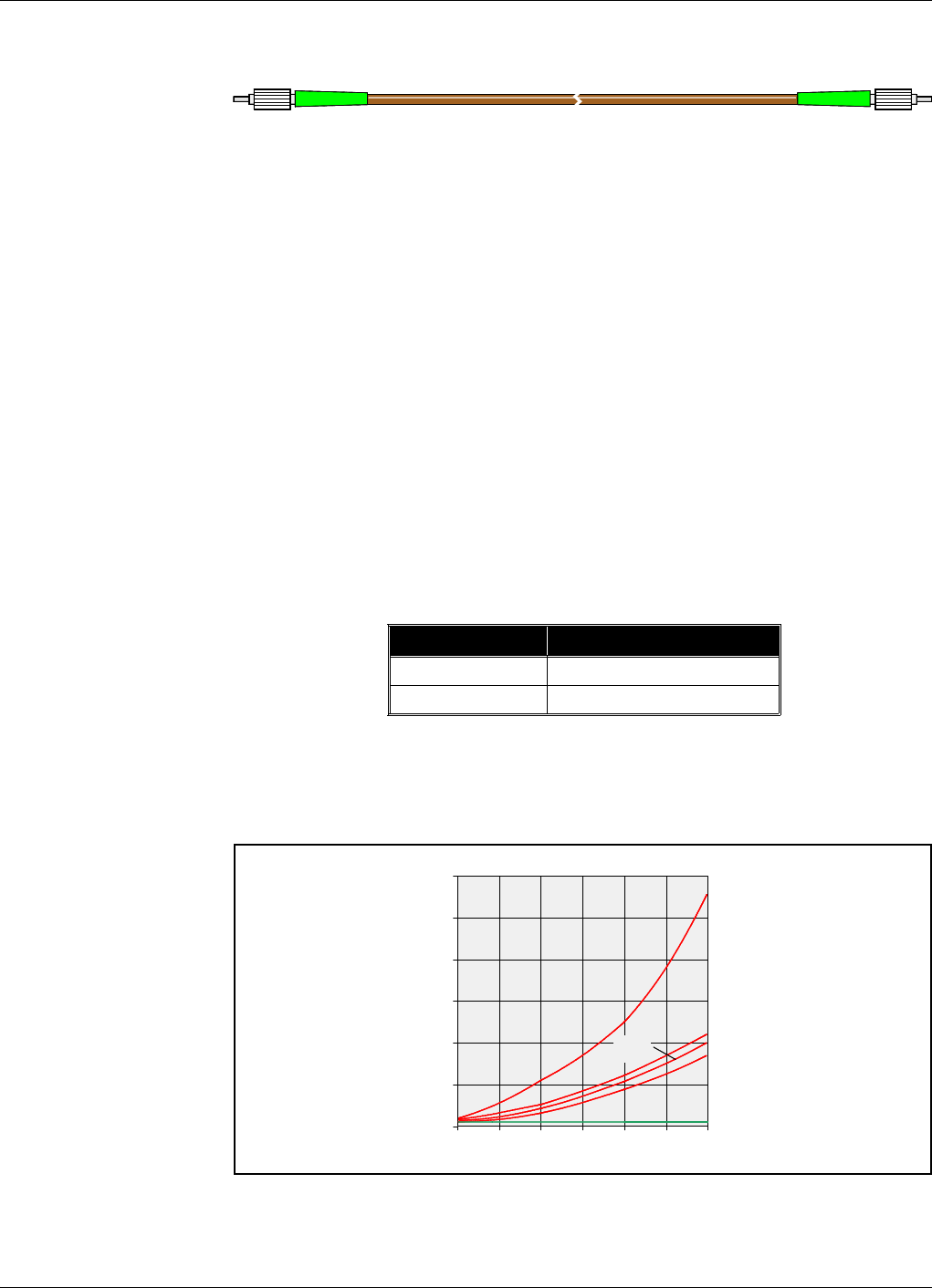
Fiber Optics Powerwave
7 - 6 Rev. P1A9-Draft 2004-11 VM100 56/EN – User’s Manual
Fiber Optic Cables
Fiber optic 9/125µm single-mode patch cables for Powerwave repeaters are normally
delivered with the system.
Recommended backbone cables: Single-mode 9/125µm fiber optic cables.
Single-mode 9/125µm fiber optic cables have a very good bandwidth-distance product
and a low cable loss, see below.
To add cable length, permanent splices are generally used outside buildings while
connectors are generally used inside buildings. Permanent slices are described below,
connectors are described in the next section.
Bandwidth-distance product
The bandwidth-distance product (MHz km) for this cable type is higher than 20,000
for both 1310nm and 1550nm. As a comparison, a 50/125µm multi-mode cable has a
product between 300 and 1,500.
Cable loss
The cable loss is found in the following table.
Additional loss for optical connectors is approximately 0.5dB per connector.
The following diagram illustrates the attenuation differences between some copper
coaxial cables and the single-mode fiber cable.
Figure 7-9. Attenuation for copper coaxial cables and fiber cable
Figure 7-9 shows the attenuation for RG-58, RG-62, RG-11, RG-8, RG-6U and single-
mode fiber (SM).
Wavelength Loss
1310nm 0.35dB per kilometer.
1550nm 0.20dB per kilometer.
0
600
1700 MHz
500
400
300
200
100
10 50 100 200 400
dB/km
RG-58
RG-62
RG-11,
RG-6U
RG-8
SM

Powerwave Fiber Optics
VM100 56/EN – User’s Manual Rev. P1A9-Draft 2004-11 7 - 7
The best of the copper coaxial cables, RG-8, has an attenuation of approximately 100dB/
km at a frequency of 300MHz. This means that only 0.00000001% of the source power
remains after a distance of 1km. In a 1550nm single-mode fiber cable of the same length,
approximately 95% of the source power remains. This example is applicable for a
splice-less cable with no other devices connected.
Miscellaneous fiber cable characteristics
Minimum bend radius for this cable type is 12mm.
The operating temperature range for the most common 9/125µm fiber cabels is –60°C
to +85°C. The lowest temperature causes more trouble than the highest temperature.
Permanent splices
When a fiber cable has to be lengthened, the lowest attenuation and backreflection is
obtained by performing a permanent fiber to fiber splice. Connectors can be used for the
same purpose, but normally they have higher attenuation and backreflection. Permanent
splices are also less expensive.
There are two main types of permanent fiber to fiber splices, fusion splice and
mechanical splice.
Fusion splice
Fusion splice implies that the two cleaved fiber ends are butted together and heated
until they fuse. To be able to perform this type of splice, a fusion splicer is required.
This device has, in addition to an alignment and welding mechanism, also camera
or microscope for supervision of the alignment and fuse procedures, and
instruments to measure the power through the fiber splice.
The attenuation through a correctly performed fusion splice can be as low as
0.05dB.
Mechanical splice
Mechanical splice implies that the two cleaved fiber ends are joined into a structure,
or fixed together with epoxy. To be able to perform this type of splice, a splicer
device is required, which is less expensive than a fusion splicer.
The easiest way to perform a mechanical splice is to use a thin capillary tube in
which the two fiber ends are inserted until they are in contact with each other. This
method is called capillary splicing.
A mechanical splice may have a slightly higher loss and backreflection than a
fusion solice. There is, however, index-matching gel to reduce this loss and
backreflection.

Fiber Optics Powerwave
7 - 8 Rev. P1A9-Draft 2004-11 VM100 56/EN – User’s Manual
Powerwave Patch Cables
Powerwave can provide a number of fiber patch cables with connectors for various
applications. The following list contains some examples of these fiber cables.
As the number of cable lengths and connector combinations grow, please contact your
nearest Powerwave representative for information about currently available cables.
Connector A Connector B Length Part #
DIN/APC DIN/APC 2m PM403 07/4
DIN/APC DIN/APC 5m PM403 07/2
DIN/APC DIN/APC 10m PM403 07/1
DIN/APC DIN/APC 25m PM403 07/3
DIN/APC FC/APC 2m PM403 01/4
DIN/APC FC/APC 5m PM403 01/2
DIN/APC FC/APC 10m PM403 01/1
DIN/APC FC/APC 25m PM403 01/3
DIN/APC FC/PC 2m PM403 02/4
DIN/APC FC/PC 5m PM403 02/3
DIN/APC FC/PC 10m PM403 02/1
DIN/APC FC/PC 25m PM403 02/2
DIN/APC SC/APC 10m PM403 05/1
DIN/APC SC/PC 10m PM403 04/1
DIN/APC ST 2m PM403 03/2
DIN/APC ST 10m PM403 03/1
FC/APC FC/APC 2m PM403 09/1
FC/APC FC/APC 10m PM403 09/2
FC/PC FC/APC 10m PM403 06/1
A B
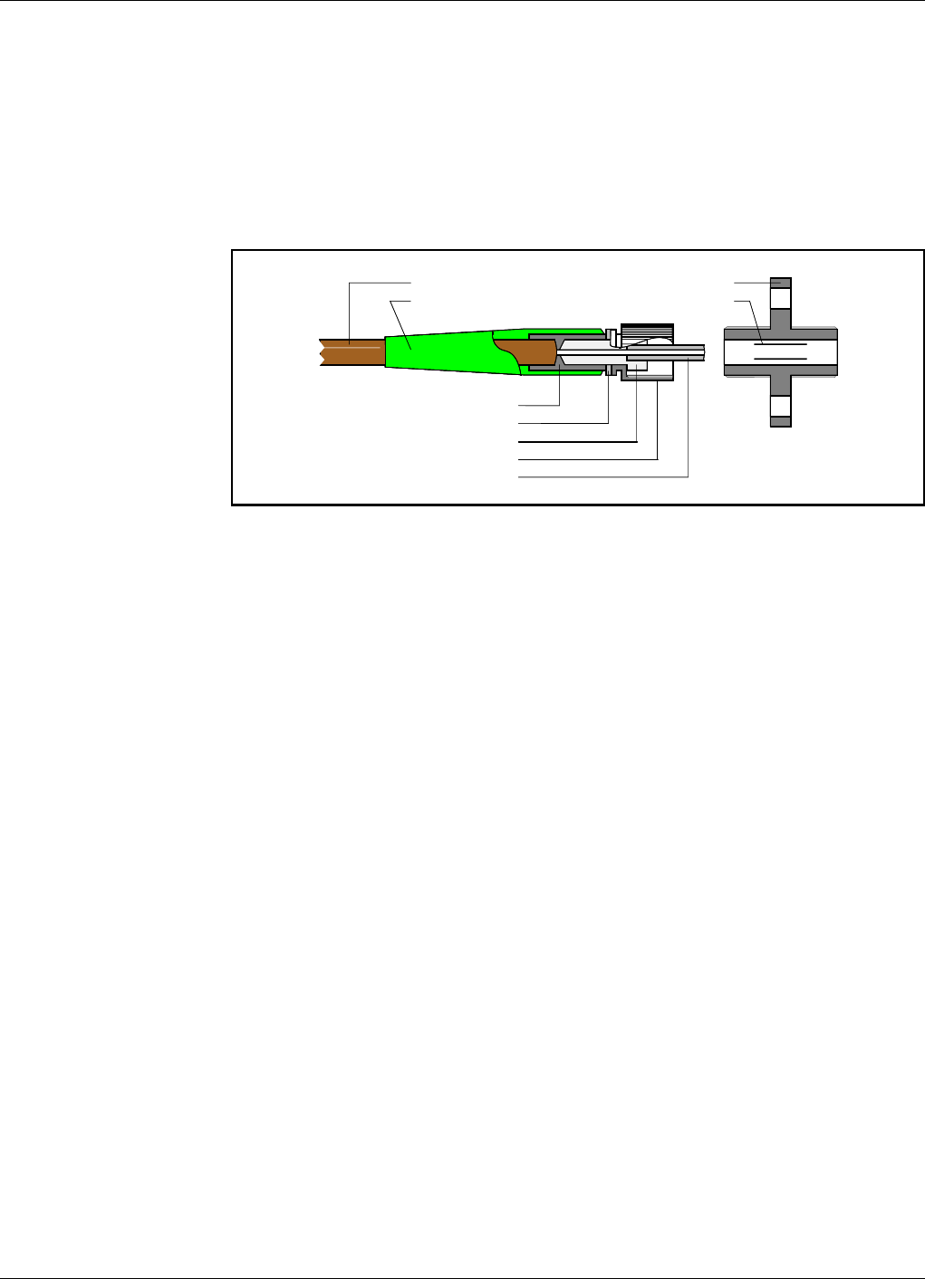
Powerwave Fiber Optics
VM100 56/EN – User’s Manual Rev. P1A9-Draft 2004-11 7 - 9
Fiber Optic Connectors
There are a number of fiber optic connector types that have different charactersistics,
advantages, and disadvantages. There are, however, three basic connector parts that all
of these types have in common. These are the connector body, the ferrule, and the
coupling device.
Figure 7-10 illustrates a typical fiber connector in which these three parts, and other
main parts, are pointed out.
Figure 7-10. Typical fiber optic connector
Connector body
The connector body, or connector housing, holds the ferrule in a center line of the
connector. The connector body is generally made of metal or plastic and it can
consist of one or many pieces.
Ferrule
The ferrule holds and align the fiber. The ferrule is, when inserted in the coupler,
guided by an alignment sleeve to the right position to meet the connected fiber with
a minimum of misalignment.
The ferrule end and the fiber end are aligned in the same plane. The fiber face is
polished in this plane to minimize power loss. Hackles, lips, fractures, and dirt at
this face cause scattering and thus power loss.
Ferrules are typically made of metal or ceramic, but can also be made of plastic.
Coupling device
A coupling device, such as an alignment sleeve, is used instead of male and female
connectors common to electric devices.
Fiber optic transmitters and receivers, as well as splitters and WDMs, often have the
coupling devices built-in and can thus be connected with applicable cable
connectors.
Connector insertion loss
All connectors have an insertion loss of 0.5dB.
Fiber cable
Bend relief boot
Coupling device
Alignment sleeve
Crimp ferrule
Retaining ring
Connector body
Knurled coupling nut
Ferrule

Fiber Optics Powerwave
7 - 10 Rev. P1A9-Draft 2004-11 VM100 56/EN – User’s Manual
Connector Types
The most common fiber optic connectors for Powerwave repeaters are briefly described
below.
DIN
These are keyed, spring-loaded connectors with floating sleeves in the couplers. They
have threaded coupling nuts.
DIN/APC, see APC connectors below.
FC
The ferrule in a FC connector has face contact (FC) with the joined connector. This type
has a threaded coupling nut.
FC/APC, see APC connectors below.
FC/PC, see PC connectors below.
SC
The subscription channel (SC) connector is a push-pull connector that gives a click
sound when pushed in or pulled out. The ferrule in this connector is decoupled from the
cable and the connector body, which means that the ferrule is not affected by cable
touches.
SC/APC, see APC connectors below.
SC/PC, see PC connectors below.
ST
The straight tip (ST) connector has a spring-loaded bayonet coupling that makes the
ferrule not rotate during connection, which means that the insertion loss is consistent.
APC connectors
All APC connector types are angle polished connectors (APC). In such a connector, the
ferrule with the fiber end face is not at straight angle to the fiber center axis (typical
deviation for the connectors used is 8° but a deviation of 5° to 15° is common). These
connectors have a low backreflection.
PC connectors
All PC connector types have the ferrule with the fiber end face polished in a certain
curve for physical contact (PC). These connectors have a low backreflection.
E2000 connectors
The E2000 connector has a ceramic ferrule and a moulded plastic body that includes a
push-pull latch mechanism. This connector has a spring loaded protective cap over the
ferrule that protects the fiber end face from dirt and dust and also protects from laser
emission.

Powerwave Fiber Optics
VM100 56/EN – User’s Manual Rev. P1A9-Draft 2004-11 7 - 11
Handling Connectors
Always have in mind that the fiber area in a fiber optic connector is very small. The
diameter of the fiber in a single-mode connector is only 9µm. Compared to a human hair,
which is between 50 and 75µm, the fiber diameter is only about a seventh of that
diameter.
This means that a very small particle on the fiber end face causes trouble. A dust particle,
1µm in size, can suspend indefinitely in the air. On the fiber end face in a connector, this
particle can cause a loss of 1dB. A 9µm dust particle can completely put an end to the
signal.
Dust particles are usually 20µm or larger in diameter.
This makes it necessary to cover and clean optical connectors as described below.
Covering
An optical connector that is not in use must always be covered.
If, for example, an unprotected connector is dropped, the fiber end face may be damaged
when it reaches the floor.
A protection boot is usually provided by the connector manufacturer. It should protect
the entire connector, but at least the ferrule.
Cleaning
Always clean optical connectors immediately before inserting them into the coupling
ports. But, wait until the cleaning liquid has get absolutely dry.
Use the following cleaning equipment:
•Fiber cleaning cloths.
•Denaturated alcohol.
•Canned dry air.
•30X microscope (for cleaning verification).
Clean as follows:
1. Ensure the laser transmitter is off.
2. Clean by using a cleaning device.
Or:
– Saturate the fiber cleaning cloth with alcohol and clean the entire connector,
especially the ferrule with the fiber end face. The cloth must not be dry.
– Verify the cleaning result by using the microscope.
– Canned air can be used to remove particles from the coupling port. Do not use
cleaning liquid in the coupling port.
– Never touch the fiber end face.

Fiber Optics Powerwave
7 - 12 Rev. P1A9-Draft 2004-11 VM100 56/EN – User’s Manual

Powerwave Fiber Optics
VM100 56/EN – User’s Manual Rev. P1A9-Draft 2004-11 8 - 1
8. Troubleshooting
This troubleshooting guide is applicable to a BMU connected to a BTS. The BMU is
also the master unit in a fiber optic network built-up with FON units, one in the BMU
and one in each of the connected repeaters.
This guide assumes that no gateway is available in the repeater network, and that alarms
are indicated via an alarm relay in the BMU.
At the BMU site
1. Inspect the BTS and BMU sites.
If a general inspection of the BTS site does not explain the cause of the error, then
open the cabinet of the BMU.
2. Check the power in the BMU.
This includes the BMU power supply and the fuse in the distribution panel.
If a replacement of the PSU does not solve the problem, then check the power
distribution cable from the PSU to the FON unit.
3. Check the red FAULT and the green FLI/F2F indicators.
If neither the red FAULT indicator in the BMU or the green FLI/F2F indicator are
blinking, then the FON unit is not communicating properly with any of the remote
repeaters.
If there are more than one repeater in the repeater network, then the problem is
most likely related to the fiber at the BMU site, or the fiber cable between the
BMU and the repeaters.
4. Measure the received uplink 1310nm optical power from the repeater at the patch
cables in the BMU.
If the measured optical power is higher than –10dBm, then proceed with step 5.
If there is no optical power, then check the signal power at the patch panel.
5. Measure the optical uplink power at the RX port of the current FON unit.
If the signal power is OK, then proceed with step 6.
If there is no power in the RX port, then clean the connectors and measure again.
If there is still no power in the RX port, then replace the FOU unit with the passive
devices (keep the FON board). The problem is very likely related to a
misfunctioning splitter or WDM.
6. Measure the optical downlink transmitting power at the TX port of the same FON
unit.
If the signal power is not OK, then replace the FON board.

Fiber Optics Powerwave
8 - 2 Rev. P1A9-Draft 2004-11 VM100 56/EN – User’s Manual
At the repeater site
7. Repeat from step 2 to step 6 but now in the repeater.
8. If there are further repeaters in the network, then measure the optical output power
to the next repeater.
If there is no power, then the problem most likely refers to the optic splitter.
Replace the FOU unit with the passive devices (keep the FON board).
A misfunctioning splitter can also be the cause of lost repeaters between the BMU
and the current site.
9. As soon as the optical system works, log on to the repeater and read the RF
information in the event log.
If the error is caused by the RF system, then copy all settings from the current RF
unit into a new RF unit and replace the RF unit.
The quickest way to determine if the RF level is OK in the repeater is to log on to
the repeater and check the RSSI values for the BCCH channel. This value should
be between –40dBm and –50dBm.
If the RSSI value is not between these values and the FON unit works properly,
then measure the RF level from the FOU to the repeater DC coupler using a
sitemaster, spectrum analyser, or similar.
If the loss is 20dB or more, then the LNA amplifier or the DPX filter is
misfunctioning.

Powerwave Fiber Optics Index
VM100 56/EN – User’s Manual Rev. P1A9-Draft 2004-11 I - 1
Index
A
Abbreviations ...................................................................................................... v
APC connectors ............................................................................................... 7-10
B
BATT, green LED ............................................................................................. 3-7
Beamsplitter ..................................................................................................... 7-2
BOOT, red LED ................................................................................................ 3-7
C
Capillary splicing .............................................................................................. 7-7
CHARGE, yellow LED ....................................................................................... 3-7
Commissioning ................................................................................................. 6-1
D
DATA, blue LED .............................................................................................. 3-7
DIN connectors ............................................................................................... 7-10
E
E2000 connectors ............................................................................................ 7-10
ESD ................................................................................................................ 1-6
F
FAULT, red LED .............................................................................................. 3-7
FC connectors ................................................................................................. 7-10
Fiber-Optic Node ............................................................................................... 3-1
FLI ................................................................................................................. 5-2
FLI, green LED ................................................................................................. 3-6
F-link .............................................................................................................. 5-2
F-net ............................................................................................................... 5-2
F-net characteristics ........................................................................................... 5-4
FON ................................................................................................................ 3-1
FON operational control ................................................................................... 3-11
FON unit .......................................................................................................... 5-6
Fusion splice ..................................................................................................... 7-7
Fusion splicer ................................................................................................... 7-7
G
Graphic symbol, optical splitter ............................................................................ 7-3
Graphic symbol, WDM ....................................................................................... 7-5
I
Introduction ...................................................................................................... 2-1
IP ................................................................................................................... 5-2
IP network ........................................................................................................ 5-1
IP network requirements ..................................................................................... 5-3
IP terminology .................................................................................................. 5-2

Index Fiber Optics Powerwave
I - 2 Rev. P1A9-Draft 2004-11 VM100 56/EN – User’s Manual
L
Link ................................................................................................................ 5-2
M
Mechanical splice ............................................................................................... 7-7
N
Net and link ...................................................................................................... 5-2
Node units ........................................................................................................ 5-5
O
OPER, green LED .............................................................................................. 3-7
Operational control, FON .................................................................................. 3-11
Optical splitter ................................................................................................... 7-2
Optical splitter graphic symbol ............................................................................. 7-3
OSP ................................................................................................................. 7-2
P
PC connectors ................................................................................................. 7-10
Port section
LOCAL O&M .............................................................................................. 3-9
Ports
P101 RF input ............................................................................................... 3-8
P102 RF output ............................................................................................. 3-8
P103 RF low power output .............................................................................. 3-8
P104 Debug ................................................................................................. 3-9
P105 Front LED indicators .............................................................................. 3-9
P106 PC ...................................................................................................... 3-9
P108 Power .................................................................................................. 3-9
P109 Alarm .................................................................................................. 3-9
P110 W-link jumper ..................................................................................... 3-10
P111 WLI .................................................................................................. 3-10
P112 WLI .................................................................................................. 3-10
P113 Batteries ............................................................................................ 3-10
P114 Backup power output ............................................................................ 3-10
P115 Future port ......................................................................................... 3-10
P116 Power .................................................................................................. 3-9
P130 RCC .................................................................................................. 3-10
RX ............................................................................................................. 3-8
TX .............................................................................................................. 3-8
POWER, yellow LED ......................................................................................... 3-7
Q
Questionnaire ................................................................................................... Q-1
R
R2R ....................................................................................................... 3-4, 5-2
R2R net ............................................................................................................ 5-2
R2R terminology ............................................................................................... 5-2
S
Safety .............................................................................................................. 1-1
beryllium oxide ............................................................................................. 1-1
electric shock ................................................................................................ 1-1
hydrogen fluoride .......................................................................................... 1-1
laser transmitter ............................................................................................ 1-2

Powerwave Fiber Optics Index
VM100 56/EN – User’s Manual Rev. P1A9-Draft 2004-11 I - 3
lithium battery .............................................................................................. 1-1
polytetrafluoro ethylene ................................................................................. 1-1
PTFE .......................................................................................................... 1-1
SC connectors ................................................................................................. 7-10
Single-Mode Fiber ............................................................................................. 8-1
SLW ...................................................................................................... 3-4, 5-2
ST connectors ................................................................................................. 7-10
Static electricity ................................................................................................. 1-6
T
Tee coupler ...................................................................................................... 7-2
Terminology ..................................................................................................... 5-2
W
Wavelength Division Multiplexer ......................................................................... 7-4
WDM graphic symbol ........................................................................................ 7-5
WLI ....................................................................................................... 3-4, 5-2
WLI, green LED ................................................................................................ 3-7
W-link ............................................................................................................. 5-2
W-net ..................................................................................................... 3-4, 5-2

Index Fiber Optics Powerwave
I - 4 Rev. P1A9-Draft 2004-11 VM100 56/EN – User’s Manual

Powerwave Fiber Optics Questionnaire
VM100 56/EN – User’s Manual Rev. P1A9-Draft 2004-11 Q - 1
Questionnaire
The aim of this manual is to guide you when installing and operating the Powerwave
repeaters, and to answer questions that may turn up. To ensure that we provide
appropriate information for these purposes, we would appreciate your views and
suggestions on how to improve the manual in this direction. Please, fill out the following
questionnaire and send it to us.
1Have you read entire sections or do you use the manual to look up specific information
when needed?
Read entire sections Look up specific information
Comments: ___________________________________________________________
_____________________________________________________________________
_____________________________________________________________________
2Do you think the information is easy to find and understand?
Yes No
Comments: ___________________________________________________________
_____________________________________________________________________
_____________________________________________________________________
3Do you find any function of the Powerwave repeater hard to understand, a function
which should be subjected to more detailed description?
Yes No
If yes, which one: ______________________________________________________
_____________________________________________________________________
_____________________________________________________________________
4Do you have any suggestions on how we can improve this manual?
_____________________________________________________________________
_____________________________________________________________________
_____________________________________________________________________
Title (Mr/Ms/Other): ________________________________ Initial: _________________________________________________________
Surname: _________________________________________ Job title: _______________________________________________________
Company: _________________________________________ Address: _______________________________________________________
City: _____________________________________________ Country: _______________________ Phone: _________________________
Thanks for your kind help. It's very valuable to us.

Questionnaire Fiber Optics Powerwave
Q - 2 Rev. P1A9-Draft 2004-11 VM100 56/EN – User’s Manual
Powerwave Technologies Sweden AB
Customer Care
SE-187 80 Täby
Sweden
If you prefer to send by mail, fold here and tape.
No envelope required.
If you prefer to send by fax, use this number: +46 8 540 824 85
POSTAGE
STAMP