Pro Nets Technology WA41R Wireless ADSL 2+ ROUTER User Manual
Pro-Nets Technology Corporation Wireless ADSL 2+ ROUTER
Contents
- 1. user manual 1
- 2. user manual 2
- 3. user manual 3
- 4. user manual 4
user manual 2
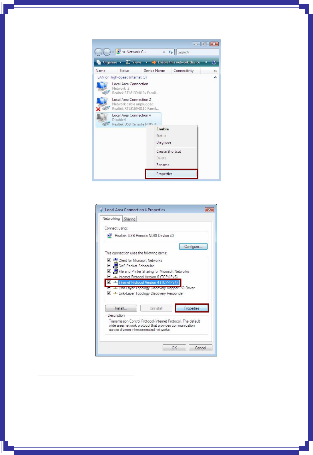
19
Step 5: Select Internet Protocol Version 4 (TCP/IPv4) then click Properties:
Configure IP address Automatically:
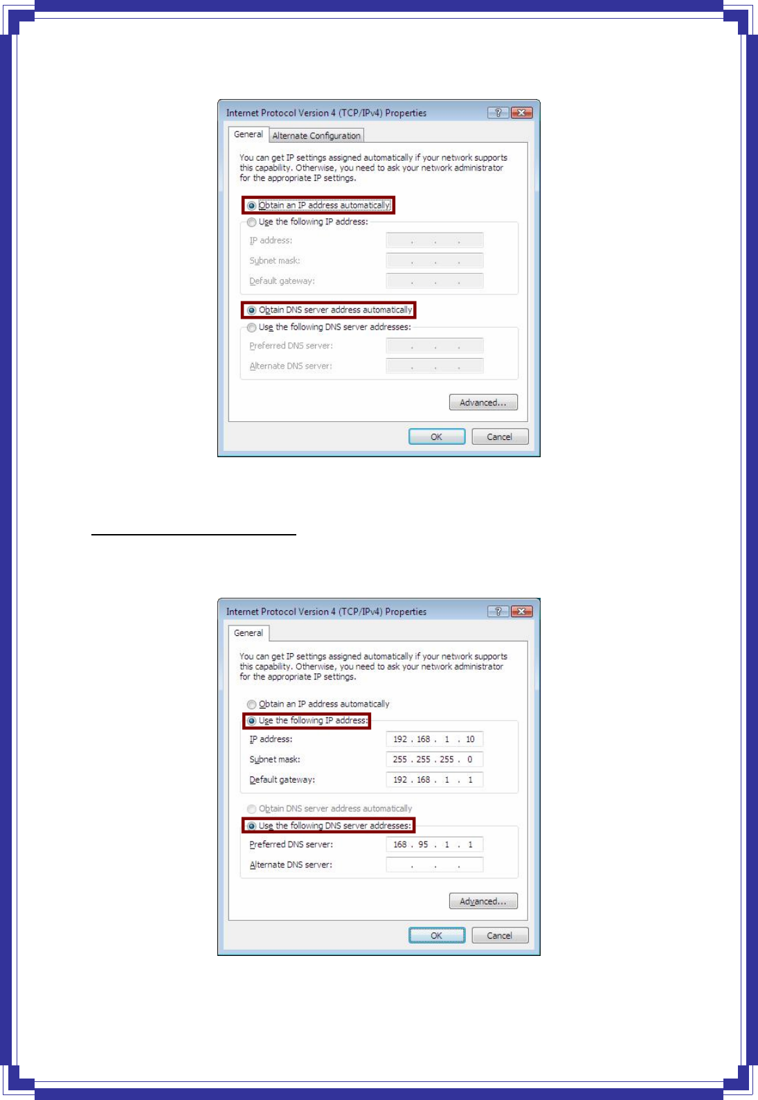
Step 6: Select Obtain an IP address automatically and Obtain DNS server address
automatically. Click OK to finish the configuration.
20
Configure IP Address Manually:
Step 7: Select Use the following IP address and Use the following DNS server
addresses.
IP address: Fill in IP address 192.168.1.x (x is a number between 2 to 254).
21
Subnet mask: Default value is 255.255.255.0.
Default gateway: Default value is 192.168.1.1.
Preferred DNS server: Fill in preferred DNS server IP address.
Alternate DNS server: Fill in alternate DNS server IP address.
You can use ping command under DOS prompt to check if you have setup TCP/IP protocol
correctly and if your computer has successfully connected to this router.
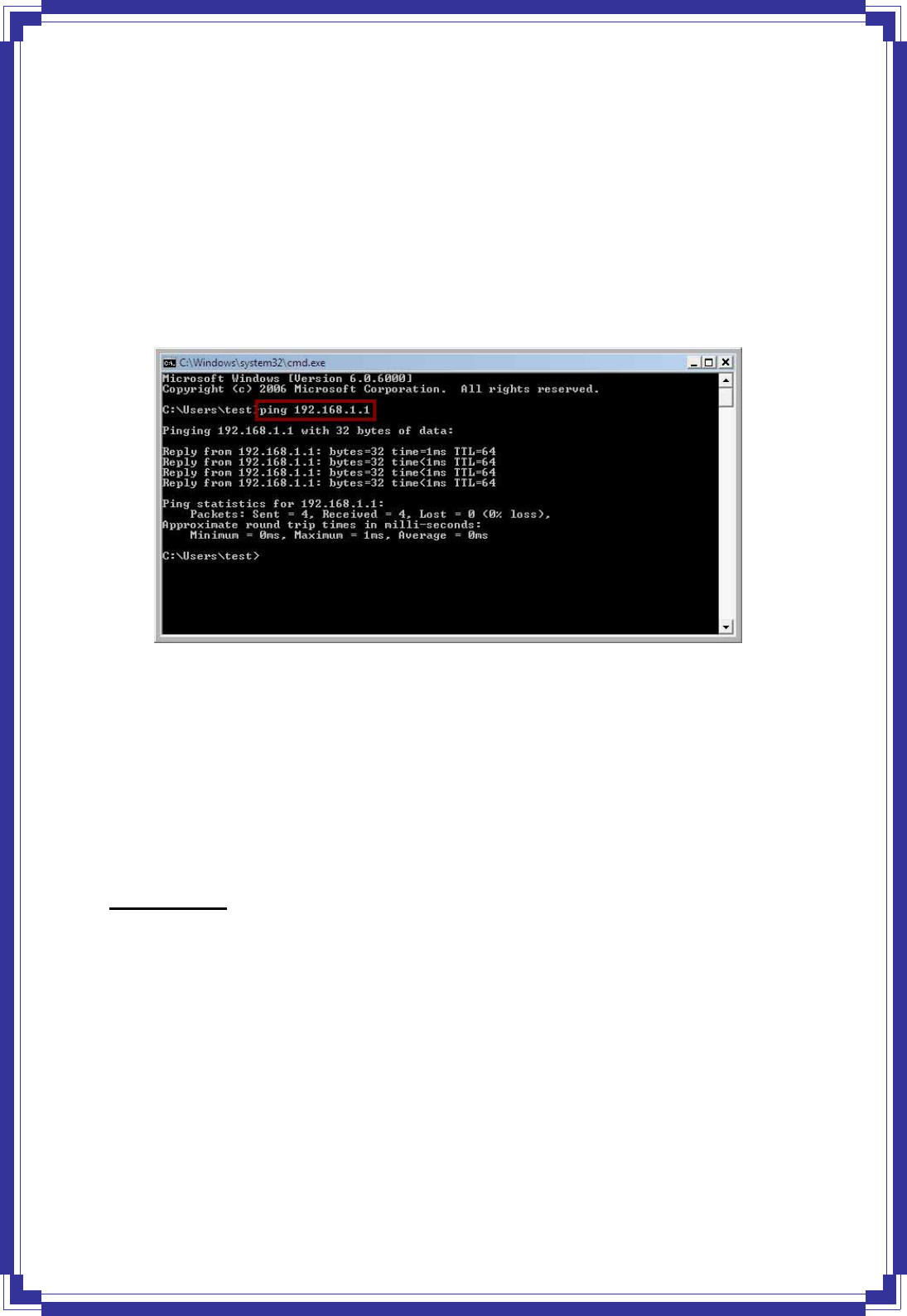
1) Type ping 192.168.1.1 under DOS prompt and the following messages will appear:
If the
communication link between your computer and router is not setup correctly, after you type
ping 192.168.1.1 under DOS prompt following messages will appear:
Pinging 192.168.1.1 with 32 bytes of data:
Request timed out.
Request timed out.
Request timed out.
This failure might be caused by cable issue or something wrong in configuration procedure.
For Windows 7
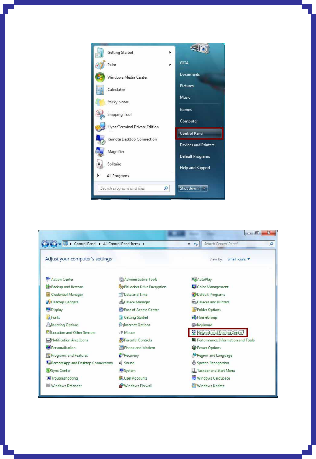
Step 1: Click Start then select Control Panel.
22
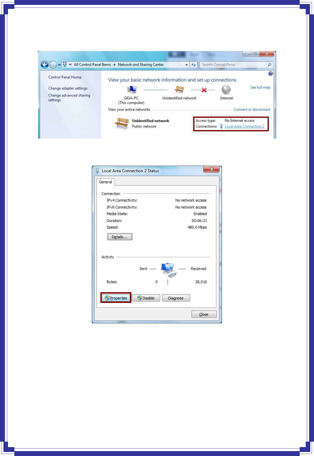
Step 2: Double-click Network and Sharing Center icon.
23
Step 3: Select “Local Area Connection #”. (local network your ADSL hooked up with)
Step 4: Select Properties:
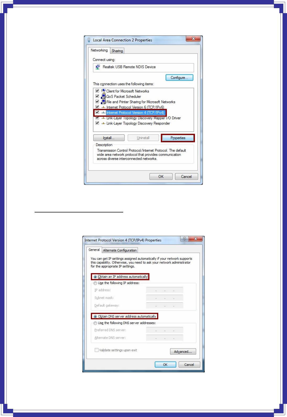
Step 5: Select Internet Protocol Version 4 (TCP/IPv4) then click Properties:
24
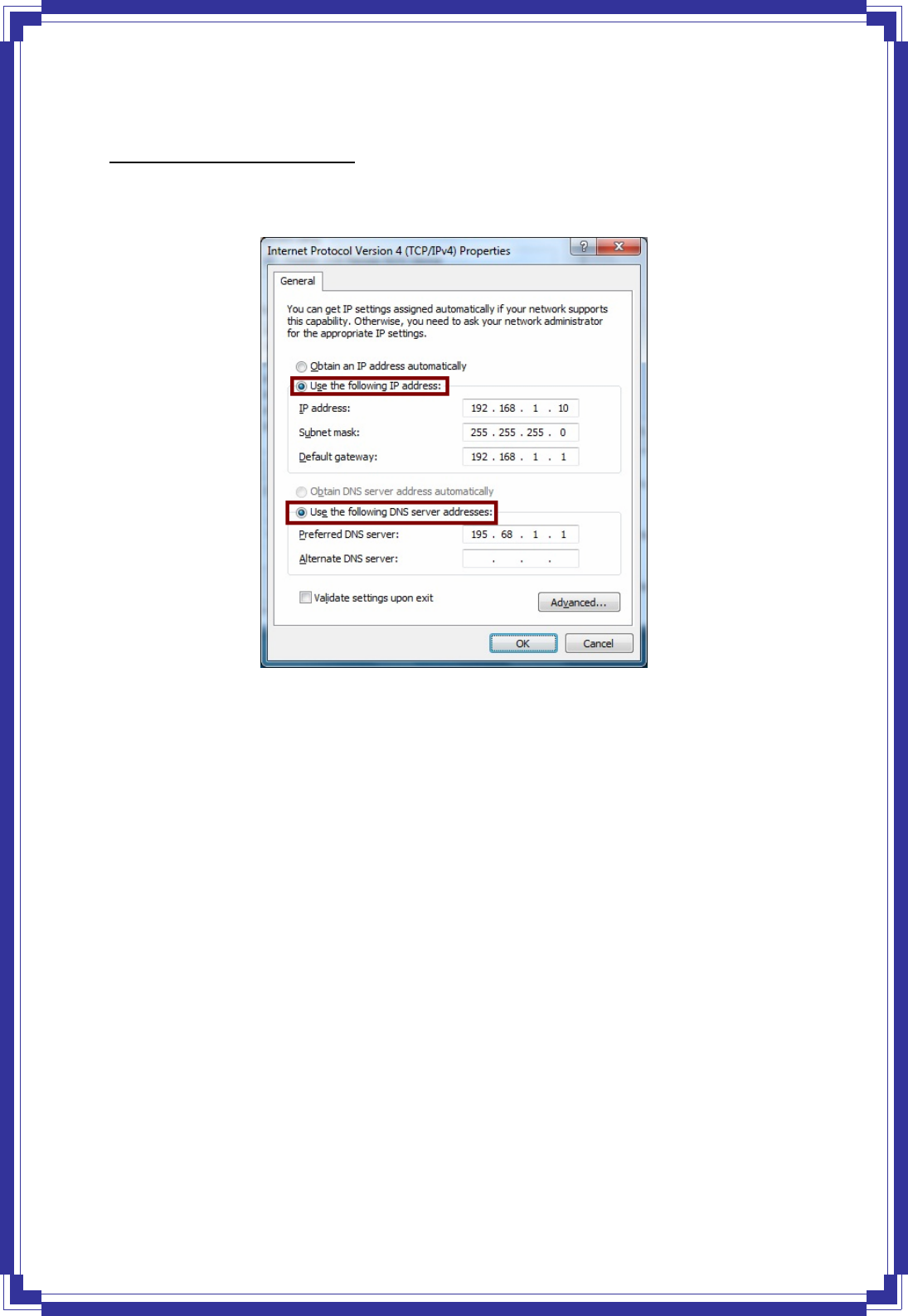
Configure IP address Automatically:
Step 6: Select Obtain an IP address automatically and Obtain DNS server address
automatically. Click OK to finish the configuration.
25
Configure IP Address Manually:
Step 7: Select Use the following IP address and Use the following DNS server
addresses.
IP address: Fill in IP address 192.168.1.x (x is a number between 2 to 254).
Subnet mask: Default value is 255.255.255.0.
Default gateway: Default value is 192.168.1.1.
Preferred DNS server: Fill in preferred DNS server IP address.
Alternate DNS server: Fill in alternate DNS server IP address.
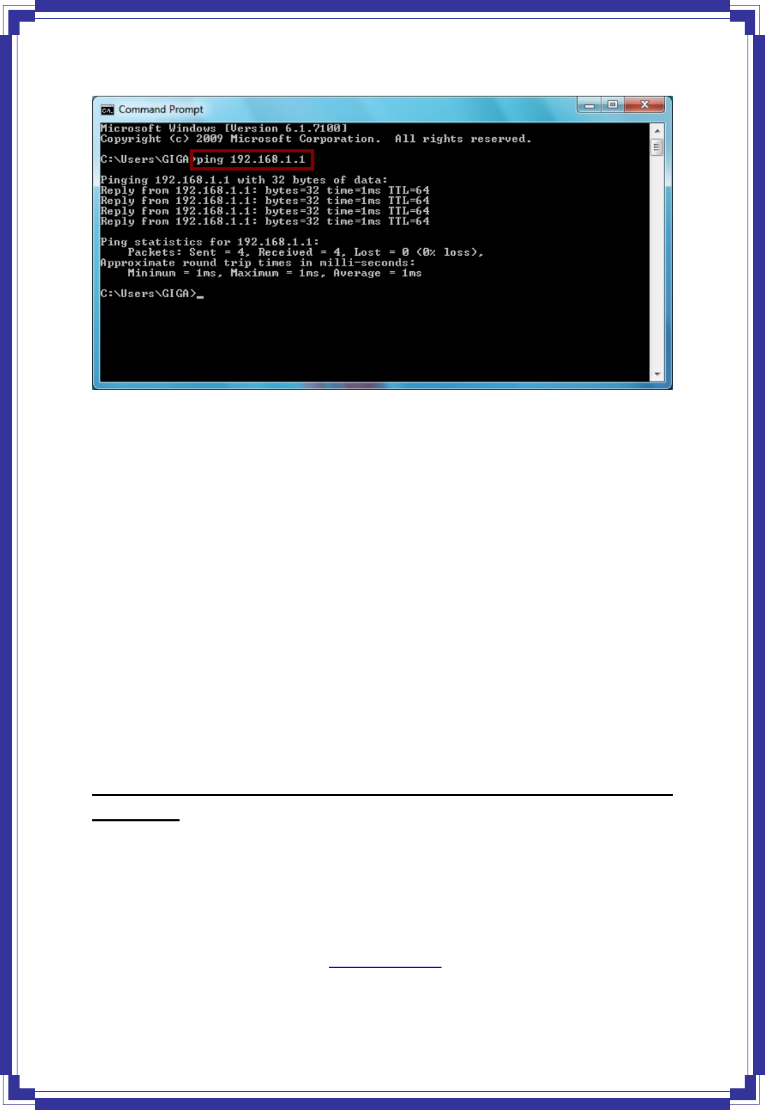
You can use ping command under DOS prompt to check if you have setup TCP/IP protocol
correctly and if your computer has successfully connected to this router.
1) Type ping 192.168.1.1 under DOS prompt and the following messages will appear:
26
If the communication link between your computer and router is not setup correctly, after you
type ping 192.168.1.1 under DOS prompt following messages will appear:
Pinging 192.168.1.1 with 32 bytes of data:
Request timed out.
Request timed out.
Request timed out.
This failure might be caused by cable issue or something wrong in configuration procedure.
4. Configure Wireless LAN ADSL2+ Router via HTML
Interface
Wireless LAN ADSL2+ Router supports a Web-based (HTML) GUI to allow users to configure
Router setting via Web browser.
4.1 Login
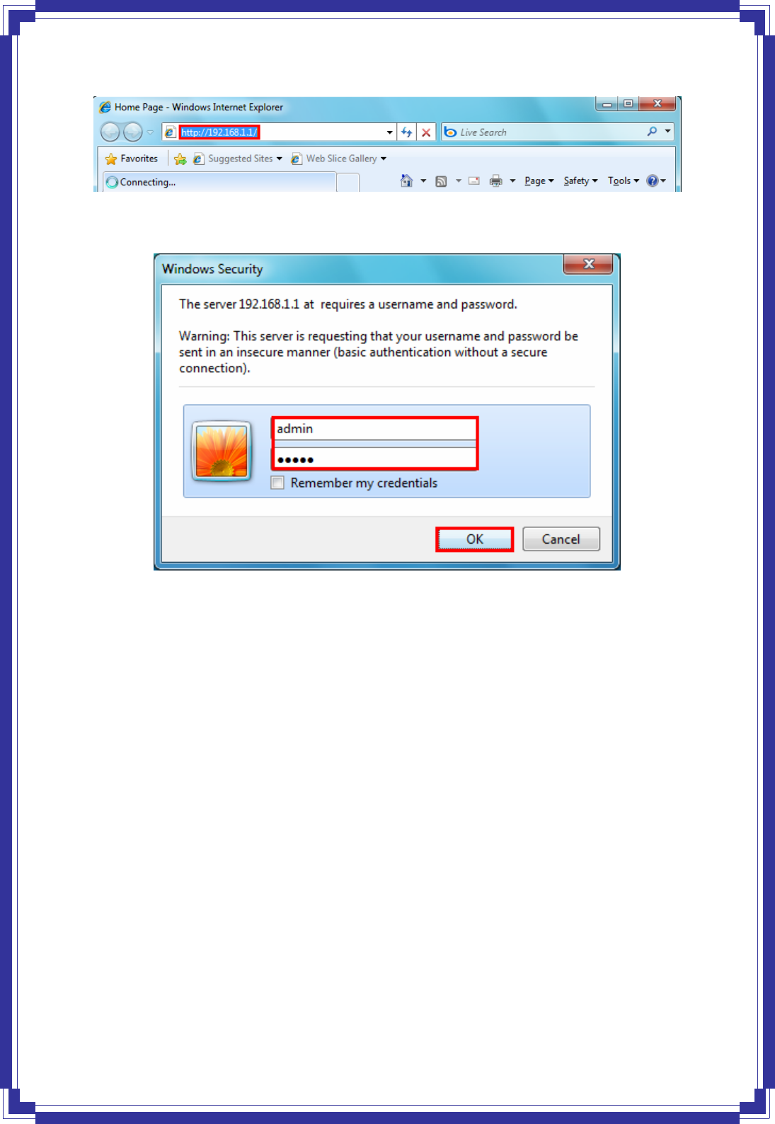
1) Launch the Web browser.
2) Enter the default IP address http://192.168.1.1
27
3) Entry of the username and password will be displayed. Enter the default login
User Name and Password as admin and admin.
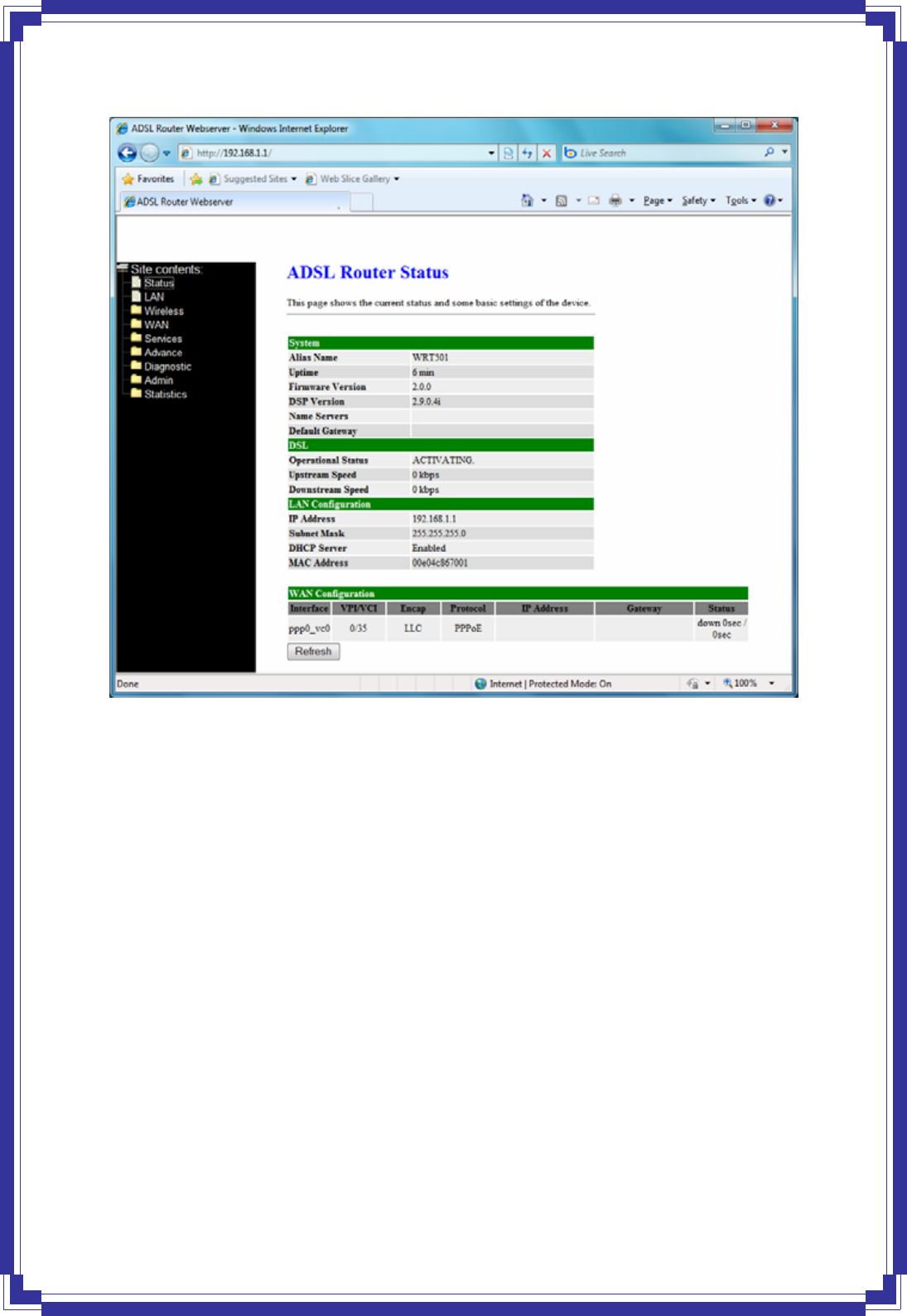
The main webpage will be displayed as below:
28
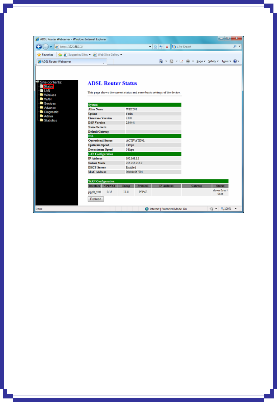
4.2 Status
This page displays the ADSL router’s current status and settings. Click “Refresh” button to
update the status.
29
4.3 LAN
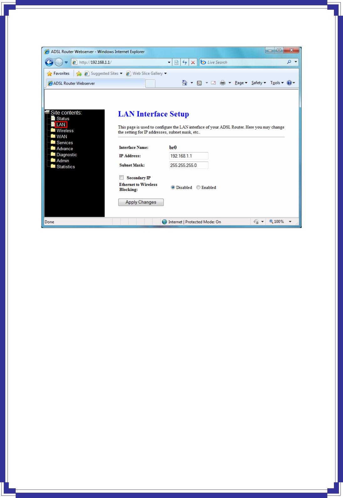
This page shows the current setting or LAN interface. You can set IP address and subnet
mask for LAN interface in this page.
30
IP Address -- The IP Address which your LAN hosts use to identify the device’s LAN port.
Subnet Mask -- LAN Subnet mask.
Apply Change -- Click to save the setting to the configuration. New parameters will take effect
after save into flash memory and reboot the system.
4.4 Wireless
4.4.1 Basic Settings
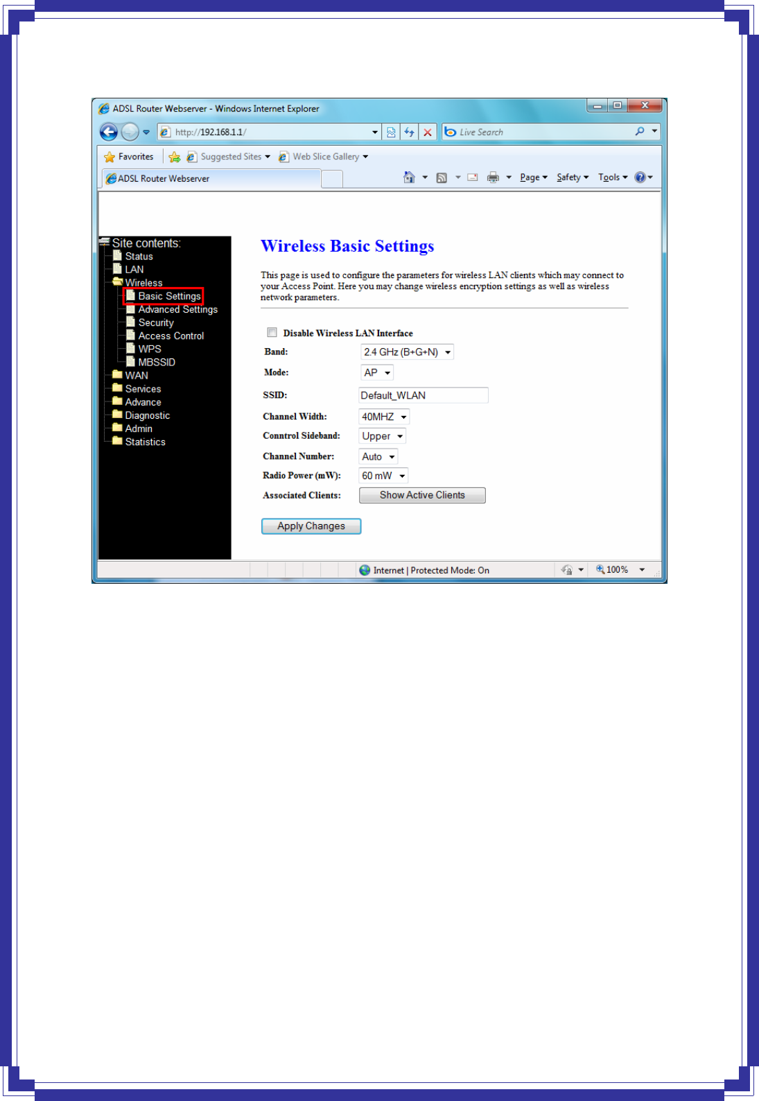
This page is used to configure the parameters for wireless LAN clients who may connect to
your Access Point. Here you may change wireless encryption settings as well as wireless
network parameters.
31
Band: This is the range of frequencies the gateway will use to communicate with your wireless
devices. As you’re looking for products in stores or on the Internet, you might notice that you
can choose equipment that supports six different wireless networking technologies: 2.4
GHz(B), 2.4 GHz(G), 2.4 GHz(B+G), 2.4 GHz(N), 2.4 GHz(G+N), and 2.4 GHz(B+G+N).
Mode: Default set to AP mode.
SSID: Specify the network name. Each Wireless LAN network uses a unique Network Name to
identify the network. This name is called the Service Set Identifier (SSID). When you set up
your wireless adapter, you specify the SSID. If you want to connect to an existing network, you
must use the make up your own name and use it on each computer. The name can be up to 20
characters long and contain letters and numbers.
Channel Width: There have 2 options – 20MHZ and 40 MHZ
Control Sideband: Specify if the extension channel should be in the Upper or Lower
sideband.
Channel Number: Sets the channel on which the gateway operates.
Radio Power (mW): A milliwatt (mW) is also a unit of power. To put it simply, a milliwatt is
1/1,000 of a watt. The reason you need to be concerned with milliwatts is because most of the
32
802.11 equipment that you will be using transmits at power levels between 1 and 100 mW
Associated Clients: This table shows MAC address, transmission, reception packet counters
and encrypted status for each associated wireless clients.
4.4.2 Advanced Settings
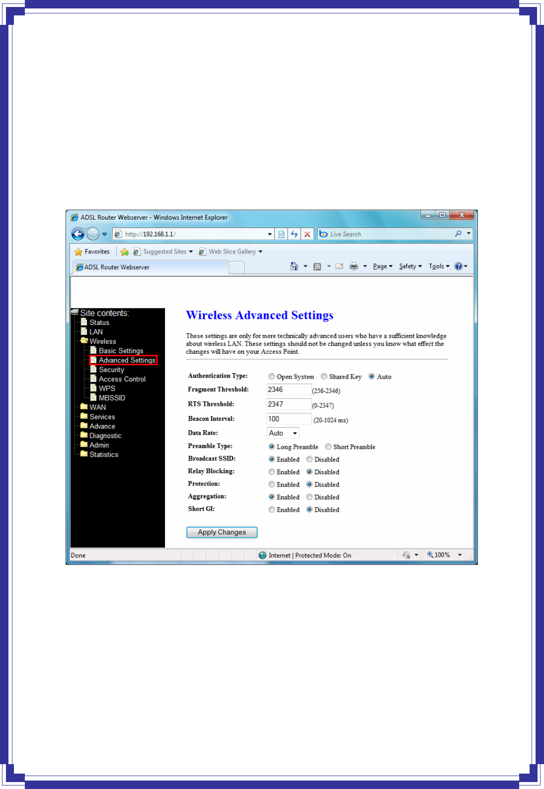
These settings are only for more technically advanced users who have a sufficient knowledge
about wireless LAN. These settings should not be changed unless you know what effect the
change will have on your Access Point.
Authentication Type: There has 3 types – Open System, Shared Key, and Auto
Fragment Threshold: Fragmentation Threshold sets the frame size of incoming messages
(ranging from 256 to 2346 bytes) used as fragmentation boundary. If the frame size is too big,
the heavy interference affects transmission reliability. If the frame size is too small, it
decreases transmission efficiency. Default setting is 2346.
RTS Threshold: Lower the signal RTS (Request To Send) to promote the transmission
efficiency in condition of noisy environment or too many clients. Default setting is 2347.
Beacon Interval: Beacon Interval means the period of time between one beacon and the next
33
one. The default value is 100 (the unit is millisecond, or 1/1000 second). Lower the Beacon
Interval to improve transmission performance in unstable environment or for roaming clients,
but it will be power consuming.
Data Rate: Set the wireless data transfer rate to a certain value. Since most of wireless
devices will negotiate with each other and pick a proper data transfer rate automatically, it’s
not necessary to change this value unless you know what will happen after change the value.
[Auto] is recommended to maximize performance.
Preamble type: Preamble is the first sub field of PPDU, which is the appropriate frame format
for transmission to PHY (Physical layer). There are two options, Short Preamble and Long
Preamble.
Short GI: Using a short (400ns) guard interval can increase throughput. However, it can also
increase error rate in some installations, due to increased sensitivity to radio-frequency
reflections
4.4.3 Security
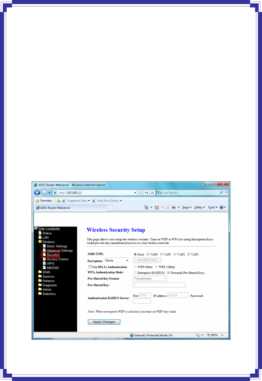
This page allows you setup the wireless security. Turn on WEP or WPA by using Encryption
Keys could prevent any unauthorized access to your wireless network.
34
Encryption: There have 4 encryption options – WEP, WAP (TKIP), WPA2(AES), and WPA2
Mixed.
WPA authentication mode: WPA operates in either WPA-PSK mode (Pre-Shared Key or
WPA-Personal) or WPA-802.1x mode (RADIUS or WPA-Enterprise). In the Personal mode, a
pre-shared key or passphrase is used for authentication. In the Enterprise mode, which is
more difficult to configure, the 802.1 x RADIUS servers and an Extensible Authentication
Protocol (EAP) are used for authentication.
Pre-Shared Key Format: select Passphrase mode or Hex mode for the Pre-Shared Key.
Pre-Shared Key: Enter the Pre-Shared via using the Passphrase mode or Hex mode.
Authentication RADIUS server: fill the port, IP address and the password of the RADIUS
server.
4.4.4 Access Control
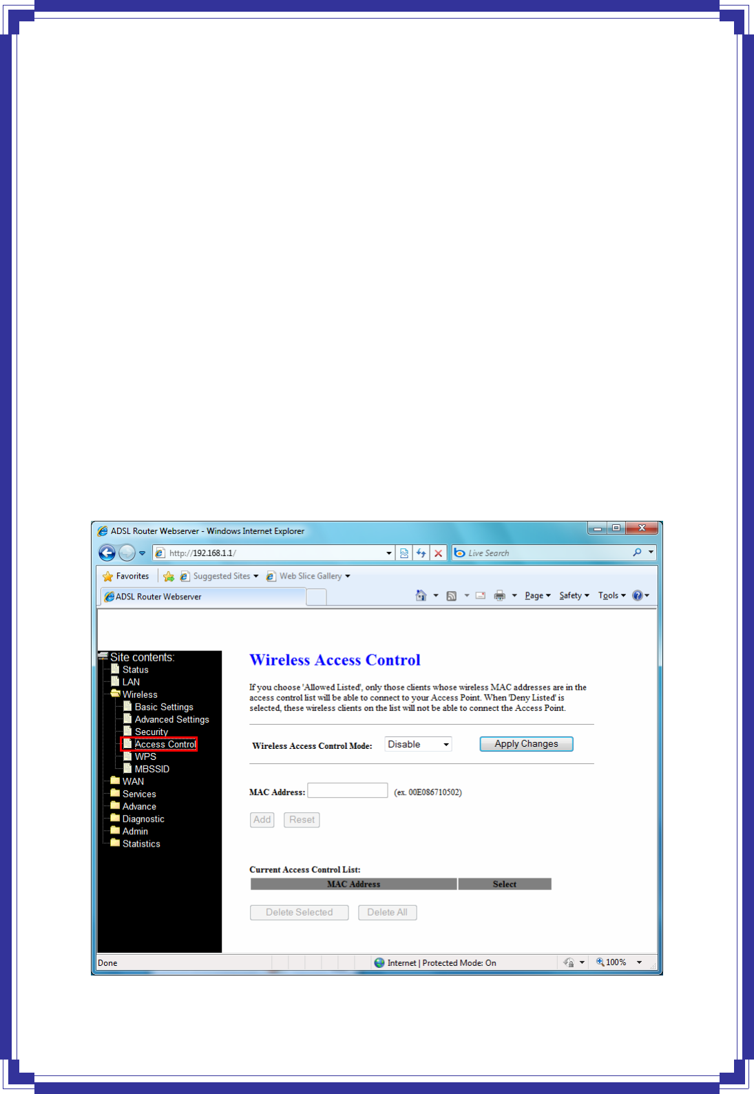
If you know choose “Allowed Listed” from Wireless Access Control mode, only chose clients
whose wireless MAC address are in the access control list will be able to connect to your
Access Point. When “Deny Listed” is selected, these wireless clients on the list will not be
able to connect the AP.
35
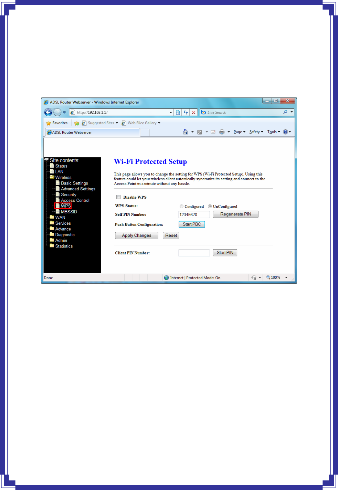
4.4.5 WPS
This page allows you to change the setting for WPS (Wi-Fi Protected Setup). Using this
feature could let your wireless client automatically synchronize its setting and connect to the
Access Point in a minute without any hassle.
In PIN method (PIN-Personal Identification Number), When your 11n router acts as a
Registrar, your must enter “Self-PIN Number” on WPS config section, this Enrollee PIN code
should be provided by the Enrollee. If your 11n router acts as a Enrollee, in WPS config
section, the “Regenerate PIN” will automatically generate for you. The purpose of PIN code is
to provide the security key to Registrar (AP/Server). Therefore, WPS (Wi-Fi Protected Setup)
can be established completely.
In PBC Method (PBC-Push Button Communication), while the AP router acts as Registrar or
Enrollee, and click “Start PBC” button, the WPS (Wi-Fi Protected Setup) will establish the
connection automatically.
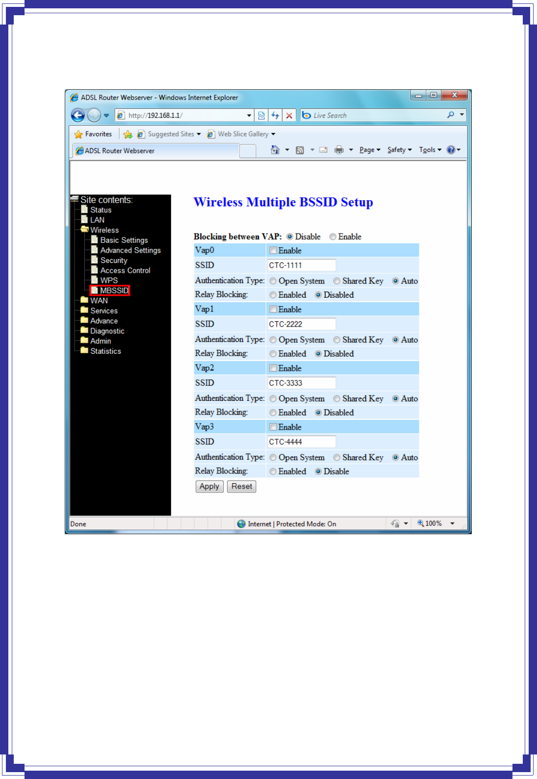
4.4.6 MBSSID
This page allows you to setup wireless multiple BSSID configuration. The Base Service Set
Identifier (BSSID) is typically the MAC address if the radio. This Wireless LAN ADSL2+ Router
also supports multiple BSSIDs (MBSSID) on a single AP.
36
4.5 WAN
There are three sub-menus for WAN configuration: Channel Config, ATM Settings, and
ADSL Settings.
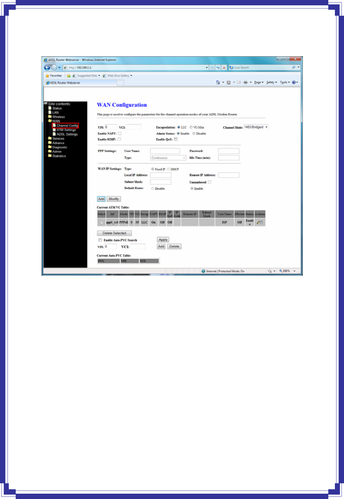
4.5.1 Channel Configuration
ADSL router comes with 8 ATM Permanent Virtual Channels (PVCs) at the most. There are
mainly three operations for each of the PVC channels: add, delete, and modify. And there are
several channel modes to be selected for each PVC channel. For each of the channel modes,
37
the setting is quite different accordingly.
Add -- Click Add to complete the channel setup and add this PVC channel into configuration.
Modify -- Select an existing PVC channel by clicking the radio button at the Select column of
the Current ATM VC Table before we can modify the PVC channel. After selecting a PVC
channel, we can modify the channel configuration at this page. Click Modify to complete the
channel modification and apply to the configuration.
Delete -- Select an existing PVC channel to be deleted by clicking the radio button at the
Select column of the Current ATM VC Table. Click Delete to delete this PVC channel from
configuration.
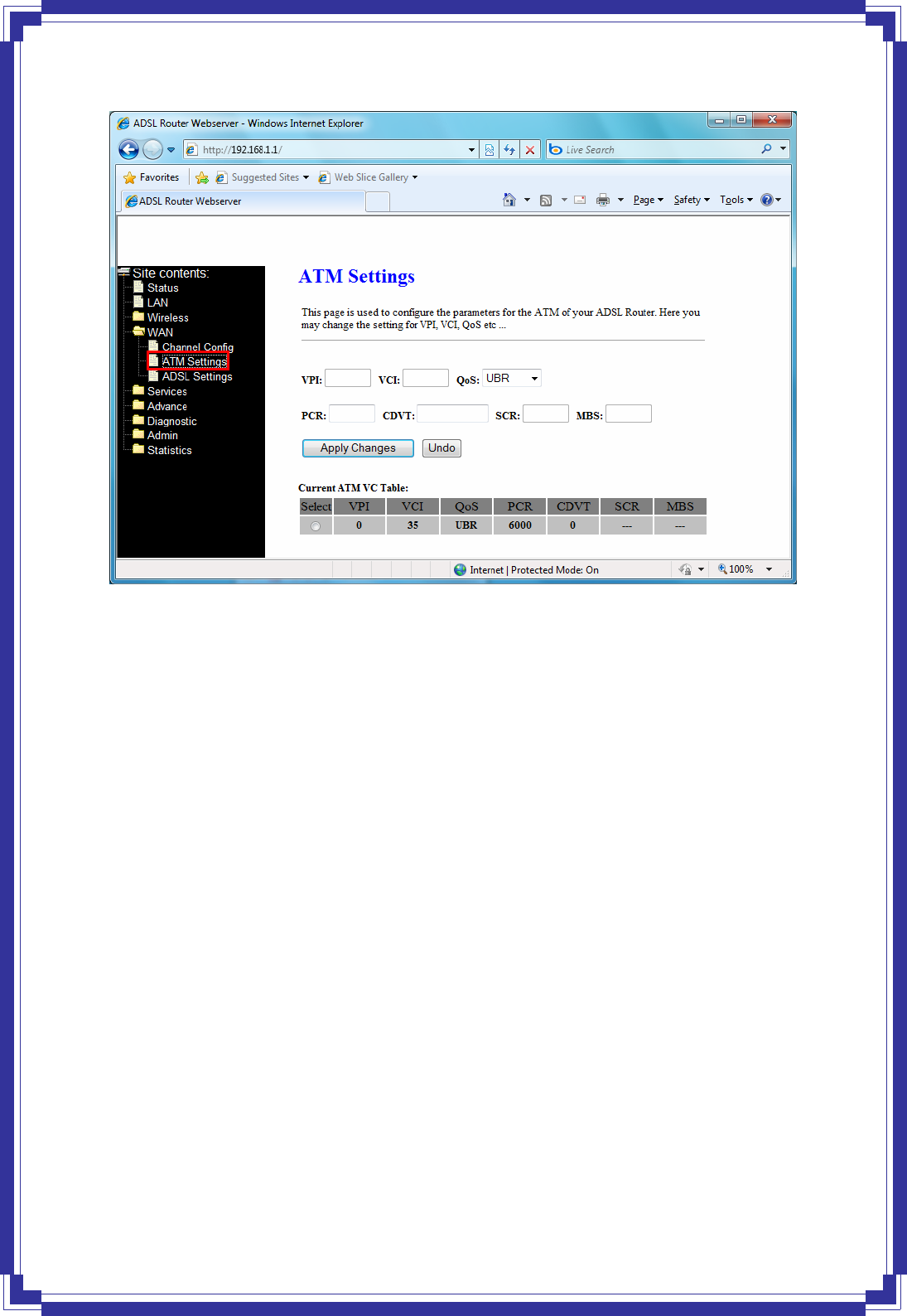
4.5.2 ATM Settings
This page is for ATM PVC QoS parameters setting. The DSL device supports 4 QoS modes –
CBR, rt-VBR, nrt-VBR, and UBR.
38
VPI -- Virtual Path Identifier. This is read-only field and is selected on the Select column in
the Current ATM VC Table.
VCI -- Virtual Channel Identifier. This is read-only field and is selected on the Select
column in the Current ATM VC Table. The VCI, together with VPI, is used to identify
the next destination of a cell as it passes through to the ATM switch.
QoS -- Quality of Server, a characteristic of data transmission that measures how accurately
and how quickly a message or data is transferred from a source host to a destination
host over a network. The four QoS options are:
− UBR (Unspecified Bit Rate): When UBR is selected, the SCR and MBS fields are
disabled.
− CBR (Constant Bit Rate): When CBR is selected, the SCR and MBS fields are
disabled.
− nrt-VBR (non-real-time Variable Bit Rate): When nrt-VBR is selected, the SCR and
MBS fields are enabled.
− rt-VBR (real-time Variable Bit Rate): When rt-VBR is selected, the SCR and MBS
fields are enabled.
PCR -- Peak Cell Rate, measured in cells/sec., is the cell rate which the source may never
exceed.
SCR -- Sustained Cell Rate, measured in cells/sec., is the average cell rate over the duration
of the connection.