Pro Nets Technology WA41R Wireless ADSL 2+ ROUTER User Manual
Pro-Nets Technology Corporation Wireless ADSL 2+ ROUTER
Contents
- 1. user manual 1
- 2. user manual 2
- 3. user manual 3
- 4. user manual 4
user manual 3
39
MBS -- Maximum Burst Size, a traffic parameter that specifies the maximum number of cells
that can be transmitted at the peak cell rate.
Apply Changes -- Set new PVC OoS mode for the selected PVC. New parameters will take
effect after save into flash memory and reboot the system. See section “Admin” for save
details.
Undo -- Discard your settings.
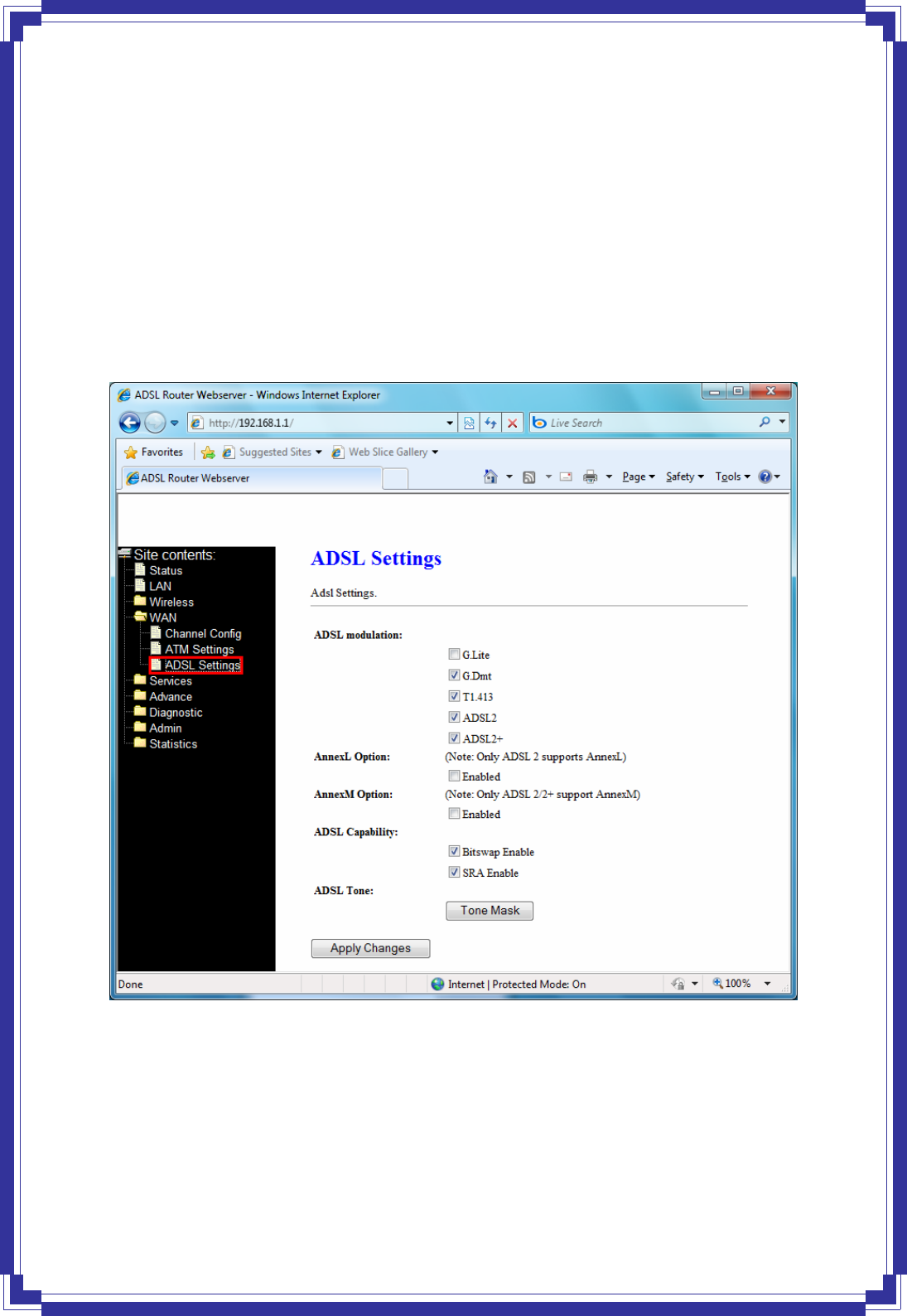
4.5.3 ADSL Settings
The ADSL Settings page allows you to select any combination of DSL training modes.
ADSL modulation -- Choose preferred xdsl standard protocols.
-- G.lite : G.992.2 Annex A
-- G.dmt : G.992.1 Annex A
-- T1.413 : T1.413 issue #2
-- ADSL2 : G.992.3 Annex A
-- ADSL2+ : G.992.5 Annex A

40
AnnexL Option -- Enable/Disable ADSL2/ADSL2+ Annex L capability
AnnexM Option -- Enable/Disable ADSL2/ADSL2+ Annex M capability.
ADSL Capability -- “Bitswap Enable”: Enable/Disable bitswap capability.
“SRA Enable”: Enable/Disable SRA (seamless rate adaptation) capability.
Tone Mask -- Choose tones to be masked. Masked tones will not carry any data.
Apply Changes -- Click to save the setting to the configuration and the modem will be
retrained.
4.6 Service
There are three sub-menus for Service configuration: DHCP Settings, DNS, Firewall, UPnP,
and RIP.
4.6.1 DHCP
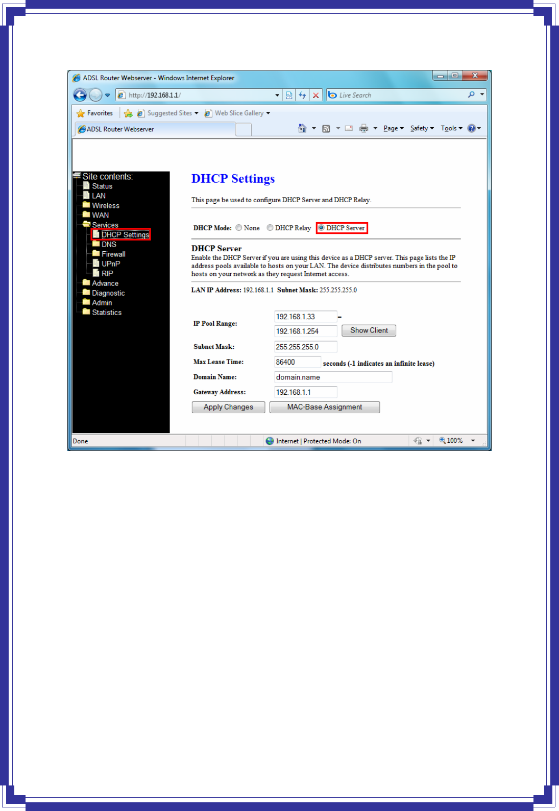
This page is used to configure [DHCP Relay] and [DHCP Server].
[DHCP Server]
By default, the device is configured as a DHCP server, with a predefined IP address pool of
192.168.1.2 through 192.168.1.100 (subnet mask 255.255.255.0).
41
IP Pool Range -- Specify the lowest and highest addresses in the pool.
Max Lease Time -- The Lease Time is the amount of time that a network user is allowed to
maintain a network connection to the device using the current dynamic IP address. At the end
of the Lease Time, the lease is either renewed or a new IP is issued by the DHCP server. The
amount of time is in units of seconds. The default value is 86400 seconds (1 day). The
value –1 stands for the infinite lease.
Domain Name -- A user-friendly name that refers to the group of hosts (subnet) that will be
assigned addresses from this pool.
Apply Changes -- Set new DHCP server configuration. New parameters will take effect after
save into flash memory and reboot the system.
Undo – Discard your changes.
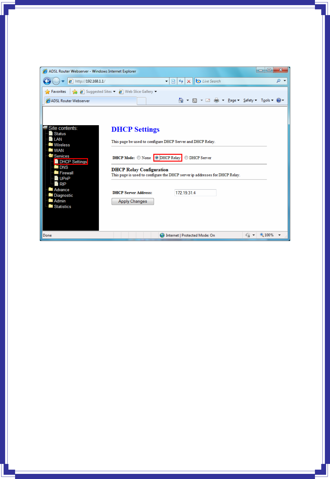
[DHCP Relay]
Some ISPs perform the DHCP server function for their customers’ home/small office network.
In this case, you can configure this device to act as a DHCP relay agent. When a host on your
network requests Internet access, the device contacts your ISP to obtain the IP configuration,
42
and then forward that information to the host. You should set the DHCP mode after you
configure the DHCP relay.
DHCP Mode -- Specify the IP address of your ISP’s DHCP server. Requests for IP information
from your LAN will be passed to the default gateway, which should route the request
appropriately.
Apply Changes -- Click to save the setting to the configuration.
4.6.2 DNS
There are two submenus for the DNS Configuration: [DNS Server] and [Dynamic DNS].
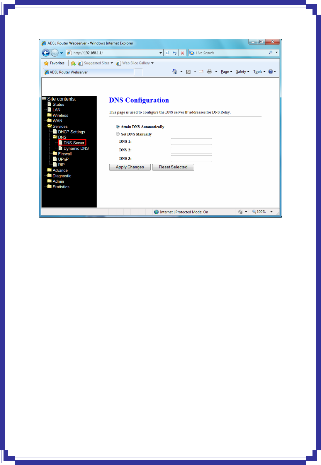
[DNS Server]
This page is used to select the way to obtain the IP addresses of the DNS servers.
43
Attain DNS Automatically -- Select this item if you want to use the DNS servers obtained by
the WAN interface via the auto-configuration mechanism.
Set DNS Manually -- Select this item to configure up to three DNS IP addresses.
Apply Changes -- Set new DNS relay configuration. New parameters will take effect after
save into flash memory and reboot the system.
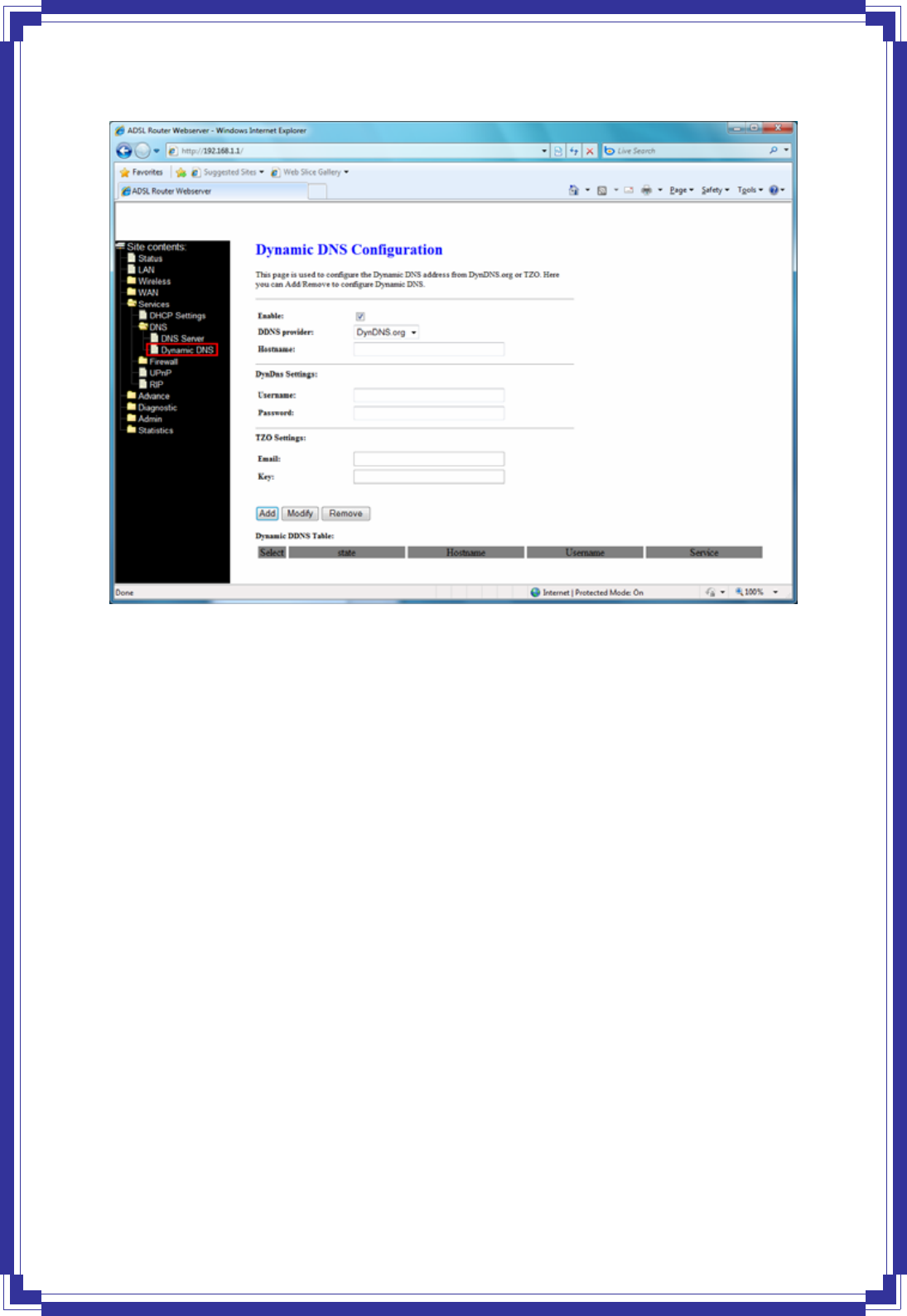
[Dynamic DNS]
Each time your device connects to the Internet, your ISP assigns a different IP address to your
device. In order for you or other users to access your device from the WAN-side, you need to
manually track the IP that is currently used. The Dynamic DNS feature allows you to register
your device with a DNS server and access your device each time using the same host name.
The Dynamic DNS page allows you to enable/disable the Dynamic DNS feature.
44
DDNS provider -- There are two DDNS providers to be selected in order to register your
device with: DynDNS and TZO. A charge may occur depends on the service you select.
Hostname -- Domain name to be registered with the DDNS server
User Name -- User-name assigned by the DDNS service provider.
Password -- Password assigned by the DDNS service provider.
Email -- Enter Email for TZO settings.
Key -- Enter key for TZO settings.
Add -- Click Add to add this registration into the configuration.
Remove -- Select an existing DDNS registration by clicking the radio button at the Select
column of the Dynamic DNS Table. Click Remove button to remove the selected registration
from the configuration.
4.6.3 Firewall
Firewall contains several features that are used to deny or allow traffic from passing through
the device.
4.6.3.1 IP/Port Filtering
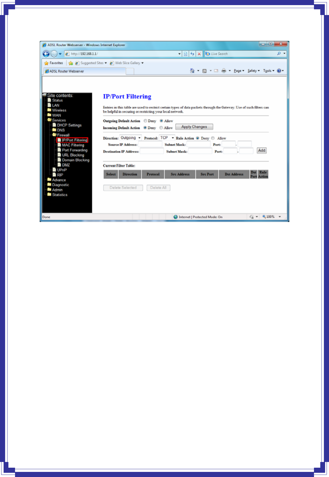
The IP/Port filtering feature allows you to deny/allow specific services or applications in the
forwarding path.
45
Outgoing Default Action -- Specify the default action on the LAN to WAN forwarding path.
Incoming Default Action -- Specify the default action on the WAN to LAN forwarding path.
Apply Changes -- Click to save the setting of default actions to the configuration.
Direction -- Traffic forwarding direction.
Protocol -- There are 3 options available: TCP, UDP and ICMP.
Rule Action -- Deny or allow traffic when matching this rule.
Source IP Address -- The source IP address assigned to the traffic on which filtering is
applied.
Source Subnet Mask -- Subnet-mask of the source IP.
Source Port -- Starting and ending source port numbers.
Destination IP Address -- The destination IP address assigned to the traffic on which filtering
is applied.
Destination Subnet Mask -- Subnet-mask of the destination IP.
Destination Port -- Starting and ending destination port numbers.
Delete Selected -- Delete selected filtering rules from the filter table. You can click the
checkbox at the Select column to select the filtering rule.
Delete All -- Delete all filtering rules from the filter table.
46
4.6.3.2 MAC Filtering
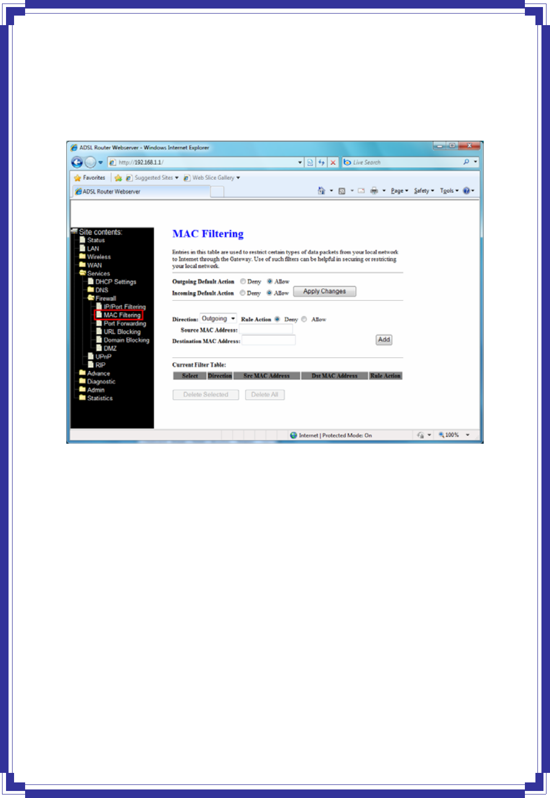
The MAC filtering feature allows you to define rules to allow or deny frames through the device
based on source MAC address, destination MAC address, and traffic direction.
Outgoing Default Action -- Specify the default action on the LAN to WAN bridging/forwarding
path.
Incoming Default Action -- Specify the default action on the WAN to LAN bridging/forwarding
path.
Apply Changes -- Click to save the setting of default actions to the configuration.
Direction -- Traffic bridging/forwarding direction.
Rule Action -- Deny or allow traffic when matching this rule.
Source MAC Address -- The source MAC address. It must be xxxxxxxxxxxx format. Blanks
can be used in the MAC address space and are considered as don’t care.
Destination MAC Address -- The destination MAC address. It must be xxxxxxxxxxxx format.
Blanks can be used in the MAC address space and are considered as don’t care.
Delete Selected -- Delete selected filtering rules from the filter table. You can click the
checkbox at the Select column to select the filtering rule.
Delete All -- Delete all filtering rules from the filter table.
47
4.6.3.3 Port Forwarding
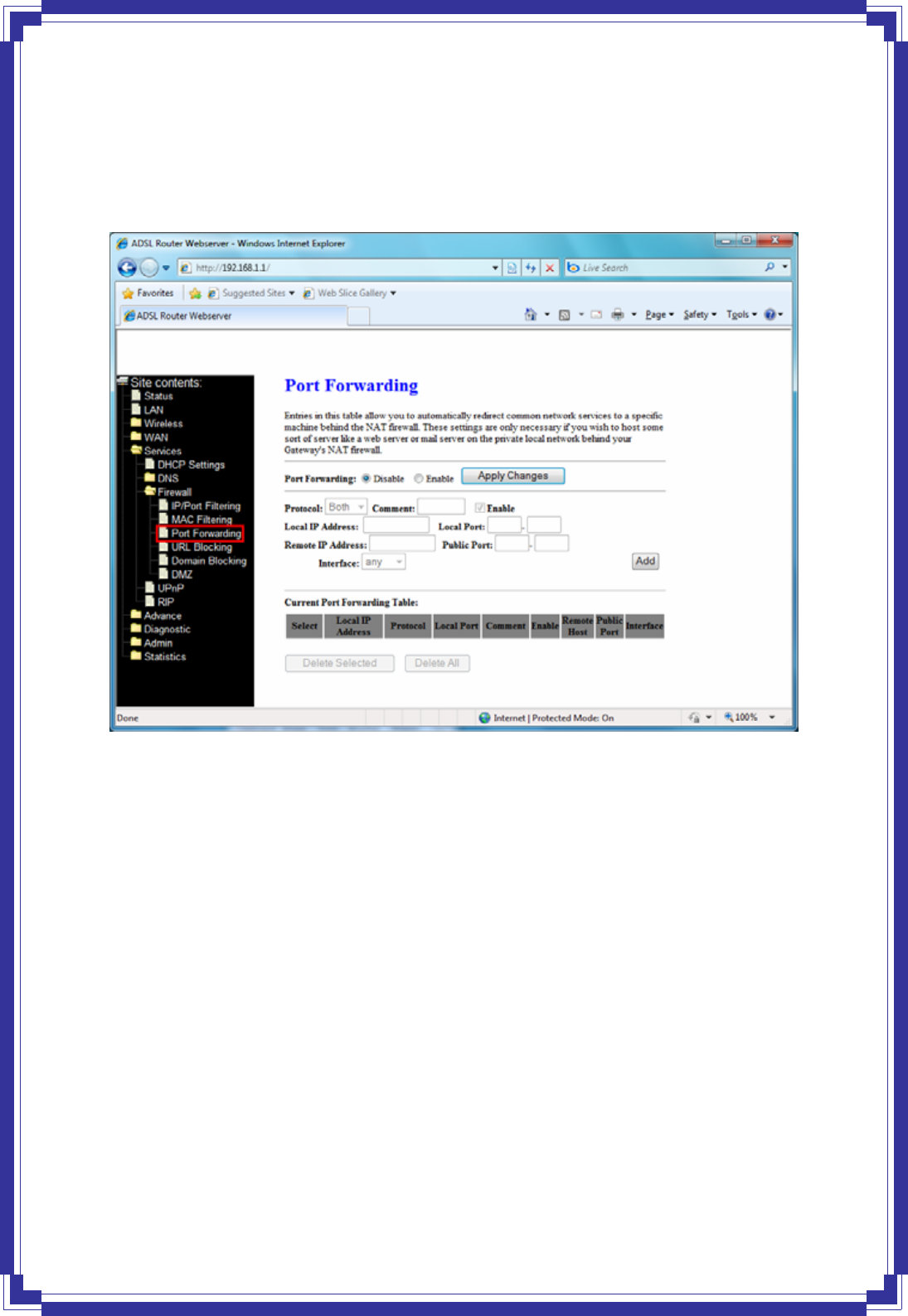
Firewall keeps unwanted traffic from the Internet away from your LAN computers. Add a Port
Forwarding entry will create a tunnel through your firewall so that the computers on the
Internet can communicate to one of the computers on your LAN on a single port.
Port Forwarding -- Check this item to enable or disable the port-forwarding feature.
Protocol -- There are 3 options available: TCP, UDP and Both.
Local IP Address -- IP address of your local server that will be accessed by Internet.
Local Port -- The destination port number that is made open for this application on the
LAN-side.
Remote IP Address -- The source IP address from which the incoming traffic is allowed.
Leave blank for all.
Public Port -- The destination port number that is made open for this application on the
WAN-side
Interface -- Select the WAN interface on which the port-forwarding rule is to be applied.
Apply Changes -- Click to save the rule entry to the configuration.
Delete Selected -- Delete the selected port forwarding rules from the forwarding table. You
can click the checkbox at the Select column to select the forwarding rule.
Delete All -- Delete all forwarding rules from the forwarding table.
48
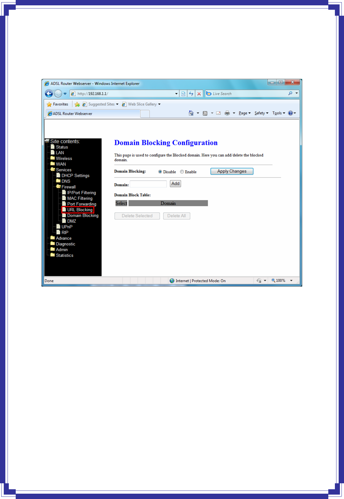
4.6.3.4 URL Blocking
This page is used to configure the Blocked FQDN (such as tw.yahoo.com) and filtered
keyword. Here you can add/delete FQDN and filtered keyword.
URL Blocking -- Check this item to enable or disable the URL Blocking feature.
Apply Changes -- Click to save the rule entry to the configuration.
FQDN -- Enter URL link which you want to filter in this section; and then click Add to save the
change.
Delete Selected -- Delete the selected URL Blocking rules from the table. You can click the
checkbox at the Select column to select the blocking rule.
Delete All -- Delete all URL blocking rules from the table.
Keyword -- Entry the keyword which you want to filter in this section; and then click Add to
save the change.
Delete Selected -- Delete the selected Keyword Filtering rules from the table. You can click
the checkbox at the Select column to select the filtering rule.
Delete All -- Delete all Keyword Filtering rules from the table.
49
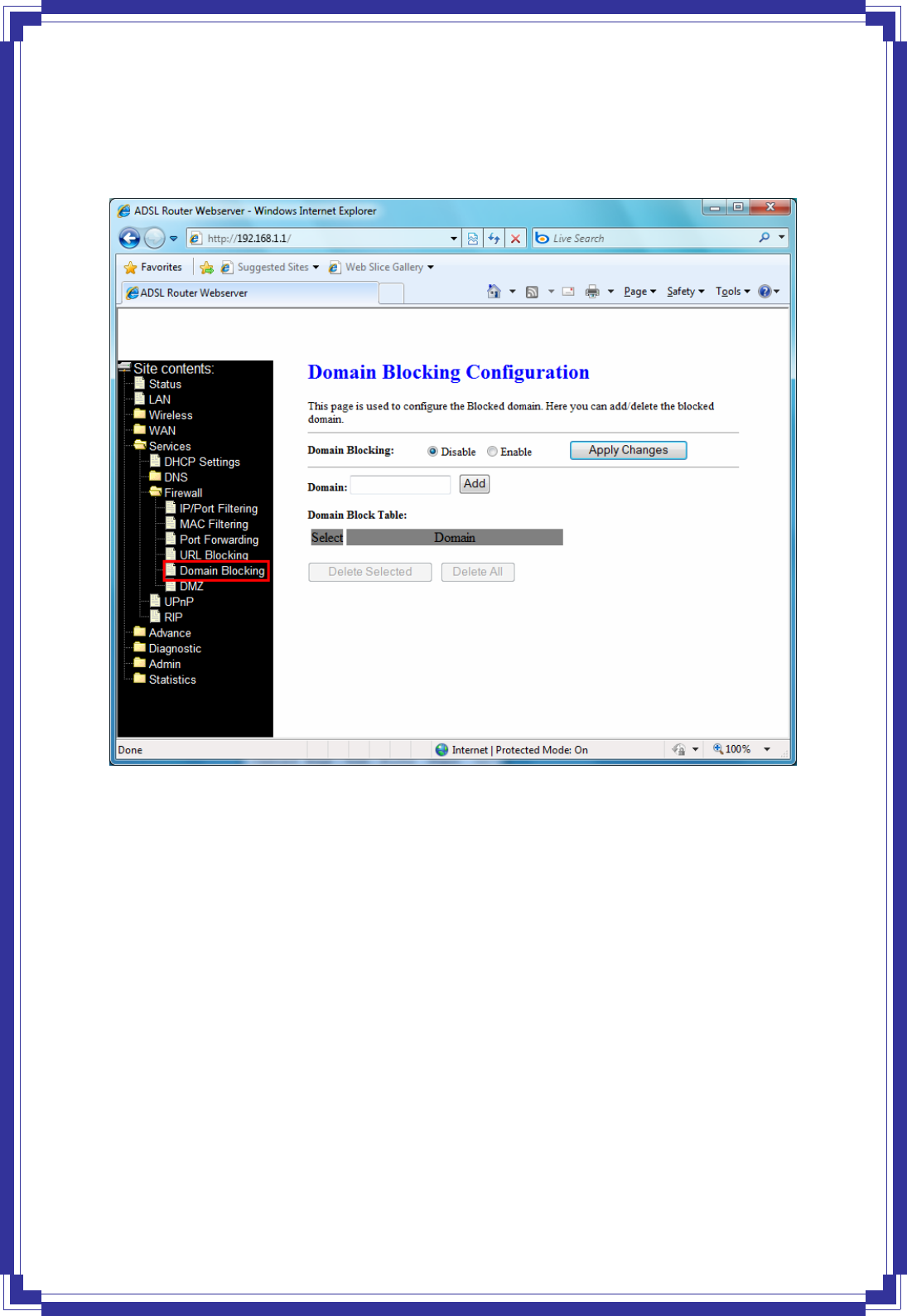
4.6.3.5 Domain Blocking
This page is used to configure the Blocked domain. Here you can add/delete the block
domain.
Domain Blocking -- Check this item to enable or disable the Domain Blocking feature.
Apply Changes -- Click to save the rule entry to the configuration.
Domain -- A user-friendly name that refers to the group of hosts (subnet) that will be blocked.
Delete Selected -- Delete the selected Domain Blocking rules from the table. You can click the
checkbox at the Select column to select the filtering rule.
Delete All -- Delete all Domain Blocking rules from the table.
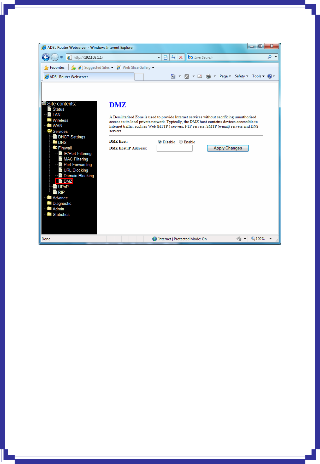
4.6.3.6 DMZ
A DMZ (Demilitarized Zone) allows a single computer on your LAN to expose ALL of its ports
to the Internet. Enter the IP address of that computer as a DMZ (Demilitarized Zone) host
with unrestricted Internet access. When doing this, the DMZ host is no longer behind the
firewall.
50
DMZ Host -- Check this item to enable the DMZ feature.
DMZ Host IP Address -- IP address of the local host. This feature sets a local host to be
exposed to the Internet.
Apply Changes -- Click to save the setting to the configuration.
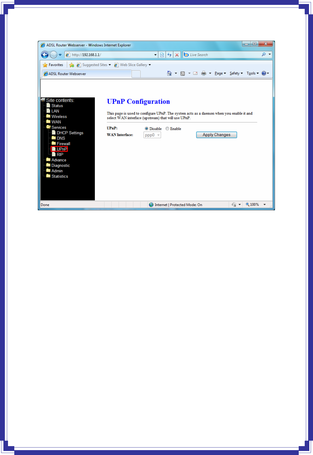
4.6.4 UPnP
The DSL device supports a control point for Universal Plug and Play (UPnP) version 1.0, and
supports two key features: NAT Traversal and Device Identification. This feature requires one
active WAN interface. In addition, the host should support this feature. In the presence of
multiple WAN interfaces, select an interface on which the incoming traffic is present.
With NAT Traversal, when an UPnP command is received to open ports in NAT, the
application translates the request into system commands to open the ports in NAT and the
firewall. The interface to open the ports on is given to UPnP when it starts up and is part of the
configuration of the application.
For Device Identification, the application will send a description of the DSL device as a control
point back to the host making the request.
51
UPnP -- Enable/disable UPnP feature.
WAN Interface -- Select WAN interface that will use UPnP from the drop-down lists.
Apply Changes -- Click to save the setting to the system configuration.
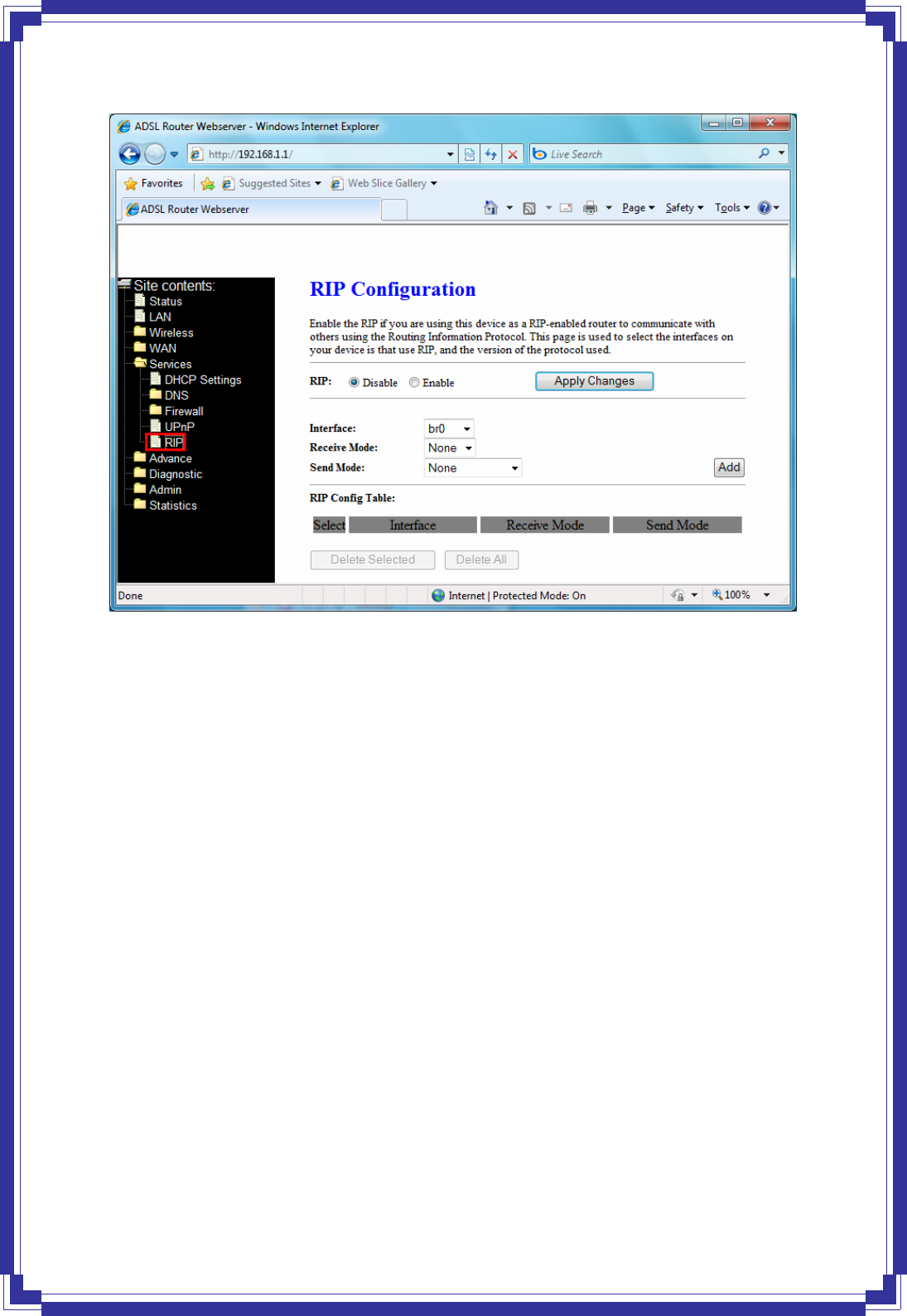
4.6.5 RIP
RIP is an Internet protocol you can set up to share routing table information with other routing
devices on your LAN, at your ISP’s location, or on remote networks connected to your network
via the ADSL line.
Most small home or office networks do not need to use RIP; they have only one router, such as
the ADSL Router, and one path to an ISP. In these cases, there is no need to share routes,
because all Internet data from the network is sent to the same ISP gateway.
You may want to configure RIP if any of the following circumstances apply to your network:
− Your home network setup includes an additional router or RIP-enabled PC (other than
the ADSL Router). The ADSL Router and the router will need to communicate via RIP to
share their routing tables.
− Your network connects via the ADSL line to a remote network, such as a corporate
network. In order for your LAN to learn the routes used within your corporate network,
they should both be configured with RIP.
− Your ISP requests that you run RIP for communication with devices on their network.
52
RIP -- Enable/disable RIP feature.
Apply Changes -- Click to save the setting of this setting block to the system configuration
Interface -- The name of the interface on which you want to enable RIP.
Receive Mode -- Indicate the RIP version in which information must be passed to the DSL
device in order for it to be accepted into its routing table.
Send Mode -- Indicate the RIP version this interface will use when it sends its route
information to other devices.
Add -- Add a RIP entry and the new RIP entry will be display in the table
Delete Selected -- Delete a selected RIP entry. The RIP entry can be selected on the Select
column of the RIP Config Table.
Delete All -- Delete all RIP rules from the table.
4.7 Advance
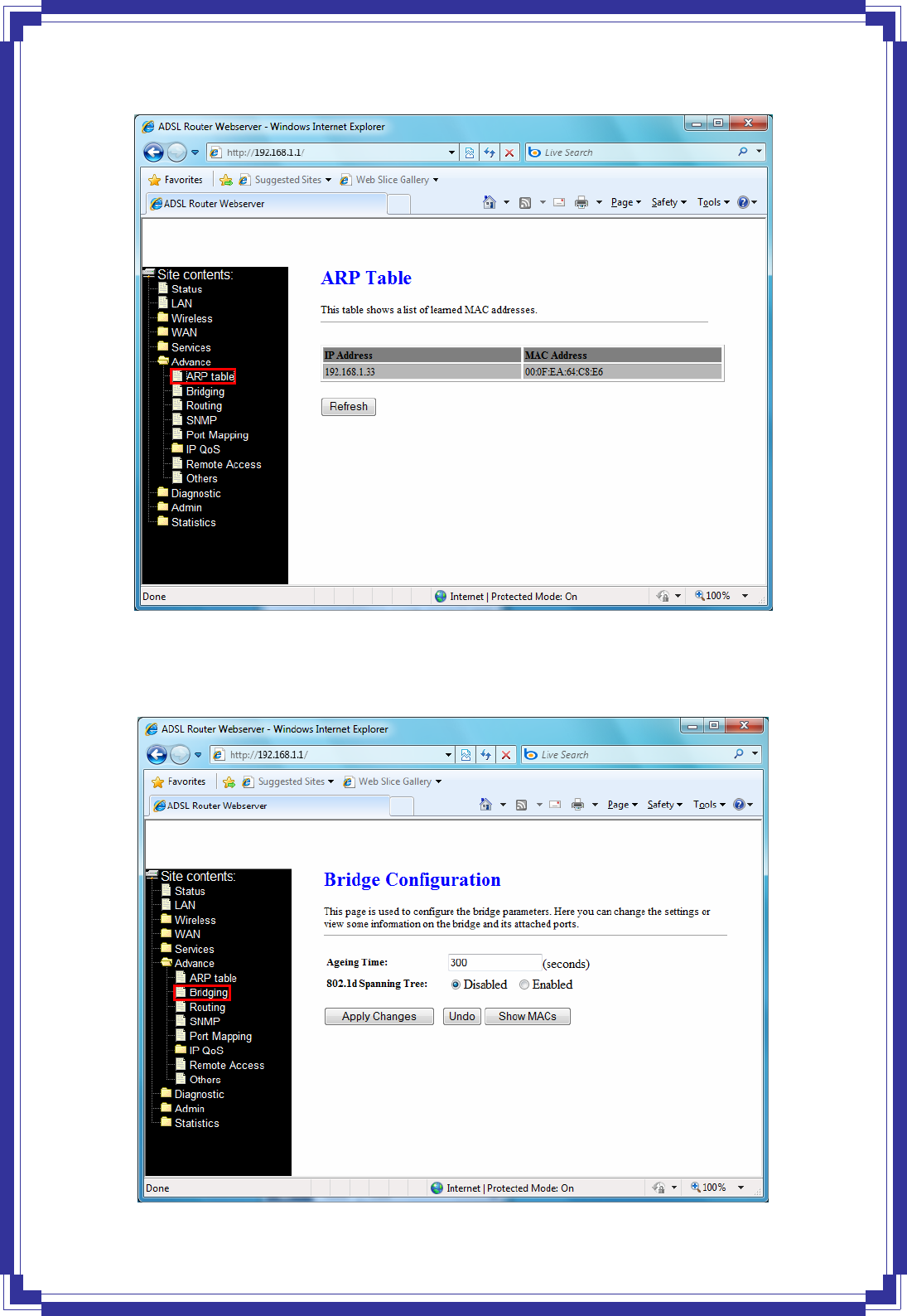
4.7.1 ARP Table
This table shows a list of learned MAC address.
53
4.7.2 Bridging
You can enable/disable Spanning Tree Protocol and set MAC address aging time in this page.

54
Ageing Time -- Set the Ethernet address ageing time, in seconds. After [Ageing Time]
seconds of not having seen a frame coming from a certain address, the bridge will time out
(delete) that address from Forwarding DataBase(fdb).
802.1d Spanning Tree -- Enable/disable the spanning tree protocol
Apply Changes -- Save this bridge configuration. New configuration will take effect after
saving into flash memory and rebooting the system.
Show MACs -- List MAC address in forwarding table.
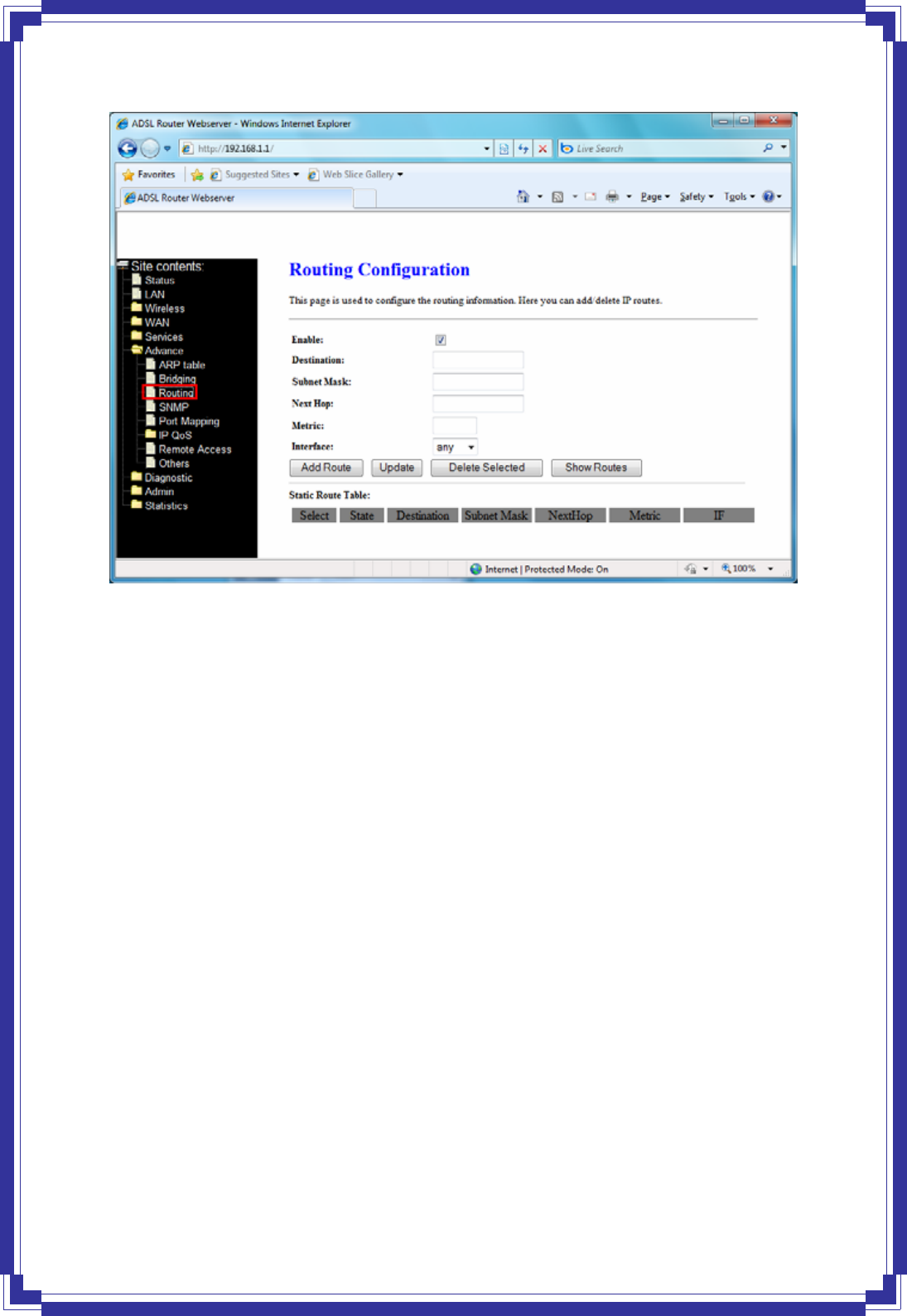
4.7.3 Routing
The Routing page enables you to define specific route for your Internet and network data. Most
users do not need to define routes. On a typical small home or office LAN, the existing routes
that set up the default gateways for your LAN hosts and for the DSL device provide the most
appropriate path for all your Internet traffic.
− On your LAN hosts, a default gateway directs all Internet traffic to the LAN port(s) on
the DSL device. Your LAN hosts know their default gateway either because you assigned
it to them when you modified your TCP/IP properties, or because you configured them to
receive the information dynamically from a server whenever they access the Internet.
− On the DSL device itself, a default gateway is defined to direct all outbound Internet
traffic to a route at your ISP. The default gateway is assigned either automatically by your
ISP whenever the device negotiates an Internet access, or manually by user to setup
through the configuration.
You may need to define routes if your home setup includes two or more networks or subnets, if
you connect to two or more ISP services, or if you connect to a remote corporate LAN.
55
Enable -- Check to enable the selected route or route to be added.
Destination -- The network IP address of the subnet. The destination can be specified as the
IP address of a subnet or a specific host in the subnet. It can also be specified as all zeros to
indicate that this route should be used for all destinations for which no other route is defined
(this is the route that creates the default gateway).
Subnet Mask -- The network mask for the destination subnet. The default gateway uses a
mask of 0.0.0.0.
Next Hop -- The IP address of the next hop through which traffic will flow towards the
destination subnet.
Metric -- Defines the number of hops between network nodes that data packets travel. The
default value is 0, which means that the subnet is directly one hop away on the local LAN
network.
Interface -- The WAN interface for a static routing subnet is to be applied.
Add Route -- Add a user-defined destination route.
Update -- Update the selected destination route on the Static Route Table.
Delete Selected -- Delete a selected destination route on the Static Route Table.
Show Routes -- Click this button to view the DSL device’s routing table.
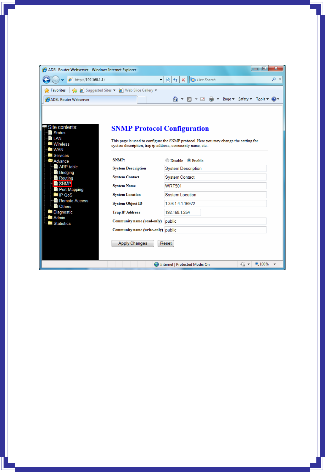
4.7.4 SNMP
Simple Network Management Protocol (SNMP) is a troubleshooting and management protocol
56
that uses the UDP protocol on port 161 to communicate between clients and servers. The DSL
device can be managed locally or remotely by SNMP protocol.
SNMP -- Enable/disable RIP feature.
System Description -- System descriptions of the DSL device.
System Contact -- Contact person and/or contact information for the DSL device.
System Name -- An administratively assigned name for the DSL device.
System Location -- The physical locations of the DSL device.
System Object ID -- Vendor object identifier. The vendor’s authoritative identifications of the
network management sub-system contained in the entity.
Trap IP Address -- Destination IP address of the SNMP trap.
Community name (read-only) – Name of the read-only community. This read-only
community allows read operation to all objects in the MIB.
Community name (write-only) -- Name of the write-only community. This write-only
community allows write operation to the objects defines as read-writable in the MIB.
Apply Changes -- Save SNMP configuration. New configuration will take effect after saving
into flash memory and rebooting the system.

57
4.7.5 Port Mapping
To manipulate a mapping group:
(1) Select a group from the table
(2) Select interfaces from the available/grouped interface list and add it to the
grouped/available interface list using the arrow buttons to manipulate the required
mapping of the ports.
(3) Click “Apply Changes” button to save the changes.
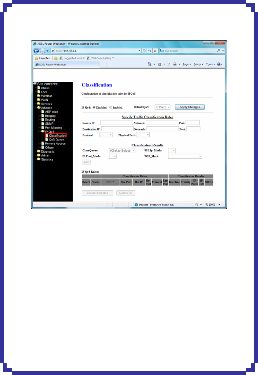
4.7.6 IP QoS
The DSL device provides a control mechanism that can provide different priority to different
users or data flows. The QoS is enforced by the QoS rules in the QoS table. A QoS rule
contains two configuration blocks: Traffic Classification and Action. The Traffic
Classification enables you to classify packets on the basis of various fields in the packet and
perhaps the physical ingress port. The Action enables you to assign the strictly priority level
for and mark some fields in the packet that matches the Traffic Classification rule.
You can configure any or all field as needed in these two QoS blocks for a QoS rule.
58
[Classification]
IP QoS -- Enable/disable the IP QoS function.
Source IP -- The IP address of the traffic source.
Source Netmask --The source IP netmask. This field is required if the source IP has been
entered.
Source Port -- The source port of the selected protocol. You cannot configure this field
without entering the protocol first.
Destination IP -- The IP address of the traffic destination.
Destination Netmask -- The destination IP netmask. This field is required if the destination IP
has been entered.
Destination Port -- The destination port of the selected protocol. You cannot configure this
field without entering the protocol first.
Protocol -- The selections are TCP, UDP, ICMP and the blank for none. This field is required if
the source port or destination port has been entered.
Physical Port -- The incoming ports. The selections include LAN ports, wireless port, and the
blank for not applicable.