ProSoft Technology OS2401 Locus 802.11b MiniPCI Radio Module with Amplifier User Manual Module Users Guide
ProSoft Technology, Inc Locus 802.11b MiniPCI Radio Module with Amplifier Module Users Guide
UserManual.wiki
>
ProSoft Technology
>
OS2401 User Manual
Users Manual
Navigation menu
Upload a User Manual
Namespaces
Wiki Guide
HTML
PDF
Info
Views
User Manual
Discussion / Help
Navigation
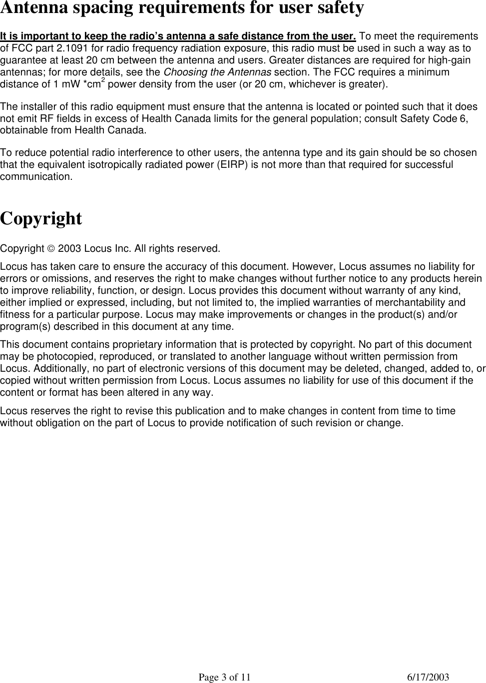
![Page 6 of 11 6/17/2003 Module Connections Mini-PCI Port Digital connection is through Mini PCI type III defined by the Mini PCI Specification document published by the PCI Special Interest Group. As a recommendation, the Molex 67315-0011 can be used. Pin Signal Pin Signal Pin Signal Pin Signal 1 TIP 2 RING 63 3.3V 64 FRAME# Key Key 3 8PMJ-33, 4 4 8PMJ-13, 4 65 CLKRUN# 66 TRDY# 5 8PMJ-63, 4 6 8PMJ-23, 4 67 SERR# 68 STOP# 7 8PMJ-73, 4 8 8PMJ-43, 4 69 GROUND 70 3.3V 9 8PMJ-83, 4 10 8PMJ-53, 4 71 PERR# 72 DEVSEL# 11 LED1_GRNP 12 LED2_YELP 73 C/BE[1]# 74 GROUND 13 LED1_GRNN 14 LED2_YELN 75 AD[14] 76 AD[15] 15 CHSGND 16 RESERVED 77 GROUND 78 AD[13] 17 INTB# 18 5V 79 AD[12] 80 AD[11] 19 3.3V 20 INTA# 81 AD[10] 82 GROUND 21 RESERVED 22 RESERVED 83 GROUND 84 AD[09] 23 GROUND 24 3.3VAUX 85 AD[08] 86 C/BE[0]# 25 CLK 26 RST# 87 AD[07] 88 3.3V 27 GROUND 28 3.3V 89 3.3V 90 AD[06] 29 REQ# 30 GNT# 91 AD[05] 92 AD[04] 31 3.3V 32 GROUND 93 RESERVED 94 AD[02] 33 AD[31] 34 PME# 95 AD[03] 96 AD[00] 35 AD[29] 36 RESERVED 97 5V 98 RESERVED_WIP5 37 GROUND 38 AD[30] 99 AD[01] 100 RESERVED_WIP5 39 AD[27] 40 3.3V 101 GROUND 102 GROUND 41 AD[25] 42 AD[28] 103 AC_SYNC 104 M66EN 43 RESERVED 44 AD[26] 105 AC_SDATA_IN 106 AC_SDATA_OUT 45 C/BE[3]# 46 AD[24] 107 AC_BIT_CLK 108 AC_CODEC_ID0# 47 AD[23] 48 IDSEL 109 AC_CODEC_ID1# 110 AC_RESET# 49 GROUND 50 GROUND 111 MOD_AUDIO_MON 112 RESERVED 51 AD[21] 52 AD[22] 113 AUDIO_GND 114 GROUND 53 AD[19] 54 AD[20] 115 SYS_AUDIO_OUT 116 SYS_AUDIO_IN 55 GROUND 56 PAR 117 SYS_AUDIO_OUT GND 118 SYS_AUDIO_IN GND 57 AD[17] 58 AD[18] 119 AUDIO_GND 120 AUDIO_GND 59 C/BE[2]# 60 AD[16] 121 RESERVED 122 MPCIACT# 61 IRDY# 62 GROUND 123 VCC5VA 124 3.3VAUX The signal CHSGND is a chassis ground contact and is connected on the Mini PCI Card via a spring contact clip. Antenna Port Two antenna port connections (for diversity) are provided. The radio uses SMT Ultra Miniature Coax Connector, Hirose, CL331-0471-0-10 (U.FL-R-SMT). The interface board contains two of these connectors as well. The radio is connected to the interface board through a Hirose cable. The preferred part number is U.FL-2LP-5016-A-150.](https://usermanual.wiki/ProSoft-Technology/OS2401/User-Guide-335566-Page-6.png)