ProSoft Technology OS2401 Locus 802.11b MiniPCI Radio Module with Amplifier User Manual Module Users Guide
ProSoft Technology, Inc Locus 802.11b MiniPCI Radio Module with Amplifier Module Users Guide
Users Manual

Locus OS2401
802.11b MiniPCI Radio Module with
Amplifier
User’s Guide
June 17, 2003
Page 2 of 11 6/17/2003
REGULATORY APPROVALS
United States FCC & Industry Canada rules
Compliance Statement
The following statements must be included in the product documentation for the end device in which the
radio module is embedded:
This device complies with Part 15 of the FCC Rules. Operation is subject to the following
two conditions: (1) this device may not cause harmful interference, and (2) this device
must accept any interference received, including interference that may cause undesired
operation.
NOTE: This equipment has been tested and found to comply with the limits for a Class A digital device,
pursuant to Part 15 of the FCC Rules. These limits are designed to provide reasonable protection against
harmful interference when the equipment is operated in a commercial environment. This equipment
generates, uses, and can radiate radio frequency energy and, if not installed and used in accordance with
the instruction manual, may cause harmful interference to radio communications. Operation of this
equipment in a residential area is likely to cause harmful interference in which case the user will be
required to correct the interference at his own expense.
Product Labeling
This radio module is labeled with an FCC ID number and a Canadian Certification Number. If this
label is not visible when installed in an end-device, the outside of the device MUST also display a
label referring to the enclosed OS2401. Use wording on the label similar to the following:
"Transmitter Module FCC ID: OQ7OS2401, Canada 3656AOS2401".
OR
"This device contains Transmitter Module FCC ID: OQ7OS2401, Canada 3656AOS2401"
CAUTION: Changes or modifications to this radio module not expressly approved by its manufacturer,
Locus, Inc., may void the user’s authority to operate the equipment.
NOTES:
• Only approved antennas and power amplifier listed in this manual may be used with the OS2401.
• The OS2400 Radio Module does not need to be re-authorized for compliance with Part 15,C
intentional radiation (15.247 spread spectrum rules) or Part 15, B unintentional radiation. However, if
the device into which the module is inserted contains any frequency sources (oscillator, clocks, etc.) it
will have to be verified according to Part 15, B unintentional radiation to make sure that it does not
unintentionally radiate.

Page 3 of 11 6/17/2003
Antenna spacing requirements for user safety
It is important to keep the radio’s antenna a safe distance from the user. To meet the requirements
of FCC part 2.1091 for radio frequency radiation exposure, this radio must be used in such a way as to
guarantee at least 20 cm between the antenna and users. Greater distances are required for high-gain
antennas; for more details, see the Choosing the Antennas section. The FCC requires a minimum
distance of 1 mW *cm2 power density from the user (or 20 cm, whichever is greater).
The installer of this radio equipment must ensure that the antenna is located or pointed such that it does
not emit RF fields in excess of Health Canada limits for the general population; consult Safety Code 6,
obtainable from Health Canada.
To reduce potential radio interference to other users, the antenna type and its gain should be so chosen
that the equivalent isotropically radiated power (EIRP) is not more than that required for successful
communication.
Copyright
Copyright 2003 Locus Inc. All rights reserved.
Locus has taken care to ensure the accuracy of this document. However, Locus assumes no liability for
errors or omissions, and reserves the right to make changes without further notice to any products herein
to improve reliability, function, or design. Locus provides this document without warranty of any kind,
either implied or expressed, including, but not limited to, the implied warranties of merchantability and
fitness for a particular purpose. Locus may make improvements or changes in the product(s) and/or
program(s) described in this document at any time.
This document contains proprietary information that is protected by copyright. No part of this document
may be photocopied, reproduced, or translated to another language without written permission from
Locus. Additionally, no part of electronic versions of this document may be deleted, changed, added to, or
copied without written permission from Locus. Locus assumes no liability for use of this document if the
content or format has been altered in any way.
Locus reserves the right to revise this publication and to make changes in content from time to time
without obligation on the part of Locus to provide notification of such revision or change.
Page 4 of 11 6/17/2003
Table of Contents
REGULATORY APPROVALS ................................................................................................................................ 2
UNITED STATES FCC & INDUSTRY CANADA RULES ................................................................................................. 2
Compliance Statement .......................................................................................................................................... 2
Product Labeling .................................................................................................................................................. 2
ANTENNA SPACING REQUIREMENTS FOR USER SAFETY.............................................................................................. 3
COPYRIGHT ............................................................................................................................................................... 3
PRODUCT OVERVIEW........................................................................................................................................... 5
MODULE INTEGRATION....................................................................................................................................... 5
MODULE PHYSICAL DIMENSIONS .............................................................................................................................. 5
MODULE CONNECTIONS ............................................................................................................................................ 6
Mini-PCI Port....................................................................................................................................................... 6
Antenna Port......................................................................................................................................................... 6
ANTENNAS AND AMPLIFIER USE ...................................................................................................................... 7
BI DIRECTIONAL AMPLIFIER...................................................................................................................................... 7
CHOOSING THE ANTENNAS........................................................................................................................................ 8
Approved Antennas............................................................................................................................................... 8
ANTENNA DESCRIPTIONS .......................................................................................................................................... 8
Antenna pattern .................................................................................................................................................... 9
Antenna gain......................................................................................................................................................... 9
Antenna polarity ................................................................................................................................................. 10
Antenna Types..................................................................................................................................................... 10
Page 5 of 11 6/17/2003
Product Overview
The Locus OS2401 is an 802.11b MiniPCI radio that has been approved by the FCC for use with an
external amplifier. The MiniPCI radio can be integrated into industrial devices to provide 802.11b wireless
connectivity.
Module Integration
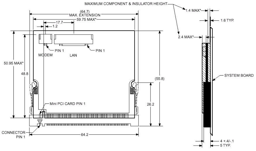
Module Physical Dimensions
The diagram below shows the dimensions of a MiniPCI TypeIIIA card.
Page 6 of 11 6/17/2003
Module Connections
Mini-PCI Port
Digital connection is through Mini PCI type III defined by the Mini PCI Specification document published
by the PCI Special Interest Group. As a recommendation, the Molex 67315-0011 can be used.
Pin Signal Pin Signal Pin Signal Pin Signal
1 TIP 2 RING 63 3.3V 64 FRAME#
Key Key
3 8PMJ-33, 4 4 8PMJ-13, 4 65 CLKRUN# 66 TRDY#
5 8PMJ-63, 4 6 8PMJ-23, 4 67 SERR# 68 STOP#
7 8PMJ-73, 4 8 8PMJ-43, 4 69 GROUND 70 3.3V
9 8PMJ-83, 4 10 8PMJ-53, 4 71 PERR# 72 DEVSEL#
11 LED1_GRNP 12 LED2_YELP 73 C/BE[1]# 74 GROUND
13 LED1_GRNN 14 LED2_YELN 75 AD[14] 76 AD[15]
15 CHSGND 16 RESERVED 77 GROUND 78 AD[13]
17 INTB# 18 5V 79 AD[12] 80 AD[11]
19 3.3V 20 INTA# 81 AD[10] 82 GROUND
21 RESERVED 22 RESERVED 83 GROUND 84 AD[09]
23 GROUND 24 3.3VAUX 85 AD[08] 86 C/BE[0]#
25 CLK 26 RST# 87 AD[07] 88 3.3V
27 GROUND 28 3.3V 89 3.3V 90 AD[06]
29 REQ# 30 GNT# 91 AD[05] 92 AD[04]
31 3.3V 32 GROUND 93 RESERVED 94 AD[02]
33 AD[31] 34 PME# 95 AD[03] 96 AD[00]
35 AD[29] 36 RESERVED 97 5V 98 RESERVED_WIP5
37 GROUND 38 AD[30] 99 AD[01] 100 RESERVED_WIP5
39 AD[27] 40 3.3V 101 GROUND 102 GROUND
41 AD[25] 42 AD[28] 103 AC_SYNC 104 M66EN
43 RESERVED 44 AD[26] 105 AC_SDATA_IN 106 AC_SDATA_OUT
45 C/BE[3]# 46 AD[24] 107 AC_BIT_CLK 108 AC_CODEC_ID0#
47 AD[23] 48 IDSEL 109 AC_CODEC_ID1# 110 AC_RESET#
49 GROUND 50 GROUND 111 MOD_AUDIO_MON 112 RESERVED
51 AD[21] 52 AD[22] 113 AUDIO_GND 114 GROUND
53 AD[19] 54 AD[20] 115 SYS_AUDIO_OUT 116 SYS_AUDIO_IN
55 GROUND 56 PAR 117 SYS_AUDIO_OUT GND
118 SYS_AUDIO_IN GND
57 AD[17] 58 AD[18] 119 AUDIO_GND 120 AUDIO_GND
59 C/BE[2]# 60 AD[16] 121 RESERVED 122 MPCIACT#
61 IRDY# 62 GROUND 123 VCC5VA 124 3.3VAUX
The signal CHSGND is a chassis ground contact and is connected on the Mini PCI Card via a spring
contact clip.
Antenna Port
Two antenna port connections (for diversity) are provided. The radio uses SMT Ultra Miniature Coax
Connector, Hirose, CL331-0471-0-10 (U.FL-R-SMT). The interface board contains two of these
connectors as well.
The radio is connected to the interface board through a Hirose cable. The preferred part number is U.FL-
2LP-5016-A-150.
Page 7 of 11 6/17/2003
Antennas and Amplifier Use
Bi Directional Amplifier
A Bi-Directional Amplifier may be needed if an application requires long lengths of coaxial cable to reach
the antenna. The amplifier is designed to put maximum transmit power right at the antenna and boost the
received signal primarily to overcome the cable loss. Only the RF Linx 2400LX-0.5W approved amplifier
may be used.
Note: The RF Linx 2400LX-0.5W shall be marketed only in the system configuration with which the
amplifier is authorized and shall not be marketed as a separate product.
The amplifier is designed to operate with a coax cable loss between the radio and amplifier of 6.5dB to
20dB. Within this range, the output of the amplifier is always 1/2W regardless of the input level. The
amplifier may not be used with a cable loss of less than 6.5dB. The use of a cable less than 6.5dB will
result in violation of 47 CFR Part 15 Rules under which the equipment has been authorized. With more
than 20dB cable loss the amplifier will not turn on.
See the chart below for the minimum and maximum lengths of various cable types required when the Bi-
directional amp is used.
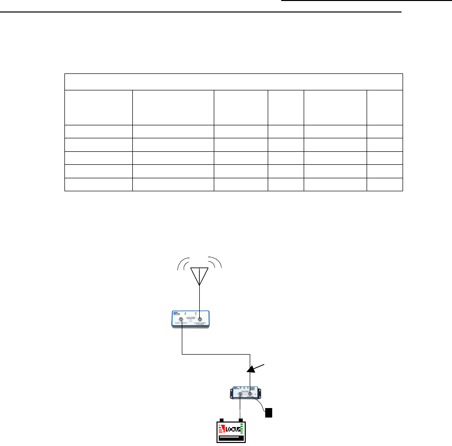
Proper installation of the amplifier and its power supply is shown below. The DC injector should be
located by the radio, and the amplifier should be at the antenna. The Bi-directional amp is weather proof
and can be mounted outdoors. See Bi-Directional amplifier instructions for more details.
Antenna Cable Type and lengths
Cable Type Cable loss/100'
(dB)
Minimum
length (ft) Loss
(dB) Maximum
length (ft) Loss
(dB)
LMR195 18.2 36 6.5 109 20
LMR400 6.9 94 6.5 289 20
LMR600 4.4 148 6.5 454 20
LDF4-50A 3.9 167 6.5 512 20
LDF5-50A 2 325 6.5 1000 20
DC power supply
Locus
OS2400HSE
Power amp DC
injector
RF BI-Directional
Amp
See chart for
minimum/maximum
cable lengths

Choosing the Antennas
Antenna section is dependent on whether the Bi-Directional amplifier is being used or not. The
minimum distance column in the tables below dictates how far the antennas must be separated from
users for safe exposure limits according to FCC Part 2.1091.
Approved Antennas
Antennas Approved for Use without Bi-Directional Amplifier
When the module is connected directly to an antenna, the following antennas may be used:
Antennas for Use with Amplifier
When the module is used in conjunction with the Amplifier, the antennas are limited to those below:
Note: To prevent high gain antennas from being used with an amplifier, Parabolic
antennas will not be sold if the user is ordering an amplifier.
* Mobile devices are defined by the FCC as transmitters designed to be used in other than fixed
locations and to generally be used in such a way that a separation distance of at least 20cm is normally
maintained between radiating structures and the body of the user or nearby persons. In the context, the
term “fixed location” means that the device is physically secured at one location and is not able to be
easily moved to another location. For fixed locations a separation distance of at least 1m is normally
maintained between radiating structures and the body of the user or nearby persons.
Antenna Pattern Locus Antenna Connector Typical Minimum
Type Part No. Gain Use* Distance
dBi
cm
½ Wave
Omni
540-0003
2
SMA-RP
Mobile
20
½ Wave, art.
Omni
540-0002
2
SMA-RP
Mobile
20
Collinear Array
Omni
540-0036
3
SMA-RP
Mobile
20
Collinear Array, art.
Omni
540-0005
5
SMA-RP
Mobile
20
Collinear Array
Omni
540-0006
8
N-RP
Mobile
20
Collinear Array
Omni
540-0037
9
N-RP
Mobile
20
Collinear Array
Omni
540-0038
12
N-RP
Mobile
20
Patch
Directional
540-0010
8
SMA-RP
Fixed
20
Patch
Directional
540-0011
11
SMA-RP
Fixed
20
Patch
Directional
540-0034
13
N-RP
Fixed
20
Patch
Directional
540-0035
19
N-RP
Fixed
34
Yagi
Directional
540-0009
13
N-RP
Fixed
20
Parabolic
Directional
540-0017
15
N-RP
Fixed
21
Parabolic
Directional
540-0018
19
N-RP
Fixed
34
Parabolic
Directional
540-0008
24
N-RP
Fixed
61
Antenna Pattern Locus Antenna Connector Typical Minimum
Type Part No. Gain Use* Distance
dBi
cm
½ Wave
Omni
540-0003
2
SMA-RP
Mobile
20
½ Wave, art.
Omni
540-0002
2
SMA-RP
Mobile
20
Collinear Array
Omni
540-0036
3
SMA-RP
Mobile
20
Collinear Array, art.
Omni
540-0005
5
SMA-RP
Mobile
20
Collinear Array
Omni
540-0006
8
N-RP
Mobile
20
Collinear Array
Omni
540-0037
9
N-RP
Mobile
20
Collinear Array
Omni
540-0038
12
N-RP
Fixed
23
Patch
Directional
540-0010
8
SMA-RP
Fixed
20
Patch
Directional
540-0011
11
SMA-RP
Fixed
21
Patch
Directional
540-0034
13
N-RP
Fixed
26
Yagi
Directional
540-0009
13
N-RP
Fixed
26
Page 9 of 11 6/17/2003
Antenna Descriptions
When selecting antennas to install with the OS2400-HSE in the U.S. and Canada, you can only use
models that are specifically approved by the U.S. Federal Communications Commission (FCC) and
Industry Canada. See Approved antennas for more details.
You must also consider three important electrical characteristics when selecting antennas:
• Antenna pattern
• Antenna gain
• Antenna polarity
Antenna pattern
Information between radios is transferred via electromagnetic energy radiated by one antenna and
received by the second. More power is radiated in certain directions from the antenna than others, a
phenomenon known as the antenna pattern. Each antenna should be mounted so the direction of strong
radiation intensity points toward the other antenna(s) to which it is linking.
Although complete antenna patterns are three-dimensional (3D), a two-dimensional (2D) slice of the
pattern is often shown because the antennas of interest are often located horizontally from one another,
along the ground rather than above or below each other.
A slice taken in a horizontal plane through the center (or looking down on the pattern) is called the
azimuth pattern. A vertical plane slice, which is seen from the side, is the elevation pattern.
An antenna pattern that has equal or nearly equal intensity in all directions is omnidirectional. In two
dimensions, an omnidirectional pattern is a circle. An antenna is considered omnidirectional if one of its
2D patterns is omnidirectional. (No antenna has an omnidirectional pattern in 3D.)
Beam width is an angular measurement of how strongly the power is concentrated in a particular
direction. Beam width is a 3D quantity, but it can be broken into 2D slices just like the antenna pattern.
The beam width of an omnidirectional pattern is 360°, because the power is equal in all directions.
Antenna gain
Antenna gain is a measure of how strongly an antenna radiates in its direction of maximum radiation
intensity compared to how strong the radiation would be if the same power were applied to an antenna
that radiated all of its power equally in all directions. Using the antenna pattern, the gain is the distance to
the furthest point on the pattern from the origin. For an omnidirectional pattern, the gain is 1, or
equivalently 0 dB. The higher the antenna gain is, the narrower the beam width, and vice versa.
The amount of power received by the receiving antenna is proportional to the transmitter power multiplied
by the transmit antenna gain, multiplied by the receiving antenna gain. Therefore, the antenna gains and
transmitting power can be traded off. For example, doubling one antenna gain has the same effect as
doubling the transmitting power. Doubling both antenna gains has the same effect as quadrupling the
transmitting power.
Page 10 of 11 6/17/2003
Antenna polarity
Antenna polarization refers to the direction in which the electromagnetic field lines point as energy
radiates away from the antenna. In general, the polarization is elliptical. The simplest and most common
form of this elliptical polarization is a straight line, or linear polarization. Of the transmitted power that
reaches the receiving antenna, only the portion that has the same polarization as the receiving antenna
polarization is actually received. For example, if the transmitting antenna polarization is pointed in the
vertical direction (vertical polarization, for short), and the receiving antenna also has vertical polarization,
the maximum amount of power possible will be received. On the other hand, if the transmit antenna has
vertical polarization and the receiving antenna has horizontal polarization, no power should be received. If
the two antennas have linear polarizations oriented at 45° to each other, half of the possible maximum
power will be received.
Antenna Types
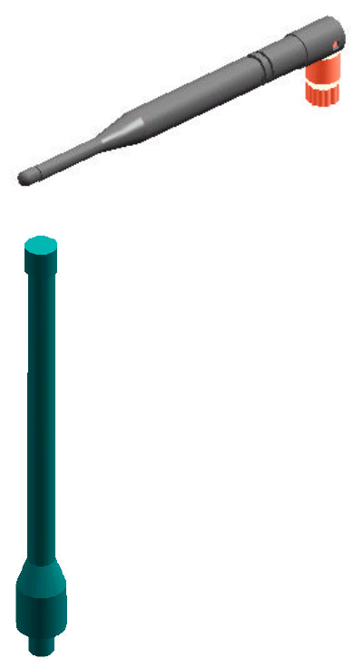
Whip antenna
You can use a 1/2λ straight whip or 1/2λ articulating whip (2 dBi) antenna with OS2400-HSE radios. These
antennas are the most common type in use today. Such antennas are approximately 5 inches long, and are
likely to be connected to a client radio (connected directly to the radio enclosure). These antennas do not
require a ground plane. Articulating antennas and non-articulating antennas work in the same way. An
articulating antenna bends at the connection.
Collinear array antenna
A collinear array antenna (shown at left) is typically composed of several linear antennas stacked
on top of each other. The more stacked elements it has, the longer it is, and the more gain it has.
It is fed in on one end.
The antenna pattern is torroidal. Its azimuthal beam width is 360° (omnidirectional). Its vertical
beam width depends on the number of elements/length, where more elements equal narrower
beam width. The antenna gain also depends on the number of elements/length, where more
elements produce higher gain. Typical gain is 5 to 10 dBi.
The antenna polarity is linear, or parallel to the length of the antenna.
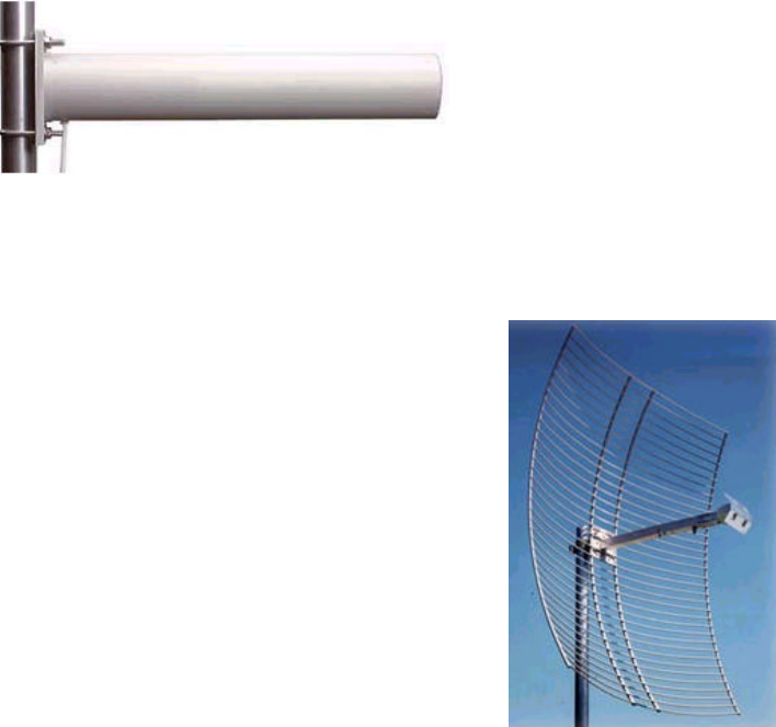
Yagi array antenna
A yagi antenna is composed of an array of linear elements, each parallel to one another and attached
perpendicular to and along the length of a metal boom. The feed is attached to only one of the elements.
Page 11 of 11 6/17/2003
Elements on one side of the fed element are longer and act as reflectors; elements on the other side are
shorter and act as directors. This causes the antenna pattern to radiate in a beam pointed along the
boom toward the end with the shorter elements. The pattern and beam width depend on the overall
antenna geometry, including the number of elements, element spacing, and element length, but they are
generally proportional to the length, where longer length produces a narrower beam. Sometimes the
antenna is enclosed in a protective tube that hides the actual antenna geometry.
The antenna gain also varies with antenna geometry, but generally is proportional to the length, where
longer length produces higher gain. Typical values are 6 to 15 dBi. The antenna polarity is linear (parallel
to the elements, perpendicular to the boom).
Parabolic reflector antenna
A parabolic reflector antenna consists of a parabolic shaped dish and a
feed antenna located in front of the dish. Power is radiated from the feed
antenna toward the reflector.
Due to the parabolic shape, the reflector concentrates the radiation into a
narrow pattern, resulting in a high-gain beam.
The antenna pattern is a beam pointed away from the concave side of the
dish. Beam width and antenna gain vary with the size of the reflector and
the antenna construction. Typical gain values are 15 to 30 dBi.
The antenna polarity depends on the feed antenna polarization.