Prodrive Technologies CCMUL Carrier Controller User Manual
Prodrive Technologies B.V. Carrier Controller
UserManual.wiki
>
Prodrive Technologies
>
CCMUL User Manual
>
User manual
Contents
1.
User manual
2.
Users Manual
User manual
Navigation menu
Upload a User Manual
Namespaces
Wiki Guide
HTML
PDF
Info
Views
User Manual
Discussion / Help
Navigation
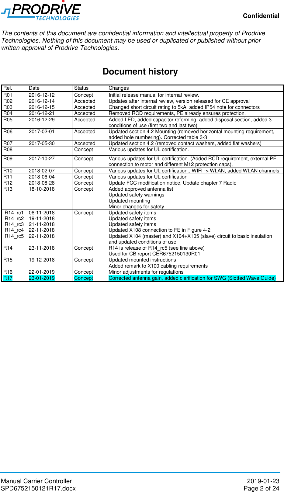
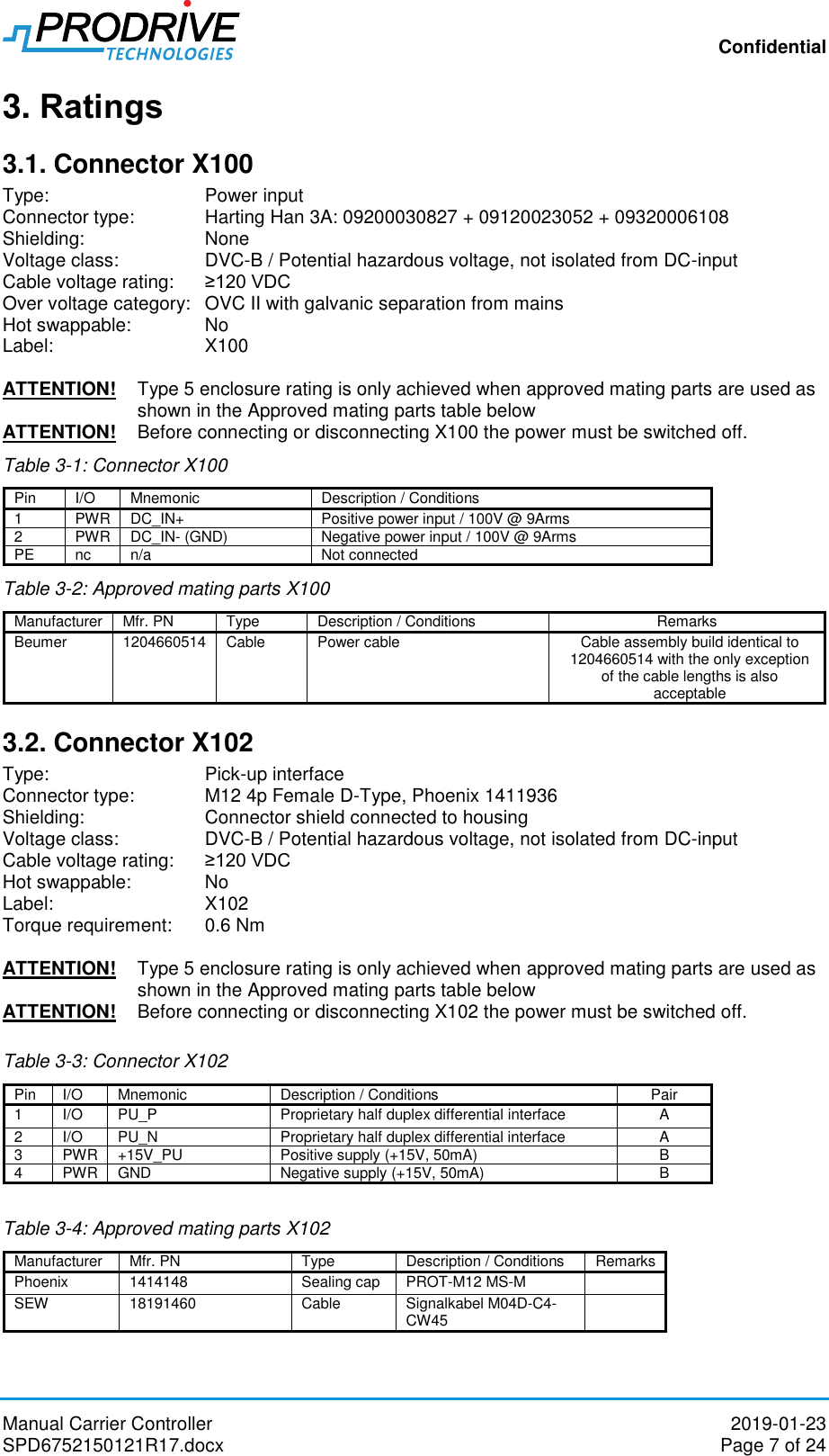
![Confidential Manual Carrier Controller 2019-01-23 SPD6752150121R17.docx Page 6 of 24 In case, the cable assemblies for X102, X103, X104, X105, X107, X108 and/or X109 are not installed on the product, each of the unused connector shall be closed with a sealing cap, PROT-M12 MS-M1414148 manufactured by Phoenix. These sealing caps shall also to be tightened with 0.6 Nm. The product is powered by a 100V DC power supply either isolated or non-isolated. The earthing system must be evaluated on system level for safe operation of the product. 2.1. General safety warnings CAUTION! During the UL evaluation, only Risk of Electrical Shock and Risk of Fire aspects were investigated. Functional Safety aspects were not evaluated CAUTION! Suitable For Use On A Circuit Capable Of Delivering Not More Than 5000 rms Symmetrical Amperes, 100 Volts DC Maximum CAUTION! Integral solid state short circuit protection does not provide branch circuit protection. Branch circuit protection must be provided in accordance with the National Electrical Code and any additional local codes CAUTION! High temperature on electronics housing, Risk of burns NOTICE: Changes or modifications made to this equipment not expressly approved by Prodrive Technologies B.V. may void the FCC authorization to operate this equipment. Table 2-1: Applicable safety norms Norm Description Label1 CSA-22.2 no. 274-17 Adjustable speed drives (Canada) UL 61800-5-1 Power conversion equipment (US) IEC-EN 61800-5-1 Adjustable Speed Electrical Power Drive Systems - Safety Requirements - Electrical, Thermal and Energy (Europe) Note[1]: Depending on model, only applicable if logo is present on product label](https://usermanual.wiki/Prodrive-Technologies/CCMUL.User-manual/User-Guide-4161973-Page-6.png)
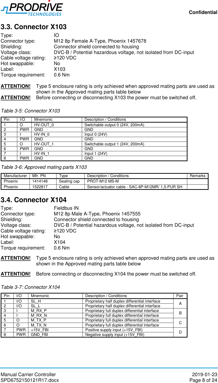
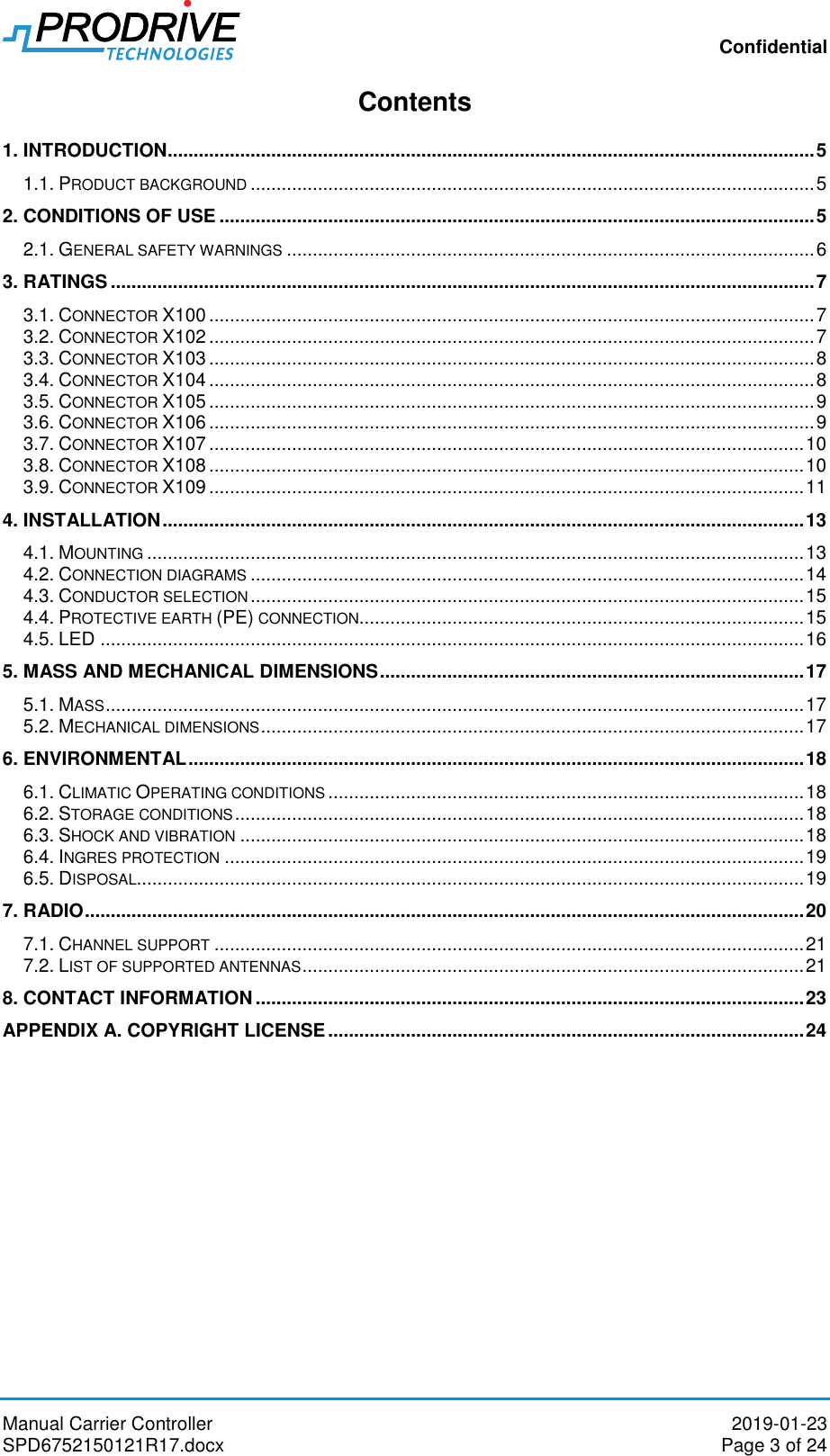
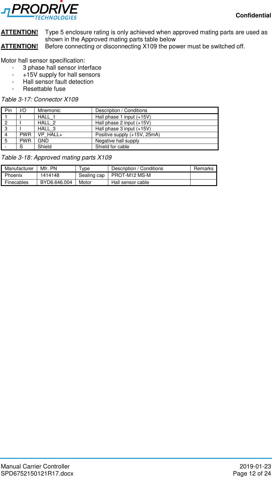
![Confidential Manual Carrier Controller 2019-01-23 SPD6752150121R17.docx Page 11 of 24 Table 3-14: Connector X108 Pin I/O Mnemonic Description / Conditions 1 O L1 Motor phase 1 output 2 O L2 Motor phase 2 output 3 O L3 Motor phase 3 output 4 FE FE FE connection - S Shield Shield for cable Motor output specification: 3 phases BLDC Protected against short circuit o No safety hazard o DC-Power-Bus is not shorted Functional protections o All protections disable end-stage if not mentioned otherwise o Instantaneous current (IPHASE,OCP) o RMS current (IPHASE,RMS) o DC-Power-Bus voltage Below VDC-POWER-BUS,NOSTART no movement is started Under voltage of DC-Power-Bus below VDC-POWER-BUS,UVP Over voltage of DC-Power-Bus above VDC-POWER-BUS,OVP o Temperature Over temperature of end-stage Table 3-15: Motor Interface electrical specifications Item Comments Min Typ Max Unit VDC-POWER-BUS,OVP Over voltage protection of DC-Power-Bus 120 [V] VDC-POWER-BUS,UVP Under voltage protection of DC-Power-Bus 30 [V] VDC-POWER-BUS Voltage of DC-Power-Bus 30 110 [V] VDC-POWER-BUS,NOSTART1 Voltage of DC-Power-Bus below which no movement is started 85 [V] IPHASE,RMS RMS phase current 6.5 [ARMS] IPHASE,LIMIT Adjustable phase peak current limit 10 45 [A] IPHASE,OCP Over current protection 45 [A] LMOTOR,PH-PH Inductance per motor phase to phase 0.3 10 [mH] RMOTOR,PH-PH Resistance per motor phase to phase 0.25 [Ω] fMOTOR,ELE Electrical motor frequency 400 [Hz] fSW Switching frequency 20 [kHz] δ Duty-cycle limit during operation 2 96 [%] Table 3-16: Approved mating parts X108 Manufacturer Mfr. PN Type Description / Conditions Remarks Phoenix 1414148 Sealing cap PROT-M12 MS-M Finecables BYD6.646.003 Motor Motor cable 3.9. Connector X109 Type: Hall sensor connection Connector type: M12 5p Female A-Type, Phoenix 1457649 Shielding: Connector shield connected to housing Voltage class: DVC-B / Potential hazardous voltage, not isolated from DC-input Cable voltage rating: ≥120 VDC Hot swappable: No Label: X109 Torque requirement: 0.6 Nm](https://usermanual.wiki/Prodrive-Technologies/CCMUL.User-manual/User-Guide-4161973-Page-11.png)
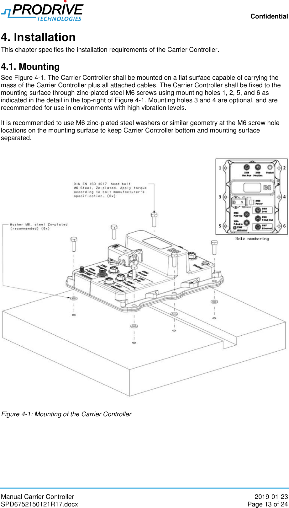
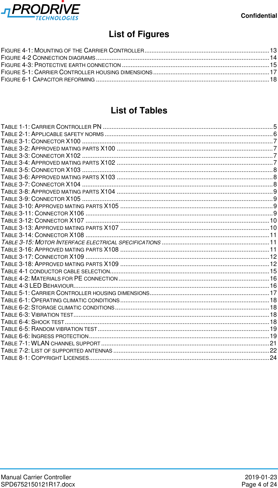
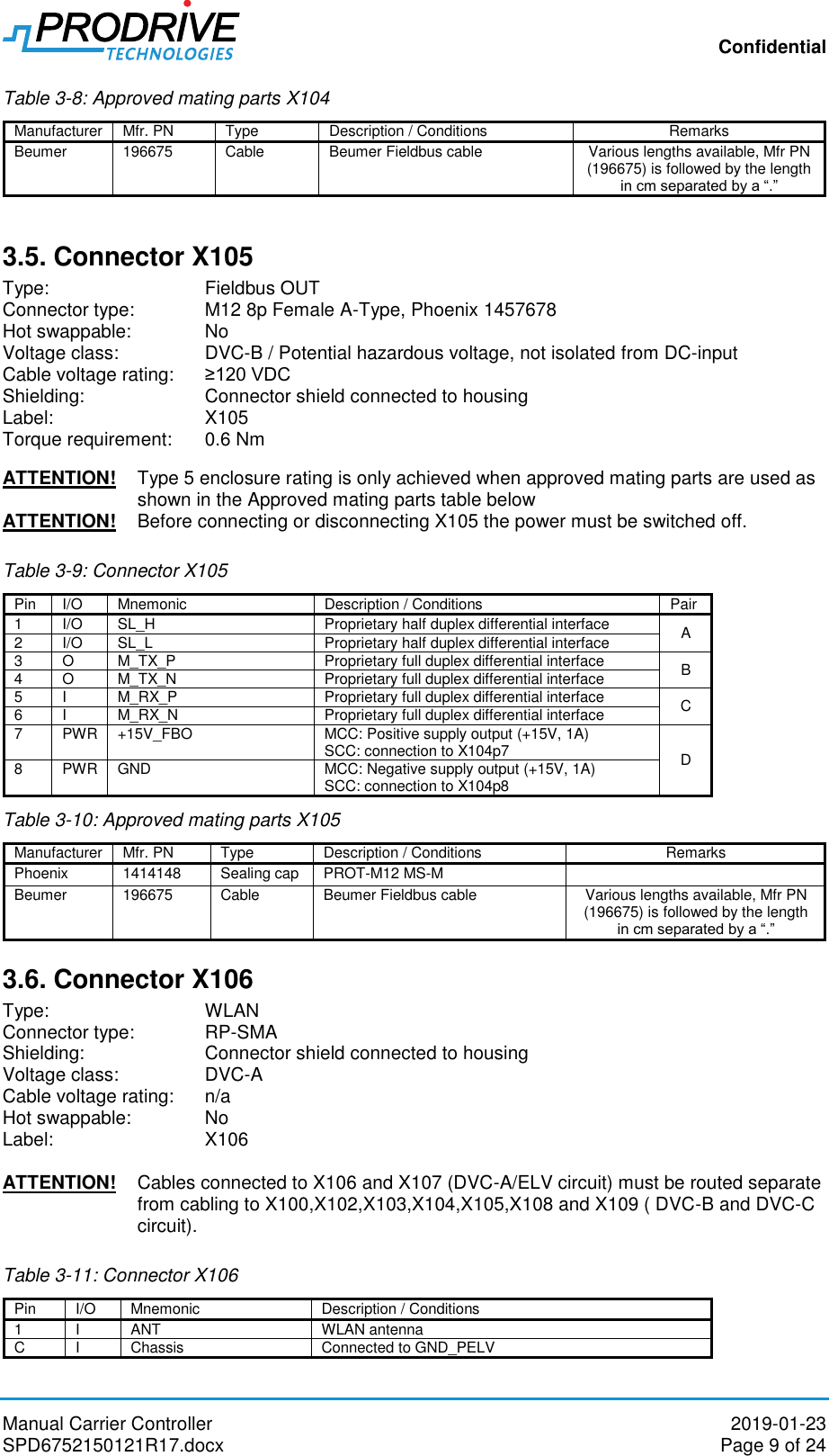
![Confidential Manual Carrier Controller 2019-01-23 SPD6752150121R17.docx Page 17 of 24 5. Mass and mechanical dimensions 5.1. Mass All Carrier Controller configurations have a mass of 1.4 ± 0.1 kg. 5.2. Mechanical dimensions Figure 5-1 and Table 5-1 show Carrier Controller housing dimensions. These dimensions are common to all Carrier Controller configurations. The Figure 5-1 shows the Master + IO + ETH configuration. (Depending on variant some connectors might not be available) Figure 5-1: Carrier Controller housing dimensions Table 5-1: Carrier Controller housing dimensions Symbol Description Typ Tolerance Unit Dfx Flange width 182 ± 1 [mm] Dfy Flange length 227 ± 1 [mm] Dx Housing width 141 ± 0.9 [mm] Dy Housing length 220 ± 1 [mm] Dz Housing height 68.5 ± 0.8 [mm] Mx Mounting hole distance in width direction 166 ± 1 [mm] My Mounting hole distance in length direction 90 ± 0.8 [mm]](https://usermanual.wiki/Prodrive-Technologies/CCMUL.User-manual/User-Guide-4161973-Page-17.png)
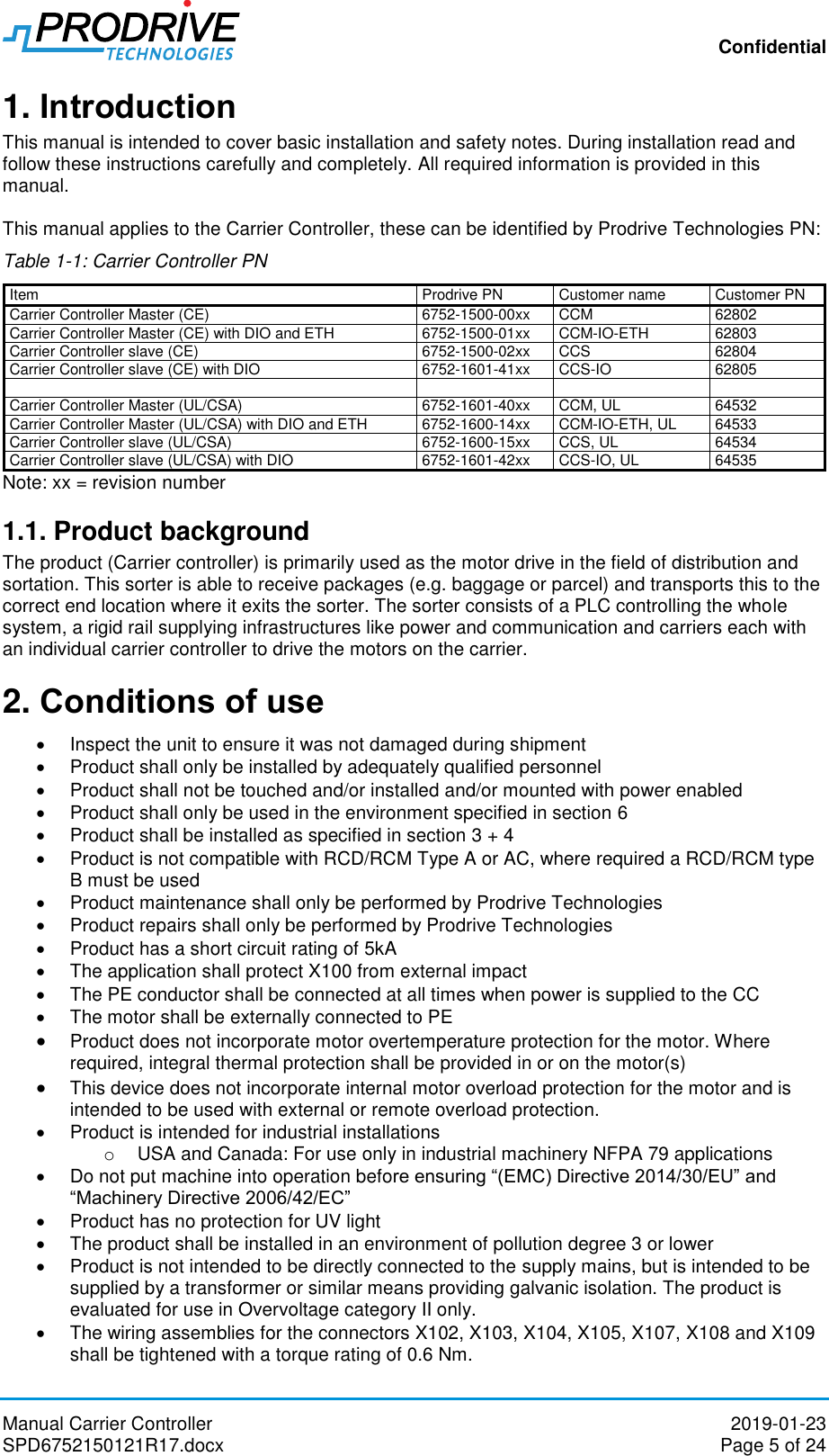
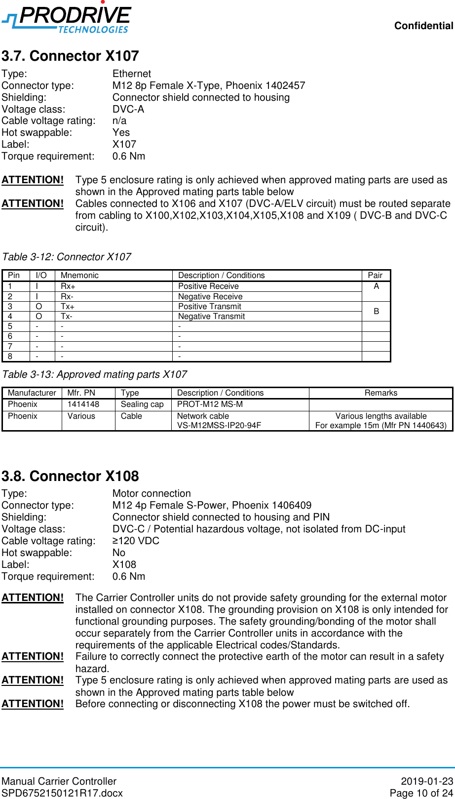
![Confidential Manual Carrier Controller 2019-01-23 SPD6752150121R17.docx Page 18 of 24 6. Environmental 6.1. Climatic Operating conditions Table 6-1: Operating climatic conditions Parameter Description Min Typ Max Unit Remarks TAMB Operating ambient temperature 0 22 45 [°C] RHAMB Operating humidity 0 95 [%] Relative humidity (no condensation) TAMB/dT Operating ambient temperature change rate -5 5 [°C/min] HALT Operating altitude AMSL 1000 [m] AMSL (Above Mean Sea Level) The product shall be installed in an environment of pollution degree 3 or lower. The product does not have protection for UV-light. 6.2. Storage conditions Table 6-2: Storage climatic conditions Parameter Description Min Typ1 Max Unit Remarks TST,AMB Storage ambient temperature -10 22 60 [°C] RHST,AMB Storage humidity 0 95 [%] Relative humidity (no condensation) TST,AMB/dT Storage ambient temperature change rate -5 5 [°C/min] HST,ALT Storage altitude AMSL 1000 [m] AMSL (Above Mean Sea Level) tSHELF 5 [yr] Shelf life > 12 months requires capacitor reforming, see Figure 6-1 Figure 6-1 Capacitor reforming 6.3. Shock and vibration Table 6-3: Vibration test Test procedure IEC 60068-2-6 Condition 1Hz to 500 Hz; 20m/s² amplitude; 20 frequency cycles in each axis Unpacked Number of axes 3 Table 6-4: Shock test Test procedure IEC 60068-2-27](https://usermanual.wiki/Prodrive-Technologies/CCMUL.User-manual/User-Guide-4161973-Page-18.png)
![Confidential Manual Carrier Controller 2019-01-23 SPD6752150121R17.docx Page 19 of 24 Condition Peak acceleration: 250m/s², Duration: 6ms, 1000 shocks in each axis, Half-sine Packed Number of axes 3 (positive and negative for each) Table 6-5: Random vibration test Test procedure IEC 60068-2-64:2008 Condition Acc. to table A.6, Categories 2a, 2b, 2c, Unpacked Number of axes 3 6.4. Ingres protection Table 6-6: Ingress protection Region Description Value Unit Remarks EU IP rating of carrier controller IP54 [-] Protection from dust and splashing water based on NEN-EN-IEC60529 IP rating is only achieved with connector cables and/or protection caps. USA/CA UL enclosure rating of carrier controller Type 5 [-] Enclosure rating is achieved with connector cables and/or protection caps. (Available from Phoenix 1414148). See the corresponding connector paragraph in chapter 3 for correct cables and/or protection caps. 6.5. Disposal This product should be treated as industrial waste when disposed. Dispose accordingly and comply with all local regulations.](https://usermanual.wiki/Prodrive-Technologies/CCMUL.User-manual/User-Guide-4161973-Page-19.png)
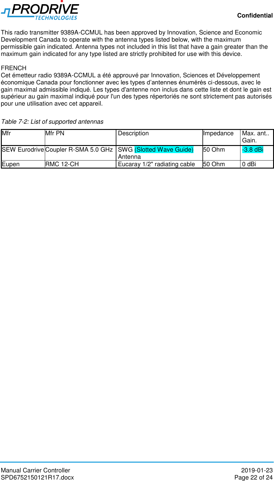
![Confidential Manual Carrier Controller 2019-01-23 SPD6752150121R17.docx Page 21 of 24 (2) l'appareil doit accepter tout brouillage radioélectrique subi, même si le brouillage est susceptible d'en compromettre le fonctionnement. Industrie Canada a autorisé cet émetteur radio à fonctionner avec les types d'antenne énumérés dans le mode d'emploi correspondant, avec le gain maximal admissible et l'impédance d'antenne requise pour chaque type d'antenne indiqué. Les types d'antenne non inclus dans cette liste, ayant un gain supérieur au gain maximal indiqué pour ce type, sont strictement interdits d'utilisation avec cet appareil. Selon les réglementations d'Industrie Canada, cet émetteur radio ne peut fonctionner qu'avec une antenne d'un type et d'un gain maximal (ou inférieur) approuvé pour l'émetteur par Industrie Canada. Pour réduire le risque de brouillage radioélectrique causé aux autres utilisateurs, le type d’antenne et son gain doivent être choisis de manière à ce que la puissance rayonnée isotrope équivalente (e.i.r.p.) ne soit pas supérieure à celle nécessaire au succès de la communication. Pour réduire le risque de brouillage radioélectrique causé aux autres utilisateurs, le type d’antenne et son gain doivent être choisis de manière à ce que la puissance rayonnée isotrope équivalente (par exemple) ne soit pas supérieure à celle autorisée pour une communication réussie. Que le dispositif pour la bande 5150-5250 MHz soit uniquement destiné à une utilisation en intérieur afin de réduire le risque de brouillage préjudiciable des systèmes de télécommunication par satellite mobiles dans le même canal. Les utilisateurs doivent également noter que les radars à haute puissance sont attribués en tant qu'utilisateurs principaux (c'est-à-dire qu'ils ont la priorité) de 5250-5350 MHz et 5650-5850 MHz et que ces radars peuvent causer des interférences et / ou des dommages aux dispositifs LE-LAN. Cet équipement est conforme aux limites d'exposition au rayonnement IC RSS-102 définies pour un environnement non contrôlé. Cet équipement doit être installé et utilisé à une distance minimale de 20 cm entre le radiateur et votre corps. 7.1. Channel support The master controller supports the channels shown in Table 7-1. Table 7-1: WLAN channel support Channel Center frequency [Mhz] Frequency range [Mhz] Bandwidth [Mhz] Band Channel limitations Remarks EU CA USA 36 5180 5170–5190 20 U-NII-1 Indoors Indoors - 40 5200 5190–5210 20 U-NII-1 Indoors Indoors - 44 5220 5210–5230 20 U-NII-1 Indoors Indoors - 48 5240 5230–5250 20 U-NII-1 Indoors Indoors - 52 5260 5250–5270 20 U-NII-2A Indoors DFS/TPC DFS DFS 56 5280 5270–5290 20 U-NII-2A Indoors DFS/TPC DFS DFS 60 5300 5290–5310 20 U-NII-2A Indoors DFS/TPC DFS DFS 64 5320 5310–5330 20 U-NII-2A Indoors DFS/TPC DFS DFS 100 5500 5490–5510 20 U-NII-2C DFS/TPC DFS DFS 104 5520 5510–5530 20 U-NII-2C DFS/TPC DFS DFS 108 5540 5530–5550 20 U-NII-2C DFS/TPC DFS DFS 112 5560 5550–5570 20 U-NII-2C DFS/TPC DFS DFS 116 5580 5570–5590 20 U-NII-2C DFS/TPC DFS DFS 132 5660 5650–5670 20 U-NII-2C DFS/TPC DFS DFS 136 5680 5670–5690 20 U-NII-2C DFS/TPC DFS DFS 140 5700 5690–5710 20 U-NII-2C DFS/TPC DFS DFS 7.2. List of supported antennas RSS-247 of Industry Canada (UL/CSA models) ENGLISH](https://usermanual.wiki/Prodrive-Technologies/CCMUL.User-manual/User-Guide-4161973-Page-21.png)