Prodrive Technologies CCMUL Carrier Controller User Manual
Prodrive Technologies B.V. Carrier Controller
Contents
- 1. User manual
- 2. Users Manual
User manual

Confidential
Template PN: 6001-1244-6904
Template date: 2016-07-26
Prodrive Technologies prodrive-technologies.com
PO Box 28030 Science Park Eindhoven 5501 T. +31 40 26 76 200
NL - 5602 JA Eindhoven NL - 5692 EM Son F. +31 40 26 76 201
Manual
of Carrier Controller
Prodrive Technologies B.V.
Reference: SPD6752150121R17.docx
Reference date: 2019-01-23
Author(s): Guido Beyer, Willem van Helmond
Status: Concept
Confidential
Manual Carrier Controller 2019-01-23
SPD6752150121R17.docx Page 2 of 24
The contents of this document are confidential information and intellectual property of Prodrive
Technologies. Nothing of this document may be used or duplicated or published without prior
written approval of Prodrive Technologies.
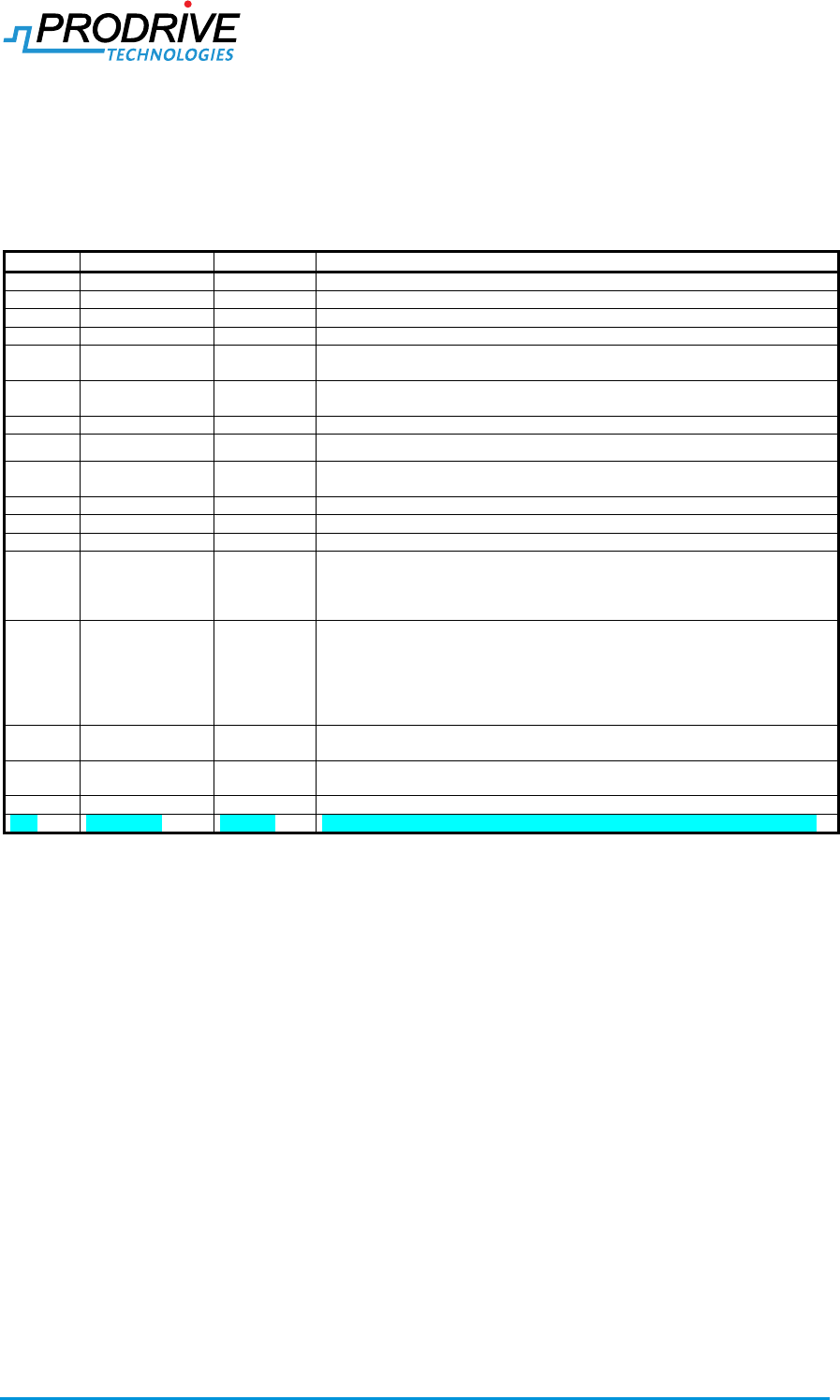
Document history
Rel.
Date
Status
Changes
R01
2016-12-12
Concept
Initial release manual for internal review.
R02
2016-12-14
Accepted
Updates after internal review, version released for CE approval
R03
2016-12-15
Accepted
Changed short circuit rating to 5kA, added IP54 note for connectors
R04
2016-12-21
Accepted
Removed RCD requirements, PE already ensures protection.
R05
2016-12-29
Accepted
Added LED, added capacitor reforming, added disposal section, added 3
conditions of use (first two and last two)
R06
2017-02-01
Accepted
Updated section 4.2 Mounting (removed horizontal mounting requirement,
added hole numbering). Corrected table 3-3
R07
2017-05-30
Accepted
Updated section 4.2 (removed contact washers, added flat washers)
R08
Concept
Various updates for UL certification.
R09
2017-10-27
Concept
Various updates for UL certification. (Added RCD requirement, external PE
connection to motor and different M12 protection caps),
R10
2018-02-07
Concept
Various updates for UL certification., WIFI -> WLAN, added WLAN channels
R11
2018-06-04
Concept
Various updates for UL certification
R12
2018-08-28
Concept
Update FCC modification notice, Update chapter 7 Radio
R13
18-10-2018
Concept
Added approved antenna list
Updated safety warnings
Updated mounting
Minor changes for safety
R14_rc1
R14_rc2
R14_rc3
R14_rc4
R14_rc5
06-11-2018
19-11-2018
21-11-2018
22-11-2018
22-11-2018
Concept
Updated safety items
Updated safety items
Updated safety items
Updated X108 connection to FE in Figure 4-2
Updated X104 (master) and X104+X105 (slave) circuit to basic insulation
and updated conditions of use.
R14
23-11-2018
Concept
R14 is release of R14_rc5 (see line above)
Used for CB report CER6752150130R01
R15
19-12-2018
Concept
Updated mounted instructions
Added remark to X100 cabling requirements
R16
22-01-2019
Concept
Minor adjustments for regulations
R17
23-01-2019
Concept
Corrected antenna gain, added clarification for SWG (Slotted Wave Guide)

Confidential
Manual Carrier Controller 2019-01-23
SPD6752150121R17.docx Page 3 of 24
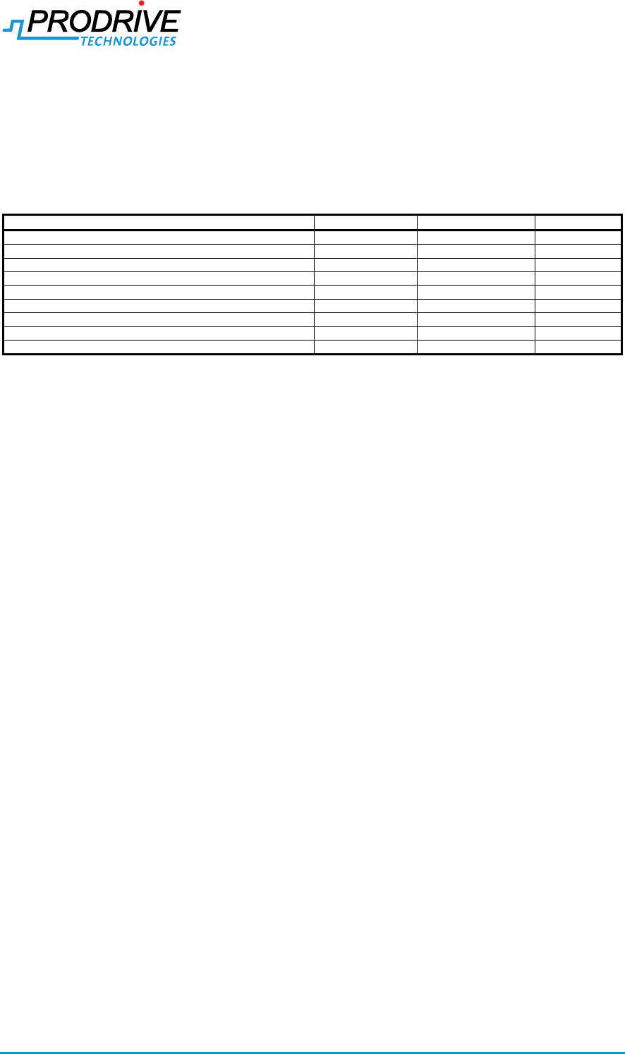
Contents
1. INTRODUCTION ............................................................................................................................. 5
1.1. PRODUCT BACKGROUND ............................................................................................................. 5
2. CONDITIONS OF USE ................................................................................................................... 5
2.1. GENERAL SAFETY WARNINGS ...................................................................................................... 6
3. RATINGS ........................................................................................................................................ 7
3.1. CONNECTOR X100 ..................................................................................................................... 7
3.2. CONNECTOR X102 ..................................................................................................................... 7
3.3. CONNECTOR X103 ..................................................................................................................... 8
3.4. CONNECTOR X104 ..................................................................................................................... 8
3.5. CONNECTOR X105 ..................................................................................................................... 9
3.6. CONNECTOR X106 ..................................................................................................................... 9
3.7. CONNECTOR X107 ................................................................................................................... 10
3.8. CONNECTOR X108 ................................................................................................................... 10
3.9. CONNECTOR X109 ................................................................................................................... 11
4. INSTALLATION ............................................................................................................................ 13
4.1. MOUNTING ............................................................................................................................... 13
4.2. CONNECTION DIAGRAMS ........................................................................................................... 14
4.3. CONDUCTOR SELECTION ........................................................................................................... 15
4.4. PROTECTIVE EARTH (PE) CONNECTION ...................................................................................... 15
4.5. LED ........................................................................................................................................ 16
5. MASS AND MECHANICAL DIMENSIONS .................................................................................. 17
5.1. MASS ....................................................................................................................................... 17
5.2. MECHANICAL DIMENSIONS ......................................................................................................... 17
6. ENVIRONMENTAL ....................................................................................................................... 18
6.1. CLIMATIC OPERATING CONDITIONS ............................................................................................ 18
6.2. STORAGE CONDITIONS .............................................................................................................. 18
6.3. SHOCK AND VIBRATION ............................................................................................................. 18
6.4. INGRES PROTECTION ................................................................................................................ 19
6.5. DISPOSAL................................................................................................................................. 19
7. RADIO ........................................................................................................................................... 20
7.1. CHANNEL SUPPORT .................................................................................................................. 21
7.2. LIST OF SUPPORTED ANTENNAS ................................................................................................. 21
8. CONTACT INFORMATION .......................................................................................................... 23
APPENDIX A. COPYRIGHT LICENSE ............................................................................................ 24

Confidential
Manual Carrier Controller 2019-01-23
SPD6752150121R17.docx Page 4 of 24
List of Figures
FIGURE 4-1: MOUNTING OF THE CARRIER CONTROLLER ........................................................................ 13
FIGURE 4-2 CONNECTION DIAGRAMS .................................................................................................... 14
FIGURE 4-3: PROTECTIVE EARTH CONNECTION ..................................................................................... 15
FIGURE 5-1: CARRIER CONTROLLER HOUSING DIMENSIONS ................................................................... 17
FIGURE 6-1 CAPACITOR REFORMING .................................................................................................... 18
List of Tables
TABLE 1-1: CARRIER CONTROLLER PN .................................................................................................. 5
TABLE 2-1: APPLICABLE SAFETY NORMS ................................................................................................. 6
TABLE 3-1: CONNECTOR X100 .............................................................................................................. 7
TABLE 3-2: APPROVED MATING PARTS X100 .......................................................................................... 7
TABLE 3-3: CONNECTOR X102 .............................................................................................................. 7
TABLE 3-4: APPROVED MATING PARTS X102 .......................................................................................... 7
TABLE 3-5: CONNECTOR X103 .............................................................................................................. 8
TABLE 3-6: APPROVED MATING PARTS X103 .......................................................................................... 8
TABLE 3-7: CONNECTOR X104 .............................................................................................................. 8
TABLE 3-8: APPROVED MATING PARTS X104 .......................................................................................... 9
TABLE 3-9: CONNECTOR X105 .............................................................................................................. 9
TABLE 3-10: APPROVED MATING PARTS X105 ........................................................................................ 9
TABLE 3-11: CONNECTOR X106 ............................................................................................................ 9
TABLE 3-12: CONNECTOR X107 .......................................................................................................... 10
TABLE 3-13: APPROVED MATING PARTS X107 ...................................................................................... 10
TABLE 3-14: CONNECTOR X108 .......................................................................................................... 11
TABLE 3-15: MOTOR INTERFACE ELECTRICAL SPECIFICATIONS .............................................................. 11
TABLE 3-16: APPROVED MATING PARTS X108 ...................................................................................... 11
TABLE 3-17: CONNECTOR X109 .......................................................................................................... 12
TABLE 3-18: APPROVED MATING PARTS X109 ...................................................................................... 12
TABLE 4-1 CONDUCTOR CABLE SELECTION............................................................................................ 15
TABLE 4-2: MATERIALS FOR PE CONNECTION ....................................................................................... 16
TABLE 4-3 LED BEHAVIOUR................................................................................................................. 16
TABLE 5-1: CARRIER CONTROLLER HOUSING DIMENSIONS ..................................................................... 17
TABLE 6-1: OPERATING CLIMATIC CONDITIONS ...................................................................................... 18
TABLE 6-2: STORAGE CLIMATIC CONDITIONS ......................................................................................... 18
TABLE 6-3: VIBRATION TEST ................................................................................................................. 18
TABLE 6-4: SHOCK TEST ...................................................................................................................... 18
TABLE 6-5: RANDOM VIBRATION TEST ................................................................................................... 19
TABLE 6-6: INGRESS PROTECTION ........................................................................................................ 19
TABLE 7-1: WLAN CHANNEL SUPPORT ................................................................................................. 21
TABLE 7-2: LIST OF SUPPORTED ANTENNAS .......................................................................................... 22
TABLE 8-1: COPYRIGHT LICENSES ........................................................................................................ 24
Confidential
Manual Carrier Controller 2019-01-23
SPD6752150121R17.docx Page 5 of 24
1. Introduction
This manual is intended to cover basic installation and safety notes. During installation read and
follow these instructions carefully and completely. All required information is provided in this
manual.
This manual applies to the Carrier Controller, these can be identified by Prodrive Technologies PN:
Table 1-1: Carrier Controller PN
Item
Prodrive PN
Customer name
Customer PN
Carrier Controller Master (CE)
6752-1500-00xx
CCM
62802
Carrier Controller Master (CE) with DIO and ETH
6752-1500-01xx
CCM-IO-ETH
62803
Carrier Controller slave (CE)
6752-1500-02xx
CCS
62804
Carrier Controller slave (CE) with DIO
6752-1601-41xx
CCS-IO
62805
Carrier Controller Master (UL/CSA)
6752-1601-40xx
CCM, UL
64532
Carrier Controller Master (UL/CSA) with DIO and ETH
6752-1600-14xx
CCM-IO-ETH, UL
64533
Carrier Controller slave (UL/CSA)
6752-1600-15xx
CCS, UL
64534
Carrier Controller slave (UL/CSA) with DIO
6752-1601-42xx
CCS-IO, UL
64535
Note: xx = revision number
1.1. Product background
The product (Carrier controller) is primarily used as the motor drive in the field of distribution and
sortation. This sorter is able to receive packages (e.g. baggage or parcel) and transports this to the
correct end location where it exits the sorter. The sorter consists of a PLC controlling the whole
system, a rigid rail supplying infrastructures like power and communication and carriers each with
an individual carrier controller to drive the motors on the carrier.
2. Conditions of use
Inspect the unit to ensure it was not damaged during shipment
Product shall only be installed by adequately qualified personnel
Product shall not be touched and/or installed and/or mounted with power enabled
Product shall only be used in the environment specified in section 6
Product shall be installed as specified in section 3 + 4
Product is not compatible with RCD/RCM Type A or AC, where required a RCD/RCM type
B must be used
Product maintenance shall only be performed by Prodrive Technologies
Product repairs shall only be performed by Prodrive Technologies
Product has a short circuit rating of 5kA
The application shall protect X100 from external impact
The PE conductor shall be connected at all times when power is supplied to the CC
The motor shall be externally connected to PE
Product does not incorporate motor overtemperature protection for the motor. Where
required, integral thermal protection shall be provided in or on the motor(s)
This device does not incorporate internal motor overload protection for the motor and is
intended to be used with external or remote overload protection.
Product is intended for industrial installations
o USA and Canada: For use only in industrial machinery NFPA 79 applications
Do not put machine into operation before ensuring “(EMC) Directive 2014/30/EU” and
“Machinery Directive 2006/42/EC”
Product has no protection for UV light
The product shall be installed in an environment of pollution degree 3 or lower
Product is not intended to be directly connected to the supply mains, but is intended to be
supplied by a transformer or similar means providing galvanic isolation. The product is
evaluated for use in Overvoltage category II only.
The wiring assemblies for the connectors X102, X103, X104, X105, X107, X108 and X109
shall be tightened with a torque rating of 0.6 Nm.
Confidential
Manual Carrier Controller 2019-01-23
SPD6752150121R17.docx Page 6 of 24
In case, the cable assemblies for X102, X103, X104, X105, X107, X108 and/or X109 are
not installed on the product, each of the unused connector shall be closed with a sealing
cap, PROT-M12 MS-M1414148 manufactured by Phoenix. These sealing caps shall also to
be tightened with 0.6 Nm.
The product is powered by a 100V DC power supply either isolated or non-isolated. The
earthing system must be evaluated on system level for safe operation of the product.
2.1. General safety warnings
CAUTION!
During the UL evaluation, only Risk of Electrical Shock and Risk of Fire aspects
were investigated. Functional Safety aspects were not evaluated
CAUTION!
Suitable For Use On A Circuit Capable Of Delivering Not More Than 5000 rms
Symmetrical Amperes, 100 Volts DC Maximum
CAUTION!
Integral solid state short circuit protection does not provide branch circuit
protection. Branch circuit protection must be provided in accordance with the
National Electrical Code and any additional local codes
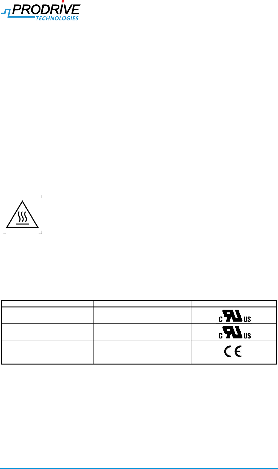
CAUTION!
High temperature on electronics housing, Risk of burns
NOTICE:
Changes or modifications made to this equipment not expressly approved by
Prodrive Technologies B.V. may void the FCC authorization to operate this
equipment.
Table 2-1: Applicable safety norms
Norm
Description
Label1
CSA-22.2 no. 274-17
Adjustable speed drives (Canada)
UL 61800-5-1
Power conversion equipment (US)
IEC-EN 61800-5-1
Adjustable Speed Electrical Power Drive
Systems - Safety Requirements -
Electrical, Thermal and Energy (Europe)
Note[1]: Depending on model, only applicable if logo is present on product label
Confidential
Manual Carrier Controller 2019-01-23
SPD6752150121R17.docx Page 7 of 24
3. Ratings
3.1. Connector X100
Type: Power input
Connector type: Harting Han 3A: 09200030827 + 09120023052 + 09320006108
Shielding: None
Voltage class: DVC-B / Potential hazardous voltage, not isolated from DC-input
Cable voltage rating: ≥120 VDC
Over voltage category: OVC II with galvanic separation from mains
Hot swappable: No
Label: X100
ATTENTION! Type 5 enclosure rating is only achieved when approved mating parts are used as
shown in the Approved mating parts table below
ATTENTION! Before connecting or disconnecting X100 the power must be switched off.
Table 3-1: Connector X100
Pin
I/O
Mnemonic
Description / Conditions
1
PWR
DC_IN+
Positive power input / 100V @ 9Arms
2
PWR
DC_IN- (GND)
Negative power input / 100V @ 9Arms
PE
nc
n/a
Not connected
Table 3-2: Approved mating parts X100
Manufacturer
Mfr. PN
Type
Description / Conditions
Remarks
Beumer
1204660514
Cable
Power cable
Cable assembly build identical to
1204660514 with the only exception
of the cable lengths is also
acceptable
3.2. Connector X102
Type: Pick-up interface
Connector type: M12 4p Female D-Type, Phoenix 1411936
Shielding: Connector shield connected to housing
Voltage class: DVC-B / Potential hazardous voltage, not isolated from DC-input
Cable voltage rating: ≥120 VDC
Hot swappable: No
Label: X102
Torque requirement: 0.6 Nm
ATTENTION! Type 5 enclosure rating is only achieved when approved mating parts are used as
shown in the Approved mating parts table below
ATTENTION! Before connecting or disconnecting X102 the power must be switched off.
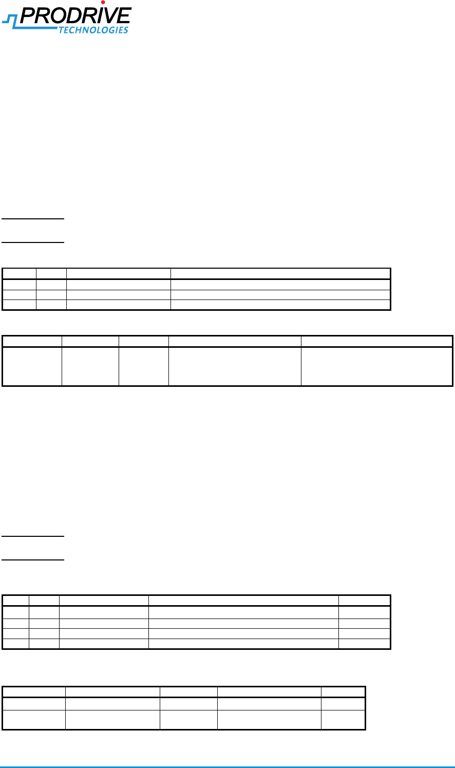
Table 3-3: Connector X102
Pin
I/O
Mnemonic
Description / Conditions
Pair
1
I/O
PU_P
Proprietary half duplex differential interface
A
2
I/O
PU_N
Proprietary half duplex differential interface
A
3
PWR
+15V_PU
Positive supply (+15V, 50mA)
B
4
PWR
GND
Negative supply (+15V, 50mA)
B
Table 3-4: Approved mating parts X102
Manufacturer
Mfr. PN
Type
Description / Conditions
Remarks
Phoenix
1414148
Sealing cap
PROT-M12 MS-M
SEW
18191460
Cable
Signalkabel M04D-C4-
CW45
Confidential
Manual Carrier Controller 2019-01-23
SPD6752150121R17.docx Page 8 of 24
3.3. Connector X103
Type: IO
Connector type: M12 8p Female A-Type, Phoenix 1457678
Shielding: Connector shield connected to housing
Voltage class: DVC-B / Potential hazardous voltage, not isolated from DC-input
Cable voltage rating: ≥120 VDC
Hot swappable: No
Label: X103
Torque requirement: 0.6 Nm
ATTENTION! Type 5 enclosure rating is only achieved when approved mating parts are used as
shown in the Approved mating parts table below
ATTENTION! Before connecting or disconnecting X103 the power must be switched off.
Table 3-5: Connector X103
Pin
I/O
Mnemonic
Description / Conditions
1
O
HV-OUT_0
Switchable output 0 (24V, 200mA)
2
PWR
GND
GND
3
I
HV-IN_0
Input 0 (24V)
4
PWR
GND
GND
5
O
HV-OUT_1
Switchable output 1 (24V, 200mA)
6
PWR
GND
GND
7
I
HV-IN_1
Input 1 (24V)
8
PWR
GND
GND
Table 3-6: Approved mating parts X103
Manufacturer
Mfr. PN
Type
Description / Conditions
Remarks
Phoenix
1414148
Sealing cap
PROT-M12 MS-M
Phoenix
1522817
Cable
Sensor/actuator cable - SAC-8P-M12MR/ 1,5-PUR SH
3.4. Connector X104
Type: Fieldbus IN
Connector type: M12 8p Male A-Type, Phoenix 1457555
Shielding: Connector shield connected to housing
Voltage class: DVC-B / Potential hazardous voltage, not isolated from DC-input
Cable voltage rating: ≥120 VDC
Hot swappable: No
Label: X104
Torque requirement: 0.6 Nm
ATTENTION! Type 5 enclosure rating is only achieved when approved mating parts are used as
shown in the Approved mating parts table below
ATTENTION! Before connecting or disconnecting X104 the power must be switched off.
Table 3-7: Connector X104
Pin
I/O
Mnemonic
Description / Conditions
Pair
1
I/O
SL_H
Proprietary half duplex differential interface
A
2
I/O
SL_L
Proprietary half duplex differential interface
3
I
M_RX_P
Proprietary full duplex differential interface
B
4
I
M_RX_N
Proprietary full duplex differential interface
5
O
M_TX_P
Proprietary full duplex differential interface
C
6
O
M_TX_N
Proprietary full duplex differential interface
7
PWR
+15V_FBI
Positive supply input (+15V_FBI)
D
8
PWR
GND_FBI
Negative supply input (+15V_FBI)
Confidential
Manual Carrier Controller 2019-01-23
SPD6752150121R17.docx Page 9 of 24
Table 3-8: Approved mating parts X104
Manufacturer
Mfr. PN
Type
Description / Conditions
Remarks
Beumer
196675
Cable
Beumer Fieldbus cable
Various lengths available, Mfr PN
(196675) is followed by the length
in cm separated by a “.”
3.5. Connector X105
Type: Fieldbus OUT
Connector type: M12 8p Female A-Type, Phoenix 1457678
Hot swappable: No
Voltage class: DVC-B / Potential hazardous voltage, not isolated from DC-input
Cable voltage rating: ≥120 VDC
Shielding: Connector shield connected to housing
Label: X105
Torque requirement: 0.6 Nm
ATTENTION! Type 5 enclosure rating is only achieved when approved mating parts are used as
shown in the Approved mating parts table below
ATTENTION! Before connecting or disconnecting X105 the power must be switched off.
Table 3-9: Connector X105
Pin
I/O
Mnemonic
Description / Conditions
Pair
1
I/O
SL_H
Proprietary half duplex differential interface
A
2
I/O
SL_L
Proprietary half duplex differential interface
3
O
M_TX_P
Proprietary full duplex differential interface
B
4
O
M_TX_N
Proprietary full duplex differential interface
5
I
M_RX_P
Proprietary full duplex differential interface
C
6
I
M_RX_N
Proprietary full duplex differential interface
7
PWR
+15V_FBO
MCC: Positive supply output (+15V, 1A)
SCC: connection to X104p7
D
8
PWR
GND
MCC: Negative supply output (+15V, 1A)
SCC: connection to X104p8
Table 3-10: Approved mating parts X105
Manufacturer
Mfr. PN
Type
Description / Conditions
Remarks
Phoenix
1414148
Sealing cap
PROT-M12 MS-M
Beumer
196675
Cable
Beumer Fieldbus cable
Various lengths available, Mfr PN
(196675) is followed by the length
in cm separated by a “.”
3.6. Connector X106
Type: WLAN
Connector type: RP-SMA
Shielding: Connector shield connected to housing
Voltage class: DVC-A
Cable voltage rating: n/a
Hot swappable: No
Label: X106
ATTENTION! Cables connected to X106 and X107 (DVC-A/ELV circuit) must be routed separate
from cabling to X100,X102,X103,X104,X105,X108 and X109 ( DVC-B and DVC-C
circuit).
Table 3-11: Connector X106
Pin
I/O
Mnemonic
Description / Conditions
1
I
ANT
WLAN antenna
C
I
Chassis
Connected to GND_PELV
Confidential
Manual Carrier Controller 2019-01-23
SPD6752150121R17.docx Page 10 of 24
3.7. Connector X107
Type: Ethernet
Connector type: M12 8p Female X-Type, Phoenix 1402457
Shielding: Connector shield connected to housing
Voltage class: DVC-A
Cable voltage rating: n/a
Hot swappable: Yes
Label: X107
Torque requirement: 0.6 Nm
ATTENTION! Type 5 enclosure rating is only achieved when approved mating parts are used as
shown in the Approved mating parts table below
ATTENTION! Cables connected to X106 and X107 (DVC-A/ELV circuit) must be routed separate
from cabling to X100,X102,X103,X104,X105,X108 and X109 ( DVC-B and DVC-C
circuit).
Table 3-12: Connector X107
Pin
I/O
Mnemonic
Description / Conditions
Pair
1
I
Rx+
Positive Receive
A
2
I
Rx-
Negative Receive
3
O
Tx+
Positive Transmit
B
4
O
Tx-
Negative Transmit
5
-
-
-
6
-
-
-
7
-
-
-
8
-
-
-
Table 3-13: Approved mating parts X107
3.8. Connector X108
Type: Motor connection
Connector type: M12 4p Female S-Power, Phoenix 1406409
Shielding: Connector shield connected to housing and PIN
Voltage class: DVC-C / Potential hazardous voltage, not isolated from DC-input
Cable voltage rating: ≥120 VDC
Hot swappable: No
Label: X108
Torque requirement: 0.6 Nm
ATTENTION! The Carrier Controller units do not provide safety grounding for the external motor
installed on connector X108. The grounding provision on X108 is only intended for
functional grounding purposes. The safety grounding/bonding of the motor shall
occur separately from the Carrier Controller units in accordance with the
requirements of the applicable Electrical codes/Standards.
ATTENTION! Failure to correctly connect the protective earth of the motor can result in a safety
hazard.
ATTENTION! Type 5 enclosure rating is only achieved when approved mating parts are used as
shown in the Approved mating parts table below
ATTENTION! Before connecting or disconnecting X108 the power must be switched off.
Manufacturer
Mfr. PN
Type
Description / Conditions
Remarks
Phoenix
1414148
Sealing cap
PROT-M12 MS-M
Phoenix
Various
Cable
Network cable
VS-M12MSS-IP20-94F
Various lengths available
For example 15m (Mfr PN 1440643)
Confidential
Manual Carrier Controller 2019-01-23
SPD6752150121R17.docx Page 11 of 24
Table 3-14: Connector X108
Pin
I/O
Mnemonic
Description / Conditions
1
O
L1
Motor phase 1 output
2
O
L2
Motor phase 2 output
3
O
L3
Motor phase 3 output
4
FE
FE
FE connection
-
S
Shield
Shield for cable
Motor output specification:
3 phases BLDC
Protected against short circuit
o No safety hazard
o DC-Power-Bus is not shorted
Functional protections
o All protections disable end-stage if not mentioned otherwise
o Instantaneous current (IPHASE,OCP)
o RMS current (IPHASE,RMS)
o DC-Power-Bus voltage
Below VDC-POWER-BUS,NOSTART no movement is started
Under voltage of DC-Power-Bus below VDC-POWER-BUS,UVP
Over voltage of DC-Power-Bus above VDC-POWER-BUS,OVP
o Temperature
Over temperature of end-stage
Table 3-15: Motor Interface electrical specifications
Item
Comments
Min
Typ
Max
Unit
VDC-POWER-BUS,OVP
Over voltage protection of DC-Power-Bus
120
[V]
VDC-POWER-BUS,UVP
Under voltage protection of DC-Power-Bus
30
[V]
VDC-POWER-BUS
Voltage of DC-Power-Bus
30
110
[V]
VDC-POWER-BUS,NOSTART1
Voltage of DC-Power-Bus below which no
movement is started
85
[V]
IPHASE,RMS
RMS phase current
6.5
[ARMS]
IPHASE,LIMIT
Adjustable phase peak current limit
10
45
[A]
IPHASE,OCP
Over current protection
45
[A]
LMOTOR,PH-PH
Inductance per motor phase to phase
0.3
10
[mH]
RMOTOR,PH-PH
Resistance per motor phase to phase
0.25
[Ω]
fMOTOR,ELE
Electrical motor frequency
400
[Hz]
fSW
Switching frequency
20
[kHz]
δ
Duty-cycle limit during operation
2
96
[%]
Table 3-16: Approved mating parts X108
Manufacturer
Mfr. PN
Type
Description / Conditions
Remarks
Phoenix
1414148
Sealing cap
PROT-M12 MS-M
Finecables
BYD6.646.003
Motor
Motor cable
3.9. Connector X109
Type: Hall sensor connection
Connector type: M12 5p Female A-Type, Phoenix 1457649
Shielding: Connector shield connected to housing
Voltage class: DVC-B / Potential hazardous voltage, not isolated from DC-input
Cable voltage rating: ≥120 VDC
Hot swappable: No
Label: X109
Torque requirement: 0.6 Nm
Confidential
Manual Carrier Controller 2019-01-23
SPD6752150121R17.docx Page 12 of 24
ATTENTION! Type 5 enclosure rating is only achieved when approved mating parts are used as
shown in the Approved mating parts table below
ATTENTION! Before connecting or disconnecting X109 the power must be switched off.
Motor hall sensor specification:
- 3 phase hall sensor interface
- +15V supply for hall sensors
- Hall sensor fault detection
- Resettable fuse
Table 3-17: Connector X109
Pin
I/O
Mnemonic
Description / Conditions
1
I
HALL_1
Hall phase 1 input (+15V)
2
I
HALL_2
Hall phase 2 input (+15V)
3
I
HALL_3
Hall phase 3 input (+15V)
4
PWR
VP_HALL+
Positive supply (+15V, 25mA)
5
PWR
GND
Negative hall supply
-
S
Shield
Shield for cable
Table 3-18: Approved mating parts X109
Manufacturer
Mfr. PN
Type
Description / Conditions
Remarks
Phoenix
1414148
Sealing cap
PROT-M12 MS-M
Finecables
BYD6.646.004
Motor
Hall sensor cable
Confidential
Manual Carrier Controller 2019-01-23
SPD6752150121R17.docx Page 13 of 24
4. Installation
This chapter specifies the installation requirements of the Carrier Controller.
4.1. Mounting
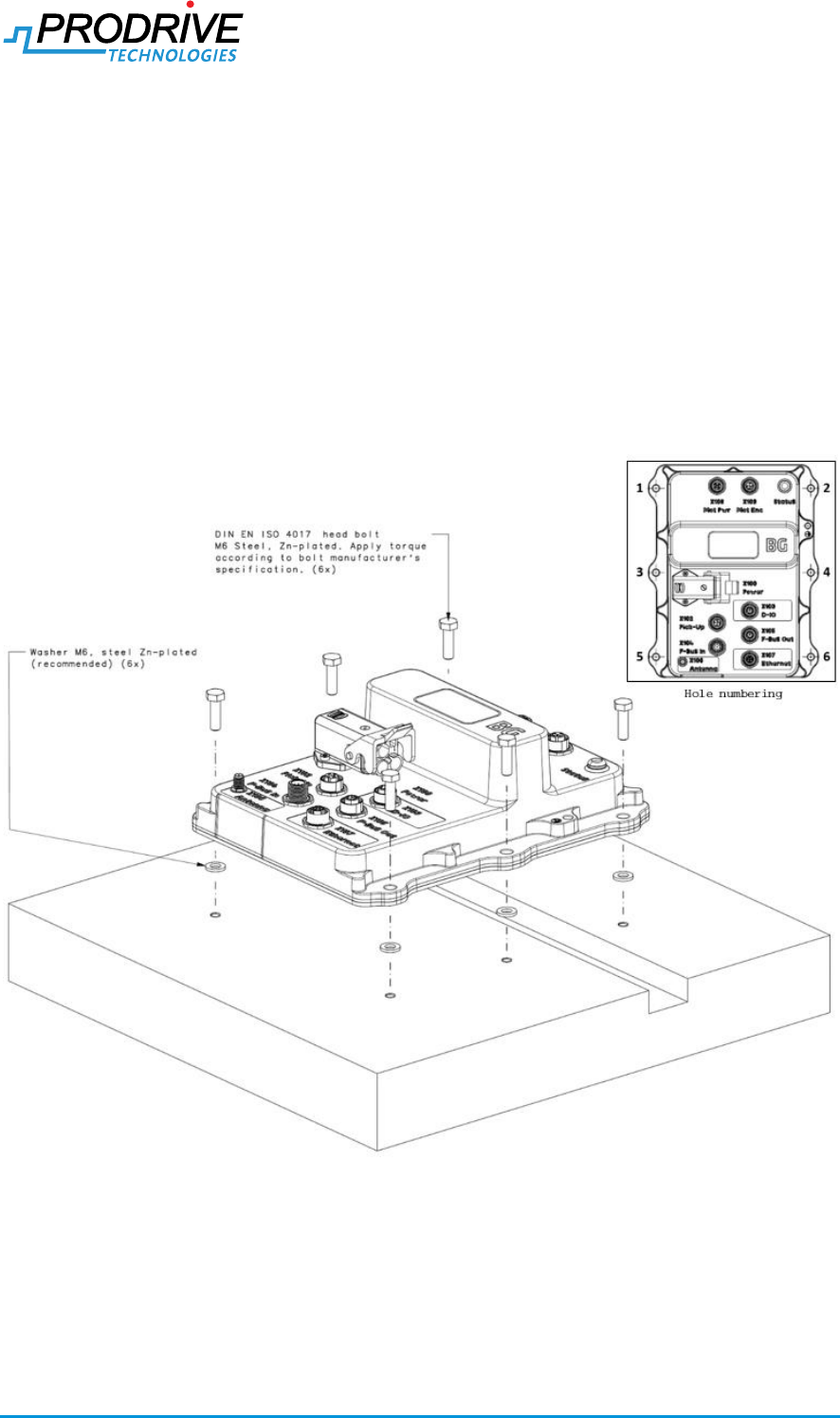
See Figure 4-1. The Carrier Controller shall be mounted on a flat surface capable of carrying the
mass of the Carrier Controller plus all attached cables. The Carrier Controller shall be fixed to the
mounting surface through zinc-plated steel M6 screws using mounting holes 1, 2, 5, and 6 as
indicated in the detail in the top-right of Figure 4-1. Mounting holes 3 and 4 are optional, and are
recommended for use in environments with high vibration levels.
It is recommended to use M6 zinc-plated steel washers or similar geometry at the M6 screw hole
locations on the mounting surface to keep Carrier Controller bottom and mounting surface
separated.
Figure 4-1: Mounting of the Carrier Controller
Confidential
Manual Carrier Controller 2019-01-23
SPD6752150121R17.docx Page 14 of 24
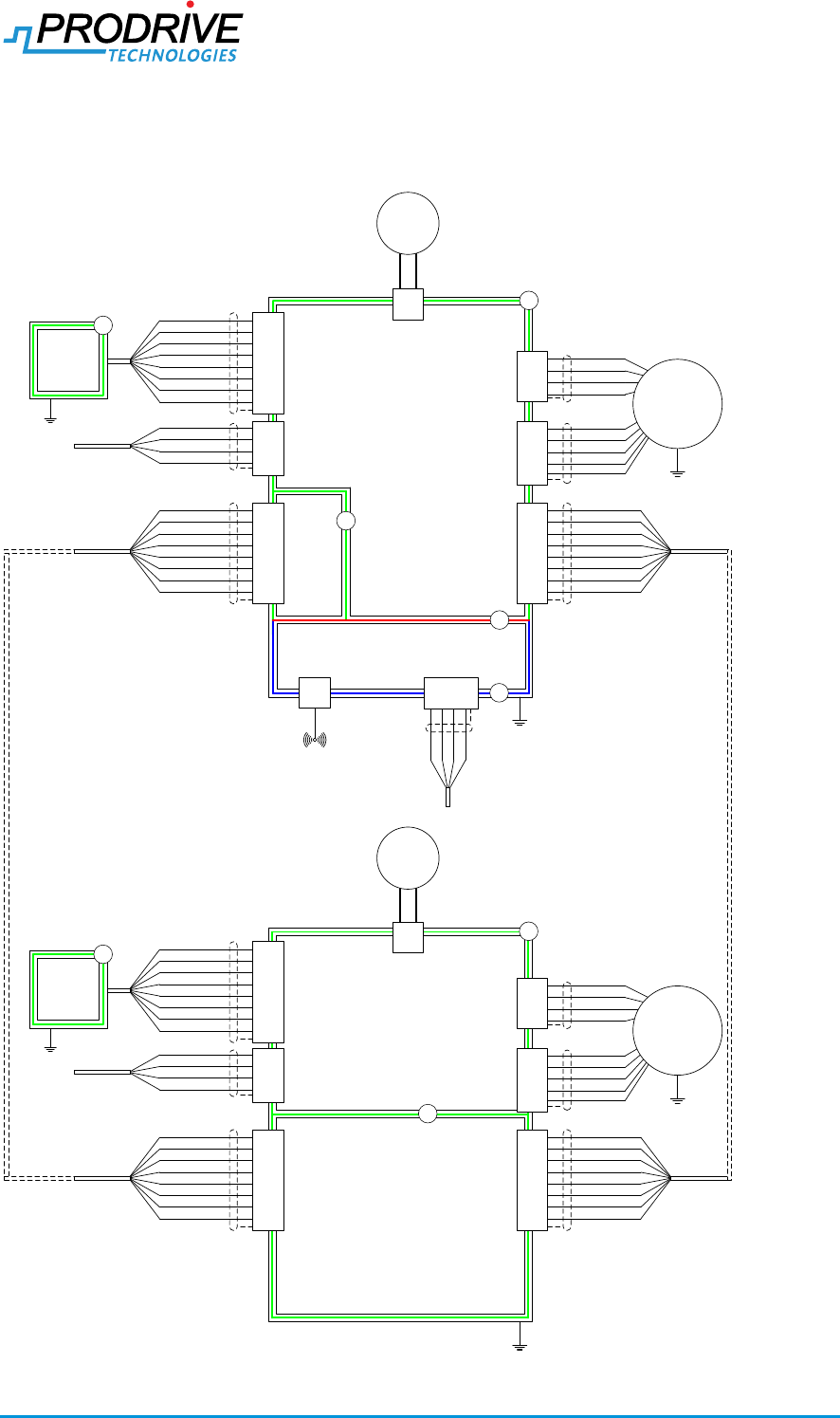
4.2. Connection diagrams
Wiring diagram of the product is described in Figure 4-2, the product can be connected in a chain
starting and ending with a master controller (can be the same master). In between up to 60 slaves
controller can be connected to the slave bus.
Protective Earth (PE)
Ethernet
PELV
(DVC A)
F
HV1
(DVC B)
HV2
(DVC B)
B
X108
L2
Shield
L1
L3
FE
Shield
HALL_1
HALL_2
HALL_3
VP_HALL
GND
X105
M
X100
DC_IN+DC_IN-
SUP
Shield
C1-IO_H
C1-IO_L
C1-IO_RX_P
C1-IO_RX_N
C1-IO_TX_P
+15V_MFB
GND_MFB
OC1-IO_TX_N
Fieldbus-Out
X104
Shield
C1-IO_H
C1-IO_L
C1-IO_RX_P
C1-IO_RX_N
C1-IO_TX_P
+15V_MFB
GND_MFB
OC1-IO_TX_N
Fieldbus-In
HV 1
(DVC B)
HV 2
(DVC B)
Shield
PU-IO_P
PU-IO_N
+15V_PU
GND
Pickup
Protective Earth (PE)
X102
B
B
R
X107X106
WiFi
Antenna
RX+
RX-
TX+
TX-
Protective Earth (PE)
X108
L2
Shield
L1
L3
FE
Shield
HALL_1
HALL_2
HALL_3
VP_HALL
GND
X104
M
X100
DC_IN+DC_IN-
SUP
Shield
C1-IO_H
C1-IO_L
C1-IO_RX_P
C1-IO_RX_N
C1-IO_TX_P
+15V_MFI
GND_MFI
OC1-IO_TX_N Fieldbus-In
X105
C1-IO_H
C1-IO_L
C1-IO_RX_P
C1-IO_RX_N
C1-IO_TX_P
+15V_MFB
GND_MFB
OC1-IO_TX_N
Fieldbus-Out
Shield
PU-IO_P
PU-IO_N
+15V_PU
GND
Pickup
X102
HV 1
(DVC B)
I/O
Module
B
X103
PE
B
Protective Earth (PE)
Shield
HV-OUT_0
GND
HV-IN_0
GND
HV-OUT_1
HV-IN_1
GND
GND
Shield
HV 1
(DVC B)
I/O
Module
B
X103
PE
HV-OUT_0
GND
HV-IN_0
GND
HV-OUT_1
HV-IN_1
GND
GND
Shield
Figure 4-2 Connection diagrams
Confidential
Manual Carrier Controller 2019-01-23
SPD6752150121R17.docx Page 15 of 24
4.3. Conductor selection
Cables used for power connectors need to comply with the requirements in Table 4-1.
Table 4-1 conductor cable selection
Parameter
Requirement
Remark
Voltage rating
Minimum 120V
DC input wire cross section
6.0mm2
Protective Earth conductor cross
section
6.0mm2
Motor output wire cross section
At least 1.5mm2
Motor earth bonding conductor cross
section.
At least 6.0mm2
Product does not provide earth bonding
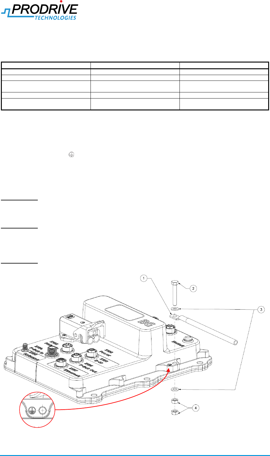
4.4. Protective earth (PE) connection
Prior to installing any other cable, the Carrier Controller must be connected to earth by fixing an
earthing wire with cable lug (1) using a screw (2), two flat washers (3), and two nuts (4) to the hole
marked with the PE logo as indicated in Figure 4-3 and Table 4-2.
The earthing wire must have a cross-sectional area of at least 6 mm2 if copper is used as a
conductor. Otherwise, the cross-sectional area of the earthing wire shall be such that its
conductance is equivalent to that of a 6 mm2 copper wire, and shall not be less than 4 mm2.
ATTENTION! It is not allowed to use the hole marked with the PE logo, screw (2), rings (3) and
nuts (4) for any other purpose than mechanically and electrically connecting the earthing wire to the
Carrier Controller.
ATTENTION! Enclosure and fasteners of the Carrier Controller are aluminum and zinc-plated steel,
respectively. Earthing wire, cable lug, earthing connector and fastener materials must be chosen
such that the current-carrying capacity of the protective earth connection will not be impaired by
electrochemical corrosion.
ATTENTION! Failure to correctly connect the protective earth can result in a safety hazard.
Figure 4-3: Protective earth connection
Confidential
Manual Carrier Controller 2019-01-23
SPD6752150121R17.docx Page 16 of 24
Table 4-2: Materials for PE connection
#
Component
Description
Material
2
Screw
M5x25
Zinc-plated steel
3
Flat washer
M5
3
Nut
M5
4.5. LED
Table 4-3 shows which condition leads to which LED behaviour. Following properties apply:
- The LED behaviour is determined by the priority mentioned in Table 4-3, where a lower
number denotes a higher priority. All conditions with priority 3 are mutually exclusive.
Table 4-3 LED Behaviour
Prio.
Condition
Behaviour
1
Can bus in error-passive or bus-off state
Magenta (red+blue)
2
State WaitCanAddress
Blue
3
Loader mode
Blue blinking
3
Application mode, in state Error
Red
3
Application mode, in state Reset
Red blinking
3
Application mode, in state Setup
Yellow (Green+Red)
3
Application mode, in state Startup, Moving, Settling or FindHome
Green
3
Application mode, in state Off
Green blinking
Confidential
Manual Carrier Controller 2019-01-23
SPD6752150121R17.docx Page 17 of 24
5. Mass and mechanical dimensions
5.1. Mass
All Carrier Controller configurations have a mass of 1.4 ± 0.1 kg.
5.2. Mechanical dimensions
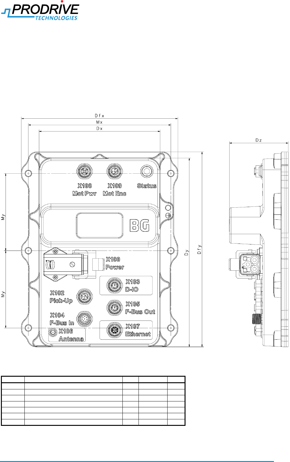
Figure 5-1 and Table 5-1 show Carrier Controller housing dimensions. These dimensions are
common to all Carrier Controller configurations. The Figure 5-1 shows the Master + IO + ETH
configuration. (Depending on variant some connectors might not be available)
Figure 5-1: Carrier Controller housing dimensions
Table 5-1: Carrier Controller housing dimensions
Symbol
Description
Typ
Tolerance
Unit
Dfx
Flange width
182
± 1
[mm]
Dfy
Flange length
227
± 1
[mm]
Dx
Housing width
141
± 0.9
[mm]
Dy
Housing length
220
± 1
[mm]
Dz
Housing height
68.5
± 0.8
[mm]
Mx
Mounting hole distance in width direction
166
± 1
[mm]
My
Mounting hole distance in length direction
90
± 0.8
[mm]
Confidential
Manual Carrier Controller 2019-01-23
SPD6752150121R17.docx Page 18 of 24
6. Environmental
6.1. Climatic Operating conditions
Table 6-1: Operating climatic conditions
Parameter
Description
Min
Typ
Max
Unit
Remarks
TAMB
Operating ambient temperature
0
22
45
[°C]
RHAMB
Operating humidity
0
95
[%]
Relative humidity (no condensation)
TAMB/dT
Operating ambient temperature
change rate
-5
5
[°C/min]
HALT
Operating altitude AMSL
1000
[m]
AMSL (Above Mean Sea Level)
The product shall be installed in an environment of pollution degree 3 or lower.
The product does not have protection for UV-light.
6.2. Storage conditions
Table 6-2: Storage climatic conditions
Parameter
Description
Min
Typ1
Max
Unit
Remarks
TST,AMB
Storage ambient temperature
-10
22
60
[°C]
RHST,AMB
Storage humidity
0
95
[%]
Relative humidity (no condensation)
TST,AMB/dT
Storage ambient temperature
change rate
-5
5
[°C/min]
HST,ALT
Storage altitude AMSL
1000
[m]
AMSL (Above Mean Sea Level)
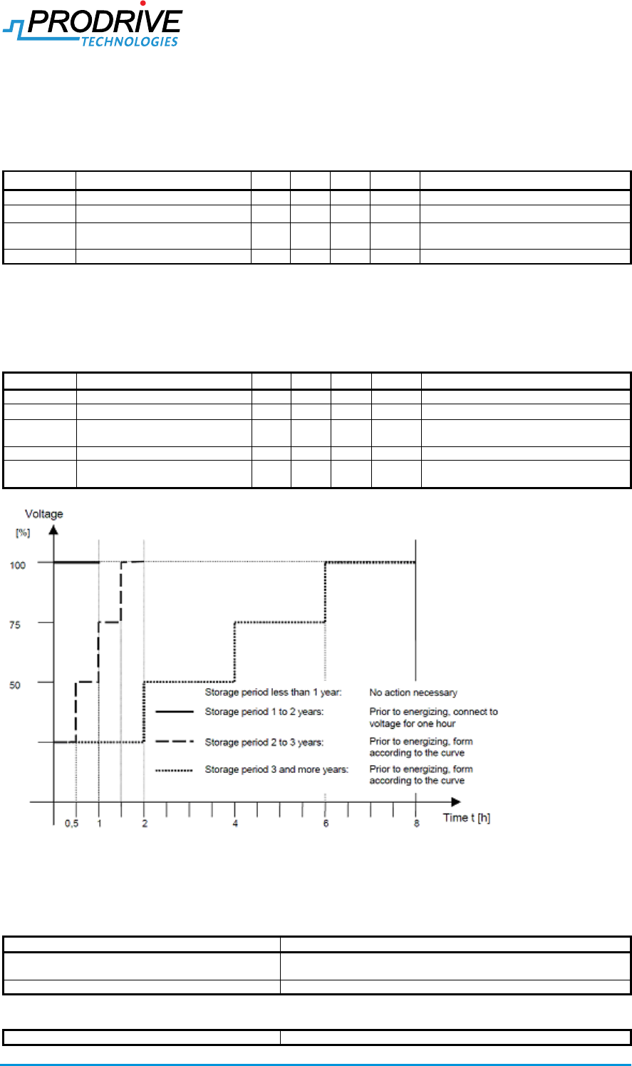
tSHELF
5
[yr]
Shelf life > 12 months requires
capacitor reforming, see Figure 6-1
Figure 6-1 Capacitor reforming
6.3. Shock and vibration
Table 6-3: Vibration test
Test procedure
IEC 60068-2-6
Condition
1Hz to 500 Hz; 20m/s² amplitude; 20 frequency cycles in each axis
Unpacked
Number of axes
3
Table 6-4: Shock test
Test procedure
IEC 60068-2-27

Confidential
Manual Carrier Controller 2019-01-23
SPD6752150121R17.docx Page 19 of 24
Condition
Peak acceleration: 250m/s², Duration: 6ms, 1000 shocks in each
axis, Half-sine
Packed
Number of axes
3 (positive and negative for each)
Table 6-5: Random vibration test
Test procedure
IEC 60068-2-64:2008
Condition
Acc. to table A.6, Categories 2a, 2b, 2c, Unpacked
Number of axes
3
6.4. Ingres protection
Table 6-6: Ingress protection
Region
Description
Value
Unit
Remarks
EU
IP rating of carrier controller
IP54
[-]
Protection from dust and splashing water
based on NEN-EN-IEC60529
IP rating is only achieved with connector
cables and/or protection caps.
USA/CA
UL enclosure rating of carrier
controller
Type 5
[-]
Enclosure rating is achieved with connector
cables and/or protection caps. (Available from
Phoenix 1414148). See the corresponding
connector paragraph in chapter 3 for correct
cables and/or protection caps.
6.5. Disposal
This product should be treated as industrial waste when disposed. Dispose accordingly and comply
with all local regulations.

Confidential
Manual Carrier Controller 2019-01-23
SPD6752150121R17.docx Page 20 of 24
7. Radio
FCC (UL/CSA models)
This device complies with Part 15 of the FCC Rules.
Operation is subject to the following two conditions:
(1) this device may not cause harmful interference, and
(2) this device must accept any interference received, including interference that may cause
undesired operation.
Note: This equipment has been tested and found to comply with the limits for a Class B digital
device, pursuant to part 15 of the FCC Rules. These limits are designed to provide reasonable
protection against harmful interference in a residential installation. This equipment generates, uses
and can radiate radio frequency energy and, if not installed and used in accordance with the
instructions, may cause harmful interference to radio communications. However, there is no
guarantee that interference will not occur in a particular installation. If this equipment does cause
harmful interference to radio or television reception, which can be determined by turning the
equipment off and on, the user is encouraged to try to correct the interference by one or more of
the following measures:
Reorient or relocate the receiving antenna.
Increase the separation between the equipment and receiver.
Connect the equipment into an outlet on a circuit different from that to which the receiver is
connected.
Consult the dealer or an experienced radio/TV technician for help.
RSS-247 of Industry Canada (UL/CSA models)
ENGLISH
This device complies with Industry Canada licence-exempt RSS standard(s).
Operation is subject to the following two conditions:
1. this device may not cause interference, and
2. this device must accept any interference, including interference that may cause undesired
operation of the device.
This radio transmitter has been approved by Industry Canada to operate with the antenna types
listed in the respective Operating Instructions with the maximum permissible gain and required
antenna impedance for each antenna type indicated. Antenna types not included in this list, having
a gain greater than the maximum gain indicated for that type, are strictly prohibited for use with this
device.
Under Industry Canada regulations, this radio transmitter may only operate using an antenna of a
type and maximum (or lesser) gain approved for the transmitter by Industry Canada. To reduce
potential radio interference to other users, the antenna type and its gain should be so chosen that
the equivalent isotropically radiated power (e.i.r.p.) is not more than that necessary for successful
communication.
To reduce potential radio interference to other users, the antenna type and its gain should be so
chosen that the equivalent isotropically radiated power (e.i.r.p.) is not more than that permitted for
successful communication.
That the device for the band 5150-5250 MHz is only for indoor usage to reduce potential for
harmful interference to co-channel mobile satellite systems.
Users should also be cautioned to take note that high power radars are allocated as primary users
(meaning they have priority) of 5250-5350 MHz and 5650-5850 MHz and these radars could cause
interference and/or damage to LE-LAN devices.
This equipment complies with IC RSS-102 radiation exposure limits set forth for an uncontrolled
environment. This equipment should be installed and operated with minimum distance 20cm
between the radiator & your body.
FRENCH
Le présent appareil est conforme aux CNR d'Industrie Canada applicables aux appareils radio
exempts de licence. L'exploitation est autorisée aux deux conditions suivantes:
(1) l'appareil ne doit pas produire de brouillage, et
Confidential
Manual Carrier Controller 2019-01-23
SPD6752150121R17.docx Page 21 of 24
(2) l'appareil doit accepter tout brouillage radioélectrique subi, même si le brouillage est susceptible
d'en compromettre le fonctionnement.
Industrie Canada a autorisé cet émetteur radio à fonctionner avec les types d'antenne énumérés
dans le mode d'emploi correspondant, avec le gain maximal admissible et l'impédance d'antenne
requise pour chaque type d'antenne indiqué. Les types d'antenne non inclus dans cette liste, ayant
un gain supérieur au gain maximal indiqué pour ce type, sont strictement interdits d'utilisation avec
cet appareil.
Selon les réglementations d'Industrie Canada, cet émetteur radio ne peut fonctionner qu'avec une
antenne d'un type et d'un gain maximal (ou inférieur) approuvé pour l'émetteur par Industrie
Canada. Pour réduire le risque de brouillage radioélectrique causé aux autres utilisateurs, le type
d’antenne et son gain doivent être choisis de manière à ce que la puissance rayonnée isotrope
équivalente (e.i.r.p.) ne soit pas supérieure à celle nécessaire au succès de la communication.
Pour réduire le risque de brouillage radioélectrique causé aux autres utilisateurs, le type d’antenne
et son gain doivent être choisis de manière à ce que la puissance rayonnée isotrope équivalente
(par exemple) ne soit pas supérieure à celle autorisée pour une communication réussie.
Que le dispositif pour la bande 5150-5250 MHz soit uniquement destiné à une utilisation en
intérieur afin de réduire le risque de brouillage préjudiciable des systèmes de télécommunication
par satellite mobiles dans le même canal.
Les utilisateurs doivent également noter que les radars à haute puissance sont attribués en tant
qu'utilisateurs principaux (c'est-à-dire qu'ils ont la priorité) de 5250-5350 MHz et 5650-5850 MHz et
que ces radars peuvent causer des interférences et / ou des dommages aux dispositifs LE-LAN.
Cet équipement est conforme aux limites d'exposition au rayonnement IC RSS-102 définies pour
un environnement non contrôlé. Cet équipement doit être installé et utilisé à une distance minimale
de 20 cm entre le radiateur et votre corps.
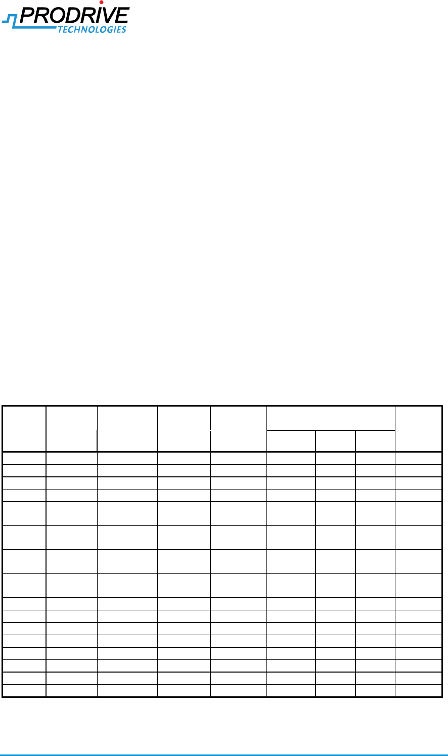
7.1. Channel support
The master controller supports the channels shown in Table 7-1.
Table 7-1: WLAN channel support
Channel
Center
frequency
[Mhz]
Frequency
range [Mhz]
Bandwidth
[Mhz]
Band
Channel limitations
Remarks
EU
CA
USA
36
5180
5170–5190
20
U-NII-1
Indoors
Indoors
-
40
5200
5190–5210
20
U-NII-1
Indoors
Indoors
-
44
5220
5210–5230
20
U-NII-1
Indoors
Indoors
-
48
5240
5230–5250
20
U-NII-1
Indoors
Indoors
-
52
5260
5250–5270
20
U-NII-2A
Indoors
DFS/TPC
DFS
DFS
56
5280
5270–5290
20
U-NII-2A
Indoors
DFS/TPC
DFS
DFS
60
5300
5290–5310
20
U-NII-2A
Indoors
DFS/TPC
DFS
DFS
64
5320
5310–5330
20
U-NII-2A
Indoors
DFS/TPC
DFS
DFS
100
5500
5490–5510
20
U-NII-2C
DFS/TPC
DFS
DFS
104
5520
5510–5530
20
U-NII-2C
DFS/TPC
DFS
DFS
108
5540
5530–5550
20
U-NII-2C
DFS/TPC
DFS
DFS
112
5560
5550–5570
20
U-NII-2C
DFS/TPC
DFS
DFS
116
5580
5570–5590
20
U-NII-2C
DFS/TPC
DFS
DFS
132
5660
5650–5670
20
U-NII-2C
DFS/TPC
DFS
DFS
136
5680
5670–5690
20
U-NII-2C
DFS/TPC
DFS
DFS
140
5700
5690–5710
20
U-NII-2C
DFS/TPC
DFS
DFS
7.2. List of supported antennas
RSS-247 of Industry Canada (UL/CSA models)
ENGLISH
Confidential
Manual Carrier Controller 2019-01-23
SPD6752150121R17.docx Page 22 of 24
This radio transmitter 9389A-CCMUL has been approved by Innovation, Science and Economic
Development Canada to operate with the antenna types listed below, with the maximum
permissible gain indicated. Antenna types not included in this list that have a gain greater than the
maximum gain indicated for any type listed are strictly prohibited for use with this device.
FRENCH
Cet émetteur radio 9389A-CCMUL a été approuvé par Innovation, Sciences et Développement
économique Canada pour fonctionner avec les types d’antennes énumérés ci-dessous, avec le
gain maximal admissible indiqué. Les types d'antenne non inclus dans cette liste et dont le gain est
supérieur au gain maximal indiqué pour l'un des types répertoriés ne sont strictement pas autorisés
pour une utilisation avec cet appareil.
Table 7-2: List of supported antennas
Mfr
Mfr PN
Description
Impedance
Max. ant..
Gain.
SEW Eurodrive
Coupler R-SMA 5.0 GHz
SWG (Slotted Wave Guide)
Antenna
50 Ohm
-3.8 dBi
Eupen
RMC 12-CH
Eucaray 1/2" radiating cable
50 Ohm
0 dBi


Confidential
Manual Carrier Controller 2019-01-23
SPD6752150121R17.docx Page 24 of 24
Appendix A. Copyright License
The following table lists the copyrighted and or licensed items related to this product.
Table 8-1: Copyright Licenses
Component
License
Remark
Linux Kernel
GPLv2
GNU C Library
LGPL2.1