Prodrive Technologies SC2MCSIO SC2MCSIO RFID User Manual
Prodrive Technologies B.V. SC2MCSIO RFID Users Manual
Users Manual
/KKW/SSC 2.08 en Z1 IBA-SIGMA CONTROL FLUID
/KKW/SSC 2.08 Z1
20170413 074810

1 SIGMA CONTROL 2 Quick installation guide
1.1 Operating elements .......................................................................................................... 1
1.2 Display elements .............................................................................................................. 2
1.3 Main menu ....................................................................................................................... 2
1.4 Functions – Overview ....................................................................................................... 3
2 Regarding this Document
2.1 Using this document ......................................................................................................... 5
2.2 Copyright .......................................................................................................................... 5
2.2.1 Software .............................................................................................................. 5
2.3 Approvals ......................................................................................................................... 6
2.4 Updating the user manual ................................................................................................ 6
2.5 Symbols and labels .......................................................................................................... 6
2.5.1 Warnings ............................................................................................................. 7
2.5.2 Potential damage warnings ................................................................................ 7
2.5.3 Other alerts and their symbols ............................................................................ 8
3 Technical Data
3.1 SIGMA CONTROL 2 Controller ....................................................................................... 9
3.1.1 Versions and options .......................................................................................... 9
3.1.2 User interface with display, CPU and interfaces ................................................. 9
3.1.3 Inputs and outputs with MCSIO .......................................................................... 12
3.1.4 Input/output modules .......................................................................................... 12
3.1.5 Sensors ............................................................................................................... 14
4 Safety and Responsibility
4.1 Basic instructions ............................................................................................................. 16
4.2 Specified use .................................................................................................................... 16
4.3 Improper use .................................................................................................................... 16
5 Design and Function
5.1 The controller ................................................................................................................... 17
5.2 Operating panel ................................................................................................................ 19
5.2.1 Indicating and operating elements ...................................................................... 19
5.2.2 Display elements ................................................................................................ 20
5.2.3 RFID reader ........................................................................................................ 21
5.3 Display ............................................................................................................................ 21
5.3.1 Operating mode .................................................................................................. 22
5.3.2 Main menu .......................................................................................................... 23
5.3.3 Setting parameters ............................................................................................. 23
5.3.4 Activating keys with check boxes ....................................................................... 24
5.4 Access rights .................................................................................................................... 24
5.5 KAESER CONNECT ........................................................................................................ 25
5.6 Menus – overview ............................................................................................................ 26
5.6.1 Operating mode .................................................................................................. 26
5.6.2 Menu structure .................................................................................................... 27
5.7 Operating modes and control modes ............................................................................... 42
5.7.1 Operating modes ................................................................................................ 42
5.7.2 Control modes .................................................................................................... 43
5.7.3 Frequency-controlled drive (SFC) ....................................................................... 44
5.7.4 MODULATING control ........................................................................................ 45
6 Installation and Operating Conditions
6.1 Maintaining ambient conditions ........................................................................................ 46
6.2 Installation conditions ....................................................................................................... 46
Contents
No.: 9_9450 07 USE
User Manual Controller
SIGMA CONTROL 2 SCREW FLUID ≥4.0.X i

7 Installation
7.1 Reporting Transport Damage ........................................................................................... 47
7.2 Machine identification ....................................................................................................... 47
8 Initial Start-up
8.1 Outline .............................................................................................................................. 48
8.2 Configuring the controller ................................................................................................. 48
8.2.1 Selecting menu options ...................................................................................... 49
8.2.2 Setting the language ........................................................................................... 50
8.2.3 Noting the number of the KAESER Equipment Card ......................................... 51
8.2.4 User log-in with KAESER Equipment Card ........................................................ 52
8.2.5 Generating a password ....................................................................................... 53
8.2.6 Manual user log-in .............................................................................................. 54
8.2.7 Checking and setting time and date ................................................................... 55
8.2.8 Set the time zone ................................................................................................ 57
8.2.9 Setting display formats ....................................................................................... 57
8.2.10 Setting the display illumination ........................................................................... 60
8.2.11 Setting the contrast and the brightness .............................................................. 61
8.2.12 Activating the remote control .............................................................................. 61
8.2.13 IP configuration .................................................................................................. 62
8.2.14 Setting the e-mail function ................................................................................. 63
8.2.15 Configuring the time server ................................................................................ 65
8.3 Using KAESER CONNECT .............................................................................................. 66
8.3.1 Open KAESER CONNECT ................................................................................. 67
8.3.2 System status menu ........................................................................................... 68
8.3.3 Graphs menu ...................................................................................................... 69
8.3.4 Messages menu ................................................................................................. 71
8.3.5 I/O display menu ................................................................................................. 72
8.3.6 User management menu .................................................................................... 73
8.3.7 Settings ............................................................................................................... 76
8.3.8 Backup menu ...................................................................................................... 77
8.3.9 Closing KAESER CONNECT ............................................................................. 77
8.4 Adjusting the pressure parameters of the machine ......................................................... 78
8.4.1 Displaying pressure parameters ......................................................................... 79
8.4.2 Configuring the pressure parameters ................................................................. 79
8.4.3 Activating/deactivating the «LOAD/IDLE» key .................................................... 82
8.5 Configuring machine start and stop ................................................................................. 83
8.5.1 Automatic start/stop in timer mode .................................................................... 83
8.5.2 Setting up the holiday period .............................................................................. 87
8.5.3 Starting the machine remotely (Remote ON/OFF) ............................................. 88
8.5.4 Activating the remote control ............................................................................. 90
8.5.5 Activating/deactivating the idle period "Venting period" function ....................... 91
8.5.6 Activating/deactivating and adjusting the "Autostart" function ............................ 91
8.6 Activating and adjusting the control modes ...................................................................... 94
8.6.1 Selecting a control mode .................................................................................... 94
8.6.2 Adjusting the idle time of DUAL control mode .................................................... 95
8.6.3 Adjusting the minimum running and unloaded period in QUADRO control
mode ...................................................................................................................
96
8.7 Electronic Thermal Management .................................................................................... 97
8.7.1 Activating the heat recovery for machine type 2 ................................................. 97
8.7.2 Activating the heat recovery for machine type 3 ................................................. 99
8.7.3 Deactivating heat recovery ................................................................................. 100
8.8 Refrigerated dryer ........................................................................................................... 101
8.8.1 Setting the operating mode ................................................................................. 101
8.8.2 Output messages ................................................................................................ 102
Contents
ii User Manual Controller
SIGMA CONTROL 2 SCREW FLUID ≥4.0.X No.: 9_9450 07 USE

8.8.3 Fault in the refrigerated dryer – compressed air quality has priority ................... 103
8.8.4 Fault in the refrigerated dryer – compressed air quantity has priority ................. 104
8.9 Configuring the machine for local mode .......................................................................... 105
8.9.1 Load control menu .............................................................................................. 105
8.9.2 Configuring the system setpoint pressure changeover using the clock .............. 106
8.9.3 Configuring the system setpoint pressure changeover using the timer .............. 109
8.10 Configuring the machine for master control ..................................................................... 111
8.10.1 List of the different master controllers ................................................................. 111
8.10.2 SAM 4.0 mode ................................................................................................... 111
8.10.3 Configuring PROFIBUS mode (SIGMA AIR MANAGER) ................................... 114
8.10.4 Configuring the master control of two machines in master/slave operation ...... 122
8.10.5 Configuring master control using the LOAD remote contact (e.g.,
SIGMA AIR MANAGER BASIC) ........................................................................
128
8.10.6 Configuring the master control with local/LOAD remote contact ....................... 130
8.10.7 Setting the setpoint pressure pre-selection via remote contact ......................... 133
8.10.8 Configuring master control of compressors regulated by pressure switch ........ 134
8.10.9 Examples of time settings for equal overall load ............................................... 140
8.11 Configuring input and output signals ................................................................................ 141
8.11.1 Outputting important operational states of the machine ..................................... 141
8.11.2 Output input signals on the display ..................................................................... 143
8.11.3 Output measured values on the display ............................................................. 147
8.12 Activating remote acknowledgement .............................................................................. 152
8.12.1 Setting the remote acknowledgement function ................................................... 153
8.12.2 Activating the remote control .............................................................................. 153
8.12.3 Assigning an input .............................................................................................. 154
8.13 Linking to an external pressure transducer ..................................................................... 155
8.13.1 Pressure control menu ........................................................................................ 155
8.13.2 Assigning an input to an external pressure transducer ...................................... 155
8.14 Commissioning the machine ........................................................................................... 156
9 Operation
9.1 Switching on and off ......................................................................................................... 158
9.1.1 Switching on ....................................................................................................... 158
9.1.2 Switching off ....................................................................................................... 159
9.2 Switching off in an emergency and switching on again .................................................... 159
9.3 Acknowledging alarm and warning messages ................................................................. 160
9.4 Displaying messages ...................................................................................................... 161
9.4.1 Selecting the status menu .................................................................................. 162
9.5 Displaying the current operating mode ........................................................................... 163
9.6 Adjusting the working pressure ........................................................................................ 164
9.7 Displaying analog data .................................................................................................... 164
9.8 Displaying operating data ................................................................................................ 165
9.8.1 Checking the operating hours ............................................................................. 166
9.8.2 Checking the switching cycles ............................................................................ 167
9.9 Displaying the frequency converter settings ................................................................... 168
9.10 Setting the maintenance interval ..................................................................................... 168
9.11 Checking the safety relief valve ...................................................................................... 170
9.12 Checking the temperature sensor and overheating shutdown function ........................... 172
9.13 Save data ........................................................................................................................ 174
10 Fault Recognition and Rectification
10.1 Basic instructions ............................................................................................................. 175
10.2 Interpreting alarm messages ............................................................................................ 175
10.3 Interpreting warning messages ........................................................................................ 184
10.4 Interpreting operation messages ...................................................................................... 197
Contents
No.: 9_9450 07 USE
User Manual Controller
SIGMA CONTROL 2 SCREW FLUID ≥4.0.X iii

10.5 Interpreting diagnostic messages .................................................................................... 201
10.6 Interpreting system messages ......................................................................................... 202
11 Maintenance
11.1 Changing the buffer battery .............................................................................................. 203
12 Spares, Operating Materials, Service
12.1 Note the nameplate .......................................................................................................... 204
12.2 KAESER AIR SERVICE ................................................................................................... 204
12.3 Service Addresses ........................................................................................................... 204
12.4 Displaying the version number, machine model, part number and serial number .......... 204
13 Decommissioning, Storage and Transport
13.1 De-commissioning ............................................................................................................ 206
13.2 Packing ............................................................................................................................ 206
13.3 Storage ............................................................................................................................. 206
13.4 Transporting ..................................................................................................................... 206
13.5 Disposal ........................................................................................................................... 206
13.5.1 Battery disposal .................................................................................................. 206
Contents
iv User Manual Controller
SIGMA CONTROL 2 SCREW FLUID ≥4.0.X No.: 9_9450 07 USE

Fig. 1 Operating elements .................................................................................................................... 1
Fig. 2 Display elements ........................................................................................................................ 2
Fig. 3 MCS interfaces ........................................................................................................................... 10
Fig. 4 MCSIO interfaces ....................................................................................................................... 11
Fig. 5 MCS system design with IOM .................................................................................................... 18
Fig. 6 MCSIO system design ................................................................................................................ 18
Fig. 7 Indicating and operating elements ............................................................................................. 19
Fig. 8 Display elements ........................................................................................................................ 20
Fig. 9 RFID reader ................................................................................................................................ 21
Fig. 10 KAESER CONNECT for SIGMA CONTROL 2 ........................................................................... 25
Fig. 11 Back of the KAESER Equipment Card ....................................................................................... 52
Fig. 12 User log-in with KAESER Equipment Card ................................................................................ 52
Fig. 13 User log-in with KAESER Equipment Card ................................................................................ 53
Fig. 14 Manual user log-in ...................................................................................................................... 55
Fig. 15 Login window .............................................................................................................................. 67
Fig. 16 KAESER CONNECT for SIGMA CONTROL 2 ........................................................................... 67
Fig. 17 Select language: window ............................................................................................................ 68
Fig. 18
System status
menu ................................................................................................................... 68
Fig. 19 Main menu .................................................................................................................................. 69
Fig. 20
Graphs
(illustration similar) ......................................................................................................... 70
Fig. 21 Arrow keys .................................................................................................................................. 70
Fig. 22
Messages
.................................................................................................................................. 72
Fig. 23
I/O display
(illustration similar) ................................................................................................... 73
Fig. 24
User management
menu ............................................................................................................ 74
Fig. 25
Log on for write access:
window ................................................................................................ 74
Fig. 26
User management
menu ............................................................................................................ 75
Fig. 27
Settings
..................................................................................................................................... 76
Fig. 28
Backup
menu ............................................................................................................................. 77
Fig. 29 PROFIBUS plug wiring ............................................................................................................... 115
Fig. 30 Electrical diagram example with SIGMA AIR MANAGER .......................................................... 116
Fig. 31 Communication interface ............................................................................................................ 117
Fig. 32 Inserting the communication module .......................................................................................... 118
Fig. 33 Front plate of the PROFIBUScommunication module ................................................................ 118
Fig. 34 Direct connection of two SIGMA CONTROL 2 ........................................................................... 123
Fig. 35 LOAD remote contact ................................................................................................................. 128
Fig. 36 Wiring diagram for local/LOAD remote contact: ......................................................................... 131
Fig. 37 Machine with pressure switch regulation .................................................................................... 136
Fig. 38 Function diagram ........................................................................................................................ 139
Fig. 39 Switching on and off ................................................................................................................... 158
Fig. 40 Switching off in an emergency ................................................................................................... 159
Fig. 41 Acknowledging messages .......................................................................................................... 160
Fig. 42 Battery disposal .......................................................................................................................... 206
List of Illustrations
No.: 9_9450 07 USE
User Manual Controller
SIGMA CONTROL 2 SCREW FLUID ≥4.0.X v

List of Illustrations
vi User Manual Controller
SIGMA CONTROL 2 SCREW FLUID ≥4.0.X No.: 9_9450 07 USE

Tab. 1 Operating elements .................................................................................................................... 1
Tab. 2 Display elements ........................................................................................................................ 2
Tab. 3 Main menu .................................................................................................................................. 2
Tab. 4 Functions – Overview ................................................................................................................. 3
Tab. 5 Danger levels and their definition (personal injury) .................................................................... 7
Tab. 6 Danger levels and their definition (damage to property) ............................................................ 7
Tab. 7 Formatting options ...................................................................................................................... 8
Tab. 8 Versions and options .................................................................................................................. 9
Tab. 9 User interface ............................................................................................................................. 9
Tab. 10 Display data ................................................................................................................................ 10
Tab. 11 MCS interfaces ........................................................................................................................... 10
Tab. 12 MCSIO interfaces ....................................................................................................................... 11
Tab. 13 RFID ........................................................................................................................................... 11
Tab. 14 MCSIO inputs and outputs ......................................................................................................... 12
Tab. 15 Cable lengths ............................................................................................................................. 12
Tab. 16 IOM 1 .......................................................................................................................................... 13
Tab. 17 IOM 2 .......................................................................................................................................... 13
Tab. 18 IOM 3 .......................................................................................................................................... 13
Tab. 19 Power supply specifications ....................................................................................................... 14
Tab. 20 Cable lengths ............................................................................................................................. 14
Tab. 21 IOM degree of protection ............................................................................................................ 14
Tab. 22 IOM dimensions ......................................................................................................................... 14
Tab. 23 Pressure transducer ................................................................................................................... 14
Tab. 24 Resistance thermometer ............................................................................................................ 15
Tab. 25 Operating elements .................................................................................................................... 19
Tab. 26 Display elements ........................................................................................................................ 20
Tab. 27 RFID reader ................................................................................................................................ 21
Tab. 28 Header ........................................................................................................................................ 22
Tab. 29 Reset check box status .............................................................................................................. 24
Tab. 30 Check box status ........................................................................................................................ 24
Tab. 31 KAESER CONNECT functions ................................................................................................... 25
Tab. 32 Menu structure .......................................................................................................................... 27
Tab. 33
Status
menu ............................................................................................................................... 30
Tab. 34
Configuration
menu .................................................................................................................... 32
Tab. 35
Pressure control
menu ............................................................................................................... 34
Tab. 36
I/O periphery
menu ..................................................................................................................... 36
Tab. 37
Communication
menu ................................................................................................................ 38
Tab. 38
Connections
menu ..................................................................................................................... 39
Tab. 39
Components
menu ..................................................................................................................... 40
Tab. 40
Power switching
menu ............................................................................................................... 41
Tab. 41 Machine identification ................................................................................................................. 47
Tab. 42 Remote control identification ...................................................................................................... 47
Tab. 43 Machine identification ................................................................................................................. 47
Tab. 44 Display languages ...................................................................................................................... 50
Tab. 45 Date formats ............................................................................................................................... 57
Tab. 46 Time formats .............................................................................................................................. 58
Tab. 47 Units of pressure ........................................................................................................................ 59
Tab. 48 Units of temperature ................................................................................................................... 59
Tab. 49 Display illumination ..................................................................................................................... 60
Tab. 50 Network parameters ................................................................................................................... 63
Tab. 51 E-mail parameters ...................................................................................................................... 64
Tab. 52 Arrow key functions .................................................................................................................... 70
Tab. 53 Compressor pressure parameters .............................................................................................. 78
Tab. 54 Setting limits for the system setpoint pressure (* Cut-in pressure min) ...................................... 79
List of Tables
No.: 9_9450 07 USE
User Manual Controller
SIGMA CONTROL 2 SCREW FLUID ≥4.0.X vii

Tab. 55 Pressure condition for LOAD ...................................................................................................... 80
Tab. 56 Pressure conditions for IDLE ...................................................................................................... 80
Tab. 57 Example: activated output .......................................................................................................... 80
Tab. 58 Displaying and adjusting parameters ......................................................................................... 81
Tab. 59 Settings for machine start and stop ............................................................................................ 83
Tab. 60 User-defined clock program machine ON/OFF .......................................................................... 84
Tab. 61 Example of a machine ON/OFF clock program .......................................................................... 85
Tab. 62 Autostart delay period ................................................................................................................ 92
Tab. 63 Machine type and ETM design ................................................................................................... 97
Tab. 64 Local operating mode (local mode) ............................................................................................ 105
Tab. 65 User-defined clock program ...................................................................................................... 106
Tab. 66 Example of system pressure changeover switching points ........................................................ 107
Tab. 67 Master control – overview ........................................................................................................... 111
Tab. 68 Parameters for monitoring for communication malfunction ........................................................ 114
Tab. 69 PROFIBUS DP pin connection ................................................................................................... 115
Tab. 70 Master-slave configuration procedure ........................................................................................ 122
Tab. 71 Function diagram ........................................................................................................................ 138
Tab. 72 Example for a clock program for equal duty cycling during the day ........................................... 140
Tab. 73 Example for a clock program for equal duty cycling during the week ........................................ 140
Tab. 74 Assigned output signals ............................................................................................................. 141
Tab. 75 Logic settings ............................................................................................................................. 145
Tab. 76 Assigned analog measured values ............................................................................................ 147
Tab. 77 Transmitting a pressure transducer value .................................................................................. 155
Tab. 78 Check list for commissioning the machine ................................................................................. 156
Tab. 79 Message sequence 1 ................................................................................................................. 160
Tab. 80 Message sequence 2 ................................................................................................................. 160
Tab. 81 Information of a message ........................................................................................................... 161
Tab. 82 Message abbreviations .............................................................................................................. 161
Tab. 83 Operating mode display ............................................................................................................. 163
Tab. 84 Abbreviation of operating modes ................................................................................................ 164
Tab. 85 Check box status ........................................................................................................................ 170
Tab. 86 Fault messages, possible causes and remedies ........................................................................ 175
Tab. 87 Warning messages and remedies .............................................................................................. 185
Tab. 88 Operational messages ............................................................................................................... 198
Tab. 89 System messages and remedies ............................................................................................... 202
List of Tables
viii User Manual Controller
SIGMA CONTROL 2 SCREW FLUID ≥4.0.X No.: 9_9450 07 USE
1 SIGMA CONTROL 2 Quick installation guide
1.1 Operating elements
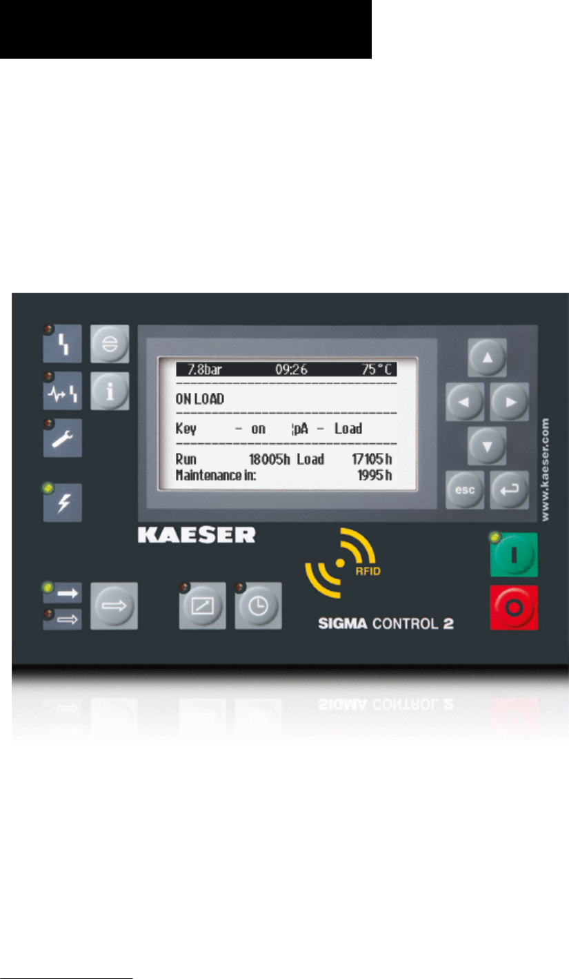
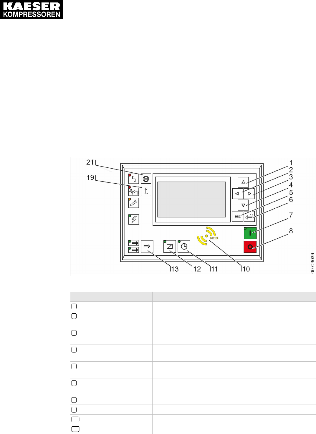
Fig. 1 Operating elements
Item Description Function
1«Up» Scrolls up the menu options. Increases a parameter value.
2«Left» Jumps to the left.
Moves the cursor position to the next left field.
3«Right» Jumps to the right.
Moves the cursor position to the next right field.
4«Down» Scrolls down the menu options.
Reduces a parameter value.
5«Escape» Returns to the next higher menu option level.
Exits the edit mode without saving.
6«Enter» Jumps to the selected submenu option.
Exits the edit mode and saves.
7«ON» Switches the machine on.
8«OFF» Switches the machine off.
10 RFID RFID reader for user log-in with RFID Equipment Card.
11 «Timer control» Switches the timer control on and off.
12 «Remote control» Switches the remote control on and off.
13 «LOAD/IDLE» Toggles between the LOAD and IDLE modes.
19 «Information» Displays the event memory.
21 «Acknowledgement» Confirms/acknowledges alarms and warning messages.
If permissible: Resets the fault counter (RESET).
Tab. 1 Operating elements
1 SIGMA CONTROL 2 Quick installation guide
1.1 Operating elements
No.: 9_9450 07 USE
User Manual Controller
SIGMA CONTROL 2 SCREW FLUID ≥4.0.X 1
1.2 Display elements
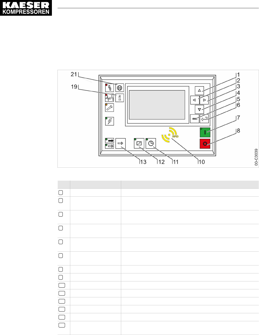
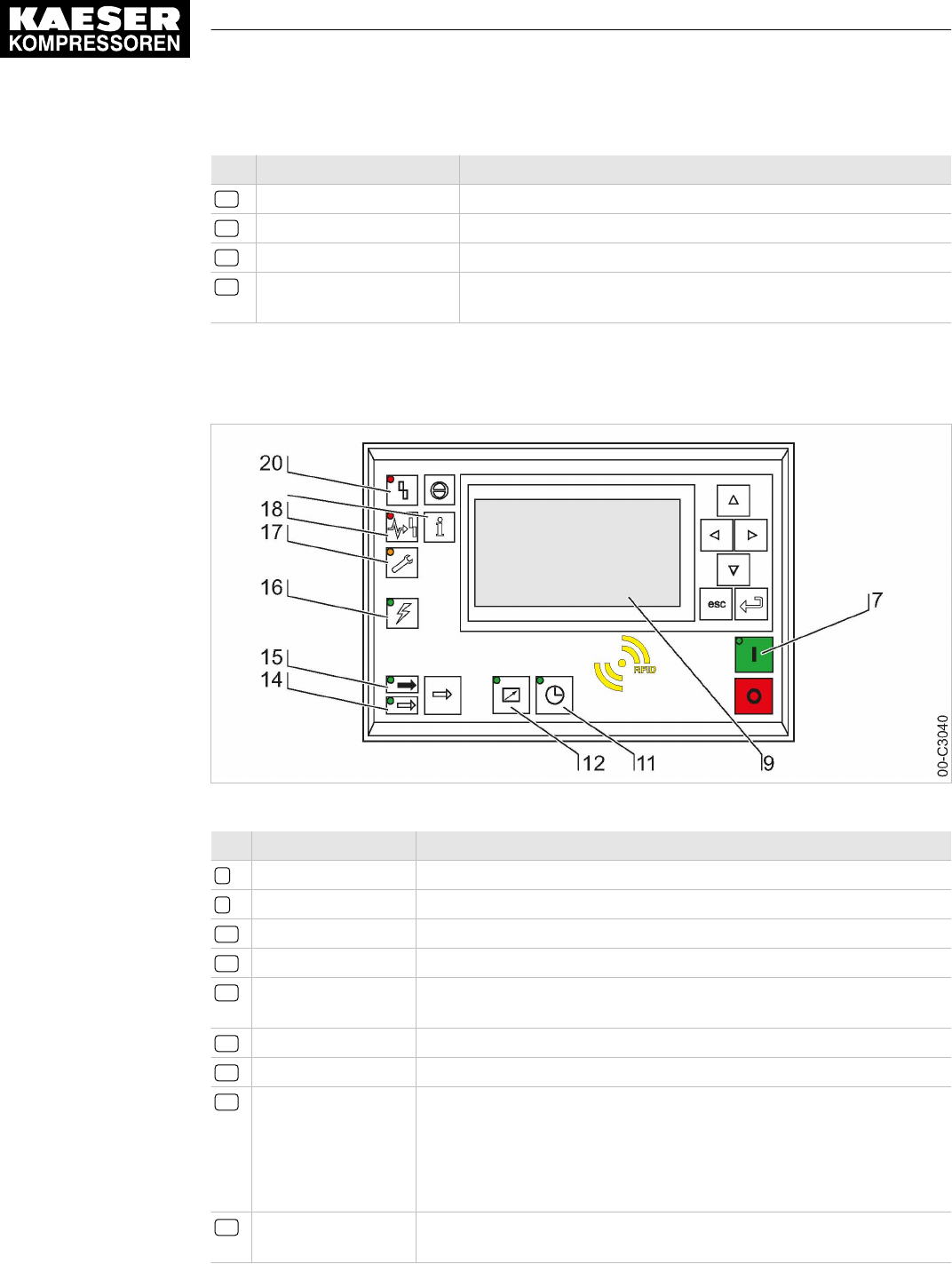
Fig. 2 Display elements
Item Description Function
7
ON
Display illuminates green when the machine switched on.
9
Display
Graphic display with 8 lines and 30 characters per line.
11
Timer control
Continuous green light when the machine is controlled by the timer.
12
Remote control
Continuous green light when the machine is in remote control.
14
IDLE
Continuous green light when the machine is running in IDLE. Flashes
when the «LOAD/IDLE» toggle key is pressed.
15
LOAD
Continuous green light when the machine is running in LOAD.
16
Controller voltage
Continuous green light when voltage is applied to the controller.
17
Warning
Flashes in yellow in the following events:
■ Maintenance work due
■ Warning message
Continuous yellow light after acknowledgement.
18
Communications
error
Continuous red light to indicate a defective communication connection,
or an external alarm message without machine shutdown.
20
Alarm
Flashes red to indicate a machine alarm.
Continuous red light after acknowledgement.
Tab. 2 Display elements
1.3 Main menu
Press «Up» / «Down» / «Enter» to open the main menu.
Menu No. Menu designation Function
1 Status Displays messages, statistics and status information.
1 SIGMA CONTROL 2 Quick installation guide
1.2 Display elements
2User Manual Controller
SIGMA CONTROL 2 SCREW FLUID ≥4.0.X No.: 9_9450 07 USE

Menu No. Menu designation Function
2 Performance data Displays measured data of the machine and its components (e.g.,
motors).
3 Operating data Displays operating hours, switching cycles and energy data.
4 Maintenance Displays maintenance data of the machine and its components.
5 Configuration Setting of machine parameters, compressed air system and acces‐
sories.
6 Compressor clock Setting the timer control.
7 User Manual user log-in and password administration.
8 Communication Setting the Ethernet interface, COM modules and control center
connection.
9 Machine test Safety relief valve and temperature sensor test and shutdown at ex‐
cessive temperature.
10 Components Display of settings on machine components, e.g. the power switch‐
ing unit.
Tab. 3 Main menu
See Chapter 5.6.2 for the complete menu structure.
1.4 Functions – Overview
Function Menu
No.
Action steps Chapter
Setting the contrast Main
menu
Press and hold «Information» – «Up» / «Down». 8.2.11
Setting the brightness Main
menu
Press and hold «Information» – «Left» / «Right». 8.2.11
Setting the language Main
menu
«Enter» – «Up» – «Enter» – «Up» / «Down». 8.2.2
Setting date, time and
time zone
5.1
<Configuration – General>
. 8.2.7
Identification with
RFID Equipment Card
– 8.2.4
Setting pressure pa‐
rameters
5.2.2
<Configuration – Pressure control – Pressure settings –
pA/pB>
.
8.4
Setting the
«Timer control»
6
<Compressor clock – Setting timing program>
. 8.5.1
Activating the
«Timer control» key
6
<Compressor clock – Key clock – ☑>
. 8.5.1.3
Activating
«Timer control»
– Activate the «Timer control» key – Press
«Timer control».
8.5.1.4
1 SIGMA CONTROL 2 Quick installation guide
1.4 Functions – Overview
No.: 9_9450 07 USE
User Manual Controller
SIGMA CONTROL 2 SCREW FLUID ≥4.0.X 3

Function Menu
No.
Action steps Chapter
Activate
the «Remote control»
key
5.2.3
5.4.1
5.5
<Configuration – Compressor start – Compressor on –
Key remote – ☑>
.
8.2.12
Activating the
«Remote control»
– Activate the «Remote control» key – Press
«Remote control».
8.2.12
Setting the control
mode
5.3 Select
<Configuration – Control mode – Local mode –
Control mode>
.
8.6.1
Setting up the holiday
period
5.4.2
<Configuration – Compressor start – Compressor off –
Holidays – Start/End/☑>
.
8.5.2
Displaying operating
data
3
<Operating data – Operating hours / Switching cycles>
. 9.8
Setting the mainte‐
nance interval
4
<Maintenance – Select/set component>
. 9.10
Checking the safety re‐
lief valve
9.1 For the test process, see Chapter. 9.11
High temperature shut‐
down test
9.1 For the test process, see Chapter. 9.12
Alarm messages 1.1.1 An alarm message causes the machine to shut down.
The
Alarm
LED flashes red. Alarm messages are identi‐
fied with the letter A. Example:
<0002 S k 31/12/2017 13:14:15 Motor temperature ⇞> .
10.2
Warning messages 1.1.1 If maintenance work is to be carried out or if the warning
is displayed before an alarm, the yellow
Warning
LED
flashes. Warning messages are identified with the let‐
ter W.
10.3
Operational messages 1.1.1 Operational messages provide information about the
current operational state of the machine. Operational
messages are identified with the letter O.
10.4
Diagnostic messages 1.1.1 A diagnostic message causes the machine to shut
down. They provide information on the status of the con‐
troller, the connected input and output modules and sup‐
port an authorized KAESER service representative in
troubleshooting. Diagnostic messages are identified with
the letter D.
10.5
System messages 1.1.1 A system message causes the machine to shut down.
System messages are identified with the letter Y.
10.6
Tab. 4 Functions – Overview
Settings can be made after log-in with the RFID Equipment Card and password access level
2.
1 SIGMA CONTROL 2 Quick installation guide
1.4 Functions – Overview
4User Manual Controller
SIGMA CONTROL 2 SCREW FLUID ≥4.0.X No.: 9_9450 07 USE

2 Regarding this Document
2.1 Using this document
The user manual contains important information to the entire life cycle of SIGMA CONTROL 2.
The user manual is a component of the product.
➤ Keep the user manual in a safe place throughout the life of SIGMA CONTROL 2.
➤ Pass the user manual on to the next owner/user of the machine.
➤ Ensure that all amendments received are inserted into the user manual.
2.2 Copyright
This user manual is protected by copyright. Any queries regarding the use or duplication of this
documentation should be referred to KAESER. Correct use of information will be fully supported.
2.2.1 Software
The software used in SIGMA CONTROL 2 contains copyright-protected software packages which
are licensed as Open Source.
A copy of these licenses is contained in SIGMA CONTROL 2.
Display the licenses by pointing your browser to the "COPYING" file in the root directory of
SIGMA CONTROL 2.
URL:
http:// <Hostname>/COPYING
The licenses can also be found under these addresses:
http://www.gnu.org/licenses
http://code.google.com/p/curve25519-donna/
Within three years from receipt of SIGMA CONTROL 2, you may obtain the complete source code
by sending a corresponding order to the following address:
Technical Office Electrical Design
KAESER KOMPRESSOREN SE
96450 Coburg, Postfach 2143
Germany
This offer is valid for anybody having this information.
2 Regarding this Document
2.1 Using this document
No.: 9_9450 07 USE
User Manual Controller
SIGMA CONTROL 2 SCREW FLUID ≥4.0.X 5

2.3 Approvals
The product has the following approvals:
■ This equipment has been tested and found to comply with the limits for a Class B digital de‐
vice, pursuant to Part 15 of the FCC Rules. These limits are designed to provide reasonable
protection against harmful interference in a residential installation. This equipment generates,
uses and can radiate radio frequency energy and, if not installed and used in accordance with
the instructions, may cause harmful interference to radio communications. However, there is
no guarantee that interference will not occur in a particular installation. If this equipment does
cause harmful interference to radio or television reception, which can be determined by turning
the equipment off and on, the user is encouraged to try to correct the interference by one of the
following measures:
─ Reorient or Relocate the receiving antenna
─ Increase the separation between the equipment and receiver
─ Connect the equipment into an outlet on a circuit different from that to which the receiver is
connected
─ Consult the dealer or an experienced radio/TV technician for help
■ To assure continued compliance, any changes or modifications not expressly approved by the
party responsible for compliance could void the user's authority to operate this equipment. (Ex‐
ample - use only shielded interface cables when connecting to computer or peripheral devi‐
ces).
■ This device complies with Part 15 of the FCC Rules. Operation is subject to the following two
conditions:
─ This device may not cause harmful interference, and
─ This device must accept any interference received, including interference that may cause
undesired operation
■ This device complies with Industry Canada licence-exempt RSS standard(s). Operation is sub‐
ject to the following two conditions:
─ This device may not cause interference and
─ This device must accept any interference, including interference that may cause undesired
operation of the device
■ Le présent appareil est conforme aux CNR d'Industrie Canada applicables aux appareils radio
exempts de licence. L'exploitation est autorisée aux deux conditions suivantes :
─ l'appareil ne doit pas produire de brouillage, et
─ l'utilisateur de l'appareil doit accepter tout brouillage radioélectrique subi, même si le brouil‐
lage est susceptible d'en compromettre le fonctionnement
2.4 Updating the user manual
The page http://www.kaeser.com/int-en/manuals/response.aspx of our website provides frequently
updated versions of this user manual.
➤ Download the user manual in your language.
2.5 Symbols and labels
➤ Please note the symbols and labels used in this document.
2 Regarding this Document
2.3 Approvals
6User Manual Controller
SIGMA CONTROL 2 SCREW FLUID ≥4.0.X No.: 9_9450 07 USE

2.5.1 Warnings
Warning notices indicate dangers that may result in injury when disregarded.
Warning notices indicate three levels of danger identified by the corresponding signal word:
Signal term Meaning Consequences of non-compliance
DANGER Warns of an imminent danger Will result in death or severe injury
WARNING Warns of a potentially imminent danger May result in death or severe injury
CAUTION Warns of a potentially dangerous situation May result in a moderate physical injury
Tab. 5 Danger levels and their definition (personal injury)
Warning notices preceding a chapter apply to the entire chapter, including all sub-sections.
Example:
The type and source of the imminent danger is shown here!
The possible consequences of ignoring a warning are shown here.
If you ignore the warning notice, the "DANGER" signal word indicates a lethal or severe in‐
jury will occur.
➤ The measures required to protect yourself from danger are shown here.
Warning notes referring to a sub-section or the subsequent action are integrated into the procedure
and numbered as an action.
Example:
1.
The type and source of the imminent danger is shown here!
The possible consequences of ignoring a warning are shown here.
If you ignore the warning notice, the "WARNING" signal word indicates that a lethal or severe
injury may occur.
➤ The measures required to protect yourself from danger are shown here.
2. Always read and comply with warning instructions.
2.5.2 Potential damage warnings
Contrary to the warnings shown above, damage warnings do not indicate a potential personal in‐
jury.
Warning notices for damages are identified by their signal term.
Signal term Meaning Consequences of non-compliance
NOTE Warns of a potentially dangerous situation Damage to property is possible
Tab. 6 Danger levels and their definition (damage to property)
Example:
2 Regarding this Document
2.5 Symbols and labels
No.: 9_9450 07 USE
User Manual Controller
SIGMA CONTROL 2 SCREW FLUID ≥4.0.X 7

The type and source of the imminent danger is shown here!
Potential effects when ignoring the warning are indicated here.
➤ The protective measures against the damages are shown here.
➤ Carefully read and fully comply with warnings against damages.
2.5.3 Other alerts and their symbols
The meaning of names is emphasized by different formatting. Depending on the font, not all for‐
matting options can be realized.
Name Formatting Example
Operating state UPPER CASE LOAD
Item number ... Open valve 4
Indication
italic ON
LED
Key « ... » «ON» key
Menu option
< ... > <Configuration>
Menu path
<Menu 1 – Menu 2 – ...> <Configuration – Pressure control>
activated ... The minutes display flashes. 00:00:00
Tab. 7 Formatting options
This symbol identifies particularly important information.
Material Here you will find details on special tools, operating materials or spare parts.
Precondition Here you will find conditional requirements necessary to carry out the task.
The conditions relevant to safety shown here will help you to avoid dangerous situations.
➤ This symbol denotes lists of actions comprising one stage of a task.
Operating instructions with several steps are numbered in the sequence of the operating steps.
Information referring to potential problems are identified by a question mark.
The cause is named in the help text ...
➤ ... as is a solution.
This symbol identifies important information or measures regarding the protection of the envi‐
ronment.
Further information Further subjects are introduced here.
2 Regarding this Document
2.5 Symbols and labels
8User Manual Controller
SIGMA CONTROL 2 SCREW FLUID ≥4.0.X No.: 9_9450 07 USE

3 Technical Data
3.1 SIGMA CONTROL 2 Controller
Industrial computer
■ Internal temperature monitoring
■ Internal low voltage monitoring
■ Battery-buffered real-time clock
─ Battery service span more than 10 years
─ Battery replaceable
3.1.1 Versions and options
SIGMA CONTROL 2 is offered in different designs.
Type Prepared for connection to control center Connection to control technology not
provided
Option C3 C48
Compo‐
nents
Main Control System (MCS): Slot for an
optional communication module (to con‐
nect to a control center)
Main Control System Input Output
(MCSIO): Digital and analog inputs and
outputs integrated
Input-Output-Module (IOM): Modules with
digital and analog inputs and outputs.
Tab. 8 Versions and options
3.1.2 User interface with display, CPU and interfaces
User interface
Feature MCS MCSIO
Material Plastics
Width [in.] 7.5
Height [in.] 5.1
Depth [in.] 1.8 2.4
Number of membrane keys 13
Number of LEDs 9
Degree of protection, control cabinet exterior IP 54
Degree of protection, control cabinet interior IP 20
Voltage [V] 24
Current [A] 0.3 2.5
Voltage source Input/output module External
Tab. 9 User interface
3 Technical Data
3.1 SIGMA CONTROL 2 Controller
No.: 9_9450 07 USE
User Manual Controller
SIGMA CONTROL 2 SCREW FLUID ≥4.0.X 9

Display
Feature Value
Graphical display [px] 255 x 128
Width [in.] 3.2
Height [in.] 1.6
Maximum number of lines/characters 8/30
Colors Black/white with grey scale
Lighting LED backlit
px = pixel
Tab. 10 Display data
Fig. 3 MCS interfaces
Identification Interface Connection
X1 Ethernet 10/100 Base T RJ 45 socket
X2 I/O bus 9-pole SUB-D pins
X3 RS485–FC (USS interface) 9-pole SUB-D socket
X4 Com modules,
slot for communications module
Module optional for:
PROFIBUS, PROFINET,
Modbus RTU, Modbus TCP,
DeviceNet
X5 SD card, SD card slot SD/SDHC card
X6 FG Functional ground (FG)
The positions of the interfaces X1–X6 are marked on the rear of the controller.
Tab. 11 MCS interfaces
3 Technical Data
3.1 SIGMA CONTROL 2 Controller
10 User Manual Controller
SIGMA CONTROL 2 SCREW FLUID ≥4.0.X No.: 9_9450 07 USE

Fig. 4 MCSIO interfaces
Marking Interface Connection
X1 Ethernet 10/100 Base T RJ 45 socket
X3 RS485–FC (USS interface) 9-pole SUB-D socket
X5 SD card, SD card slot SD/SDHC card
X6 FG Functional ground (FG)
X7 24 VDC, DII Power supply 24 VDC
Digital inputs DII1.00–DII1.05
X8 DII/DOT Digital inputs DII1.06–DII1.07
Digital outputs DOT1.00–DOT1.01
X9 AII/AIR Analog input current 0–20 mA,
AII1.00–AII1.01
Analog input resistor AIR1.00–
AIR1.01
X10 DOR Digital output relay 250 VAC, 4 A
DOR1.00–DOR1.04
The positions of the interfaces X1–X10 are marked on the rear of the controller.
Tab. 12 MCSIO interfaces
Identification with RFID Equipment Card
Feature Value
Hardware on the SIGMA CONTROL 2 controller RFID write/read device
Hardware (external) RFID Equipment Card
Recognition distance [in.] Max. 2
3 Technical Data
3.1 SIGMA CONTROL 2 Controller
No.: 9_9450 07 USE
User Manual Controller
SIGMA CONTROL 2 SCREW FLUID ≥4.0.X 11

Feature Value
Frequency [MHz] 13.56
Tab. 13 RFID
3.1.3 Inputs and outputs with MCSIO
Integrated inputs and outputs with MCSIO type controller
Input/Output Number
Digital input (DI), 24 VDC 8
Digital output transistor (DOT), 24 VDC, 0.5 A 2
Analog input current (AII), 0–20 mA 2
Analog input resistor (AIR), PT100 2
Digital output relay (DOR), 250 VAC, 4 A 5
Tab. 14 MCSIO inputs and outputs
3.1.3.1 Maximum cable lengths
Input/Output Cable length [ft.]
Analog input current (AII),
Analog input resistor (AIR)
Analog output current (AOI)
< 100
Digital input (DI),
Digital output relay (DOR)
< 330
Digital output transistor (DOT) < 100
Tab. 15 Cable lengths
3.1.4 Input/output modules
IOM modules only in combination with the MCS controller type
There are three different types of input/output modules with different numbers of inputs and out‐
puts.
The number of input/output modules actually available depends on the machine type and the avail‐
able options.
Refer to the machine's wiring diagram for the input/output modules installed in your equipment.
The input/output module features:
■ Internal temperature monitoring
■ Internal low voltage monitoring
■ LED indication of operational status
3 Technical Data
3.1 SIGMA CONTROL 2 Controller
12 User Manual Controller
SIGMA CONTROL 2 SCREW FLUID ≥4.0.X No.: 9_9450 07 USE

IOM 1
Input/Output Input/output module 1
Internal, into
the control
cabinet
Available in
parallel on
both sides
External, into
the compres‐
sor interior
Digital input (DI), 24 VDC 4 10 2
Analog input current (AII), 0–20 mA – 1 2
Analog input resistor (AIR), PT100 – 1 3
Digital output relay (DOR), 250 VAC, 8 A 8 – –
Digital output transistor (DOT), 24 VDC, 0.5 A – 2 1
Analog output current (AOI), 0–20 mA – – –
Tab. 16 IOM 1
IOM 2
Input/Output Input/output module 2
Internal, into
the control
cabinet
Available in
parallel on
both sides
External, into
the compres‐
sor interior
Digital input (DI), 24 VDC 6 – 2
Analog input current (AII), 0–20 mA – 1 2
Analog input resistor (AIR), PT100 – 3 –
Digital output relay (DOR), 250 VAC, 8 A 4 – –
Digital output transistor (DOT), 24 VDC, 0.5 A – 2 2
Analog output current (AOI), 0–20 mA – 1 –
Tab. 17 IOM 2
IOM 3
Input/Output Input/output module 3
Internal, into
the control
cabinet
Available in
parallel on
both sides
External, into
the compres‐
sor interior
Digital input (DI), 24 VDC 6 – 2
Analog input current (AII), 0–20 mA – 1 3
Analog input resistor (AIR), PT100 – 3 8
Digital output relay (DOR), 250 VAC, 8 A 8 – –
Digital output transistor (DOT), 24 VDC, 0.5 A – 1 1
Analog output current (AOI), 0–20 mA – 1 –
Tab. 18 IOM 3
3 Technical Data
3.1 SIGMA CONTROL 2 Controller
No.: 9_9450 07 USE
User Manual Controller
SIGMA CONTROL 2 SCREW FLUID ≥4.0.X 13

3.1.4.1 Electrical connection specifications IOM
Power is provided by the power supply unit within the machine.
Feature Value
Rated power supply (stabilized) [V DC] 24
Current consump‐
tion SIGMA CONTROL 2 with IOM 1 [A]
2.4
Current consumption IOM 2 [A] 2.5
Current consumption IOM 3 [A] 1.6
IOM = Input/Output module
Tab. 19 Power supply specifications
3.1.4.2 Maximum cable lengths
Input/Output Conductor length [ft.]
Analog input current (AII),
Analog input resistor (AIR)
Analog output current (AOI)
< 100
Digital input (DI),
Digital output relay (DOR)
< 330
Digital output transistor (DOT) < 100
Tab. 20 Cable lengths
3.1.4.3 Input/output module – degree of protection
Feature Value
Degree of protection within the machine IP 54
Degree of protection within the control cabinet IP 20
Tab. 21 IOM degree of protection
3.1.4.4 Input/output modules – dimensions
Feature Value
Width [in.] 4.9
Height [in.] 9.8
Depth [in.] 1.7
Tab. 22 IOM dimensions
3.1.5 Sensors
Pressure transducer
Feature Value
Output signal [mA] 0/4–20
3 Technical Data
3.1 SIGMA CONTROL 2 Controller
14 User Manual Controller
SIGMA CONTROL 2 SCREW FLUID ≥4.0.X No.: 9_9450 07 USE

Feature Value
Connection Twin cable
Tab. 23 Pressure transducer
Resistance thermometer
Feature Value
Sensing resistance PT100
Connection Twin cable
Tab. 24 Resistance thermometer
3 Technical Data
3.1 SIGMA CONTROL 2 Controller
No.: 9_9450 07 USE
User Manual Controller
SIGMA CONTROL 2 SCREW FLUID ≥4.0.X 15

4 Safety and Responsibility
4.1 Basic instructions
This equipment has been tested and found to comply with the limits for a Class B digital de‐
vice, pursuant to part 15 of the FCC Rules.
These limits are designed to provide reasonable protection against harmful interference in a
residential installation. This equipment generates, uses and can radiate radio frequency ener‐
gy and, if not installed and used in accordance with the instructions, may cause harmful inter‐
ference to radio communications.
However, there is no guarantee that interference will not occur in a particular installation.
If this equipment does cause harmful interference to radio or television reception, which can
be determined by turning the equipment off and on, the user is encouraged to try to correct
the interference by one or more of the following measures:
➤ Close and lock the door of the equipment properly.
➤ Place the equipment as far as possible from the interfered radio or television receiver.
Changes or modifications not expressly approved by KAESER could void the user's authority
to operate the equipment.
This device complies with Industry Canada licence-exempt RSS standard(s).
Operation is subject to the following two conditions:
■ this device may not cause interference and
■ this device must accept any interference, including interference that may cause unde‐
sired operation of the device
SIGMA CONTROL 2 is manufactured to the latest engineering standards and acknowledged safety
regulations.
The safety regulations of the machine in which SIGMA CONTROL 2 is installed apply.
4.2 Specified use
SIGMA CONTROL 2 is solely intended for the control of machines in which SIGMA CONTROL 2 is
factory-installed. Any other use is considered incorrect. The manufacturer is not liable for any dam‐
ages that may result from incorrect use. The user alone is liable for any risks incurred.
➤ Adhere to the specifications given in this user manual and the machine's operator manual.
➤ Operate the machine only within its performance limits and under the permitted ambient condi‐
tions.
4.3 Improper use
Improper usage can cause damage to property and/or (severe) injuries.
➤ Use SIGMA CONTROL 2 only as intended.
➤ Do not use SIGMA CONTROL 2 to control other machines or products for which
SIGMA CONTROL 2 is not intended.
4 Safety and Responsibility
4.1 Basic instructions
16 User Manual Controller
SIGMA CONTROL 2 SCREW FLUID ≥4.0.X No.: 9_9450 07 USE

5 Design and Function
5.1 The controller
SIGMA CONTROL 2 controls, regulates, monitors, and protects the machine.
All parameters needed to operate KAESER rotary screw compressors can be set and displayed
using the controller. Various user-dependent password mechanisms protect the parameters.
Components
SIGMA CONTROL 2 has the following components:
■Main Control System (MCS):
─ Industrial PC.
─ Software for the control, regulation, and monitoring of the machine, for the display and mod‐
ification of settings and for communication.
─ User interface with backlit display, touch keys, LEDs, and interfaces.
─Radio Frequency Idenfication (RFID):
Identification with RFID Equipment Card.
─ Slot for customer interface; optional communications module.
─ SD card slot for SD/SDHC cards:
Manual loading of updates with an SC card, reading or recording process data.
■Main Control System Input Output (MCSIO):
─ As with MCS, but with:
─ Integrated digital and analog inputs and outputs.
─ Without slot for customer interface.
■Input-Output-Module (IOM):
For SIGMA CONTROL 2 (Prepared for connection to control center): modules with digital and
analog inputs and outputs with autonomous power supply.
5 Design and Function
5.1 The controller
No.: 9_9450 07 USE
User Manual Controller
SIGMA CONTROL 2 SCREW FLUID ≥4.0.X 17
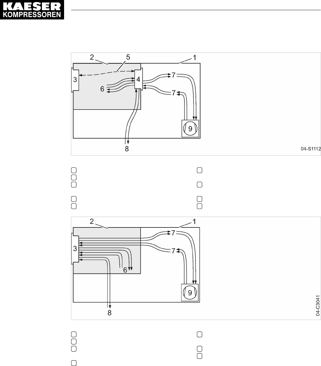
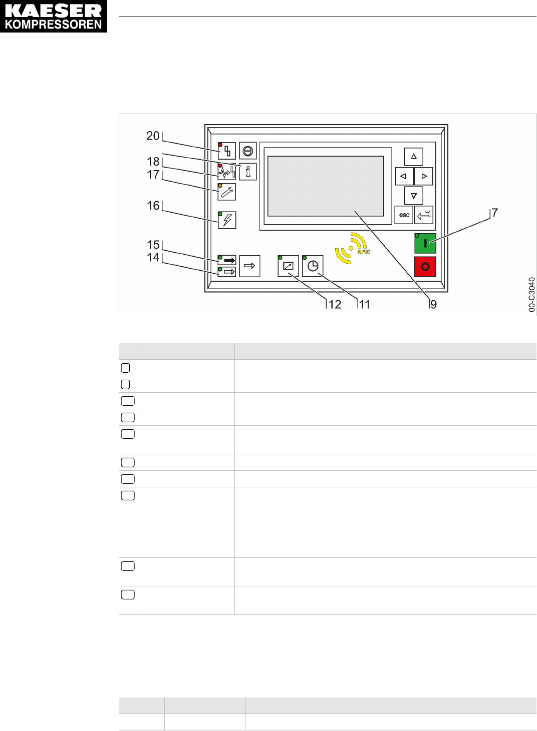
Fig. 5 MCS system design with IOM
1Machine enclosure
2Control cabinet
3SIGMA CONTROL 2 (Prepared for con‐
nection to control center)
4Input-Output-Module (IOM):
5I/O bus
6Inputs/outputs in the interior of the control
cabinet
7Inputs/outputs in the interior of the com‐
pressor
8Inputs/outputs for external sensors
9Compressor
Fig. 6 MCSIO system design
1Machine enclosure
2Control cabinet
3SIGMA CONTROL 2 (Connection to con‐
trol technology not provided)
6Inputs/outputs in the interior of the control
cabinet
7Inputs/outputs in the interior of the com‐
pressor
8Inputs/outputs for external sensors
9Compressor
Function
The control and regulating function allows:
■ Automatic changeover of the machine from LOAD to IDLE or READY.
■ Optimum utilization of the drive motor in relation to the user's actual air demand.
■ Automatic restart of the machine after a power failure (can be deactivated).
5 Design and Function
5.1 The controller
18 User Manual Controller
SIGMA CONTROL 2 SCREW FLUID ≥4.0.X No.: 9_9450 07 USE
The monitoring function allows:
■ Supervision of all maintenance-relevant components via the maintenance interval counters.
■ Display of warning and maintenance messages for due maintenance on the display
of SIGMA CONTROL 2.
The protective function allows:
■ Automatic machine shutdown on alarms that may lead to damage to the machine, e.g. high
current, high pressure or high temperature.
5.2 Operating panel
5.2.1 Indicating and operating elements
Fig. 7 Indicating and operating elements
Item Description Function
1«Up» Scrolls up the menu options. Increases a parameter value.
2«Left» Jumps to the left.
Moves the cursor position to the next left field.
3«Right» Jumps to the right.
Moves the cursor position to the next right field.
4«Down» Scrolls down the menu options.
Reduces a parameter value.
5«Escape» Returns to the next higher menu option level.
Exits the edit mode without saving.
6«Enter» Jumps to the selected menu option.
Exits the edit mode and saves.
7«ON» Switches the machine on.
8«OFF» Switches the machine off.
10 RFID RFID reader for user log-in with RFID Equipment Card.
11 «Timer control» Switches the timer control on and off.
5 Design and Function
5.2 Operating panel
No.: 9_9450 07 USE
User Manual Controller
SIGMA CONTROL 2 SCREW FLUID ≥4.0.X 19
Item Description Function
12 «Remote control» Switches the remote control on and off.
13 «LOAD/IDLE» Toggles between the LOAD and IDLE modes.
19 «Information & Events» Displays the event memory.
21 «Acknowledgement» Confirms/acknowledges alarms and warning messages.
If permissible: Resets the fault counter (RESET).
Tab. 25 Operating elements
5.2.2 Display elements
Fig. 8 Display elements
Item Description Function
7
ON
Continuous green light when the machine switched on.
9
Display
Graphic display with 8 lines and 30 characters per line.
11
Timer control
Continuous green light when the machine is controlled by the timer.
12
Remote control
Continuous green light when the machine is in remote control.
14
IDLE
Continuous green light when the machine is running in IDLE. Flashes
when the «LOAD/IDLE» toggle key is pressed.
15
LOAD
Continuous green light when the machine is running in LOAD.
16
Controller voltage
Continuous green light when voltage is applied to the controller.
17
Warning
Flashes in yellow in the following events:
■ Maintenance necessary
■ Warning message
Continuous yellow light after acknowledgement.
18
Communications
error
Continuous red light to indicate a defective communication connection,
or an external alarm message without machine shutdown.
5 Design and Function
5.2 Operating panel
20 User Manual Controller
SIGMA CONTROL 2 SCREW FLUID ≥4.0.X No.: 9_9450 07 USE
Item Description Function
20
Alarm
Flashes red to indicate a machine alarm.
Continuous red light after acknowledgement.
Tab. 26 Display elements
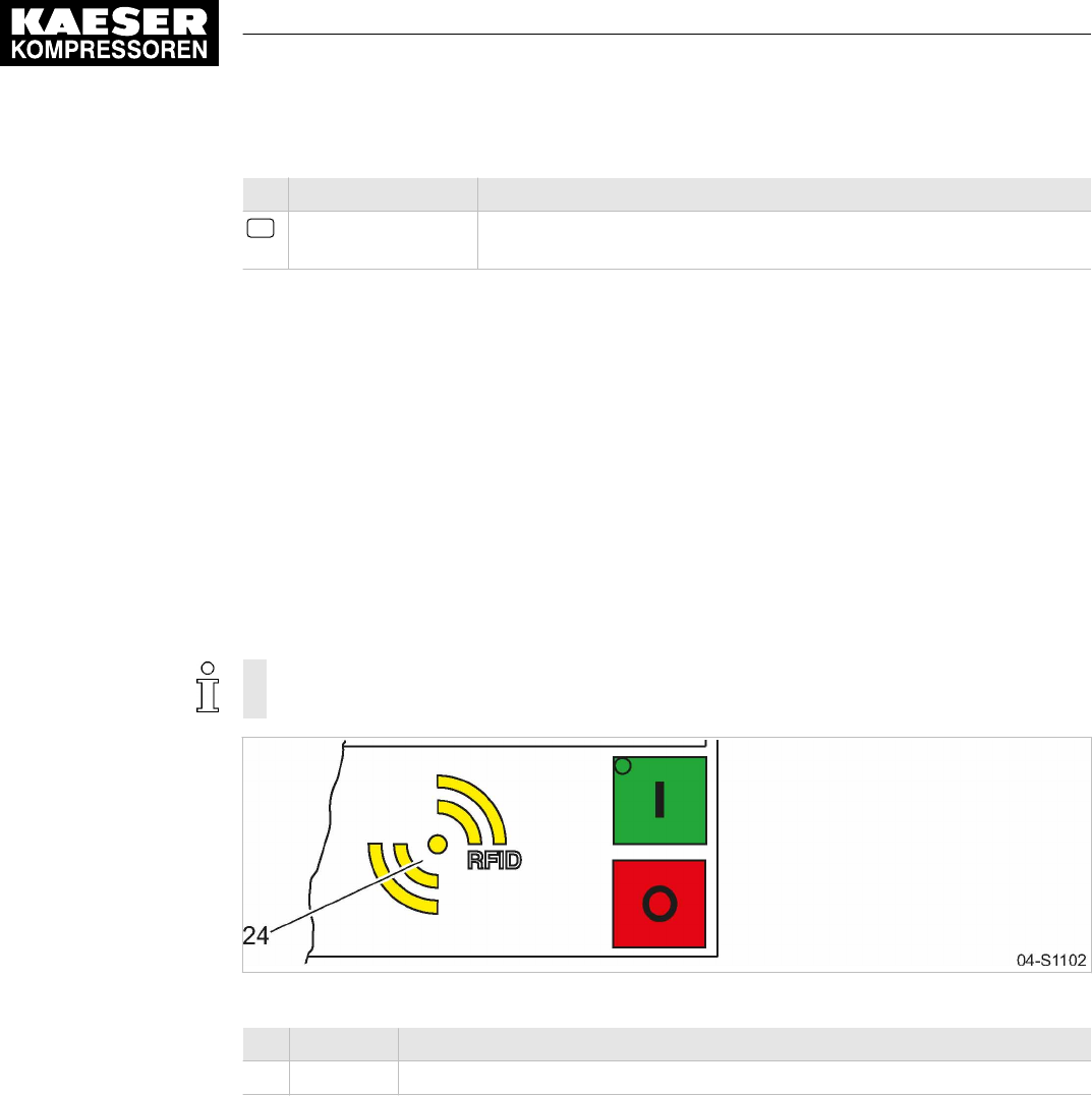
5.2.3 RFID reader
RFID is the abbreviation for “Radio Frequency Identification” and makes possible to identify per‐
sons and objects.
Placing a suitable transponder in front of the RFID reader of the controller will automatically acti‐
vate the communication between transponder and SIGMA CONTROL 2.
A suitable transponder is the RFID Equipment Card. Two of them have been provided with the ma‐
chine.
Typical application:
■ Operators log on at the machine.
(Manual input of the password not required)
The RFID Equipment Cards are carefully packed in a plastic sleeve.
This plastic sleeve is attached to the rear of the controller in the control cabinet.
Fig. 9 RFID reader
Item Description Function
24 RFID RFID reader for the communication with a RFID Equipment Card or RFID Key.
Tab. 27 RFID reader
5.3 Display
Use the display to read information and to enter data. The display comprises 8 lines, each of 30
characters.
During operation, the display will indicate the operating mode.
Pressing «Enter» or one of the arrow keys opens the main menu. Here, you can set the language
to be used for the display of texts or open the various submenus.
5 Design and Function
5.3 Display
No.: 9_9450 07 USE
User Manual Controller
SIGMA CONTROL 2 SCREW FLUID ≥4.0.X 21

5.3.1 Operating mode
88psi 08:15AM 176° F Header
__________________________________
Load Current operating mode
__________________________________
Key – on ¦ pA – on Operating parameters
__________________________________
Run 2500h Load 2490h Operating parameters
Maintenance in 500h Maintenance indicator
Header
The header is the topmost line on the display. It is always shown as white text on a black back‐
ground.
Important information and values are displayed in the header.
The displayed data varies depending on the machine type:
Type Header, left Header, center Header, right
SIGMA CONTROL 2
FLUID
Working pressure Time Airend discharge temperature
SIGMA CONTROL 2
DRY
Working pressure Time Airend discharge temperature
SIGMA CONTROL 2
VAC
Working pressure Time Airend discharge temperature
SIGMA CONTROL 2
BOOSTER
Pressure at the com‐
pressed air inlet p1
Temperature at the
compressed air
outlet T2
Pressure at the compressed
air outlet p4
Tab. 28 Header
Lines 3 and 5: Operational state
Depending on the settings, either the current state of the machine or a menu text is shown in line 3.
The following parameters with their current values are displayed in line 5:
■ Remote control yes/no
■ Timer control yes/no
■ Pressure control
Lines 7 and 8: Machine state
The following parameters with their current values are displayed in lines 7 and 8:
■ The hours during which the machine was activated.
■ The hours during which the machine ran in operating mode LOAD.
■ Remaining working hours of the machine before the next maintenance.
5 Design and Function
5.3 Display
22 User Manual Controller
SIGMA CONTROL 2 SCREW FLUID ≥4.0.X No.: 9_9450 07 USE

5.3.2 Main menu
88psi 08:15AM 176° F
Main menu
----------------English US---------------- Language
▶1 Status Active line
▶2 Performance data Submenu
▶3 Operating data Submenu
▶4 Maintenance Submenu
▶5 Configuration Submenu
Description
The main menu is the top menu level. You open the individual submenus in the main menu.
A scrollbar appears at the right side of the display if you open a menu with more than 6 lines. It
represents the currently visible portion of the menu. A short scrollbar thus indicates that the opened
menu is very long as only a small portion can be displayed.
The image above provides an example for the appearance of the main menu (without scrollbar).
Numbering
Each menu is numbered.
Not all menus may be displayed because the access to certain menus is restricted by the access
level, and some menus are displayed or hidden due to specific settings or options.
For example, you can recognize subordinate menus in the menu structure by the number preced‐
ing their designation. The menu structure is explained in chapter 5.6.2.
Active line
The active line is always shown as white text on a dark background. Do not confuse this with the
header which is also shown with white lettering on a black background.
Press «Enter» to open a menu in the active line. This opens the selected menu.
Here, you can change parameters.
5.3.3 Setting parameters
In order to set a parameter in the active line of the selected menu, you must always switch to
setting mode.
Changing parameters
Press «Enter». The value of the parameter will flash indicating that it can be changed.
The «Enter» key affects only the active line.
In some lines, you can change more than a single parameter.
In this case, you must first select the specific parameter with the «Left» or «Right» keys.
5 Design and Function
5.3 Display
No.: 9_9450 07 USE
User Manual Controller
SIGMA CONTROL 2 SCREW FLUID ≥4.0.X 23

Resetting current parameters
In order to reset current parameters to zero, activate the check box for
Reset
in the active line of
the display.
First, press «Enter» to switch into setting mode. The check box
Reset
will flash.
You then press «Up». The check box is activated and flashes.
Press «Enter» to save the settings.
The parameters no longer flash and are reset. The check box for
Reset
is again deactivated.
Check box
Reset
Status
☒ activated
☐ deactivated
Tab. 29 Reset check box status
5.3.4 Activating keys with check boxes
Certain keys of the SIGMA CONTROL 2 are locked by default. Activate the corresponding check
boxes in the active line of the display to unlock these keys.
First, press «Enter» to switch into setting mode. The check box will flash.
You then press «Up». The check box is activated and flashes.
Press «Enter» again to save the settings.
The display line no longer flashes and the key is activated.
Proceed correspondingly to deactivate a key.
Check box Status
☑ activated
☐ deactivated
Tab. 30 Check box status
5.4 Access rights
Access to the controller is governed by the user name combined with a password.
Users log on using an RFID Equipment Card by default. Alternatively, you can manually enter the
user name and the password.
When the controller is switched on, the lowest level of access (level 0) is activated.
You have access to a further level: Access level 2
Access level 2 allows you to display and adjust further parameters.
The access level will automatically return to level 0 after 10 minutes without any key being pressed.
Secure storage of the RFID Equipment Cards
You will receive 2 RFID Equipment Cards with each machine.
They are stored in a plastic sleeve.
This plastic sleeve is attached at the rear of the controller in the control cabinet.
If you lose both RFID Equipment Cards, you can register a new RFID Equipment Card only after
having entered the user name and the password. A new RFID Equipment Card may be registered
by KAESER service subject to a fee, if the user name and the password are lost.
5 Design and Function
5.4 Access rights
24 User Manual Controller
SIGMA CONTROL 2 SCREW FLUID ≥4.0.X No.: 9_9450 07 USE

5.5 KAESER CONNECT
Using an Internet-capable device with web browser, you can open a visualization of the controller.
This enables remote checking of, for example, the operating and energy efficiency of your ma‐
chine. For this purpose, you must once generate a password (see Chapter 8.2.5). KAESER
CONNECT does not require additional software to do so. The display language of KAESER
CONNECT can be set independently to the language used with SIGMA CONTROL 2.
Fig. 10 KAESER CONNECT for SIGMA CONTROL 2
KAESER CONNECT functions:
Operating element Meaning
read => write Switching from read-only to read/write mode
To create users and acknowledge messages
write => read Switching from read/write to read-only mode
Logout User log-out
Contact/Service Displaying the contact information for an authorized KAESER service repre‐
sentative
Select language: Setting the display language for KAESER CONNECT
System status Mapping of the local menu
Graphs ■ Pressures and temperatures are displayed in different graphs
■ Graphic representation of the machine status (STOP, IDLE, LOAD) and
RPM along the time axis
Messages ■ Current messages
■ Message history (event memory)
I/O display Assignment of the input/output modules
5 Design and Function
5.5 KAESER CONNECT
No.: 9_9450 07 USE
User Manual Controller
SIGMA CONTROL 2 SCREW FLUID ≥4.0.X 25

Operating element Meaning
User management ■ Creating and activating new user accounts
■ Modifying or deactivating existing user accounts
■ Changing passwords
Settings ■ Unit display format
■ Date display format
■ Time display format
Backup Saving the SIGMA CONTROL 2 data to a PC
Tab. 31 KAESER CONNECT functions
Further information For opening KAESER CONNECT, login and other procedures, please see chapter 8.3.
5.6 Menus – overview
5.6.1 Operating mode
When the machine is switched on, details of the software are displayed, for example:
Compressor Machine model
PN: SN: Part number and serial number of the machine
EN: Equipment number of the machine
SIGMA CONTROL 2 – MCS MCS: Main Control System
PN: SN: Part number and serial number of the controller
Software: Software version
Subsequently, the software is loaded and the current operating mode is displayed, for example:
88psi 08:15AM 176° F Header
__________________________________
Load Current operating mode
__________________________________
Key – on ¦ pA – on Operating parameters
__________________________________
Run 2500h Load 2490h Operating parameters
Maintenance in 500h Maintenance indicator
The following parameters are displayed:
■ Current operating mode of the machine
■ On the left-hand side of "¦" you can see from where the compressor is switched on (in the illus‐
trated example via the green «ON» key) and what the current status is (in the example "on").
■ On the right-hand side of "¦", you can see the mode of the load control (in the illustrated exam‐
ple, the network nominal pressure pA is active) and the mode of the compressor (in the exam‐
ple it is switched on).
■ Number of operating hours and hours of the machine being in LOAD mode.
5 Design and Function
5.6 Menus – overview
26 User Manual Controller
SIGMA CONTROL 2 SCREW FLUID ≥4.0.X No.: 9_9450 07 USE

5.6.2 Menu structure
Press «Enter» or one of the arrow keys to open the main menu.
In the main menu, you can:
■ Retrieve displayed information
■ Enter customer-specific settings
The menus shown require password access level 2.
Main menu
Navigation Function/Submenu
1 Status ■ Messages
■ Statistics
■ Current pressure control
■ Current operating mode
■ DI/DO status
■ pN/ADT curve
■pN/n curve 1)
For details of the
Status
menu, please see ta‐
ble 33.
1) Power switching with frequency converter
3) SIGMA CONTROL 2 (Prepared for connection to control technology)
5 Design and Function
5.6 Menus – overview
No.: 9_9450 07 USE
User Manual Controller
SIGMA CONTROL 2 SCREW FLUID ≥4.0.X 27

Navigation Function/Submenu
2 Performance data ■ Compressor
─ System pressure pNloc
─ Internal pressure pi
─ ADT
─ Oil separator
─ Starting temperature
─ Inlet temperature
─ PD temperature
─ Air filter
■ Compressor motor
─ Motor temperature (if available)
─Speed 1)
─Current 1)
─UzK 1)
─Torque 1)
■ Fan
─Speed 1)
─Current 1)
─UzK 1)
─Torque 1)
■ Analogue values
■ SIGMA CONTROL 2
3 Operating data ■ Operating hours
─ Compressor
─ On load
─ Motor
─ Compressor block
─ SIGMA CONTROL 2
─ Partial load valves
■ Switching cycles
─ Load valve on
─ Mains contactor on
■ kWh counter
1) Power switching with frequency converter
3) SIGMA CONTROL 2 (Prepared for connection to control technology)
5 Design and Function
5.6 Menus – overview
28 User Manual Controller
SIGMA CONTROL 2 SCREW FLUID ≥4.0.X No.: 9_9450 07 USE

Navigation Function/Submenu
4 Maintenance Oil filter
Oil separator
Oil change
Air filter
Valve inspection
Belt/coupling inspection
Compressor motor
Bearing lube
Bearing change
Fan motor(s)
Bearing lube
Bearing change
Electrical equipment
Annual maintenance due
5 Configuration For details of the
Configuration
menu, please
see table 34.
6 Compressor clock Key clock
Reset
Switching point 01:
Switching point 02:
Switching point 03:
Switching point 04:
Switching point 05:
Switching point 06:
Switching point 07:
Switching point 08:
Switching point 09:
Switching point 10:
7 User Name
Password
Current access level:
8 Communication ■ Ethernet/SIGMA NETWORK
■Com-Module 3)
Key remote
For details of the
Communication
menu, please
see table 37.
9 Machine test ■ TÜV inspection
1) Power switching with frequency converter
3) SIGMA CONTROL 2 (Prepared for connection to control technology)
5 Design and Function
5.6 Menus – overview
No.: 9_9450 07 USE
User Manual Controller
SIGMA CONTROL 2 SCREW FLUID ≥4.0.X 29

Navigation Function/Submenu
10 Components ■ Compressor motor
─ Power switching
For details of the
Components
menu, please
see table 39.
1) Power switching with frequency converter
3) SIGMA CONTROL 2 (Prepared for connection to control technology)
Tab. 32 Menu structure
5.6.2.1
Status
menu
Navigation Function/Submenu
1.1 Messages ■ Current messages
■ Message history
─ Compressor messages
─ Diagnostic messages
─ System messages
■ Address error
─Incorrect parameterisation in 2)
Status report
current Alarms
current Warnings
1.2 Statistics Load (hours)
since/Reset:
Load (speed) 1)
since/Reset:
Network actual pressure pNloc
Motor starts
since/Reset:
Motor starts /d
Motor starts /h
Motor starts T↓
Last load run
Last idle run
Last motor off
1) Power switching with frequency converter
2) Only visible in the event of parameterization error
3) SIGMA CONTROL 2 (Prepared for connection to control technology)
5 Design and Function
5.6 Menus – overview
30 User Manual Controller
SIGMA CONTROL 2 SCREW FLUID ≥4.0.X No.: 9_9450 07 USE

Navigation Function/Submenu
1.3 Current pressure control SIGMA CONTROL 2
Cut-out pressure
SP/SD
Network actual pressure
Frequency converter 1)
Setpoint pressure 1)
Actual pressure 1)
Speed nominal value 1)
Speed actual value 1)
Speed limits 1)
1.4 Current operating mode Compressor on
Load control
Control mode
Idle period
Acknowledgement
Waste heat recovery (if available)
1.5 DI/DO status 1st I/O module
DI/DO display
2nd I/O module
DI/DO display
3rd I/O module
DI/DO display
1.6 pN/ADT curve Diagram:
Nominal pressure/Discharge temperature
1.7 pN/n curve 1) Diagram:
Nominal pressure/Speed
1) Power switching with frequency converter
2) Only visible in the event of parameterization error
3) SIGMA CONTROL 2 (Prepared for connection to control technology)
Tab. 33
Status
menu
5 Design and Function
5.6 Menus – overview
No.: 9_9450 07 USE
User Manual Controller
SIGMA CONTROL 2 SCREW FLUID ≥4.0.X 31

5.6.2.2
Configuration
menu
Navigation Function/Submenu
5.1 General ■ System information
─SIGMA CONTROL 2 MCS 3)
─ Software
─ KAESER:PN/SN
─ Controller manufacturer:PN/SN
─ MFGDT (Manufacturing date)
─ Compressor
─ EN (Equipment number)
─ PN (Part number)
─ SN ( Serial number)
─ I/O modules
─ First IOM
─Second IOM (if available) 3)
─FC information 1)
─ Compressor motor
─ Oil-/air cooler fan
─ Oil cooler fan
Model:
Date/time
Time zone
■ Time server
─ active:
─ IP address
Date format
Time format
Pressure unit
Temperature unit
Display lighting
5.2 Pressure control ■ Pressure sensors
■ Pressure settings
■ Load control
■ Network actual pressure
For details of the
Pressure control
menu, please
see table 35.
1) Power switching with frequency converter
3) SIGMA CONTROL 2 (Prepared for connection to control technology)
5 Design and Function
5.6 Menus – overview
32 User Manual Controller
SIGMA CONTROL 2 SCREW FLUID ≥4.0.X No.: 9_9450 07 USE

Navigation Function/Submenu
5.3 Control mode Local mode:
■ Venting period
■ DUAL
■ QUADRO
■ Partial load valves
5.4 Compressor start ■ Compressor on
■ Compressor off
Autostart:
Start inhibit:
Starting temperature
5.5 Acknowledgement Remote mode:
RC ack
Key remote
5.6 ETM Waste heat recovery
Local mode:
Remote mode:
current
RC DI
Key remote
■ Oil cooler
■ Waste heat recovery
5.7 I/O periphery ■ DO functions
■ Analogue values
■ External messages
■ Switch
For details of the
I/O periphery
menu, please
see table 36.
5.8 Timer on
off
DOR
1) Power switching with frequency converter
3) SIGMA CONTROL 2 (Prepared for connection to control technology)
5 Design and Function
5.6 Menus – overview
No.: 9_9450 07 USE
User Manual Controller
SIGMA CONTROL 2 SCREW FLUID ≥4.0.X 33

Navigation Function/Submenu
5.9 Refrigeration dryer (if available) Control mode
Compressor ready:
Compressor Clk/RC/RB off:
Temperature ↑
DOR
DOT
Temperature ⇟
DOR
DOT
Safe compressed air supply/Safe compressed
air quality
Error operation without RD
active:
Run time max.:
Reset Alarm:
1) Power switching with frequency converter
3) SIGMA CONTROL 2 (Prepared for connection to control technology)
Tab. 34
Configuration
menu
Pressure control
menu
Navigation Function/Submenu
5.2.1 Pressure sensors System pressure pNloc
Internal pressure pi
5.2.2 Pressure settings pRV (Safety relief valve opening pressure)
Pressure rise
pE SP/SD
ΔpFC 1)
Nominal pressure
Setpoint pressure
pA SP/SD
pB SP/SD
System pressure low
Cut-in pressure min
1) Power switching with frequency converter
5 Design and Function
5.6 Menus – overview
34 User Manual Controller
SIGMA CONTROL 2 SCREW FLUID ≥4.0.X No.: 9_9450 07 USE

Navigation Function/Submenu
5.2.3 Load control ■ pA/pB Clock
(Menu see Remote mode)
Local mode
Remote mode
pA/pB Cycle
pA/pB RC
pA/pB DO
Load RC
loc.-load RC
Key remote
Key idle
5.2.4 Network actual pressure pNloc (locale network pressure)/FC USS 1)/AII
AII
For sensor error:
Type of message:
Warning
Alarm
1) Power switching with frequency converter
Tab. 35
Pressure control
menu
5 Design and Function
5.6 Menus – overview
No.: 9_9450 07 USE
User Manual Controller
SIGMA CONTROL 2 SCREW FLUID ≥4.0.X 35

I/O periphery
menu
Navigation Function/Submenu
5.7.1 DO functions Controller on
DOR
DOT
Compressor on
DOR
DOT
Motor running
DOR
DOT
Idle
DOR
DOT
On load
DOR
DOT
Group alarm
DOR
DOT
Group warning
DOR
DOT
Remote mode
DOR
DOT
Clock active
DOR
DOT
■ Clock contact
DOR
DOT
EMERGENCY STOP
DOR
DOT
1) Power switching with frequency converter
5 Design and Function
5.6 Menus – overview
36 User Manual Controller
SIGMA CONTROL 2 SCREW FLUID ≥4.0.X No.: 9_9450 07 USE

Navigation Function/Submenu
5.7.2 Analogue values ■ AnMod (Analog modules)
─ AnMod_p_1
─ AnMod_p_2
─ AnMod_p_3
─ AnMod_p_4
─ AnMod_T_1
─ AnMod_T_2
─ AnMod_T_3
─ AnMod_T_4
─ AnMod_I_1
─ AnMod_I_2
■ AI (Analog inputs)
─ AI_p_1
─ AI_p_2
─ AI_T_1
─ AI_T_2
─ AI_I_1
─ AI_I_1
■ AO (Analog outputs)
─ AO_p_1
─ AO_p_2
─ AO_T_1
─ AO_T_2
─ AO_I_1
─ AO_I_2
─AO_n_1 1)
■ PD (Process data)
─ PD_p_1
─ PD_p_2
─ PD_T_1
─ PD_T_2
─ PD_I_1
─ PD_I_2
5.7.3 External messages ■ External message 1
■ External message 2
■ External message 3
■ External message 4
■ External message 5
■ External message 6
1) Power switching with frequency converter
5 Design and Function
5.6 Menus – overview
No.: 9_9450 07 USE
User Manual Controller
SIGMA CONTROL 2 SCREW FLUID ≥4.0.X 37

Navigation Function/Submenu
5.7.4 Switch ■ System pressure pNloc
■ Internal pressure pi
■ ADT
■ Inlet temperature
■ PD temperature
1) Power switching with frequency converter
Tab. 36
I/O periphery
menu
5.6.2.3
Communication
menu
Navigation Function/Submenu
8.1 Ethernet/SIGMA NETWORK ■ IP configuration
─ IP address
─ Subnet mask
─ Gateway
─ DNS Server 1
─ DNS Server 2
─ Restart network
■ Connections
─ SIGMA CONTROL 2
─ SAM 4.0
Restart
Timeout
Cycle time
For details of the
Connections
menu, please see
table 38.
■ E-mail
─ active:
Compressor number:
Language:
Repeat cut-off time:
─ Sender address:
Sender name:
Contact telephone:
Receiver address:
─ SMTP Server:
User name:
Password:
─ Port/Timeout
Resend after:
MAC: MAC address
3) SIGMA CONTROL 2 (Prepared for connection to control technology)
5 Design and Function
5.6 Menus – overview
38 User Manual Controller
SIGMA CONTROL 2 SCREW FLUID ≥4.0.X No.: 9_9450 07 USE

Navigation Function/Submenu
8.2 Com-Module 3) The content of the menu depends on the type of
the communication module identified.
The following KAESER communications mod‐
ules may be used:
■ PROFIBUS
■ Modbus
■ Modbus TCP
■ DeviceNet
■ PROFINET
3) SIGMA CONTROL 2 (Prepared for connection to control technology)
Tab. 37
Communication
menu
5.6.2.4
Connections
menu
Navigation Function/Submenu
8.1.2 Connections ■ SIGMA CONTROL 2
─ Status
─ Mode
─ Port
─ Communication partner
─ IP address
─ Communication error
Start td
Timeout
■ SAM 4.0
─ Status
─ SAM 4.0 active:
Send/receive
Send
─ IP address
─ Port
─ Communication error
Start td
Timeout
Restart
Timeout
Cycle time
Tab. 38
Connections
menu
5 Design and Function
5.6 Menus – overview
No.: 9_9450 07 USE
User Manual Controller
SIGMA CONTROL 2 SCREW FLUID ≥4.0.X 39

5.6.2.5
Components
menu
Navigation Function/Submenu
10.1 Compressor motor USS status: Run/Error
■ Power switching
─ Star-delta start
─ DOL start
─High-voltage cell 3)
─SFC USS 1)
─Softstart 3)
─Customer-provided 3)
For details of the
Power switching
menu, please
see table 40.
1) Power switching with frequency converter
3) SIGMA CONTROL 2 (Prepared for connection to control technology)
Tab. 39
Components
menu
5 Design and Function
5.6 Menus – overview
40 User Manual Controller
SIGMA CONTROL 2 SCREW FLUID ≥4.0.X No.: 9_9450 07 USE

5.6.2.6
Power switching
menu
Navigation Function/Submenu
10.1.1 Power switching ■ Star-delta start
─ Temp. warm start
─ Star time T↑
─ Star time T↓
─ Υ/Δ switching time
─ Overload relay
─ Mains contactor
─ Star contactor
─ Delta contactor
■ DOL start
─ Run-up period:
─ Overload relay
─ Mains contactor
─ Delta contactor
■High-voltage cell 3)
─ Run-up period:
─ Overload relay
─ Mains contactor
■SFC USS 1)
USS status: Run/Error
─ Run-up period:
─ Service operation
─ Heavy load monitoring
─ Mains contactor
─ STO channel A
─ STO channel B
■Softstart 3)
─ ready
─ Motor running
─ Start-up ended
─ Start
─ Reset
─ Mains contactor
■Customer-provided 3)
─ Temp. warm start
─ Run-up period T↑
─ Run-up period T↓
─ ready
─ Mains contactor/Alarm td
─ Redundancy contactor/Alarm td
1) Power switching with frequency converter
3) SIGMA CONTROL 2 (Prepared for connection to control technology)
5 Design and Function
5.6 Menus – overview
No.: 9_9450 07 USE
User Manual Controller
SIGMA CONTROL 2 SCREW FLUID ≥4.0.X 41

10.1.1 Power switching If there is a power switching unit with a frequen‐
cy converter, the further content of the menu is
determined by the type of frequency converter
and the settings available for it.
Tab. 40
Power switching
menu
5.7 Operating modes and control modes
5.7.1 Operating modes
STOP
The machine is connected to the power supply.
The
Controller voltage
LED lights green.
The machine is switched off. The
On
LED is extinguished.
READY
The machine has been activated with the «ON» key:
■ The
On
LED lights green.
■ The drive motor is stopped.
■ The inlet valve is closed.
■ The minimum pressure check valve isolates the oil separator tank from the air system.
■ The venting valve is open.
The compressor motor starts as soon as system pressure is lower than the network nominal pres‐
sure (cut-off pressure).
In addition, timing and/or remote control may affect the start of the motor.
LOAD
The compressor motor runs under load.
■ The inlet valve is open.
■ The airend delivers compressed air to the air system.
IDLE
The compressor motor runs unloaded with low power consumption.
■ The inlet valve is closed.
■ The minimum pressure check valve isolates the oil separator tank from the air system.
■ The venting valve is open.
A small volume of air circulates through the bleed hole in the inlet valve, through the airend and
back to the inlet valve via the venting line.
5 Design and Function
5.7 Operating modes and control modes
42 User Manual Controller
SIGMA CONTROL 2 SCREW FLUID ≥4.0.X No.: 9_9450 07 USE

5.7.2 Control modes
Using the selected control mode, the controller switches the machine between its various opera‐
tional states in order to compensate for air being drawn off by consumers, and to maintain the sys‐
tem pressure between the set minimum and maximum values. The control mode also rules the de‐
gree of energy efficiency of the machine.
The machine-dependant venting phase between the LOAD and READY operating modes ensures
load changes at minimum material stresses.
The controller SIGMA CONTROL 2 can operate in the following modes:
■ DUAL
■ QUADRO
■ VARIO
■ CONTINUOUS
■ DYNAMIC
■ MODULATING control
DUAL
In the DUAL control mode, the machine is switched back and forth between LOAD and IDLE to
maintain the machine working pressure between the preset minimum and maximum values. When
maximum pressure is reached, the machine switches to IDLE. When the preset
idling time
has
elapsed, the machine switches to READY.
The
idling time
is factory preset according to the maximum starting frequency of the compressor
motor. The shorter the
idling time
setting, the sooner (and more frequently) the drive motor is stop‐
ped.
QUADRO
Unlike the DUAL regulating mode, the machine will switch from LOAD to READY in QUADRO
mode after periods with low compressed air consumption.
After periods with a high compressed air consumption, the machine will switch from LOAD to
READY after passing through IDLE.
In this control mode, the controller requires two specified times: The
running time
and the
idling/
standstill time
.
The shorter these times are set, the sooner (and more frequently) the motor is stopped.
VARIO
The VARIO mode is based on the DUAL control mode. Unlike the DUAL regulating mode, the
idling time
is automatically lengthened or shortened to compensate for higher or lower machine
starting frequencies.
CONTINUOUS
Unlike the DUAL control mode, the machine is switched back and forth between LOAD and IDLE,
to maintain the machine working pressure between the preset minimum and maximum values.
When maximum pressure is reached, the machine switches to IDLE. However, the machine does
not switch to READY.
5 Design and Function
5.7 Operating modes and control modes
No.: 9_9450 07 USE
User Manual Controller
SIGMA CONTROL 2 SCREW FLUID ≥4.0.X 43
Option C1

DYNAMIC
Unlike the DUAL regulating mode, the machine will switch from LOAD to READY in DYNAMIC
mode at low drive motor temperature.
And from LOAD via IDLE to READY at a high drive motor temperature.
The lower the drive motor temperature, the sooner (and, therefore, more often and longer) it is
stopped.
MODULATING control
The MODULATING control is an additional mechanical regulation. It continuously changes the de‐
livery volume within the machine's control range.
A control valve, the proportional controller, changes the degree of opening of the inlet valve when
the machine transports compressed air into the air network (LOAD).
The load and power consumption of the drive motor rises and falls with the air demand.
5.7.3 Frequency-controlled drive (SFC)
If the machine runs in LOAD , the frequency converter compares the ACTUAL value with the TAR‐
GET value of the system pressure and regulates, depending on the difference, the speed of the
compressor motor and the airend.
The speed of the airend determines the rate of compressed air delivery and the working pressure.
If air consumption rises, the frequency converter increases motor speed and therefore increases
the volume of air delivered.
If air consumption drops, the converter reduces motor speed and therefore reduces the volume of
air delivered.
The network pressure remains constant – within the control range of the converter – regardless of
fluctuating air demand.
If the network pressure exceeds the TARGET value:
Outside the frequency converter's range of control the machine reverts to the selected control
mode.
DUAL:
The minimum controllable speed is reached and the machine switches to IDLE . The drive motor
runs unloaded with low power consumption.
When the preset idling time has elapsed, the machine switches to READY.
VARIO/QUADRO/CONTINUOUS:
The minimum controllable speed is reached and, depending on the air demand at the time, the ma‐
chine switches either to READY or to IDLE. The machine remains in IDLE at least for the duration
of the
venting time
, before it switches to READY.
DYNAMIC:
The minimum controllable speed is reached and, depending on the air temperature of the drive mo‐
tor the machine switches either to READY or to IDLE. The machine remains in IDLE at least for the
duration of the
venting time
, before it switches to READY.
If the network pressure falls below the TARGET value:
The frequency converter runs the motor up to a speed at which air delivery matches the air de‐
mand.
5 Design and Function
5.7 Operating modes and control modes
44 User Manual Controller
SIGMA CONTROL 2 SCREW FLUID ≥4.0.X No.: 9_9450 07 USE
Option C1

The inlet valve opens and the machine delivers compressed air.
The frequency converter varies the speed of the drive motor according to the air demand. The
power consumption of the drive motor rises and falls according to air demand.
5.7.4 MODULATING control
With the help of a mechanical control valve (the proportional controller), the opening and closing of
the inlet valve is continuously varied in relation to the actual air demand. The airend delivers com‐
pressed air to the distribution network.
The load and power consumption of the drive motor rises and falls with the air demand.
To ensure optimal control on large compressors, the control air for the proportional controller is tak‐
en from an external air receiver.
5 Design and Function
5.7 Operating modes and control modes
No.: 9_9450 07 USE
User Manual Controller
SIGMA CONTROL 2 SCREW FLUID ≥4.0.X 45

6 Installation and Operating Conditions
6.1 Maintaining ambient conditions
➤ Follow the instructions in the machine's operator manual.
6.2 Installation conditions
The installation and operating conditions depend the machine into which the controller is installed.
UV radiation!
Direct sunlight (UV radiation) can destroy the display screen.
➤ Do not allow the display screen to be subjected to direct sunlight.
➤ See the machine's operator manual for required conditions.
6 Installation and Operating Conditions
6.1 Maintaining ambient conditions
46 User Manual Controller
SIGMA CONTROL 2 SCREW FLUID ≥4.0.X No.: 9_9450 07 USE

7 Installation
7.1 Reporting Transport Damage
1. Check the machine for visible and hidden transport damage.
2. Inform the carrier and the manufacturer in writing of any damage without delay.
7.2 Machine identification
If the machine is run in sequenced operation its identification as detailed in the installation diagram
is to be taken into account.
Identifying the machine for operation in remote mode.
➤ Attach the following notice to warn of remote machine operation (suggestion):
Remote control: danger of unexpected starting!
➤ Make sure the power supply disconnecting device is switched off before commencing any
work on the machine.
Tab. 41 Machine identification
➤ Label the starting device in the remote control center as follows (suggestions):
Remote control: danger of unexpected starting!
➤ Before starting, make sure that no one is working on the machine and that it can be safely
started.
Tab. 42 Remote control identification
Identifying the machine for clock control mode operation
➤ Attach the following notice to warn of remote machine operation (suggestion):
Clock control: Risk of injury caused by unexpected starting!
➤ Make sure the power supply disconnecting device is switched off before commencing any
work on the machine.
Tab. 43 Machine identification
7 Installation
7.1 Reporting Transport Damage
No.: 9_9450 07 USE
User Manual Controller
SIGMA CONTROL 2 SCREW FLUID ≥4.0.X 47

8 Initial Start-up
8.1 Outline
SIGMA CONTROL 2 was designed and developed for a number of applications. Potential settings
are correspondingly varied.
It is possible that only a few of these settings are needed for the initial start-up. This depends on
the application .
The following sections explain the large number of practical applications, but only one configuration
is relevant for a specific use.
8.2: Configuring the controller (display format, units, languages, etc.)
8.3: Using KAESER CONNECT
8.4: Pressure parameters of the machine
8.5: Machine start and stop
8.6: Control modes
8.7: Electronic Thermal Management
8.8: Refrigerated dryer
8.9: Configuring the machine for local mode
8.10: Configuring the machine for master control operation
8.11: Configuring input and output signals
8.12: Activating remote acknowledgement
8.13: Linking to an external pressure transducer
8.14: Commissioning the machine
8.2 Configuring the controller
The following chapters describe in detail the basic settings for the SIGMA CONTROL 2. The
quick installation guide at the beginning of this operating manual provides an overview of the
essential displays and operating elements, the main menu and important functions.
8 Initial Start-up
8.1 Outline
48 User Manual Controller
SIGMA CONTROL 2 SCREW FLUID ≥4.0.X No.: 9_9450 07 USE

➤ Carry out settings as required:
■ 8.2.1: Selecting menu options (introduction)
■ 8.2.2: Setting the language
■ 8.2.3: Noting number of the KAESER Equipment Card
■ 8.2.4: User log-in with RFID Equipment Card
■ 8.2.5: Generating a password
■ 8.2.6: Manual user log-in
■ 8.2.7: Checking and setting time and date
■ 8.2.8: Setting the time zone (summer and winter time)
■ 8.2.9: Setting display formats (date, time, units of pressure and temperature)
■ 8.2.10: Setting the display illumination
■ 8.2.11: Setting the contrast and the brightness
■ 8.2.12: Activating the remote control
■ 8.2.13: IP configuration
■ 8.2.14: Configuring the e-mail function
■ 8.2.15: Setting the time server
■ 8.3.6: Creating a user account
8.2.1 Selecting menu options
All menu options can be selected with the «Down», «Up» and «Enter» keys.
Example: Selecting the < Configuration – General > menu
1. Switch on the machine and wait for SIGMA CONTROL 2 to start.
The operating mode is displayed.
88psi 08:15AM 176° F Header
__________________________________
Load Current operating mode
__________________________________
Key – on ¦ pA – on Operating parameters
__________________________________
Run 2500h Load 2490h Operating parameters
Maintenance
in 500h
Maintenance indicator
8 Initial Start-up
8.2 Configuring the controller
No.: 9_9450 07 USE
User Manual Controller
SIGMA CONTROL 2 SCREW FLUID ≥4.0.X 49

2. Press «Enter».
The main menu is displayed.
88psi 08:15AM 176° F
Main menu
----------------English US---------------- Current language
▶1 Status Submenu
▶2 Performance data Submenu
▶3 Operating data Submenu
▶4 Maintenance Submenu
▶5 Configuration Active line
3. Use «Up» or «Down» to select the
Configuration
line.
4. Press «Enter».
The
Configuration
menu is displayed.
5. Use «Up» or «Down» to select the
General
line.
6. Press «Enter».
The
General
menu is displayed.
88psi 08:15AM 176° F
5.1 General Menu
▶1 System information Submenu
·········
Model: XXXXXX Set machine type (SC2 FLUID)
·········
Date/time
04/13/16 08:15:37AM Current date and time
7. Use «Up» or «Down» to select a menu item in the
General
submenu such as
System
information
.
8. Press «Escape» repeatedly to leave this menu.
8.2.2 Setting the language
The controller can display text messages in the following languages:
Arabic Estonian Italian Norwegian Spanish
Bulgarian Finnish Japanese Polish Spanish
(South America)
Chinese French Korean Portuguese Czech
Danish French
(Canada)
Croatian Romanian Turkish
German Greek Latvian Russian Hungarian
English Hebrew Lithuanian Swedish ...
English (USA) Indonesian Dutch Slovenian ...
Tab. 44 Display languages
8 Initial Start-up
8.2 Configuring the controller
50 User Manual Controller
SIGMA CONTROL 2 SCREW FLUID ≥4.0.X No.: 9_9450 07 USE
Some of the units, as well as clock and date format, will be adjusted according to the lan‐
guage selected. You can manually change these settings (see chapter 8.2.9).
Precondition The operating mode is displayed.
1. Press «Enter».
The main menu is displayed.
88psi 08:15AM 176° F
Main menu
----------------English US---------------- Current language
▶1 Status Active line
▶2 Performance data Submenu
▶3 Operating data Submenu
▶4 Maintenance Submenu
▶5 Configuration Submenu
2. Press the «Up» key.
The currently set language is displayed as the active line.
88psi 08:15AM 176° F
Main menu
----------------English US---------------- Active line with currently set language
▶1 Status Submenu
▶2 Performance data Submenu
▶3 Operating data Submenu
▶4 Maintenance Submenu
▶5 Configuration Submenu
3. Press «Enter».
The currently set language flashes.
4. Use «Up» or «Down» to select the desired language.
5. Press «Enter».
Result The user interface is displayed in the set language.
8.2.3 Noting the number of the KAESER Equipment Card
The number of your KAESER Equipment Card is identical with the
user name
displayed on
SIGMA CONTROL 2 after you have successfully logged on using your KAESER Equip‐
ment Card.
8 Initial Start-up
8.2 Configuring the controller
No.: 9_9450 07 USE
User Manual Controller
SIGMA CONTROL 2 SCREW FLUID ≥4.0.X 51
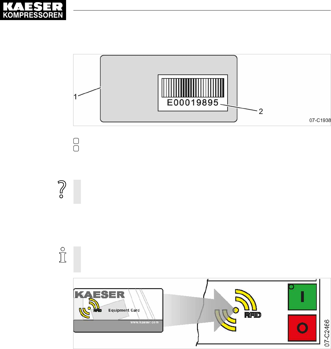
Fig. 11 Back of the KAESER Equipment Card
1Back of the KAESER Equipment Card
2Number of the KAESER Equipment Card
1. Note the user name (= number of the KAESER Equipment Card).
2. Keep the note at a secure location.
If your KAESER Equipment Card gets damaged or can no longer be found?
➤ If you know your user name and password, you can manually log on to
SIGMA CONTROL 2 (see chapter 8.2.5).
8.2.4 User log-in with KAESER Equipment Card
Use the KAESER Equipment Card to quickly and easily check the advanced access rights to the
SIGMA CONTROL 2 controller.
Advanced access rights let you:
■ Read additional data
■ Change other settings
Fig. 12 User log-in with KAESER Equipment Card
8 Initial Start-up
8.2 Configuring the controller
52 User Manual Controller
SIGMA CONTROL 2 SCREW FLUID ≥4.0.X No.: 9_9450 07 USE
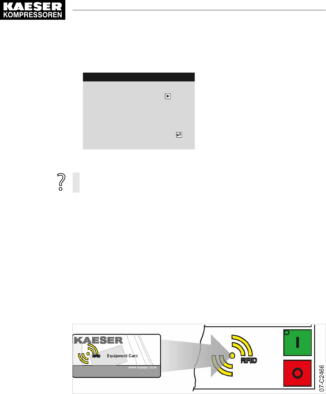
1. Hold the KAESER Equipment Card in front of the RFID reader.
Your user name and access level will be displayed.
88psi 08:15AM 176° F
Log-in successful Menu
Button to change password Prompt, whether the password is to be changed
__________________________________
Name: E00019895
Level: 2
2. Press «Enter» to confirm the access right.
The access right is confirmed.
The KAESER Equipment Card is damaged or lost?
➤ Manually enter the user name and password, see chapter 8.2.6.
8.2.5 Generating a password
In the event that your KAESER Equipment Card is damaged or lost, you must manually log on to
SIGMA CONTROL 2. A password is also required to use KAESER CONNECT to log on at
SIGMA CONTROL 2 (see chapter 8.3).
Prerequisite for this is that you know your
■ Name
■ Password
You have noted your user name and stored it at a suitable location (see chapter 8.2.3). You now
generate a password at the SIGMA CONTROL 2. Note this generated password as well, and store
it in a suitable location. If your KAESER Equipment Card is damaged or lost, the card won't be nec‐
essary to manually log on to SIGMA CONTROL 2 when you have these two pieces of information.
Precondition Any menu is displayed
Fig. 13 User log-in with KAESER Equipment Card
8 Initial Start-up
8.2 Configuring the controller
No.: 9_9450 07 USE
User Manual Controller
SIGMA CONTROL 2 SCREW FLUID ≥4.0.X 53

1. Hold the KAESER Equipment Card in front of the controller’s RFID reader.
Users are always logged on with password access level 2.
88psi 08:15AM 176° F
Log-in successful Menu
Button to change password Prompt, whether the password is to be changed
__________________________________
Name: E00019895
Level: 2
2. Press the «Right» key within five seconds.
The new
Password
is displayed.
88psi 08:15AM 176° F
Password changed Menu
__________________________________
Please take note of your new
password:
xFNDQRCnDn New password
3. Note the new password.
4. Store the password at a suitable location, if it should become necessary to manually log-on
without KAESER Equipment Card.
5. Press «Enter».
The setting is applied.
8.2.6 Manual user log-in
In the event that your KAESER Equipment Card is damaged or lost, you can manually log on to
SIGMA CONTROL 2.
Precondition The user name (see chapter 8.2.3) and password (see chapter 8.2.5) are known.
The operating mode is displayed.
1. Open the 7
User
menu.
2. Use «Up» or «Down» to select the
Name
line.
3. Press «Enter».
The setting mode is active.
A column with alphanumeric characters is displayed.
The selected character flashes.
8 Initial Start-up
8.2 Configuring the controller
54 User Manual Controller
SIGMA CONTROL 2 SCREW FLUID ≥4.0.X No.: 9_9450 07 USE

Fig. 14 Manual user log-in
4. Select the required character with the «Up» or «Down» keys.
5. Press the «Right» key.
The cursor jumps to the next position of the user name.
6. Enter the remaining characters of the user name in the same manner.
7. Press «Enter».
The user name is entered.
8. Use «Up» or «Down» to select the
Password
line.
9. Press «Enter».
Enter the remaining letters and digits of the password in the same manner.
The password is case sensitive!
10. Press «Enter».
The password is entered.
11. Use «Up» or «Down» to select the
[Login]
line.
12. Press «Enter».
Current access level: 2
is displayed.
Result You are now logged on to SIGMA CONTROL 2 with password access level 2, having manually in‐
put your user name and the password.
8.2.7 Checking and setting time and date
Precondition Password access level 2 is activated.
Checking and setting time
➤ When operating the machine with a timer program, check the time settings at least once
a year.
➤ You can automatically synchronize date and time using a time server. Manual setting of
the time is no longer required in this case. See chapter 8.2.15.
1. Open the 5.1
<Configuration – General>
menu.
2. Use the «Up» or «Down» keys to select the
Date/time
line.
8 Initial Start-up
8.2 Configuring the controller
No.: 9_9450 07 USE
User Manual Controller
SIGMA CONTROL 2 SCREW FLUID ≥4.0.X 55

3. Press the «DOWN» key.
88psi 08:15AM 176° F
5.1 General Menu
▶1 System information
·········
Model: XXXXXX Set machine type (SC2 FLUID)
·········
Date/time
04/13/16 08:15:37AM Date and time
4. Press the «Right» key.
5. Press «Enter».
The display for hours
00:00:00
flashes.
6. Use «Up» or «Down» to set the hours.
7. Press the «Right» key.
The display for minutes
00:00:00
flashes.
8. Use «Up» or «Down» to set the minutes.
9. Press the «Right» key.
The display for seconds
00:00:00
flashes.
10. Use «Up» or «Down» to set the seconds.
11. Press «Enter» to accept all settings.
The setting is applied.
12. Press «Escape» repeatedly to return to the main menu.
Checking and setting the date
Precondition Password access level 2 is activated.
1. Open the 5.1
<Configuration – General>
menu.
2. Use the «Up» or «Down» keys to select the
Date/time
line.
3. Press the «DOWN» key.
88psi 08:15AM 176° F
5.1 General Menu
▶1 System information
·········
Model: XXXXXX Set machine type (SC2 FLUID)
·········
Date/time
04/13/16 08:15:37AM Date and time
4. Press «Enter».
The display for days
00.00.00
flashes.
5. Use «Up» or «Down» to set the day.
6. Press the «Right» key.
The display for months
00.00.00
flashes.
8 Initial Start-up
8.2 Configuring the controller
56 User Manual Controller
SIGMA CONTROL 2 SCREW FLUID ≥4.0.X No.: 9_9450 07 USE

7. Use «Up» or «Down» to set the month.
8. Press the «Right» key.
The display for years
00.00.00
flashes.
9. Use the «Up» or «Down» keys to set the years.
10. Press «Enter».
The setting is applied.
11. Press «Escape» repeatedly to return to the main menu.
8.2.8 Set the time zone
Set the time zone for the SIGMA CONTROL 2 to ensure the timely automatic conversion from win‐
ter time (standard time) to daylight savings time, for example.
Precondition Password access level 2 is activated.
1. Open the 5.1
<Configuration – General>
menu.
2. Use the «Up» or «Down» keys to select the
Date/time
line.
3. Press «Down» twice.
88psi 08:15AM 176° F
5.1 General Menu
Model: XXXXXX Set machine type (SC2 FLUID)
·········
Date/time
04/13/16 08:15:37AM
US/Central Time zone
·········
4. Press «Enter».
The time zone display flashes.
5. Use «Up» or «Down» to set the time zone.
6. Press «Enter».
The setting is applied.
7. Press «Escape» repeatedly to leave this menu.
8.2.9 Setting display formats
When setting the language, the system automatically sets the units and the time and date formats.
You can manually change these settings.
Setting the date format
Select your preferred format:
Format Example
DD.MM.YY 30.07.16
YY-MM-DD 16–07–30
MM/DD/YY 07/30/16
Tab. 45 Date formats
8 Initial Start-up
8.2 Configuring the controller
No.: 9_9450 07 USE
User Manual Controller
SIGMA CONTROL 2 SCREW FLUID ≥4.0.X 57

Precondition Password access level 2 is activated.
1. Open the 5.1
<Configuration – General>
menu.
2. Use the «Up» or «Down» keys to select the
Date format
line.
88psi 08:15AM 176° F
5.1 General Menu
US/Central
·········
▶2 Time server
·········
Date format MM/DD/YY Date format
Time format hh:mm:ssAM/PM
3. Press «Enter».
The
MM/DD/YY
display flashes.
4. Use the «Up» or «Down» keys to set the date format.
5. Press «Enter».
The setting is applied.
6. Press «Escape» repeatedly to leave this menu.
Setting the time format
Select your preferred format for the time display:
Format Example
hh:mm:ss 13:33:45
hh:mm 13:33
hh:mm:ssAM/PM 01:33:45PM
hh:mmAM/PM 01:33PM
Tab. 46 Time formats
Precondition Password access level 2 is activated.
1. Open the 5.1
<Configuration – General>
menu.
2. Use the «Up» or «Down» keys to select the
Time format
line.
88psi 08:15AM 176° F
5.1 General Menu
US/Central
·········
▶2 Time server
·········
Date format MM/DD/YY
Time format hh:mm:ssAM/PM Time format
3. Press «Enter».
The
hh:mm:ssAM/PM
indication flashes.
8 Initial Start-up
8.2 Configuring the controller
58 User Manual Controller
SIGMA CONTROL 2 SCREW FLUID ≥4.0.X No.: 9_9450 07 USE

4. Use the «Up» or «Down» keys to set the time format.
5. Press «Enter».
The setting is applied.
6. Press «Escape» repeatedly to leave this menu.
Setting the pressure display units
Select your preferred display of the pressure unit:
Format Example
bar 5.5bar
hPa 5523hPa
MPa 0.55MPa
psi 80psi
at 5.6at
Tab. 47 Units of pressure
Precondition Password access level 2 is activated.
1. Open the 5.1
<Configuration – General>
menu.
2. Use the «Up» or «Down» keys to select the
Pressure unit
line.
88psi 08:15AM 176° F
5.1 General Menu
Time
format hh:mm:ssAM/PM
·········
Pressure unit psi Unit of pressure
Temperature unit °F Unit of temperature
·········
Display lighting
3. Press «Enter».
The display for the set unit flashes.
4. Use the «Up» or «Down» keys to set the unit.
5. Press «Enter».
The setting is applied.
6. Press «Escape» repeatedly to leave this menu.
Setting the temperature display units
Select your preferred display of the temperature unit:
Format Example
°C 46°C
K 319K
°F 114°F
Tab. 48 Units of temperature
8 Initial Start-up
8.2 Configuring the controller
No.: 9_9450 07 USE
User Manual Controller
SIGMA CONTROL 2 SCREW FLUID ≥4.0.X 59

Precondition Password access level 2 is activated.
1. Open the 5.1
<Configuration – General >
menu.
2. Use the «Up» or «Down» keys to select the
Temperature unit
line.
88psi 08:15AM 176° F
5.1 General Menu
Time
format hh:mm:ssAM/PM
·········
Pressure unit psi Unit of pressure
Temperature unit °F Unit of temperature
·········
Display lighting
3. Press «Enter».
The display for the set unit flashes.
4. Use the «Up» or «Down» keys to set the unit.
5. Press «Enter».
The setting is applied.
6. Press «Escape» repeatedly to leave this menu.
8.2.10 Setting the display illumination
Select your personal mode for the display illumination:
Mode 1 2 3
Indication
automatic on off
Function The illumination extin‐
guishes after the
time-
out
has elapsed.
Permanent setting
Illumination "on"
Permanent setting
Illumination "off"
Tab. 49 Display illumination
Precondition Access level 2 is activated.
1. Open the 5.1
<Configuration – General >
menu.
2. Use the «Up» or «Down» keys to select the
Display lighting
line.
3. Press the «DOWN» key.
The
Mode
line is displayed.
88psi 08:15AM 176° F
5.1 General Menu
·········
Pressure unit psi
Temperature unit °F
·········
Display lighting
Mode: auto. ¦ Timeout: 1min Active line
8 Initial Start-up
8.2 Configuring the controller
60 User Manual Controller
SIGMA CONTROL 2 SCREW FLUID ≥4.0.X No.: 9_9450 07 USE

4. Press «Enter».
The display for the set mode flashes.
5. Use the «Up» or «Down» keys to set the
auto.
mode.
6. Press «Enter».
The setting is applied.
7. Press the «Right» key.
8. Set the value for the
Timeout
in the same manner, e.g. 1 min.
9. Press «Enter».
10. Press «Escape» repeatedly to leave this menu.
Result The display illumination is set for automatic operation with deactivation following one minute with‐
out user intervention.
8.2.11 Setting the contrast and the brightness
The display settings for contrast and brightness are set to the highest possible values by default.
Change the settings if adverse lighting conditions make it difficult to read the displayed information.
Precondition The operating mode is displayed.
1. Press and hold the «Information» key.
2. Use «Up» or «Down» to adjust the contrast.
3. Use «Left» or «Right» to adjust the brightness.
Result The settings for contrast and brightness have been adjusted.
8.2.12 Activating the remote control
The «Remote control» key on the operating panel of the SIGMA CONTROL 2 can be activated or
deactivated. Various menus offer check boxes for this setting.
Precondition Password access level 2 is activated.
The operating mode is displayed.
1. Open the 8
Communication
menu.
2. Use «Up» or «Down» to select the
Key remote
line.
3. Press «Enter».
The check box
Key remote
flashes.
88psi 08:15AM 176° F
8 Communication Menu
▶1 Ethernet/SIGMA NETWORK
▶2 Com-Module
Key remote ☐ Active line with deactivated check box
8 Initial Start-up
8.2 Configuring the controller
No.: 9_9450 07 USE
User Manual Controller
SIGMA CONTROL 2 SCREW FLUID ≥4.0.X 61

4. Press the «Up» key.
The check box
Key remote
is activated.
88psi 08:15AM 176° F
8 Communication Menu
▶1 Ethernet/SIGMA NETWORK
▶2 Com-Module
Key remote ☑ Active line with activated check box
5. Press «Enter».
The «Remote control» key is activated.
6. Press «Escape» repeatedly to leave this menu.
Proceed in the same manner to deactivate the «Remote control» key.
7. Press the «Remote control» key on the operating panel of SIGMA CONTROL 2.
Result SIGMA CONTROL 2 Remote control is activated.
8.2.13 IP configuration
For the SIGMA CONTROL 2 to be connected to the network, you must set the IP configuration (for
KAESER CONNECT for example).
If you use SIGMA CONTROL 2 as the master control of two machines, you set other network
parameters in the
IP configuration
menu (see chapter 8.10.4).
The network parameters for the IP configuration must be specified manually. You cannot use
DHCP for an automatic IP configuration.
Precondition Password access level 2 is activated.
The network parameters are known. Request the required information from your IT department.
1. SIGMA CONTROL 2 Connect to the network using an Ethernet cable.
2. Select the 8.1.1
<Communication – Ethernet/SIGMA NETWORK – IP configuration>
menu.
3. Use «Up» or «Down» to select the
IP address
line.
88psi 08:15AM 176° F
8.1.1 IP configuration Menu
IP address 169.254.100.101 Active line, factory setting
Subnet mask 255.255.000.000
Gateway 169.254.100.97
DNS Server 1 169,254,100.97
DNS Server 2 169,254,100.97
Restart network ☐
4. Press «Enter» to switch into setting mode.
The first group of numbers of the
IP address
flashes
169.254.100.101
.
8 Initial Start-up
8.2 Configuring the controller
62 User Manual Controller
SIGMA CONTROL 2 SCREW FLUID ≥4.0.X No.: 9_9450 07 USE

5. Use «Up» or «Down» to set the first group of numbers of the
IP address
.
6. Press the «Right» key.
The SECOND group of numbers of the
IP address
flashes
192.168.100.101
.
7. Use «Up» or «Down» to set the second, third and fourth group of numbers of the
IP address
.
The
IP address
is correctly set.
8. Press «Enter» to accept the setting.
The setting is applied.
9. Press «Down».
The
Subnet mask
line is displayed.
10. Set the remaining network parameters as described above:
Parameters Setting value Meaning
IP address IP address of the interface X1 Ethernet
Subnet mask Subnet mask of the network
Gateway Gateway address of the network
DNS Server 1 DNS server 1 address
DNS Server 2 DNS server 2 address
Restart network – Activate the changed network parameters
Tab. 50 Network parameters
11. Use the «Up» or «Down» keys to select the
Restart network
line.
88psi 08:15AM 176° F
8.1.1 IP configuration Menu
IP address 192.168.001.010 Example address
Subnet mask 255.255.255.000 Example address
Gateway 192.168.001.001 Example address
DNS Server 1 008.008.008.008 Example address
DNS Server 2 008.008.004.004 Example address
Restart network ☐ Active line
12. Press «Enter».
The check box
Restart network
will flash.
13. Press «Up» key.
The check box is activated.
14. Press «Enter».
Result The network is restarted.
The set network parameters are active.
8.2.14 Setting the e-mail function
SIGMA CONTROL 2 uses e-mail to send information (messages) to an e-mail address.
For this purpose, an Ethernet connection with an SMTP server is required.
8 Initial Start-up
8.2 Configuring the controller
No.: 9_9450 07 USE
User Manual Controller
SIGMA CONTROL 2 SCREW FLUID ≥4.0.X 63

Setting e-mail parameters
Precondition Password access level 2 is activated.
IP configuration is set; see chapter 8.2.13
An SMTP server is active in the network.
The e-mail parameters are known. Request the required information from your IT department.
1. Open the 8.1.3
<Communication – Ethernet/SIGMA NETWORK – E-mail>
menu.
2. Use the «Up» or «Down» keys to select the
active:
line.
88psi 08:15AM 176° F
8.1.3 E-mail Menu
active: ☐ Activating/deactivating the e-mail function
Compressor number: 1
Language: English US Setting the language
Repeat cut-off time: 5min
__________________________________
Sender address:
3. Press «Enter».
The check box
active:
will flash.
4. Press «Up» key.
The check box is deactivated.
5. Press «Enter».
The e-mail function is deactivated.
6. Set the e-mail parameters as described above:
Parameters Setting
value
Meaning
Compressor
number:
This field displays the machine number that appears as the sender of
e-mails. The recipient is thus able to recognize the different machines
sending mails.
Language: Use this field to define the language for the message texts. This setting
in independent from the language setting in SIGMA CONTROL 2 (see
chapter 8.2.2).
Repeat cut-off
time:
In this field, enter the time in minutes (repeat block time) that the sys‐
tem must wait in order not send multiple recurring messages in short
time intervals.
Sender address: Enter the e-mail address of the sender in this field.
Sender name: Enter the name of the sender in this field.
Contact
telephone:
In this field, enter a telephone number under which the system operator
can be reached. This telephone number is sent with each e-mail.
Receiver
address:
The e-mail address of the recipient.
SMTP Server: IP address of the SMTP server receiving and forwarding the e-mails.
User name: Log-in user name for logging on to the SMTP server.
Password Log-in password for logging on to the SMTP server.
8 Initial Start-up
8.2 Configuring the controller
64 User Manual Controller
SIGMA CONTROL 2 SCREW FLUID ≥4.0.X No.: 9_9450 07 USE

Parameters Setting
value
Meaning
Port Port address of the SMTP server.
Timeout In this field, enter the seconds for SIGMA CONTROL 2 to wait for a re‐
ply by the SMTP server before e-mail sending is cancelled.
Resend after: In this field enter, the time in seconds for the system to wait after a
failed e-mail sending operation before it again attempts to send the
mail.
Tab. 51 E-mail parameters
7. Activating the e-mail function: Activate the
active:
check box as described above.
8. Press «Esc» repeatedly to leave this menu.
Result The e-mail parameters are set and the e-mail function is activated.
8.2.15 Configuring the time server
If SIGMA CONTROL 2 is connected to the network, you can set the access to an SNTP server
available in the Internet or a local Intranet. SIGMA CONTROL 2 then automatically imports the
date and time settings and ensures continuous synchronization of the internal clock with the exter‐
nal time server.
Precondition Password access level 2 is activated.
IP configuration is set; see chapter 8.2.13.
The time server's IP address is known. Request the required information from your IT department.
1. Open the 5.1.2
<Configuration – General – Time server>
menu.
2. Use the «Up» or «Down» keys to select the
IP address
line.
88psi 08:15AM 176° F
5.1.2 Time server Menu
active: ☐ Activating/deactivating the time server function
IP address 192.053.103.103 Example address, time server
3. Press «Enter».
The first group of numbers of the
IP address
flashes
192.053.103.103
.
4. Use «Up» or «Down» to set the first group of numbers of the
IP address
.
5. Press the «Right» key.
The second group of numbers of the
IP address
flashes
192.053.103.103
.
6. Use «Up» or «Down» to set the second, third and fourth group of numbers of the
IP address
.
The
IP address
is correctly set.
7. Press «Enter» to accept the setting.
The setting is applied.
8. Use «Up» or «Down» to select the
active:
line.
8 Initial Start-up
8.2 Configuring the controller
No.: 9_9450 07 USE
User Manual Controller
SIGMA CONTROL 2 SCREW FLUID ≥4.0.X 65

9. Press «Enter».
The check box
active:
will flash.
10. Press «Up» key.
The check box is activated.
88psi 08:15AM 176° F
5.1.2 Time server Menu
active: ☑ The time server function is activated
IP address 192.053.103.103 Example address, time server
11. Press «Enter».
12. Press «Escape» repeatedly to return to the main menu.
Result Access to the selected time server is active.
The internal clock of SIGMA CONTROL 2 is permanently synchronized.
8.3 Using KAESER CONNECT
Using an Internet-capable device with web browser, you can use KAESER CONNECT to remotely
display these SIGMA CONTROL 2 menus:
■ System status
■ Graphs
■ Messages
■ I/O display
■ User management
■ Settings
■ Backup
■ Data recording
Thus, KAESER CONNECT provides an excellent option for an easy and quick check of the econo‐
my and energy efficiency of your machines.
The following functions are not available with KAESER CONNECT:
■ Remotely starting the machine
■ Remotely setting parameters
For KAESER CONNECT to be able to use the Internet-capable device, it must be registered
in the same network as SIGMA CONTROL 2.
To be able to use KAESER CONNECT, the browser installed on the Internet-capable device
must be able to display HTML5 content. For security reasons, we strongly recommend to use
only up-to-date browser versions.
8 Initial Start-up
8.3 Using KAESER CONNECT
66 User Manual Controller
SIGMA CONTROL 2 SCREW FLUID ≥4.0.X No.: 9_9450 07 USE
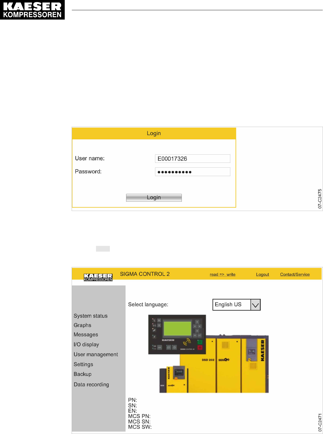
8.3.1 Open KAESER CONNECT
Precondition The user name (see chapter 8.2.3) and password (see chapter 8.2.5) are known.
The IP address of your controller is known, see chapters 8.2.13 and 8.10.4.
1. Use an Ethernet cable to connect SIGMA CONTROL 2 to the Internet-capable device or net‐
work.
2. In the web browser, enter the controller's IP address.
The Login window is displayed.
Fig. 15 Login window
3. Enter your user name in the
User name:
field.
4. Enter your password in the
Password:
field.
5. Click Login.
KAESER CONNECT for SIGMA CONTROL 2 is displayed.
Fig. 16 KAESER CONNECT for SIGMA CONTROL 2
8 Initial Start-up
8.3 Using KAESER CONNECT
No.: 9_9450 07 USE
User Manual Controller
SIGMA CONTROL 2 SCREW FLUID ≥4.0.X 67
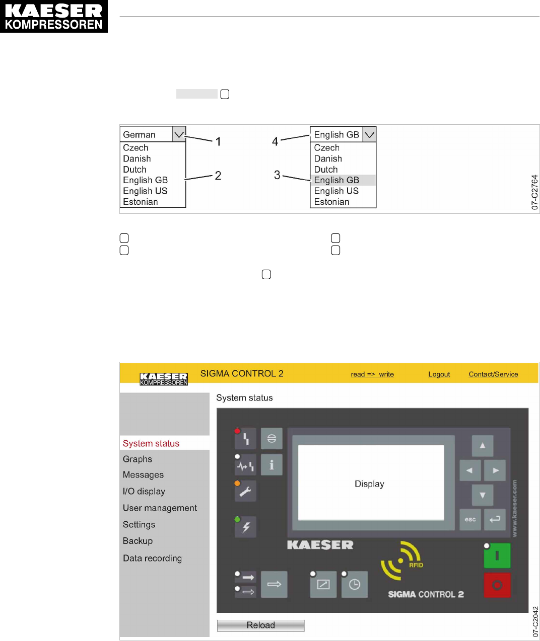
6. Click the arrow key 1 to open Select language:.
The
Select language:
window is displayed.
Fig. 17 Select language: window
1«Arrow key» Select language:
2Select language: window
3Select a language
4Selected language
7. Select the required language 3.
Result KAESER CONNECT is displayed in the selected language.
8.3.2 System status menu
Precondition KAESER CONNECT for SIGMA CONTROL 2 is displayed.
Fig. 18
System status
menu
1. Click the
System status
menu element.
The
System status
menu is displayed
8 Initial Start-up
8.3 Using KAESER CONNECT
68 User Manual Controller
SIGMA CONTROL 2 SCREW FLUID ≥4.0.X No.: 9_9450 07 USE
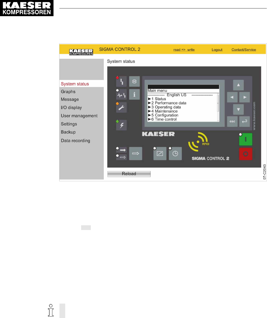
Fig. 19 Main menu
2. Click in the SIGMA CONTROL 2 display.
The Main menu is displayed.
3. Click the numbered lines.
The system displays the corresponding sub-menus.
4. Press ESC repeatedly to leave this menu.
8.3.3 Graphs menu
When starting the
Graphs
menu, the recorded data from the last 60 minutes are loaded. The last
20 minutes are displayed in a graph. The system updates the graph every ten seconds whilst the
current time is displayed.
If an SD card is provided in the X5 SD card slot, you can retrieve and display the automatically-
recorded machine data for any time in the past.
Moving the mouse pointer across the graph calls up a ruler. The time selected with the ruler and
the associated values are displayed in the legend above the graph. When the ruler is hidden, the
time and associated values are displayed at the right edge of the graph.
The graph content depends on the machine type.
The
Speed
display is implemented only for machines with frequency converter.
Precondition KAESER CONNECT for SIGMA CONTROL 2 is displayed.
1. Click the
Graphs
menu element.
8 Initial Start-up
8.3 Using KAESER CONNECT
No.: 9_9450 07 USE
User Manual Controller
SIGMA CONTROL 2 SCREW FLUID ≥4.0.X 69

Fig. 20
Graphs
(illustration similar)
2. Check the displayed data.
8.3.3.1 Zoom function
Use the Zoom function to enlarge significant curve developments:
Highlight a specific area within the graph by drawing a rectangle with the mouse pointer pressed.
The selected area will be enlarged as soon as the mouse pointer is released.
Fig. 21 Arrow keys
Item Description Function
1 «Start» Display the oldest data in the cache memory or load the data from the previ‐
ous 20 minutes from the SD card
2 «Scroll left» Shift the display area by 1/3 to the left
3 «Zoom-out» Time range is enlarged
4 «Scroll right» Shift the display area by 1/3 to the right
5 «End» Display of newest data
6 «Refresh» Load and display the entered machine data from start time to end time
Tab. 52 Arrow key functions
8 Initial Start-up
8.3 Using KAESER CONNECT
70 User Manual Controller
SIGMA CONTROL 2 SCREW FLUID ≥4.0.X No.: 9_9450 07 USE

1. Click the «Start» 1 arrow key.
The oldest data in the cache memory or the data of the last 20 minutes are loaded form the SD
card and displayed
2. Click the «Scroll right» 4 arrow key.
The display area is shifted to the right by 1/3.
3. With the mouse button pressed, draw a rectangle around the selected area.
4. Release the mouse button.
The selected area is enlarged (zoom-in function).
5. Click the «Zoom-out» 3 arrow key.
The time range is enlarged (zoom-out function).
8.3.3.2 Displaying past machine data
You can display the automatically-recorded machine data for any time in the past.
Precondition An SD card with sufficient free memory is inserted in the X5 SD card slot
The SD card was inserted for the entire operating time of the machine.
The SIGMA CONTROL 2 data recorder function is activated.
1. Enter the date and time for the start time in the required time period in
Start:
.
2. Enter the date and time for the end time in the required time period in
End:
.
3. Click 6.
The machine data for the specified time interval are loaded and displayed.
8.3.4 Messages menu
The following messages are shown:
■ Current messages
■ Compressor messages
■ System messages
■ Diagnostic messages
Precondition KAESER CONNECT for SIGMA CONTROL 2 is displayed.
8 Initial Start-up
8.3 Using KAESER CONNECT
No.: 9_9450 07 USE
User Manual Controller
SIGMA CONTROL 2 SCREW FLUID ≥4.0.X 71

Fig. 22
Messages
1. Open the
Messages
menu.
The
Messages
menu is displayed.
2. Click the required message type.
3. Check messages.
8.3.5 I/O display menu
The measured values of the analog inputs and the states of the digital inputs and outputs are dis‐
played in the
I/O display
menu. Depending on the machine options, you may select from further
IOM module tabs.
Precondition KAESER CONNECT for SIGMA CONTROL 2 is displayed.
8 Initial Start-up
8.3 Using KAESER CONNECT
72 User Manual Controller
SIGMA CONTROL 2 SCREW FLUID ≥4.0.X No.: 9_9450 07 USE

Fig. 23
I/O display
(illustration similar)
➤ Click the
I/O display
menu element.
The current measured data and states of the input/output modules are displayed.
8.3.6 User management menu
Use the
User management
menu to create additional user accounts for other employees.
In order to be able to create user accounts, you must activate the write mode. The system will
prompt you to enter and confirm your user name and your password. Subsequently, the write
mode is activated (see Chapter 8.2.5).
The write mode is granted only to one person at a time.
If a second user attempts to log on in write mode, he will be refused by the system.
The system will return an error message.
String length for personally created user names and passwords:
■ User name: 6 to 16 characters, the second character must not be a number
■ Password: 6 to 16 characters
Precondition The generated password is available.
KAESER CONNECT for SIGMA CONTROL 2 is displayed.
8 Initial Start-up
8.3 Using KAESER CONNECT
No.: 9_9450 07 USE
User Manual Controller
SIGMA CONTROL 2 SCREW FLUID ≥4.0.X 73

Fig. 24
User management
menu
1. Select the
User management
menu element.
2. Click
read => write
to activate the read/write mode.
The
Log on for write access:
window is displayed.
Fig. 25
Log on for write access:
window
3. Enter your user name in the
User name:
field.
4. Enter your password in the
Password:
field.
5. Click OK.
The
User management
menu is displayed.
8 Initial Start-up
8.3 Using KAESER CONNECT
74 User Manual Controller
SIGMA CONTROL 2 SCREW FLUID ≥4.0.X No.: 9_9450 07 USE

Fig. 26
User management
menu
6. Enter a new user name in the
User name:
field.
7. Enter a new password in the
Password:
field.
8. Re-enter the same new password in the
Repeat password:
field.
9. Set Level 2 in the
Access level:
field.
10. Set the
State:
option in the Enabled field.
11. Click Add.
The new user name has been added to the user list.
Result A new user account has been created and activated.
Editing a user account
You can edit existing user accounts:
■ Changing the password
■ Changing the access level
■ Changing the status
Example: Change the password for an existing user account.
Precondition The
User management
menu is displayed.
Write mode is activated.
1. Click the required user account in the list.
2. Enter a new password in the
Password:
field.
3. Re-enter the same new password in the
Repeat password:
field.
4. Click Update user.
8 Initial Start-up
8.3 Using KAESER CONNECT
No.: 9_9450 07 USE
User Manual Controller
SIGMA CONTROL 2 SCREW FLUID ≥4.0.X 75

Result The password for the existing user account is changed.
8.3.7 Settings
Settings via KAESER CONNECT apply only to your PC and your Browser.
The following settings are available.
■ Units
■ Date format
■ Time format
Fig. 27
Settings
Converting units to US values:
Precondition KAESER CONNECT for SIGMA CONTROL 2 is displayed.
1. Select the
Settings
menu.
2. Click the arrow key for the unit of pressure.
A selection list of units of pressure is displayed.
3. Select the desired unit.
4. Click the arrow key for the unit of temperature.
A selection list of units of temperature is displayed.
5. Select the desired unit.
6. Set additional units and date and time formats.
8 Initial Start-up
8.3 Using KAESER CONNECT
76 User Manual Controller
SIGMA CONTROL 2 SCREW FLUID ≥4.0.X No.: 9_9450 07 USE

8.3.8 Backup menu
The
Backup
menu allows you to download data from SIGMA CONTROL 2 to the Internet-capable
device.
The following backup types are available:
■ Backup all
■ Log files
■ Settings
■ User information
Precondition KAESER CONNECT for SIGMA CONTROL 2 is displayed.
1. Click the
Backup
menu element.
Fig. 28
Backup
menu
2. Set the required backup type in the
Select source:
option.
3. Click Backup.
Result The data are downloaded to the Internet-capable device.
8.3.9 Closing KAESER CONNECT
In order to close KAESER CONNECTfor SIGMA CONTROL 2, click Logout in the header.
➤ Click Logout.
The system displays a message confirming the successful logout.
8 Initial Start-up
8.3 Using KAESER CONNECT
No.: 9_9450 07 USE
User Manual Controller
SIGMA CONTROL 2 SCREW FLUID ≥4.0.X 77

8.4 Adjusting the pressure parameters of the machine
This section contains instructions for how to display and adjust the pressure parameters of the ma‐
chine.
The section is divided into the following sections:
■ 8.4.1: Displaying pressure parameters
■ 8.4.2: Configuring the pressure parameters
"Display" means that the parameter will only be shown.
"Setting" means that the parameter can also be changed.
Parameters Explanation
pRV Display:
Activating pressure of the safety relief valve on the oil separator tank.
pE Pressure increase.
Setting:
■ pE SP: Switching point for pressure increase; upper safety limit for machine
maximum pressure; in an external LOAD control, this value is used to switch
the machine from LOAD to IDLE in the event of a fault.
■ pE SD: Switching differential of pressure increase.
ΔpFC Limiting value for machines with frequency-controlled drive (SFC).
Setting:
■ dp FC: Limit of the lowest delivery quantity. When the value [switching point
system setpoint pressure +dp FC] is exceeded, the compressor switches from
LOAD to IDLE.
Nominal
pressure
Display:
The compressor is designed for this pressure (maximum system pressure set‐
point).
Setpoint
pressure
Setpoint pressure can be regulated to two values: pA and pB.
Setting:
■ Switching point pA or control pressure pA in machines with frequency convert‐
er (SFC).
■ Switching point pB or control pressure pB in machines with frequency convert‐
er (SFC).
System
pressure low
A warning message is displayed when the limit value for the system pressure is
reached.
Setting:
■ SD: Switching differential for system pressure low.
↓: Switching point for system pressure low.
■ Option: Configure the output signal.
Warning message displayed or an additional output signal is sent, e.g., to a
control center.
8 Initial Start-up
8.4 Adjusting the pressure parameters of the machine
78 User Manual Controller
SIGMA CONTROL 2 SCREW FLUID ≥4.0.X No.: 9_9450 07 USE

Parameters Explanation
Cut-in
pressure min
Display:
For design reasons, pressure can only be built up above this value.
Tab. 53 Compressor pressure parameters
➤ Parameters correspond to the following specifications.
8.4.1 Displaying pressure parameters
Precondition Password access level 2 is activated.
Opening the menu for pressure parameters
1. Open the 5.2.2
<Configuration – Pressure control – Pressure settings>
menu.
2. Press «Enter».
The
Pressure settings
menu is displayed.
88psi 08:15AM 176° F
5.2.2 Pressure settings Menu
Setpoint pressure
pA SP: 116psi ¦ SD: −7.3psi Active line
pB SP: 109psi ¦ SD: −5.8 psi
·········
System pressure low ☐
↓ < 72.5psi ¦ SD: 7.2psi
Displaying further parameters
1. Use the «Up» or «Down» keys to select the
Cut-in pressure min
line.
88psi 08:15AM 176° F
5.2.2 Pressure settings Menu
System pressure low ☐
↓ < 72.5psi ¦ SD: 7.2psi
ta: 600s
DOR1.03 ☐ ¦ Logic: +
__________________________________
Cut-in pressure min : 72.5psi Active line
2. Display further parameters with the «Up» and «Down» keys.
8.4.2 Configuring the pressure parameters
8.4.2.1 Adjusting the system setpoint pressure: pA and pB
The pressure parameters can only be set within certain limits:
Rated machine pressure ≥ SP: pA pB / ≥ Min. cut-in pressure* + switching differential
Tab. 54 Setting limits for the system setpoint pressure (* Cut-in pressure min)
8 Initial Start-up
8.4 Adjusting the pressure parameters of the machine
No.: 9_9450 07 USE
User Manual Controller
SIGMA CONTROL 2 SCREW FLUID ≥4.0.X 79

The machine switches to LOAD under the following condition:
System pressure ≤ SP: pA /pB - switching differential
Tab. 55 Pressure condition for LOAD
The machine switches to IDLE under the following conditions:
System pressure = System setpoint pressure
Tab. 56 Pressure conditions for IDLE
Precondition Password access level 2 is activated.
1. Select the 5.2.2
<Configuration – Pressure control – Pressure settings>
menu.
2. Use «Up» or «Down» to select the
pASP
line.
88psi 08:15AM 176° F
5.2.2 Pressure settings Menu
·········
Setpoint pressure
pA SP: 116psi ¦ SD: −7.3psi Active line with current value for system setpoint
pressure pA
pB SP: 109psi ¦ SD: −5.8 psi
·········
System pressure low ☐
3. Press «Enter».
The setting mode is active.
4. Use «Up» or «Down» to adjust the
pA SP
value.
5. Press «Enter» to accept the setting.
The setting is applied.
6. Adjust the
SD
switching differential in the same way.
7. Adjust the
pB SP
and the
SD
switching differential in the same manner, if necessary.
8. Press «Escape» repeatedly to return to the main menu.
Result The settings for the system setpoint pressure
pA
and
pB
are adjusted.
8.4.2.2 Adjusting the value for "System pressure low"
If the system pressure falls to the
System pressure low
value, SIGMA CONTROL 2 will display a
warning message for the system pressure being too low.
Be generous when setting the time value for the display of the warning message.
If the time interval is set too short, the system will display a warning message despite the machine
delivering compressed air and approaching the preset value for the system setpoint pressure.
The switching differential influences the pressure level at which the message can be acknowledged
or the optionally activated output can switch again:
Message Output
72.5 psi message appears Active
80.0 psi message disappears Inactive
Tab. 57 Example: activated output
8 Initial Start-up
8.4 Adjusting the pressure parameters of the machine
80 User Manual Controller
SIGMA CONTROL 2 SCREW FLUID ≥4.0.X No.: 9_9450 07 USE

Precondition Password access level 2 is activated.
1. Select the 5.2.2
<Configuration – Pressure control – Pressure settings>
menu.
2. Use «Up» or «Down» to select the
↓<
line.
88psi 08:15AM 176° F
5.2.2 Pressure settings Menu
·········
System pressure low ☐
↓ < 72.5psi ¦ SD: 7.2psi Current system pressure low point
ta: 600s
DOR1.03 ☐ ¦ Logic: +
__________________________________
3. Press «Enter» to switch into setting mode.
The setting mode is active.
4. Use «Up» or «Down» to adjust the value for
System pressure low
.
5. Press «Enter» to accept the setting.
The setting is applied.
6. Adjust the
SD
switching differential in the same way, if necessary.
7. Press «Escape» repeatedly to leave this menu.
8.4.2.3 Adjusting the SD switching differential of the pressure increase
The value for pressure rise
pE SP
serves as a safety limit value when the machine is externally
controlled. When the system setpoint pressure reaches the value
pE SP
(for example, when the
external control functions incorrectly) the machine switches to IDLE. The warning message
External load signal?
is displayed.
The parameter for
pE SP
pressure increase is preset and cannot be changed. You can, however,
adjust the
SD
switching differential.
Displaying and adjusting the pressure increase parameters:
Pressure increase Display parameters Setting parameters
Switching point
pE SP
x –
Switching differential
SD
x x
x = fitted, − = not fitted
Tab. 58 Displaying and adjusting parameters
Precondition Password access level 2 is activated.
1. Select the 5.2.2
<Configuration – Pressure control – Pressure settings>
menu.
8 Initial Start-up
8.4 Adjusting the pressure parameters of the machine
No.: 9_9450 07 USE
User Manual Controller
SIGMA CONTROL 2 SCREW FLUID ≥4.0.X 81

2. Use «Up» or «Down» to select the
pESP
line.
88psi 08:15AM 176° F
5.2.2 Pressure settings Menu
pRV: 232psi
__________________________________
Pressure rise
pE SP: 122psi ¦ SD: −8.7psi Active line
ΔpFC: 2.9psi
·········
3. Press «Enter» to switch into setting mode.
The setting mode is active.
4. Use «UP» or «DOWN» to adjust the required value for
SD
.
5. Press «Enter» to accept the setting.
The setting is applied.
6. Press «Escape» repeatedly to return to the main menu.
8.4.3 Activating/deactivating the «LOAD/IDLE» key
In order to prevent unauthorized users from switching the machine to IDLE, you can deactivate the
«LOAD/IDLE» key on the SIGMA CONTROL 2 operating panel.
Precondition Password access level 2 is activated.
1. Select the 5.2.3
<Configuration – Pressure control – Load control>
menu.
2. Use «Up» or «Down» to select the
Key idle
line.
3. Press «Enter» to switch into setting mode.
The check box
Key idle
will flash.
88psi 08:15AM 176° F
5.2.3 Load control Menu
Logic : +
loc.-load RC DI1.07 ☑
Logic : +
·········
Key remote: ☐
Key idle: ☑ Active line with activated check box
4. Press the «Up» key.
The deactivated check box is displayed.
8 Initial Start-up
8.4 Adjusting the pressure parameters of the machine
82 User Manual Controller
SIGMA CONTROL 2 SCREW FLUID ≥4.0.X No.: 9_9450 07 USE

5. Press «Enter» to save the setting.
The «IDLE» key is deactivated.
88psi 08:15AM 176° F
5.2.3 Load control Menu
Logic : +
loc.-load RC DI1.07 ☑
Logic : +
·········
Key remote: ☐
Key idle: ☐ Active line with deactivated check box
6. Press «Escape» repeatedly to return to the main menu.
Result Thus, it is ensured that unauthorized users can press the «IDLE» key without the machine switch‐
ing to IDLE.
8.5 Configuring machine start and stop
➤ In addition to manually starting the machine locally, you have the following alternatives:
Function State on delivery, setting See
Automatic start/stop in timer mode No clock (time) program set 8.5.1
Holidays Not set 8.5.2
Remote start, e.g. from a control center Deactivated 8.5.3
"Venting" function Activated 8.5.5
"Autostart" function Activated 8.5.6
Tab. 59 Settings for machine start and stop
8.5.1 Automatic start/stop in timer mode
Overview
■ Selecting the
Compressor clock
menu
■ Setting/adjusting the time program
■ Activating the «Clock» key
■ Activating timer control
8.5.1.1 Compressor clock
Precondition Password access level 2 is activated.
8 Initial Start-up
8.5 Configuring machine start and stop
No.: 9_9450 07 USE
User Manual Controller
SIGMA CONTROL 2 SCREW FLUID ≥4.0.X 83
1. Open the 6
Compressor clock
menu.
The
Compressor clock
menu is displayed.
88psi 08:15AM 176° F
6 Compressor clock Menu
Key clock : ☐ The Timer control key is activated
Reset : ☐ All current switching points are reset
·········
01 n.a. 00:00AM off Active line
02 n.a. 00:00AM off
03 n.a. 00:00AM off
User-defined clock program:
No.: Day Time Function
01
02
03
04
05
06
07
08
09
10
Tab. 60 User-defined clock program machine ON/OFF
8.5.1.2 Setting/adjusting the clock program (example)
When setting a clock program for the first time, note the switching times on the "User-defined
clock program" table.
In addition to individual weekdays, the controller has the following cycles:
■ Mon-Thu
■ Mon-Fri
■ Mon-Sat
■ Mon-Sun
■ Sat-Thu
You can also program an OFF time (plant vacation shutdown, for example) (see Sec‐
tion 8.5.2).
Example
■ Machine ON: On weekdays 06:30AM – 05:00PM, Fridays 06:30AM – 03:00PM
■ Machine OFF: Sat – Sun and during midday break 12:00PM – 01:00PM
8 Initial Start-up
8.5 Configuring machine start and stop
84 User Manual Controller
SIGMA CONTROL 2 SCREW FLUID ≥4.0.X No.: 9_9450 07 USE

The following switching points result:
No.: Day Time Function
01 Mon-Fri 06:30AM on
02 Mon-Fri 12:00PM off
03 Mon-Fri 01:00PM on
04 Mon-Thu 05:00PM off
05 Fri 03:00PM off
Tab. 61 Example of a machine ON/OFF clock program
Precondition Password access level 2 is activated.
1. Select the 6
Compressor clock
menu.
2. Use «Up» or «Down» to select the
01
line.
88psi 08:15AM 176° F
6 Compressor clock Menu
·········
01 n.a. 00:00AM off Active line with switching point 01
02 n.a. 00:00AM off Switching point 02
03 n.a. 00:00AM off Switching point 03
04 n.a. 00:00AM off Switching point 04
05 n.a. 00:00AM off Switching point 05
3. Press «Enter» to switch into setting mode.
The
n.a.
column flashes in the active line.
4. Use the «Up» or «Down» keys to specify the settings for the weekdays.
5. Press «Enter» to accept the setting.
The setting is applied.
6. Press the «Right» key.
7. Press «Enter» to switch into setting mode.
The column time, display for hours,
00:00
flashes in the active line.
8. Use «Up» or «Down» to specify the settings for the hours.
9. Press the «Right» key.
10. The column time, display for minutes, 00:
00
flashes in the active line.
11. Use «Up» or «Down» to specify the settings for the minutes.
8 Initial Start-up
8.5 Configuring machine start and stop
No.: 9_9450 07 USE
User Manual Controller
SIGMA CONTROL 2 SCREW FLUID ≥4.0.X 85

12. Press «Enter» to accept the setting.
The setting is applied.
88psi 08:15AM 176° F
6 Compressor clock Menu
·········
01 Mon-Fri 06:30AM on Switching point 01 is set
02 Mon-Fri 12:00PM off Switching point 02 is set
03 Mon-Fri 01:00PM on Switching point 03 is set
04 Mon-Thu 05:00PM off Switching point 04 is set
05 Fri 03:00PM off Switching point 05 is set
13. Press the «Right» key.
14. Press «Enter» to switch into setting mode.
The
on/off
indicator flashes.
15. Use «Up» or «Down» to specify the settings for the action Compressor On.
16. Press «Enter» to accept the setting.
The setting is applied.
The action Compressor ON is set for the first switching point.
17. Specify further switching points in the same manner.
Result Weekdays, time and the Compressor ON/Compressor OFF actions are set for all switching points
of the user-defined clock program.
8.5.1.3 Activating the «Timer control» key
1. Use «Up» or «Down» to select the
Key clock
line.
2. Press «Enter» to switch into setting mode.
The check box
Key clock
flashes in the active line.
88psi 08:15AM 176° F
6 Compressor clock Menu
Key clock : ☑ Active line with deactivated check box
Reset : ☐
·········
01 Mon-Fri 06:30AM on Switching point 01
02 Mon-Fri 12:00PM off Switching point 02
03 Mon-Fri 01:00PM on Switching point 03
3. Press the «Up» key to activate the check box.
The check box is activated.
4. Press «Enter» to accept the setting.
The setting is applied.
5. Press «Escape» repeatedly to return to the main menu.
Result The «Timer control» key is activated.
The activated key «Timer control» can be used for activating the timer control.
8 Initial Start-up
8.5 Configuring machine start and stop
86 User Manual Controller
SIGMA CONTROL 2 SCREW FLUID ≥4.0.X No.: 9_9450 07 USE

8.5.1.4 Activating timer control
Precondition The «Timer control» key is activated; see chapter 8.5.1.3.
➤ Press the «Timer control» key on the SIGMA CONTROL 2 operating panel to activate the time
control.
Result The
Timer control
LED on the operating panel of the SIGMA CONTROL 2 signalizes with
green
continuous light
that the machine is operated with activated timer control.
The timer control of SIGMA CONTROL 2 switches the machine according to the defined switching
points of the timer program.
8.5.2 Setting up the holiday period
In addition to the fixed cycles of a timing program or timer, you can also specify a longer lasting
standstill time. For example, you may specify a standstill period for vacation shutdown by defining
the following:
Precondition Password access level 2 is activated.
1. Select the 5.4.2
<Configuration – Compressor start – Compressor off>
menu.
2. Use «Up» or «Down» to select the
Start
line.
88psi 08:15AM 176° F
5.4.2 Compressor off Menu
·········
Holidays : ☐
Start : 01/01/16 Active line
00:00AM
End : 01/01/16
03:00AM
3. Press «Enter» to switch into setting mode.
The display for days
00.00.00
flashes.
4. Use «Up» or «Down» to set the day.
5. Press the «Right» key.
The display for months
00.00.00
flashes.
6. Use «Up» or «Down» to set the month.
7. Press the «Right» key.
The display for years
00.00.00
flashes.
8. Use the «Up» or «Down» keys to set the year.
9. Press «Enter» to accept the setting.
The setting is applied.
10. Press «Down».
11. Press «Enter» to switch into setting mode.
The display for hours
00:00:00
flashes.
12. Use «Up» or «Down» to set the hours.
13. Press the «Right» key.
The display for minutes
00:00:00
flashes.
8 Initial Start-up
8.5 Configuring machine start and stop
No.: 9_9450 07 USE
User Manual Controller
SIGMA CONTROL 2 SCREW FLUID ≥4.0.X 87

14. Use «Up» or «Down» to set the minutes.
15. Press «Enter» to accept the setting.
The date and time for the start of the company shutdown are set.
16. Adjust the date and time for the end of the company shutdown in the same manner.
88psi 08:15AM 176° F
5.4.2 Compressor off Menu
·········
Holidays : ☐
Start : 12/23/16 Date for start
05:00PM Time for start
End : 01/04/17 Date for end
06:30AM Time for end
17. Use «Up» or «Down» to select the
Holidays
line.
88psi 08:15AM 176° F
5.4.2 Compressor off Menu
·········
Holidays : ☐ Active line
Start : 12/23/16
05:00PM
End : 01/04/17
06:30AM
18. Press «Enter» to switch into setting mode.
The check box
Holidays
will flash.
19. Press the «UP» key to activate the check box.
The check box is activated.
88psi 08:15AM 176° F
5.4.2 Compressor off Menu
·········
Holidays : ☑ Active line with activated check box
Start : 12/23/16 Date for start
05:00PM Time for start
End : 01/04/17 Date for end
06:30AM Time for end
20. Press «Enter» to accept the setting.
Result In this example, a company shutdown (standstill time) for the time between 12/23/16 / 05:00PM
until 01/04/17 / 06:30AM has been set for the machine.
8.5.3 Starting the machine remotely (Remote ON/OFF)
If the machine is to be started and stopped remotely, the following settings have to be set:
8 Initial Start-up
8.5 Configuring machine start and stop
88 User Manual Controller
SIGMA CONTROL 2 SCREW FLUID ≥4.0.X No.: 9_9450 07 USE

Overview
■ Making the electrical connection (a spare input for the remote contact can be found in the elec‐
trical wiring diagram for the machine, DI 1.07 being preferred).
■ Switching machine start to remote mode.
■ Activating the «Remote control» key.
■ Activating the «Timer control» key and configuring the clock program (see chapter 8.5.1.2), if
necessary.
■ Assigning a different input for the remote contact
RC
, if required.
■ Pressing the «Remote control» key.
8.5.3.1 Switching machine start to Remote mode
Two methods are available to start the machine remotely from a control center:
■ Variant A: Starting the machine with the input signal from the remote control center.
■ Variant B: Starting the machine from the remote control center in addition to a configured
ON/OFF clock program.
The machine can be started from the remote control center even though the timer control is
activated and the ON/OFF program has selected OFF at this point in time.
Precondition The electrical connection has been made.
Password access level 2 is activated.
The operating mode is displayed.
1. Open the 5.4.1
<Configuration – Compressor start – Compressor on>
menu.
2. Use «Up» or «Down» to select the
Remote mode
line.
3. Press the «DOWN» key.
4. Press «Enter» to switch into setting mode.
The currently active operating mode flashes.
88psi 08:15AM 176° F
5.4.1 Compressor on Menu
Local mode:
Key
Remote mode:
Key Active line
__________________________________
RC DI1.07 ok ☑
5. Use «Up» or «Down» to set the
Key + remote contact
input.
8 Initial Start-up
8.5 Configuring machine start and stop
No.: 9_9450 07 USE
User Manual Controller
SIGMA CONTROL 2 SCREW FLUID ≥4.0.X 89
6. Press «Enter» to accept the setting.
The setting is applied.
88psi 08:15AM 176° F
5.4.1 Compressor on Menu
Local mode:
Key
Remote mode:
Key + remote contact Active line
__________________________________
RC DI1.07 ok ☑
Result The machine start is set to
Remote mode
Key + remote contact
.
8.5.3.2 Assigning another input
Inputs already assigned cannot be further assigned.
1. Use «Up» or «Down» to select the
RC
line.
88psi 08:15AM 176° F
5.4.1 Compressor on Menu
__________________________________
RC DI1.07 ok ☑ Remote contact DI 1.07 (default)
Logic : +
·········
Key remote : ☑
Key clock : ☐
2. Press «Enter» to switch into setting mode.
The display for the currently set input flashes.
3. Select another input with the «Up» or «Down» keys.
4. Press «Enter» to accept the setting.
The input has now been assigned.
5. Press the «Remote control» key to enable the machine to be started from the remote control
center.
If an input is rejected it means it is already assigned.
➤ Select a different input.
8.5.4 Activating the remote control
➤ Activating remote control, see chapter 8.2.12.
Result SIGMA CONTROL 2 remote control is activated.
8 Initial Start-up
8.5 Configuring machine start and stop
90 User Manual Controller
SIGMA CONTROL 2 SCREW FLUID ≥4.0.X No.: 9_9450 07 USE

8.5.5 Activating/deactivating the idle period "Venting period" function
Prior to the machine's transition from the operating modes LOAD to READY you can also activate
an IDLE period ("Venting period" function). The duration of the IDLING period can be timed and/or
regulated by internal pressure. The machine-dependent venting period between the LOAD and
READY operating modes ensures load changes at minimum material stresses and is therefore ac‐
tivated at the factory (default setting). If this function is not required, you can deactivate it.
Precondition Password access level 2 is activated.
1. Open the 5.4.2
<Configuration – Compressor start – Compressor off>
menu.
2. Use «Up» or «Down» to select the
Start
line.
88psi 08:15AM 176° F
5.4.2 Compressor off Menu
Venting period : ☑ Factory setting: "Venting period” activated
·········
Holidays : ☐
Start : 01/01/16
00:00AM
End : 01/01/16
3. Press «Enter» to switch into setting mode.
The check box
Venting period
will flash.
4. Press the «UP» key.
The check box is deactivated.
88psi 08:15AM 176° F
5.4.2 Compressor off Menu
Venting period : ☐ Active line with deactivated check box
········· Date for start
Holidays : ☐ Time for start
Start : 01/01/16 Date for end
00:00AM Time for end
End : 01/01/16
5. Press «Enter» to accept the setting.
The setting is applied.
Apart from the discontinuation of the pressure or load requirement, venting of the machine is also
executed when the «OFF» key is pressed.
Press the «OFF» key twice to immediately shut the machine off.
➤ Press the «OFF» key twice.
Result The machine is switched off without venting (IDLE time).
8.5.6 Activating/deactivating and adjusting the "Autostart" function
The
Autostart:
function is activated (default setting).
To avoid overloading the power supply through several machines starting simultaneously, a delay
period determining the restart of each machine can be entered.
8 Initial Start-up
8.5 Configuring machine start and stop
No.: 9_9450 07 USE
User Manual Controller
SIGMA CONTROL 2 SCREW FLUID ≥4.0.X 91

Precondition Password access level 2 is activated.
1. Select the 5.4
<Configuration – Compressor start>
menu.
2. Press «Enter».
The
Compressor start
menu is displayed.
88psi 08:15AM 176° F
5.4 Compressor start Menu
▶1 Compressor on Active line
▶2 Compressor off
·········
Autostart: ☑ Autostart activated
Target 10 s ¦ Actual 0
s
·········
Setting up the Autostart delay period
If you operate several machines, it is better to start them in sequence.
Use the "Delay time for Autostart" table to plan the time-delayed machine start. In the "Start
period" column, enter for each individual machine the real time required for the first possible
LOAD. Cumulatively add these values in the "Delay time" column. Enter the value of the de‐
lay time of each machine in the corresponding controller.
The first machine may start immediately and does not require a delay time.
Machine number Start time [sec] Delay time [sec]
1 –– ––
2
3
4
5
6
7
8
9
10
11
12
13
14
15
16
Tab. 62 Autostart delay period
Precondition Password access level 2 is activated.
8 Initial Start-up
8.5 Configuring machine start and stop
92 User Manual Controller
SIGMA CONTROL 2 SCREW FLUID ≥4.0.X No.: 9_9450 07 USE

1. Select the 5.4
Compressor start
menu.
2. Use «Up» or «Down» to select the
Target
line.
88psi 08:15AM 176° F
5.4 Compressor start Menu
▶1 Compressor on
▶2 Compressor off
·········
Autostart: ☑ Autostart is activated
Target 10 s ¦ Actual 0
s
Set/expiring delay time
·········
3. Press «Enter» to switch into setting mode.
The
Target
display flashes.
4. Use «Up» or «Down» to set the time delay in seconds.
88psi 08:15AM 176° F
5.4 Compressor start Menu
▶1 Compressor on
▶2 Compressor off
·········
Autostart: ☑
Target 12 s ¦ Actual 0
s
Active line
·········
5. Press «Enter» to accept the setting.
The setting is applied.
6. Press «Escape» repeatedly to return to the main menu.
Result The delay time for an Autostart after a power failure has been adjusted from 10 s to 12 s.
Deactivate/activate the Autostart function
1. Use «Up» or «Down» to select the
Autostart:
line.
88psi 08:15AM 176° F
5.4 Compressor start Menu
▶1 Compressor on
▶2 Compressor off
·········
Autostart: ☐ Autostart deactivated
Target 10 s ¦ Actual 0
s
Set/expiring delay time
·········
2. Press «Enter» to switch into setting mode.
The check box
Autostart:
will flash.
8 Initial Start-up
8.5 Configuring machine start and stop
No.: 9_9450 07 USE
User Manual Controller
SIGMA CONTROL 2 SCREW FLUID ≥4.0.X 93

3. Press the «Up» key.
The check box
Autostart:
is deactivated.
4. Press «Enter» to accept the setting.
The
Autostart:
function can be activated in the same manner.
The setting is applied.
5. Press «Escape» repeatedly to return to the main menu.
Result Autostart after a power failure is deactivated.
8.6 Activating and adjusting the control modes
The controller is provided with various control modes that can bring about different capacity utiliza‐
tion depending on machine application. Chapter 5.7 provides a comprehensive description of all
control modes.
8.6.1 Selecting a control mode
The following control modes are possible:
■ DUAL
■ QUADRO
■ VARIO
■ DYNAMIC
■ Continuous
■ The standard setting of the control mode depends on the machine type.
■ The machine-dependant venting period between the LOAD and READY operating modes
ensures load changes at minimum material stresses.
Precondition Password access level 2 is activated.
1. Select the 5.3
<Configuration – Control mode >
menu.
2. Use «Up» or «Down» to select the
Local mode
line.
88psi 08:15AM 176° F
5.3 Control mode Menu
Local mode: Active line
DUAL
__________________________________
▶1 Venting period Venting period menu
·········
▶2 DUAL
3. Press «Down».
The currently set control mode is displayed.
8 Initial Start-up
8.6 Activating and adjusting the control modes
94 User Manual Controller
SIGMA CONTROL 2 SCREW FLUID ≥4.0.X No.: 9_9450 07 USE

4. Press «Enter» to switch into setting mode.
The currently active control mode flashes.
88psi 08:15AM 176° F
5.3 Control mode Menu
Local mode:
DUAL Active line
__________________________________
▶1 Venting period Venting period menu
·········
▶2 DUAL
5. Use «Up» or «Down» to set the control mode.
6. Press «Enter» to accept the setting.
The setting is applied.
7. Press «Escape» repeatedly to return to the main menu.
8.6.2 Adjusting the idle time of DUAL control mode
The machine is READY when the specified idle time has elapsed.
The shorter the period, the more often the machine will switch from IDLE to READY.
SIGMA CONTROL 2 will take into account the maximum motor switching capacity.
Depending on the machine type, the machine's motor may not fall below a minimum idling or
standstill time.
Precondition Password access level 2 is activated.
The DUAL control mode is set.
The operating mode is displayed.
1. Select the 5.3.2
<Configuration – Control mode – DUAL>
menu.
88psi 08:15AM 176° F
5.3.2 DUAL Menu
Idle period
Target 240 s ¦ Actual 0 s Active line
8 Initial Start-up
8.6 Activating and adjusting the control modes
No.: 9_9450 07 USE
User Manual Controller
SIGMA CONTROL 2 SCREW FLUID ≥4.0.X 95

2. Use «Up» or «Down» to select the
Target
line.
88psi 08:15AM 176° F
5.3.2 DUAL Menu
Idle period
Target 300 s ¦ Actual 0 s Active line with increased idle time, (example:
300 seconds)
3. Press «Enter» to switch into setting mode.
The seconds display flashes.
4. Use «Up» or «Down» to set the seconds.
5. Press «Enter» to accept the setting.
The setting is applied.
6. Press «Escape» repeatedly to return to the main menu.
8.6.3 Adjusting the minimum running and unloaded period in QUADRO control
mode
When the minimum running period has elapsed, the machine switches from IDLE to READY. De‐
pending on the setting for the unloaded period, the machine switches from LOAD to IDLE or direct‐
ly to READY.
Precondition Password access level 2 is activated.
The QUADRO control mode is set.
1. Select the 5.3.3
<Configuration – Control mode – QUADRO>
menu.
88psi 08:15AM 176° F
5.3.3 QUADRO Menu
Min. run period
Target 240 s ¦ Actual 0 s Active line setpoint value for minimum run time
·········
Unloaded period
Target 240 s ¦ Actual 10
0 s
2. Use the «Up» or «Down» keys to select the
Min. run period
line.
3. Press the «DOWN» key.
4. Press «Enter».
The seconds display flashes.
8 Initial Start-up
8.6 Activating and adjusting the control modes
96 User Manual Controller
SIGMA CONTROL 2 SCREW FLUID ≥4.0.X No.: 9_9450 07 USE

5. Use «Up» or «Down» to set the seconds.
88psi 08:15AM 176° F
5.3.3 QUADRO Menu
Min. run period
Target 260 s ¦ Actual 0 s Active line with changed setpoint value for minimum
run time
·········
Unloaded period
Target 260 s ¦ Actual 0 s Changed setpoint value for unloaded period
6. Press «Enter» to accept the setting.
The setting is applied.
7. Adjust the target value for the
Unloaded period
switching differential in the same way, if neces‐
sary.
8. Press «Escape» repeatedly to return to the main menu.
Further information See chapter 5.7 for an overview of the control modes.
8.7 Electronic Thermal Management
The design of the electronic thermal management (ETM) is determined by your machine's design.
Model Electronic thermal management (ETM)
Machine type 1 Without heat recovery
Machine type 2 Heat recovery without electrically controlled valve
Machine type 3 Heat recovery with adjustable airend discharge temperature for the
regulator of the electrically controlled heat recovery valve
Tab. 63 Machine type and ETM design
Note:
■ The machine runs with increased airend discharge temperature when heat recover is set to ac‐
tive.
■ An increased airend discharge temperature causes poor efficiency of the compressed air gen‐
eration.
1. Check whether your machine is fitted with an electronic thermal management.
2. Check whether the setpoint value of the airend discharge temperature for the regulator of the
electrically controlled heat recovery valve can be adjusted.
3. Set the heat recovery to "active" if you can use the machine's exhaust heat.
4. Set the heat recovery to "inactive" if you cannot use the machine's exhaust heat.
8.7.1 Activating the heat recovery for machine type 2
The heat recovery can be set for local operation, as well as for remote operation. In remote opera‐
tion, the heat recovery can be controlled by means of a load remote contact.
8 Initial Start-up
8.7 Electronic Thermal Management
No.: 9_9450 07 USE
User Manual Controller
SIGMA CONTROL 2 SCREW FLUID ≥4.0.X 97

Example: Heat recovery for machines in "remote operation".
Precondition Password access level 2 is activated.
1. Select the 5.6
<Configuration – ETM>
menu.
2. Use the «Up» or «Down» keys to select the
Remote mode:
line.
88psi 08:15AM 176° F
5.6 ETM Menu
Waste heat recovery
Local mode:
inactive
Remote mode:
inactive Active line
current inactive Status of heat recovery
3. Press the «DOWN» key.
4. Press «Enter» to switch into setting mode.
The currently active operating mode flashes.
5. Use «Up» or «Down» key to set the
active
option.
6. Press «Enter» to accept the setting.
The setting is applied.
88psi 08:15AM 176° F
5.6 ETM Menu
Waste heat recovery
Local mode:
inactive
Remote mode:
active Active line
current active Status of heat recovery
7. If a load remote contact controls the remote control, set the
remote contact
option.
88psi 08:15AM 176° F
5.6 ETM Menu
Remote mode:
remote contact
current active
__________________________________
RC DI1.07 ok ☑ Active line
Key remote: ☑
8. Subsequently, set the requested digital input
DI
in line
RC
and activate the corresponding
check box.
9. Activate the «Remote control» key (see chapter 8.2.12).
Result The heat recovery system in "remote operation" has been activated.
8 Initial Start-up
8.7 Electronic Thermal Management
98 User Manual Controller
SIGMA CONTROL 2 SCREW FLUID ≥4.0.X No.: 9_9450 07 USE

The «Remote control» key is activated.
No other settings are required.
The current status for the heat recovery is displayed in the
current
line.
8.7.2 Activating the heat recovery for machine type 3
Example: Heat recovery with adjustable setpoint value for the airend discharge temperature
for the regulator of the electrically controlled heat recovery valve for machines in "local opera‐
tion".
Precondition Password access level 2 is activated.
1. Select the 5.6
<Configuration – ETM>
menu.
2. Use the «Up» or «Down» keys to select the
Local mode:
line.
88psi 08:15AM 176° F
5.6 ETM Menu
Waste heat recovery
Local mode:
inactive Active line
Remote mode:
inactive
current inactive Status of heat recovery
3. Press the «DOWN» key.
4. Press «Enter» to switch into setting mode.
The currently active operating mode flashes.
5. Use «Up» or «Down» key to set the
active
option.
6. Press «Enter» to accept the setting.
The setting is applied.
88psi 08:15AM 176° F
5.6 ETM Menu
Waste heat recovery
Local mode:
active Active line
Remote mode:
inactive
current active Status of heat recovery
Result The heat recovery system has been activated.
Further information The setpoint value for the airend discharge temperature for the regulator of the electrically control‐
led heat recovery valve can be set manually; see chapter 8.7.2.1.
8 Initial Start-up
8.7 Electronic Thermal Management
No.: 9_9450 07 USE
User Manual Controller
SIGMA CONTROL 2 SCREW FLUID ≥4.0.X 99
8.7.2.1 Setting the setpoint value for the airend discharge temperature
The airend discharge temperature and the water outlet temperature are related. To increase
the value for the water outlet temperature, you must increase the setpoint value for the airend
discharge temperature.
Maximum setting = 198 °F.
The specific value of the discharge temperature depends on the respective application for the
heat recovery at the customer's.
Precondition Password access level 2 is activated.
1. Select the 5.6
<Configuration – ETM>
menu.
2. Use the «Up» or «Down» keys to select the
ADT controller
line.
88psi 08:15AM 176° F
5.6 ETM Menu
·········
Oil cooler
ADT controller ΔT: 176 °F Active line
·········
▶1 Oil cooler Indication
▶2 ADT controller Indication
3. Press «Enter» to switch into setting mode.
The setting mode is active.
4. Use «Up» or «Down» to set the setpoint for the
ADT controller
.
88psi 08:15AM 176° F
5.6 ETM Menu
·········
Oil cooler
ADT controller ΔT: 194 °F Active line
·········
▶1 Oil cooler Indication
▶2 ADT controller Indication
5. Press «Enter» to accept the setting.
The setting is applied.
Result The setpoint value of the airend discharge temperature for the regulator of the electrically control‐
led heat recovery valve is set.
8.7.3 Deactivating heat recovery
If the heat recovery is set to inactive, you have improved efficiency in compressed air genera‐
tion.
➤ Set the heat recovery to "inactive" if you cannot use the machine's exhaust heat.
8 Initial Start-up
8.7 Electronic Thermal Management
100 User Manual Controller
SIGMA CONTROL 2 SCREW FLUID ≥4.0.X No.: 9_9450 07 USE

8.8 Refrigerated dryer
Overview:
■ Setting the operating mode
■ Output messages
■ Procedures following a fault of the refrigerated dryer:
─ The quality of the compressed air has priority:
Immediately contact an authorized KAESER service representative.
■ Procedures following a fault of the refrigerated dryer:
─ Compressed air quality has priority:
Activate fault mode without refrigerated dryer.
➤ It is mandatory to follow the procedures indicated according to the priorities established for the
compressed air quality or compressed air quantity!
8.8.1 Setting the operating mode
The CONTINUOUS or TIMER modes can be activated for the refrigerated dryer.
If the TIMER setting is used, the refrigerated dryer is shut down under timing control whenever
compressed air is not required.
The operating temperature in the refrigerated dryer is kept constant within narrow limits under this
method of control by cycling the refrigerant circulation.
Precondition Password access level 2 is activated.
1. Select the 5.9
<Configuration – Refrigeration dryer>
menu.
2. Use the «Up» or «Down» keys to select the
Compressor ready:
line.
3. Press the «DOWN» key.
88psi 08:15AM 176° F
5.9 Refrigeration dryer Menu
Control mode
Compressor ready:
Continuous Active line
Compressor Clk/RC/RB off:
off
·········
4. Press «Enter» to switch into setting mode.
The currently active operating mode flashes.
8 Initial Start-up
8.8 Refrigerated dryer
No.: 9_9450 07 USE
User Manual Controller
SIGMA CONTROL 2 SCREW FLUID ≥4.0.X 101

5. Use «Up» or «Down» to set the
Timer
operating mode.
88psi 08:15AM 176° F
5.9 Refrigeration dryer Menu
Control mode
Compressor ready:
Timer Active line
Compressor Clk/RC/RB off:
off
·········
6. Press «Enter» to accept the setting.
The setting is applied.
7. Press «Escape» repeatedly to leave this menu.
Result The CONTINUOUS operating mode has been switched to the TIMER operating mode.
8.8.2 Output messages
If required, you can activate messages regarding the operating temperature of the refrigerated dry‐
er as a binary signal.
You can assign to
DOR
or
DOT
.
If you have correctly parameterized,
ok
will be displayed.
Precondition Password access level 2 is activated.
1. Select the 5.9
<Configuration – Refrigeration dryer>
menu.
2. Use «Up» or «Down» to select the
Temperature
line.
88psi 08:15AM 176° F
5.9 Refrigeration dryer Menu
Temperature ↑ Active line, temperature high
DOR1.07 ☐ ¦ Logic : +
DOT1.01 ☐ ¦ Logic : +
Temperature⇟
DOR1.03 ☐ ¦ Logic : +
DOT2.01 ☐ ¦ Logic : +
3. Press the «DOWN» key.
4. Press «Enter» to switch into setting mode.
The setting mode is active.
8 Initial Start-up
8.8 Refrigerated dryer
102 User Manual Controller
SIGMA CONTROL 2 SCREW FLUID ≥4.0.X No.: 9_9450 07 USE

5. Select a free input DOR with the «Up» or «Down» key.
88psi 08:15AM 176° F
5.9 Refrigeration dryer Menu
Temperature↑ Temperature high
DOR1.05 ☐ ¦ Logic : + Active line, example: DOR selected
DOT1.01 ☐ ¦ Logic : +
Temperature⇟
DOR1.03 ☐ ¦ Logic : +
DOT2.01 ☐ ¦ Logic : +
6. Press «Enter» .
The setting is applied.
7. Press the «Right» key.
8. Press «Enter».
The setting mode is active.
9. Press «UP».
88psi 08:15AM 176° F
5.9 Refrigeration dryer Menu
Temperature↑ Temperature high
DOR1.05 ok ☑ ¦ Logic : + Active line
DOT1.01 ☐ ¦ Logic : +
Temperature⇟ Temperature low
DOR1.03 ☐ ¦ Logic : +
DOT2.01 ☐ ¦ Logic : +
10. Press «Enter».
ok
is displayed as the active line.
11. Set the
Temperature ⇟
message if necessary in the same way.
Upon activation of the check box,
err
is displayed.
➤ The parameterization is incorrect.
➤ Deactivate the check box.
➤ Assign another and/or free output.
8.8.3 Fault in the refrigerated dryer – compressed air quality has priority
After a fault occurs in the refrigerated dryer, the SIGMA CONTROL 2 shuts the machine down.
No compressed air is delivered.
Because compressed air quality (dried compressed air) is crucial, you must contact an authorized
KAESER service representative immediately.
Precondition The operator decides: Compressed air quality has a higher priority than the compressed air quanti‐
ty.
1. Keep machine shut down because the required compressed air quality is no longer delivered.
8 Initial Start-up
8.8 Refrigerated dryer
No.: 9_9450 07 USE
User Manual Controller
SIGMA CONTROL 2 SCREW FLUID ≥4.0.X 103
2. Immediately contact an authorized KAESER service representative.
An authorized KAESER service representative eliminates the fault and executes a reset.
The machine is ready for the delivery of high-quality, dried compressed air.
8.8.4 Fault in the refrigerated dryer – compressed air quantity has priority
Higher residual humidity in the compressed air!
Higher residual humidity in the compressed air encourages corrosion.
➤ Carefully assess a "Fault mode without refrigerated dryer" in respect to the further use of
the compressed air.
After a fault occurs in the refrigerated dryer, the SIGMA CONTROL 2 shuts the machine down.
In order to ensure compressed air delivery for a defined period of time, the operator can activate
the
Error operation without RD
function. The quality of the compressed air (dried compressed air)
is compromised in this case. The
0069 Error operation without RD
→ Call service!
warning message is displayed. The
0069
warning message remains active for the
entire time of operation in fault mode.
Precondition The operator decides: Compressed air quantity has a higher priority than the compressed air quali‐
ty.
Password access level 2 is activated.
1. Open the 5.9
<Configuration – Refrigeration dryer>
menu.
2. Use the «Up» or «Down» keys to select the
Error operation without RD
line.
3. Press the «DOWN» key.
88psi 08:15AM 176° F
5.9 Refrigeration dryer Menu
·········
Safe compressed air quality
·········
Error operation without RD
active: ☐ Active line
Run time max.: 8h Running time (fixed)
4. Press «Enter» to switch into setting mode.
The setting mode is active.
8 Initial Start-up
8.8 Refrigerated dryer
104 User Manual Controller
SIGMA CONTROL 2 SCREW FLUID ≥4.0.X No.: 9_9450 07 USE

5. Press «Up» key.
The check box is activated.
88psi 08:15AM 176° F
5.9 Refrigeration dryer Menu
·········
Safe compressed air quality
·········
Error operation without RD
active: ☑ Active line
Run time max.: 8h Running time (fixed)
6. Press «Enter» to accept the setting.
The setting is applied.
Result "Fault mode without refrigerated dryer" function is activated.
The compressor provides compressed air for connected consumers.
The compressed air delivered in this mode contains a higher residual humidity because the func‐
tion of the refrigerated dryer is defective.
8.9 Configuring the machine for local mode
In local mode, the machine is regulated with the system setpoint pressure
pA
or
pB
. The controller
is equipped with the following modes of operation:
Operating
mode
Description See
chapter
pA
The machine is controlled by the system setpoint pressure
pA
. 8.9.3.3
pB
The machine is controlled by the system setpoint pressure
pB
.
pA/pB Clock
The changeover between the
pA
and
pB
system setpoint pressures
is regulated by a clock program.
8.9.2
pA/pB Cycle
The changeover between the
pA
and
pB
system setpoint pressure is
regulated by a programmed time pulse.
8.9.3
Tab. 64 Local operating mode (local mode)
➤ Adjusting the system setpoint pressure as described in chapter 8.4.
Overview
■ Open the
Configuration
menu
■ Setting the clock program (see chapter 8.9.2)
or Setting the timer (see chapter 8.9.3)
■ Setting local operating mode
8.9.1 Load control menu
Precondition Password access level 2 is activated.
1. Select the 5.2.3
<Configuration – Pressure control – Load control>
menu.
The
Load control
menu is displayed.
8 Initial Start-up
8.9 Configuring the machine for local mode
No.: 9_9450 07 USE
User Manual Controller
SIGMA CONTROL 2 SCREW FLUID ≥4.0.X 105

8.9.2 Configuring the system setpoint pressure changeover using the clock
Note the configuration sequence:
➤ First, determine the clock program.
➤ Then select the operating mode.
Overview
■ Deleting an existing clock program
■ Entering the weekday for the first switching point
■ Entering the time of the first switching point
■ Configuring the system setpoint pressure for the first switching point
pA
or
pB
■ Setting up any further switching points
■ Setting the operating mode
pA/pB Clock
: see chapter 8.9.3.3
User-defined clock program
No.: Day Time System setpoint
pressure
01
02
03
04
05
06
07
08
09
10
Tab. 65 User-defined clock program
When setting a clock program for the first time, note first the switching times on the "User-
defined clock program" table for example.
In addition to individual weekdays, the controller has the following cycles:
■ Mon-Thu
■ Mon-Fri
■ Mon-Sat
■ Mon-Sun
■ Sat-Thu
Example
■ Peak load period: On weekdays from 06:30AM–05:00PM, Fridays 06:30AM–03:00PM
■ Low load period: Midday from 12:00PM–01:00PM and the remaining period.
The clock program is established with the following switching points (maximum 10 switching points
available):
8 Initial Start-up
8.9 Configuring the machine for local mode
106 User Manual Controller
SIGMA CONTROL 2 SCREW FLUID ≥4.0.X No.: 9_9450 07 USE

No.: Weekday Time System setpoint pres‐
sure
01 Mon-Fri 06:30AM
pA on
02 Mon-Fri 12:00PM
pB on
03 Mon-Fri 01:00PM
pA on
04 Mon-Thu 05:00PM
pB on
05 Fri 03:00PM
pB on
Tab. 66 Example of system pressure changeover switching points
Deleting an existing clock program
Take the following steps to delete an existing clock program:
Precondition Password access level 2 is activated.
1. Open the 5.2.3
<Configuration – Pressure control – Load control>
menu.
2. Use «Up» or «Down» to select the
pA/pB Clock
line.
3. Press «Enter».
The
Clock program
menu is displayed.
4. Use «Up» or «Down» to select the
Reset
line.
88psi 08:15AM 176° F
5.2.3.1 pA/pB Clock Menu
Reset : ☐ Active line
·········
01 Mon-Fri 06:30AM pA
02 Mon-Fri 12:00PM pB
03 Mon-Fri 01:00PM pA
04 Mon-Thu 05:00PM pB
5. Press «Enter» to switch into setting mode.
The check box
Reset:
will flash.
6. Press «UP».
The check box is activated.
7. Press «Enter» to accept the settings.
The clock program is now deleted.
Setting the switching point
Precondition Password access level 2 is activated.
8 Initial Start-up
8.9 Configuring the machine for local mode
No.: 9_9450 07 USE
User Manual Controller
SIGMA CONTROL 2 SCREW FLUID ≥4.0.X 107

1. Open the 5.2.3.1
<Configuration – Pressure control – Load control – pA/pB Clock>
menu.
The
Clock program
menu is displayed.
88psi 08:15AM 176° F
5.2.3.1 pA/pB Clock Menu
Reset : ☐
·········
01 n.a. 00:00AM pA
02 n.a. 00:00AM pA
03 n.a. 00:00AM pA
04 n.a. 00:00AM pA
2. Press «Enter» to switch into setting mode.
The display for the set operating mode flashes.
88psi 08:15AM 176° F
5.2.3.1 pA/pB Clock Menu
Reset : ☐
·········
01 Mon-Fri 06:30AM pA Settings for weekdays, time, pA
02 Mon-Fri 12:00PM pB Settings for weekdays, time, pB
03 Mon-Fri 01:00PM pA
04 Mon-Thu 05:00PM pB
3. Use «Up» or «Down» to set the weekdays.
4. Press «Enter» to accept the setting.
The setting is applied.
5. Press the «Right» arrow.
6. Press «Enter».
The display for hours,
00:00
flashes.
7. Use «Up» or «Down» to set the hours.
8. Press the «Right» key.
9. The display for minutes, 00:
00
flashes.
10. Use «Up» or «Down» to set the minutes.
11. Press «Enter».
The setting is applied.
12. Press the «Right» arrow.
13. Press «Enter».
The
pA/pB
indication flashes.
14. Use «Up» or «Down» to set
pA or pB
.
15. Press «Enter».
The setting is applied.
16. Set the other switching points in the same manner.
The clock program is now finished.
17. Setting the operating mode
pA/pB Clock
: see chapter 8.9.3.3
8 Initial Start-up
8.9 Configuring the machine for local mode
108 User Manual Controller
SIGMA CONTROL 2 SCREW FLUID ≥4.0.X No.: 9_9450 07 USE

8.9.3 Configuring the system setpoint pressure changeover using the timer
Overview
■ Deleting the old timer configuration, if necessary
■ Setting timer periods
pA
and
pB
■ Setting starting time for
pA
or
pB
■ Setting the operating mode
pA/pB Cycle
: See chapter 8.9.3.3
8.9.3.1 Setting timer periods pA and pB
Keep to the order of the configuration. The
pA/pB Cycle
operating mode must not be activa‐
ted when configuring the timer period.
➤ Configure the timer first and then select the operating mode or select another operating
mode first.
Precondition Password access level 2 is activated.
1. Open the 5.2.3
<Configuration – Pressure control – Load control>
menu.
2. Use «Up» or «Down» to select the
pA/pB Cycle
line.
3. Press the «DOWN» key.
The
pA
line is displayed.
4. Press «Enter» to switch into setting mode.
The display for the cycle duration in hours,
00
flashes.
5. Use «Up» or «Down» to set the hours.
6. Press «Enter» to accept the setting.
The setting is applied.
88psi 08:15AM 176° F
5.2.3 Load control Menu
▶1 pA/pB Clock
·········
pA/pB Cycle
pA: 10 h – 10 h pB: 18 h – 18 h Active line, manually set setpoint value – automati‐
cally elapsing value (example)
1.Start pA ¦ 00:00
·········
7. Press the «Right» arrow.
8. Set the cycle duration for
pB
in the same manner.
9. Press «Enter».
The timer period for the system setpoint pressure
pA
and
pB
is set.
8.9.3.2 Setting the starting time for pA or pB
1. Use «Up» or «Down» to select the
1.Start pA
line.
2. Press the «Right» arrow.
8 Initial Start-up
8.9 Configuring the machine for local mode
No.: 9_9450 07 USE
User Manual Controller
SIGMA CONTROL 2 SCREW FLUID ≥4.0.X 109

3. Press «Enter» to switch into setting mode.
The display for hours,
00:00
flashes.
88psi 08:15AM 176° F
5.2.3 Load control Menu
▶1 pA/pB Clock
·········
pA/pB Cycle
pA: 10 h – 10 h pB: 18 h – 18 h
1.Start pA ¦ 06:30AM Active line, starting time
·········
4. Use «Up» or «Down» to set the hours.
5. Press the «Right» key.
The display for minutes,
00 :00
flashes.
6. Use «Up» or «Down» to set the minutes.
7. Press «Enter» to accept the settings.
Result The starting time for
pA
is set.
The cycle is set to start with
pB
.
➤ Press «Enter» and specify
1.Start pB
with «UP».
8.9.3.3 Setting local mode
Precondition Password access level 2 is activated.
The timing program or timer is set up.
1. Open the 5.2.3
<Configuration – Pressure control – Load control>
menu.
2. Use «Up» or «Down» to select the
Local mode
line.
3. Press «Enter» to switch into setting mode.
The display for the set operating mode flashes.
88psi 08:15AM 176° F
5.2.3 Load control Menu
Local mode: pA/pB Cycle Active line
Remote mode: pB
__________________________________
▶1 pA/pB Clock
·········
pA/pB Cycle
4. Use «Up» or «Down» to set the required operating mode (
pA
,
pB
,
pA/pB Clock
,
pA/pB Cycle
).
5. Press «Enter» to accept the setting.
The setting is applied.
6. Press «Esc» repeatedly to leave this menu.
Result The timer is fully configured.
8 Initial Start-up
8.9 Configuring the machine for local mode
110 User Manual Controller
SIGMA CONTROL 2 SCREW FLUID ≥4.0.X No.: 9_9450 07 USE

8.10 Configuring the machine for master control
8.10.1 List of the different master controllers
The machine controller is equipped with several methods of working under other controllers.
Method Description Section
Master control with SAM 4.0. You must modify the settings in SIGMA
CONTROL 2 for the operation via
SIGMA NETWORK using the KAESER
SIGMA AIR MANAGER 4.0.
8.10.2
Master control via PROFIBUS
(only available with SIGMA
CONTROL 2 - requires an additional
module).
The controller (and therefore the compressor) re‐
ceives the instruction LOAD, IDLE or local opera‐
tion via the PROFIBUS Master (e. g.
SIGMA AIR MANAGER). The system setpoint
pressures pA and pB are irrelevant for the LOAD/
IDLE signals.
8.10.3
Master control of two compressors
with SIGMA CONTROL 2 via Ethernet
interface.
The two SIGMA CONTROL 2 controllers operate
as master and slave. The slave receives the
command to switch between the two system set‐
point pressures pA and pB from the master.
8.10.4
Master control via LOAD remote con‐
tact.
Master control via a LOAD remote
contact is another method of control‐
ling the machine externally.
There are two possibilities:
LOAD remote contact:
An input signal from a superordinate controller
switches the machine to LOAD or IDLE. The set‐
point pressure settings pA and pB have no rele‐
vance.
8.10.5
Local/LOAD remote contact:
Using two inputs, a master controller (e.g.
MVS 8000) switches the machine between
LOAD/IDLE and local operation.
8.10.6
Setpoint pressure preselection. pA/pB remote contact:
An input contact provides the signal to switch
from the system setpoint pressure pA to pB.
8.10.7
Master control of machines regulated
by pressure switch.
On machines with the same FAD,
SIGMA CONTROL 2 controls the pressure switch
via a floating relay output.
8.10.8.1
On machines supplying an unequal FAD, the
pressure ranges are matched to each other.
8.10.8.2
Tab. 67 Master control – overview
Further information Examples of timing programs for equal machine loading are given in section 8.10.9.
8.10.2 SAM 4.0 mode
You must modify the settings in SIGMA CONTROL 2 for the operation via SIGMA NETWORK us‐
ing, for example, the KAESER SIGMA AIR MANAGER 4.0 (SAM 4.0).
8 Initial Start-up
8.10 Configuring the machine for master control
No.: 9_9450 07 USE
User Manual Controller
SIGMA CONTROL 2 SCREW FLUID ≥4.0.X 111
Precondition SIGMA CONTROL 2 is connected to SAM 4.0 via SIGMA NETWORK and ready for operation (see
the SAM 4.0 operating manual in the chapter “Installation”)
System pressure pB is set as the pressure for the “SAM 4.0 manual mode".
Password access level 2 is activated.
The remote control is activated (see chapter 8.2.12)
Setting the IP configuration
1. Open the 8.1.1
<Communication – Ethernet/SIGMA NETWORK – IP configuration>
menu.
2. Use «Up» or «Down» to select the
IP address
line.
88psi 08:15AM 176° F Header
8.1.1 IP configuration Menu
IP address 169.254.100.103 Active line
Subnet mask 255.255.000.000
Gateway 169.254.100.97
DNS Server 1 169,254,100.97
DNS Server 2 169,254,100.97
Restart network ☐
3. Set the IP address for SIGMA CONTROL 2 using the following pattern:
169.254.100.(SAM 4.0 machine number +102)
(for the setting see chapter 8.2.13).
Setting the SAM 4.0 mode
The IP address for SAM 4.0 has been set on SIGMA CONTROL 2 at the factory:
169.254.100.100 and must not be changed. The same applies to Port 2000.
1. Open the 8.1.2.2
<Communication – Ethernet/SIGMA NETWORK – Connections – SAM 4.0>
menu.
2. Use «Up» or «Down» to select the
SAM 4.0active
line.
88psi 08:15AM 176° F Header
8.1.2.2 SAM 4.0 Menu
Status Counter 0
No error
__________________________________
SAM 4.0 active : ☑ Active line
Send
IP address 169.254.100.100
3. Press «Enter» to switch into setting mode.
The
SAM 4.0 active
check box flashes.
4. Press the «UP» key.
The check box is activated.
5. Press «Enter» to accept the setting.
The setting is applied.
6. Press the «DOWN» key.
8 Initial Start-up
8.10 Configuring the machine for master control
112 User Manual Controller
SIGMA CONTROL 2 SCREW FLUID ≥4.0.X No.: 9_9450 07 USE

7. Press «Enter» to switch into setting mode.
The currently active operating mode flashes.
8. Use «Up» or «Down» to set the
Send/receive
value.
88psi 08:15AM 176° F Header
8.1.2.2 SAM 4.0 Menu
Status Counter 0
No error
__________________________________
SAM 4.0 active : ☑
Send/receive Active line
IP address 169.254.100.100
9. Press «Enter» to accept the setting.
The setting is applied.
10. Use «Up» or «Down» to select the
Starttd
line.
88psi 08:15AM 176° F Header
8.1.2.2 SAM 4.0 Menu
IP address 169.254.100.100
Port : 2000
__________________________________
Communication error : ☑
Start td 15s Active line
Timeout : 5s ☑
11. Press «Enter» to switch into setting mode.
The setting mode is active.
12. Use «Up» or «Down» to set the
Start td
value to 30 s.
88psi 08:15AM 176° F Header
8.1.2.2 SAM 4.0 Menu
IP address 169.254.100.100
Port : 2000
__________________________________
Communication error : ☑
Start td 30s Active line
Timeout : 5s ☑
13. Press «Enter» to accept the setting.
The setting is applied.
Result SIGMA CONTROL 2 communicates with SAM 4.0 via SIGMA NETWORK.
The communication is working smoothly when neither SIGMA CONTROL 2 nor SAM 4.0 report any
communication fault.
8 Initial Start-up
8.10 Configuring the machine for master control
No.: 9_9450 07 USE
User Manual Controller
SIGMA CONTROL 2 SCREW FLUID ≥4.0.X 113
8.10.2.1 Reaction in the event of a communication malfunction
After switching on the power supply, monitoring for communication malfunctions is suppressed for
a period of time which can be defined by means of the
Start td
parameter. The setting depends on
the time passing at the bus master between return of power and start of communication via the
bus.
For the communication with SAM 4.0, the value of Start td must be set to 30 s.
SIGMA CONTROL 2 can monitor the bus communication at user level. For this purpose, the bus
master reads a value ("toggle bit") that changes with every bus cycle and returns it without change.
SIGMA CONTROL 2 returns a communication malfunction if the value does not change for a time
longer than set (
Timeout
).
Monitoring for communication malfunction can be activated if needed. For this purpose, the
Send/receive
option must be set for the data exchange. Activate the
Communication error
check box to enable monitoring for communication malfunctions.
88psi 08:15AM 176° F Header
8.1.2.2 SAM 4.0 Menu
IP address 169.254.100.100
Port : 2000
__________________________________
Communication error : ☑ Active line
Start td 30s
Timeout : 5s ☑
Settings for connection to SAM 4.0.
Parameters Factory setting Set value
Check box Communication error Check box ☑ activated 1)
Start td 30 s
Timeout 5 s
Check box Timeout Check box ☑ activated
1) Prerequisite: The
Send/receive
option has been set.
Tab. 68 Parameters for monitoring for communication malfunction
8.10.3 Configuring PROFIBUS mode (SIGMA AIR MANAGER)
Only possible with SIGMA CONTROL 2 (prepared for connection to control center)
Overview:
■ Establishing the electrical connection
■ Setting the remote operating mode
pB
■ Configuring the PROFIBUS interface
■ Activating the «Remote control» key
Precondition Retrofit kit PROFIBUS required
8 Initial Start-up
8.10 Configuring the machine for master control
114 User Manual Controller
SIGMA CONTROL 2 SCREW FLUID ≥4.0.X No.: 9_9450 07 USE
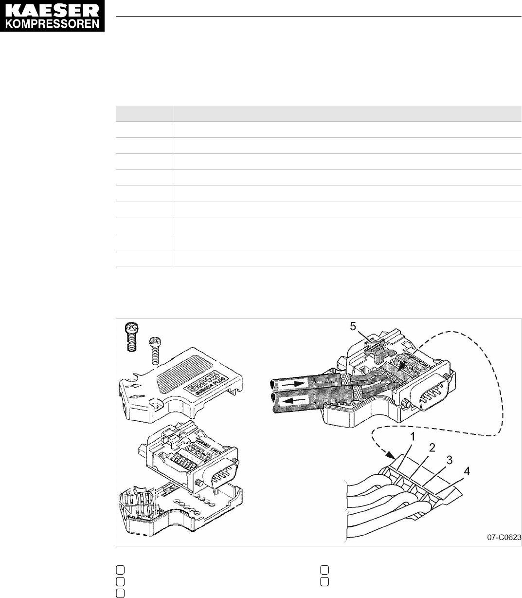
Establishing the electrical connection
Pin Assignment
1 Spare
2 Spare
3 PROFIBUS connection B
4 TTL signal RTS
5 Ground
6 +5 V for bus terminal
7 Spare
8 PROFIBUS connection A
9 Spare
Tab. 69 PROFIBUS DP pin connection
Interface plug wiring
Fig. 29 PROFIBUS plug wiring
1Terminal 1A
2Terminal 1B
3Terminal 2A
4Terminal 2B
5Slide switch, terminating resistor
8 Initial Start-up
8.10 Configuring the machine for master control
No.: 9_9450 07 USE
User Manual Controller
SIGMA CONTROL 2 SCREW FLUID ≥4.0.X 115
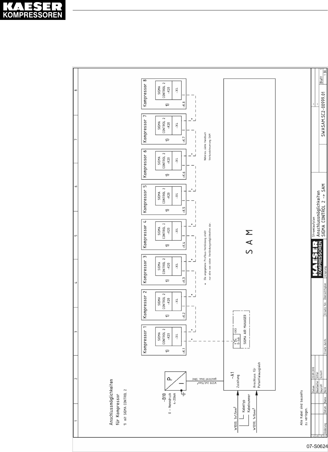
Electrical diagram example with SIGMA AIR MANAGER
Fig. 30 Electrical diagram example with SIGMA AIR MANAGER
8 Initial Start-up
8.10 Configuring the machine for master control
116 User Manual Controller
SIGMA CONTROL 2 SCREW FLUID ≥4.0.X No.: 9_9450 07 USE
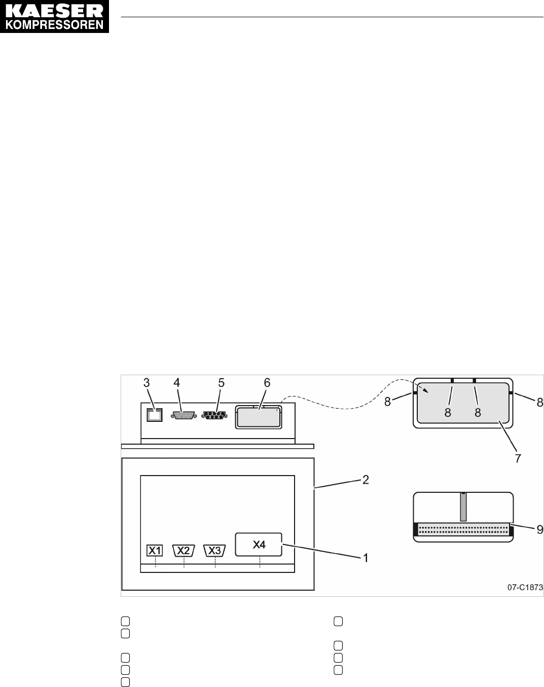
1. Connect the bus subscribers one after the other according to the pin assignment below.
2. Connect the screening to the plug housings at both ends.
3. Set the terminating resistor in the plug to ON for the first and last subscribers to the
PROFIBUS .
Result The terminals for the remaining bus conduit (2A/2B) are switched off.
8.10.3.1 Inserting the communication module
The SIGMA CONTROL 2 communication interface is sealed with a plastic cover when shipped
from the factory. Before you can insert the communication module in the X4 interface, you must
remove the plastic cover from the SIGMA CONTROL 2 . The designation of the interfaces is provi‐
ded on the rear of the SIGMA CONTROL 2.
Material Small screwdriver
Torx screwdriver, size 9
Precondition The machine is disconnected from the power supply.
The absence of voltage has been verified.
➤ Work with caution.
Removing the plastic cover
Fig. 31 Communication interface
1Designation of the interfaces
2Rear side of the SIGMA CONTROL 2 con‐
troller
3Ethernet interface X1
4IO BUS X2
5RS485–FC (USS interface) X3
6Communication interface X4 (customer in‐
terface)
7Plastic cover
8Fin
9Communication interface X4 without plastic
cover
1. Place the screwdriver next to the fin.
2. Insert the tip into the slot between the plastic cover and the enclosure of the
SIGMA CONTROL 2.
3. Press the screwdriver down until the fin breaks.
8 Initial Start-up
8.10 Configuring the machine for master control
No.: 9_9450 07 USE
User Manual Controller
SIGMA CONTROL 2 SCREW FLUID ≥4.0.X 117

4. Break the other fins in the same manner.
5. Remove the plastic cover 7.
Inserting and fixing the communication module
Align the communication module until both cable connectors are at the same height.
Precondition The plastic cover is removed.
Fig. 32 Inserting the communication module
1Bay, interface X4
2Cable connector, interface X4
3Guiding plate
4Recess, module bay
5Cable connector, communication module
6Communication module
7Front plate
1. Align the communication module 6.
2. Insert the communication module into the bay of interface X4 1 until it latches (see Fig. 32).
The module is correctly installed when its front plate 7 is seated solidly in the recess of the
module bay 4.
3. Use the Torx T9 screwdriver to screw in the fixing screws.
8.10.3.2 Activating operation via PROFIBUS
Overview:
■ Activating the communications module
■ Setting the slave address
■ Setting reaction for a communication malfunction
■ Activating the remote control
Precondition The communication module is plugged and screwed into the X4 interface.
The electrical connection to the bus master is made.
The machine's power supply is activated.
The machine is parametrized as a slave in the bus master.
The bus master is operational.
Fig. 33 Front plate of the PROFIBUScommunication module
1PROFIBUS communication module
2Operation
LED
3Status
LED
4PROFIBUSinterface
8 Initial Start-up
8.10 Configuring the machine for master control
118 User Manual Controller
SIGMA CONTROL 2 SCREW FLUID ≥4.0.X No.: 9_9450 07 USE

➤ Proceed as shown.
Activating the communications module
1. Select the 8.2
<Communication – Com-Module>
menu.
The
Com-Module
menu is displayed
2. Use «Up» or «Down» to select the
Com-Moduleactive
line.
3. Press «Enter» to switch into setting mode.
The
Com-Module active
check box flashes.
88psi 08:15AM 176° F
8.2 Com-Module Menu
Com-Module deactivated
__________________________________
Type None
Send/receive
Com-Module active : ☐ Active line
Reset : ☐
4. Press the «Up» key.
The check box is activated.
5. Press «Enter» to accept the setting.
The communication module is activated.
88psi 08:15AM 176° F
8.2 Com-Module Menu
No error
__________________________________
Type PROFIBUS
Send/receive
Com-Module active : ☑ Active line
Reset : ☐
6. Press «Escape» repeatedly to return to the main menu.
Setting the slave address
You only need to set the slave address for the communication with the
SIGMA AIR MANAGER.
The other parameters do not require adjustment. When connected to a
SIGMA AIR MANAGER, the slave address is determined as follows:
Compressor number used at SIGMA AIR MANAGER +102.
Precondition Password access level 2 is activated.
8 Initial Start-up
8.10 Configuring the machine for master control
No.: 9_9450 07 USE
User Manual Controller
SIGMA CONTROL 2 SCREW FLUID ≥4.0.X 119

1. Select the 8.2
<Communication – Com-Module>
menu.
The
Com-Module
menu is displayed
88psi 08:15AM 176° F
8.2 Com-Module Menu
Send/receive
Com-Module active : ☑ Active line
Reset : ☐
SlaveNo.: 103
·········
Communication error : ☑
2. Use «Up» or «Down» to select the
SlaveNo.
line.
88psi 08:15AM 176° F
8.2 Com-Module Menu
Send/receive
Com-Module active : ☑
Reset : ☐
SlaveNo.: 103 Active line
·········
Communication error : ☑
3. Press «Enter» to switch into setting mode.
The display for the slave address flashes.
4. Use «Up» or «Down» to set the slave address 104.
5. Press «Enter» to accept the setting.
The setting is applied.
88psi 08:15AM 176° F
8.2 Com-Module Menu
Send/receive
Com-Module active : ☑
Reset : ☐
SlaveNo.: 104 Active line
·········
Communication error : ☑ Monitoring for communication malfunction is active.
Result Slave address
104
is set.
Setting reaction for a PROFIBUS communication malfunction
Exchange of data with a PROFIBUS connection takes place in fixed cycles. The PROFIBUScon‐
nection can be monitored with the help of the cycle time:
The bus connection is considered to be interrupted if no data is exchanged between the bus mas‐
ter and the controller (as bus subscriber) after expiry of a set time period (time-out).
Time-out monitoring is activated. You may neither adjust nor deactivate time-out for
SIGMA AIR MANAGER.
8 Initial Start-up
8.10 Configuring the machine for master control
120 User Manual Controller
SIGMA CONTROL 2 SCREW FLUID ≥4.0.X No.: 9_9450 07 USE

After switching on the power supply, the communication malfunction can be suppressed tem‐
porarily.
Monitoring for communication malfunction can be deactivated if needed. For this purpose, the
Send
option must be selected for the data exchange.
■ Settings for SIGMA AIR MANAGER without SIGMA AIR CONTROL PLUS
─ Start: 30 seconds
■ Settings for SIGMA AIR MANAGER with SIGMA AIR CONTROL PLUS
─ Start: 40 seconds
1. Use «Up» or «Down» to select the
Communication error
line.
2. Press «Enter» to switch into setting mode.
The check box
Communication error
will flash.
88psi 08:15AM 176° F
8.2 Com-Module Menu
Reset : ☐
SlaveNo.: 104
·········
Communication error : ☐ Active line
Start td: 30 s
Timeout : 5 s ☑
3. Press the «Up» key.
The check box is activated.
The monitoring for communication malfunctions is active.
4. Use «Up» or «Down» to select the
Starttd
line.
88psi 08:15AM 176° F
Com-Module active : ☑
Reset : ☐
SlaveNo.: 104
·········
Communication error : ☑ Monitoring for communication malfunctions is active
Start td: 30 s Active line
Timeout : 5 s ☑
5. Press «Enter» to switch into setting mode.
The
00
seconds display flashes.
6. Use «Up» or «Down» to set the seconds.
7. Press «Enter» to accept the setting.
The setting is applied.
Activating the remote control
➤ Activate remote control see chapter 8.2.12.
Result SIGMA CONTROL 2 remote control is activated.
The bus master now remotely controls the SIGMA CONTROL 2.
8 Initial Start-up
8.10 Configuring the machine for master control
No.: 9_9450 07 USE
User Manual Controller
SIGMA CONTROL 2 SCREW FLUID ≥4.0.X 121

8.10.4 Configuring the master control of two machines in master/slave operation
Two machines with SIGMA CONTROL 2 work as master/slave in the same air network. The mas‐
ter controls the machine configured as a slave and provides the signal for the
pA
and
pB
setpoint
pressures.
Example: Two machines with different delivery quantities
Local operating mode of the master: Local mode
pA/pB Clock
.
■ Toggles between system pressure setpoints
pA
and
pB
by a clock program.
■ At peak load times, pressure is regulated to system setpoint pressure
pA
.
During periods of low air demand, pressure is regulated to system setpoint pressure
pB
(e. g.
at weekends).
■ The machine with the lesser air delivery is the slave.
In times with lower air demand, the machine with the smaller delivery is used more frequently.
Example: Two machines with equal delivery quantities
■ Local operating mode of the master: Local mode
pA/pB Cycle
.
(Toggles between system pressure setpoints
pA
and
pB
target pressure by a clock).
The timer ensures even loading of both machines. The system pressure setpoints are set the
same for both machines.
■ During timer period 1, the master regulates to
pA
and signals the slave for
pB
.
During timer period 2, the master regulates to
pB
and signals the slave to
pA
.
If two machines with SIGMA CONTROL 2 are to work in master-slave mode, their controllers
must have the same software version.
➤ Follow the configuration steps as described in table 70:
Controller Procedure Chapter
Both Making the electrical connection 8.10.4.1
Both Set the system pressure setpoints for both,
pA
and
pB
. The pressure
for switching points
pA
and
pB
is measured directly at the compressor.
Pressure losses in the network do not need to be taken into account.
8.10.4.2 and
8.10.4.3
Master Either set up switching times for the clock program 8.10.4.2
Or, set switching times for the clock 8.10.4.2
Master Set the type of LOAD control (clock program or clock) in local mode 8.10.4.2
Slave Set remote mode
pA/pB SC2
8.10.4.3
Slave Activate the «Remote control» key 8.10.4.3
Both Set IP addresses for Ethernet 8.10.4.2 and
8.10.4.3
Both Activate controller as master or slave 8.10.4.2 and
8.10.4.3
Tab. 70 Master-slave configuration procedure
8.10.4.1 Making the electrical connection
You need the following accessories to create the network connection with SIGMA NETWORK or
Ethernet:
8 Initial Start-up
8.10 Configuring the machine for master control
122 User Manual Controller
SIGMA CONTROL 2 SCREW FLUID ≥4.0.X No.: 9_9450 07 USE

■ SIGMA NETWORK cable (7.9679.0) or Ethernet cable with a maximum connection length of
328 ft. each.
■ For each machine with SIGMA CONTROL 2:
─ Retrofit kit LAN RJ45 (7.5250.01870)
■ For connecting the machines to a network (LAN) or switch:
─ 2x RJ45 plug (7.7628.1)
➤ Make the electrical connection according to the local condition. For more information, see the
installation manual for the Retrofit kit LAN RJ45 (7.5250.01870)
Installing the Ethernet cable
Use a cross-link Ethernet cable for the direct connection of two machines.
Fig. 34 Direct connection of two SIGMA CONTROL 2
1Controller machine 1 (Master mode)
2Ethernet interface X1
3Ethernet cable, cross-link
4Controller machine 2 (Slave mode)
5Ethernet interface X1
➤ Install the Ethernet cable between the two machines.
For connecting the machines to a network (LAN) or switch (when using KAESER CONNECT for
example).
➤ Install the Ethernet cable from each machine to the LAN connection or switch.
Connecting the Ethernet cable with the machine
For each machine:
1. Insert the Ethernet cable into the machine and the machine's control cabinet, using an EMC
connection.
2. Feed the Ethernet cable through the cable ducts to SIGMA CONTROL 2. Use the wiring path
in the 24V range (blue wiring) of the ducts.
8 Initial Start-up
8.10 Configuring the machine for master control
No.: 9_9450 07 USE
User Manual Controller
SIGMA CONTROL 2 SCREW FLUID ≥4.0.X 123

3. Install the Ethernet bus plug at the cable end.
4. Push the bus plug into the Ethernet interface X1 of the SIGMA CONTROL 2 until it latches.
For connecting the machines to a network (LAN) or switch
Connect the Ethernet cable for each machine to the LAN connection or switch.
1. Install the Ethernet bus plug to the cable end.
2. Push the bus plug into the LAN socket until it latches.
8.10.4.2 Configure the controller of machine 1 as master
Precondition The electrical connection is made.
Password access level 2 is activated.
Setting the switching points pA and pB
1. Select the 5.2.2
<Configuration – Pressure control – Pressure settings>
menu.
The
pA
line is displayed.
2. Press «Enter» to switch into setting mode.
The value for
pA
flashes.
88psi 08:15AM 176° F
5.2.2 Pressure settings Menu
Setpoint pressure
pA SP: 123psi ¦ SD: −7.3psi Active line
pB SP: 119psi ¦ SD: −7.3 psi
·········
System pressure low ☐
↓< 72.5psi ¦ SD: 7.2psi
3. Use «Up» or «Down» to set the
pA
value.
4. Press «Enter» to accept the setting.
The setting is applied.
5. Press «Down».
The
pB
line is displayed.
6. Adjust the value for
pB
in the same manner, If necessary,
Setting the times
SIGMA CONTROL 2 provides the following options for selecting times:
■ 1: Clock program
■ 2: Timer
1. Decide your desired method.
2. Follow the instructions below for the settings required.
8 Initial Start-up
8.10 Configuring the machine for master control
124 User Manual Controller
SIGMA CONTROL 2 SCREW FLUID ≥4.0.X No.: 9_9450 07 USE

Alternative 1: Setting the clock program
Precondition The electrical connection is made.
Password access level 2 is activated.
➤ Setting the target pressure change with a clock program; see chapter 8.9.2.
Alternative 2: Setting the timer
Precondition The electrical connection is made.
Password access level 2 is activated.
1. Setting clock periods
pA
and
pB
see chapter 8.9.3.1
2. Setting the starting time for
pA
or
pB
; see chapter 8.9.3.2.
Master IP configuration
If the controllers of both machines are linked directly, they must be given different IP addresses.
Example:
■ IP address of the machine 1 controller (Master mode): 169.254.100.101
■ IP address of the machine 2 controller (Slave): 169.254.100.102
Precondition The electrical connection is made.
Password access level 2 is activated.
1. IP address set for the master: For instructions, see chapter 8.2.13, IP address for the above
example.
The IP address of machine 1 (master) is set correctly.
2. Open the 8.1.2.1
<Communication – Ethernet/SIGMA NETWORK – Connections – SIGMA
CONTROL 2>
menu.
3. Use «Up» or «Down» to select the
Mode
line.
4. Press «Enter» to switch into setting mode.
The setting mode is active.
88psi 08:15AM 176° F Header
8.1.2.1 SIGMA CONTROL 2 Menu
Status Run 0 ¦Error 0
__________________________________
Mode : Master Active line
Port : 2.001
·········
Communication partner
5. Use «Up» or «Down» to set Machine 1
Master
operating mode.
6. Press «Enter» to accept the setting.
The setting is applied.
7. Use «Up» or «Down» to select the
IP address
line.
8. Press «Enter» to switch into setting mode.
The setting mode is active.
8 Initial Start-up
8.10 Configuring the machine for master control
No.: 9_9450 07 USE
User Manual Controller
SIGMA CONTROL 2 SCREW FLUID ≥4.0.X 125

9. Set the IP address of the communication partner (slave, see above example).
10. Press «Enter» to accept the setting.
The IP address of machine 2 (slave) is set correctly.
The setting is applied.
Result The controller of machine 1 is set as master.
8.10.4.3 Configuring the machine 2 controller as slave
Precondition The electrical connection is made.
Password access level 2 is activated.
Setting the switching points pA and pB
1. Open the 5.2.2
<Configuration – Pressure control – Pressure settings>
menu.
The
pA
line is displayed.
2. Press «Enter» to switch into setting mode.
The value for
pA
flashes.
88psi 08:15AM 176° F
5.2.2 Pressure settings Menu
Setpoint pressure
pA SP: 123psi ¦ SD: −7.3psi Active line
pB SP: 119psi ¦ SD: −7.3 psi
·········
System pressure low ☐
↓< 72.5psi ¦ SD: 7.2psi
3. Use «Up» or «Down» to set the
pA
value.
4. Press «Enter» to accept the setting.
The setting is applied.
5. Press «Down».
The
pB
line is displayed.
6. If necessary, adjust the value for the
pB
switching differential in the same manner.
Activating the remote control
➤ Activating Remote control see chapter 8.2.12.
Result SIGMA CONTROL 2 Remote control is activated.
Setting the remote operating mode
Precondition The electrical connection is made.
Password access level 2 is activated.
1. Open the 5.2.3
<Configuration – Pressure control – Load control>
menu.
2. Use «Up» or «Down» to select the
Remote mode
line.
8 Initial Start-up
8.10 Configuring the machine for master control
126 User Manual Controller
SIGMA CONTROL 2 SCREW FLUID ≥4.0.X No.: 9_9450 07 USE

3. Press «Enter» to switch into setting mode.
The setting mode is active.
88psi 08:15AM 176° F
5.2.3 Load control Menu
Local mode: pA/pB Cycle
Remote mode: pA/pB SC2 Active line, current operating mode
__________________________________
▶1 pA/pB Clock
·········
pA/pB Cycle
4. Use «Up» or «Down» to set the
pA/pB SC2
input.
5. Press «Enter» to accept the setting.
The setting is applied.
Specifying machine 2 with Slave IP address
If the controllers of both machines are linked directly, they must be given different IP addresses.
Example:
■ IP address of the machine 1 controller (Master mode): 169.254.100.101
■ IP address of the machine 1 controller (Slave mode): 169.254.100.102
Precondition The electrical connection is made.
Password access level 2 is activated.
1. IP address set for the master: For instructions, see chapter 8.2.13, IP address for the above
example.
The IP address of machine 2 (slave) is set correctly.
2. Open the 8.1.2.1
<Communication – Ethernet/SIGMA NETWORK – Connections – SIGMA
CONTROL 2>
menu.
3. Use «Up» or «Down» to select the
Mode
line.
4. Press «Enter» to switch into setting mode.
The setting mode is active.
5. Use «Up» or «Down» to set Machine 2
Slave
operating mode.
6. Press «Enter» to accept the setting.
The setting is applied.
7. Use «Up» or «Down» to select the
IP address
line.
8. Press «Enter» to switch into setting mode.
The setting mode is active.
9. Set the IP address of the communication partner (master, see above example).
10. Press «Enter» to accept the setting.
The setting is applied.
Result The controller of machine 2 is set as slave.
8 Initial Start-up
8.10 Configuring the machine for master control
No.: 9_9450 07 USE
User Manual Controller
SIGMA CONTROL 2 SCREW FLUID ≥4.0.X 127
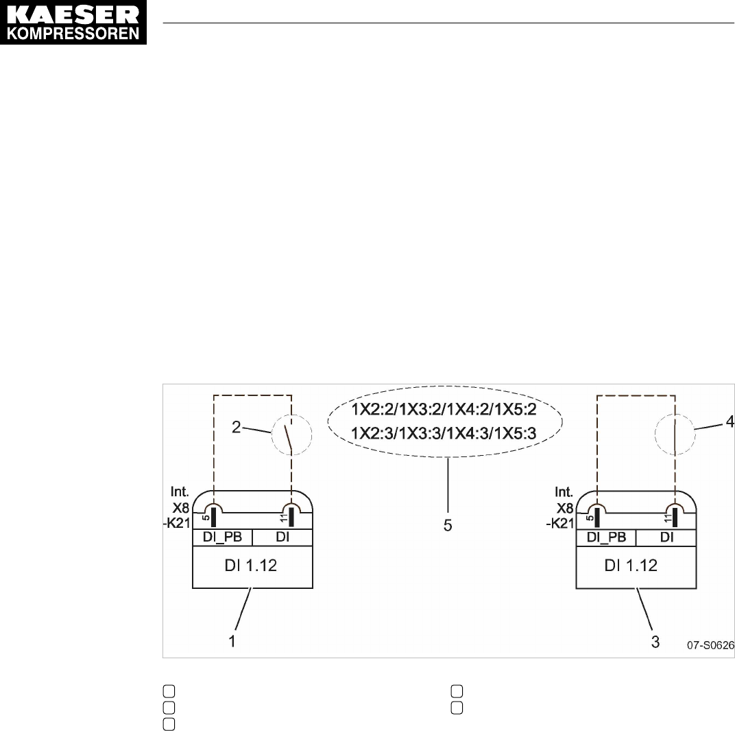
8.10.5 Configuring master control using the LOAD remote contact (e.g.,
SIGMA AIR MANAGER BASIC)
Overview
■ Making the electrical connection for LOAD remote contact
■ Setting the LOAD remote contact operating mode and assigning the input
■ Adjusting the pressure increase
pE
, if necessary
■ Activating the «Remote control» key
➤ Configure master control as described below.
8.10.5.1 Making the electrical connection for LOAD remote contact (excerpt)
Machine (example)
Fig. 35 LOAD remote contact
1Electrical connection DI 1.12
2LOAD remote contact open (IDLE)
3Electrical connection DI 1.12
4LOAD remote contact closed (LOAD)
5SIGMA AIR MANAGER BASIC contacts
➤ Establish the electrical connection for DI 1.12 according to the diagram.
8.10.5.2 Setting the LOAD remote contact operating mode and assigning the input for LOAD remote contact
Precondition Password access level 2 is activated.
Setting the LOAD remote contact operating mode
1. Select the 5.2.3
<Configuration – Pressure control – Load control>
menu.
2. Use «Up» or «Down» to select the
Remote mode
line.
8 Initial Start-up
8.10 Configuring the machine for master control
128 User Manual Controller
SIGMA CONTROL 2 SCREW FLUID ≥4.0.X No.: 9_9450 07 USE
3. Press «Enter» to switch into setting mode.
The currently active operating mode
Remote mode
flashes.
88psi 08:15AM 176° F
5.2.3 Load control Menu
Local mode: pA/pB Cycle
Remote mode: Load RC Active line
__________________________________
▶1 pA/pB Clock
·········
pA/pB Cycle
4. Use «Up» or «Down» to set the
Load RC
input.
5. Press «Enter» to accept the setting.
The LOAD remote contact operating mode is set.
Assigning the input for LOAD remote contact
The input for the LOAD remote contact is pre-assigned.
Setting is only necessary if you deliberately want to use a different input.
1. Use «Up» or «Down» to select the
Load RC
line.
2. Press «Enter» to switch into setting mode.
The
DI
display flashes.
88psi 08:15AM 176° F
5.2.3 Load control Menu
pA/pB DO DOR1.03 ☐
Logic : +
·········
Load RC DI1.13 ok ☑ Active line; standard DI 1.13
Logic : +
loc.-load RC DI1.09 ☐
3. Use «Up» or «Down» to select the input for the LOAD remote contact.
4. Press «Enter» to accept the setting.
The setting is applied.
5. Press the «Right» arrow.
6. Press «Enter».
The check box
Load RC
will flash.
7. Press «Up» key.
The check box is activated.
8. Press «Enter».
ok
is displayed to the left of the check box.
The operating mode is set.
8 Initial Start-up
8.10 Configuring the machine for master control
No.: 9_9450 07 USE
User Manual Controller
SIGMA CONTROL 2 SCREW FLUID ≥4.0.X 129

8.10.5.3 Setting the SD switching differential of the pressure increase
➤ Set the SD switching differential of the pressure increase as described in chapter 8.4.2.3.
Further information Detailed information on the pressure parameters is provided in chapter 8.4.2.
8.10.5.4 Activating the remote control
➤ Activate remote control see chapter 8.2.12.
Result SIGMA CONTROL 2 remote control is activated.
8.10.6 Configuring the master control with local/LOAD remote contact
Overview
■ Making the electrical connection
■ Setting the local/LOAD remote contact operating mode and assigning the input
■ Setting local operating mode, if necessary
■ Activating the «Remote control» key
➤ Configure master control as described below.
8.10.6.1 Making the electrical connection
Use the input “Controller On for the "alarm machine X" message (DOR1.03) to prevent line
breaks!
➤ Wire the "motor running” and "Controller on” (DOR1.03) messages from the compressor
to the MVS 8000.
■ Contact A open: SIGMA CONTROL 2controls with
pB
system setpoint pressure.
■ Contact A closed: SIGMA CONTROL 2 controls via external LOAD mode contact.
■ DI 1.13: LOAD/IDLE external.
■ DI 1.09: LOAD control – switchover local/LOAD remote contact.
8 Initial Start-up
8.10 Configuring the machine for master control
130 User Manual Controller
SIGMA CONTROL 2 SCREW FLUID ≥4.0.X No.: 9_9450 07 USE
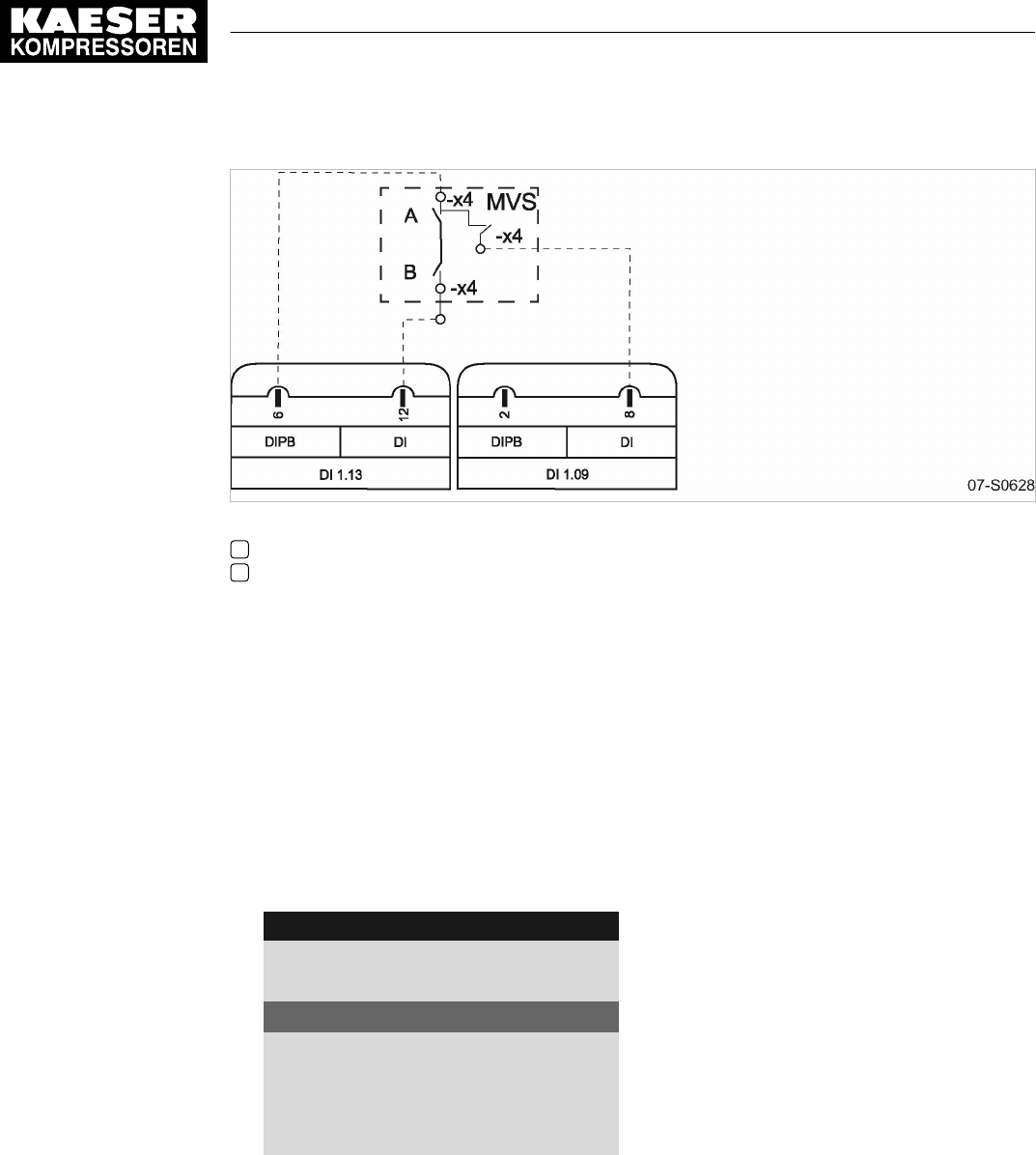
Fig. 36 Wiring diagram for local/LOAD remote contact:
AChangeover between automatic and manual modes
BLOAD/IDLE contact
➤ Make the electrical connection according to the diagram.
8.10.6.2 Setting the local/LOAD remote contact operating mode and assigning the input
Precondition Password access level 2 is activated.
Setting local/LOAD remote contact operating mode
1. Select the 5.2.3
<Configuration – Pressure control – Load control>
menu.
2. Use «Up» or «Down» to select the
Remote mode
line.
3. Press «Enter».
The currently active operating mode
Remote mode
flashes.
88psi 08:15AM 176° F
5.2.3 Load control Menu
Local mode: pA/pB Cycle
Remote mode: loc.-load RC Active line
__________________________________
▶1 pA/pB Clock
·········
pA/pB Cycle
4. Use «Up» or «Down» to set the
loc.-load RC
input.
5. Press «Enter».
The local/LOAD remote contact operating mode is set.
Assigning an input for the local/LOAD remote contact for switching the pressure control
1. Use «Up» or «Down» to select the
loc.-load RC
line.
8 Initial Start-up
8.10 Configuring the machine for master control
No.: 9_9450 07 USE
User Manual Controller
SIGMA CONTROL 2 SCREW FLUID ≥4.0.X 131
2. Press «Enter».
The
DI
display flashes.
88psi 08:15AM 176° F
5.2.3 Load control Menu
pA/pB DO DOR1.03 ☐ No input assigned
Logic : +
·········
Load RC DI1.13 ok ☑
Logic : +
loc.-load RC DI1.09 ☑ Active line
3. Use «Up» or «Down» to select a new input for local/LOAD remote contact.
4. Press «Enter».
The input for local/LOAD remote contact is assigned.
8.10.6.3 Setting local operating mode pB
The
pB
system setpoint pressure is normally set for local operation.
➤ When setting the
pB
system setpoint pressure, bear in mind that, under certain circum‐
stances, more than one compressor may be operating in local mode (see section 8.4 for
adjusting the system setpoint pressure).
Precondition Password access level 2 is activated.
1. Select the 5.2.3
<Configuration – Pressure control – Load control>
menu.
2. Use «Up» or «Down» to select the
Local mode
line.
3. Press «Enter» to switch into setting mode.
The operating mode display flashes.
88psi 08:15AM 176° F
5.2.3 Load control Menu
Local mode : pB Active line, current operating mode
Remote mode: loc.-load RC
__________________________________
▶1 pA/pB Clock
·········
pA/pB Cycle
4. Use «Up» or «Down» to set the
pB
input.
5. Press «Enter» to accept the setting.
The setting is applied.
6. Adjust the
pB
system setpoint pressure, if necessary (see section 8.4).
The local operating mode
pB
is set.
8.10.6.4 Activating the remote control
➤ Activate remote control see chapter 8.2.12.
Result SIGMA CONTROL 2 remote control is activated.
8 Initial Start-up
8.10 Configuring the machine for master control
132 User Manual Controller
SIGMA CONTROL 2 SCREW FLUID ≥4.0.X No.: 9_9450 07 USE

8.10.6.5 Assigning an input for the LOAD remote contact for switching the pressure control
Precondition Password access level 2 is activated.
1. Open the 5.2.3
<Configuration – Pressure control – Load control>
menu.
2. Use «Up» or «Down» to select the
Load RC
line.
3. Press «Enter» to switch into setting mode.
The
DI
display flashes.
88psi 08:15AM 176° F
5.2.3 Load control Menu
pA/pB RC DI1.05 ☐
Logic : +
pA/pB DO DOR1.04 ☐
Logic : +
·········
Load RC DI1.13 ok ☑ Active line
4. Use «Up» or «Down» to select the input for the LOAD remote contact.
5. Press «Enter» to accept the setting.
The input for LOAD remote contact is assigned.
8.10.7 Setting the setpoint pressure pre-selection via remote contact
The signal to changeover from setpoint pressure
pA
to setpoint pressure
pB
comes from an input
contact. If there is a signal at the input then system pressure is regulated on setpoint pressure
pB
.
Overview
■ Setting up remote contact mode pA/pB
■ Assigning the remote contact input
■ Activating the remote control
➤ Configure the setpoint pressure pre-selection as described.
8.10.7.1 Setting up remote contact mode pA/pB
Precondition The electrical connection is made.
Password access level 2 is activated.
1. Open the 5.2.3
<Configuration – Pressure control – Load control>
menu.
2. Use «Up» or «Down» to select the
Remote mode
line.
8 Initial Start-up
8.10 Configuring the machine for master control
No.: 9_9450 07 USE
User Manual Controller
SIGMA CONTROL 2 SCREW FLUID ≥4.0.X 133

3. Press «Enter».
The currently active operating mode flashes.
88psi 08:15AM 176° F
5.2.3 Load control Menu
Local mode: pB
Remote mode : pA/pB RC Active line
__________________________________
▶1 pA/pB Clock
·········
pA/pB Cycle
4. Use «Up» or «Down» to set the
pA/pB RC
input.
5. Press «Enter».
Result The
pA/pB RC
operating mode is set.
8.10.7.2 Assigning the remote contact input
A spare input can be found in the machine circuit diagram.
1. Use «Up» or «Down» to select the
pA/pB RC
line.
2. Press «Enter».
The
DI
display flashes.
88psi 08:15AM 176° F
5.2.3 Load control Menu
pA/pB RC DI1.05 ☑ Active line
Logic : +
pA/pB DO DOR1.04 ☐
Logic : +
·········
Load RC DI1.13 ok ☑
3. Use «Up »or «Down» to set the
DI
input.
4. Press «Enter».
Result The input for remote contact has now been assigned.
8.10.7.3 Activating the remote control
➤ Activating the remote control see chapter 8.2.12.
Result SIGMA CONTROL 2 remote control is activated.
8.10.8 Configuring master control of compressors regulated by pressure switch
➤ Configure the master control as described below.
8 Initial Start-up
8.10 Configuring the machine for master control
134 User Manual Controller
SIGMA CONTROL 2 SCREW FLUID ≥4.0.X No.: 9_9450 07 USE

8.10.8.1 Configuring master control via floating relay contact
Requirement:
A machine with SIGMA CONTROL 2 (e.g. series BSD) and a conventional machine without
SIGMA CONTROL 2 of the same capacity are to run in sequence as base load or peak load ma‐
chines.
Proposal:
■ Set/adjust the clock program or clock on SIGMA CONTROL 2.
■ Select local mode with time control pA/pB Clock or clock pA/pB Cycle.
■ Set the system setpoint pressures pA and pB analogous to the required values. They must be
identical to the pressure switch settings on the machine without SIGMA CONTROL 2.
■ To make the system setpoint pressure changeover between the two machines possible, a
floating relay contact must be assigned to the selected local operating mode. An auxiliary con‐
tactor can be energized via this contact to activate the pressure switches for pA and pB on the
compressor without SIGMA CONTROL 2. See the example wiring diagram below.
Overview
■ Making the electrical connection
■ Setting the system setpoint pressure pA and pB.
■ Setting operating mode in local operating mode
■ Assigning the floating relay contact
■ Setting local operating mode
Making the electrical connection
■ Contact A open: SIGMA CONTROL 2 controls with system setpoint pressure pB
■ Contact A closed: SIGMA CONTROL 2 controls with system setpoint pressure pA
■ B 1.1: Pressure switch for system setpoint pressure pB
■ B 1.2: Pressure switch for system setpoint pressure pA
8 Initial Start-up
8.10 Configuring the machine for master control
No.: 9_9450 07 USE
User Manual Controller
SIGMA CONTROL 2 SCREW FLUID ≥4.0.X 135

07-S0629
A
-K3 A1
A2
Fig. 37 Machine with pressure switch regulation
Afloating relay contact SIGMA CONTROL 2
➤ Make the electrical connection according to the diagram.
Setting the system setpoint pressure pA and pB.
Precondition Password access level 2 is activated.
The electrical connection is made.
1. Select the
<5.2.2 – Pressure control – Pressure settings>
menu (see chapter 8.4.1).
2. Use «Up» or «Down» to select the
pASP
line.
3. Press «Enter» to switch into setting mode.
The setting mode is active.
The
Setpoint pressure pA
display flashes.
88psi 08:15AM 176° F
5.2.2 Pressure settings Menu
Setpoint pressure
pA SP: 123psi ¦ SD: −7.3psi Active line
pB SP: 119psi ¦ SD: −7.3 psi
·········
System pressure low ☐
↓< 72.5psi ¦ SD: 7.2psi
4. Use «Up» or «Down» to set the value for
pA
.
5. Press «Enter» to accept the setting.
The setting is applied.
6. Adjust the value for the
SD
switching differential in the same way, if necessary.
7. Adjust the value for
pB/SD
in the same manner, if necessary.
8. Press «Esc» repeatedly to leave this menu.
8 Initial Start-up
8.10 Configuring the machine for master control
136 User Manual Controller
SIGMA CONTROL 2 SCREW FLUID ≥4.0.X No.: 9_9450 07 USE

Configuring local mode
➤ Set the clock program or clock as described in section 8.9.
Assigning the floating relay contact (activate)
Precondition Password access level 2 is activated.
The electrical connection made (select spare contact from the machine's electrical diagram).
1. Select the 5.2.3
<Configuration – Pressure control – Load control>
menu.
2. Use «Up» or «Down» to select the
pA/pB DO
line.
88psi 08:15AM 176° F
5.2.3 Load control Menu
pA/pB RC DI1.10 ☐
Logic : +
pA/pB DO DOR1.03 ☐ Active line, no output assigned
Logic : +
·········
Load RC DI1.03 ok ☑
3. Press «Enter» .
The setting mode is active.
4. Use «Up» or «Down» to set the required output.
5. Press «Enter».
The setting is applied.
Result This output can now be used for the changeover between the two pressure switches.
Setting local mode
Precondition Password access level 2 is activated.
1. Select the 5.2.3
<Configuration – Pressure control – Load control>
menu.
2. Use «Up» or «Down» to select the
Local mode
line.
88psi 08:15AM 176° F
5.2.3 Load control Menu
Local mode: pA Active line, current operating mode
Remote mode: pA
__________________________________
▶1 pA/pB Clock
·········
pA/pB Cycle
3. Press «Enter» to switch into setting mode.
The setting mode is active.
4. Use «Up» or «Down» to set the
pA/pB Clock or pA/pB Cycle
operating mode.
5. Press «Enter» to accept the setting.
The setting is applied.
8 Initial Start-up
8.10 Configuring the machine for master control
No.: 9_9450 07 USE
User Manual Controller
SIGMA CONTROL 2 SCREW FLUID ≥4.0.X 137

8.10.8.2 Configuring the master control without an electrical connection
Requirement:
A high-capacity machine with SIGMA CONTROL 2 (e. g. BSD) is to work as base load machine. A
second machine (e.g., SK) without SIGMA CONTROL 2 is to supply air in times of low demand.
Proposal:
■ Select the system setpoint pressures pA and pB of the BSD machine for the switching point of
the SK machine's pressure switch to be in between. When pB is activated for the periods of
low demand, the SK machine automatically functions as the base load machine.
■ Set the required values for a clock program on SIGMA CONTROL 2.
■ Select local mode pA/pB SC2Clk.
■ Activate the compressor timer.
Function diagram
Period t1–t7: high compressed air demand Period t8–t14: low compressed air demand
t1
Air demand rises.
System pressure pNloc drops.
t8:
Air demand rises.
System pressure pNloc drops.
t2
BSD switches to LOAD.
t9:
SK switches to LOAD.
t3:
System setpoint pressure pA reached.
BSD switches to IDLE.
t10:
System setpoint pressure pB reached.
SK switches to IDLE.
t4:
BSD switches to LOAD.
Air demand not covered.
t11:
BSD switches to LOAD.
Air demand not covered.
t5:
SK also switches to LOAD.
System pressure pNloc begins to rise.
t12:
SK switches to LOAD.
System pressure pNloc begins to rise.
t6:
SK switches to IDLE.
t13:
SK switches to IDLE.
t7:
BSD switches to IDLE.
t14:
BSD switches to IDLE.
Tab. 71 Function diagram
8 Initial Start-up
8.10 Configuring the machine for master control
138 User Manual Controller
SIGMA CONTROL 2 SCREW FLUID ≥4.0.X No.: 9_9450 07 USE
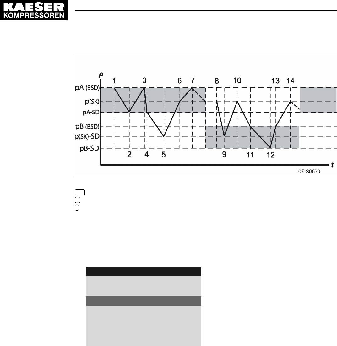
Fig. 38 Function diagram
SD Switching differential
pPressure
tTime
Setting the system setpoint pressure pA and pB
Precondition Password access level 2 is activated.
1. Select the
<5.2.2 – Pressure control – Pressure settings>
menu (see chapter 8.4.1).
2. Use «Up» or «Down» to select the
pASP
line.
88psi 08:15AM 176° F
5.2.2 Pressure settings Menu
Setpoint pressure
pA SP: 123psi ¦ SD: −7.3psi Active line
pB SP: 119psi ¦ SD: −7.3 psi
·········
System pressure low ☐
↓< 72.5psi ¦ SD: 7.2psi
3. Press «Enter» to switch into setting mode.
The
pA
display flashes.
4. Use «Up» or «Down» to set the
pA
value.
5. Press «Enter» to accept the setting.
The setting is applied.
6. If necessary, adjust the value for SD/ in the same manner.
7. If necessary, adjust the value for
pB/SD
in the same manner.
8. Press «Esc» repeatedly to leave this menu.
Configuring the clock program
➤ Configure the clock program as described in chapter 8.9.2.
8 Initial Start-up
8.10 Configuring the machine for master control
No.: 9_9450 07 USE
User Manual Controller
SIGMA CONTROL 2 SCREW FLUID ≥4.0.X 139

8.10.9 Examples of time settings for equal overall load
Requirement:
Two machines of the same capacity are to be equally loaded. Versions A, B and C describe the
different possibilities of achieving this requirement.
A detailed description for configuring a clock or timing program can be found in Chapter 8.9.
Variant A: Daily switch between system setpoint pressure pA and system setpoint pressure pB af‐
ter 24 hours
The compressors start with a system setpoint pressure
pB
at 0:00 hours. A timer triggers the
switch between system setpoint pressure
pA
and system setpoint pressure
pB
(local operating
mode:
pA/pB Cycle
local mode).
Precondition The setpoint pressure
pA
/
pB
is configured the same for both machines.
➤ Establish a cycle with the following switching points:
■ Cycle time
pA
: 24 h
■ Cycle time
pB
: 24 h
■ Start
pB
: 00:00AM
Variant B: Equal duty cycle during the day
A timer triggers the switch between system setpoint pressure
pA
and system setpoint pressure
pB
(local operating mode
pA/pB Clock
.
Precondition The system setpoint pressure
pA
/
pB
is configured the same for both machines.
➤ The clock program is set up using the following switching points:
No.: Weekday Time Network nominal pressure
01 Mon-Sun 00:00AM
pA
On
02 Mon-Sun 06:30AM
pB
On
03 Mon-Sun 12:00PM
pA
On
04 Mon-Sun 05:00PM
pB
On
Tab. 72 Example for a clock program for equal duty cycling during the day
Variant C: Equal duty cycle during the week
A timer triggers the switch between system setpoint pressure
pA
and system setpoint pressure
pB
(local operating mode:
pA/pB SC2Clk
).
Precondition The system setpoint pressure
pA
/
pB
is configured the same for both machines.
➤ The clock program is set up using the following switching points:
No.: Weekday Time Network nominal pressure
01 Mon 00:00AM
pA
On
02 Mon 09:00PM
pB
On
03 Tue 05:00PM
pA
On
8 Initial Start-up
8.10 Configuring the machine for master control
140 User Manual Controller
SIGMA CONTROL 2 SCREW FLUID ≥4.0.X No.: 9_9450 07 USE

No.: Weekday Time Network nominal pressure
04 Wed 03:00PM
pB
On
05 Thu 12:00PM
pA
On
06 Fri 09:00AM
pB
On
07 Sat 06:30AM
pA
On
08 Sun 03:00AM
pB
On
Tab. 73 Example for a clock program for equal duty cycling during the week
8.11 Configuring input and output signals
The controller's analog and digital inputs and outputs can be used for customized messages and/or
other functions.
This chapter deals with the various options in the following sections:
■ 8.11.1: Outputting operational states of machine on digital outputs
■ 8.11.2: Outputting input signals on the display
■ 8.11.3: Outputting measured values on the display
The controller only allows assignment of spare inputs and outputs.
If an occupied input or output is assigned this will be rejected by the controller.
When delivered from the factory, the outputs DO0.3 to DO0.5 are available for assignment.
Further spare outputs can be found in the machine circuit diagram.
➤ Configure the inputs and outputs as described in the following.
8.11.1 Outputting important operational states of the machine
Important operational machine states can be made available as digital signals via floating contacts.
Each output can be assigned only once.
The following messages can be output:
Message Explanation Output
Controller on Controller is powered up
Compressor on The machine is switched on
Motor running Compressor motor running
IDLE The machine is running in IDLE mode
ON LOAD The machine is running in LOAD mode
Group alarm Fault has occurred
Group warning Warning message has appeared
Remote mode Remote mode is activated
Clock active Clock is activated
Clock contact The clock contact is closed
EMERGENCY STOP The EMERGENCY STOP push button has been pressed
Tab. 74 Assigned output signals
8 Initial Start-up
8.11 Configuring input and output signals
No.: 9_9450 07 USE
User Manual Controller
SIGMA CONTROL 2 SCREW FLUID ≥4.0.X 141

8.11.1.1 DO functions menu
The requested message can be assigned to a free digital output (DOR orDOT).
Precondition Password access level 2 is activated.
1. Select the 5.7.1
<Configuration – I/O periphery – DO functions>
menu.
A list of available messages and their assigned outputs is displayed.
88psi 08:15AM 176° F
5.7.1 DO functions Menu
Controller on Active line
DOR1.05 ☐ ¦ Logic : +
DOT1.02 ☐ ¦ Logic : +
Compressor on
DOR1.03 ☐ ¦ Logic : +
DOT1.02 ☐ ¦ Logic : +
8.11.1.2 Assigning a message to an output
1. Select the required message with the «Up» or «Down» keys.
2. Press the «Down» key once.
Output DOR has been selected.
3. Press «Down» twice.
Output DOT has been selected.
4. Press «Enter».
The output of the selected message flashes.
88psi 08:15AM 176° F
5.7.1 DO functions Menu
Controller on
DOR1.05 ok ☑ ¦ Logic : + Active line with assigned output
DOT1.02 ☐ ¦ Logic : +
Compressor on
DOR1.03 ☐ ¦ Logic : +
DOT1.02 ☐ ¦ Logic : +
5. Select a free output with the «Up» or «Down» key.
6. Press «Enter».
The setting is applied.
7. Press the «Right» key.
8. Press «Enter».
The check box will flash.
9. Press «Up» key.
The check box associated to the output is activated.
10. Press «Enter».
If the message is correctly assigned to the output and activated,
ok
is displayed.
11. If necessary, set the
Logic
option.
8 Initial Start-up
8.11 Configuring input and output signals
142 User Manual Controller
SIGMA CONTROL 2 SCREW FLUID ≥4.0.X No.: 9_9450 07 USE

Result A message about the operational state is now sent via the assigned output.
You are missing an organized display of assigned output signals?
➤ Enter the selected output in table 74.
8.11.2 Output input signals on the display
As well as the defined fault and warning messages there are 6 additional freely selectable input
signals that can be used to display messages. A list of the alarm and warning messages is provi‐
ded in chapters 10.2 and 10.3. Information on spare inputs is given in the machine circuit diagram.
An input signal can be classified as either an alarm, a warning or an operational message. To sup‐
press any possible contact bounce or similar problems, the input signal can be delayed by an ad‐
justable period. This ensures that the signal must be apparent for a minimum period before it can
be processed as a message.
If an input signal is classified as an alarm, the controller goes into the alarm state and shuts
down the machine.
Overview
Use the
External messages
menu for specifying the settings.
■ Entering the message text
■ Assigning and activate the input
■ Setting the time delay
■ Setting the logic
■ Assigning and activate the output
■ Selecting the message type
■ Activating the message.
8.11.2.1 External messages menu
Precondition The electrical connection has been made.
Access level 2 is activated.
1. Open the 5.7.3
<Configuration – I/O periphery – External messages>
menu.
The
External messages
menu is displayed
88psi 08:15AM 176° F
5.7.3 External messages Menu
▶1 External message 1 Active line with external message No. 1
▶2 External message 2
▶3 External message 3
▶4 External message 4
▶5 External message 5
▶6 External message 6
8.11.2.2 Entering the message text
In the below example we select
External message 1
.
1. Use «Up» or «Down» to select the
External message 1
line.
8 Initial Start-up
8.11 Configuring input and output signals
No.: 9_9450 07 USE
User Manual Controller
SIGMA CONTROL 2 SCREW FLUID ≥4.0.X 143

2. Press «Enter».
The
External message 1
menu is displayed.
88psi 08:15AM 176° F
5.7.3.1 External message 1 Menu
External message 1 Active line, message text
DI1.11 ☐ No input assigned
td: 0 s ¦ Logic + Logic
DOR1.04 ☐
Warning ☑ Message type (operational, alarm, warning)
3. Press «Enter».
The cursor is located at the first character of the message text.
A column with alphanumeric characters is displayed.
The selected character flashes.
4. Select the required character with the «Up» or «Down» keys.
5. Press the «Right» key.
The cursor jumps to the next position of the message text.
6. Enter the remaining characters of the message text in the same manner.
7. Press «Enter».
The message text has been entered.
8. Press «Enter».
The setting is applied.
8.11.2.3 Assigning and activating the input
1. Use «Up» or «Down» to select the
DI
line.
2. Press «Enter».
The display for the currently set input flashes.
3. Use «Up» or «Down» to select the input.
4. Press «Enter».
The setting is applied.
88psi 08:15AM 176° F
5.7.3.1 External message 1 Menu
External message 1 Message name
DI1.14 ☐ The output has been selected
td: 0 s ¦ Logic + Logic
DOR1.04 ☑
Warning ☑ Example: Warning message type
5. Press the «Right» arrow.
6. Press «Enter».
The check box assigned to the input flashes.
8 Initial Start-up
8.11 Configuring input and output signals
144 User Manual Controller
SIGMA CONTROL 2 SCREW FLUID ≥4.0.X No.: 9_9450 07 USE
7. Press «Up» key.
The check box is activated.
88psi 08:15AM 176° F
5.7.3.1 External message 1 Menu
External message 1 Message name
DI1.14 ok ☑ Active line, Input is selected and activated
td: 0 s ¦ Logic + Logic
DOR1.04 ☑
Warning ☑ Example: Warning message type
8. Press «Enter».
ok
is displayed.
The input is assigned and activated.
8.11.2.4 Setting the time delay
The delay time can be set in the range between 0 and 600 seconds. The delay is counted
down from 600 in 1 second increments with the «DOWN» key and counted upwards from
zero in 1 second increments with the «UP» key.
1. Use «Up» or «Down» to select the
td
line.
2. Press «Enter».
The
td
delay time flashes.
88psi 08:15AM 176° F
5.7.3.1 External message 1 Menu
External message 1 Message name
DI1.14 ok ☑
td: 0 s ¦ Logic + Active line, set time delay td
DOR1.04 ☐
Warning ☑
3. Use «Up» or «Down» to set the time delay in seconds.
4. Press «Enter».
Result The
td
delay time has been set.
8.11.2.5 Setting the logic
Possible logic settings
Message at Sign
24 V +
0 V -
Tab. 75 Logic settings
1. Use «Up» or «Down» to select the
td
line.
8 Initial Start-up
8.11 Configuring input and output signals
No.: 9_9450 07 USE
User Manual Controller
SIGMA CONTROL 2 SCREW FLUID ≥4.0.X 145

2. Press the «Right» arrow.
3. Press «Enter».
The control field
Logic
flashes.
4. Use «UP» or «Down» to set the desired behavior, see table 75.
88psi 08:15AM 176° F
5.7.3.1 External message 1 Menu
External message 1 Message name
DI1.14 ok ☑
td: 0 s ¦ Logic + Active line, set logic control field
DOR1.04 ☐
Warning ☑ Example: Warning message type
5. Press «Enter».
Result For messages at 24 V, the logic is set with the + symbol.
8.11.2.6 Setting the message type
1. Select the message type line with the «Up» and «Down» keys.
2. Press «Enter».
The display for the message type flashes.
3. Use «Up» or «Down» to set the message type.
88psi 08:15AM 176° F
5.7.3.1 External message 1 Menu
External message 1 Message name
DI1.14 ok ☑
td: 0 s ¦ Logic + Logic
DOR1.04 ☐
Warning ☑ Example: Warning message type
4. Press «Enter».
The message type is set.
8.11.2.7 Assigning and activating the output
1. Use «Up» or «Down» to select the
DOR
line.
2. Press «Enter».
The
DOR
display flashes.
3. Select the output with the «Up» and «Down» keys.
8 Initial Start-up
8.11 Configuring input and output signals
146 User Manual Controller
SIGMA CONTROL 2 SCREW FLUID ≥4.0.X No.: 9_9450 07 USE

4. Press «Enter» .
The setting is applied.
88psi 08:15AM 176° F
5.7.3.1 External message 1 Menu
External message 1 Message name
DI1.14 ok ☑
td: 0 s ¦ Logic + Logic
DOR1.01 ☑ Active line, output is selected and activated
Warning ☑ Example: Warning message type
5. Press the «Right» arrow.
6. Press «Enter».
The check box assigned to the output flashes.
7. Press «Up» key.
The check box is activated.
8. Press «Enter».
The output is assigned and activated.
Result The signal at the DI digital input is available as
External message 1
and as output signal at the
selected DOR output.
8.11.3 Output measured values on the display
For analog measured values you can define customized messages.
The message can be classified as either a fault, a warning or an operational message.
If exceeding the switching point is classified as a fault, the controller goes into the fault state
when the signal continues and shuts down the machine.
The following messages can be output:
Message Explanation Measured
value
Output
AnMod_p_1 Customized monitoring of the pressure value p1
AnMod_p_2 Customized monitoring of the pressure value p2
AnMod_p_3 Customized monitoring of the pressure value p3
AnMod_p_4 Customized monitoring of the pressure value p4
AnMod_T_1 Customized monitoring of the temperature value T1
AnMod_T_2 Customized monitoring of the temperature value T2
AnMod_T_3 Customized monitoring of the temperature value T3
AnMod_T_4 Customized monitoring of the temperature value T4
AnMod_I_1 Customized monitoring of the current value I1
AnMod_I_2 Customized monitoring of the current value I2
T-Switch inlet
temperature
Customized monitoring of the intake temperature
8 Initial Start-up
8.11 Configuring input and output signals
No.: 9_9450 07 USE
User Manual Controller
SIGMA CONTROL 2 SCREW FLUID ≥4.0.X 147

Message Explanation Measured
value
Output
p-Switch pi Customized monitoring of internal pressure pi in the oil sep‐
arator tank
T-Switch ADT Customized monitoring of the airend discharge temperature
ADT
p-Switch pN Customized monitoring of local network pressure pNloc at
compressor output
T-Switch PDT Customized monitoring of the compressed air discharge
temperature
Tab. 76 Assigned analog measured values
Overview
Use the
Analogue values
or
Switch
menus for specifying the settings.
■ Entering the message text
■ Selecting and activating measured value
■ Setting the time delay
■ Setting the logic
■ Selecting the message type
■ Assigning and activating the output
Below, the settings are displayed based on an example in the
Analogue values
menu. Use the
Switch
menu analogously for specifying the settings.
8.11.3.1 Analogue values menu
Precondition The electrical connection has been made.
Password access level 2 is activated.
1. Open the 2.4
<Configuration – I/O periphery – Analogue values>
menu.
The
Analogue values
menu is displayed.
88psi 08:15AM 176° F
2.4 Analogue values Menu
▶1 AnMod Analog modules
▶2 AI Analog inputs
▶3 AO Analog outputs
▶4 PD Process Data
8.11.3.2 Entering the message text
In the following example, a message from the analog module is defined by pressure value p1.
1. Use «Up» or «Down» to select the
AnMod
line.
8 Initial Start-up
8.11 Configuring input and output signals
148 User Manual Controller
SIGMA CONTROL 2 SCREW FLUID ≥4.0.X No.: 9_9450 07 USE

2. Press «Enter».
The 5.7.2.1
AnMod
menu is displayed.
88psi 08:15AM 176° F
5.7.2.1 AnMod Menu
▶1 AnMod_p_1 AnMod_p_1 measured value
▶2 AnMod_p_2
▶3 AnMod_p_3
▶4 AnMod_p_4
▶5 AnMod_T_1
▶6 AnMod_T_2
3. Use «Up» or «Down» to select the
AnMod_p_1
line.
4. Press «Enter».
The 5.7.2.1.1 AnMod_p_1 menu is displayed.
88psi 08:15AM 176° F
5.7.2.1.1 AnMod_p_1 Menu
AnMod_p_1 Title 0.0 psi Message text
pNloc ☐ Analog measured value
·········
SP: 116psi ¦ SD: −7.3psi Switching point (SP) and switching differential (SD)
td: 0 s Time delay (td)
·········
5. Press «Enter».
The cursor is located at the first character of the message text.
A column with alphanumeric characters is displayed.
The selected character flashes.
6. Select the required character with the «Up» or «Down» keys.
7. Press the «Right» key.
The cursor jumps to the next position of the message text.
8. Enter the remaining characters of the message text in the same manner.
9. Press «Enter».
The message text has been entered.
10. Press «Enter».
The setting is applied.
8.11.3.3 Selecting and activating measured value
1. Press the «DOWN» key.
2. Press «Enter».
The display for the currently set measured value flashes.
3. Use «Up» or «Down» to select the measured value.
8 Initial Start-up
8.11 Configuring input and output signals
No.: 9_9450 07 USE
User Manual Controller
SIGMA CONTROL 2 SCREW FLUID ≥4.0.X 149

4. Press «Enter».
88psi 08:15AM 176° F
5.7.2.1.1 AnMod_p_1 Menu
AnMod_p_1 Title 0.0 psi Message text
pNloc ☐ Selected analog measured value
·········
SP: 116psi ¦ SD: −7.3psi Switching point (SP) and switching differential (SD)
td: 0 s Time delay (td)
·········
5. Press the «Right» key.
6. Press «Enter».
The check box assigned to the input flashes.
7. Press «Up» key.
The check box is activated.
88psi 08:15AM 176° F
5.7.2.1.1 AnMod_p_1 Menu
AnMod_p_1 Title 0.0 psi Message text
pNloc ☑ Selected analog measured value, activated
·········
SP: 116psi ¦ SD: −7.3psi Switching point (SP) and switching differential (SD)
td: 0 s Time delay (td)
·········
8. Press «Enter».
The measured value is assigned and activated.
8.11.3.4 Setting the switching point and switching differential
1. Use «Up» or «Down» to select the
SP
line.
88psi 08:15AM 176° F
5.7.2.1.1 AnMod_p_1 Menu
AnMod_p_1 Title 0.0 psi Message text
pNloc ☑ Selected analog measured value
·········
SP: 116psi ¦ SD: −7.3psi Switching point (SP) and switching differential (SD)
td: 0 s Time delay (td)
·········
2. Press «Enter».
The display for the current value of the switching point flashes.
3. Use «Up» or «Down» to set the
SP
value.
4. Press «Enter».
The setting is applied.
5. If necessary, adjust the value for SD in the same manner.
8 Initial Start-up
8.11 Configuring input and output signals
150 User Manual Controller
SIGMA CONTROL 2 SCREW FLUID ≥4.0.X No.: 9_9450 07 USE
Result The threshold value for the SP switching point and the SD switching differential are set.
8.11.3.5 Setting the time delay
The period can be set between 0 and 600 seconds. The delay is counted down from 600 with
the «DOWN» key and counted upwards from zero in 0.01 second increments with the «UP»
key.
1. Use «Up» or «Down» to select the
td
line.
2. Press «Enter».
The
td
delay time flashes.
88psi 08:15AM 176° F
5.7.2.1.1 AnMod_p_1 Menu
AnMod_p_1 Title 0.0 psi Message text
pNloc ☑ selected analog measured value
·········
SP: 116psi ¦ SD: −7.3psi Switching point (SP) and switching differential (SD)
td: 0 s Time delay (td)
·········
3. Use «Up» or «Down» to set the time delay in seconds.
4. Press «Enter».
Result The
td
delay time has been set.
8.11.3.6 Setting the message type
1. Select the message type line with the «Up» and «Down» keys.
2. Press «Enter».
The display for the message type flashes.
3. Use «Up» or «Down» to set the message type.
88psi 08:15AM 176° F
5.7.2.1.1 AnMod_p_1 Menu
td: 0 s Time delay (td)
·········
Warning ☐ Set message type, in the example: Warning
·········
DOR1.02 ☐ ¦ Logic: +
DOR1.03 ☐ ¦ Logic: +
4. Press «Enter».
5. Press the «Right» arrow.
6. Press «Enter».
The check box assigned to the message type flashes.
7. Press «Up» key.
The check box is activated.
8. Press «Enter».
8 Initial Start-up
8.11 Configuring input and output signals
No.: 9_9450 07 USE
User Manual Controller
SIGMA CONTROL 2 SCREW FLUID ≥4.0.X 151

Result The message type is set and activated.
8.11.3.7 Assigning and activating the output
By triggering the message one or two digital DOR outputs can be switched.
1. Use «Up» or «Down» to select the
DOR
line.
2. Press «Enter».
The
DOR
display flashes.
3. Use «Up» or «Down» to select the output.
4. Press «Enter».
The setting is applied.
88psi 08:15AM 176° F
5.7.2.1.1 AnMod_p_1 Menu
td: 0 s Time delay (td)
·········
Warning ☑ Set message type, in the example: Warning
·········
DOR1.02 ☐ ¦ Logic: + Active line (DOR output)
DOR1.03 ☐ ¦ Logic: +
5. Press the «Right» arrow.
6. Press «Enter».
The check box assigned to the output flashes.
7. Press «Up» key.
The check box is activated.
8. Press «Enter».
The output is assigned and activated.
9. Press the «Right» arrow.
10. Press «Enter».
The control field
Logic
flashes.
11. Use «UP» or «Down» to set the desired behavior, see table 75.
12. Press «Enter».
Result For messages at 24 V, the logic is set with the + symbol.
Result The pNloc measured value at the analog AnMod_p_1 input is available as a message and as out‐
put signal at the selected DOR output.
8.12 Activating remote acknowledgement
When warning or alarm messages are routed to a remote control center via an output it makes
sense to have these messages acknowledged by the control center.
Acknowledging the message without correcting the cause, however, can lead to machine
damage.
Safety-relevant "EMERGENCY STOP push button" and "Maintenance door limit switch" mes‐
sages cannot be acknowledged remotely.
8 Initial Start-up
8.12 Activating remote acknowledgement
152 User Manual Controller
SIGMA CONTROL 2 SCREW FLUID ≥4.0.X No.: 9_9450 07 USE

The following conditions must be fulfilled:
■ The remote control of the compressor is set (see chapter 8.5.3 Controlling machine from a re‐
mote location)
■ Remote control is activated (see chapter 8.2.12 Activating remote control)
■ A controller input has been assigned for the acknowledgement signal.
Overview
■ Selecting the
<Configuration – Acknowledgement>
menu
■ Setting the "Remote acknowledgement" function
■ Activating the remote control
■ Assigning an input
■ Press the «Remote control» key
Machine damage can result from acknowledging a fault message without remedying its
cause!
➤ Find the failure cause.
➤ Decide to acknowledge or not.
8.12.1 Setting the remote acknowledgement function
Precondition Password access level 2 is activated.
1. Open the 5.5
<Configuration – Acknowledgement>
menu.
2. Use the «Up» or «Down» keys to select the
Remote mode
line.
3. Press the «DOWN» key.
4. Press «Enter» to switch into setting mode.
The currently active operating mode flashes.
5. Use «Up» or «Down» to set the
Key + remote contact
input.
88psi 08:15AM 176° F
5.5 Acknowledgement Menu
Remote mode:
Key + remote contact Active line with "Key + remote contact" setting
__________________________________
RC ack DI1.11 ☐
Key remote ☑
6. Press «Enter» to accept the setting.
The setting is applied.
Result The Remote acknowledgement function is set.
8.12.2 Activating the remote control
➤ Activating remote control see chapter 8.2.12.
8 Initial Start-up
8.12 Activating remote acknowledgement
No.: 9_9450 07 USE
User Manual Controller
SIGMA CONTROL 2 SCREW FLUID ≥4.0.X 153

Result SIGMA CONTROL 2 remote control is activated.
8.12.3 Assigning an input
1. Use «Up» or «Down» to select the
RCack
line.
88psi 08:15AM 176° F
5.5 Acknowledgement Menu
Remote mode:
Key + remote contact
__________________________________
RC ack DI1.11 ☐ Active line
Key remote ☑
2. Press «Enter».
The
DI
display flashes.
3. Use «Up» or «Down» to set the input.
4. Press «Enter» to accept the setting.
The input has now been assigned.
5. Press the «Right» arrow.
6. Press «Enter» to switch into setting mode.
The check box assigned to the input flashes.
7. Press the «Up» key.
The check box is activated.
8. Press «Enter» to accept the setting.
The input is assigned and activated.
88psi 08:15AM 176° F
5.5 Acknowledgement Menu
Remote mode:
Key + remote contact
__________________________________
RC ack DI1.13 ok ☑ Active line, input for remote contact assigned and
activated
Key remote ☑
9. Press the «Remote control» key to enable remote acknowledgement.
Result Should a message occur, it can now be acknowledged from a control center.
8 Initial Start-up
8.12 Activating remote acknowledgement
154 User Manual Controller
SIGMA CONTROL 2 SCREW FLUID ≥4.0.X No.: 9_9450 07 USE

8.13 Linking to an external pressure transducer
If the air system is operated with an air receiver, the pressure in the receiver can be regulated by
an external pressure transducer.
Transmitting a pressure transducer value Assignment to an input
The external pressure transducer is connected to
SIGMA CONTROL 2.
Assign
AII
Pressure transducer characteristics:
■ 4–20 mA
■ 0–232 psi
Tab. 77 Transmitting a pressure transducer value
The controller processes the options in the following sequence:
■ Pressure according to the assigned external transducer
■ The local system pressure transducer (pNloc) remains active
Overview
Example: The external pressure transducer is connected to SIGMA CONTROL 2.
■ Select the
<Configuration – Pressure control>
menu.
■ Assigning an input
8.13.1 Pressure control menu
Precondition Password access level 2 is activated.
1. Select the 5.2.4
< Configuration – Pressure control – Network actual pressure>
menu.
The
Network actual pressure
menu is displayed.
88psi 08:15AM 176° F
5.2.4 Network actual pressure Menu
pNloc 88.0psi Active line (local pressure transducer)
AII1.01 ☐ 0.0psi
For sensor error:
Alarm
8.13.2 Assigning an input to an external pressure transducer
1. Press «Enter» to switch into setting mode.
The
pNloc
indication flashes.
8 Initial Start-up
8.13 Linking to an external pressure transducer
No.: 9_9450 07 USE
User Manual Controller
SIGMA CONTROL 2 SCREW FLUID ≥4.0.X 155

2. Use «Up »or «Down» to set the
AII
input.
88psi 08:15AM 176° F
5.2.4 Network actual pressure
AII 88.0psi Active line (external pressure transducer)
AII1.01 ☐ 0.0psi
For sensor error:
Alarm
3. Press «Enter» to accept the setting.
The
AII
input is set.
4. Press «Down».
The line for activating the input is displayed.
5. Press the «Right» key.
6. Press «Enter» to switch into setting mode.
The check box assigned to the input flashes.
88psi 08:15AM 176° F
5.2.4 Network actual pressure
AII 88.0psi
AII1.01 ok ☑ 88.0psi Active line
For sensor error:
Alarm
7. Press «UP».
The check box is activated.
ok
is displayed.
8. Press «Enter» to accept the setting.
The setting is applied.
Result The input for the external transducer is now activated.
8.14 Commissioning the machine
Checking the controller settings Section Complied?
➤ Language correctly set? 8.2.2
➤ Date and time correct? 8.2.7
➤ Display format correctly set? 8.2.9
➤ System pressure setpoint correctly set? 8.4
Tab. 78 Check list for commissioning the machine
8 Initial Start-up
8.14 Commissioning the machine
156 User Manual Controller
SIGMA CONTROL 2 SCREW FLUID ≥4.0.X No.: 9_9450 07 USE

1. Check and confirm all the items in the checklist before commissioning the machine.
When power is applied to the machine the controller boots and carries out a self test.
The display and the
Controller on
LED illuminate.
88psi 08:15AM 176° F Header
__________________________________
Load Current operating mode
__________________________________
Key – on ¦ pA – on Operating parameters
__________________________________
Run 2500h Load 2490h Operating parameters
Maintenance in 500h Maintenance indicator
2. Continue the commissioning process as described in chapter "Commissioning" of the ma‐
chine's operating manual.
8 Initial Start-up
8.14 Commissioning the machine
No.: 9_9450 07 USE
User Manual Controller
SIGMA CONTROL 2 SCREW FLUID ≥4.0.X 157
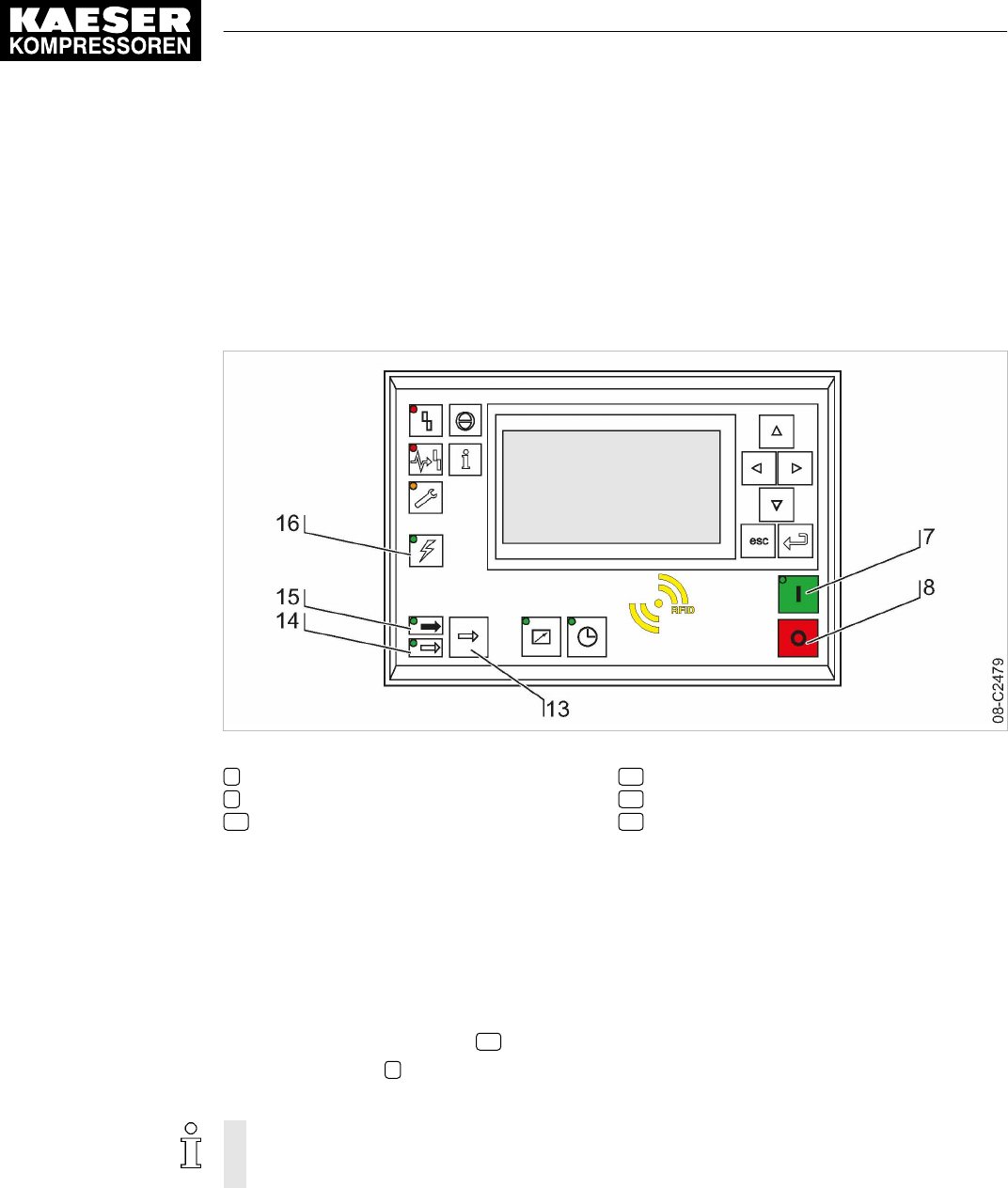
9 Operation
9.1 Switching on and off
Always switch the machine on with the «ON» key and off with the «OFF» key.
Precondition A power supply disconnecting device has been installed by the user.
Fig. 39 Switching on and off
7«ON» key
8«OFF» key
13 «Load/Idle» toggle key
14
IDLE
LED
15
LOAD
LED
16
Controller voltage
LED
9.1.1 Switching on
Precondition No personnel are working on the machine.
All access doors and panels are closed and secure.
1. Switch on the power supply disconnecting device.
2. Switch on the machine and wait for SIGMA CONTROL 2 to start.
The
Controller voltage
LED 16 lights green.
3. Press the «On» 7 key.
The
On
LED lights green.
If a power failure occurs, the machine is not prevented from restarting automatically when
power is resumed.
It can restart automatically as soon as power is restored (see chapter 8.5).
Result The compressor motor starts as soon as system pressure is lower than the setpoint pressure (cut‐
off pressure).
9 Operation
9.1 Switching on and off
158 User Manual Controller
SIGMA CONTROL 2 SCREW FLUID ≥4.0.X No.: 9_9450 07 USE
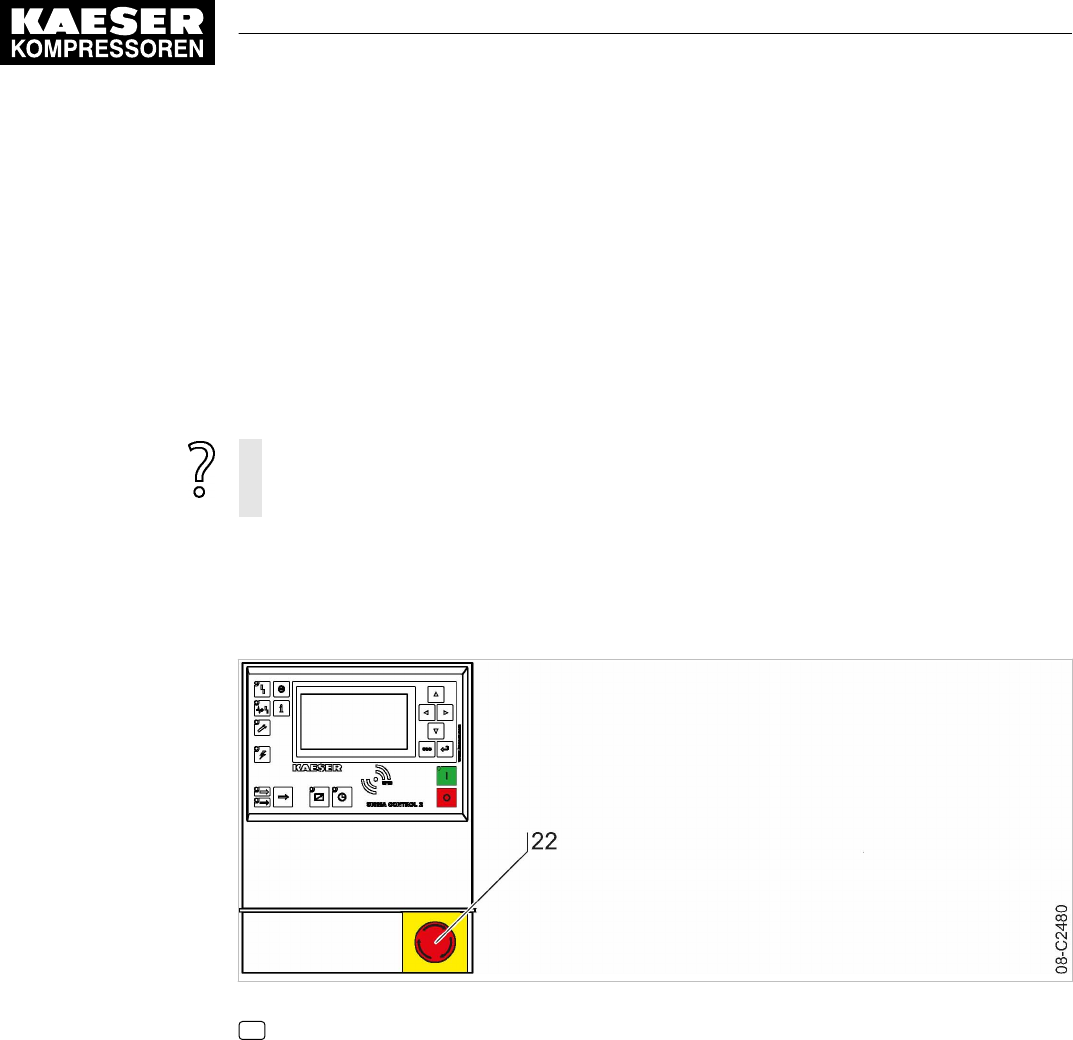
9.1.2 Switching off
1. Press the «OFF» key.
The machine switches to IDLE and the
IDLE
LED flashes. The SIGMA CONTROL 2 dis‐
plays
Stopping
. The
ON
LED extinguishes as soon as the automatic shut-off action is comple‐
ted.
2. Switch off and lock out the power supply disconnecting device.
Result The
Controller voltage
LED extinguishes. The machine is switched off and disconnected from the
power supply.
In rare cases, if you need to shut the machine down immediately and cannot wait until the
automatic shutdown process is finished:
➤ Press «OFF» once again.
9.2 Switching off in an emergency and switching on again
The EMERGENCY STOP push button is located below the control panel.
Fig. 40 Switching off in an emergency
22 EMERGENCY STOP push button
Switching off
➤ Press the EMERGENCY STOP push button.
Result The EMERGENCY STOP push button remains latched after actuation.
The compressor's pressure system is vented and the machine is prevented from automatically re‐
starting.
Switching on
Precondition The fault has been rectified
1. Turn the EMERGENCY STOP push button in the direction of the arrow to unlatch it.
2. Acknowledge any existing alarm messages.
Result The machine can now be started again.
9 Operation
9.2 Switching off in an emergency and switching on again
No.: 9_9450 07 USE
User Manual Controller
SIGMA CONTROL 2 SCREW FLUID ≥4.0.X 159
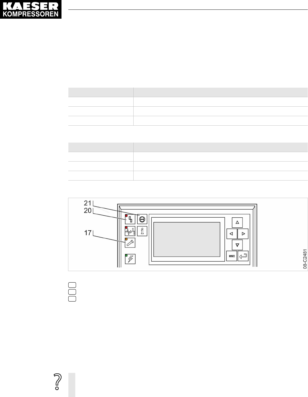
9.3 Acknowledging alarm and warning messages
Messages are displayed on the "new value" principle: You can acknowledge warning or fault mes‐
sages immediately after
Message coming
or
Message going
. However, warning and fault messag‐
es can be acknowledged only following a successful elimination of the corresponding fault.
Message sequence 1 Indication
Message coming LED flashes
Message acknowledged LED illuminates
Message going LED off
Tab. 79 Message sequence 1
Message sequence 2 Indication
Message coming LED flashes
Message going LED flashes
Message acknowledged LED off
Tab. 80 Message sequence 2
Fig. 41 Acknowledging messages
17
Warning
LED (yellow)
20
Alarm
LED (red)
21 Key «Acknowledge»
Alarm message
An alarm message shuts the machine down automatically.
The red
Alarm
LED flashes.
Precondition The fault has been rectified
➤ Press «Ack» to acknowledge the fault message.
Alarm
LED extinguishes. The machine is again ready for operation.
If the machine has been stopped with the EMERGENCY STOP push button.
➤ First turn the EMERGENCY STOP push button in the direction of the arrow to unlatch it.
➤ Then acknowledge the alarm message.
Further information A list of possible alarm messages occurring during operation are shown in chapter 10.2.
9 Operation
9.3 Acknowledging alarm and warning messages
160 User Manual Controller
SIGMA CONTROL 2 SCREW FLUID ≥4.0.X No.: 9_9450 07 USE

Warning message
If maintenance work is to be carried out or if the warning is displayed before an alarm, the yel‐
low
warning
LED flashes.
Precondition The danger of an alarm is eliminated.
Maintenance has been carried out
➤ Press «Ack» to acknowledge the warning message.
The
Maintenance
LED extinguishes. The machine is again ready for operation.
Further information A list of possible warning messages occurring during operation are shown in chapter 10.3.
9.4 Displaying messages
The following information can be accessed in the 1.1
<Status – Messages>
menu:
■ Current messages
─ Last alarm
─ Last warning
─ Number of currently registered alarms and/or warnings
■ Message history: The last 1000 events, these include alarm and warning messages
─ Compressor messages
─ Diagnostic messages
─ System messages
■ Address error: Display of incorrect parameterization in menu X
The information (message) is shown in three lines of the display.
Line Submenu/Segment/Text
1 Selected submenu:
■ Compressor messages
■ Diagnostic messages
■ System messages
2 Segment:
■ Message number
■ Message type
■ Message status
■ Message date
■ Message time
3 Text:
■ Message text
■ –
Tab. 81 Information of a message
Message type and status are shown abbreviated.
Segment Indication Meaning
Message number
0059
(example) Message 0059
9 Operation
9.4 Displaying messages
No.: 9_9450 07 USE
User Manual Controller
SIGMA CONTROL 2 SCREW FLUID ≥4.0.X 161

Segment Indication Meaning
Message type
W
Warning/service message
A
Alarm message
Message status
c
Message has come
g
Message gone
a
Message acknowledged (reset)
Date
04/13/16
(example) Date
Time
08:15:37AM
(example) Time
Tab. 82 Message abbreviations
9.4.1 Selecting the status menu
1. Open the 1.1
<Status – Messages>
menu.
The
Messages
menu is displayed
The number of current alarms and warnings is displayed in the two bottom lines.
88psi 08:15AM 176° F
1.1 Messages Menu
▶1 Current messages Active line
▶2 Message history
Status report 01:00 ☐
__________________________________
current Alarms 2 Number of currently registered alarms
Warnings 0 Number of currently registered warnings
Displaying the last alarm or warning
1. Open the 1.1.1
<Status – Messages – Current messages>
menu.
The third line displays the last alarm or warning message.
88psi 08:15AM 176° F
1.1.1 Current messages Menu
0300 W c 04/16/16 01:32:49PM Last message
SD card write error
0015 W a 04/16/16 01:06:43PM Second to last message
Com-Module communication error
0034 O c 04/13/16 08:15:37AM
E-mail send unsuccessful!
2. Press «Esc» repeatedly to leave this menu.
9 Operation
9.4 Displaying messages
162 User Manual Controller
SIGMA CONTROL 2 SCREW FLUID ≥4.0.X No.: 9_9450 07 USE

Displaying the message history
1. Select the 1.1.2
<Status – Messages – Message history>
menu.
The
Message history
menu is displayed.
88psi 08:15AM 176° F
1.1.2 Message history Menu
▶1 Compressor messages Active line with submenu: Compressor messages
▶2 Diagnostic messages Diagnostic messages
▶3 System messages System messages
2. Press «Enter».
The 1.1.2.1
Compressor messages
menu is displayed.
The third line displays the last alarm or warning message.
88psi 08:15AM 176° F
1.1.2.1 Compressor messages Menu
0300 W c 04/16/16 01:32:49PM Last message
SD card write error Message text for message 0300
0015 W a 04/16/16 01:06:43PM
Com-Module communication error Message text for message 0015
0034 O c 04/13/16 08:15:37AM
E-mail send unsuccessful! Message text for message 0034
3. Press «Esc» repeatedly to leave this menu.
9.5 Displaying the current operating mode
The operating mode is displayed in 2 segments (example):
On/off switching via Load control via
Key
pA
Tab. 83 Operating mode display
9 Operation
9.5 Displaying the current operating mode
No.: 9_9450 07 USE
User Manual Controller
SIGMA CONTROL 2 SCREW FLUID ≥4.0.X 163

1. Select the 1.4
<Status – Current operating mode>
menu.
The
Current operating mode
menu is displayed.
88psi 08:15AM 176° F
1.4 Current operating mode Menu
Compressor on Active line
Key
Load control
pA
·········
Control mode
Abbreviation of operating modes
Segment Indication Meaning
On/off switching via Key «ON» key on the control panel of SIGMA CONTROL 2
Key + clock Cycle Control
Key + remote
contact
Remote contact (external LOAD signal)
Key + remote bus Remote bus (external bus signal)
LOAD control via pA System setpoint pressure
pA
pB System setpoint pressure
pB
pA/pB Clock System setpoint pressure via time control
pA/pB Cycle System setpoint pressure via timer
pA/pB SC2 System setpoint pressure via 2 machines working in mas‐
ter-slave mode
pA/pB RC System setpoint pressure via remote contact
pA/pB RB System setpoint pressure via remote bus
Load RC LOAD remote contact (external LOAD signal)
Load RB Remote bus (external bus signal)
loc.-load RC Local/LOAD remote contact
Tab. 84 Abbreviation of operating modes
9.6 Adjusting the working pressure
➤ Adjust the pressure parameter to suit the compressor and application.
Further information A detailed explanation of all pressure parameter settings is given in chapter 8.4.
9.7 Displaying analog data
The
Performance data
menu provides the following information:
■ Compressor
9 Operation
9.6 Adjusting the working pressure
164 User Manual Controller
SIGMA CONTROL 2 SCREW FLUID ≥4.0.X No.: 9_9450 07 USE

■ Compressor motor
■ Fan
■ Analogue values
■ SIGMA CONTROL 2
Displaying analog data
Precondition Password access level 2 is activated.
The operating mode is displayed.
1. Open the 2
Performance data
menu.
A list of the components is displayed.
88psi 08:15AM 176° F
2 Performance data Menu
▶1 Compressor Active line
▶2 Compressor motor
▶3 Fan
▶4 Analogue values
▶5 SIGMA CONTROL 2
2. If necessary, repeatedly press «Up» or «Down» to select the required component.
3. Press «Enter» access compressor measurement data.
The system displays the measurement data for the compressor.
88psi 08:15AM 176° F
2.1 Compressor Menu
System pressure pNloc 88.0 psi Local System pressure pNloc
·········
ADT T 176°F Airend discharge temperature
dT/dt 0.0°F/s Rise of airend discharge temperature
·········
Oil separator Δp 0.0psi Differential pressure, oil separator cartridge
9.8 Displaying operating data
The following information can be called up in the
Operating data
menu:
■ Operating hours
─ Compressor: Total machine running time
─ On load: Machine running time in LOAD mode
─ Motor: Motor running time (can be changed)
─ Compressor block: Airend running time (can be changed)
─ SIGMA CONTROL 2: Controller running time
9 Operation
9.8 Displaying operating data
No.: 9_9450 07 USE
User Manual Controller
SIGMA CONTROL 2 SCREW FLUID ≥4.0.X 165

■ Switching cycles
─ Load valve on
─ Mains contactor on (adjustable)
■ kWh counter
➤ Reset the run times after replacing the airend or the compressor motor.
➤ Reset the main contactor switching cycle counter after replacing the main contactor.
9.8.1 Checking the operating hours
Displaying the operating hours
Precondition Password access level 2 is activated.
1. Open the 3
Operating data
menu.
88psi 08:15AM 176° F
3 Operating data Menu
▶1 Operating hours Active line
▶2 Switching cycles
▶3 kWh counter
Changing the operating hours
The running times of the compressor motor and airend can be adjusted. This may be required after
a replacement, for example.
Precondition Password access level 2 is activated.
1. Open the 3.1
<Operating data – Operating hours>
menu.
88psi 08:15AM 176° F
3.1 Operating hours Menu
Compressor 3050 h Active line
On load 3030 h
Motor 3050 h
Compressor block 3050 h
SIGMA CONTROL 2 3050 h
2. Use «Up» or «Down» to select the
Compressor block
line.
9 Operation
9.8 Displaying operating data
166 User Manual Controller
SIGMA CONTROL 2 SCREW FLUID ≥4.0.X No.: 9_9450 07 USE

3. Press «Enter».
The display of the running time flashes.
88psi 08:15AM 176° F
3.1 Operating hours Menu
Compressor 3050 h
On load 3030 h
Motor 3050 h
Compressor block 0 h Active line
SIGMA CONTROL 2 3050 h
4. Use «Down» or «Up» key to set the value for operating hours to zero.
5. Press «Enter».
The setting is applied.
6. Press «Esc» repeatedly to leave this menu.
Result The operating hours for the new airend are set to
0 h
.
9.8.2 Checking the switching cycles
The system monitors the usage times of safety-relevant components to ensure the proper
condition of all safety-relevant functions. Depending on the component, the usage time may
be defined by run time or switching cycles. For the main contactor, the usage time is defined
by the maximum permissible number of switching cycles.
The main contactor switching cycle counter in SIGMA CONTROL 2 records the number of
switching cycles and generates a warning message when the maximum permissible number
of switching cycles is exceeded.
When this warning message is generated, the safety-relevant function is no longer ensured.
The main contactor must be replaced!
➤ Comply with all instructions.
Displaying the switching cycles
Precondition Password access level 2 is activated.
1. Select the 3.2
<Operating data – Switching cycles>
menu.
2. Compare the maximum permissible number of switching cycles with the value displayed by the
switching cycle counter.
88psi 08:15AM 176° F
3.2 Switching cycles Menu
Load valve on 3 Active line
·········
Mains contactor on
max: 1100000 ¦ 10227 Maximum value/switching cycle timer
Reset: ☐
Result The safety-relevant function is ensured.
9 Operation
9.8 Displaying operating data
No.: 9_9450 07 USE
User Manual Controller
SIGMA CONTROL 2 SCREW FLUID ≥4.0.X 167

The maximum permissible number of switching cycles have not exceeded.
The main contactor can still be used.
The safety-relevant function is not ensured.
The maximum permissible number of switching cycles have exceeded.
➤ Have the main contactor replaced.
Replacing the main contactor
If the displayed value of the main contactor exceeds the maximum permissible number of
switching cycles, SIGMA CONTROL 2 generates the warning message
0024 Mains contactor
operations ⇞
.
The main contactor must be replaced.
➤ Have the main contactor replaced by an authorized KAESER service representative.
Resetting the main contactor switching cycle counter
➤ Have the main contactor replaced by an authorized KAESER service representative.
9.9 Displaying the frequency converter settings
Precondition The machine is fitted with the frequency converter option (example).
The operating mode is displayed.
1. Select the 10.1.1
<Components – Compressor motor – Power switching>
menu.
2. Use «Up» or «Down» to select the
Local operating mode:
line.
In the two lines underneath
Local operating mode:
, the source for the speed setting and the
setting values for the minimal and maximum speed are shown.
88psi 08:15AM 176° F
10.1.1 Power switching
▶4 SFC USS
▶5 Softstart
▶6 Customer-provided
Local operating mode:
Speed sensor All Speed setting
nMin = 0/min ¦ nMax = 0/min
3. Press «Escape» repeatedly to return to the main menu.
9.10 Setting the maintenance interval
Maintenance tasks are tasks to be completed to ensure the functionality of a technical instal‐
lation.
Time interval established by the manufacturer at which end a maintenance task must be
completed.
Example: Changing the oil change service interval.
9 Operation
9.9 Displaying the frequency converter settings
168 User Manual Controller
SIGMA CONTROL 2 SCREW FLUID ≥4.0.X No.: 9_9450 07 USE
Precondition Password access level 2 is activated.
The operating mode is displayed.
Unauthorized extended maintenance intervals
Progressing damage to the machine up to functional incapacity.
➤ Observe the maintenance intervals of the manufacturer.
Selecting menu maintenance
1. Open the 4
Maintenance
menu.
2. Use «Up» or «Down» to select the
Oil change
line.
88psi 08:15AM 176° F
4 Maintenance
Oil change Active line, Description maintenance interval
3000 h ¦ 0150 h Reset: ☐ Preset interval 3000 h
·········
Air filter
3000 h ¦ 0150 h Reset: ☐
·········
3. Press the «DOWN» key.
The maintenance interval for oil change is displayed as active line.
88psi 08:15AM 176° F
4 Maintenance
Oil change Maintenance interval description
4000 h ¦ 0150 h Reset: ☐ Active line, factory-defined interval
·········
Air filter
3000 h ¦ 0150 h Reset: ☐
·········
4. Press «Enter».
The setting mode is active.
5. Use «Up» or «Down» to set the value for new value for the maintenance interval.
Keep the «Up» key pressed to change the maintenance interval in increments of 10, 100 or
1000.
6. Press «Enter».
The setting is applied.
7. Press «Escape» repeatedly to return to the main menu.
9 Operation
9.10 Setting the maintenance interval
No.: 9_9450 07 USE
User Manual Controller
SIGMA CONTROL 2 SCREW FLUID ≥4.0.X 169
9.11 Checking the safety relief valve
Overview
■ Preparing the inspection
■ Performing the inspection
■ Correct conclusion of the test
■ Resetting
When the check mode is activated, monitoring of internal pressure (blow-off protection - if
provided) and regulation of network pressure are deactivated.
The measured value of the
pi
pressure value is used to describe the following check:
Check box Status
☑ activated
☐ deactivated
Tab. 85 Check box status
Danger of injury from pressurized components!
➤ Perform the following actions in the sequence provided.
Preparing the test
1. Note the activating pressure of the safety relief valve from the machine's nameplate.
2. Press the «OFF» key to shut down the machine.
3. Close the user's shut-off valve between the machine and the pressure system.
4. Log on with password access level 2.
5. Open the 9.1
<Machine test – TÜV inspection>
menu.
88psi 08:15AM 176° F
9.1 TÜV inspection Menu
Safety valve: ☐ Active line with check box
pRV: 232psi ¦ pi ⇞ 0.0psi Safety relief valve activating pressure (example)
Reset : ☐
·········
ADT ⇞ : ☐
Offset 32°F ¦ ADT ⇞ 32.0°F
Performing the test successfully
1. Use «Up» or «Down» to select the
Safety valve:
line.
2. Press «Enter».
The check box
Safety valve:
will flash.
3. Press «Up» key.
The check box is activated.
9 Operation
9.11 Checking the safety relief valve
170 User Manual Controller
SIGMA CONTROL 2 SCREW FLUID ≥4.0.X No.: 9_9450 07 USE

4. Press «Enter».
The test mode is now activated.
88psi 08:15AM 176° F
9.1 TÜV inspection Menu
Safety valve: ☑ Active line with check box
pRV: 232psi ¦ pi ⇞ 36.0psi Safety relief valve activating pressure
Reset : ☐
·········
ADT ⇞ : ☐
Offset 32°F ¦ ADT ⇞ 32.0°F
5.
Risk of hearing damage when safety relief valve blows off!
➤ Close all access doors, replace and secure all removable panels.
➤ Always wear ear protection.
6.
Risk of burns due to released cooling oil and compressed air when blowing off
the safety relief valve!
➤ Close all access doors, replace and secure all removable panels.
➤ Wear eye protection.
7. Press the «ON» key. After the motor start is completed, keep the «LOAD/IDLE» key pressed.
Otherwise, the machine remains in IDLE and is stopped after two minutes.
The machine switches to LOAD and the machine's
pi
pressure rises.
8. Monitor on the display the
pi
pressure rise during the TÜV check.
9. If the
pi
pressure increases to 10 % above the set pressure of the safety relief valve, immedi‐
ately release the «LOAD/IDLE» key.
10. Shut down the machine with the «OFF» key and immediately replace the safety relief valve.
If the alarm message
pRV ⇞
appears, the safety relief valve is defective.
pi
pressure has ex‐
ceeded the set pressure of the safety relief valve by 29.0 psi.
➤ Have the safety relief valve replaced.
Avoid oil mist:
➤ Release the «LOAD/IDLE» key immediately when the safety relief valve responds, in or‐
der to prevent unnecessary oil mist.
Correct conclusion of the test
1. Press «Enter» to switch into setting mode.
The check box
Safety valve:
in the active line flashes.
2. Press the «DOWN» key to deactivate the box.
The check box is deactivated.
3. Press «Enter».
The test mode is deactivated and the test is completed.
4. Press «Escape» repeatedly to return to the main menu.
5. Open the user's shut-off valve between the machine and the air distribution network.
Result The machine is ready for operation.
9 Operation
9.11 Checking the safety relief valve
No.: 9_9450 07 USE
User Manual Controller
SIGMA CONTROL 2 SCREW FLUID ≥4.0.X 171

Resetting
If the test is cancelled when opening the safety relief valve, SIGMA CONTROL 2 will indicate the
highest measured value as internal pressure.
To reset the saved value, activate the
Reset
check box.
➤ Activate the
Reset
check box.
9.12 Checking the temperature sensor and overheating shutdown func‐
tion
The machine should shut down if the airend discharge temperature (ADT) reaches a maximum of
230°F.
SIGMA CONTROL 2 will simulate a higher temperature for checking this function.
For this purpose, SIGMA CONTROL 2 automatically determines an offset value to be displayed.
During the test mode, this offset is added to the actual compressor discharge temperature to cause
the machine to shut down prematurely.
No warning message is generated. However, the corresponding fault message "0015Airend
discharge temperature ADT ⇞" switches off the machine once the maximum discharge tempera‐
ture has been reached.
Overview
■ Allow the machine to warm up, then shut it down and allow it to cool down slightly
■ Performing the test
■ Correct conclusion of the test
■ Resetting
Performing the test
The offset value of
95°F
displayed in activated test mode refers to the example discharge
temperature of
163°F
as shown in the header of the display.
Precondition Allow the machine to warm up. Shut down the machine as soon as the discharge temperature has
stabilized.
Machine has cooled down by approximately 41°F (from discharge temperature of warmed up ma‐
chine).
Password access level 2 is activated.
1. Open the 9.1
<Machine test – TÜV inspection>
menu.
2. Use the «Up» or «Down» keys to select the
ADT
line.
88psi 08:15AM 176° F
9.1 TÜV inspection Menu
Safety valve: ☐
pRV: 232psi ¦ pi ⇞ 0.0psi Safety relief valve activating pressure (example)
Reset : ☐
·········
ADT ⇞ : ☐ Active line with check box
Offset 32°F ¦ ADT ⇞ 32.0°F
9 Operation
9.12 Checking the temperature sensor and overheating shutdown function
172 User Manual Controller
SIGMA CONTROL 2 SCREW FLUID ≥4.0.X No.: 9_9450 07 USE

3. Press «Enter».
The
ADT ⇞
check box flashes.
4. Press «Up» key.
The check box is activated.
5. Press «Enter».
The
Offset
display changes to
95°F
.
The
ADT ⇞
display changes to
226°F
.
The test mode is now activated.
88psi 08:15AM 16 3° F
9.1 TÜV inspection Menu
Safety valve: ☐
pRV: 232psi ¦ pi ⇞ 0.0psi Safety relief valve activating pressure (example)
Reset : ☐
·········
ADT ⇞ : ☑ Active line with check box
Offset 95°F ¦ ADT ⇞ 226°F
6. Press the «ON» key.
The machine is running in LOAD.
The discharge temperature increases again.
The machine will switch off as soon as the discharge temperature attains a value of
230°F
.
The machine does not shut down?
➤ Abort the test and contact an authorized KAESER service representative soon as possi‐
ble.
Correct conclusion of the test
1. Press «Enter» to switch into setting mode.
The setting mode is active.
The check box flashes in line
ADT ⇞
.
2. Press the «DOWN» key.
The check box is deactivated.
3. Press «Enter» to accept the setting.
The offset is reset to
32°F
.
Result The test mode is deactivated and the test is completed.
Resetting
SIGMA CONTROL 2 will display the highest measured value if the test for switching off at high
temperature is aborted.
Activate the
Reset
check box in order to reset the stored value.
➤ Activate the
Reset
check box.
9 Operation
9.12 Checking the temperature sensor and overheating shutdown function
No.: 9_9450 07 USE
User Manual Controller
SIGMA CONTROL 2 SCREW FLUID ≥4.0.X 173

9.13 Save data
SIGMA CONTROL 2 settings can be backed up to an SD card.
Precondition An SD card with compatible file system (FAT32) and minimum 50 MB free memory is plugged into
the SD card slot X5 of SIGMA CONTROL 2
The write protection of the SD card has been deactivated.
Password access level 2 is activated.
1. Open the 5.10
<Configuration – Save data>
menu.
2. Use «Up» or «Down» to select the
Language:
line.
88psi 08:15AM 176° F Header
5.10 Save data Menu
Language: en_US English Active line
·········
Save data : ☐
3. Press «Enter» to switch into setting mode.
The display for the set language flashes.
4. Use «Up» or «Down» to select the desired language.
5. Press «Enter» to accept the setting.
The setting is applied.
6. Use «Up» or «Down» to select the
Save data
line.
88psi 08:15AM 176° F Header
5.10 Save data Menu
Language: en_US English
·········
Save data : ☑ Active line
7. Press «Enter».
The check box
Save data
will flash.
8. Press «Up» key.
The check box is activated.
9. Press «Enter».
A security query is displayed.
10. Press «Enter».
Result The settings are saved on the SD card.
9 Operation
9.13 Save data
174 User Manual Controller
SIGMA CONTROL 2 SCREW FLUID ≥4.0.X No.: 9_9450 07 USE

10 Fault Recognition and Rectification
10.1 Basic instructions
The following tables are intended to assist in locating faults.
SIGMA CONTROL 2 will indicate three types of faults:
■ Fault on the machine:
The
red LED
flashes, the machine is shut down, see chapters 10.2 and 10.5.
■ Fault on the controller:
The machine is shut down, see chapter 10.6.
■ Warning:
The
yellow LED
illuminates, the machine is not shut down, see chapter 10.3.
The messages valid for your machine are dependent on the controller and individual equipment.
1. Do not attempt fault rectification measures other than those given in this manual!
2. In all other cases:
Have the fault rectified by an authorized KAESER service representative.
10.2 Interpreting alarm messages
If an input signal is classified as an alarm, the controller will display the fault upon the signal's
arrival.
Consequences:
■ The
red LED
flashes:
■ The controller switches the machine off.
Alarm messages are identified with the letter A.
The message numbers are not numbered consecutively.
Meanings of designation of fault messaged within this table with "%d".
1) Messages 0073–0078 and 0081–0096 are customer-specific and may differ from the suggested
values.
Complete them with your defined message text, possible causes and remedies. (see chapter 8.11).
Message Possible cause Remedy
0001 A
Direction of rotation
The compressor drive motor is
turning in the wrong direction.
Changeover phase lines L1 and L2.
0002 A
Motor temperature ⇞
Compressor drive motor overhea‐
ted.
Keep ambient conditions within
specified limits.
Check the cooling air supply.
Clean the motor.
0003 A
pRV ⇞
The activating pressure of the
safety relief valve on the oil sepa‐
rator tank has been exceeded.
Change the safety relief valve.
0004 A
EMERGENCY STOP
EMERGENCY STOP push button
actuated.
Unlatch the push button.
10 Fault Recognition and Rectification
10.1 Basic instructions
No.: 9_9450 07 USE
User Manual Controller
SIGMA CONTROL 2 SCREW FLUID ≥4.0.X 175

Message Possible cause Remedy
0005 A
Oil separator
Temperature ⇞
Maximum air temperature at the
oil separator tank outlet is excee‐
ded.
Check the line to the trip relay.
Check the oil separator cartridge
for damage.
0007 A
Power supply monitor
Fault in main power supply. Have the main power supply
checked.
0008 A
Diagnostics group alarm
A diagnostic message has occur‐
red.
For more details, see the text of the
diagnostic message.
0010 A
Blow-off protection ⇞
The activating pressure of the
safety relief valve on the oil sepa‐
rator tank has been exceeded.
Change the oil separator cartridge.
Open the shut-off valve in the vent‐
ing line.
0011 A
Oil-/air cooler fan
Overcurrent
Overload shutdown of the fan mo‐
tor.
Investigate cause of shutdown.
Reset the overload protection relay.
0012 A
Access doors
Door open / interlocked panel re‐
moved while the machine is run‐
ning.
Fit and secure all panels and close
access doors.
0013 A
Compressor motor
overcurrent
Overload shutdown of the com‐
pressor drive motor.
Investigate cause of shutdown.
Change the oil separator cartridge.
0014 A
Oil cooler fan overcurrent
Overload shutdown of the oil
cooler fan motor.
Investigate cause of shutdown.
Reset the overload protection relay.
0015 A
Airend discharge
temperature ADT ⇞
Maximum permissible airend dis‐
charge temperature (ADT) excee‐
ded.
Keep ambient conditions within
specified limits.
Clean the cooler.
Check the cooling oil level.
0016 A
Air cooler - Fan
Overcurrent
Overload shutdown of the air
cooler fan motor.
Investigate cause of shutdown.
Reset the overload protection relay.
0017 A
Safety shutdown ADT
Maximum permissible airend dis‐
charge temperature (ADT) excee‐
ded.
Keep ambient conditions within
specified limits.
Clean the cooler.
Check the cooling oil level.
0018 A
Interior fan Overcurrent
Overload shutdown of the air
cooler fan motor.
Investigate cause of shutdown.
Reset the overload protection relay.
0019 A
Internal pressure pi ⇟
Inlet valve defective. Contact an authorized KAESER
service representative.
0021 A
Refrigeration dryer T ⇟
Refrigerated dryer:
Compressed air temperature too
low.
Contact an authorized KAESER
service representative.
0022 A
Oil separator Δp ⇞
Oil separator cartridge clogged. Change the oil separator cartridge.
0033 A
Oil pressure ⇟
Oil level too low.
Defective oil pump (provided only
in vacuum machines).
Check the cooling oil level.
If necessary, request that an au‐
thorized KAESER service repre‐
sentative replaces the oil pump.
10 Fault Recognition and Rectification
10.2 Interpreting alarm messages
176 User Manual Controller
SIGMA CONTROL 2 SCREW FLUID ≥4.0.X No.: 9_9450 07 USE

Message Possible cause Remedy
0034 A
Mains contactor on?
Main contactor of the compressor
motor does not open.
Check main contactor and wiring.
0035 A
Cabinet fan I ⇞
Overload shutdown of the control
cabinet fan motor.
Contact an authorized KAESER
service representative.
0038 A
PD temperature ⇟
Package discharge (PD) temper‐
ature too low.
Contact an authorized KAESER
service representative.
0039 A
PD temperature ⇞
Package discharge (PD) temper‐
ature too high.
Check the cooling oil level.
Clean the cooler.
Check the fan motor.
0040 A
Mains contactor off?
Main contactor of the compressor
motor does not deactivate.
Check main contactor and wiring.
0041 A
Mains voltage ⇟
Second power failure. Check power supply voltage.
Checking the door interlock switch.
0042 A
Back pressure stop
Back pressure in the oil separator
tank caused by defective venting.
Check venting line.
0043 A
Airend discharge
temperature ADT rise
dT/dt⇞
The rate of rise of the airend dis‐
charge temperature (ADT) is too
fast.
Check the cooling oil level.
0044 A
No pressure buildup
The machine does not produce
compressed air.
The working pressure does not
rise above 50 psi within the speci‐
fied time period.
The machine does not enter
LOAD mode.
Minimum pressure check valve
defective.
Check the machine for leaks.
Check coupling and V-belt.
Contact an authorized KAESER
service representative.
0048 A
High-voltage cell
Fault in the high voltage cell. Contact an authorized KAESER
service representative.
0050 A
Customer-provided power
element
Power switching module not
ready or defective.
Check power switching module.
0051 A
Aggregate A
Aggregate A failed. Contact an authorized KAESER
service representative.
0052 A
Aggregate B
Aggregate B failed. Contact an authorized KAESER
service representative.
0056 A
RD condensate drain
Refrigerated dryer:
Condensate drain defective.
Refrigerated dryer:
Check the condensate drain and
conduits.
0057 A
Model?
Compressor model uncertain. Contact an authorized KAESER
service representative.
0058 A
Condensate drain
Condensate drain defective. Check the condensate drain and
conduits.
10 Fault Recognition and Rectification
10.2 Interpreting alarm messages
No.: 9_9450 07 USE
User Manual Controller
SIGMA CONTROL 2 SCREW FLUID ≥4.0.X 177

Message Possible cause Remedy
0059 A
Back pressure run
Drive belt or coupling broken. Drive belts:
Replace drive belt.
Coupling:
Contact an authorized KAESER
service representative.
0060 A
Softstart
Fault in the soft start equipment. Contact an authorized KAESER
service representative.
0062 A
Refrigeration dryer p ⇞
Refrigerated dryer:
Pressure too high in refrigerant
circuit.
Safety pressure switch tripped.
Clean the refrigerant condenser.
Check the fan motor.
Maintain operating conditions.
0063 A
Refrigeration dryer p ⇟
Refrigerated dryer:
Refrigerant lost; pressure in the
refrigerant circuit too low.
Inlet pressure switched tripped.
Contact an authorized KAESER
service representative.
0064 A
Refrigeration dryer
compressor motor
temperature ⇞
Permissible ambient tempera‐
tures exceeded.
Condenser cooling insufficient.
Compressed air inlet temperature
is too high.
Low refrigerant level.
Check and lower ambient tempera‐
tures.
Clean the condenser.
Check the fan.
Check compressed air cooling at
the compressor.
Clean the compressor cooler.
Contact an authorized KAESER
service representative.
0067 A
SC2 <=> SC2
communication error
The electrical connection is inter‐
rupted.
IP configuration incorrect.
Check the electrical connection.
Check the IP configuration.
0073 A
External message 1
1)
0074 A
External message 2
1)
0075 A
External message 3
1)
0076 A
External message 4
1)
0077 A
External message 5
1)
0078 A
External message 6
1)
0081 A
AnMod_p_1
1)
0082 A
AnMod_p_2
1)
0083 A
AnMod_p_3
1)
10 Fault Recognition and Rectification
10.2 Interpreting alarm messages
178 User Manual Controller
SIGMA CONTROL 2 SCREW FLUID ≥4.0.X No.: 9_9450 07 USE

Message Possible cause Remedy
0084 A
AnMod_p_4
1)
0085 A
AnMod_T_1
1)
0086 A
AnMod_T_2
1)
0087 A
AnMod_T_3
1)
0088A
AnMod_T_4
1)
0089A
AnMod_I_1
1)
0090 A
AnMod_I_2
1)
0092 A
T-Switch inlet
temperature
1)
0093 A
p-Switch pi
1)
0094 A
T-Switch ADT
1)
0095 A
p-Switch pN
1)
0096 A
T-Switch PDT
1)
0100 A
Star contactor on?
Star contactor of the compressor
motor does not activate.
Check star contactor and wiring.
0101 A
Star contactor off?
Star contactor of the compressor
motor does not deactivate.
Check star contactor and wiring.
0102 A
Delta contactor on?
Delta contactor of the compressor
motor does not activate.
Check delta contactor and wiring.
0103 A
Delta contactor off?
Delta contactor of the compressor
motor does not deactivate.
Check delta contactor and wiring.
0104 A
High-voltage cell on?
High-voltage cell does not acti‐
vate.
Contact an authorized KAESER
service representative.
0105 A
High-voltage cell off?
High-voltage cell does not deacti‐
vate.
Contact an authorized KAESER
service representative.
0106 A
Softstarter DI%.2d
closed?
Soft start device does not acti‐
vate.
Contact an authorized KAESER
service representative.
0107 A
Softstarter DI%.2d open?
Soft start device does not deacti‐
vate.
Contact an authorized KAESER
service representative.
0108 A
Softstarter DI%.2d
closed?
Run-up of the soft start device is
not completed.
Contact an authorized KAESER
service representative.
10 Fault Recognition and Rectification
10.2 Interpreting alarm messages
No.: 9_9450 07 USE
User Manual Controller
SIGMA CONTROL 2 SCREW FLUID ≥4.0.X 179

Message Possible cause Remedy
0109 A
Softstarter DI%.2d open?
Run-down of the soft start device
is not completed.
Contact an authorized KAESER
service representative.
0111 A
Oil-/air cooler fan Mains
contactor on?
Main contactor of the fan motor
does not activate.
Check main contactor and wiring.
0112 A
Oil-/air cooler fan Mains
contactor off?
Main contactor of the fan motor
does not deactivate.
Check main contactor and wiring.
0113 A
Oil-/air cooler fan Speed
↓ on?
Main contactor of the fan motor
does not activate.
Check main contactor and wiring.
0114 A
Oil-/air cooler fan Speed
↓ off?
Main contactor of the fan motor
does not deactivate.
Check main contactor and wiring.
0115 A
Oil-/air cooler fan Speed
↑ on?
Main contactor of the fan motor
does not activate.
Check main contactor and wiring.
0116 A
Oil-/air cooler fan Speed
↑ off?
Main contactor of the fan motor
does not deactivate.
Check main contactor and wiring.
0121 A
Oil cooler fan Mains
contactor on?
Main contactor of the fan motor
does not activate.
Check main contactor and wiring.
0122 A
Oil cooler fan Mains
contactor off?
Main contactor of the fan motor
does not deactivate.
Check main contactor and wiring.
0131 A
Air cooler - Fan Mains
contactor on?
Main contactor of the fan motor
does not activate.
Check main contactor and wiring.
0132 A
Air cooler - Fan Mains
contactor off?
Main contactor of the fan motor
does not deactivate.
Check main contactor and wiring.
0141 A
Interior fan Mains
contactor on?
Main contactor of the fan motor
does not activate.
Check main contactor and wiring.
0142 A
Interior fan Mains
contactor off?
Main contactor of the fan motor
does not deactivate.
Check main contactor and wiring.
0150 A
Redundancy contactor
on?
Redundancy contactor does not
activate.
Check redundancy contactor and
wiring.
0151 A
Redundancy contactor
off?
Redundancy contactor does not
deactivate.
Check redundancy contactor and
wiring.
0200 A
Compressor motor USS
alarm
Frequency converter fault. Contact an authorized KAESER
service representative.
10 Fault Recognition and Rectification
10.2 Interpreting alarm messages
180 User Manual Controller
SIGMA CONTROL 2 SCREW FLUID ≥4.0.X No.: 9_9450 07 USE

Message Possible cause Remedy
0201 A
Compressor motor USS
alarm
Frequency converter fault. Contact an authorized KAESER
service representative.
0202 A
Compressor motor USS
alarm
Frequency converter fault. Contact an authorized KAESER
service representative.
0203 A
Compressor motor FC
PKW failure P%d.E%d
Frequency converter fault. Contact an authorized KAESER
service representative.
0204 A
Compressor motor FC
PKW failure P%d.E%d
Frequency converter fault. Contact an authorized KAESER
service representative.
0205 A
Compressor motor FC
PKW failure P%d.E%d
Frequency converter fault. Contact an authorized KAESER
service representative.
0206 A
USS bus communication
error %d
Fault caused by software driver. Contact an authorized Kaeser serv‐
ice representative.
0207 A
USS bus communication
error %d
Fault caused by software driver. Contact an authorized KAESER
service representative.
0208 A
USS bus communication
error %d
Fault caused by software driver. Contact an authorized KAESER
service representative.
0210 A
Compressor motor FC
Over temperature alarm
Compressor motor temperature
too high.
Keep ambient conditions within
specified limits.
Cooler maintenance.
0211 A
Compressor motor FC
Alarm %d
Fault message of the frequency
converter with message number
(here: 50).
Contact an authorized KAESER
service representative.
0212 A
Compressor motor FC
AI2 error
Speed sensor of the frequency
converter (here: AI2).
Contact an authorized KAESER
service representative.
0220 A
Compressor motor FC
Motor overload alarm
Compressor motor overload. Contact an authorized KAESER
service representative.
0221 A
Compressor motor FC
Alarm %d
Fault message of the frequency
converter with message number
(here: 50).
Contact an authorized KAESER
service representative.
0230 A
Compressor motor FC
Motor overload alarm
Compressor motor overload. Contact an authorized KAESER
service representative.
0231 A
Compressor motor FC
Alarm %d
Fault message of the frequency
converter with message number
(here: 50).
Contact an authorized KAESER
service representative.
10 Fault Recognition and Rectification
10.2 Interpreting alarm messages
No.: 9_9450 07 USE
User Manual Controller
SIGMA CONTROL 2 SCREW FLUID ≥4.0.X 181

Message Possible cause Remedy
0232 A
Compressor motor FC
AI1 error
Speed sensor of the frequency
converter (here: AI1).
Contact an authorized KAESER
service representative.
0240 A
Compressor motor USS
alarm
Fault caused by software driver. Contact an authorized KAESER
service representative.
0241 A
Compressor motor FC
PKW failure P%d.E%d
Frequency converter fault. Contact an authorized KAESER
service representative.
0242 A
USS bus communication
error %d
Fault caused by software driver. Contact an authorized KAESER
service representative.
0243 A
Compressor motor FC
Alarm %d
Fault message of the frequency
converter with message number
(here: 50).
Contact an authorized KAESER
service representative.
0244 A
Compressor motor FC
activation failed
Frequency converter incorrectly
activated.
Contact an authorized KAESER
service representative.
0245 A
Compressor motor FC
run-up time exceeded
Minimum speed not reached with
a defined time (can be set).
Check the set value.
Contact an authorized KAESER
service representative.
0246 A
Compressor motor FC
nMin undershot
Below minimum speed by a spe‐
cific speed (can be set) for a spe‐
cific time (can be set).
Check the set value.
Contact an authorized KAESER
service representative.
0247 A
Compressor motor FC:
STO function inactive
Parametrization error. Contact an authorized KAESER
service representative.
0248 A
Compressor motor FC off
- STO?
Parametrization error. Contact an authorized KAESER
service representative.
0251 A
Oil-/air cooler fan USS
alarm
Fault caused by software driver. Contact an authorized KAESER
service representative.
0252 A
Oil-/air cooler fan FC
PKW failure P%d.E%d
Frequency converter fault. Contact an authorized KAESER
service representative.
0253 A
Oil-/air cooler fan FC
PKW failure P%d.E%d
Frequency converter fault. Contact an authorized KAESER
service representative.
0254 A
USS bus communication
error %d
Fault caused by software driver. Contact an authorized KAESER
service representative.
0255 A
USS bus communication
error %d
Fault caused by software driver. Contact an authorized KAESER
service representative.
10 Fault Recognition and Rectification
10.2 Interpreting alarm messages
182 User Manual Controller
SIGMA CONTROL 2 SCREW FLUID ≥4.0.X No.: 9_9450 07 USE

Message Possible cause Remedy
0260 A
Oil-/air cooler fan FC
Motor overload alarm
Fan motor overload. Contact an authorized KAESER
service representative.
0261 A
Oil-/air cooler fan FC
Alarm %d
Fault message of the frequency
converter with message number.
Contact an authorized KAESER
service representative.
0270 A
Oil-/air cooler fan FC
Motor overload alarm
Fan motor overload. Contact an authorized KAESER
service representative.
0271 A
Oil-/air cooler fan FC
Alarm %d
Fault message of the frequency
converter with message number
(here: 50).
Contact an authorized KAESER
service representative.
0280 A
Oil-/air cooler fan USS
alarm
Fault caused by software driver. Contact an authorized KAESER
service representative.
0281 A
Oil-/air cooler fan FC
PKW failure P%d.E%d
Frequency converter fault. Contact an authorized KAESER
service representative.
0282 A
Oil-/air cooler fan USS
error %d
Fault caused by software driver. Contact an authorized KAESER
service representative.
0283 A
Oil-/air cooler fan FC
Alarm %d
Fault message of the frequency
converter with message number
(here: 50).
Contact an authorized KAESER
service representative.
0284 A
Oil-/air cooler fan FC
activation failed
Fan frequency converter incor‐
rectly activated.
Contact an authorized KAESER
service representative.
0287 A
Oil-/air cooler fan FC:
STO function inactive
Frequency converter parametriz‐
ing incorrect.
Check frequency converter para‐
metrizing.
Contact an authorized KAESER
service representative.
0288 A
Oil-/air cooler fan FC off -
STO?
Frequency converter parametriz‐
ing incorrect.
Check frequency converter para‐
metrizing.
Contact an authorized KAESER
service representative.
0301 A
Oil cooler fan USS alarm
Frequency converter fault. Contact an authorized KAESER
service representative.
0303 A
Oil cooler fan FC PKW
failure P%d.E%d
Frequency converter fault. Contact an authorized KAESER
service representative.
0305 A
USS bus communication
error %d
Fault caused by software driver. Contact an authorized KAESER
service representative.
0320 A
Oil cooler fan FC Motor
overload alarm
Fan motor overload. Contact an authorized KAESER
service representative.
10 Fault Recognition and Rectification
10.2 Interpreting alarm messages
No.: 9_9450 07 USE
User Manual Controller
SIGMA CONTROL 2 SCREW FLUID ≥4.0.X 183

Message Possible cause Remedy
0321 A
Oil cooler fan FC
Alarm %d
Fault message of the frequency
converter with message number
(here: 50).
Contact an authorized KAESER
service representative.
0330 A
Oil cooler fan USS alarm
Frequency converter fault. Contact an authorized KAESER
service representative.
0331 A
Oil cooler fan FC PKW
failure P%d.E%d
Frequency converter fault. Contact an authorized KAESER
service representative.
0332 A
USS bus communication
error %d
Fault caused by software driver. Contact an authorized KAESER
service representative.
0333 A
Oil cooler fan FC
Alarm %d
Fault message of the frequency
converter with message number.
Contact an authorized KAESER
service representative.
0334 A
Oil cooler fan FC
activation failed
Fan frequency converter incor‐
rectly activated.
Contact an authorized KAESER
service representative.
0337 A
Oil cooler fan FC: STO
function inactive
Frequency converter parametriz‐
ing incorrect.
Check frequency converter para‐
metrizing.
Contact an authorized KAESER
service representative.
0338 A
Oil cooler fan FC off -
STO?
Frequency converter parametriz‐
ing incorrect.
Check frequency converter para‐
metrizing.
Contact an authorized KAESER
service representative.
0500 A
I/O parameterisation
incorrect in module %d!
An I/O address has been as‐
signed more than once.
Display and correct the incorrect
parameters in the
1.1.3Address
error
menu.
Tab. 86 Fault messages, possible causes and remedies
10.3 Interpreting warning messages
If an input signal is classified as a warning, the controller will display the warning upon the
signal's arrival.
Consequences:
■ The
yellow LED
flashes.
■ The controller does not switch off the machine.
Warning messages are identified with the letter W.
The message numbers are not numbered consecutively.
In this table, you will see "%d" for a variable value, e.g. a number, duration or I/O address.
10 Fault Recognition and Rectification
10.3 Interpreting warning messages
184 User Manual Controller
SIGMA CONTROL 2 SCREW FLUID ≥4.0.X No.: 9_9450 07 USE

1) Messages 0073–0078 and 0081–0096 are customer-specific and may differ from the suggested
values.
Complete them in the table below with your defined message text, possible causes and remedies
(see chapter 8.11).
Message Possible cause Remedy
0001 W
Equipment number
incomplete
Equipment number entered incompletely
or not at all.
Contact an authorized
KAESER service representa‐
tive.
0002 W
Motor temperature ↑
Drive motor overheating. Keep ambient conditions with‐
in specified limits.
Check the cooling air supply.
Clean the motor.
0004 W
Oil separator Δp ↑
Increased differential pressure of the oil
separator cartridge.
Oil separator cartridge clogged.
Change the oil separator car‐
tridge.
0008 W
Airend discharge
temperature ADT ↑
Maximum airend discharge temperature
will soon be reached.
Clean the cooler.
Check the cooling oil level.
Replace the oil filter element.
Ensure adequate ventilation.
Keep surrounding tempera‐
ture within recommended lim‐
its.
0011 W
Oil filter Δp ↑
Increased pressure differential of the oil
filter.
Oil filter clogged.
Change the oil filter.
0013 W
Air filter Δp ↑
Air filter clogged. Change the air filter.
0015 W
Com-Module
communication error
The bus link via PROFIBUS interface is
interrupted.
Check bus lines and plug.
0021 W
Refrigeration dryer T ⇟
Refrigerated dryer:
Compressed air temperature too low.
Keep ambient conditions with‐
in specified limits.
Contact an authorized
KAESER service representa‐
tive.
0024 W
Mains contactor
operations ⇞
The maximum permissible number of
switching cycles has been exceeded.
Have the main contactor re‐
placed by an authorized
KAESER service representa‐
tive.
0025 W
Oil separator h ⇞
Oil separator cartridge:
Maintenance interval has elapsed.
Change the oil separator car‐
tridge.
0026 W
Oil change h ⇞
Cooling oil:
Maintenance interval has elapsed.
Change the cooling oil.
0027 W
Oil filter h ⇞
Oil filter:
Maintenance interval has elapsed.
Change the oil filter.
10 Fault Recognition and Rectification
10.3 Interpreting warning messages
No.: 9_9450 07 USE
User Manual Controller
SIGMA CONTROL 2 SCREW FLUID ≥4.0.X 185

Message Possible cause Remedy
0028 W
Air filter h ⇞
Air filter:
Maintenance interval has elapsed.
Change the air filter.
0029 W
Valve inspection h ⇞
Valves:
Maintenance interval has elapsed.
Contact an authorized
KAESER service representa‐
tive.
0030 W
Belt/coupling inspection
h ⇞
Belt tension/coupling:
Maintenance interval has elapsed.
Carry out a visual inspection.
Tension the drive belt.
0031 W
Motor bearing h ⇞
Motor bearing of compressor motor:
Maintenance interval has elapsed.
Contact an authorized
KAESER service representa‐
tive.
0032 W
Electrical equipment h
⇞
Electric components and electrical instal‐
lation:
Maintenance interval has elapsed.
Inspect and reset the mainte‐
nance interval counter.
0033 W
Fan bearing h ⇞
Motor bearing of fan motors:
Maintenance interval has elapsed.
Contact an authorized
KAESER service representa‐
tive.
0034 W
PD temperature ↓
Package discharge (PD) temperature too
low.
Contact an authorized
KAESER service representa‐
tive.
0035 W
PD temperature ↑
Compressed air discharge temperature
too high.
Clean the cooler.
Check the cooling oil level.
0036 W
Motor starts/h ⇞
The permissible number of motor starts
was exceeded in the last 60 minutes.
Extend the idle period.
Increase the capacity of the
air receiver.
Increase the cross-section of
piping between compressor
and air receiver.
0037 W
Motor starts/d ⇞
The permissible number of motor starts
was exceeded in the last 24 hours.
Extend the idle period.
Increase the capacity of the
air receiver.
Increase the cross-section of
piping between compressor
and air receiver.
0038 W
Blow-off protection ↑
The safety relief valve's activating pres‐
sure will soon be reached.
Change the oil separator car‐
tridge.
Open the shut-off valve in the
venting line.
0041 W
Mains voltage ↓
1. Power failure:
The machine is automatically restarted.
Check power supply.
0043 W
External load signal?
Ambiguous external load signal:
Increased cut-out pressure exceeded.
The external load control has not switch‐
ed to IDLE.
Check settings of the external
controller. Take into account
pressure drops across filters
and dryer.
10 Fault Recognition and Rectification
10.3 Interpreting warning messages
186 User Manual Controller
SIGMA CONTROL 2 SCREW FLUID ≥4.0.X No.: 9_9450 07 USE

Message Possible cause Remedy
0044 W
Oil temperature ↓
Cooling oil temperature too low. Check temperature switch,
line and connection.
Check the oil circuit.
Increase room temperature.
0045 W
DO test active
Test operation for the manual actuation of
individual outputs is active.
Switch the power supply off
and on again.
0046 W
System pressure ↓
System pressure has fallen below the set
system pressure low' value.
Air consumption too high.
Check air demand.
Check cable runs and sensor
connections.
Check the system pressure
low' warning value.
0047 W
No pressure buildup
The machine does not produce com‐
pressed air.
The working pressure does not rise
above 50 psi bar within the pre-set time
period.
The machine does not enter LOAD mode
Minimum pressure check valve defective.
Check the machine for leaks.
Check coupling and V-belt.
Contact an authorized
KAESER service representa‐
tive.
0048 W
Bearing lube h ⇞
Re-grease the motor bearings.
Maintenance interval has elapsed.
Re-grease the motor bear‐
ings.
0049 W
Annual maintenance
Last maintenance was 1 year ago. Carry out the necessary main‐
tenance and reset the corre‐
sponding maintenance inter‐
val counter.
0050 W
Fan bearing lube h ⇞
Maintenance interval has elapsed. Re-grease the fan bearing.
0051 W
Double aggregate
emergency operation!
Last maintenance was 1 year ago. Carry out the necessary main‐
tenance and reset the corre‐
sponding maintenance inter‐
val counter.
0053 W
Condensate drain 2
Condensate drain defective.
Too much condensate.
Line interrupted.
Condensate cannot be drained.
Check the condensate drain
and condensate lines.
Check the lines.
Check EcoDrain.
Check inlet conditions.
0058 W
SC2 <=> SC2
communication error
The electrical connection is interrupted.
IP configuration incorrect
Check the electrical connec‐
tions.
Check the IP configuration.
0059 W
Start temperature ↓↓
The airend temperature is too low (<
−50°F) for the machine to be operated.
Keep ambient conditions with‐
in specified limits.
0060 W
Start temperature ↓
The airend temperature is too low
(<+35°F).
Keep ambient conditions with‐
in specified limits.
0061 W
Compressor T ↓
The airend discharge temperature (ADT)
did not reach the minimum value within
the specified time.
Contact an authorized
KAESER service representa‐
tive.
10 Fault Recognition and Rectification
10.3 Interpreting warning messages
No.: 9_9450 07 USE
User Manual Controller
SIGMA CONTROL 2 SCREW FLUID ≥4.0.X 187

Message Possible cause Remedy
0062 W
Refrigeration dryer p ⇞
Refrigerated dryer:
Pressure too high in the refrigerant circuit.
Safety pressure switch tripped.
Clean the refrigerant con‐
denser.
Check the fan motor.
Maintain operating conditions.
0063 W
Refrigeration dryer p ⇟
Refrigerated dryer:
Refrigerant lost; pressure in the refriger‐
ant circuit too low. Inlet pressure switch
tripped.
Contact an authorized
KAESER service representa‐
tive.
0064 W
Refrigeration dryer
compressor motor
temperature ⇞
Permissible ambient temperatures excee‐
ded.
Condenser cooling insufficient
Compressed air inlet temperature is too
high.
Low refrigerant level.
Check and lower ambient
temperatures.
Clean the condenser.
Check the fan.
Check compressed air cooling
at the compressor.
Clean the compressor cooler.
Contact an authorized
KAESER service representa‐
tive.
0065 W
Refrigeration dryer
external shut-off
Low room temperature.
Risk that refrigerated dryer freezes.
Refrigerated dryer has automatically been
deactivated.
Keep ambient conditions with‐
in specified limits.
Check temperature sensor.
0067 W
System pressure ↑
System pressure is above the "system
pressure high" value.
Check cable runs and sensor
connections.
Check the "system pressure
high" warning setting.
0068 W
Condensate drain
Condensate drain defective.
Too much condensate.
Line interrupted.
Condensate cannot be drained.
Check the condensate drain
and condensate lines.
Check the lines.
Check EcoDrain.
Check inlet conditions.
0069 W
Error operation without
RD → Call service!
Refrigerated dryer defective.
Compressed air supply with non-dried air
is activated.
Immediately contact an au‐
thorized KAESER service rep‐
resentative.
0070 W
Refrigeration dryer T ↑
Refrigerated dryer:
Compressed air temperature too high.
Maintain operating conditions.
Clean the refrigerant con‐
denser.
Clean the cooler.
Install an extractor fan.
0071 W
Oil level ↓
Cooling oil level too low. Top off the cooling oil.
0072 W
RD condensate drain
Refrigerated dryer:
Condensate drain defective.
Check the condensate drain.
0073 W
External message 1
1)
10 Fault Recognition and Rectification
10.3 Interpreting warning messages
188 User Manual Controller
SIGMA CONTROL 2 SCREW FLUID ≥4.0.X No.: 9_9450 07 USE

Message Possible cause Remedy
0074 W
External message 2
1)
0075 W
External message 3
1)
0076 W
External message 4
1)
0077 W
External message 5
1)
0078 W
External message 6
1)
0081 W
AnMod_p_1
1)
0082 W
AnMod_p_2
1)
0083 W
AnMod_p_3
1)
0084 W
AnMod_p_4
1)
0085 W
AnMod_T_1
1)
0086 W
AnMod_T_2
1)
0087 W
AnMod_T_3
1)
0088 W
AnMod_T_4
1)
0089 W
AnMod_I_1
1)
0090 W
AnMod_I_2
1)
0092 W
T-Switch inlet
temperature
1)
0093 W
p-Switch pi
1)
0094 W
T-Switch ADT
1)
0095 W
p-Switch pN
1)
0096 W
T-Switch PDT
1)
0097 W
SAM 4.0
communication error
Bus link via SIGMA NETWORK interrup‐
ted.
Check bus lines and plug.
10 Fault Recognition and Rectification
10.3 Interpreting warning messages
No.: 9_9450 07 USE
User Manual Controller
SIGMA CONTROL 2 SCREW FLUID ≥4.0.X 189

Message Possible cause Remedy
0200 W
Compressor motor FC
Service mode active
Frequency converter in service mode. Terminate service mode.
0201 W
Compressor motor FC
Service mode active
Frequency converter in service mode. Terminate service mode.
0202 W
Compressor motor FC
Service mode active
Frequency converter in service mode. Terminate service mode.
0203 W
Compressor motor FC
Service mode active
Frequency converter in service mode. Terminate service mode.
0210 W
Compressor motor FC
AI1 error
Pressure transducer of the frequency
converter defective.
Contact an authorized
KAESER service representa‐
tive.
0230 W
Compressor motor FC
AI0 error
Pressure transducer of the frequency
converter defective.
Contact an authorized
KAESER service representa‐
tive.
0231 W
Compressor motor FC
Alarm %d
Malfunction at compressor motor or its
frequency converter.
Contact an authorized
KAESER service representa‐
tive.
0240 W
Compressor motor FC
test shut-off required
Run time of the frequency converter since
last shutdown too large.
Temporarily fully disconnect
the machine from the power
supply. (Required for the safe‐
ty functions.)
0243 W
Compressor motor FC
Alarm %d
Malfunction at compressor motor or its
frequency converter.
Contact an authorized
KAESER service representa‐
tive.
0251 W
Oil-/air cooler fan FC
Service mode active
Frequency converter in service mode. Terminate service mode.
0253 W
Oil cooler fan FC
Service mode active
Frequency converter in service mode. Terminate service mode.
0254 W
Oil cooler fan FC
Service mode active
Frequency converter in service mode. Terminate service mode.
0255 W
Oil-/air cooler fan FC
Service mode active
Frequency converter in service mode. Terminate service mode.
0260 W
Oil-/air cooler fan FC
Alarm %d
Fault in fan frequency converter. Acknowledge message.
Contact an authorized
KAESER service representa‐
tive.
10 Fault Recognition and Rectification
10.3 Interpreting warning messages
190 User Manual Controller
SIGMA CONTROL 2 SCREW FLUID ≥4.0.X No.: 9_9450 07 USE

Message Possible cause Remedy
0261 W
Oil-/air cooler fan FC
Alarm %d
Fault in fan frequency converter. Acknowledge message.
Contact an authorized
KAESER service representa‐
tive.
0262 W
Oil cooler fan FC
Alarm %d
Fault in fan frequency converter. Acknowledge message.
Contact an authorized
KAESER service representa‐
tive.
0263 W
Oil cooler fan FC
Alarm %d
Fault in fan frequency converter. Acknowledge message.
Contact an authorized
KAESER service representa‐
tive.
0300 W
SD card write error
Write protection activated?
Memory card defective.
Deactivate the write protec‐
tion.
Use a new memory card.
0866 W
AII%d.0%d - error
power supply
Power supply for ext. sensor at analog in‐
put defective.
Check the power supply.
0867 W
AII%d.0%d - overload
fault
Overload in signal for ext. sensor at ana‐
log input defective.
Contact an authorized
KAESER service representa‐
tive.
0868 W
AII%d.0%d - open
circuit
No continuity in line for ext. sensor at an‐
alog input.
Check cable runs and sensor
connections.
0869 W
AII%d.0%d - short-
circuit
Short circuit in line for ext. sensor at ana‐
log input.
Check cable runs and sensor
connections.
0872 W
AII%d.0%d - error
power supply
Power supply for ext. sensor at analog in‐
put defective.
Check the power supply.
0873 W
AII%d.0%d - overload
fault
Overload in signal for ext. sensor at ana‐
log input defective.
Contact an authorized
KAESER service representa‐
tive.
0874 W
AII%d.0%d - open
circuit
No continuity in line for ext. sensor at an‐
alog input.
Check cable runs and sensor
connections.
0875 W
AII%d.0%d - short-
circuit
Short circuit in line for ext. sensor at ana‐
log input.
Check cable runs and sensor
connections.
0878 W
AII%d.0%d - error
power supply
Power supply for ext. sensor at analog in‐
put defective.
Check the power supply.
0879 W
AII%d.0%d - overload
fault
Overload in signal for ext. sensor at ana‐
log input defective.
Contact an authorized
KAESER service representa‐
tive.
10 Fault Recognition and Rectification
10.3 Interpreting warning messages
No.: 9_9450 07 USE
User Manual Controller
SIGMA CONTROL 2 SCREW FLUID ≥4.0.X 191

Message Possible cause Remedy
0880 W
AII%d.0%d - open
circuit
No continuity in line for ext. sensor at an‐
alog input.
Check cable runs and sensor
connections.
0881 W
AII%d.0%d - short-
circuit
Short circuit in line for ext. sensor at ana‐
log input.
Check cable runs and sensor
connections.
0884 W
AII%d.0%d - error
power supply
Power supply for ext. sensor at analog in‐
put faulty.
Check the power supply.
0885 W
AII%d.0%d - overload
fault
Overload in signal for ext. sensor at ana‐
log input defective.
Contact an authorized
KAESER service representa‐
tive.
0886 W
AII%d.0%d - open
circuit
No continuity in line for ext. sensor at an‐
alog input.
Check cable runs and sensor
connections.
0887 W
AII%d.0%d - short-
circuit
Short circuit in line for ext. sensor at ana‐
log input.
Check cable runs and sensor
connections.
1034 W
AII%d.0%d - error
power supply
Power supply for ext. sensor at analog in‐
put defective.
Check the power supply.
1035 W
AII%d.0%d - overload
fault
Overload in signal for ext. sensor at ana‐
log input defective.
Contact an authorized
KAESER service representa‐
tive.
1036 W
AII%d.0%d - open
circuit
No continuity in line for ext. sensor at an‐
alog input.
Check cable runs and sensor
connections.
1037 W
AII%d.0%d - short-
circuit
Short circuit in line for ext. sensor at ana‐
log input.
Check cable runs and sensor
connections.
1040 W
AII%d.0%d - error
power supply
Power supply for ext. sensor at analog in‐
put defective.
Check the power supply.
1041 W
AII%d.0%d - overload
fault
Overload in signal for ext. sensor at ana‐
log input defective.
Contact an authorized
KAESER service representa‐
tive.
1042 W
AII%d.0%d - open
circuit
No continuity in line for ext. sensor at an‐
alog input.
Check cable runs and sensor
connections.
1043 W
AII%d.0%d - short-
circuit
Short circuit in line for ext. sensor at ana‐
log input.
Check cable runs and sensor
connections.
1046 W
AII%d.0%d - error
power supply
Power supply for ext. sensor at analog in‐
put defective.
Check the power supply.
10 Fault Recognition and Rectification
10.3 Interpreting warning messages
192 User Manual Controller
SIGMA CONTROL 2 SCREW FLUID ≥4.0.X No.: 9_9450 07 USE

Message Possible cause Remedy
1047 W
AII%d.0%d - overload
fault
Overload in signal for ext. sensor at ana‐
log input defective.
Contact an authorized
KAESER service representa‐
tive.
1048 W
AII%d.0%d - open
circuit
No continuity in line for ext. sensor at an‐
alog input.
Check cable runs and sensor
connections.
1049 W
AII%d.0%d - short-
circuit
Short circuit in line for ext. sensor at ana‐
log input.
Check cable runs and sensor
connections.
1052 W
AII%d.0%d - error
power supply
Power supply for ext. sensor at analog in‐
put faulty.
Check the power supply.
1053 W
AII%d.0%d - overload
fault
Overload in signal for ext. sensor at ana‐
log input defective.
Contact an authorized
KAESER service representa‐
tive.
1054 W
AII%d.0%d - open
circuit
No continuity in line for ext. sensor at an‐
alog input.
Check cable runs and sensor
connections.
1055 W
AII%d.0%d - short-
circuit
Short circuit in line for ext. sensor at ana‐
log input.
Check cable runs and sensor
connections.
1202 W
AII%d.0%d - error
power supply
Power supply for ext. sensor at analog in‐
put defective.
Check the power supply.
1203 W
AII%d.0%d - overload
fault
Overload in signal for ext. sensor at ana‐
log input defective.
Contact an authorized
KAESER service representa‐
tive.
1204 W
AII%d.0%d - open
circuit
No continuity in line for ext. sensor at an‐
alog input.
Check cable runs and sensor
connections.
1205 W
AII%d.0%d - short-
circuit
Short circuit in line for ext. sensor at ana‐
log input.
Check cable runs and sensor
connections.
1208 W
AII%d.0%d - error
power supply
Power supply for ext. sensor at analog in‐
put defective.
Check the power supply.
1209 W
AII%d.0%d - overload
fault
Overload in signal for ext. sensor at ana‐
log input defective.
Contact an authorized
KAESER service representa‐
tive.
1210 W
AII%d.0%d - open
circuit
No continuity in line for ext. sensor at an‐
alog input.
Check cable runs and sensor
connections.
1211 W
AII%d.0%d - short-
circuit
Short circuit in line for ext. sensor at ana‐
log input.
Check cable runs and sensor
connections.
10 Fault Recognition and Rectification
10.3 Interpreting warning messages
No.: 9_9450 07 USE
User Manual Controller
SIGMA CONTROL 2 SCREW FLUID ≥4.0.X 193

Message Possible cause Remedy
1214 W
AII%d.0%d - error
power supply
Power supply for ext. sensor at analog in‐
put faulty.
Check the power supply.
1215W
AII%d.0%d - overload
fault
Overload in signal for ext. sensor at ana‐
log input defective.
Contact an authorized
KAESER service representa‐
tive.
1216 W
AII%d.0%d - open
circuit
No continuity in line for ext. sensor at an‐
alog input.
Check cable runs and sensor
connections.
1217 W
AII%d.0%d - short-
circuit
Short circuit in line for ext. sensor at ana‐
log input.
Check cable runs and sensor
connections.
1220 W
AII%d.0%d - error
power supply
Power supply for ext. sensor at analog in‐
put faulty.
Check the power supply.
1221 W
AII%d.0%d - overload
fault
Overload in signal for ext. sensor at ana‐
log input defective.
Contact an authorized
KAESER service representa‐
tive.
1222 W
AII%d.0%d - open
circuit
No continuity in line for ext. sensor at an‐
alog input.
Check cable runs and sensor
connections.
1223 W
AII%d.0%d - short-
circuit
Short circuit in line for ext. sensor at ana‐
log input.
Check cable runs and sensor
connections.
1370 W
AII%d.0%d - error
power supply
Power supply for ext. sensor at analog in‐
put faulty.
Check the power supply.
1371 W
AII%d.0%d - overload
fault
Overload in signal for ext. sensor at ana‐
log input defective.
Contact an authorized
KAESER service representa‐
tive.
1372 W
AII%d.0%d - open
circuit
No continuity in line for ext. sensor at an‐
alog input.
Check cable runs and sensor
connections.
1373 W
AII%d.0%d - short-
circuit
Short circuit in line for ext. sensor at ana‐
log input.
Check cable runs and sensor
connections.
1376 W
AII%d.0%d - error
power supply
Power supply for ext. sensor at analog in‐
put faulty.
Check the power supply.
1377 W
AII%d.0%d - overload
fault
Overload in signal for ext. sensor at ana‐
log input defective.
Contact an authorized
KAESER service representa‐
tive.
1378 W
AII%d.0%d - open
circuit
No continuity in line for ext. sensor at an‐
alog input.
Check cable runs and sensor
connections.
10 Fault Recognition and Rectification
10.3 Interpreting warning messages
194 User Manual Controller
SIGMA CONTROL 2 SCREW FLUID ≥4.0.X No.: 9_9450 07 USE

Message Possible cause Remedy
1379 W
AII%d.0%d - short-
circuit
Short circuit in line for ext. sensor at ana‐
log input.
Check cable runs and sensor
connections.
1382 W
AII%d.0%d - error
power supply
Power supply for ext. sensor at analog in‐
put faulty.
Check the power supply.
1383 W
AII%d.0%d - overload
fault
Overload in signal for ext. sensor at ana‐
log input defective.
Contact an authorized
KAESER service representa‐
tive.
1384 W
AII%d.0%d - open
circuit
No continuity in line for ext. sensor at an‐
alog input.
Check cable runs and sensor
connections.
1385 W
AII%d.0%d - short-
circuit
Short circuit in line for ext. sensor at ana‐
log input.
Check cable runs and sensor
connections.
1388 W
AII%d.0%d - error
power supply
Power supply for ext. sensor at analog in‐
put defective.
Check the power supply.
1389 W
AII%d.0%d - overload
fault
Overload in signal for ext. sensor at ana‐
log input defective.
Contact an authorized
KAESER service representa‐
tive.
1390 W
AII%d.0%d - open
circuit
No continuity in line for ext. sensor at an‐
alog input.
Check cable runs and sensor
connections.
1391 W
AII%d.0%d - short-
circuit
Short circuit in line for ext. sensor at ana‐
log input.
Check cable runs and sensor
connections.
1538 W
AII%d.0%d - error
power supply
Power supply for ext. sensor at analog in‐
put defective.
Check the power supply.
1539 W
AII%d.0%d - overload
fault
Overload in signal for ext. sensor at ana‐
log input defective.
Contact an authorized
KAESER service representa‐
tive.
1540 W
AII%d.0%d - open
circuit
No continuity in line for ext. sensor at an‐
alog input.
Check cable runs and sensor
connections.
1541 W
AII%d.0%d - short-
circuit
Short circuit in line for ext. sensor at ana‐
log input.
Check cable runs and sensor
connections.
1544 W
AII%d.0%d - error
power supply
Power supply for ext. sensor at analog in‐
put defective.
Check the power supply.
1545 W
AII%d.0%d - overload
fault
Overload in signal for ext. sensor at ana‐
log input defective.
Contact an authorized
KAESER service representa‐
tive.
10 Fault Recognition and Rectification
10.3 Interpreting warning messages
No.: 9_9450 07 USE
User Manual Controller
SIGMA CONTROL 2 SCREW FLUID ≥4.0.X 195

Message Possible cause Remedy
1546 W
AII%d.0%d - open
circuit
No continuity in line for ext. sensor at an‐
alog input.
Check cable runs and sensor
connections.
1547 W
AII%d.0%d - short-
circuit
Short circuit in line for ext. sensor at ana‐
log input.
Check cable runs and sensor
connections.
1550 W
AII%d.0%d - error
power supply
Power supply for ext. sensor at analog in‐
put faulty.
Check the power supply.
1551 W
AII%d.0%d - overload
fault
Overload in signal for ext. sensor at ana‐
log input defective.
Contact an authorized
KAESER service representa‐
tive.
1552 W
AII%d.0%d - open
circuit
No continuity in line for ext. sensor at an‐
alog input.
Check cable runs and sensor
connections.
1553 W
AII%d.0%d - short-
circuit
Short circuit in line for ext. sensor at ana‐
log input.
Check cable runs and sensor
connections.
1556 W
AII%d.0%d - error
power supply
Power supply for ext. sensor at analog in‐
put defective.
Check the power supply.
1557 W
AII%d.0%d - overload
fault
Overload in signal for ext. sensor at ana‐
log input defective.
Contact an authorized
KAESER service representa‐
tive.
1558 W
AII%d.0%d - open
circuit
No continuity in line for ext. sensor at an‐
alog input.
Check cable runs and sensor
connections.
1559 W
AII%d.0%d - short-
circuit
Short circuit in line for ext. sensor at ana‐
log input.
Check cable runs and sensor
connections.
1706 W
AII%d.0%d - error
power supply
Power supply for ext. sensor at analog in‐
put defective.
Check the power supply.
1707 W
AII%d.0%d - overload
fault
Overload in signal for ext. sensor at ana‐
log input defective.
Contact an authorized
KAESER service representa‐
tive.
1708 W
AII%d.0%d - open
circuit
No continuity in line for ext. sensor at an‐
alog input.
Check cable runs and sensor
connections.
1709 W
AII%d.0%d - short-
circuit
Short circuit in line for ext. sensor at ana‐
log input.
Check cable runs and sensor
connections.
1712 W
AII%d.0%d - error
power supply
Power supply for ext. sensor at analog in‐
put defective.
Check the power supply.
10 Fault Recognition and Rectification
10.3 Interpreting warning messages
196 User Manual Controller
SIGMA CONTROL 2 SCREW FLUID ≥4.0.X No.: 9_9450 07 USE

Message Possible cause Remedy
1713 W
AII%d.0%d - overload
fault
Overload in signal for ext. sensor at ana‐
log input defective.
Contact an authorized
KAESER service representa‐
tive.
1714 W
AII%d.0%d - open
circuit
No continuity in line for ext. sensor at an‐
alog input.
Check cable runs and sensor
connections.
1715 W
AII%d.0%d - short-
circuit
Short circuit in line for ext. sensor at ana‐
log input.
Check cable runs and sensor
connections.
1718 W
AII%d.0%d - error
power supply
Power supply for ext. sensor at analog in‐
put defective.
Check the power supply.
1719 W
AII%d.0%d - overload
fault
Overload in signal for ext. sensor at ana‐
log input defective.
Contact an authorized
KAESER service representa‐
tive.
1720 W
AII%d.0%d - open
circuit
No continuity in line for ext. sensor at an‐
alog input.
Check cable runs and sensor
connections.
1721 W
AII%d.0%d - short-
circuit
Short circuit in line for ext. sensor at ana‐
log input.
Check cable runs and sensor
connections.
1724 W
AII%d.0%d - error
power supply
Power supply for ext. sensor at analog in‐
put defective.
Check the power supply.
1725 W
AII%d.0%d - overload
fault
Overload in signal for ext. sensor at ana‐
log input defective.
Contact an authorized
KAESER service representa‐
tive.
1726 W
AII%d.0%d - open
circuit
No continuity in line for ext. sensor at an‐
alog input.
Check cable runs and sensor
connections.
1727 W
AII%d.0%d - short-
circuit
Short circuit in line for ext. sensor at ana‐
log input.
Check cable runs and sensor
connections.
Tab. 87 Warning messages and remedies
10.4 Interpreting operation messages
The controller will automatically display operation messages informing you about the current opera‐
tional state of the machine.
Operating messages are identified with the letter O.
The message numbers are not numbered consecutively.
In this table, you will see "%d" for a variable value, e.g. a number, duration or I/O address.
10 Fault Recognition and Rectification
10.4 Interpreting operation messages
No.: 9_9450 07 USE
User Manual Controller
SIGMA CONTROL 2 SCREW FLUID ≥4.0.X 197

1) Messages 0073–0078 and 0081–0096 are customer-specific and undefined.
Complete them in the table below with your defined message text and interpretation (see also
chapter 8.11).
Message Meaning
0001 O
Delayed start (%ds) active
Total duration until the machine is ready to start after power
has been restored or after a communication error to the mas‐
ter controller (e.g. SAM 4.0) or after switching on the SAM
manual mode.
0009 O
Compressor on
The machine is switched on.
0010 O
Controller on
The controller is switched on with the «ON» key.
0011 O
Cold start release
The machine can be switched on although the machine tem‐
perature is below the permissible starting temperature.
The machine can be switched on only as long as the mes‐
sage is displayed.
0027 O
Power OFF → ON
Request:
Switch the power supply off and on.
0028 O
DYNAMIC motor temperature ↑
Control mode DYNAMIC:
The temperature of the compressor motor is too high.
0030 O
Voltage restored
Main power supply returned after main failure.
0033 O
Machine report
Machine report sent by e-mail.
0034 O
E-mail send unsuccessful!
No e-mail sending of machine information.
0073 O
External message 1
1)
0074 O
External message 2
1)
0075 O
External message 3
1)
0076 O
External message 4
1)
0077 O
External message 5
1)
0078 O
External message 6
1)
0081 O
AnMod_p_1
1)
0082 O
AnMod_p_2
1)
10 Fault Recognition and Rectification
10.4 Interpreting operation messages
198 User Manual Controller
SIGMA CONTROL 2 SCREW FLUID ≥4.0.X No.: 9_9450 07 USE

Message Meaning
0083 O
AnMod_p_3
1)
0084 O
AnMod_p_4
1)
0085 O
AnMod_T_1
1)
0086 O
AnMod_T_2
1)
0087 O
AnMod_T_3
1)
0088 O
AnMod_T_4
1)
0089 O
AnMod_I_1
1)
0090 O
AnMod_I_2
1)
0092 O
T-Switch inlet temperature
1)
0093 O
p-Switch pi
1)
0094 O
T-Switch ADT
1)
0095 O
p-Switch pN
1)
0096 O
T-Switch PDT
1)
0200 O
IOSlot1 Undervoltage error %d
The internal voltage monitoring reports low voltage fault IO‐
Slot1 (in the example 50 times).
0201 O
IOSlot2 Undervoltage error %d
The internal voltage monitoring reports low voltage fault IO‐
Slot2 (in the example 50 times).
0202 O
IOSlot3 Undervoltage error %d
The internal voltage monitoring reports low voltage fault IO‐
Slot3 (in the example 50 times).
0203 O
IOSlot4 Undervoltage error %d
The internal voltage monitoring reports low voltage fault IO‐
Slot4 (in the example 50 times).
0204 O
IOSlot5 Undervoltage error %d
The internal voltage monitoring reports low voltage fault IO‐
Slot5 (in the example 50 times).
0205 O
IOSlot6 Undervoltage error %d
The internal voltage monitoring reports low voltage fault IO‐
Slot6 (in the example 50 times).
0300 O
Cycle-exact data recording active
Service information.
10 Fault Recognition and Rectification
10.4 Interpreting operation messages
No.: 9_9450 07 USE
User Manual Controller
SIGMA CONTROL 2 SCREW FLUID ≥4.0.X 199

Message Meaning
0301 O
FEZ-Prozessabbild aktiv
Service information.
0500 O
Safety shutdown "IOMDiagnosis()"
Service information.
0501 O
Safety shutdown "Safeguard()"
Service information.
0550 O
ADT channel error "currleak"
detected
Short-term overload fault without shutdown occurred at ADT.
0551 O
ADT channel error "channel open"
detected
Short-term overload fault without shutdown occurred at ADT.
0850 O
IOSlot%d - bus error
IOM bus fault.
0867 O
AII%d.0%d - overload fault
Short-term overload fault without shutdown occurred at All.
0873 O
AII%d.0%d - overload fault
Short-term overload fault without shutdown occurred at All.
0879 O
AII%d.0%d - overload fault
Short-term overload fault without shutdown occurred at All.
0885 O
AII%d.0%d - overload fault
Short-term overload fault without shutdown occurred at All.
1000 O
2 RFID Equipment Cards
successfully registered
You successfully registered 2 KAESER RFID Equipment
Cards at the controller.
1018 O
IOSlot%d - bus error
IOM bus fault.
1035 O
AII%d.0%d - overload fault
Short-term overload fault without shutdown occurred at All.
1041 O
AII%d.0%d - overload fault
Short-term overload fault without shutdown occurred at All.
1047 O
AII%d.0%d - overload fault
Short-term overload fault without shutdown occurred at All.
1053 O
AII%d.0%d - overload fault
Short-term overload fault without shutdown occurred at All.
1186 O
IOSlot%d - bus error
IOM bus fault.
1203 O
AII%d.0%d - overload fault
Short-term overload fault without shutdown occurred at All.
1209 O
AII%d.0%d - overload fault
Short-term overload fault without shutdown occurred at All.
10 Fault Recognition and Rectification
10.4 Interpreting operation messages
200 User Manual Controller
SIGMA CONTROL 2 SCREW FLUID ≥4.0.X No.: 9_9450 07 USE

Message Meaning
1215 O
AII%d.0%d - overload fault
Short-term overload fault without shutdown occurred at All.
1221 O
AII%d.0%d - overload fault
Short-term overload fault without shutdown occurred at All.
1354 O
IOSlot%d - bus error
IOM bus fault.
1371 O
AII%d.0%d - overload fault
Short-term overload fault without shutdown occurred at All.
1377 O
AII%d.0%d - overload fault
Short-term overload fault without shutdown occurred at All.
1383 O
AII%d.0%d - overload fault
Short-term overload fault without shutdown occurred at All.
1389 O
AII%d.0%d - overload fault
Short-term overload fault without shutdown occurred at All.
1522 O
IOSlot%d - bus error
IOM bus fault.
1539 O
AII%d.0%d - overload fault
Short-term overload fault without shutdown occurred at All.
1545 O
AII%d.0%d - overload fault
Short-term overload fault without shutdown occurred at All.
1551 O
AII%d.0%d - overload fault
Short-term overload fault without shutdown occurred at All.
1557 O
AII%d.0%d - overload fault
Short-term overload fault without shutdown occurred at All.
1690 O
IOSlot%d - bus error
IOM bus fault.
1707 O
AII%d.0%d - overload fault
Short-term overload fault without shutdown occurred at All.
1713 O
AII%d.0%d - overload fault
Short-term overload fault without shutdown occurred at All.
1719 O
AII%d.0%d - overload fault
Short-term overload fault without shutdown occurred at All.
1725 O
AII%d.0%d - overload fault
Short-term overload fault without shutdown occurred at All.
Tab. 88 Operational messages
10.5 Interpreting diagnostic messages
A diagnostic message causes the machine to shut down.
10 Fault Recognition and Rectification
10.5 Interpreting diagnostic messages
No.: 9_9450 07 USE
User Manual Controller
SIGMA CONTROL 2 SCREW FLUID ≥4.0.X 201

Diagnostic messages are identified with the letter D.
They provide information on the status of the controller, the connected input and output modules,
and support KAESER service with troubleshooting.
10.6 Interpreting system messages
A system message causes the machine to shut down. Contact an authorized KAESER serv‐
ice representative.
System messages are identified with the letter Y.
The message numbers are not numbered consecutively.
Message Possible cause Remedy
0001 Y
Hardware watchdog reset
System error Contact an authorized KAESER service representa‐
tive.
0002 Y
Internal software error
System error Contact an authorized KAESER service representa‐
tive.
0003 Y
Filesystem Read/Write
failure
System error Contact an authorized KAESER service representa‐
tive.
0004 Y
CPU load too high
System error Contact an authorized KAESER service representa‐
tive.
0005 Y
RAM out of memory
System error Contact an authorized KAESER service representa‐
tive.
1000 Y
RFID error: switch SIGMA
CONTROL power supply
OFF → ON!
System error Contact an authorized KAESER service representa‐
tive.
Tab. 89 System messages and remedies
10 Fault Recognition and Rectification
10.6 Interpreting system messages
202 User Manual Controller
SIGMA CONTROL 2 SCREW FLUID ≥4.0.X No.: 9_9450 07 USE

11 Maintenance
11.1 Changing the buffer battery
When SIGMA CONTROL 2 displays a warning message indicating that the integrated buffer bat‐
tery has discharged and requires replacement, please contact an authorized KAESER service rep‐
resentative.
11 Maintenance
11.1 Changing the buffer battery
No.: 9_9450 07 USE
User Manual Controller
SIGMA CONTROL 2 SCREW FLUID ≥4.0.X 203

12 Spares, Operating Materials, Service
12.1 Note the nameplate
The nameplate contains all information to identify your machine. This information is essential to us
in order to provide you with optimal service.
➤ Please give the information from the nameplate with every inquiry and order for spare parts.
12.2 KAESER AIR SERVICE
KAESER AIR SERVICE offers:
■ authorized KAESER service representatives with KAESER factory training,
■ increased operational reliability ensured by preventive maintenance,
■ energy savings achieved by avoidance of pressure losses,
■ optimum conditions for operation of the compressed air system,
■ the security of genuine KAESER spare parts,
■ increased legal certainty as all regulations are kept to.
➤ Why not sign a KAESER AIR SERVICE maintenance agreement!
Result Your advantage:
lower costs and higher compressed air availability.
12.3 Service Addresses
Addresses of KAESER representatives are given at the end of this manual.
12.4 Displaying the version number, machine model, part number and
serial number
1. Open the 5.1.1
<Configuration – General – System information>
menu.
88psi 08:15AM 176° F
5.1.1 System information Menu
▶1 SIGMA CONTROL 2 MCS Active line
▶2 Compressor
▶3 I/O modules
12 Spares, Operating Materials, Service
12.1 Note the nameplate
204 User Manual Controller
SIGMA CONTROL 2 SCREW FLUID ≥4.0.X No.: 9_9450 07 USE

2. Press «Enter».
The system information is displayed.
88psi 08:15AM 176° F
5.1.1.1 SIGMA CONTROL 2 MCS Menu
Software fluid_4.0.X Software version
·········
KAESER
PN 7.7601.0 Part number
SN 123456 Serial number
·········
3. Press «Up» or «Down» repeatedly to display further information.
88psi 08:15AM 176° F
5.1.1.1 SIGMA CONTROL 2 MCS Menu
SN 123456
·········
Prodrive Manufacturer
PN 6309.1000.7900 Part number
SN 10.34.000.961 Serial number
MFGDT 2016/08 Manufacturing date
12 Spares, Operating Materials, Service
12.4 Displaying the version number, machine model, part number and serial number
No.: 9_9450 07 USE
User Manual Controller
SIGMA CONTROL 2 SCREW FLUID ≥4.0.X 205

13 Decommissioning, Storage and Transport
13.1 De-commissioning
➤ Follow the instructions in the machine's operator manual.
13.2 Packing
➤ Follow the instructions in the machine's operator manual.
13.3 Storage
➤ Follow the instructions in the machine's operator manual.
13.4 Transporting
➤ Follow the instructions in the machine's operator manual.
13.5 Disposal
Precondition SIGMA CONTROL 2 is decommissioned.
1. Disconnect SIGMA CONTROL 2 from all connections.
2. If necessary, use a tool to forcefully remove the rear enclosure panel.
3. Use a suitable tool to remove the internally installed buffer battery.
4. Properly dispose of the buffer batteries.
5. Hand the SIGMA CONTROL 2 over to an authorized disposal expert.
13.5.1 Battery disposal
Batteries contain substances that are harmful to living beings and the environment. For this reason,
batteries must not be disposed of with unsorted residential waste. They must be disposed of in ac‐
cordance with local environmental regulations. This procedure facilitates the handling and recycling
of batteries.
Fig. 42 Battery disposal
1Do not dispose of batteries with residential waste
2Battery contains lead (if applicable)
➤ Dispose of batteries in accordance with local environmental regulations.
13 Decommissioning, Storage and Transport
13.1 De-commissioning
206 User Manual Controller
SIGMA CONTROL 2 SCREW FLUID ≥4.0.X No.: 9_9450 07 USE