Proxim Wireless 4000LR Outdoor Access Point User Manual Revision 3 3
Proxim Wireless Corporation Outdoor Access Point Users Manual Revision 3 3
Contents
- 1. Regulatory Info
- 2. Users Manual Revision 3 3
Users Manual Revision 3 3
Quick Install Guide
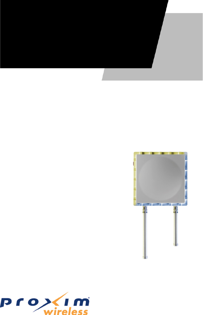
AP-4000MR-LR
Outdoor Access Point
Software Version 3.3
Part Number 72935 r1 (Print version)
Part Number 72933 r1 (CD version)
Quick Install

Page 2 Copyright © 2006 Proxim Wireless
CONTENTS
Notices ........................................................................... 2
Copyright .............................................................................................2
Trademarks ..........................................................................................2
Introduction ................................................................... 3
Authorized Antennas ...................................................... 5
Package Contents ........................................................... 6
Hardware and Software Installation ............................... 8
Step 1: Choose a Location ......................................................................9
Step 2: Pre-Assemble the Hardware ...................................................... 10
Step 3: Connect the Cables .................................................................. 13
Step 4: Power on the Unit .................................................................... 15
Step 5: View LEDs............................................................................... 16
Step 6: Mount the Unit ........................................................................ 17
Step 7: Complete Installation ............................................................... 18
Step 8: Install Documentation and Software ........................................... 19
Unit Initialization ......................................................... 20
Logging In ......................................................................................... 22
Using the Setup Wizard ........................................................................ 23
Installing the Software ......................................................................... 24
Frequencies and Bandwidths ........................................ 26
2.4 GHz Frequencies and Bandwidths..................................................... 26
5.8 GHz Frequencies and Bandwidths..................................................... 26
Technical services and support ..................................... 27
Support Options .................................................................................. 27
NOTICES
Copyright
Copyright ©2006 Proxim Wireless Corporation, San Jose, CA. All rights
reserved. Covered by one or more of the following U.S. patents: 5,231,634;
5,875,179; 6,006,090; 5,809,060; 6,075,812; 5,077,753. This manual and
the software described herein are copyrighted with all rights reserved. No
part of this publication may be reproduced, transmitted, transcribed, stored in
a retrieval system, or translated into any language in any form by any means
without the written permission of Proxim Wireless Corporation.
Trademarks
ORiNOCO and Proxim are registered trademarks, and the Proxim logo is a
trademark, of Proxim Wireless Corporation. All other trademarks mentioned
herein are the property of their respective owners.

All rights reserved Page 3
INTRODUCTION
The AP-4000MR-LR is a ruggedized tri-mode AP optimized for outdoor
deployments. It is equipped with one embedded 802.11a radio and one
embedded 802.11b/g radio, enabling simultaneous support of 802.11a,
802.11b, and 802.11g clients as well as Mesh operation on either the 2.4 or 5.8
GHz band.
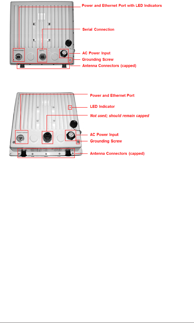
There are two versions of the AP-4000MR-LR hardware. Differences between
hardware versions are highlighted in this manual as necessary. See Figure 1
and Figure 2.
You can verify which hardware version you are using through either the HTTP
Interface or CLI Interface. See the AP-4000MR-LR User Guide for information on
locating your hardware version number.
AP-4000MR-LR units can operate either using PoE with the combination DC
power supply/injector provided or directly from a 100 - 240 VAC power source
(AC cable ordered separately).
The units feature internal lightning and surge protection on the AC and DC
power ports, the Ethernet port, and on both antenna ports. External antenna
lightning protection is not needed.
Note:
On R1 versions, internal lightning and surge protection is not available on
the Ethernet port.
Each unit is equipped with:
Power/Ethernet port: used for Ethernet connection and Power over
Ethernet (PoE) using the supplied power injector.
Serial connection: used for entering commands in the Command Line
Interface (CLI). R1 versions of the product are not equipped with a serial
connection.
LED indicator(s): dual LEDs used to indicate the power and operational
states of the unit. R1 versions of the product are equipped with a single
power LED.
AC power input: enables direct power from external AC power source.
External antenna connectors (two): one for 2.4 GHz operation, the
other for 5.8 GHz operation.
Grounding screws (two)
▪
▪
▪
▪
▪
▪

All rights reserved Page 5
AUTHORIZED ANTENNAS
This product does not contain internal antennas. At least one external antenna
must be used to make the product operational.
For the 2.4 and 5.8 GHz bands, the following antennas are authorized:
Antenna Type Max Antenna Gain
Authorized (2.4 GHz)
Max Antenna Gain
Authorized (5.8 GHz)
Omni-Directional 12 dBi or less 12 dBi or less
Flat Panel 18 dBi or less 28 dBi or less
Sector 17 dBi or less 18 dBi or less
Antennas used for the product must be x-mounted on permanent structures.
WARNING!
The antenna(s) used for this device must be installed to provide a separa-
tion distance of at least 123 cm (4 feet) from all persons and must not be
co-located or operate in conjunction with any other antenna or transmitter.
WARNING!
The antenna(s) used for this device must be installed to provide a separa-
tion distance of at least 123 cm (4 feet) from all persons and must not be
co-located or operate in conjunction with any other antenna or transmitter.
Page 6 Copyright © 2006 Proxim Wireless
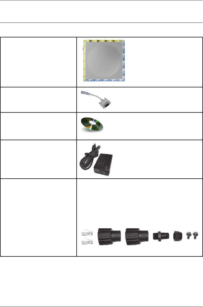
PACKAGE CONTENTS
Each AP-4000MR-LR shipment includes the items in the following table. Verify
that you have received all parts of the shipment.
Note:
Unless listed here, cables are not included with the unit.
AP-4000MR-LR Unit
RJ11 to DB9 serial
connector (not included
with R1 units)
Installation CD
Power Injector and Cord (1)
Cable Termination Kit Kit includes:
A. RJ45 connectors (2)
B. Sealing caps (2)
C. Sealing nut
D. Lock nut
E. Grounding screws (2)
A B C D E
All rights reserved Page 7
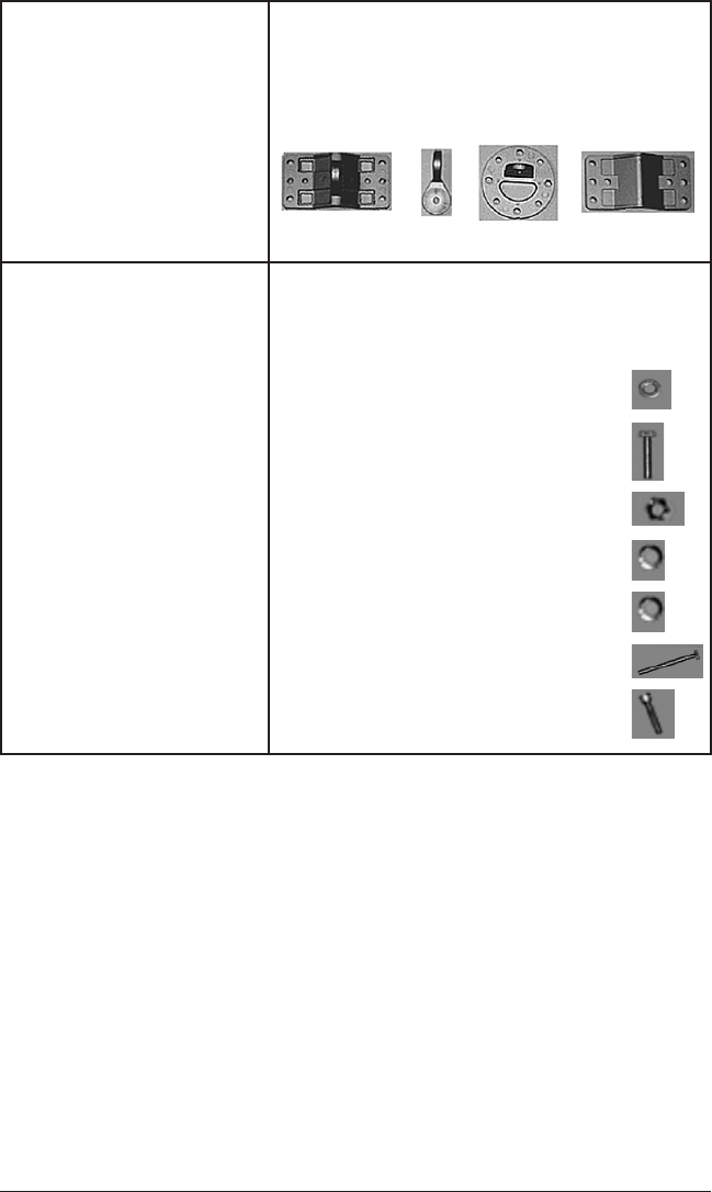
Mounting Kit Kit includes the following:
A. Mounting clamp for wall/pole
B. Extension arm
C. Mounting plate to enclosure
D. Mounting clamp for pole mounting
A B C D
Mounting Hardware The following mounting hardware is included
with mounting kit:
Qty. Description
6 ea Plain washer #5/16
2 ea. Hex cap screw NC 5/16-18 x 35
2 ea. Nut NC 5/16-18
4 ea. Helical spring lock washer # 1/4
4 ea. Helical spring lock washer #5/16
2 ea Hex cap screw NC 5/16-18 x 80
4 ea. 68764, Screw, Machine, Pan,
Phillips, 1/4”-20, 5/8”L

Page 8 Copyright © 2006 Proxim Wireless
HARDWARE AND SOFTWARE INSTALLATION
Notes:
Be sure to read the Release Notes le on the product CD as it contains
software version and driver information that may not have been available
when this document was produced.
Equipment is to be used with, and powered by, the power injector provided
or by a power injector that meets these requirements:
UL-Listed/ITE (NWGQ)
Limited Power Source Output per UL/IEC 60950
CE-marked
Approved for Power-over-Ethernet
Rated output, 48 Vdc/0.42 A
Pinout follows 802.3af standard for mid-span devices
▪
▪
–
–
–
–
–
–
IMPORTANT!
Before installing this product, see Safety and Regulatory Compliance
Information on the product CD for important information.
IMPORTANT!
Before installing this product, see Safety and Regulatory Compliance
Information on the product CD for important information.
IMPORTANT!
All AP-4000MR-LR units must be installed by a suitably trained profession-
al installation technician or by a qualied installation service.
IMPORTANT!
All AP-4000MR-LR units must be installed by a suitably trained profession-
al installation technician or by a qualied installation service.
WARNING!
To ensure proper grounding, use the hole at the bottom point on the back
of each unit and the provided grounding screws to attach a ground wire of
at least 10 AWG stranded to each unit. This wire must be as short as pos-
sible and must be connected to a low-impedance earth ground. Use proper
wire grounding techniques in accordance with local electric codes.

All rights reserved Page 9
Step 1: Choose a Location
To make optimal use of the unit, you must nd a suitable location for the
hardware. The range of the radio unit largely depends upon the position of the
antenna. Proxim recommends you do a site survey, observing the following
requirements, before mounting the hardware.
The location must allow easy disconnection of power to the radio if
necessary.
Air must be able to ow freely around the hardware.
The radio unit must be kept away from vibration and excessive heat.
The installation must conform to local regulations at all times.
The units are designed to directly mount to a pole or wall. Using the supplied
brackets and hardware, you can mount them to a 1.25 inch to 4.5-inch pole
(outside diameter). Using just one of the mounting brackets, you can mount
the units to a wall or other at surface.
Caution!
Proxim recommends the use of a lightning arrestor at the building
ingress point. You can purchase the Proxim Lightning Protector; see
the documentation that comes with the unit for more information
and installation instructions.
▪
▪
▪
▪
Page 10 Copyright © 2006 Proxim Wireless
Step 2: Pre-Assemble the Hardware
Unpack the unit and accessories from the shipping box.
Note the Ethernet and MAC addresses of the unit, as well as the serial
number; these addresses may be used when conguring the unit.
Note:
The serial number is required to obtain support from Proxim. Keep this
information in a safe place.
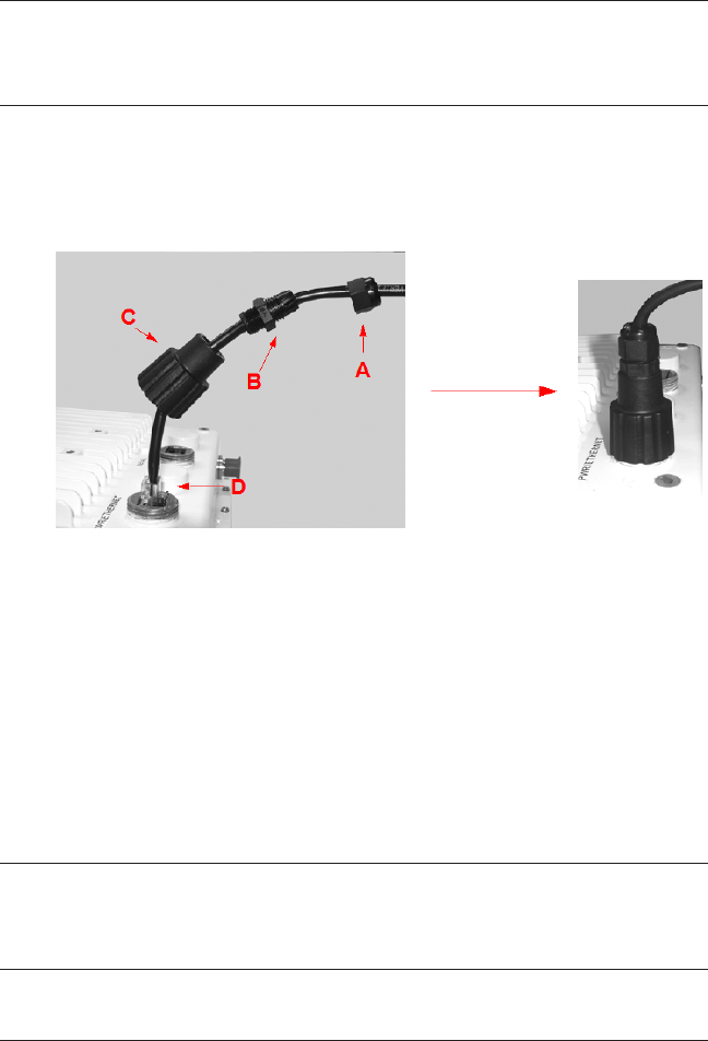
You will be attaching an outdoor-rated 24 AWG CAT5 cable (diameter .114
to .250 inches/2.9 to 6.4 mm) (not provided) to the Power-over-Ethernet
port on the back of the unit later in the installation procedure. First, you
must construct the cable and assemble the waterproong cable covers as
described in the following steps:
i. Slide the sealing nut (A) over the bare end of the CAT5 cable.
ii. Slide the lock nut (B) over the bare end of the CAT5 cable.
iii. Slide the RJ45 sealing cap (C) over the bare end of the CAT5 cable.
iv. Terminate the RJ45 connector to the CAT5 cable. Insert into the
mating RJ45 connector (D).
v. Slide the RJ45 sealing cap (C) over the RJ45 connector and thread
onto enclosure. Hand tighten.
vi. Thread the lock nut (B) onto sealing cap (C), and hand tighten.
vii. Thread the sealing nut (A) onto the lock nut (B), and hand tighten.
Caution!
Hand-tighten only. Torque values for nal installation are provided
in Step 7: Complete Installation.
1.
2.
3.
All rights reserved Page 11
Caution!
The sealing nut (A) must not be tightened until the sealing cap (C)
over the RJ45 connector has been tightened to the unit during nal
installation; otherwise, the Ethernet cable may twist and become
damaged.
Notes:
The cable must feed through all parts of the weatherproof cap before the
RJ45 is crimped on the outdoor Ethernet a cable.
The cable between the power injector and the unit must be a straight-
through Ethernet cable (without crossover).
Due to variance in CAT5 cable diameter, termination techniques of the
installer, and the application of proper tightness of the connectors, it
is strongly recommended that the CAT5 cable connector and the serial
connector cap are further secured by external weatherproong (in addition
to the antenna N connector, where applicable). Butyl weatherproong tape
is the preferred material for securing any external connector.
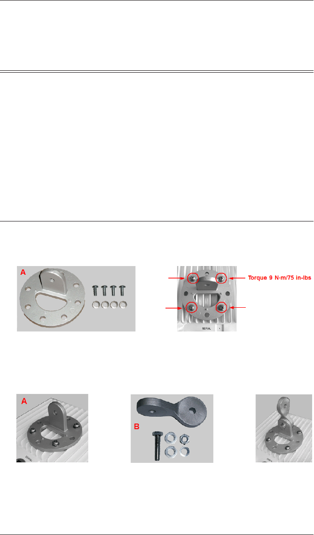
Attach the mounting plate (A) using the provided screws and washers
(Torque 9 N∙m/75 in-lbs), such that the unit’s antenna will be vertically or
horizontally polarized when mounted.
Attach the extension arm (B) to mounting piece (A) with the screw, nut,
and washers provided, as shown below. The extension arm gives the unit
more possible tilt, letting you adjust for azimuth or elevation over a larger
angle.
▪
▪
▪
4.
5.
Page 12 Copyright © 2006 Proxim Wireless
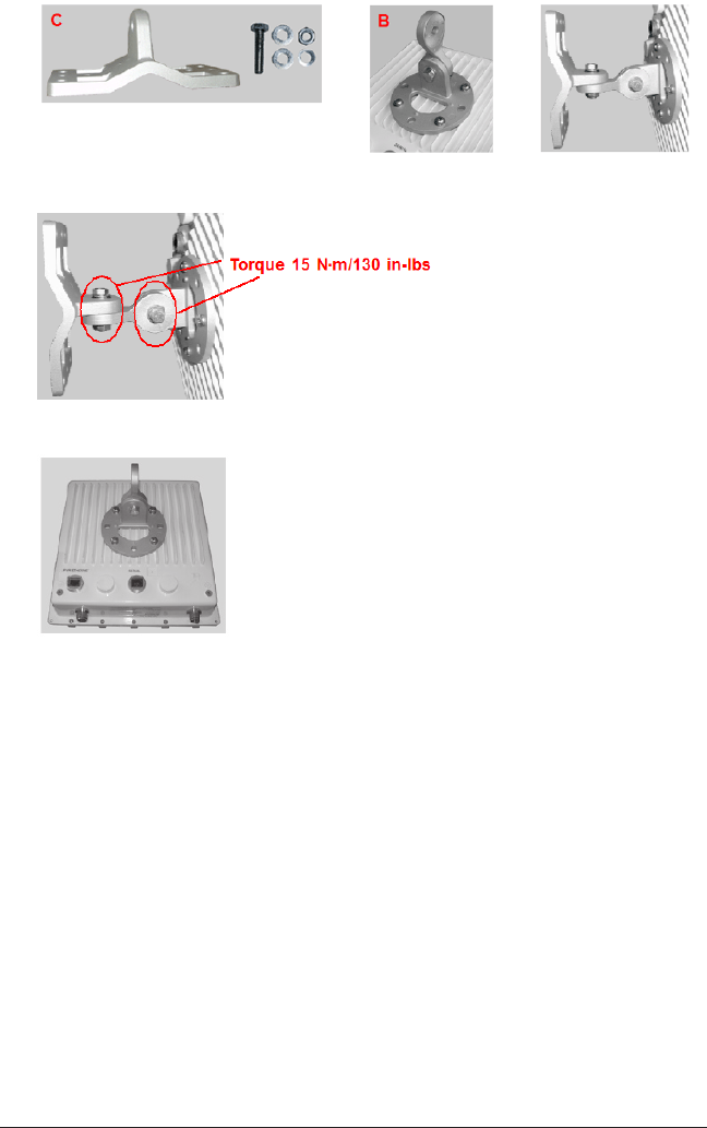
Attach the mounting bracket (C) to extension arm (B) with the screw, nut,
and washers provided.
Tighten assembly (Torque 15 N∙m/130 in-lbs).
The following gure shows the full assembly attached to the unit:
6.
7.
All rights reserved Page 13
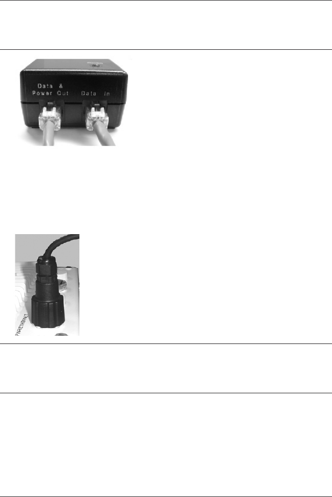
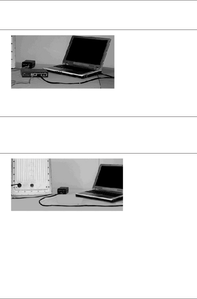
Step 3: Connect the Cables
If you have not already done so, connect the normal RJ45 connector on an
outdoor-rated CAT5 cable to the “Data and Power Out” port on the power
injector.
Note:
On R1 versions, connect the cable to the port labeled “J1 Antenna” on the
power injector (not pictured). This port has 48 VDC power on the RJ45.
Attach the other end of the CAT5 cable with RJ45 connector to the Power
and Ethernet port on the back of the unit (see the following gure). Note
that the rst attachment of this cable is meant to verify operation and
congure the unit; the nal attachment (with proper torque values) and
weatherproong are to be done after the unit has been installed in the
location at which it will operate (See Step 7: Complete Installation).
Caution!
Do not over-tighten the connector nuts; do not use a wrench to
tighten the connectors!
1.
2.
Page 14 Copyright © 2006 Proxim Wireless
To connect the unit through a hub or a switch to a PC, use a straight-
through Ethernet cable between the network interface card in the PC and
the hub, and between the hub and the RJ45 “Data In” port on the PoE
adapter.
Note:
On R1 units, connect the cable between the hub and the RJ45 “J2 PC/
Router” port on the power injector (not pictured).
If you are connecting the PC directly to the unit, use a crossover Ethernet
cable between the network interface card in the PC and the RJ45 “Data In”
port on the power injector.
Note:
On R1 units, connect the cross-over cable between the network interface
card in the PC and the and the RJ45 “J2 PC/Router” port on the power
injector (not pictured).
3.

All rights reserved Page 15
Step 4: Power on the Unit
The power injector provides Power-over-Ethernet (PoE), supplying electricity
and wired connectivity to the unit over a single 24 AWG CAT5 (diameter .114 to
.250 inches/2.9 to 6.4 mm). The unit is not 802.3af-compatible. Always use the
supplied power injector to ensure that the unit is powered properly. Note that
the Active Ethernet module provides +48 VDC over a standard CAT5 Ethernet
cable.
Once you have connected the power injector to the Ethernet cabling and
plugged the power injector cord into an AC outlet, the unit is powered on.
There is no ON/OFF switch on the unit. To remove power, unplug the AC cord
from the AC outlet or disconnect the RJ45 connector from the “Data and Power
Out” port on the power injector.
Note:
On R1 units, remove power by unplugging the AC cord from the AC outlet or
disconnecting the RJ45 connector from the “J1/Antenna” port on the power
injector.
Depressing the Reload button (on the side of the power injector) for ve
seconds during power-up remotely resets the radio to its factory default
settings. You will need to use the end of a pin or paperclip to depress the
button.
Note:
Power injectors supplied with R1 units are not equipped with a Reload
button.
Caution!
R1 units: if you connect the “Antenna” jack to your router/switch,
it will inject 48 VDC on the normally unused pins on the RJ45. This
may damage the terminating resistors in your router/switch on the
unused pins.
Page 16 Copyright © 2006 Proxim Wireless
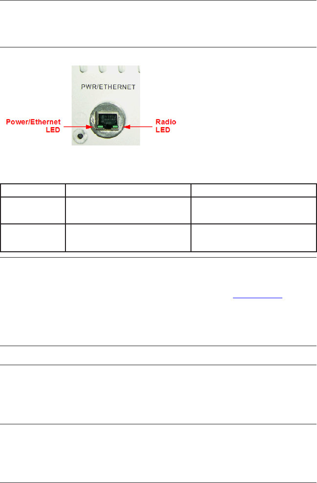
Step 5: View LEDs
On most units, the LEDs are present at the unit’s Ethernet connector; unscrew
the watertight cap if necessary to view the LEDs.
NOTE:
Make sure the domed sealing nut is loose before unscrewing the cap or the
Ethernet cable may be twisted and damaged.
When the unit is powered on, it performs startup diagnostics. When startup is
complete, the LEDs show the unit’s operational state, as follows:
LED State Power/Ethernet LED Radio LED
Blinking Green Power is on, unit is booting up,
Ethernet link is down.
Radios are being initialized.
Steady Green Power is on, Ethernet link is up. Radios are being operational.
Note:
On R1 units, there is one LED. It is the power LED that appears in the back
of the unit, between the cooling ns on the right side. (See Figure 2.)
On power-up, the LED ashes red during initial start-up, and then turns
solid red while booting. After a successful boot, it becomes solid green to
indicate normal operation.
Caution!
Before applying power to the units, make sure that a proper load or
antenna is connected to each N-female jack to minimize the chance
of damaging the RF power ampliers.
All rights reserved Page 17
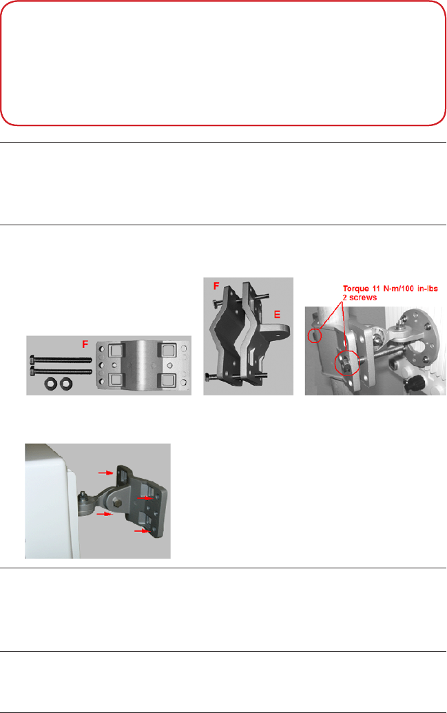
Step 6: Mount the Unit
Caution:
To ensure that water does not gather around the antenna
connectors, mount the unit with the antenna connectors facing
downward.
To pole-mount, insert screws through bracket F and fasten around pole to
bracket E and secure (Torque 11 N.m/100 in-lbs).
To wall-mount the unit, mount bracket (E) to wall using 4 screws (not
provided), as shown:
Note:
At the end of the installation, the Ethernet and serial ports must be made
waterproof by installing the caps. Be careful not to over-tighten the caps as
damage to the cable may occur.
1.
2.
IMPORTANT!
If the AP is going to be used as part of a Mesh network, you will need to
perform initial conguration of the parameters mentioned in the Prereq-
uisites section of this AP-4000MR-LR User Guide before you mount the
AP. See the User Guide for more information on conguring these param-
eters.
Page 18 Copyright © 2006 Proxim Wireless
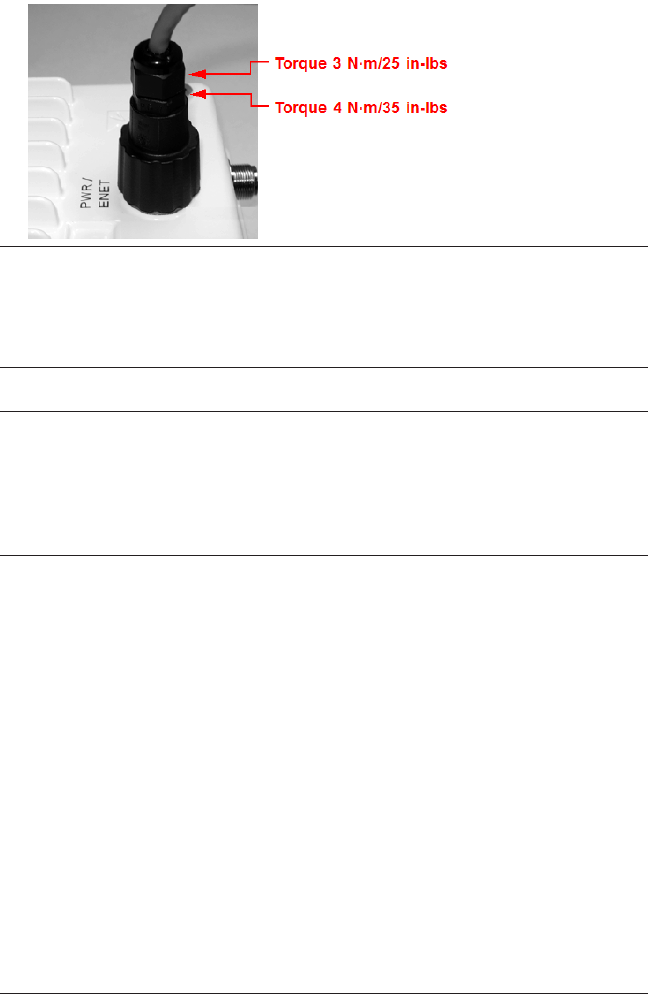
Step 7: Complete Installation
Tighten the sealing nut (Torque 3 N∙m/25 in-lbs) and lock nut (Torque
4 N∙m/35 in-lbs).
CAUTION!
Do not over-tighten! Over-tightening can cause the CAT5 cable to
become pinched and can subsequently damage the power injector
or the unit.
Tighten the RJ45 sealing cap.
CAUTION!
Be sure you have re-installed the waterproof caps on the serial and
Ethernet port connections. It is also good installation practice to
use Butyl weatherproong tape to seal the caps, as this adds an
extra layer of protection.
1.
2.

All rights reserved Page 19
Step 8: Install Documentation and Software
To install the documentation and software on a computer or network:
Place the CD in a CD-ROM drive. The installer normally starts
automatically. (If the installation program does not start automatically,
click setup.exe on the installation CD.)
Follow the instructions displayed on the installer windows. The following
documentation and software products are installed:
Available from Start > All Programs > ORiNOCO > AP4000MR-LR:
ScanTool program
AP-4000MR-LR Online Help
AP-4000MR-LR User Guide
Available from C:\Program Files\ORiNOCO\AP4000MR-LR:
ScanTool program
AP-4000MR-LR Read Me
License agreement
Available from C:\Program Files\ORiNOCO\AP4000MR-LR\PDF:
AP-4000MR-LR User Guide
AP-4000MR-LR Quick Install Guide
AP-4000MR-LR Antenna Installation Guide
AP-4000MR-LR Recommended Antennas
AP-4000MR-LR Safety and Regulatory Compliance Guide
Available from C:\Program Files\ORiNOCO\AP4000MR-LR\HTML:
AP-4000MR-LR Online Help (double-click on index.htm to launch)
Available from Xtras C:\Program Files\ORiNOCO\AP4000MR-LR\
Xtras:
TFTP Server
Acrobat Reader
1.
2.
▪
–
–
–
▪
–
–
–
▪
–
–
–
–
–
▪
–
▪
–
–

Page 20 Copyright © 2006 Proxim Wireless
UNIT INITIALIZATION
Using ScanTool
ScanTool is a software utility that is included on the installation CD-ROM. It is
an initial conguration tool that allows you to nd the IP address of an Access
Point by referencing the MAC address in a Scan List, or to assign an IP address
if one has not been assigned.
The tool automatically detects the Access Points installed on your network,
regardless of IP address, and lets you congure each unit’s IP settings. In
addition, you can use set initial device parameters that will allow the AP to
retrieve a new software to an AP that does not have a valid software image
installed.
To access the HTTP interface and congure the AP, the AP must be assigned
an IP address that is valid on its Ethernet network. By default, the AP is
congured to obtain an IP address automatically from a network Dynamic Host
Conguration Protocol (DHCP) server during boot-up. If your network contains a
DHCP server, you can run ScanTool to nd out what IP address the AP has been
assigned. If your network does not contain a DHCP server, the Access Point’s
IP address defaults to 169.254.128.132. In this case, you can use ScanTool to
assign the AP a static IP address that is valid on your network.
Scan Tool Instructions
Power up the AP (if not already powered on).
Double-click the ScanTool icon on the Windows desktop to launch the
program. If the icon is not on your desktop, click Start > All Programs >
ORiNOCO > AP40000MR-LR > ScanTool.
Note:
If your computer has more than one network adapter installed, you will be
prompted to select the adapter that you want ScanTool to use before the
Scan List appears. You can use either an Ethernet or wireless adaptor.
If prompted, select an adapter and click OK. You can change your adapter
setting at any time by clicking the Select Adapter button on the Scan List
screen.
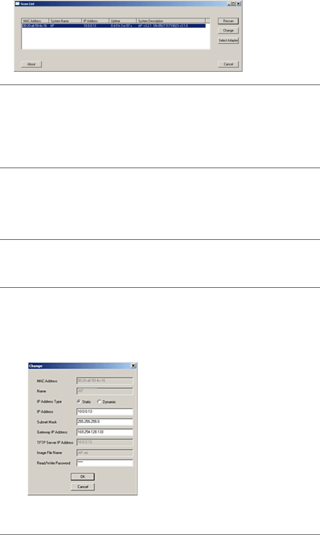
ScanTool scans the subnet and displays all detected Access Points. The
ScanTool’s Scan List screen appears, as shown in the following example.
1.
2.
All rights reserved Page 21
Note:
If your Access Point does not appear in the Scan List, click the Rescan
button to update the display. If the unit still does not appear in the list, see
the Troubleshooting chapter in the AP-4000MR-LR User Guide for suggestions.
Note that after rebooting an Access Point, it may take up to ve minutes for
the unit to appear in the Scan List.
Do one of the following:
If the AP has been assigned an IP address by a DHCP server on the
network, write down the IP address and click Cancel to close ScanTool.
Proceed to the Logging In section below for information on how to access
the HTTP interface using this IP address.
Note:
Mesh APs must be congured with static IP addresses. To assign the AP a
static IP address, follow the steps below.
If the AP has not been assigned an IP address (in other words, the unit
is using its default IP address, 169.254.128.132), follow these steps to
assign it a static IP address that is valid on your network:
Highlight the entry for the AP you want to congure.
Click the Change button. The Change screen appears.
Set IP Address Type to Static.
3.
▪
▪
a.
b.
c.
Page 22 Copyright © 2006 Proxim Wireless
Enter a static IP Address for the AP in the eld provided. You must
assign the unit a unique address that is valid on your IP subnet.
Enter your network’s Subnet Mask.
Enter your network’s Gateway IP Address.
Enter the SNMP read/write password in the Read/Write Password
eld. For new units, the default password is public.
Click OK to save your changes. The Access Point will reboot
automatically and any changes you made will take effect.
When prompted, click OK a second time to return to the Scan List
screen.
Click Cancel to close the ScanTool.
Logging In
Once the AP has a valid IP Address and an Ethernet connection, you may use
your web browser to monitor and congure the AP. (To congure and monitor
using the command line interface, see the AP-4000MR-LR User Guide)
Open a Web browser on a network computer.
If necessary, disable the browser’s Internet proxy settings.
Enter the Access Point’s IP address in the browser’s Address eld and
press Enter or Go. This is either the dynamic IP address assigned by a
network DHCP server or the static IP address you manually congured. See
Using ScanTool for information on how to determine the unit’s IP address
and manually congure a new IP address, if necessary.
Note:
Mesh APs must be congured with static IP addresses.
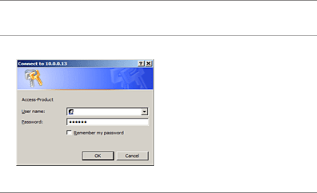
The Enter Network Password screen appears.
d.
e.
f.
g.
h.
i.
j.
1.
2.
3.
4.
All rights reserved Page 23
Enter the HTTP password in the Password eld. Leave the User Name
eld blank. For new units, the default HTTP password is public.
If you are logging on for the rst time the Setup Wizard will launch
automatically.
Note
Setup Wizard will not relaunch on subsequent logins. To force the Setup
Wizard to launch upon login, click htManagement > Services and choose
Enable from the Setup Wizard drop down menu.
To congure the AP using the Setup Wizard, see Using the Setup
Wizard, below. To congure the AP without using the Setup Wizard,
click Exit. Upon clicking Exit, the System Status screen will appear. See
the “Advanced Conguration” chapter in the AP-4000MR-LR User Guide for
conguration instructions.
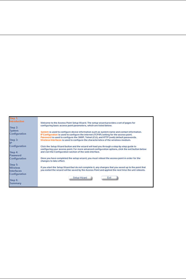
Using the Setup Wizard
The Setup Wizard provides step-by-step instructions for how to congure
the Access Point’s basic operating parameters, such as Network Name, IP
parameters, system parameters, and management passwords.
Click Setup Wizard to begin. The Setup Wizard supports the following
navigation options:
Save & Next Button: Each Setup Wizard screen has a Save & Next
button. Click this button to submit any changes you made to the unit’s
parameters and continue to the next page. The instructions below
describe how to navigate the Setup Wizard using the Save & Next
buttons.
Navigation Panel: The Setup Wizard provides a navigation panel
on the left-hand side of the screen. Click the link that corresponds to
the parameters you want to congure to be taken to that particular
5.
6.
1.
▪
▪

Page 24 Copyright © 2006 Proxim Wireless
conguration screen. Note that clicking a link in the navigation panel
will not submit any changes you made to the unit’s conguration on the
current page.
Exit: To exit from the Setup Wizard at any time, click Step 1:
Introduction on the navigation panel, and then click the Exit button.
CAUTION:
If you exit from the Setup Wizard, any changes you submitted (by
clicking the Save & Next button) up to that point will be saved to the
unit but will not take effect until it is rebooted.
Follow the prompts provided by the Setup Wizard to perform an initial
conguration of the AP. See the AP-4000MR-LR User Guide for more detailed
Setup Wizard instructions and for Advanced Conguration instructions.
Installing the Software
Proxim periodically releases updated software for the AP-4000MR-LR on its
support Web site, http://support.proxim.com. Proxim recommends that you
check the Web site for the latest updates after you have installed and initialized
the unit.
Download the Software
In your web browser, go to http://support.proxim.com.
If prompted, create an account to gain access.
Note:
The Knowledgebase is available to all Web site visitors. First-time users will
be asked to create an account to gain access.
Click Search Knowledgebase.
In the Search Knowledgebase eld, enter 2334.
From the Search By drop-down menu, select Answer ID.
Click Search.
Click on the appropriate link in the Summary column to download the
software.
Click on the appropriate link to download the software.
Install the Software
Enter the Access Point’s IP address in the browser’s Address eld and press
Enter or Go.
▪
2.
1.
2.
3.
4.
5.
6.
7.
8.
1.

All rights reserved Page 25
Click Commands > Update AP > via HTTP. The Update AP via HTTP
screen will be displayed.
From the File Type drop-down menu, select Image.
Use the Browse button to locate or manually type in the name of the
le (including the le extension) you downloaded from the Proxim
Knowledgebase. If typing the le name, you must include the full path and
the le extension in the le name text box.
To initiate the HTTP Update operation, click the Update AP button.
A warning message advises you that a reboot of the device will be required
for changes to take effect.
Click OK to continue with the operation or Cancel to abort the operation.
If the operation is unsuccessful, you will receive an error message. See
the AP-4000MR-LR User Guide for more information. If the operation is
successful, you will receive a conrmation message.
Reboot the AP as follows:
Click Commands > Reboot.
Enter 0 in the Time to Reboot eld.
Click OK.
Note:
For instructions on downloading the software via a TFTP Server or the CLI
Interface, see the AP-4000MR-LR User Guide.
2.
3.
4.
5.
6.
7.
8.
a.
b.
c.

Page 26 Copyright © 2006 Proxim Wireless
FREQUENCIES AND BANDWIDTHS
2.4 GHz Frequencies and Bandwidths
Channel Center Frequency (MHz) 20 MHz
1 2412
2 2417
3 2422
4 2427
5 2432
6 2437
7 2442
8 2447
9 2452
10 2457
11 2462
= Occupied bandwidth for specified center frequency.
5.8 GHz Frequencies and Bandwidths
Channel Center Frequency (MHz) 20 MHz
149 5745
153 5765
157 5785
161 5805
165 5825
= Occupied bandwidth for specified center frequency.

All rights reserved Page 27
TECHNICAL SERVICES AND SUPPORT
If you are having trouble utilizing your Proxim product, please review the AP-
4000MR-LR User Guide and the additional documentation provided with your
product.
If you require additional support, please refer to the “Technical Services
and Support” chapter in the AP-4000MR-LR User Guide for details about the
information you will need to gather before using the Support Options listed
below.
Support Options
Proxim eService Web Site Support
The Proxim eService Web site is available 7x24x365 at:
http://support.proxim.com
Telephone Support
Contact technical support via telephone as follows:
Domestic: 866-674-6626
International: +1-408-542-5390
Hours of Operation
North America: 8 a.m. to 5 p.m. PST, Monday through Friday
EMEA: 8 a.m. to 5 p.m. GMT, Monday through Friday
ServPak Support
Proxim understands that service and support requirements vary from customer
to customer. In recognition of these varying requirements we have developed
a support program called ServPak. ServPak is a program of Enhanced Service
Options that can be purchased individually or in combinations to meet your
needs.
Advanced Replacement
Extended Warranty
7x24x365 Technical Support
Priority Queuing
To learn more, please call Proxim Support at +1-408-542-5390 or send an
email to servpak@proxim.com. To purchase ServPak support services, please
contact your authorized Proxim distributor.
▪
▪
▪
▪
▪
▪
▪
▪
▪