Proxim Wireless A09UCF UNII/ISM Radio Network Equipment User Manual Backing down from TNG CCI 2
Proxim Wireless Corporation UNII/ISM Radio Network Equipment Backing down from TNG CCI 2
Contents
- 1. Users Manual I
- 2. Users Manual II
- 3. Professional Installation Manual
- 4. Revised Professional Installation Manual
Revised Professional Installation Manual

Tsunami MP.11a
Antenna Installation Guide
CPN 65756
Issue Date: 01 August 2003

Tsunami MP.11a Antenna Installation Guide
COPYRIGHT
©2003 Proxim Corporation, Sunnyvale, CA. All rights reserved. Covered by one or more of the following
U.S. patents: 5,231,634; 5,875,179; 6,006,090; 5,809,060; 6,075,812; 5,077,753. This manual and the
software described herein are copyrighted with all rights reserved. No part of this publications may be
reproduced, transmitted, transcribed, stored in a retrieval system, or translated into any language in any form
by any means without the written permission of Proxim Corporation.
TRADEMARKS
Tsunami, Proxim, and the Proxim logo are trademarks of Proxim Corporation. All other trademarks
mentioned herein are the property of their respective owners.
REGULATORY INFORMATION
The Tsunami outdoor antenna solution must be installed and used in strict accordance with the instructions as described
in this Antenna Installation Guide.
Note: Radio approvals for the Tsunami outdoor antenna solution are valid only when using the exact combination of
outdoor antenna cabling components and antennas as listed in this Tsunami MP.11a Antenna Installation
Guide.
Using other combinations of parts and components in outdoor antenna solutions will void the radio type
approval and may be in violation of local radio regulations.
Proxim Corporation and its authorized resellers or distributors are not liable for any damage or violation of
government regulations that may arise from failing to comply with these guidelines.
This document provides regulatory information for the following wireless products:
▪ Tsunami MP.11a Base Station Unit, Subscriber Unit, Residential Subscriber Unit
This device complies with Part 15 of the FCC Rules. Operation is subject to the following two conditions:
(1) This device may not cause harmful interference
(2) This device must accept any interference received, including interference that may cause undesired operation.
Changes or modifications not expressly approved by Proxim Corporation could void the user's authority to operate the
equipment.
This equipment has been tested and found to comply with the limits for a Class B digital device, pursuant to Part 15 of
the FCC Rules. These limits are designed to provide reasonable protection against harmful interference in a residential
installation.
This equipment generates, uses, and can radiate radio frequency energy and, if not installed and used in accordance
with the instructions, may cause harmful interference to radio communications. However, there is no guarantee that
interference will not occur in a particular installation. If this equipment does cause harmful interference to radio or
television reception (which can be determined by turning the equipment off and on), the user is encouraged to attempt to
correct the interference by one or more of the following measures:
▪ Reorient or relocate the receiving antenna.
▪ Increase the separation between the equipment and receiver.
▪ Connect the equipment into an outlet on a circuit different from that to which the receiver is connected.
▪ Consult the dealer or an experienced radio or television technician for help.
This product must be fixed/mounted on permanent structures with a separation distance of at least two meters from all
persons during normal operation.
Notices 2
CPN 65756 Issue Date: 01 August 2003

Tsunami MP.11a Antenna Installation Guide
Contents
Copyright............................................................................................................................................................... 2
Trademarks ........................................................................................................................................................... 2
Regulatory Information .......................................................................................................................................... 2
Contents...................................................................................................................................................................... 3
About This Book......................................................................................................................................................... 5
Who Should Use This Guide ................................................................................................................................. 5
Finding Additional Information............................................................................................................................... 5
About the Tsunami MP.11a................................................................................................................................... 6
Point-to-Point Link.......................................................................................................................................... 6
Point-to-Multipoint Network ............................................................................................................................ 7
Chapter 1. Preparing for Installation........................................................................................................................ 8
Site Prerequisites .................................................................................................................................................. 8
Overview of the Indoor Installation ........................................................................................................................ 8
Tsunami MP.11a Hardware ........................................................................................................................... 8
Cable System............................................................................................................................................... 10
Placement of the Surge Arrestor.................................................................................................................. 10
Antenna Cable Route................................................................................................................................... 11
Overview of the Outdoor Installation ................................................................................................................... 12
Antenna Placement...................................................................................................................................... 12
Antenna Mounting ........................................................................................................................................ 14
Chapter 2. Determining Range and Clearance...................................................................................................... 16
Determining the Outdoor Range ......................................................................................................................... 16
Maximum Range.......................................................................................................................................... 17
Cable Factor ................................................................................................................................................ 17
Clearance Factor.......................................................................................................................................... 18
Calculations......................................................................................................................................................... 20
Calculating Received Signal Level and Link Budget .................................................................................... 20
Chapter 3. Installing the Antenna .......................................................................................................................... 26
Planning Antenna Installation.............................................................................................................................. 26
Safety Precautions .............................................................................................................................................. 26
Installation Overview ........................................................................................................................................... 27
Mounting the Antenna ......................................................................................................................................... 28
Connecting the Antenna Cable .................................................................................................................... 28
Sealing the Cable Connectors ..................................................................................................................... 29
Grounding System ....................................................................................................................................... 29
Antenna Alignment....................................................................................................................................... 30
Antenna Polarization .................................................................................................................................... 30
Antenna Cable Routing ................................................................................................................................ 30
Before Climbing the Roof... ................................................................................................................................. 30
Appendix A. Outdoor Antenna Equipment............................................................................................................ 31
Antenna List ........................................................................................................................................................ 32
Appendix B. Antenna Cabling System .................................................................................................................. 33
Outdoor Cabling Components............................................................................................................................. 33
Selecting the Correct Connector Type ................................................................................................................ 33
Surge Arrestor..................................................................................................................................................... 35
Low-Loss Antenna Cable .................................................................................................................................... 36
Appendix C. Recommended Antennas.................................................................................................................. 39
18 dBi HIGH GAIN DIRECTIONAL PANEL ANTENNA for 5.25 to 5.875 GHz ................................................... 39
Specifications ............................................................................................................................................... 39
Dimensions .................................................................................................................................................. 40
Pattern ......................................................................................................................................................... 40
15 dBi HIGH GAIN DIRECTIONAL PANEL ANTENNA for 5 GHz ...................................................................... 43
General Description ..................................................................................................................................... 43
Mounting Instructions ................................................................................................................................... 43
Specifications ............................................................................................................................................... 44
Pattern ......................................................................................................................................................... 44
23 dBi HIGH GAIN DIRECTIONAL PANEL ANTENNA for 5.8 GHz ................................................................... 45
Package Contents........................................................................................................................................ 45
Notices 3
CPN 65756 Issue Date: 01 August 2003

Tsunami MP.11a Antenna Installation Guide
Mounting ...................................................................................................................................................... 45
Specifications ............................................................................................................................................... 46
Pattern ......................................................................................................................................................... 47
Appendix D. Certified Outdoor Solutions.............................................................................................................. 49
Introduction ......................................................................................................................................................... 49
Selecting the Correct Cables............................................................................................................................... 49
Appendix E. Channel Frequencies ........................................................................................................................ 50
Support and Warranty.............................................................................................................................................. 51
Technical Support ............................................................................................................................................... 51
Warranty and Repair ........................................................................................................................................... 51
Figure 1. Point-to-Point Link ....................................................................................................................... 6
Figure 2. Point-to-Multipoint Network ......................................................................................................... 7
Figure 3. Cable Setup for Indoor Installation .............................................................................................. 9
Figure 4. Potential Obstacles for a Directional Antenna........................................................................... 13
Figure 5. Fresnel Zone.............................................................................................................................. 18
Figure 6. Clearance Factor Diagram ........................................................................................................ 19
Figure 7. Surge Arrestor ........................................................................................................................... 35
Table 1. Cable Factor ............................................................................................................................... 17
Table 2. Receiver Sensitivity and Minimum SNR for a Good Link ........................................................... 22
Table 3. Output Power Table for FCC ...................................................................................................... 23
Table 4. Output Power Table for ETSI...................................................................................................... 24
Table 5. Examples of Antenna Cable Loss Required per Regulatory Domain and Antenna Type ...........24
Table 6. Distance and Link Budget........................................................................................................... 25
Table 7. Antenna List ................................................................................................................................ 32
Table 8. Standard N-Type Connector Diagram ........................................................................................ 33
Table 9. Reverse Polarity-N Cabling Diagram.......................................................................................... 34
Table 10. Specifications: Surge Arrestor ................................................................................................. 36
Table 11. Specifications 6 m (20 ft) Antenna Cable ................................................................................. 37
Table 12. Specifications 15 m (50 ft) Antenna Cable ............................................................................... 37
Table 13. Specifications 22 m (75 ft) Antenna Cable ............................................................................... 38
Table 14. Specifications 15 m (50 ft) Extra Low Loss Antenna Cable...................................................... 38
Contents 4
CPN 65756 Issue Date: 01 August 2003

Tsunami MP.11a Antenna Installation Guide
About This Book
This Tsunami MP.11a Antenna Installation Guide explains how to install and set up an outdoor antenna with
the Tsunami MP.11a hardware.
This guide does not explain how to erect antenna masts, nor how to install a safety grounding system.
These prerequisites must be in place before installing the directional antenna.
WHO SHOULD USE THIS GUIDE
The installation of outdoor wireless links requires technical expertise. At the very least, you should be able to:
▪ Install and configure the network components, such as the Tsunami MP.11a hardware.
▪ Understand, or have a working knowledge of, installation procedures for network operating systems
using Microsoft Windows.
▪ Mount the outdoor antenna and surge arrestor. Antenna installation must be provided by professional
installers.
WARNING!
The Tsunami outdoor antennas are intended for mounting on a roof or on the side of a building.
Installation is not to be attempted by someone who is not trained or experienced in this type of work.
The antenna must be installed by a suitably trained professional installation technician. The site
prerequisites must be checked by a person familiar with the national electrical code and other
regulations governing this type of installation.
FINDING ADDITIONAL INFORMATION
Installing Tsunami MP.11a Hardware
Tsunami outdoor antennas typically are used in combination with Tsunami MP.11a systems. The
hardware installation of these devices is described in the installation guide included with each product.
Configuration and Management
The configuration and management of outdoor wireless links is done with management tools which come
with the Tsunami MP.11a systems. Some examples of management tools are:
º Web-based management
º Telnet
º Wireless Network Manager
Hardware Specifications
Tsunami MP.11a hardware and radio frequency specifications are described in the documentation that
comes with the product. Hardware specifications for the outdoor antennas, the cabling system, and the
surge arrestor are listed in Appendixes of this guide.
Additional Files on Your Software CD-ROM
All software CD-ROMs that come with your Tsunami products, include a readme.txt file. This file
contains information about the software version and drivers. You are advised to print and read the
readme.txt file prior to installing your Tsunami products, as it may contain additional information that
was not available when this document was printed.
About This Book 5
CPN 65756 Issue Date: 01 August 2003
Tsunami MP.11a Antenna Installation Guide
Other Sources of Information
All documentation listed above can be downloaded from the Proxim Support website:
http://www.expressresponse.com/proxim02. Visit the website regularly for the latest available
information and documentation, software updates and other Proxim news.
ABOUT THE TSUNAMI MP.11A
The Tsunami MP.11a lets you set up a wireless system based upon two basic topologies:
▪ Point-to-point link to connect one location to another
▪ Point-to-multipoint link to connect one location to two or more other locations.
A link between two locations always consists of a Base Station Unit and a Subscriber Unit. A Base Station
Unit can, depending upon its configuration, connect to one or more Subscriber Units; a Subscriber Unit,
however, can connect to only one Base Station Unit at any given time.
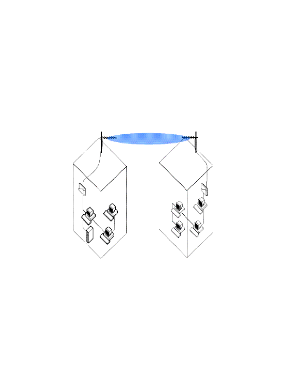
Point-to-Point Link
With a Base Station Unit and a Subscriber Unit, it is easy to set up a wireless point-to-point link as depicted
in the following figure.
Figure 1. Point-to-Point Link
The point-to-point link function lets you set up a connection between two locations as an alternative to:
▪ Leased lines in building-to-building connections
▪ Wired Ethernet backbones between wireless access points in hard-to-wire environments
About this Book 6
CPN 65756 Issue Date: 01 August 2003
Tsunami MP.11a Antenna Installation Guide
Point-to-Multipoint Network
To connect more than two buildings, you can choose to:
▪ Set up multiple point-to-point links, using multiple pairs of Base Station and Subscriber Units
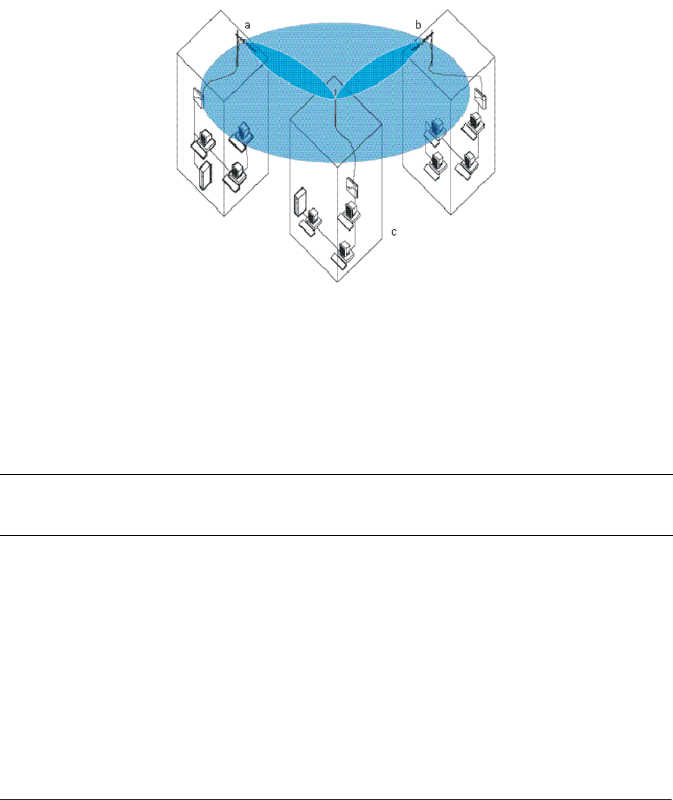
▪ Set up a single point-to-multipoint network using a single Base Station Unit and multiple Subscriber
Units, as depicted in the following figure.
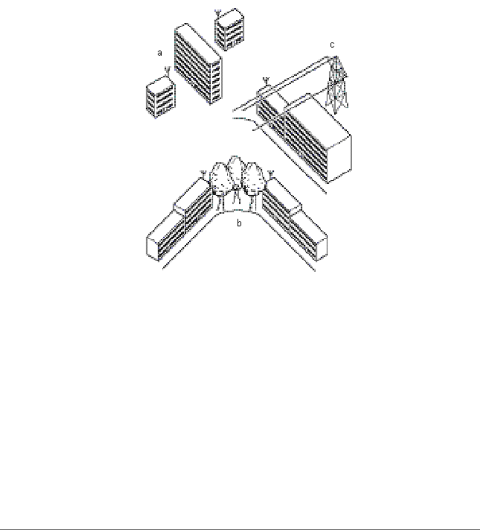
Figure 2. Point-to-Multipoint Network
The system in this figure is designed as follows:
▪ The central building (c) is equipped with the Base Station Unit, connected to either an omni-directional or
a wide angle antenna.
▪ The two other buildings (a and b) are both equipped with a Subscriber Unit connected to a directional
antenna.
Note: Depending upon local radio regulations and legislation, the outdoor antenna solutions described in
this document may not be available in all parts of the world. Consult “Appendix C. Certified Outdoor
Solutions” for more information.
About this Book 7
CPN 65756 Issue Date: 01 August 2003

Tsunami MP.11a Antenna Installation Guide
Chapter 1. Preparing for Installation
SITE PREREQUISITES
Review all requirements outlined within the following sections before starting the installation procedure:
▪ Overview of the Indoor Installation
▪ Overview of the Outdoor Installation
▪ Climbing the Roof
Prior to climbing on the roof or any other area where you intend to install the outdoor antenna, you are
advised to:
▪ Verify that you have arranged all safety measures for outdoor or rooftop installation.
▪ Verify that you have all equipment and tools required to install the outdoor antennas.
▪ Install and verify proper operation of the equipment.
OVERVIEW OF THE INDOOR INSTALLATION
The indoor installation of the link consists of the following components:
▪ The Tsunami MP.11a hardware
▪ A cable system
Tsunami MP.11a Hardware
There are three types of hardware devices to setup a wireless link:
▪ Tsunami MP.11a Base Station Unit (BSU)
▪ Tsunami MP.11a Subscriber Unit (SU)
▪ Tsunami MP.11a Residential Subscriber Unit (RSU)
Tsunami MP.11a
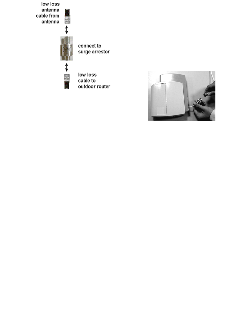
The following figure shows an overview of the cable setup for this outdoor antenna. When the MP.11a is not
mounted close to the entrance of the antenna cable into the building (where the surge arrestor must be
mounted), an additional cable between the MP.11a and the surge arrestor is needed, plus a female-female
converter connector. If the MP.11a is mounted close to the surge arrestor, the MP.11a can be connected
directly to the surge arrestor.
The deviation to the rule is the MP.11a RSU when the Window antenna is installed in an indoor location. This
does not require the use of a Surge Arrestor. The antenna can be connected directly to the MP.11a.
Chapter 1. Preparing for Installation 8
CPN 65756 Issue Date: 01 August 2003
Tsunami MP.11a Antenna Installation Guide
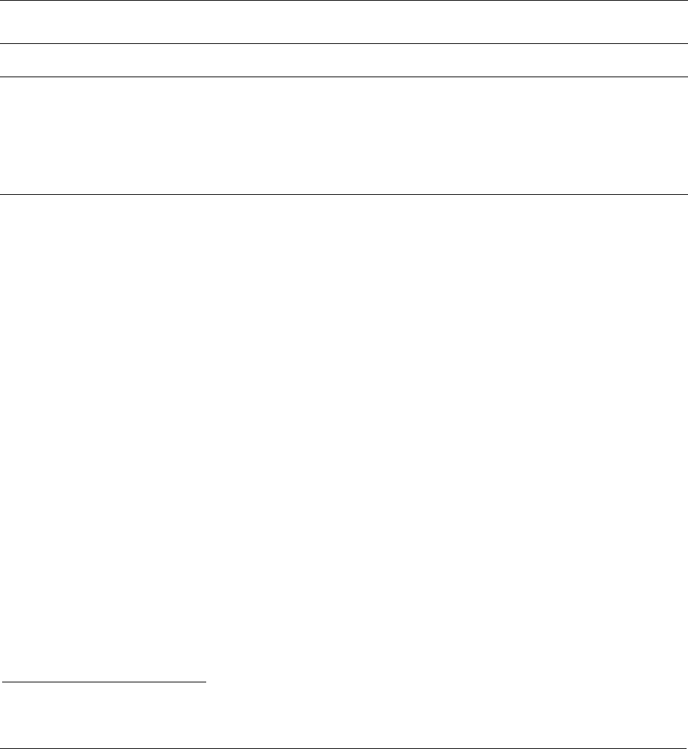
connect to N-type
male connector
pigtail extending
from MP.11a unit
Figure 3. Cable Setup for Indoor Installation
On each end of the wireless link you will require the following items:
▪ A Tsunami MP.11a Base Station or Subscriber Unit
▪ A low-loss antenna cable to connect the indoor installation to the surge arrestor (optional)
▪ Female-female converter connector (optional)
▪ A surge arrestor to protect your sensitive Tsunami MP.11a equipment from static discharge and
transients from the outdoor antenna system
▪ A low-loss antenna cable to connect the surge arrestor to the outdoor antenna
▪ Outdoor antenna
▪ A grounding system as described in “Grounding System” on page 16.
Placement of the Tsunami MP.11a Hardware
The electronics (power supply and unit) are designed for indoor mounting and operation. The ideal location
must satisfy the following requirements:
▪ The location provides a connection to a grounding type AC wall outlet (100-240 VAC), using the standard
power cord supplied with the unit. (Alternative power can be provided through Power over Ethernet.)
▪ The ground of the AC wall outlet must be connected to the same grounding system as the surge arrestor
and antenna mast (see “Grounding System” on page 16).
▪ The location must allow for easy disconnection of the Tsunami MP.11a hardware from the AC wall outlet.
▪ The location provides a connection to the network backbone (an Ethernet LAN cable that is connected to
a hub, bridge, or directly into a patch panel)
Chapter 1. Preparing for Installation 9
CPN 65756 Issue Date: 01 August 2003

Tsunami MP.11a Antenna Installation Guide
▪ The location is as close as possible to the point where the antenna cable will enter the building (see
“Placement of the Surge Arrestor” below).
▪ The ideal location has a temperature of 0-55 degrees Celsius and a maximum relative humidity (non-
condensing) of 95%.
CAUTION! The Tsunami MP.11a hardware, the surge arrestor, and the antenna mast must be
connected to the same grounding system.
Cable System
CAUTION! The Tsunami MP.11a products are designed for indoor installation. At all times the
location of the Tsunami MP.11a radio unit and power supply must be indoors, to protect
the unit from extreme weather conditions, excessive heat and humidity, and to keep the
unit free from vibration and dust. The antenna and surge arrestor can be placed
outdoors.
Prior to mounting the Tsunami MP.11a, you are advised to calculate carefully:
▪ The distance between the intended location of your Tsunami MP.11a hardware and the location of the
antenna mast
▪ The height of the antenna on the mast.
If the low-loss antenna cable is not long enough to cover this distance you can select another:
▪ Cable length from the Proxim Systems low-loss cable offering
▪ Location that satisfies the requirements listed previously to mount your Tsunami MP.11a hardware
As the length of the antenna cable may affect the actual range of your outdoor antenna installation, the last
option is preferred.
WARNING! You must not change the length of the low-loss antenna cable to a length shorter than
allowed by the radio’s certifications (see “Appendix C. Certified Outdoor Solutions “on
page 47. Shortening the cable will void the Proxim Corporation warranty and may
conflict with radio certifications or approvals.
How to install the Tsunami MP.11a hardware is described in Tsunami MP.11a Installation and Management,
which comes on the Tsunami MP.11a product CD.
Placement of the Surge Arrestor
The surge arrestor is an indispensable part of your outdoor antenna installation. It protects your sensitive
electronic equipment from transients or electro-static discharges at the antenna.
For optimal protection, the surge arrestor must be installed at a location that satisfies the following
requirements:
▪ A location as close to the location where the antenna cable will enter the building (see “Placement of the
Tsunami MP.11a Hardware” on page 9).
▪ The location allows for easy disconnection of the surge arrestor from the cable connected to the unit.
▪ The location provides a connection to the same grounding system as the Tsunami MP.11a hardware and
the outdoor antenna mast (as described in “Grounding System” on page 16).
Chapter 1. Preparing for Installation 10
CPN 65756 Issue Date: 01 August 2003

Tsunami MP.11a Antenna Installation Guide
Antenna Cable Route
The antenna cable must be connected from the antenna through the surge arrestor to the pigtail connector of
the MP.11a unit. To plan the route of the antenna cable, consider the following:
▪ Does the cable route require drilling through a wall or ceiling?
▪ Do you have a building plan of the desired location showing other cabling routes like electricity,
telephone or networking?
▪ Does the type of building materials require special drilling tools?
The cable should not be installed into tight positions, as bending or applying excessive force to the
connectors can damage the antenna cable. Always allow the cable to bend naturally around corners. The
recommended bend radius is at least 100 mm (4 in) or more for the low-loss cable of 10 mm (0.4 in)
diameter.
The cable must be secured along the complete distance between attachment points. No part of the antenna
cable should be allowed to hang free. This is particularly important for outdoor cable parts.
CAUTION!
▪ The antenna cable and cable connectors are not designed to withstand excessive force:
º Do not use the connectors as ‘cable grips’ to pull cable through raceways or conduits.
º Do not use the cable connector to support the weight of the cable during or after
installation.
º Do not use any tool to tighten the connectors.
▪ Always seal the connectors using weatherproofing tape.
▪ Avoid any water or moisture entering the cable as that impacts the performance of the wireless
link.
▪ Prior to sealing the outdoor connectors and permanently securing the cable to the wall with cable
ties and wall hooks, you may want to verify whether the installation and all components functions
properly.
Chapter 1. Preparing for Installation 11
CPN 65756 Issue Date: 01 August 2003
Tsunami MP.11a Antenna Installation Guide
OVERVIEW OF THE OUTDOOR INSTALLATION
The outdoor installation of the link (point-to-point or point-to-multipoint) requires the following:
▪ An antenna
▪ A low-loss antenna cable (available in three lengths)
▪ Antenna mast or wall bracket for the antenna
▪ An adequate grounding system that meets the requirements described in “Grounding System.”
▪ Waterproofing of all connections
Note: All outdoor cable connectors must be sealed with weatherproofing stretch tape to make the coax
connectors permanently waterproof. See “Sealing the Cable Connectors” on page 29.
DANGER! For your own safety, the antenna mast and the grounding system should only be
installed by experienced installation professionals who are familiar with local building
and safety codes and the national electrical codes.
Read carefully the instructions described in “Grounding System” on page 16 and verify
that your installation complies with the appropriate regulations and codes before
installing the antenna.
Antenna Placement
To achieve maximum performance of your wireless outdoor link, the outdoor antenna must have clear line-
of-sight to the antenna of the other Tsunami MP.11a unit. Although the MP.11a radio signal can work well
without line-of-sight in urban environments, where the signal is transported by reflection instead of being
direct, the best results are achieved in line-of-sight conditions.
Line-of-sight can be defined as:
▪ No obstacles in the direct path between the antennas (antenna beam).
▪ No obstacles within a defined zone around the antenna beam.
You should be aware that the shape of an antenna beam is not straight and narrow like a laser beam. The
antenna beam, also referred to as Fresnel1 Zone, is rather “bulged” in the middle, such as, for example, a
rugby ball.
The exact shape and width of the Fresnel Zone is determined by the path length and frequency of the radio
signal. The width as distance from the direct antenna beam is approximately 6 m (21 ft) in the middle of the
wireless link for a distance of 6.5 Km (4 mi) and a frequency of 5.8 GHz. This width also is the required
clearance of the antenna beam from obstacles in its path, to avoid loss of radio signal.
If any significant part of this zone is obstructed, a portion of the radio energy will be lost, resulting in reduced
performance. Reduced performance can also occur when obstacles close to the antenna beam cause signal
reflections or noise that interfere with the radio signal.
1Pronounced as ‘Fray-Nell’
Chapter 1. Preparing for Installation 12
CPN 65756 Issue Date: 01 August 2003
Tsunami MP.11a Antenna Installation Guide
The following figure shows some typical examples of obstacles that you must avoid for the directional
antenna to operate effectively:
▪ Neighboring buildings
▪ Trees or other obstructions
▪ Power lines
To allow optimal performance you must ensure that the type and placement of the antennas leave sufficient
clearance of the Fresnel Zone at the maximum width of the bulge, which is typically at the mid-point between
the antennas.
Figure 4. Potential Obstacles for a Directional Antenna
To minimize the influence of obstacles, signal interference, or reflections, note the following guidelines:
▪ Mount the antenna as high as possible above the “ground” to allow maximum clearance:
º In open areas, “ground” is the actual surface of the earth.
º In dense urban areas, “ground” is to be interpreted as the height of the highest obstacle in the
signal path between the two antenna sites.
▪ Avoid trees in the signal path to avoid signal absorption due to seasonal changes (leaves or ice).
▪ Install the antenna at least 2 m (6 ft) away from all other antennas.
Other situations, in which reflections of the radio signal may cause interference, are environments where
large reflecting surfaces exist in parallel or partly perpendicular to the antenna beam.
Chapter 1. Preparing for Installation 13
CPN 65756 Issue Date: 01 August 2003

Tsunami MP.11a Antenna Installation Guide
Environments with large reflective surfaces include:
▪ Mirror-glass buildings
▪ Crowded parking lots
▪ Water or moist earth and moist vegetation
▪ Above ground power and telephone lines
Note: The use of reflective surfaces can be used to improve a link, especially if the direct line-of-sight is
impaired or absent.
Weather conditions such as rain or snow usually do not have much impact on the performance of your
Tsunami MP.11a product, provided you have sealed all cable connectors with weatherproofing tape.
Seasonal influence on signal propagation can occur in the following situations:
▪ A marginal communications quality in late fall (with no leaves on the trees in the signal path) might fail in
the summer.
▪ In winter, a wireless link may fail when the antenna is exposed to ice buildup, or when the antenna
elements are covered with snow.
Radio paths over water or extremely flat ground may require optimization of antenna height at one end. This
is due to in-phase or out-of-phase reflections. Adjustment of antenna height by 1 to 3 meters may move the
signal from a null to a peak.
Long distance links may be obstructed b earth curvature, so the antenna height requirements must not only
take the height of obstructions and Fresnel Zone into account, but also earth bulge. The earth bulge is
approximately 5 m (16.4 ft) at a link distance of 16 Km (10 mi).
In these cases consult your supplier to take appropriate steps to maintain or optimize wireless link
performance.
Antenna Mounting
There are two ways to erect an antenna mast: Tripod Mount and Wall (Side) Mount.
Tripod Mount
The tripod mount is primarily used on peaked and flat roofs. The antenna mast must be secured to the
roof using 3 or 4 guy wires equally spaced around the mast. When the height of the antenna mast is
more than 3 meters (10 ft), you are advised to use at least three guy wires for each 3 meters (10 ft)
section of the mast.
Wall (Side) Mount
A wall (side) mount allows for mounting an antenna (mast) on the side of a building or on the side of an
elevator penthouse. This will provide a convenient mounting location when the roof overhang is not
excessive or the location is high enough to provide a clear line-of-sight.
In most situations mounting an antenna directly to the wall will not let you align the antenna properly with
the corresponding antenna at the opposite end of your wireless link. As poor alignment typically results in
poor performance, Proxim recommends always mounting the antennas to a mast. An exception to this
rule is the wide-angle window antenna that can be mounted on a window or wall facing the nearest Base
Station with line of sight.
Chapter 1. Preparing for Installation 14
CPN 65756 Issue Date: 01 August 2003

Tsunami MP.11a Antenna Installation Guide
Antenna Mast Requirements
To accommodate the antennas, the antenna mast must satisfy the following requirements:
▪ The construction of the mast must consist of sturdy, weatherproof, and non-corrosive material such as,
for example, galvanized or stainless steel construction pipe.
▪ Typical diameter of the mast should be between 35 mm (1.4 in) and 41 mm (1.6 in). Depending upon the
type of antenna you intend to install, other diameters also may be possible.
▪ The height of the antenna mast must be sufficient to allow the antenna to be installed at least 1.5 m (5 ft)
above the peak of the roof. If the roof is of metal, the height of the antenna should be at least 3 m (10 ft)
above the roof.
▪ The mast or wall bracket must be free from any substance that may prevent a good electrical connection
with the antenna such as, for example, paint.
Chapter 1. Preparing for Installation 15
CPN 65756 Issue Date: 01 August 2003

Tsunami MP.11a Antenna Installation Guide
Chapter 2. Determining Range and Clearance
When you read about wireless outdoor products, you often encounter the terms output power of the radio
and gain of the antenna equipment as measures for the strength of the transmitted signal.
▪ Output power of radio equipment often depends on maximum limits as defined by local radio regulations;
consequently, output power is, by definition, not the way to enhance wireless performance.
▪ High gain antennas are larger in size than low gain antennas and are characterized by a narrow focus of
the antenna beam. These two characteristics make it more difficult to aim the antennas and adjust
antenna alignment to optimize the performance of the wireless point-to-point link.
The Tsunami outdoor solution is based upon the following principles:
▪ An output power and antenna gain that comply with the maximum limits as defined by local governing
bodies concerning radio transmissions.
▪ Enhanced radio sensitivity for optimal receive quality of radio signals transmitted by remote antennas.
DETERMINING THE OUTDOOR RANGE
The range of your outdoor antenna installation is closely related to a number of different factors. To let you
determine the range of the Tsunami MP.11a antenna system in your situation, we have defined the following
formula:
Range = Maximum Range x Cable Factor x Clearance Factor
where:
Maximum Range Identifies the theoretical maximum that could be achieved under optimal
circumstances using the available Tsunami MP.11a products according to their
specifications and in compliance with local radio regulations.
Cable Factor Identifies a correction value (percentage) that compensates for additional cable
losses related to the type of cables used at both ends of the wireless link. (See
“Cable Factor” on page 17.)
Clearance Factor Identifies a correction value (in percentage) that should be used in case the
signal path of your wireless link does not provide the minimum clearance as
listed in the Maximum Range table. (See “Clearance Factor” on page 18.)
Chapter 2. Determining Range and Clearance 16
CPN 65756 Issue Date: 01 August 2003
Tsunami MP.11a Antenna Installation Guide
Maximum Range
The maximum range of your Tsunami MP.11a system is based upon:
▪ The Type of Outdoor Antenna Equipment
▪ The Data Speed of the Wireless Link
▪ The clearance of the signal path (see “Clearance Factor” on page 18).
The values in this section are based on calculations that assume optimal radio conditions. They do not
represent a guarantee that the same maximum distance can be achieved at your location. Differences in
performance figures may result from:
▪ Incorrect alignment of antennas (see “Antenna Alignment” on page 30).
▪ Polarization mismatch of the antennas.
▪ Sources of interference or unexpected reflections in the signal path that affect the communications
quality (see “Antenna Placement” on page 12).
▪ Severe weather conditions such as heavy rain or snow fall, or strong winds.
▪ Seasonal influences such as leaves on trees, or icing on the antennas.
Cable Factor
Determine the Cable Factor from the following table to calculate the probable range for your installation.
Table 1. Cable Factor
One side of link Other side of link Cable Factor
6 m (20 ft) / 10 mm (0.4 in) 100%
6 m (20 ft) / 5 mm (0.2 in) 71%
15 m (50 ft) / 15 mm (0.59 in) 89%
15 m (50 ft) / 10 mm (0.4 in) 71%
6 m (20 ft) / 10 mm (0.4 in)
22 m (75 ft) 52%
6 m (20 ft) / 5 mm (0.2 in) 50%
15 m (50 ft) / 15 mm (0.59 in) 63%
15 m (50 ft) / 10 mm (0.4 in) 50%
6 m (20 ft) / 5 mm (0.2 in)
22 m (75 ft) 37%
15 m (50 ft) / 15 mm (0.59 in) 80%
15 m (50 ft) / 10 mm (0.4 in) 63%
15 m (50 ft) / 15 mm (0.59 in)
22 m (75 ft) 46%
15 m (50 ft) 50% 15 m (50 ft) / 10 mm (0.4 in)
22 m (75 ft) 37%
22 m (75 ft) 22 m (75 ft) 27%
Note: The allowed antenna cables depend upon local radio regulations, the frequency, and the antenna
gain used as listed in Table 5 on page 24 “Minimum Antenna Cable Loss in 5 GHz Bands.”
Chapter 2. Determining Range and Clearance 17
CPN 65756 Issue Date: 01 August 2003
Tsunami MP.11a Antenna Installation Guide
Clearance Factor
For optimal performance of your outdoor wireless link, the signal path between the Base Station Unit and
Subscriber Unit must provide sufficient clearance.
Note: A outdoor wireless link that lacks sufficient clearance will suffer from poor performance, which is
typically perceived as slow network response times. Although your Tsunami MP.11a equipment
automatically retransmits every lost data frame due to an out-of-range situation or frame collision, the
larger the number of retransmissions, the lower the throughput efficiency of your wireless link.
This section explains how to determine the clearance that applies in your environment and (if applicable) the
effect of insufficient clearance on the range of your outdoor wireless link.
In “Chapter 1. Preparing for Installation” on page 8, we described the shape of the antenna beam as being
“bulged” in the middle.
Figure 5. Fresnel Zone
If any significant part of this bulged zone is obstructed, a portion of the radio energy is lost, which can affect
the performance of your wireless link in terms of maximum range and transmit rate.
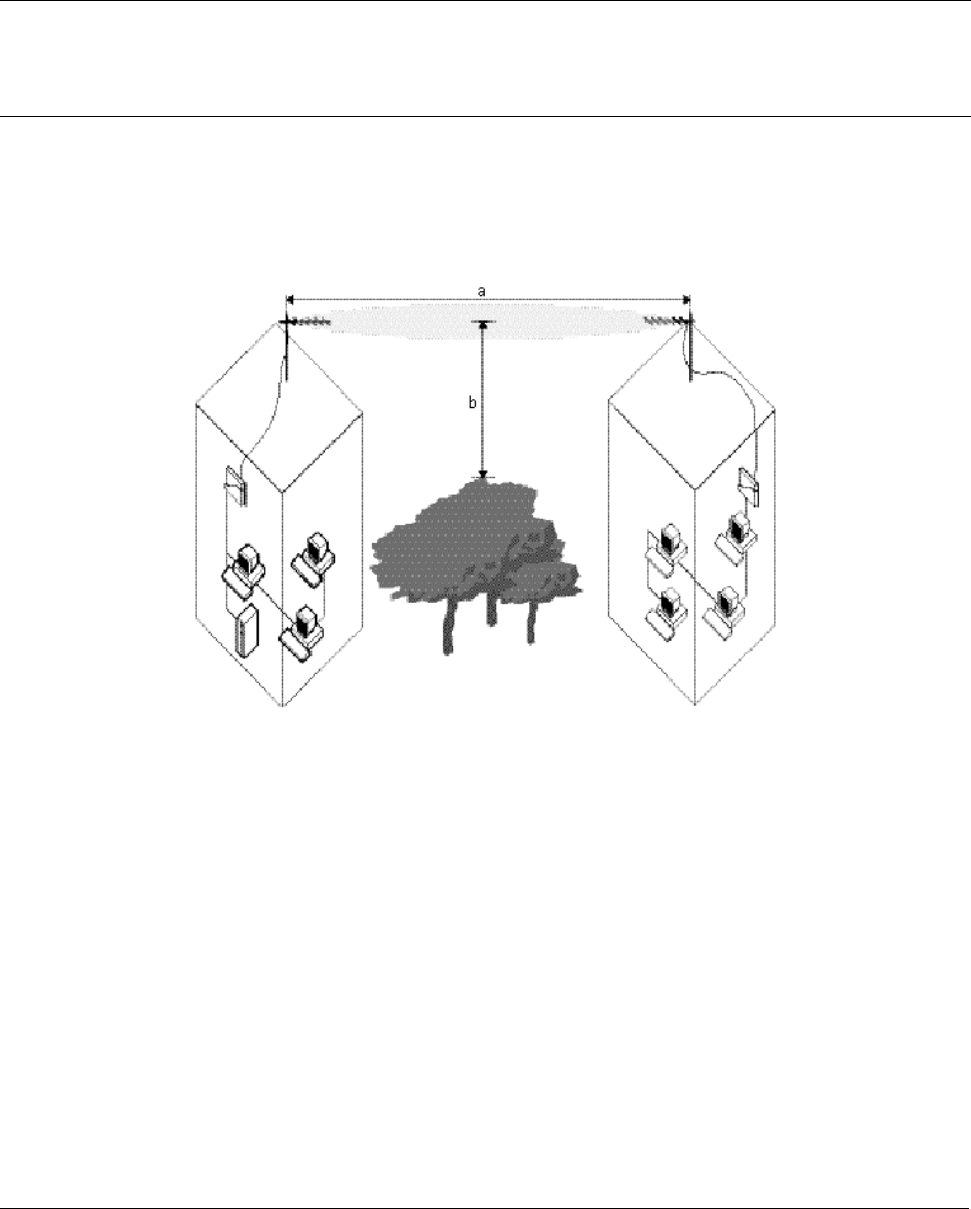
In Figure 5, you see two variables that determine the shape of the antenna beam, also referred to as Fresnel
Zone:
▪ The distance between the antennas (a)
▪ The clearance required for optimal performance (b), where clearance should be interpreted as:
º Vertical clearance above the ground and the highest buildings or objects in the signal path
º Horizontal clearance from neighboring buildings and objects in the signal path.
For optimal range and throughput performance, you must ensure that your antenna installation provides
maximum clearance in both horizontal and vertical direction.
Chapter 2. Determining Range and Clearance 18
CPN 65756 Issue Date: 01 August 2003

Tsunami MP.11a Antenna Installation Guide
Clearance should be interpreted as follows:
▪ In open areas without obstacles in the signal path, clearance is measured as height above the surface of
the earth. For example, if the antenna is mounted on the roof, this height includes the height of the
building plus the height of the mast above the rooftop.
▪ In areas with obstacles in the signal path between the two antennas, clearance should be measured as
height above the highest obstacle in the signal path.
▪ In dense urban areas, the clearance should be measured as height above the highest rooftop or any
other obstacles in the signal path between the two antennas.
For situations in which local authorities, the proprietor of the premises, or other factors do not let you set up
an antenna mast that lets you meet the listed clearance requirements, you may be unable to achieve a full
line-of-sight clearance. At the same time, however, when the distance that your wireless outdoor installation
must cover is less than the listed maximum range, you may not even need full clearance,.
To determine the effect of insufficient signal path clearance, you must determine the Clearance Factor as
described below, and calculate its effect on the range for your antenna installation using the formula
described in “Determining the Outdoor Range” on page 16.
▪ If the clearance for your antenna installation is equal to or better than the minimum clearance
requirement, the Clearance Factor for your installation is 100%.
▪ If your actual clearance is less than the minimum clearance, use the diagram depicted in the following
figure to determine the actual range that applies in your situation.
Note: The Clearance Factor Diagram should be used as a rule-of-thumb for estimating the probable range
in case the clearance requirements are not fully met. In real life, using FCC approved products, you
will also find it almost impossible to achieve the level of clearance for maximum range.
Figure 6. Clearance Factor Diagram
Chapter 2. Determining Range and Clearance 19
CPN 65756 Issue Date: 01 August 2003

Tsunami MP.11a Antenna Installation Guide
CALCULATIONS
Availability of the microwave path is a prediction of the percent of time that the link operates without
producing an excessive bit error rate (BER) due to multipath fading. In the absence of direct interference,
availability is affected by the following:
▪ Path length
▪ Fade margin
▪ Frequency
▪ Terrain (smooth, average, mountainous)
▪ Climate (dry, temperate, humid)
Depending upon the type of information carried over the link and the overall network design redundancy, you
may want to design for a specific availability rate. For example, if the data or voice traffic carried by the radio
is critical, the link can be designed for a very high availability rate (for example, 99.999% or 5.3 minutes of
predicted outage per year).
Availability can be improved by increasing the fade margin either by making the path shorter or by using the
higher gain antennas in conjunction with lower loss transmission line (using a higher quality transmission
line, shortening the length, or both).
Calculating Received Signal Level and Link Budget
Use the following formula to estimate the received signal level (RSL):
RSL (dBm) = Pout - L1+ G1 + G2 - L2 - Lp
where:
Pout is the transmitter output power (in dBm)
L1 is the total loss of all transmission elements between the antenna and the RF Unit on one
side of the link (in dB)
G1 is the gain of the antenna on one side of the link (in dB)
G2 is the gain of the antenna on the opposite side of the link (in dB)
L2 is the total loss of all transmission elements between the antenna and the RF Unit on the
opposite side of the link (in dB)
Lp is the Path loss, defined by:Lp (dB) = 96.6 + 20 log10F + 20 log10D
where:
F is the Frequency of the radio system in GHz (5.8 in the case of this model)
D is the Distance of the path in miles
See the following figure for a visual representation of the elements of this equation.
Chapter 2. Determining Range and Clearance 20
CPN 65756 Issue Date: 01 August 2003

Tsunami MP.11a Antenna Installation Guide
Procedure:
1. Start with the transmit power and the number of the channel to be used. From the output power tables
(on page 23) find the dBm associated with this output power and channel.
2. Subtract the total loss of all transmission elements between the antenna and the radio on one side of the
link (dB). (See “Minimum Antenna Cable Loss in 5 GHz Bands” on page 24.)
3. Add the dBi of the antenna you will be using. The total is the EIRP (equivalent isotropically radiated
power).
4. Determine your link budget from the Distance and Path Loss table, For example, if the distance between
the two radios is approximately 5 km, the link budget would be 121. (Note that this is the value for 4.8
km, which is closest to the actual value.)
5. Add the gain of the antenna on the second side of the link.
6. Subtract the total loss of all transmission elements between the antenna and the radio on the second
side of the link. The result is the Received Signal Level (RSL).
7. From the Receiver Sensitivity in Table 2 on page 22, find the dBm value for the data rate used for the
link.
8. Add the “Minimum SNR for a Good Link” value of the data rate in use to the Receiver Sensitivity level.
9. Subtract this value from the Received Signal Level; this is the Fade Margin.
Chapter 2. Determining Range and Clearance 21
CPN 65756 Issue Date: 01 August 2003

Tsunami MP.11a Antenna Installation Guide
Notes:
▪ The RSL must be higher than the Receiver Sensitivity plus the minimum SNR for a good link. See Table
3 on page 23, to have a working link with no excessive errors. The amount of Fade Margin indicates the
reliability of the link; the more Fade Margin, the more reliable the link.
▪ The path loss must be smaller than the link budget minus the minimum required fade margin. The
maximum ranges cause the path loss plus the fade margin to be the same as the link budget.
The results of this link budget calculation are very important for determining any potential problems during
installation. If you have calculated the expected RSL, you can verify that it has been achieved during
installation and troubleshooting, if necessary.
In the USA and Canada, this model radio can be installed with any gain directional antennas, as there is no
Effective Isotropic Radiated Power (EIRP) limit for the application of these systems for fixed point-to-point
applications. In other countries, EIRP limits may apply.
In the case of EIRP limits, use the lesser of either (Pout - L1+ G1) or the EIRP limit within the previous
equation. You should check this equation in both directions to assure legal application.
An EIRP limit is the maximum RF energy that can be transmitted, as measured at the transmitting antenna,
and is usually determined by government regulations.
Table 2. Receiver Sensitivity and Minimum SNR for a Good Link
Normal Mode
(Mbps)
Receiver
Sensitivity
Minimum SNR for
a Good Link
Turbo Mode*
(Mbps)
Receiver
Sensitivity
Minimum SNR for
a Good Link
54 - 69 dBm 21 108 - 66 dBm 21
48 - 73 dBm 20 96 - 70 dBm 20
36 - 77 dBm 16 72 - 74 dBm 16
24 - 81 dBm 12 48 - 78 dBm 12
18 - 84 dBm 9 36 - 81 dBm 9
12 - 86 dBm 7 24 - 83 dBm 7
9 - 87 dBm 5 18 - 84 dBm 5
6 - 88 dBm 4 12 - 85 dBm 4
* allowed in FCC regulatory domain only
The first Fresnel zone size is a list; Proxim’s recommendation is to keep at least 60-70% of this zone free. If
the clearance is lower than this percentage, the link budget and achieved fade margin are affected.
Clearances more than 100% of the Fresnel zone can cause reflections that are 180 degrees out of phase
and can cancel out the signal. The Fresnel zone works in both the horizontal and vertical paths.
Chapter 2. Determining Range and Clearance 22
CPN 65756 Issue Date: 01 August 2003

Tsunami MP.11a Antenna Installation Guide
Table 3. Output Power Table for FCC
Frequency Band Channels 54 Mbps 48 Mbps 36 Mbps 6-24 Mbps
5.25 – 5.35 GHz 52, 56, 60 14.5 15.5 17.5* 18.5*
5.25 – 5.35 GHz 64 12.5 12.5 12.5 12.5
5.745 – 5.850 GHz 149, 153 13.5 15.5 17.5 18.5
5.745 – 5.850 GHz 157, 161 13.5 15.5 17.5 17.5
5.745 – 5.850 GHz 165 12.5 15.5 17.5 17.5
* 17.4dBm is the FCC certified peak output power of Tsunami MP.11a product at 5.25-5.35GHz band
** 20.8dBm is the FCC certified peak output power of Tsunami MP.11a product at 5.725-5.850 GHz band
These power levels are the levels at the antenna connector of the MP.11, so where the MP.11 has a higher
output power than certified, the TPC needs to be used to reduce the output power.
Chapter 2. Determining Range and Clearance 23
CPN 65756 Issue Date: 01 August 2003

Tsunami MP.11a Antenna Installation Guide
Table 4. Output Power Table for ETSI
Frequency Band Channels 54 Mbps 48 Mbps 36 Mbps 6-24 Mbps
5.47 – 5.70 GHz 100, 104, 108, 112, 116, 120,
124, 128, 132, 136
14.5 15.5 17.5 18.5
Table 5. Examples of Antenna Cable Loss Required per Regulatory Domain and Antenna Type
Frequency Band
Antenna
Gain
TPC
Setting
Minimum Cable Loss for
Data up to 24 Mbps*
EIRP
Deployment
5.25-5.35 GHz
5.25-5.35 GHz
5.25-5.35 GHz
5.25-5.35 GHz
5.725-5.85 GHz
5.725-5.85 GHz
5.725-5.85 GHz
5.725-5.85 GHz
5.725-5.85 GHz
5.725-5.85 GHz
5.725-5.85 GHz
5.725-5.85 GHz
5.47-5.725 GHz
5.47-5.725 GHz
5.47-5.725 GHz
5.47-5.725 GHz
10
17
23
31
10
17
23
31
10
17
23
31
10
17
23
31
0
-6
-10
-10
0
0
-6
-10
0
0
0
0
0
-6
-10
-10
0
0
1.5
9.5
0
0
0
3.5
0
0
0
0
0
0
1.5
9.5
28.5
29.5
30
30
28.5
35.5
35.5
36
28.5
35.5
41.5
49.5
28.5
29.5
30
30
USA
USA
USA
USA
USA, PtMP
USA, PtMP
USA, PtMP
USA, PtMP
USA, PtP
USA, PtP
USA, PtP
USA, PtP
ETSI
ETSI
ETSI
ETSI
* Note that higher data rates use lower output power, so less cable loss is required to meet the maximum
EIRP limit.
Chapter 2. Determining Range and Clearance 24
CPN 65756 Issue Date: 01 August 2003
Tsunami MP.11a Antenna Installation Guide
Table 6. Distance and Link Budget
Reference Frequency: 5600 MHz Center Frequency for Europe
Link Budget
(dB)
Distance
(m)
Fresnel Zone
(m)
Link Budget
(dB)
Distance
(m)
Fresnel Zone
(m)
Link Budget
(dB)
Distance
(km)
Fresnel
Zone (m)
61 4.8 0.3 91 151 1.4 121 4.8 8.0
62 5.4 0.3 92 170 1.5 122 5.4 8.5
63 6.0 0.3 93 190 1.6 123 6.0 9.0
64 6.8 0.3 94 214 1.7 124 6.8 9.5
65 7.6 0.3 95 240 1.8 125 7.6 10.1
66 8.5 0.3 96 269 1.9 126 8.5 10.7
67 9.5 0.4 97 302 2.0 127 9.5 11.3
68 11 0.4 98 339 2.1 128 10.7 12.0
69 12 0.4 99 380 2.3 129 12.0 12.7
70 13 0.4 100 426 2.4 130 13.5 13.4
71 15 0.5 101 478 2.5 131 15.1 14.2
72 17 0.5 102 537 2.7 132 17.0 15.1
73 19 0.5 103 602 2.8 133 19.0 16.0
74 21 0.5 104 676 3.0 134 21.4 16.9
75 24 0.6 105 758 3.2 135 24.0 17.9
76 27 0.6 106 850 3.4 136 26.9 19.0
77 30 0.6 107 954 3.6 137 30.2 20.1
78 34 0.7 108 1071 3.8 138 33.9 21.3
79 38 0.7 109 1201 4.0 139 38.0 22.6
80 43 0.8 110 1348 4.2 140 42.6 23.9
81 48 0.8 111 1512 4.5 141 47.8 25.3
82 54 0.8 112 1697 4.8 142 53.7 26.8
83 60 0.9 113 1904 5.0 143 60.2 28.4
84 68 1.0 114 2136 5.3 144 67.6 30.1
85 76 1.0 115 2397 5.7 145 75.8 31.9
86 85 1.1 116 2689 6.0 146 85.0 33.7
87 95 1.1 117 3018 6.4 147 95.4 35.7
88 107 1.2 118 3386 6.7 148 107.1 37.9
89 120 1.3 119 3799 7.1 149 120.1 40.1
90 135 1.3 120 4263 7.6 150 134.8 42.5
The distance is based upon the assumption that 60% of the 1st Fresnel is clear.
Chapter 2. Determining Range and Clearance 25
CPN 65756 Issue Date: 01 August 2003

Tsunami MP.11a Antenna Installation Guide
Chapter 3. Installing the Antenna
PLANNING ANTENNA INSTALLATION
Plan the day for your outdoor antenna installation carefully. Do not install the antenna in wet or windy
conditions, during a thunderstorm, or when the area in which the equipment is to be installed is covered with
ice or snow.
The grounding system for the antenna mast, Tsunami MP.11a hardware, and surge arrestor should be
installed before the cable from the antenna is connected to the surge arrestor. This protects your system
against lightning strikes during installation.
Familiarize yourself with the antenna and the antenna-specific mounting instructions prior to climbing any
roof or ladder. Installing and testing all equipment before beginning the actual rooftop installation will help
you to determine whether all required equipment and items are available and are functioning properly.
To verify the equipment prior to installation, you may need to follow the guidelines as described in the
documentation that comes with the Tsunami MP.11a first.
SAFETY PRECAUTIONS
Read this section carefully before beginning the installation. All of the following requirements should be
satisfied prior to starting installation of your outdoor antennas.
DANGER!
The Tsunami outdoor antennas are intended for mounting on a roof, or on the side of a building.
Installation shall not be attempted by someone who is not trained or experienced in this type of work.
The antenna has to be installed by a suitably trained professional installation technician. The site
prerequisites have to be checked by a person familiar with the national electrical code, and other
regulations governing this type of installation.
Outdoor antennas and antenna cables are electrical conductors. Transients or electrostatic
discharges that may occur at the antenna (for example a lightning strike during thunderstorms) may
damage your electronic equipment and cause personal injury or death to persons touching the
exposed metal connectors of the antenna cable.
When installing, disconnecting or replacing one of the cabling components, you must ensure at all
times that each exposed metal connectors of the antenna cabling system will be grounded locally
during the work.
Do not install this antenna where there is any possibility of contact with high-voltage arc-over from
power cables or service drops to buildings. The antenna, supporting mast or tower must not be close
to any power lines during installation, removal or in the event of part of the system should
accidentally fail. Apply a ‘Danger’ label to a plainly visible area of the antenna support structure.
Do not climb rooftops in wet or windy conditions, during a thunderstorm or when the area where the
equipment will be installed is covered with ice or snow.
Do not touch antennas, surge arrestors and antenna cables during a thunderstorm.
The location where you will install the antenna(s) must be at a safe distance from power lines or
telephone lines. The safe distance should be at least twice the height of the antenna mast plus the
height of the antenna.
Chapter 3. Installing the Antenna 26
CPN 65756 Issue Date: 01 August 2003

Tsunami MP.11a Antenna Installation Guide
Antennas shall be mounted in such a manner to minimize the potential for human contact during
normal operation. In order to avoid the possibility of exceeding the FCC radio frequency exposure
limits, human proximity to the antenna shall not be less than 2 meters (6 feet) during normal
operation.
The low-loss antenna cable that will connect the antenna with the surge arrestor must be at least 1 m
(3 ft) away from any high voltage or high current cable.
Check whether the antenna mast and its guy wires or wall bracket are positioned correctly and
secured properly to the roof or wall(s).
Check whether the grounding system for the antenna mast, the Tsunami MP.11a hardware and surge
arrestor have been installed. The grounding system must comply with the requirements as described
in “Grounding System.”
Always consult a qualified electrician if you are in doubt as to whether the antenna mast, the surge
arrestor and Tsunami MP.11a hardware are properly grounded.
The antenna cable between the antenna and the surge arrestor must be grounded at all times. If the
cable is disconnected at one end for some reason (for example, to replace the surge arrestor) then
you must ensure that the exposed metal connector of the cable is grounded locally during the work.
INSTALLATION OVERVIEW
The installation process can be summarized in the following steps:
1. Verify that the support structure for the antenna has been connected to the grounding system. If this is
not the case, you should do so now.
2. Connect the exposed metal connectors of the low-loss antenna cable to the grounding system.
3. Mount the antenna to the support structure, following the guidelines as described for your antenna.
4. Connect the antenna cable to the antenna.
5. Route the antenna cable to the surge arrestor that has been installed indoors.
6. Connect the antenna cable to the surge arrestor.
7. Attach the surge arrestor to the N-type male connector pigtail hanging from the cable opening in the
Tsunami MP.11.
8. Run the Link Test diagnostics of the management tools that come with the Tsunami MP.11a to aim the
antenna and verify optimal placement.
9. Once the antenna is correctly positioned, and you have verified the installation works properly, secure all
cables and use weatherproofing tape to seal all outdoor connectors.
Note: When you must remove or relocate the antenna, follow the Safety Precautions at the beginning of
this chapter and follow the steps listed above in exactly the reverse order.
Chapter 3. Installing the Antenna 27
CPN 65756 Issue Date: 01 August 2003

Tsunami MP.11a Antenna Installation Guide
MOUNTING THE ANTENNA
Proxim Corporation offers multiple antennas to set up a wireless link. As the mounting procedures for the
various antennas differ from one another, consult the documentation you received from the antenna
manufacturer for mounting procedures.
When mounting multiple antennas on a single mast, use the following methods to minimize the influence of
cross-talk interference between the antennas:
▪ Place your antennas as far apart as you can.
▪ Alternate the mounting of directional antennas for vertical and horizontal polarization.
Connecting the Antenna Cable
Once the antenna is properly installed, you can connect the antenna to the Base Station or Subscriber Unit
by way of the surge arrestor:
1. Connect the antenna cable to the antenna.
2. Secure the antenna cable to the mast so that the cable connectors do not support the full weight of the
cable.
3. Connect the opposite end of the antenna cable to the surge arrestor.
CAUTION! To avoid damage to the antenna cable and connectors, refrain from using tools to
tighten the cable connectors.
4. Prior to securing the cable along its complete length, run the Link Test diagnostics of the management
tools that comes with Tsunami MP.11a to analyze wireless performance and optimal placement of the
outdoor antenna. How to use this tools is described in the documentation that comes with the Tsunami
MP.11a or can be from the Proxim website at http://www.expressresponse.com/proxim02/.
5. If required, adjust the direction of the antenna.
6. Once the installation has been fully tested, tighten the nuts of the antenna to “lock” the antenna into its
position.
CAUTION! Avoid over-tightening of the connector, and nuts and screws used to mount the
antenna, to prevent damage to your Tsunami MP.11a hardware.
7. Secure the cable along its complete length with cable ties or electrical tape to relieve strain on the
antenna connector properly. No part of the cable should be allowed to hang free. This is especially
important for those parts that are routed outside the building.
8. Proceed as described in the next section to weatherproof all outdoor coax connectors.
Chapter 3. Installing the Antenna 28
CPN 65756 Issue Date: 01 August 2003
Tsunami MP.11a Antenna Installation Guide
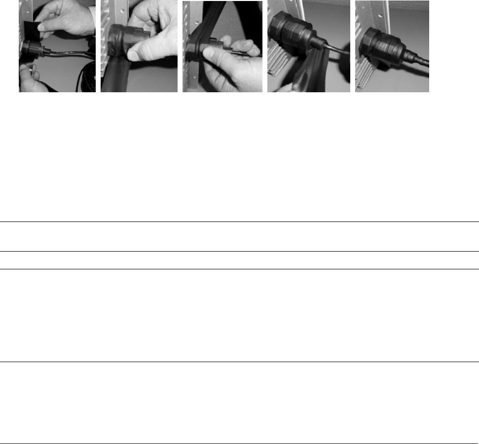
Sealing the Cable Connectors
Most problems associated with wireless outdoor installations are related to degrading performance due to
corrosion of the antenna cable and cable connectors. To avoid this type of problem, you must always seal
the cable connectors that are located outdoors using the weatherproofing tape provided.
You are advised to seal the connectors only after you have verified optimal alignment of the antennas using
the Link Test as described in the documentation that comes with the Tsunami MP.11. Doing so lets you
adjust antenna placement and cable routing without removing the tape.
1. Prepare the cable and connectors so that they are free from dust, dirt and grease.
2. Attach the tip of the weatherproofing tape to the cable just above the connector. Holding the tape in its
position, now stretch the tape and wind it half-overlapped around the cable and connectors to form a
void-free joint. The degree of stretch may vary in different sections of the joint, as long as the overlaps
accomplish a void-free application.
3. To protect the weatherproofing stretch tape from the effects of Ultra-Violet (UV) radiation (for example,
from direct sunlight), you should protect the joint with two half-overlapped layers of any vinyl plastic
electrical tape. Alternatively, you can apply silicone sealer to protect the weatherproofing tape from
sunlight, rain and other weather conditions.
Grounding System
Direct grounding of the antenna mast, Tsunami MP.11a hardware and surge arrestor is very important.
Note: A safety grounding system is necessary to protect your Tsunami MP.11a hardware from lightning
strikes and the build-up of static electricity.
WARNING! The antenna mast, Tsunami MP.11a hardware and surge arrestor must be connected to
the same ground, using an equi-potential bonding conductor.
A good electrical connection should be made to one or more ground rods, using at
least a 10AWG ground wire and non-corrosive hardware. The grounding system must
comply with the National Electrical Code and safety standards that apply in your
country. Always check with a qualified electrician if you are in doubt whether your
Tsunami MP.11a hardware installation is properly grounded or not.
Chapter 3. Installing the Antenna 29
CPN 65756 Issue Date: 01 August 2003

Tsunami MP.11a Antenna Installation Guide
Antenna Alignment
For optimal performance of your wireless link, make sure the antennas are properly aligned (facing one
another “eye-to-eye”). To align the antennas:
▪ Use a pair of binoculars or a map of the area and a compass to point the antennas to one another.
▪ Use the Link Test option of the management tools that come with the Tsunami MP.11a to analyze the
radio link quality.
▪ The Link Test option lets you display the radio signal strength in relation to the noise in the signal path.
▪ If required, you can interactively optimize the antenna alignment with the Link Test, by making small
modifications in the antenna orientation.
▪ Alternatively, consult a professional Antenna Installation Service to optimize the antenna alignment.
Omni-directional antennas are characterized by a wide radiation pattern. Therefore, alignment of this type of
antennas is less critical than alignment of directional antennas.
Antenna Polarization
Tsunami outdoor antennas are standard mounted for vertical polarization.
In some cases, you might consider mounting the antenna for horizontal polarization. For example, to
minimize the influence of cross-talk between antennas when:
▪ You plan to mount multiple directional antennas to the same mast.
▪ Your wireless link receives interference from a vertically polarized neighboring installation.
Mounting for horizontal polarization is not supported for omni-directional grid antennas.
Note: For optimal wireless link performance, you must always verify that the antenna polarization on both
ends of the wireless link is the same. Consult the corresponding instruction appendixes for changing
the antenna polarization.
Antenna Cable Routing
The antenna cable must be routed and fixed in such a way that installation technicians have a clear passage
area. All connectors that are located outdoors must have a weatherproof seal. You are advised to seal
connectors only after you have completed the final radio tests.
BEFORE CLIMBING THE ROOF...
Before you start installing, check whether you have all the required components to set up an outdoor
wireless link. For each side of a wireless outdoor wireless link you need:
▪ One or two low-loss antenna cables
▪ A female-female converter N-connector in case you want to use two antenna cables
▪ Tools and material to mount the antenna
▪ Tape or wraps to attach the antenna cable, for example to the mast
▪ Grounding material such as cable and connector
If an item is missing or damaged during shipment, inform your supplier.
Chapter 3. Installing the Antenna 30
CPN 65756 Issue Date: 01 August 2003

Tsunami MP.11a Antenna Installation Guide
Appendix A. Outdoor Antenna Equipment
As described previously, Proxim Corporation offers different types of outdoor antennas and cable lengths for
your network design.
The directional antennas provide maximum range, but due to their narrow beamwidth, these antennas
require precise antenna alignment to achieve optimal performance. The higher the antenna gain, the more
precise the alignment should be.
Directional antennas are typically used to connect:
▪ A Base Station Unit and a Subscriber Unit in a point-to-point link
▪ A Subscriber Unit in a point-to-multipoint network
The omni-directional antennas have, by nature, an omni-directional azimuth pattern that makes them easy to
install. There is also a gain beamwidth relation for omni-antennas: The higher the gain of the omni-antenna,
the narrower the vertical beamwidth. In a hilly terrain, a 7dBi omni-directional antenna can be a better
solution than the 10 dBi omni-directional antenna.
The 12 dBi wide-angle antenna is a good Base Station antenna for hilly terrain. It combines a wide opening
angle with relatively high gain. The mounting brackets allow tilting of the antenna. This antenna also is used
when the amount of traffic in a cell is too high for a single Base Station with an omni-directional antenna.
The wide-angle antenna allows dividing the cell into three sectors that each can be serviced by a Base
Station.
For beamwidth and gain characteristics of the various antennas, consult the appendixes of this manual,
which describe each antenna in more detail.
The length of the antenna cable also has an impact on the maximum range that can be achieved with the
antenna combination (see “Cable Factor” on page 17).
Depending upon local radio regulations in a number of countries that limit the maximum output power,
Proxim Corporation offers different outdoor antenna products in the various countries around the world.
Data Speed of the Wireless Link
By default, the radio of Tsunami MP.11a products transmits at the highest available transmit rate.
As data transmissions at lower speeds can travel larger distances than transmissions at the highest transmit
rate, the system lets you choose a lower data rate to increase the maximum range. For information about
customizing the transmit rate of your system, consult the Tsunami MP.11 and MP.11a Installation and
Management Guide (which is shipped with the Tsunami MP.11a).
Appendix A. Outdoor Antenna Equipment 31
CPN 65756 Issue Date: 01 August 2003

Tsunami MP.11a Antenna Installation Guide
ANTENNA LIST
Table 7. Antenna List
Type Manufacturer Model Number Frequency Range Gain
Omni Stella Doradus
Stella Doradus
Stella Doradus
Stella Doradus
52 2360
52 3360
58 2360
58 3360
5.200 – 5.300 MHz
5.200 – 5.300 MHz
5.700 – 5.900 MHz
5.700 – 5.900 MHz
10 dBi
13 dBi
10 dBi
13 dBi
Sector SmartAnt
Mars
R0320-057
MA-WC50-5X
5.15 – 5.875 MHz
5.15 – 5.875 MHz
11 dBi
17 dBi
Panel SmartAnt
SmartAnt
SmartAnt
SmartAnt
R0320-056
R0320-091
R0209-116
R0209-149
5.15 – 5.875 MHz
5.15 – 5.85 MHz
5.25 – 5.875 MHz
5.725 – 5.875 MHz
8 dBi
15 dBi
18 dBi
23 dBi
1-Foot Flat
Panel
Gabriel
Andrew
Mars
DFPD1-52
FPA5250D12-N
MA-WA-58-1X
5.25 – 5.85 MHz
5.25 – 5.85 MHz
5.725 – 5.85 MHz
23-23. dBi
23.6 dBi
23 dBi
2-Fo
Panel
ot Flat Gabriel
Andrew
RSI
DFPD2-52
FPA5250D24-N
A57A24-U
5.25 – 5.85 MHz
5.25 – 5.86 MHz
5.725 – 5.85 MHz
27.5-28.4 dBi
28.2 dBi
26.5 dBi
2-Foot
Parabolic
Gabriel
Gabriel
Gabriel
Radio Waves
Radio Waves
Andrew
Andrew
RSI
SSP2-52B
SSD2-52A
HSSP2-52
SP2-5.2
SPD2-5.2
P2F-52
PX2F-52
P-57C24
5.25 – 5.85 MHz
5.25 – 5.85 MHz
5.25 – 5.85 MHz
5.25 – 5.85 MHz
5.25 – 5.85 MHz
5.25 – 5.85 MHz
5.25 – 5.85 MHz
5.75 – 5.85 MHz
28.5 dBi
28.4 dBi
28.1 dBi
28.3 dBi
28.1 dBi
29.4 dBi
29.4 dBi
29 dBi
3-Fo
Parabolic
ot Radio Waves
Radio Waves
Andrew
Andrew
SP3-5.2
SPD3-5.2
P3F-52
PX3F-52
5.25 – 5.85 MHz
5.25 – 5.85 MHz
5.25 – 5.85 MHz
5.25 – 5.85 MHz
31.4 dBi
31.1 dBi
33.4 dBi
33.4 dBi
Notes:
▪ All Proxim radios require professional installation.
▪ Antennas with gain less than 8 dBi are not allowed.
▪ Antennas of other makes can be used with the HZB-A09UCF device (Tsunami MP.11a), but must be
of the same type, dimensions, and gain as those listed.
Appendix A. Outdoor Antenna Equipment 32
CPN 65756 Issue Date: 01 August 2003
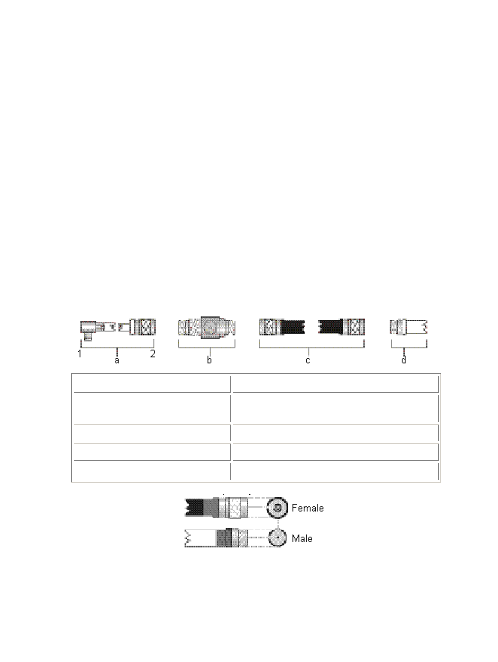
Tsunami MP.11a Antenna Installation Guide
Appendix B. Antenna Cabling System
OUTDOOR CABLING COMPONENTS
To connect your Tsunami MP.11a hardware to an outdoor antenna installation, you will need the following
cabling components:
▪ Surge arrestor
▪ Low-loss antenna cables
▪ One of the outdoor antennas described in Appendix C.
When purchasing new Tsunami MP.11a products, each of these components will be equipped with standard
N-type connectors.
When ordering separate components, for example as a spare part or replacement to previously purchased
Tsunami outdoor antenna equipment, carefully read the note on the following page to ensure that you order
components with an N-type connector that matches the other parts of your outdoor antenna cabling system.
SELECTING THE CORRECT CONNECTOR TYPE
All cabling components of the Tsunami outdoor antenna system come with standard-N type connectors as
depicted in the following table.
Table 8. Standard N-Type Connector Diagram
Cabling Component Standard-N Cabling Systems
a Pigtail attached to MP.11 1 Proprietary connector
2 Stand-N male
b Surge arrestor Reverse polarity-N female on both ends
c Low-loss cable Reverse Polarity-N male on both ends
d Outdoor antenna Reverse polarity-N female
Note that the gender of the connector is not determined by the connector’s thread, but by its center pin; a
solid center pin = male, a hollow pin = female.
Appendix B. Antenna Cabling System 33
CPN 65756 Issue Date: 01 August 2003
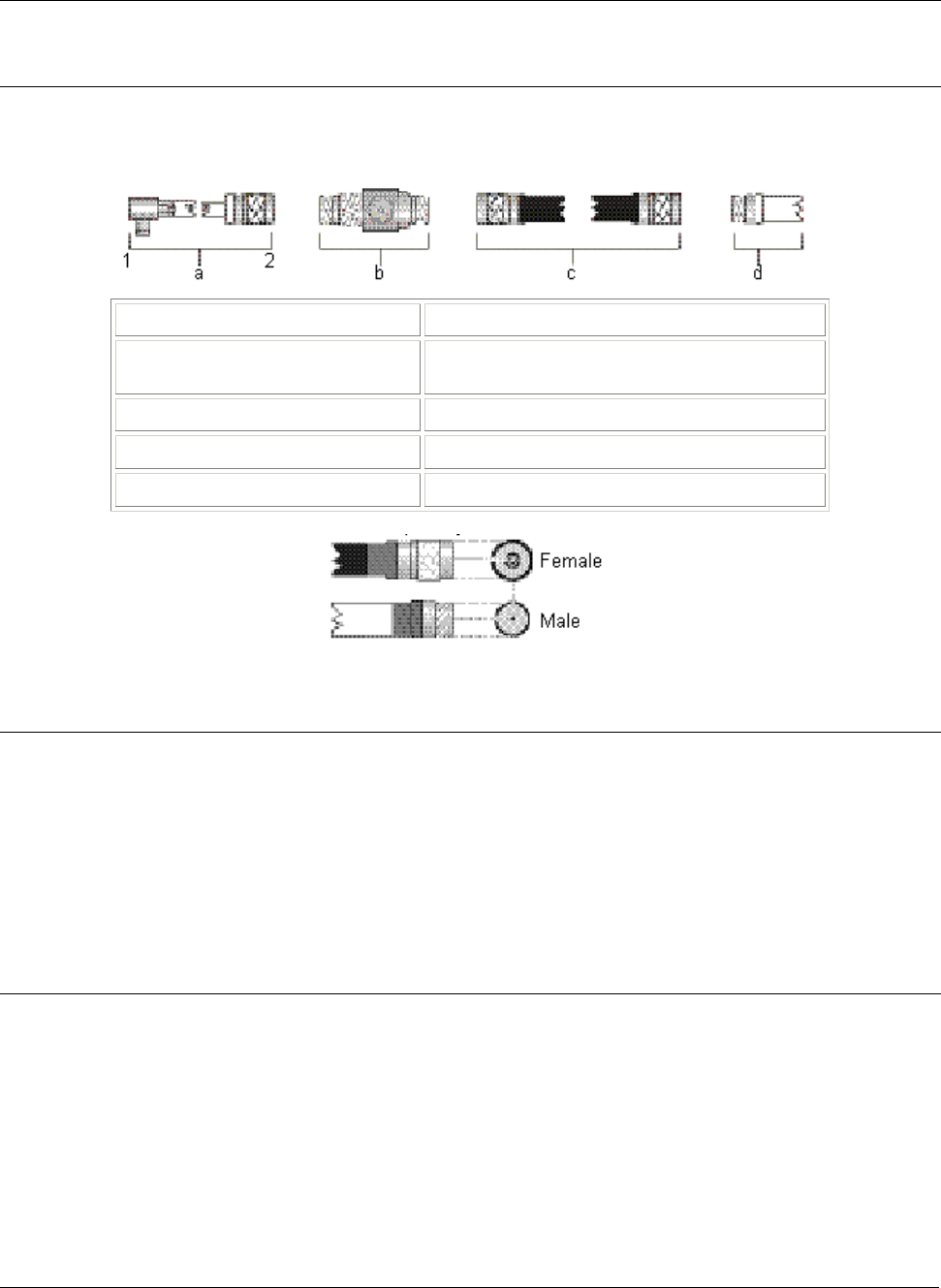
Tsunami MP.11a Antenna Installation Guide
Note: Previously marketed Tsunami outdoor antenna systems in FCC regulated countries (such as the
USA and Canada) were shipped with a different cabling system, identified by reverse polarity-N
connectors (depicted in the following table).
Table 9. Reverse Polarity-N Cabling Diagram
Cabling Component Reverse Polarity-N Cabling Systems
a Pigtail attached to MP.11 1 Proprietary connector
2 Reverse polarity-N male
b Surge arrestor Reverse polarity-N female on both ends
c Low-loss cable Reverse Polarity-N male on both ends
d Outdoor antenna Reverse polarity-N female
Note that the gender of the connector is not determined by the connector’s thread, but by its center pin; a
solid center pin = male, a hollow pin = female.
DANGER!
Outdoor antennas and antenna cables are electrical conductors. Transients or electrostatic
discharges that may occur at the antenna (for example a lightning strike during thunderstorms) may
damage your electronic equipment and cause personal injury or death to persons touching the
exposed metal connectors of the antenna cable.
To avoid damage and personal injury, the entire antenna cabling system must be grounded at all
times.
When installing, disconnecting or replacing one of the cabling components, you must ensure at all
times that each exposed metal connectors of the antenna cabling system will be grounded locally
during the work.
For example when mounting or replacing the surge arrestor:
1. First connect each of the connectors of the low-loss antenna cables to the grounding system.
2. Next connect the cable connector to the grounding system.
3. Finally connect the surge arrestor to the grounding system.
Before you proceed, verify that each of the items is properly grounded and that the ground will not
interrupted when disconnecting one of the antenna system components.
Appendix B. Antenna Cabling System 34
CPN 65756 Issue Date: 01 August 2003
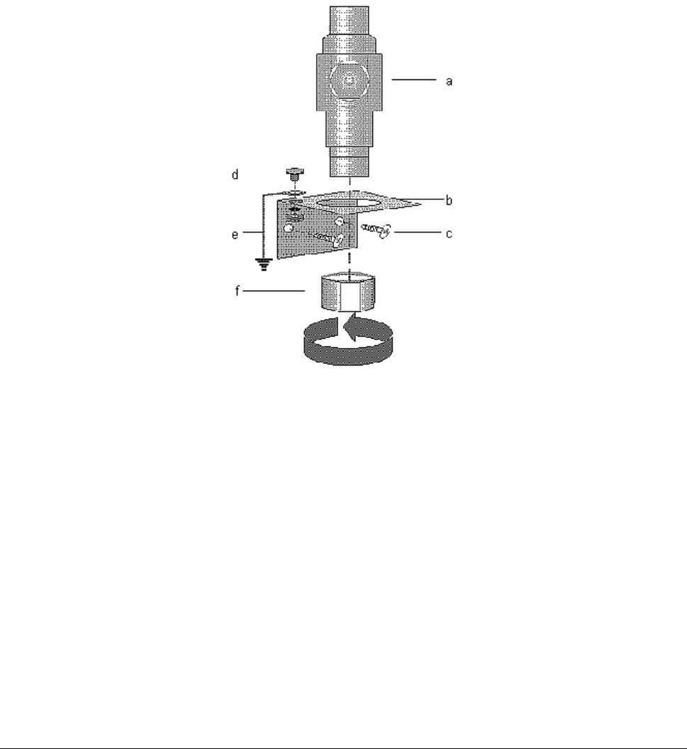
Tsunami MP.11a Antenna Installation Guide
Check with a qualified electrician if you are in doubt whether the surge arrestor and cable connectors are
properly grounded.
Only after you have verified that each of the items is properly grounded, replace the surge arrestor and
disconnect the cables from the grounding system in exactly the reverse order of the previous steps.
SURGE ARRESTOR
The surge arrestor (sometimes referred to as a Lightning Protector) can protect your sensitive outdoor router
equipment from high-voltage surges caused by discharges and transients at the antenna.
Figure 7. Surge Arrestor
To mount the surge arrestor:
1. Determine a suitable location for the bracket (item b) as described in “Chapter 1. Preparing for
Installation” on page 8.
2. Use the screws (item c) to attach the bracket to the wall.
3. Apply a ring-terminal to the ground wire. Use the bolt, lock-washer, and nut (item d) to connect the
ground wire (item e) to the mounting bracket.
4. The ring-terminal and ground wire are not included, but must be installed by a certified electrician familiar
with national electricity and safety codes, according to the instructions described in “Grounding System”
on page 16.
5. Insert the surge arrestor (item a) into the bracket as depicted in the preceding figure.
6. Use the hex-nut (item f) to secure the surge arrestor in its position. Ensure that the surge arrestor is
properly connected to the grounding system.
Appendix B. Antenna Cabling System 35
CPN 65756 Issue Date: 01 August 2003
Tsunami MP.11a Antenna Installation Guide
CAUTION!
To avoid damage to electronic equipment and your Tsunami MP.11a equipment always apply the
surge arrestor between the outdoor antenna installation and the Tsunami MP.11a hardware or other
computing device that is connected to the outdoor antennas.
Table 10. Specifications: Surge Arrestor
Mechanical
Size
Height 61 mm (2.4 in)
Diameter 23 x 27.5 mm (0.9 x 1.1 in)
Weight 133 g (4.7 oz.)
Connectors (1) Standard-N (female on both ends)
Operating Temperature -40°C (-40°F) to +85°C (+185° F)
Electrical
Frequency Range 6 GHz
Insertion Loss 0.4 dB
Surge Current 5 kA
Nominal Impedance 50 ohms
LOW-LOSS ANTENNA CABLE
The low-loss antenna cable is available in three standard lengths:
▪ 6 m (20 ft)
▪ 15 m (50 ft)
▪ 22 m (75 ft)
To ensure that you order the right cable length, determine the distance between the intended locations of the
Tsunami MP.11a hardware and outdoor antenna carefully.
Appendix B. Antenna Cabling System 36
CPN 65756 Issue Date: 01 August 2003
Tsunami MP.11a Antenna Installation Guide
Table 11. Specifications 6 m (20 ft) Antenna Cable
Mechanical
Length 6 meter (20 ft)
Connectors Standard-N (male on both ends)
Operating Temperature -40°C (-40°F) to +85°C (+185° F)
Diameter (1) 5 mm (0.2 in) 10 mm (0.4 in)
Weight 32.75 g/m (0.022 lbs/ft) 101.2 g/m (0.068 lbs/ft)
Bend Radius 50 mm (2 in) 100 mm (4 in)
Electrical
Insertion Loss at 5.8 GHz 0.80 dB/m 0.33 dB/m
(26.4 dB/100 ft) (10.8 dB/100 ft)
Total for this cable <6.0 dB < 3.0 dB
(1) Use of the 10 mm diameter version of this cable is subject to local radio
regulations. See “Appendix C. Certified Outdoor Solutions” for information about
whether you can use this cable in your country.
Table 12. Specifications 15 m (50 ft) Antenna Cable
Mechanical
Length 15 meter (50 ft)
Connectors (1) Standard-N (male on both ends)
Operating Temperature -40°C (-40°F) to +85°C (+185° F)
Diameter 10 mm (0.4 in)
Weight 101.2 g/m (0.068 lbs/ft)
Bend Radius 100 mm (4 in)
Electrical
Insertion Loss 0.33 dB/m (10.8 dB/100 ft) at 5.8 GHz
Total for this cable < 6.0 dB
Appendix B. Antenna Cabling System 37
CPN 65756 Issue Date: 01 August 2003
Tsunami MP.11a Antenna Installation Guide
Table 13. Specifications 22 m (75 ft) Antenna Cable
Mechanical
Length 22 m (75 ft)
Connectors (1) Standard-N (male on both ends)
Operating Temperature -40°C (-40°F) to +85°C (+185° F)
Diameter 10 mm (0.4 in)
Weight 101.2 g/m (0.068 lbs/ft)
Bend Radius 100 mm (4 in)
Electrical
Insertion Loss 0.33 dB/m (10.8 dB/100 ft) at 5.8 GHz
Total for this cable < 8.7 dB
Table 14. Specifications 15 m (50 ft) Extra Low Loss Antenna Cable
Mechanical
Length 15 meter (50 ft)
Connectors (1) Standard-N (male on both ends)
Operating Temperature -40°C (-40°F) to +85°C (+185° F)
Diameter 15 mm (0.59 in)
Weight 194.6 g/m (0.131 lbs/ft)
Bend Radius 150 mm (6 in)
Electrical
Insertion Loss 0.22 dB/m (7.3 dB/100 ft) at 5.8 GHz
Total for this cable < 4.0 dB
Appendix B. Antenna Cabling System 38
CPN 65756 Issue Date: 01 August 2003
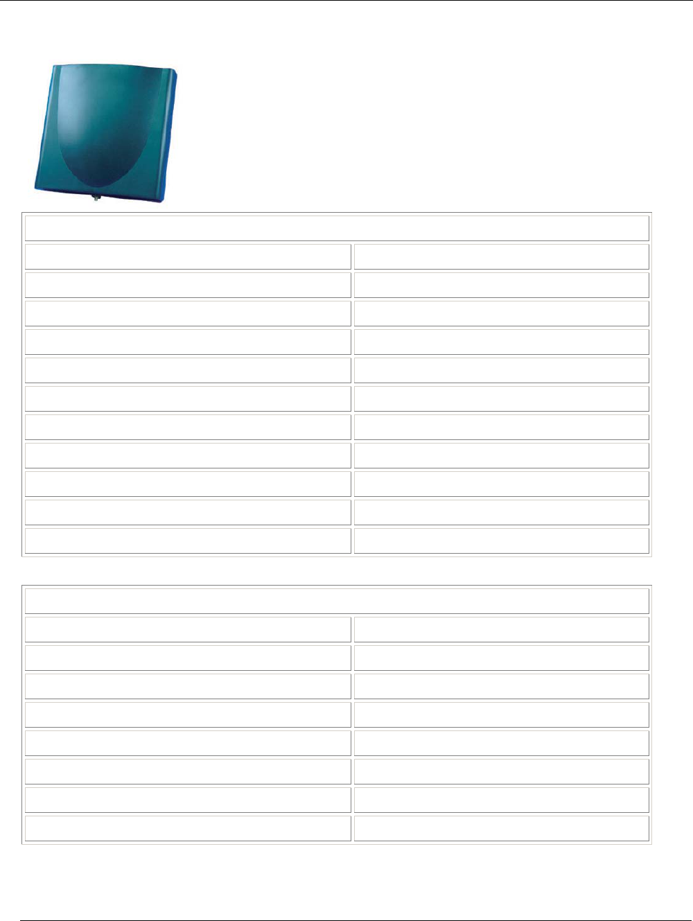
Tsunami MP.11a Antenna Installation Guide
Appendix C. Recommended Antennas
18 DBI HIGH GAIN DIRECTIONAL PANEL ANTENNA FOR 5.25 TO
5.875 GHZ
Pictured: SmartAnt antenna
Specifications
Electrical
Frequency Range 5.25-5825 MHz
VSWR 1.5: 1 maximum
Nominal Impedance 50 ohms
Gain 18 dBi
HPBW/horizontal 18 degrees
HPBW/vertical 18 degrees
Polarization Linear, vertical
Downtilt 0 degrees
Power handling 10W (cw)
Connector Standard N female
Front-to-back ratio 30 dB
Environmental and Mechanical
Wind Survival (per EIA-222-F at 100’ height) 216 km/hr
Temperature range -40 to +80 degrees C
Humidity 95% @ 25 degrees C
Lightning protection DC ground
Size 200 x 200 x 50 mm
Radome color Black
Radome material ABS, UV resistant
Weight 0.825 kgw
Appendix C. Recommended Antennas 39
CPN 65756 Issue Date: 01 August 2003
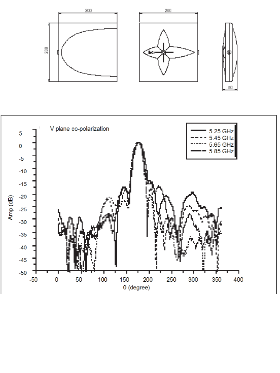
Tsunami MP.11a Antenna Installation Guide
Dimensions
Pattern
Appendix C. Recommended Antennas 40
CPN 65756 Issue Date: 01 August 2003
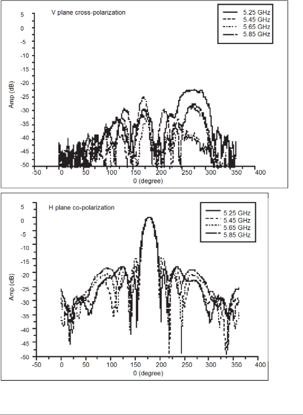
Tsunami MP.11a Antenna Installation Guide
Appendix C. Recommended Antennas 41
CPN 65756 Issue Date: 01 August 2003
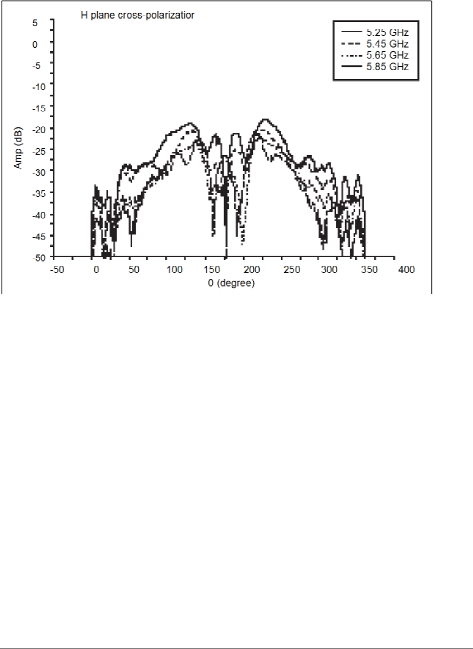
Tsunami MP.11a Antenna Installation Guide
Appendix C. Recommended Antennas 42
CPN 65756 Issue Date: 01 August 2003
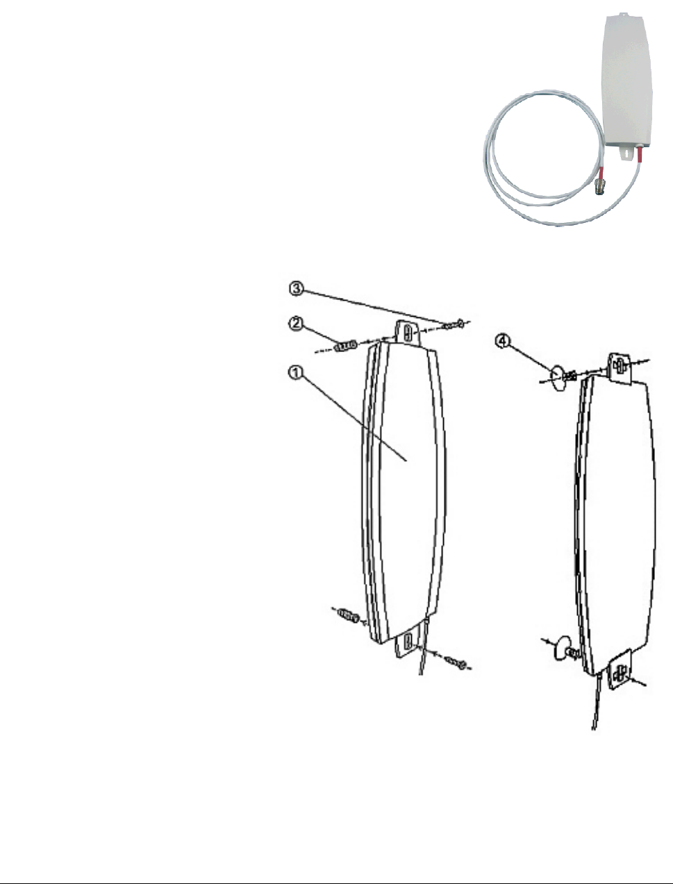
Tsunami MP.11a Antenna Installation Guide
15 DBI HIGH GAIN DIRECTIONAL PANEL ANTENNA FOR 5 GHZ
Pictured: SmartAnt antenna
General Description
This window antenna is a high-gain antenna for the 5 GHz frequency
band. This antenna is typically used in combination with a Subscriber
Unit. The red heat-shrink tube at the antenna connector of this antenna
matches the red heat-shrink tube at the MP.11a antenna connector to
easily locate and distinguish the 5 GHz antenna components from their
look-alikes operating at 2.4 GHz which do not have red heat-shrink tube.
Mounting Instructions
Package contents:
▪ Antenna
(1) Antenna body
(2) plastic conical anchor
(3) screw
(4) window suction cup
▪ Extension Cable (3m)
▪ Mounting Kit
▪ Quick Installation Guide
Wall Mount for Outdoor/Indoor
Application
A. Insert the plastic wall plug (2)
into the wall
B. Insert the screw (3) into the plastic
wall plug through the antenna
mounting hole and tighten
Window Suction Mount for Indoor
Application
A. Insert the window suction cup
through the antenna mounting
hole.
B. Turn the suction cup one quarter to
lock it into position.
C. Press the window suction cup onto
the window glass.
Appendix C. Recommended Antennas 43
CPN 65756 Issue Date: 01 August 2003
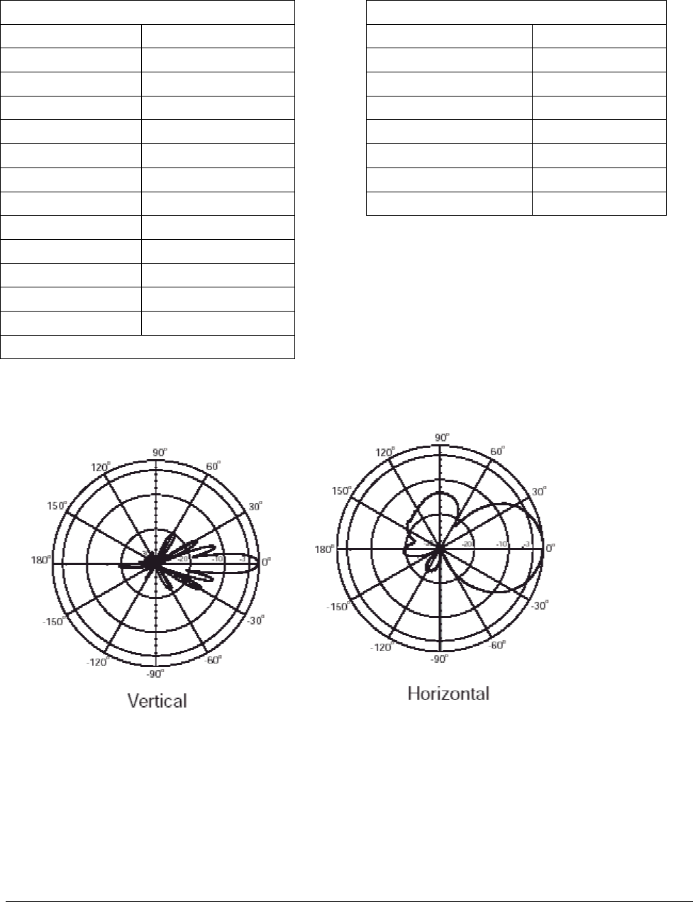
Tsunami MP.11a Antenna Installation Guide
Specifications
Electrical Environmental and Mechanical
Frequency range 5150 MHz – 5850 MHz Survival wind speed 180 km/hr
Gain* 15 dBi Temperature -40º C to +80º C
VSWR 2.0 : 1 Max. Humidity 95% @ 25º C
Polarization Linear, vertical Lightning Protection DC ground
HPBW / horizontal 45 degrees Radome color white
HPBW / vertical 10 degrees Radome material ABS, UV resistant
Front to back ratio 18 dB Weight 0.6 kgw
Downtilt 0 degrees Dimensions 330 x 93 x 21 mm
Power handling 20 W (cw)
Impedance 50 Ohms
Connector Standard N-female
Cable ULA-168; 200 cm
Cable loss 2 dB
*exclusive of cable loss
Pattern
Appendix C. Recommended Antennas 44
CPN 65756 Issue Date: 01 August 2003
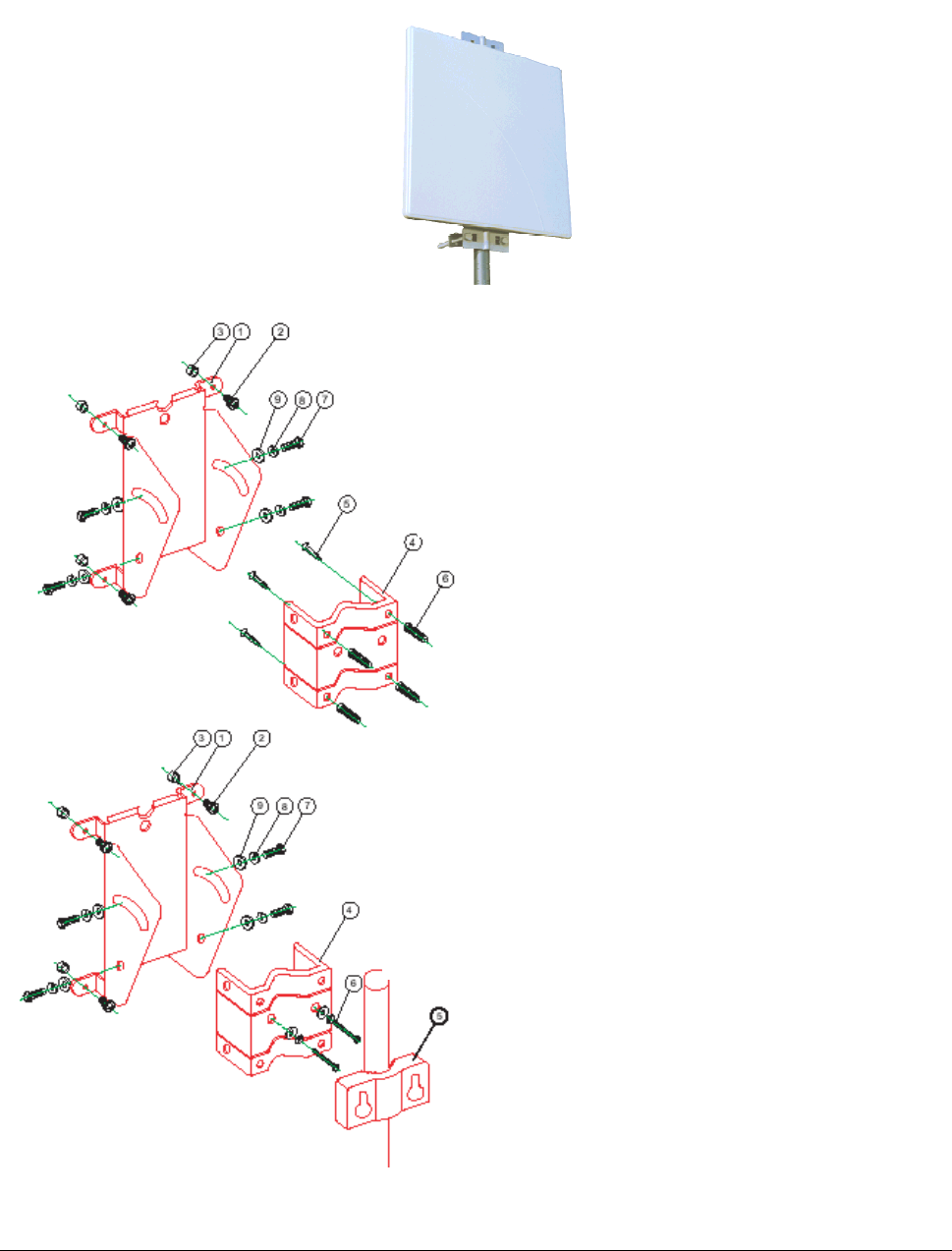
Tsunami MP.11a Antenna Installation Guide
23 DBI HIGH GAIN DIRECTIONAL PANEL ANTENNA FOR 5.8 GHZ
Pictured: SmartAnt antenna
Package Contents
▪ Antenna
▪ Extension Cable (50cm)
▪ Mounting Kit
▪ Surge Protector
▪ Water-proof tape
▪ Quick Installation Guide
Mounting
1. Mounting base, 1 PC
2. M4*8 screw+W+S/W-4 PCS
3. Space keeper – 4 pcs
4. M-shape mounting – 1 pc
5. ¾” screw – 4 pcs
6. Plastic wallplug – 4 pcs
7. M6*16 screw – 4 pcs
8. M6 S/W – 4 pcs
9. M6 W – 4 pcs
1. Mounting base, 1 PC
2. M4*8 screw+W+S/W-4 PCS
3. Space keeper – 4 pcs
4. M-shape mounting – 1 pc
5. Pole mount clip – 1 pc
6. M6*60 screw – 2 pcs
7. M6*16 screw – 4 pcs
8. M6 S/W – 4 pcs
9. M6 W – 4 pcs
Appendix C. Recommended Antennas 45
CPN 65756 Issue Date: 01 August 2003
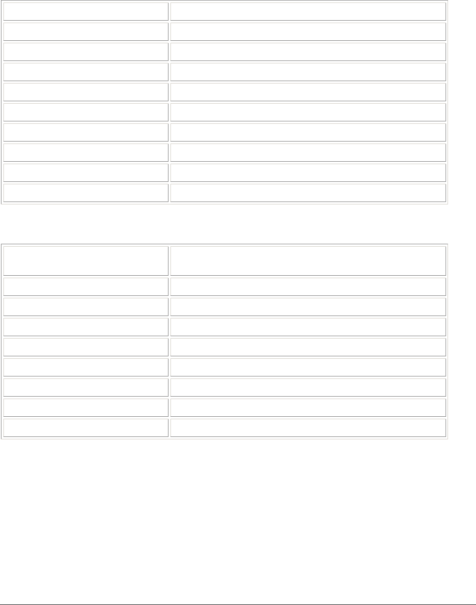
Tsunami MP.11a Antenna Installation Guide
Specifications
Electrical
Frequency Range 5725 - 5875 MHz
Nominal Impedance 50 ohms
Gain 23 dBi
Front-to-Back Ratio 40 dB
HPBW/vertical 9 degrees
HPBW/horizontal 9 degrees
Cross Polarization 25 dB
Power handling 20 W (cw)
Connector Standard N female
VSWR 1.5: 1 maximum
Environmental and Mechanical
Wind Survival (per EIA-222-F at
100’ height)
216 km/hr
Temperature range -40 to +80 degrees C
Humidity 95% @ 25 degrees C
Lightning protection DC ground
Size 360 x 360 x 16 mm
Weight 1.6 kgw
Radome material ABS, UV resistant
Housing material Powder-coating tron
Radome color white
Appendix C. Recommended Antennas 46
CPN 65756 Issue Date: 01 August 2003
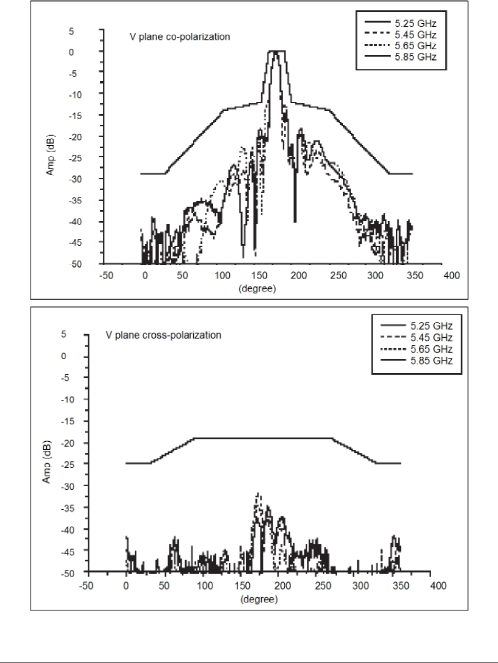
Tsunami MP.11a Antenna Installation Guide
Pattern
Appendix C. Recommended Antennas 47
CPN 65756 Issue Date: 01 August 2003
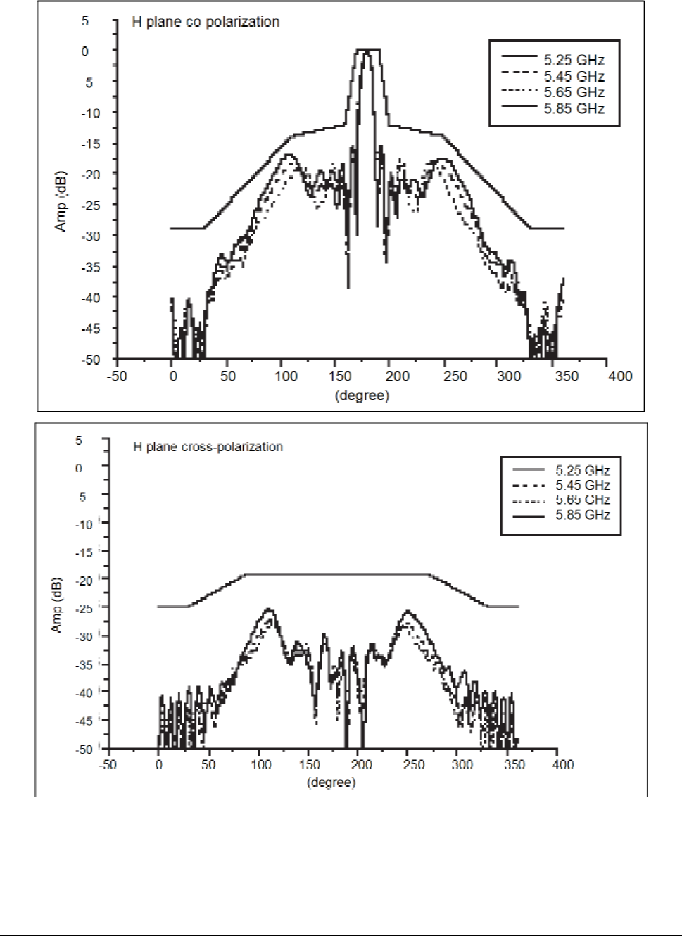
Tsunami MP.11a Antenna Installation Guide
Appendix C. Recommended Antennas 48
CPN 65756 Issue Date: 01 August 2003

Tsunami MP.11a Antenna Installation Guide
Appendix D. Certified Outdoor Solutions
INTRODUCTION
As radio regulations differ between the various countries world-wide, not all of the outdoor solutions
described in this Tsunami Outdoor Antenna Installation Guide may be allowed in the country where you plan
to install this equipment.
Local radio regulations or legislation may impose restrictions on the use of specific combinations of:
▪ Low-loss antenna cables and outdoor antennas.
▪ Radio channels selected at the Outdoor Routers that are connected to specific outdoor antennas.
Note: Basic rule for selecting a combination of cables and antennas is that no combination is allowed
unless explicitly approved in this Tsunami Outdoor Antenna Installation Guide. Therefore, always
use this Appendix in combination with “Chapter 2. Determining Range and Clearance” on page 16 of
this document to select the right type of antenna equipment and to inform your antenna installer and
LAN administrator about the impact of regulatory constraints on their job or activities.
SELECTING THE CORRECT CABLES
To comply with local radio regulations, the MP.11a Base Station and Subscriber units have a selectable
radio power output level. It can be selected through the TPC (Transmit Power Control) parameter in the user
Interface.
The low-loss antenna cables are available in various lengths and diameters:
▪ 6 m (15 ft) with a diameter of 5 mm (0.2 in) (The cable-loss of this cable is equal to the loss of the 15 m
(50 ft) cable.)
▪ 6 m (15 ft) with a diameter of 10 mm (0.4 in)
▪ 15 m (50 ft) with a diameter of 15 mm (0.6 in)
▪ 15 m (50 ft) with a diameter of 10 mm (0.4 in)
▪ 22 m (75 ft) with a diameter of 10 mm (0.4 in)
When you order the Tsunami MP.11a antenna equipment, make sure that you order cables that comply with
the regulations that apply in your country. (See Table 5 on page 24 for the minimum required antenna cable
attenuation and corresponding TPC setting.) In case of doubt, consult the Proxim Corporation Sales office
for more information.
Appendix D. Certified Outdoor Solutions 49
CPN 65756 Issue Date: 01 August 2003
Tsunami MP.11a Antenna Installation Guide
Appendix E. Channel Frequencies
The following table shows MP.11 (802.11b) channel allocations that vary from country to country. Values
listed in bold indicate default channels and frequencies.
Channel ID FCC/World (GHz) ETSI (GHz) France (GHz) Japan (GHz)
1 2.412 2.412 -- 2.412
2 2.417 2.417 -- 2.417
3 (default in most countries) 2.422 2.422 -- 2.422
4 2.427 2.427 -- 2.427
5 2.432 2.432 -- 2.432
6 2.437 2.437 -- 2.437
7 2.442 2.442 -- 2.442
8 2.447 2.447 -- 2.447
9 2.452 2.452 -- 2.452
10 2.457 2.457 2.457 2.457
11 (default in France) 2.462 2.462 2.462 2.462
12 -- 2.467 2.467 2.467
13 -- 2.472 2.472 2.472
14 2.484
The following table shows MP.11a (802.11a) channel allocations that vary from country to country. Values
listed in bold indicate default channels and frequencies.
Channel ID FCC ETSI Turbo Mode Channels
56 5.280 ─ Channel ID FCC
60 5.300 ─ 1 5.290*
64 5.320 ─ 2 5.300
100 ─ 5.500 3 5.760
104 ─ 5.520 4 5.800
108 ─ 5.540
112 ─ 5.560
116 ─ 5.580
120 ─ 5.600
124 ─ 5.620
128 ─ 5.640
132 ─ 5.660
136 ─ 5.680
149 5.745 ─
153 5.765 ─
157 5.785 ─
161 5.805 ─
165 5.825 ─
* Turbo channel ID 1, 5.290 – The MP.11a firmware limits the upper limit of this channel to be below 12.13
dBm for release in the United States and Canada.
Appendix E. Channel Frequencies 50
CPN 65756 Issue Date: 01 August 2003

Tsunami MP.11a Antenna Installation Guide
Support and Warranty
TECHNICAL SUPPORT
If you encounter problems when installing or using this product, consult the Proxim Support website:
http://www.expressresponse.com/proxim02/ for:
▪ The latest software, user documentation and product updates
▪ The Frequently Asked Questions (FAQ)
Alternatively, contact your local authorized Tsunami MP.11a reseller for Technical Support.
Help us to help you by completing the problem report form and include it with your e-mail or fax when
contacting Technical Support. You can find the problem report form (report.txt) on the CD-ROM, and on the
support pages of the Proxim website.
Addresses of authorized Tsunami MP.11a resellers are listed in the “Contact & Ordering” section of the
Proxim website.
WARRANTY AND REPAIR
If it appears that your unit needs a repair or replacement, return the unit to your Dealer or Distributor in its
original packaging. When returning a defective product for Warranty, always include the following
documents:
▪ The Warranty Repair card (last page of this appendix)
▪ A copy of the invoice or proof of purchase
▪ Problem Report Form
Proxim Corporation extends a limited warranty from date of purchase of:
▪ Twelve (12) months for the Tsunami MP.11a hardware
▪ Twelve (12) months for the media on which the software is furnished and the reproduction of the
software on the media.
Upon proof-of-purchase Proxim Corporation shall, at its discretion, repair or replace the defective item at no
cost to the buyer.
Defective items shall be returned to the dealer or distributor:
▪ Freight prepaid.
▪ Accompanied by a copy of proof-of-purchase.
▪ Accompanied by a filled out Warranty and Repair card.
This warranty is contingent upon proper use in the application for which the products are intended and does
not cover products which have been modified without the seller’s approval or which have been subjected to
unusual physical or electrical demands or damaged in any way.
This Warranty constitutes the sole and exclusive remedy of any buyer or seller’s equipment and the sole and
exclusive liability of Proxim Corporation in connection with the products and is in lieu of all other warranties,
express, implied or statutory, including, but not limited to, any implied warranty of merchantability of fitness
for a particular use and all other obligations or liabilities of Proxim Corporation.
In no event will Proxim Corporation or any other party or person be liable to you or anyone else for any
damages, including lost profits, lost savings or other incidental or consequential damages, or inability to use
the software provided on the software media even if Proxim Corporation or the other party person has been
advised of the possibility of such damages.
Support and Warranty 51
CPN 65756 Issue Date: 01 August 2003

Tsunami MP.11a Antenna Installation Guide
TO BE FILLED OUT BY USER:
Product Description____________________________________________________________________
COMCODE (Product ID)________________________________________________________________
Serial Number________________________________________________________________________
Invoice Date (dd/mm/yyyy):______________________________________________________________
Name:______________________________________________________________________________
Title________________________________________________________________________________
Company ___________________________________________________________________________
Address ____________________________________________________________________________
City/State/Zip Code ___________________________________________________________________
Country ____________________________________________________________________________
Telephone __________________________________________________________________________
Fax ________________________________________________________________________________
TO BE FILLED OUT BY THE DEALER OR DISTRIBUTOR
Dealer Name ________________________________________________________________________
City/State/Zip Code ___________________________________________________________________
Country ____________________________________________________________________________
Telephone __________________________________________________________________________
Fax _______________________________________________________________________________
Warranty (Yes / No) __________________________________________________________________
Comment __________________________________________________________________________
Return Approval Reference ____________________________________________________________
Reported Problem Problem Description
Support and Warranty 52
CPN 65756 Issue Date: 01 August 2003