Proxim Wireless LYNX96 Direct Sequence Spread Spectrum Radio User Manual manual
Proxim Wireless Corporation Direct Sequence Spread Spectrum Radio manual
UserManual.wiki
>
Proxim Wireless
>
LYNX96 User Manual
manual
Navigation menu
Upload a User Manual
Namespaces
Wiki Guide
HTML
PDF
Info
Views
User Manual
Discussion / Help
Navigation


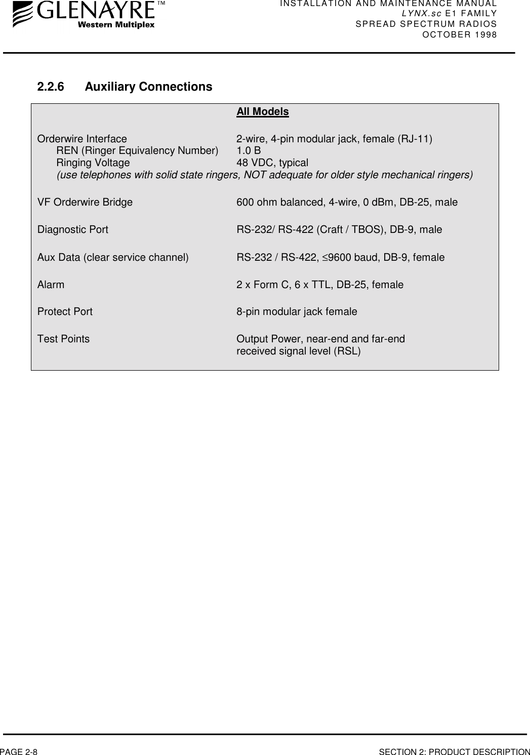
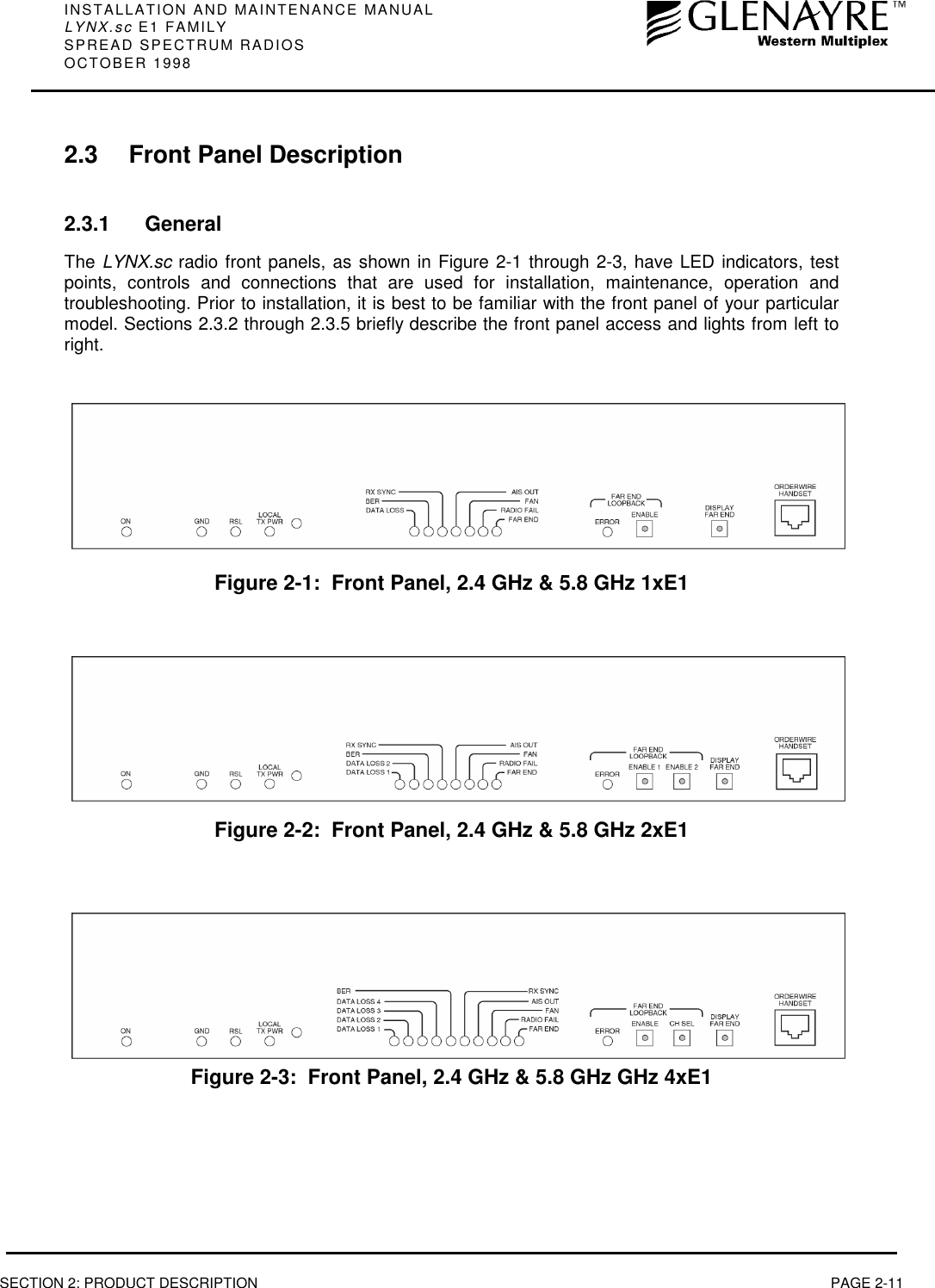
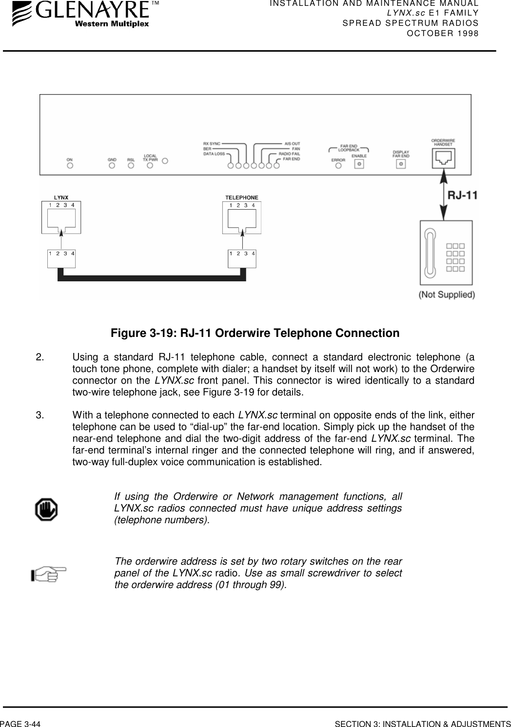
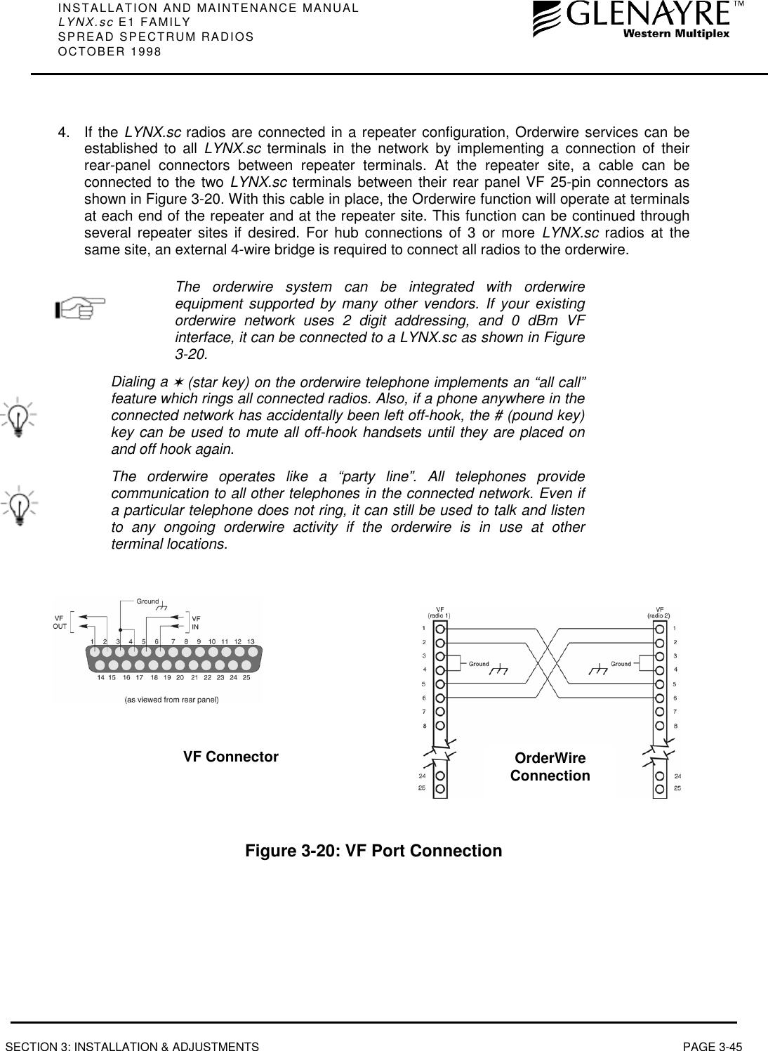
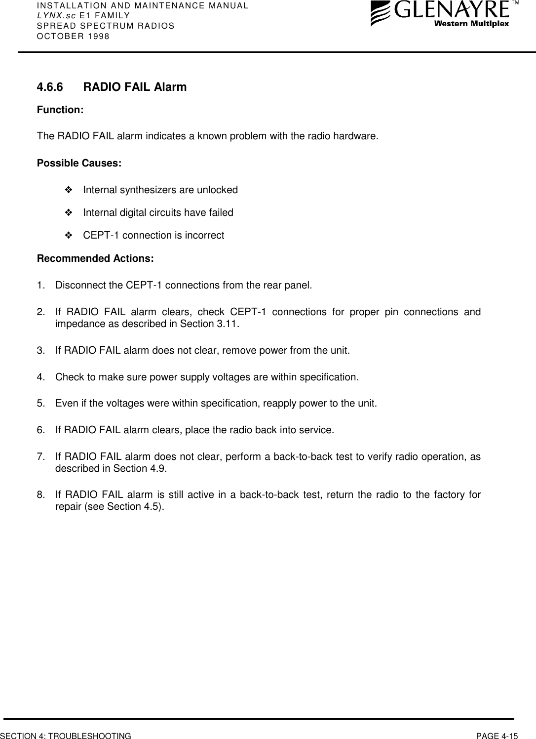
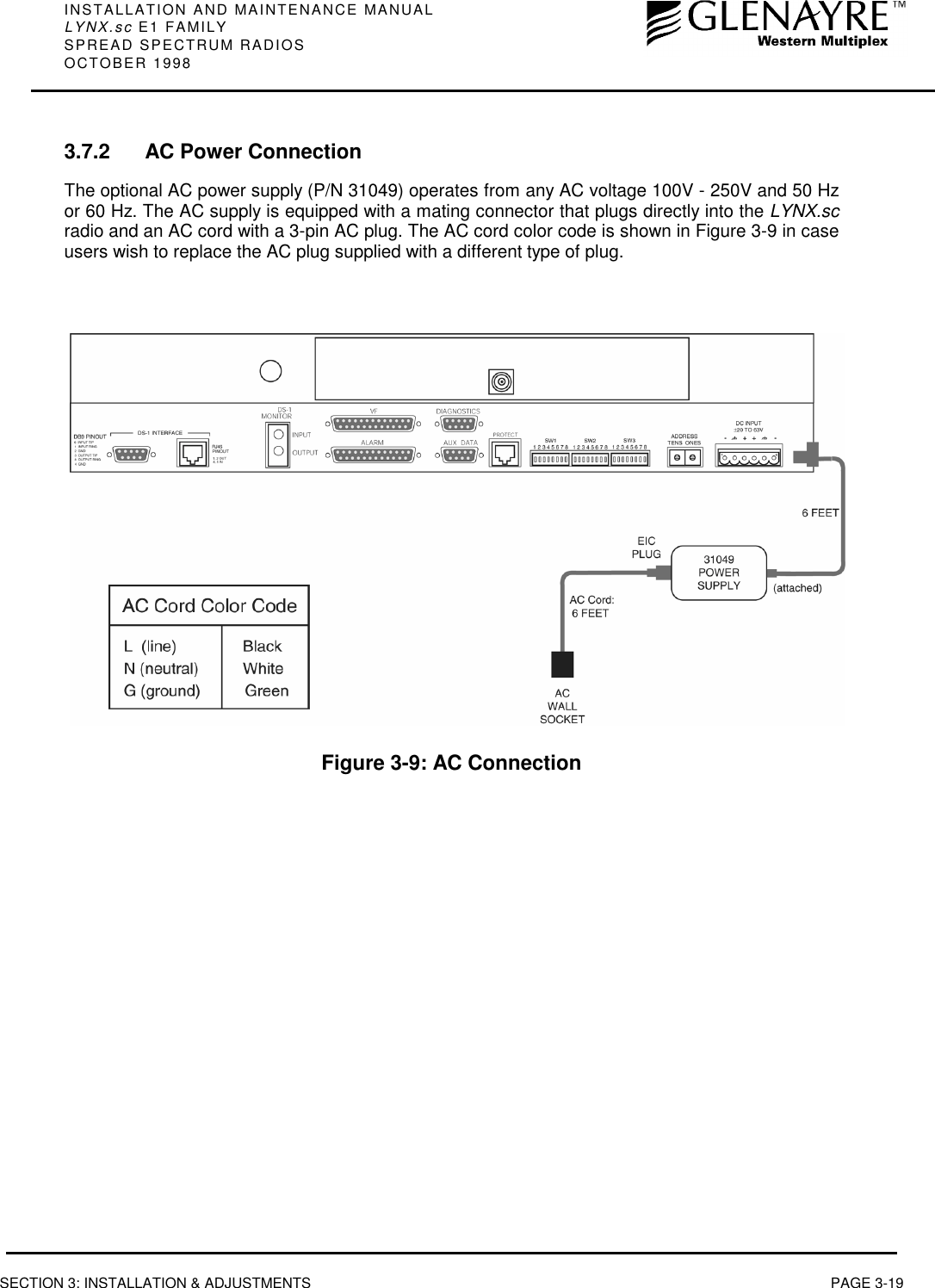
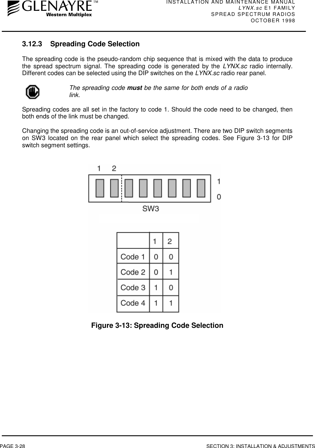
![INSTALLATION AND MAINTENANCE MANUALLYNX.sc E1 FAMILYSPREAD SPECTRUM RADIOSOCTOBER 1998SECTION 2: PRODUCT DESCRIPTION PAGE 2-152.3.5 ConnectionsORDERWIREThis connection is used to access the orderwire function. This is a facility for "telephone" styleservice from one radio to another. A standard electronic telephone [one with a handset and DTMF(push-button tone) dialing] plugs into this connector. The user can dial the orderwire address ofthe far-end radio (or any radio in the LYNX.sc network) to establish telephone communicationbetween sites. This communication does not interrupt or interfere with the other radiocommunications. The radio link must be operational to use this facility. The orderwire feature canbe very useful for installation, maintenance and troubleshooting.](https://usermanual.wiki/Proxim-Wireless/LYNX96/User-Guide-24828-Page-31.png)


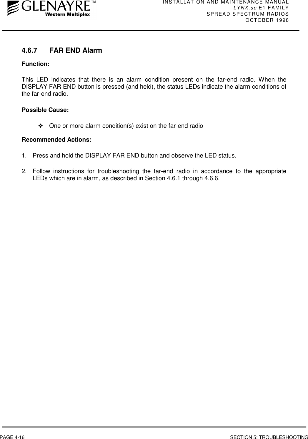
![INSTALLATION AND MAINTENANCE MANUALLYNX.sc E1 FAMILYSPREAD SPECTRUM RADIOSOCTOBER 1998SECTION 3: INSTALLATION & ADJUSTMENTS PAGE 3-53.3.3 RSL Calculation and Link BudgetThe received signal level (RSL) can be estimated using the following formula:RSL (dBm) = Pout - FL1+ G1 + G2 - FL2 - Lpwhere: Pout is the transmitter output power (in dBm)FL1 is the feeder loss of the transmit side (in dB)G1 is the gain of the transmit antenna (in dB)G2 is the gain of the receive antenna (in dB)FL2 is the feeder loss of the receive side (in dB)Lp is the Path loss, defined by:Lp (dB) = 96.6 + 20 log10F + 20 log10Dwhere: F = Frequency in GHz (2.4 or 5.8)D = Distance of path in milesThis link budget is very important for determining any potential problems during installation. If youhave calculated the expected RSL, you can see if it has been achieved during installation, andtroubleshoot if necessary.In the USA, 5.8 GHz models of the LYNX.sc may be installedwith any size directional antennas and operated at full power.The 2.4 GHz model may require power reduction where: Pout -FL1+ G1 is replaced by 30 - [(G1 - 6)/ 3] + FL1In some countries effective isotropic radiated power (EIRP)limits apply, such as +6 dBW (+36 dBm) in Canada. Outputpower may need to be reduced, and the above path planningequation changed such that: EIRP (dBm) = Pout + G1 - FL1](https://usermanual.wiki/Proxim-Wireless/LYNX96/User-Guide-24828-Page-45.png)


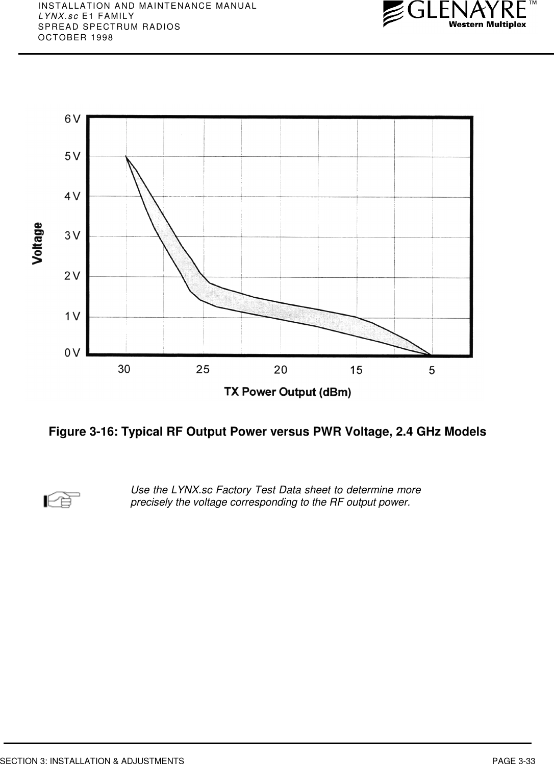
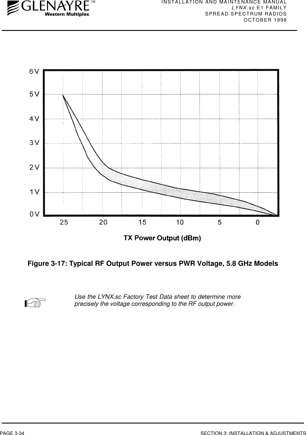
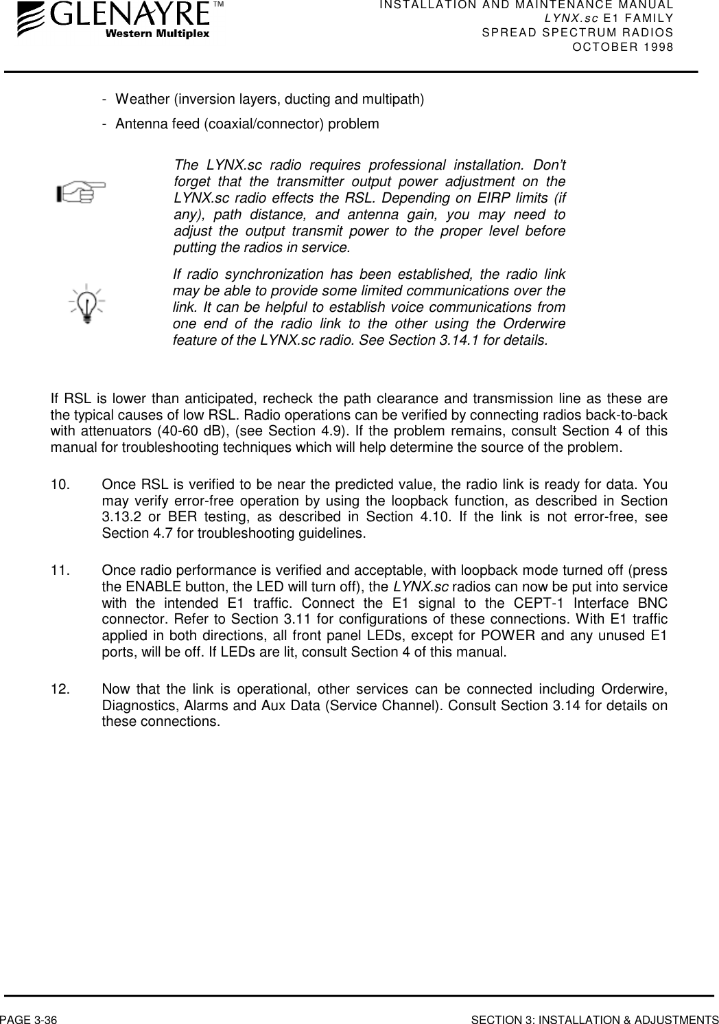
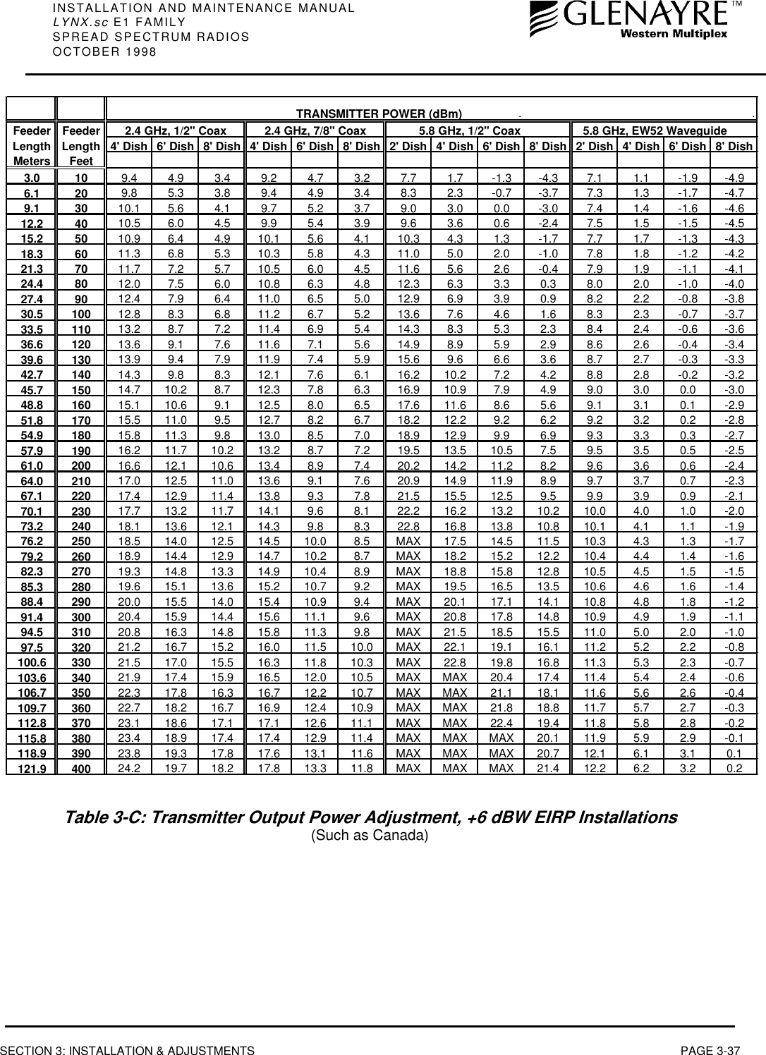
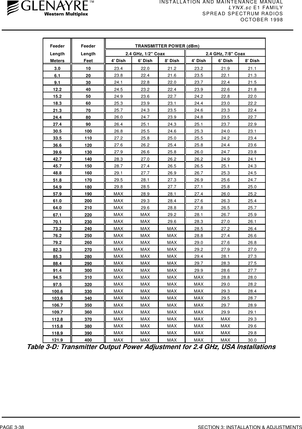
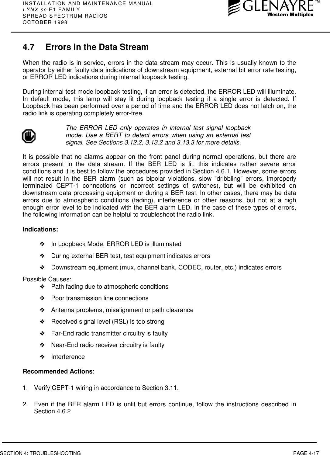
![INSTALLATION AND MAINTENANCE MANUALLYNX.sc E1 FAMILYSPREAD SPECTRUM RADIOSOCTOBER 1998SECTION 3: INSTALLATION & ADJUSTMENTS PAGE 3-393.13.1 Output Power AdjustmentThe LYNX.sc radio requires professional installation. In certain cases, it is necessary to adjust theoutput power from the factory setting, for example:❖to meet EIRP (effective isotropic radiated power) limits, such as +6 dBW in Canada.❖to meet transmitter output limits in the 2.4 GHz band for USA installations.❖to avoid exceeding the maximum far-end RSL of 0 dBm.❖to coordinate a hub or repeater location.To ensure maximum protection of the radio circuits, alwaysensure the antenna connector is terminated when power isapplied.For precise measurement of transmitter power, a calibrated RF power meter (such as the HP435B with Power Sensor HP8481) is recommended. This power sensor can be connected directlyto the output of the radio without exceeding the power rating. With some power meters, it may benecessary to place a calibrated in-line fixed attenuator between the radio antenna port and thepower meter so as to not exceed the power meter’s maximum input level. Thruline power metersdo not operate at LYNX.sc RF frequencies.If adjusting the output power to meet an EIRP limit, it will be first necessary to calculate the overallsystem gains and losses, including feeder losses for the type of transmission line installed and theantenna gain. Also refer to Table 3-C or 3-D for transmitter output power settings where installedwith various transmission line lengths and antenna sizes. You may determine the radio transmitpower for EIRP limited installations by the following equation:Tx Power (dBm) = EIRP Limit(dBm) + Feeder Loss(dB) - Antenna Gain(dB)In the USA, 2.4 GHz models have an output limit which is determined by:Tx Power (dBm) = 30 - [(Antenna Gain - 6)/ 3] + Feeder LossOutput power may be adjusted using a small screwdriver and rotating the potentiometer which isrecessed behind the front panel. Clockwise rotation increases output power while counter-clockwise rotation decreases output power.In lieu of a calibrated RF power meter, the PWR test port voltage can be used to estimate theoutput power. Figures 3-16 & 3-17 illustrate the voltage reading for various output power levels.The factory test data sheet should be used to establish a more precise setting of this adjustment.After setting the correct output power, place the cover capfound in the installation accessory kit over the front panelreceptacle.](https://usermanual.wiki/Proxim-Wireless/LYNX96/User-Guide-24828-Page-79.png)