Proxim Wireless MESHMAXMP11R 802.11 a/b/g Access Point User Manual MeshMAX5054Series QIG indd
Proxim Wireless Corporation 802.11 a/b/g Access Point MeshMAX5054Series QIG indd
UserManual.wiki
>
Proxim Wireless
>
MESHMAXMP11R User Manual
>
Users Manual 1
Contents
1.
Users Manual 1
2.
Users Manual 3
3.
Users Manual 4
4.
Users Manual 2 part 1
5.
Users Manual 2 part 2
Users Manual 1
Navigation menu
Upload a User Manual
Namespaces
Wiki Guide
HTML
PDF
Info
Views
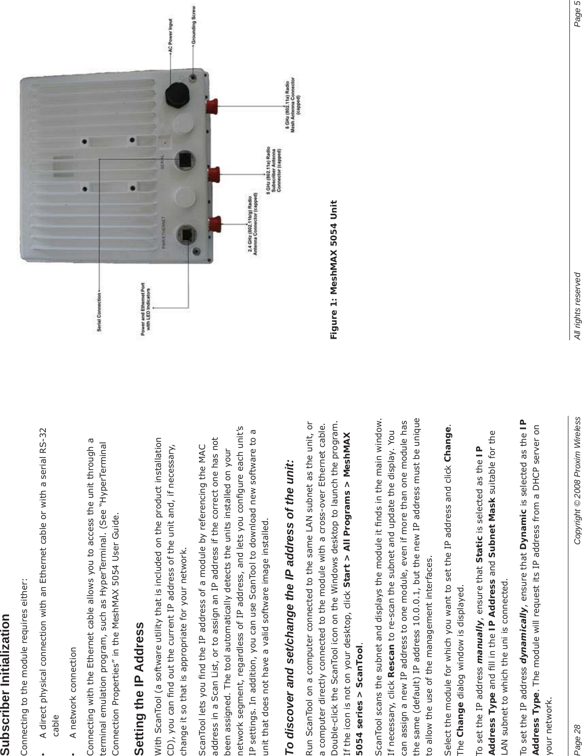
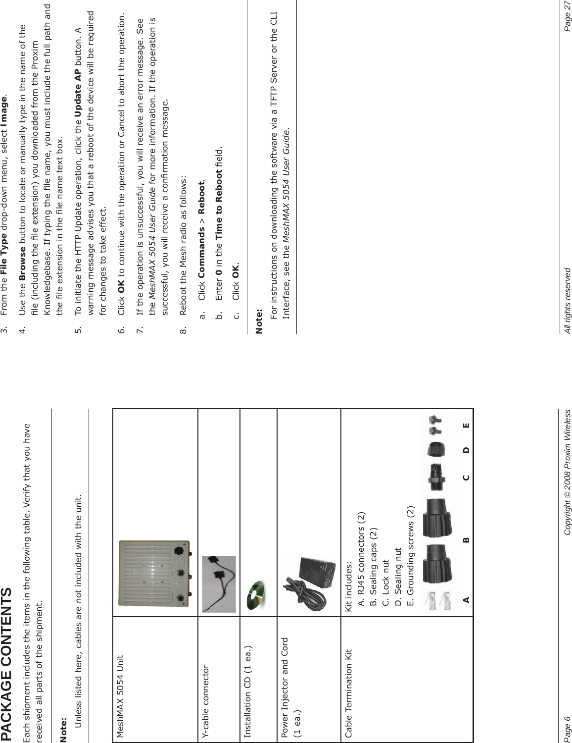
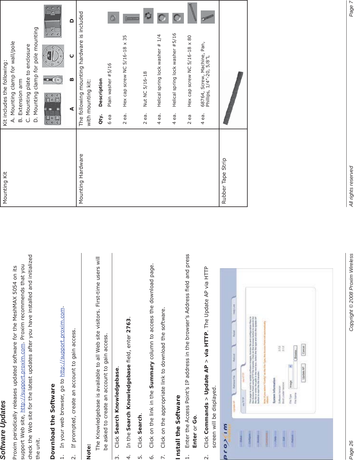
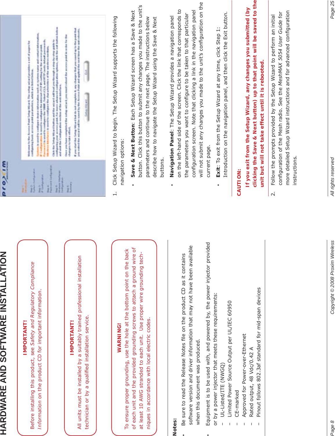
User Manual
Discussion / Help
Navigation