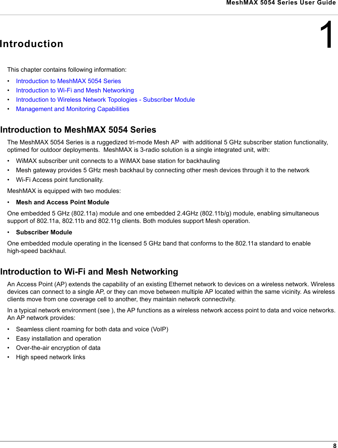
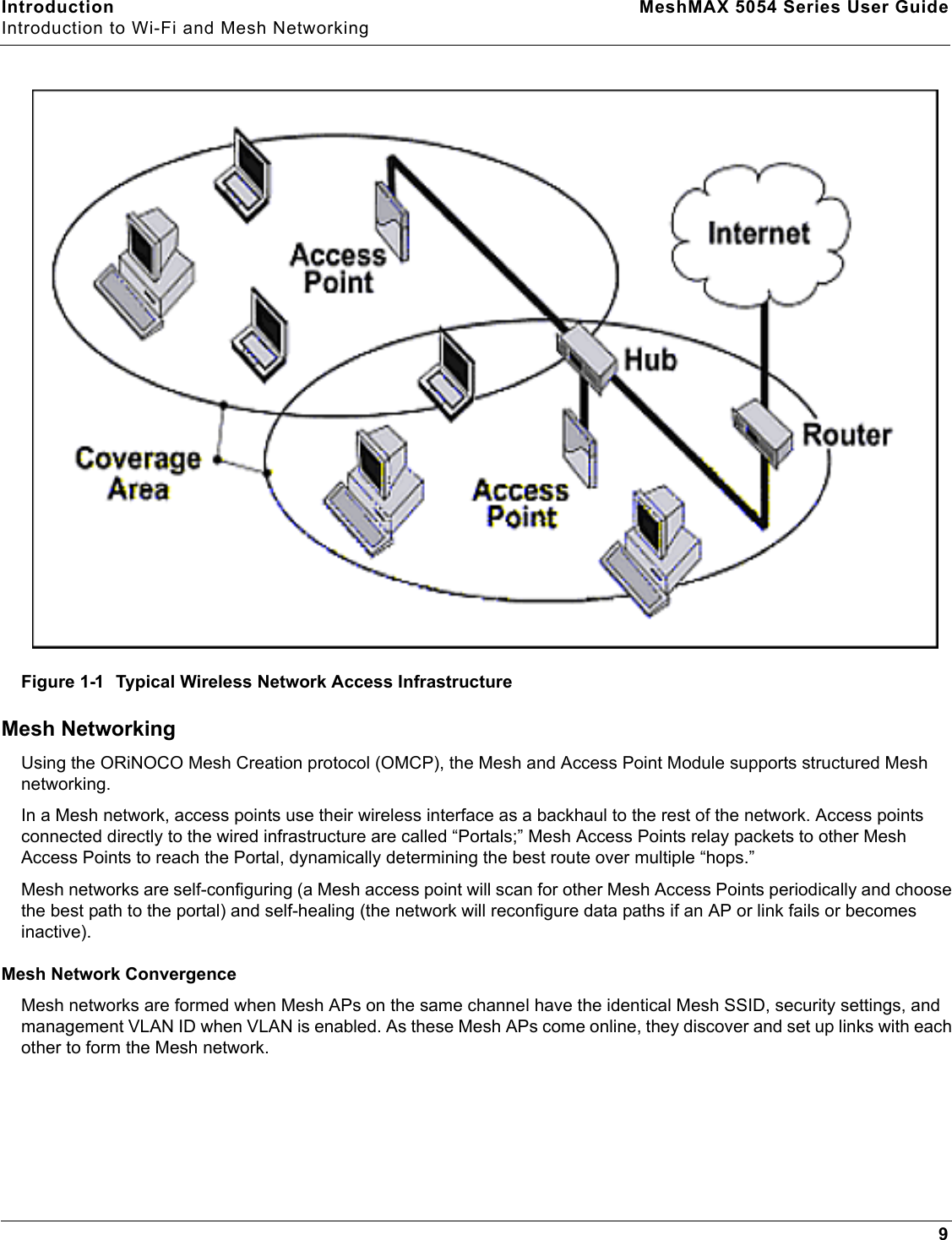
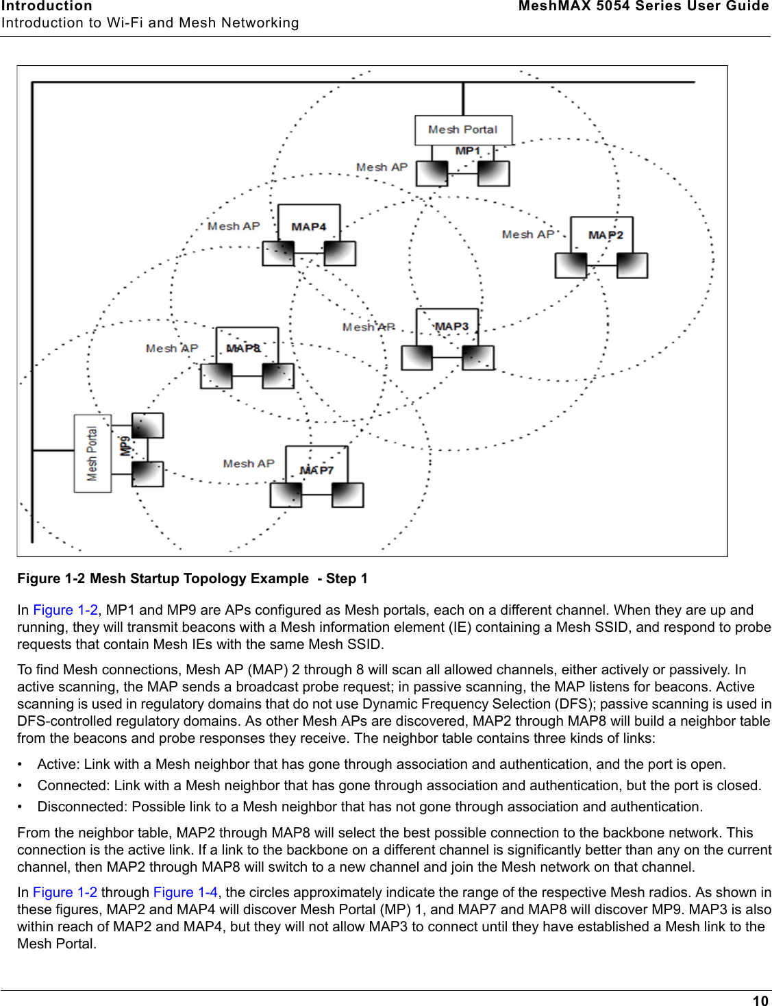
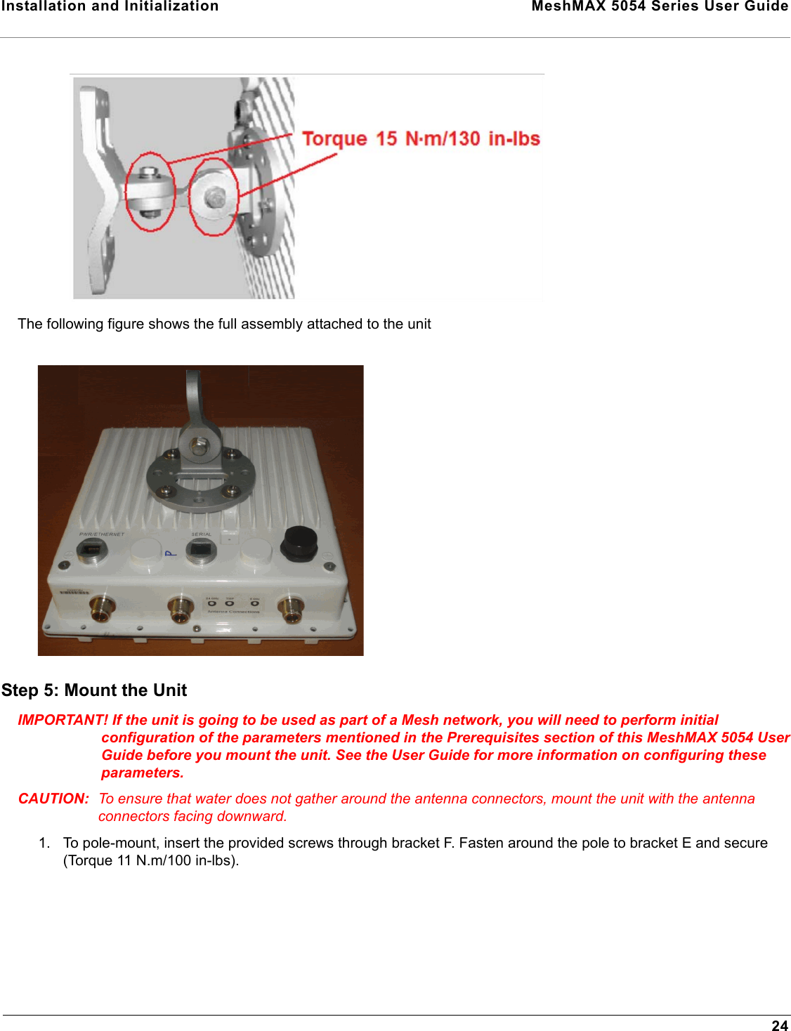
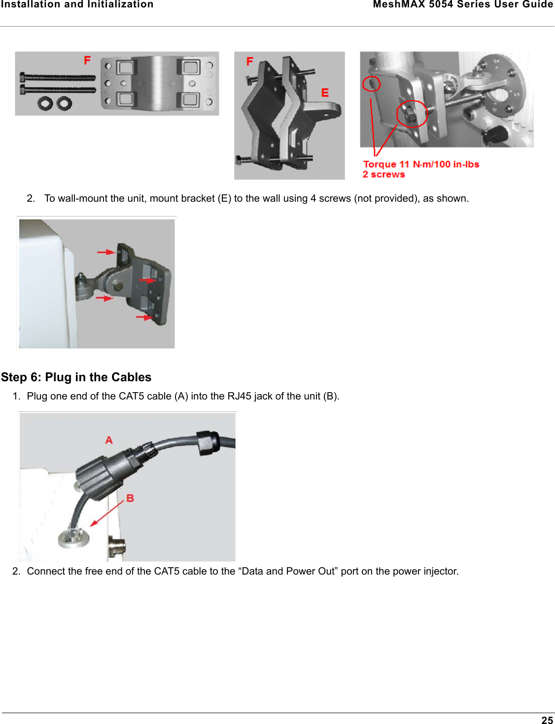
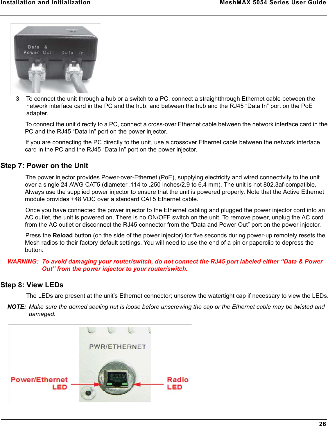
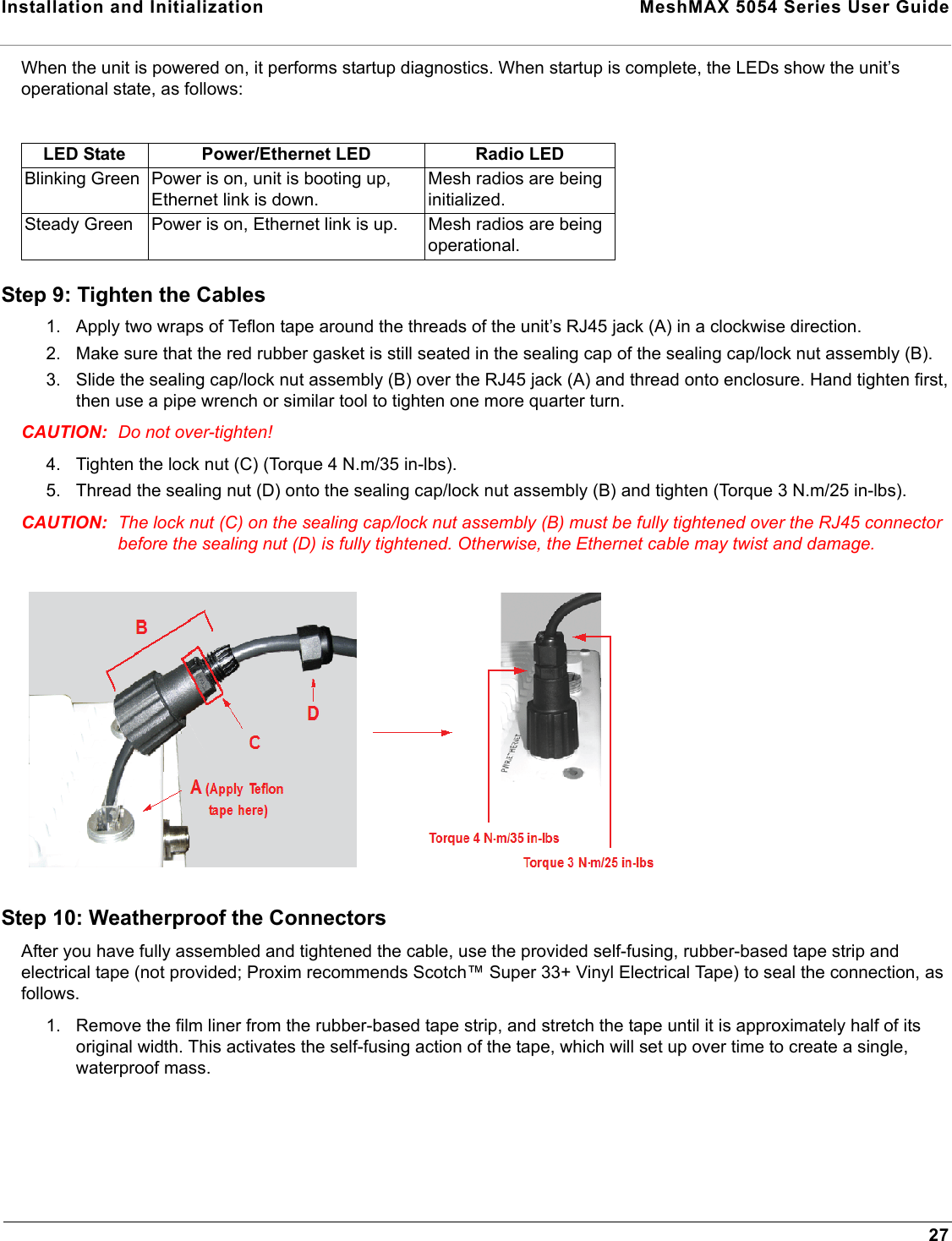
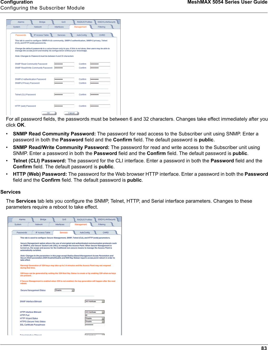
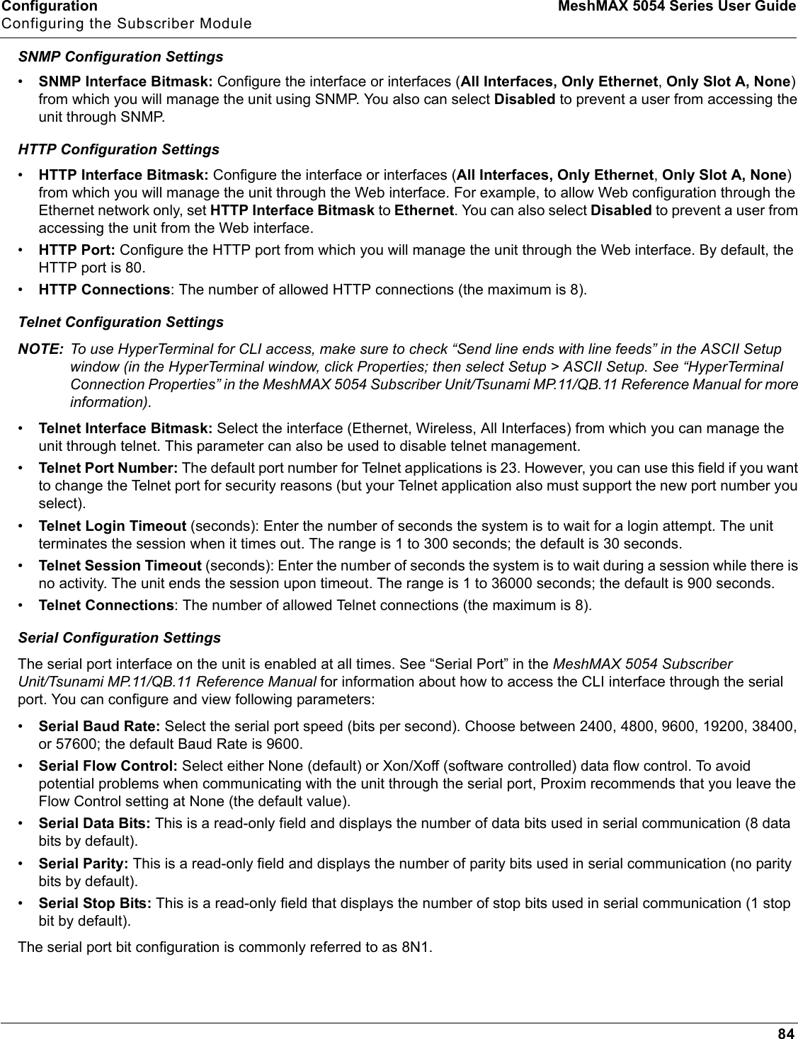
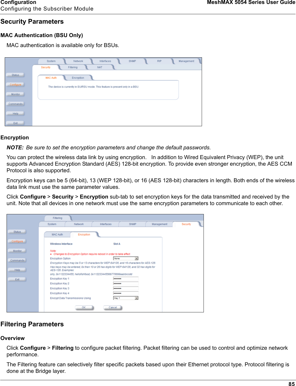
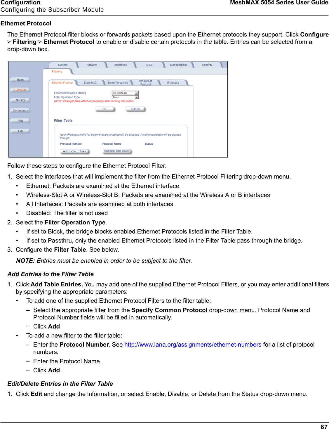
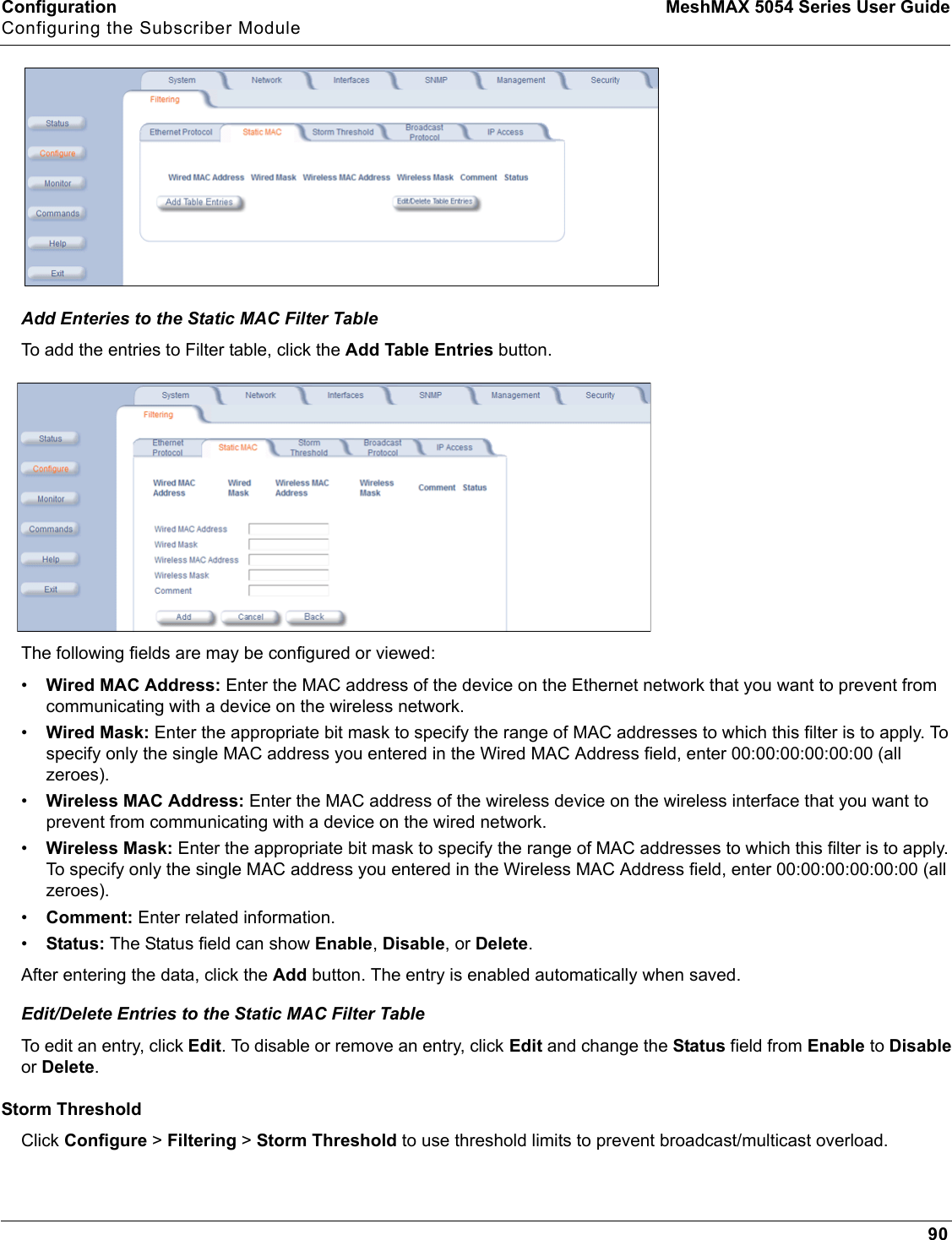
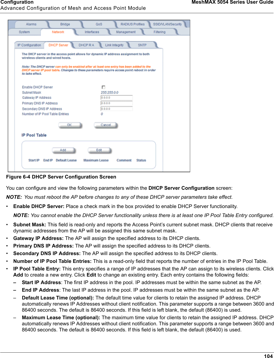
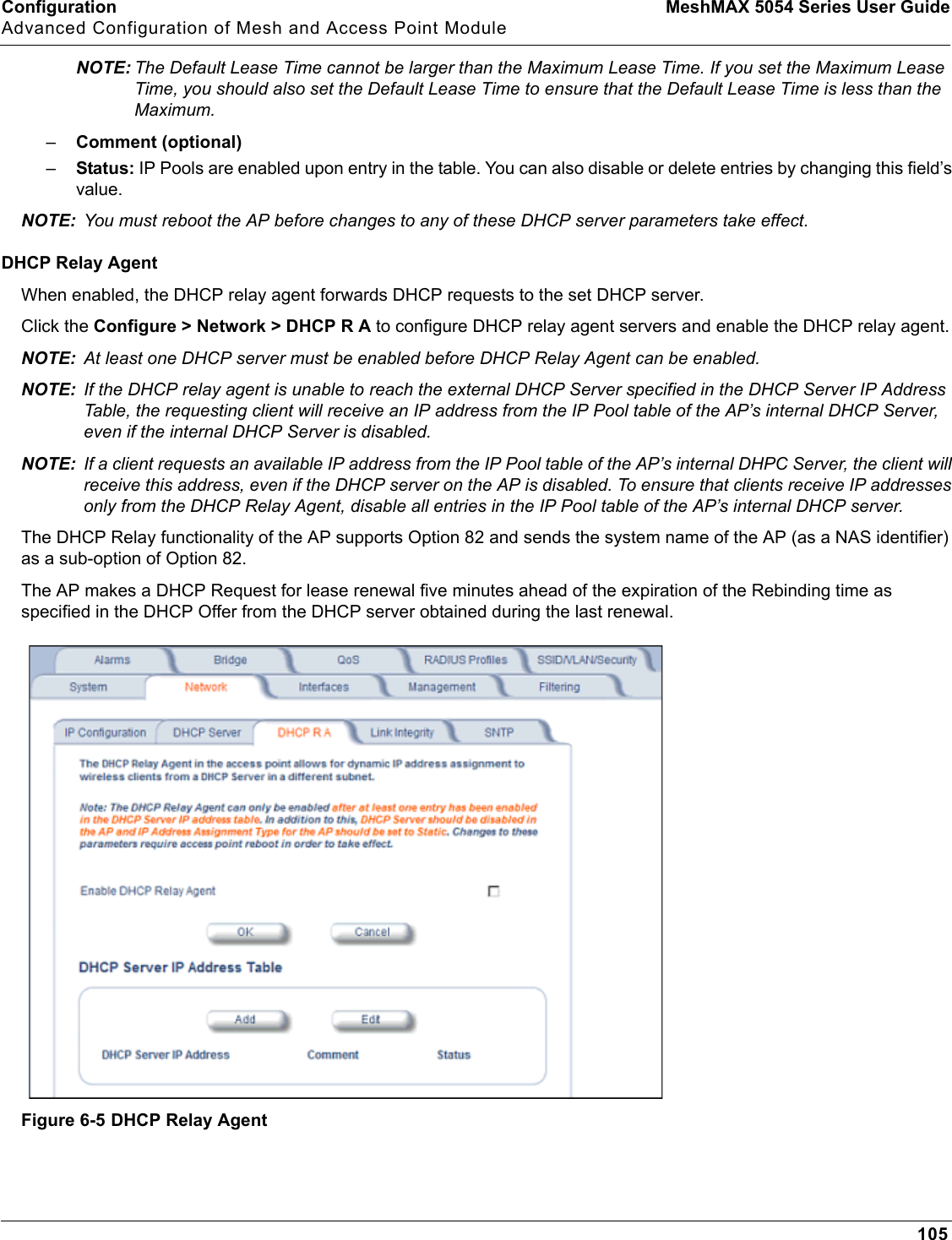
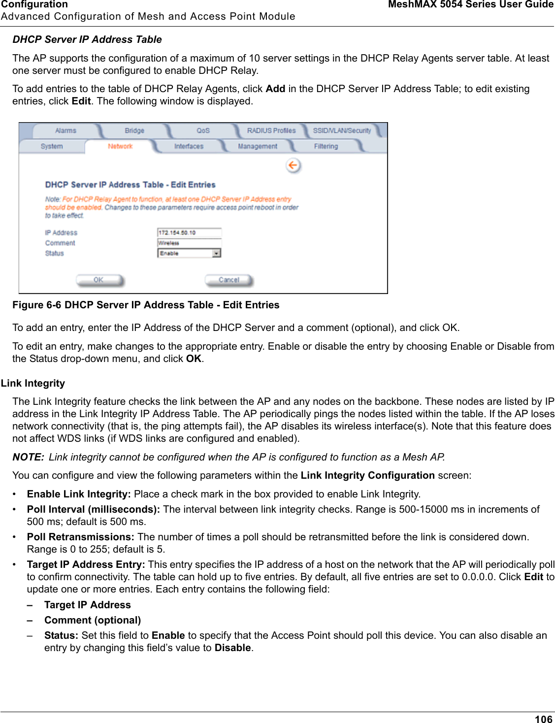
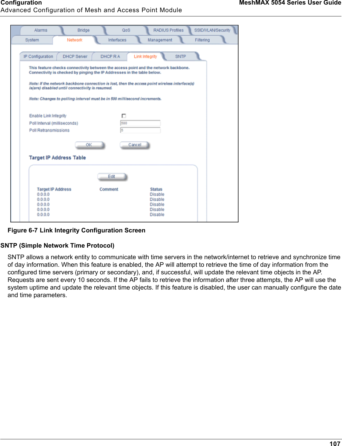
Proxim Wireless MESHMAXMP11R 802.11 a/b/g Access Point User Manual 2 MeshMAX5054Series User Guide
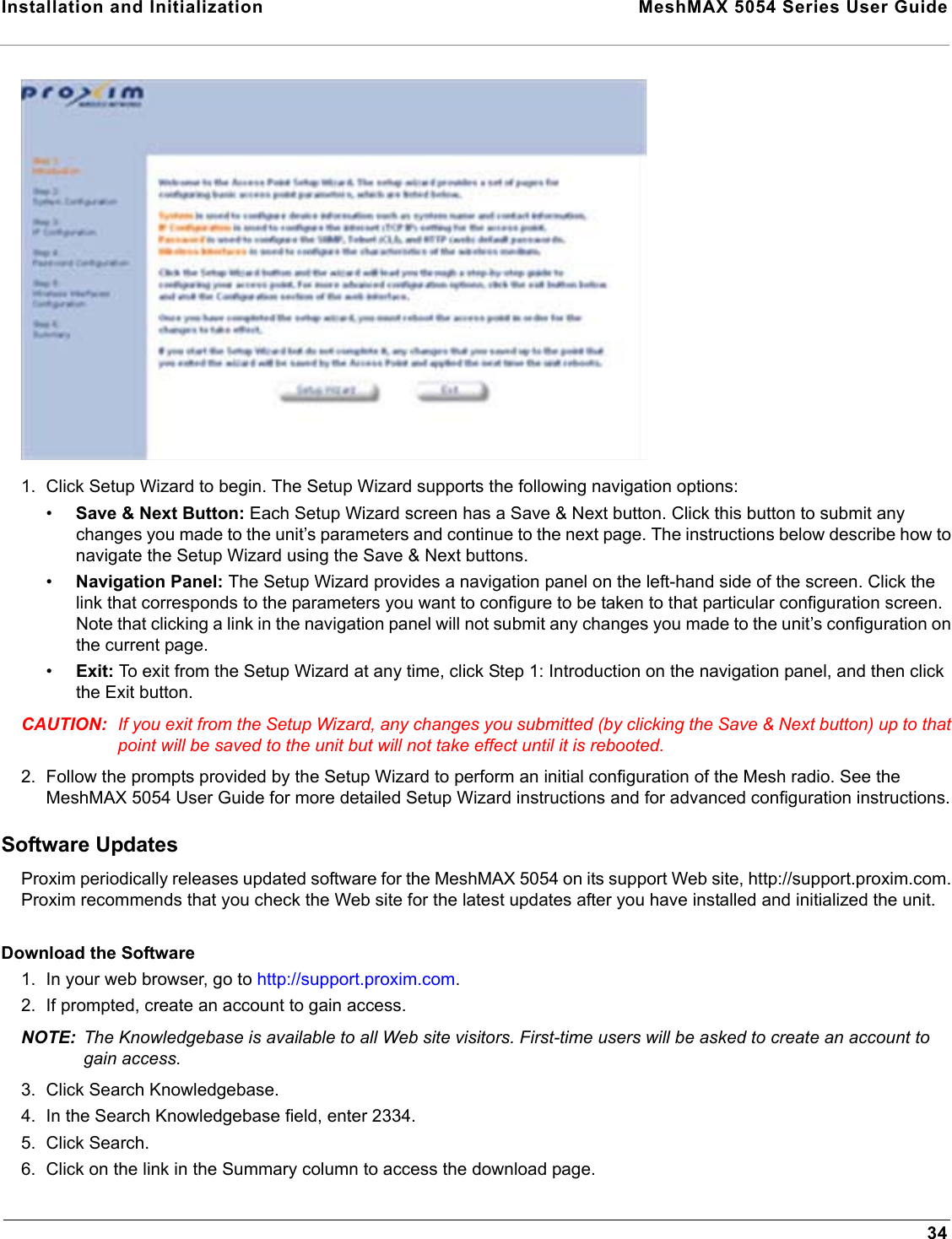
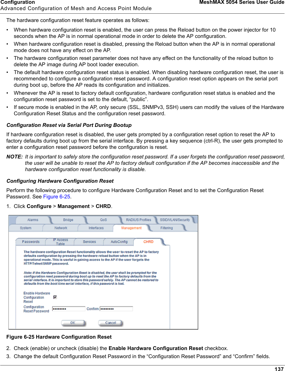
Proxim Wireless Corporation 802.11 a/b/g Access Point 2 MeshMAX5054Series User Guide
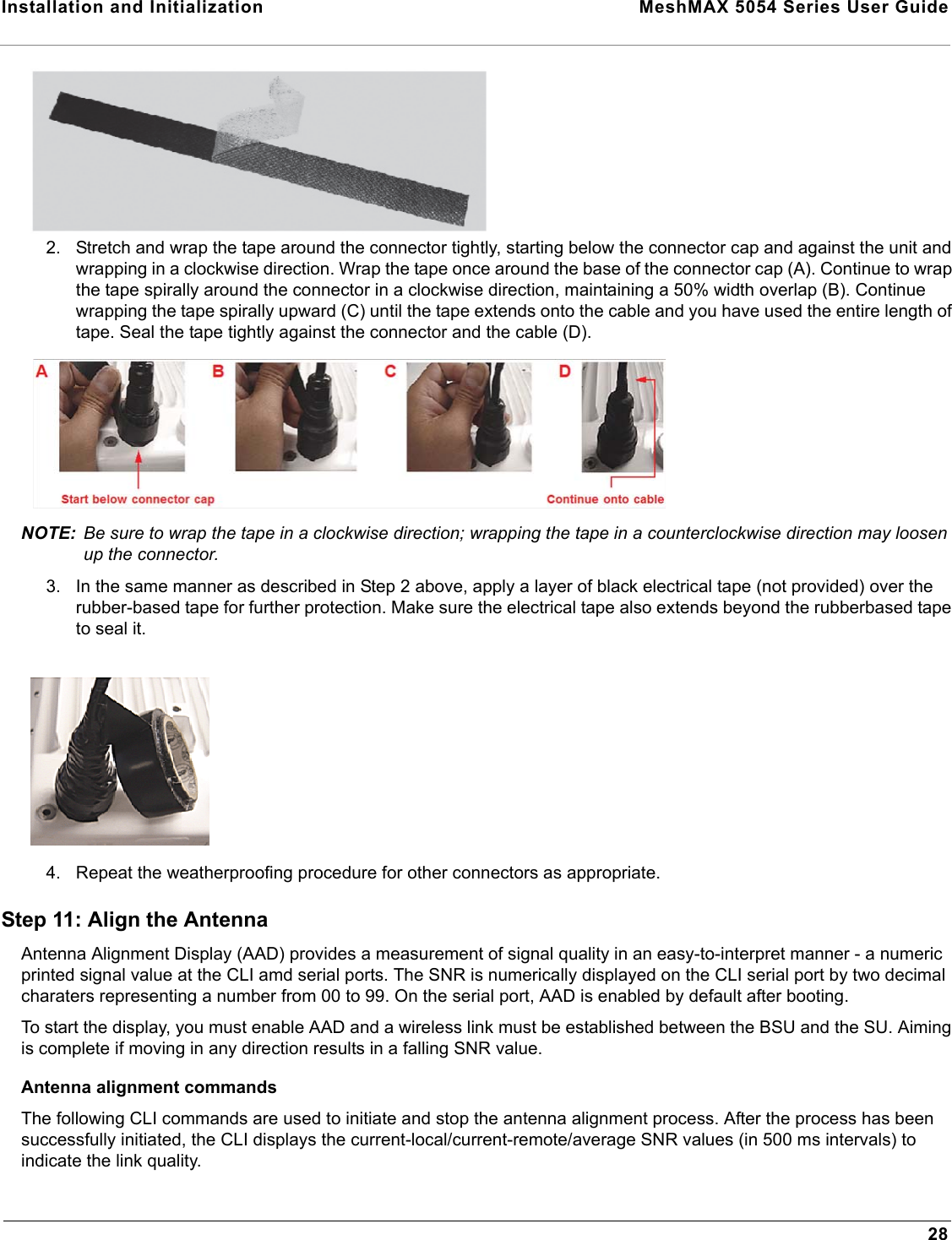
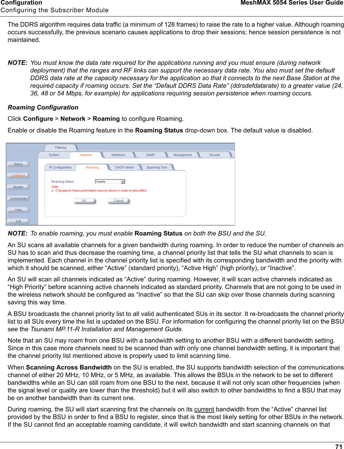
Contents
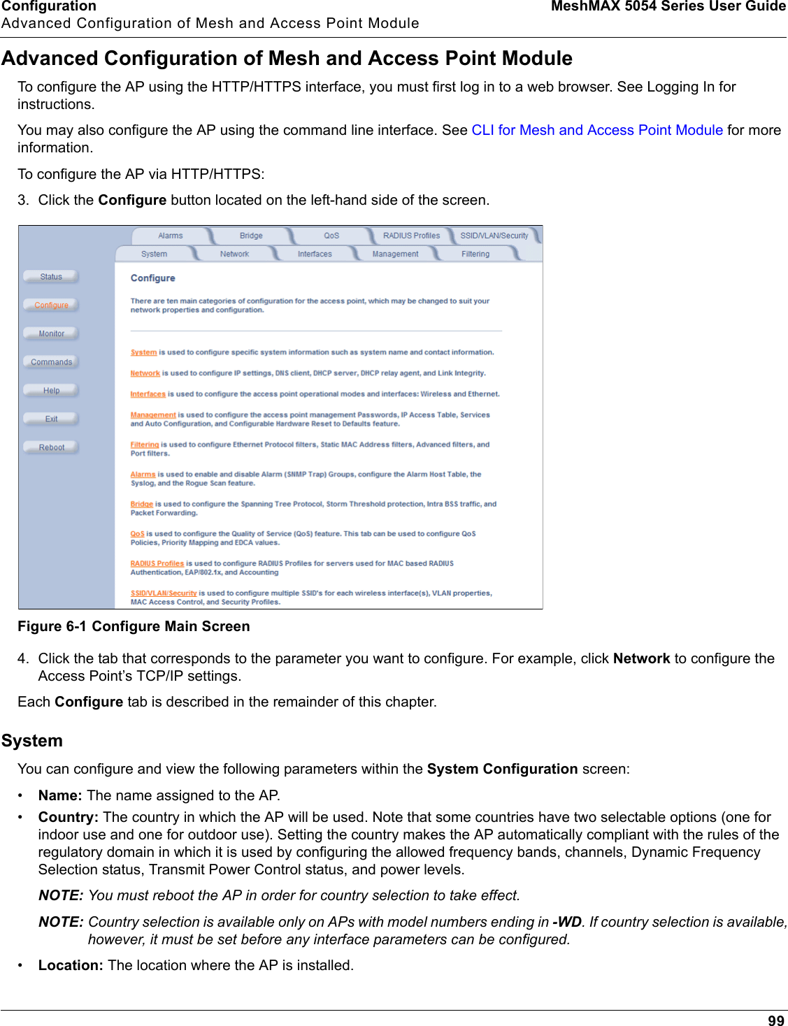
- 1. Users Manual 1
- 2. Users Manual 3
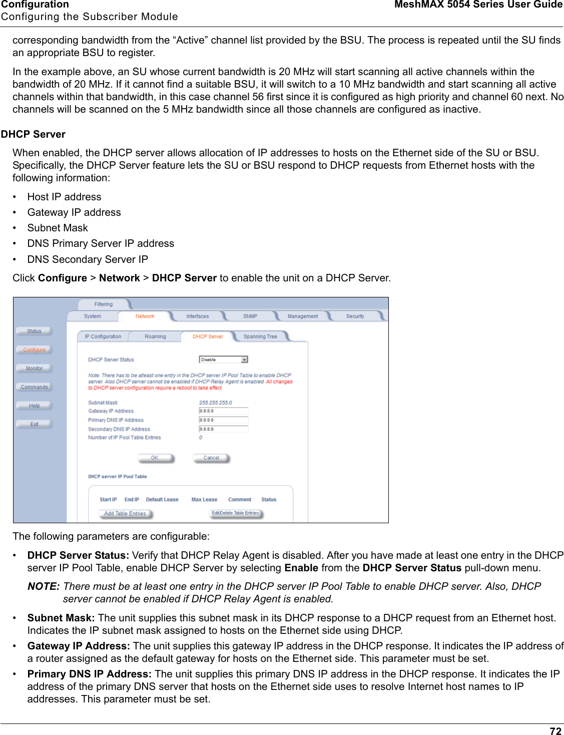
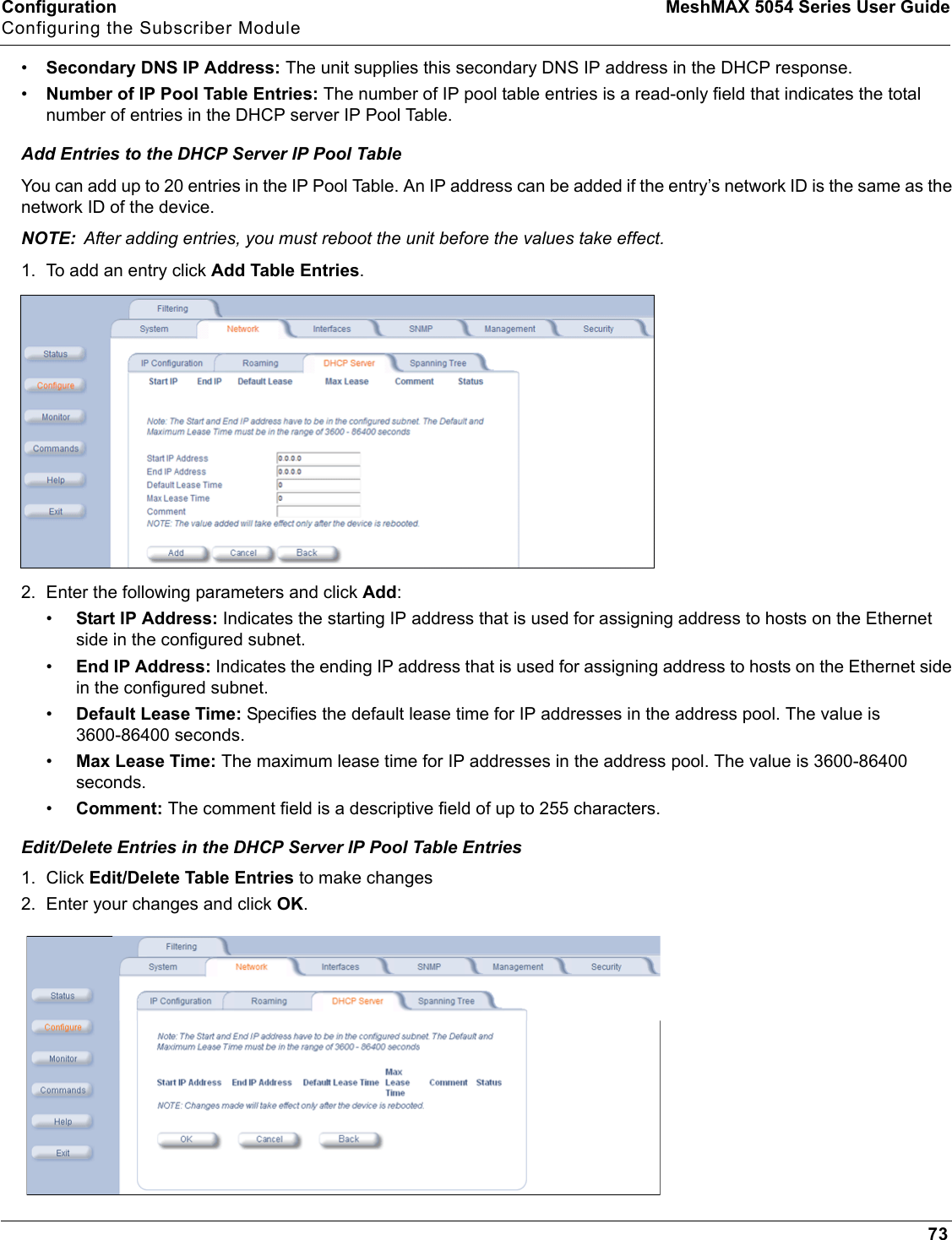
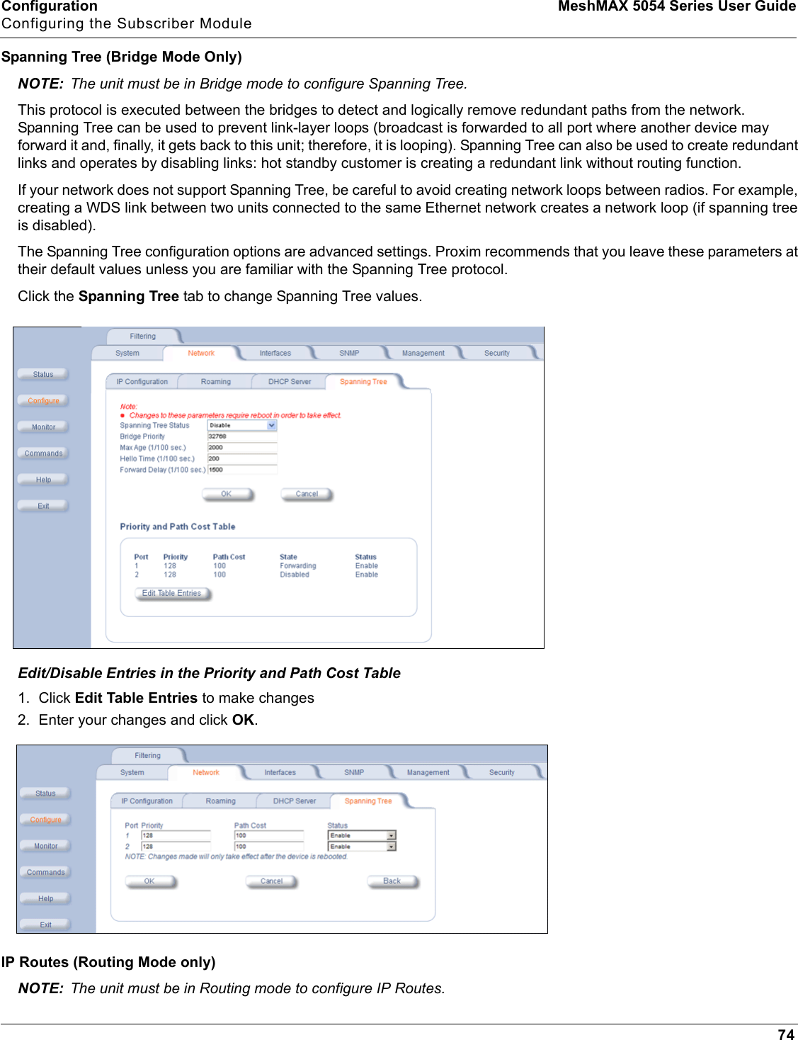
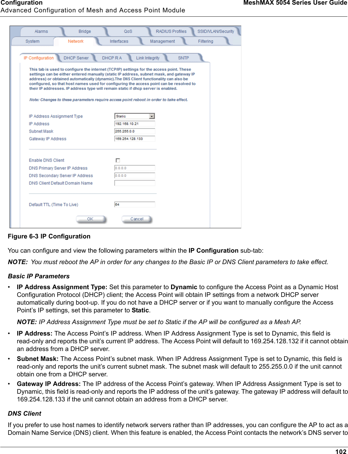
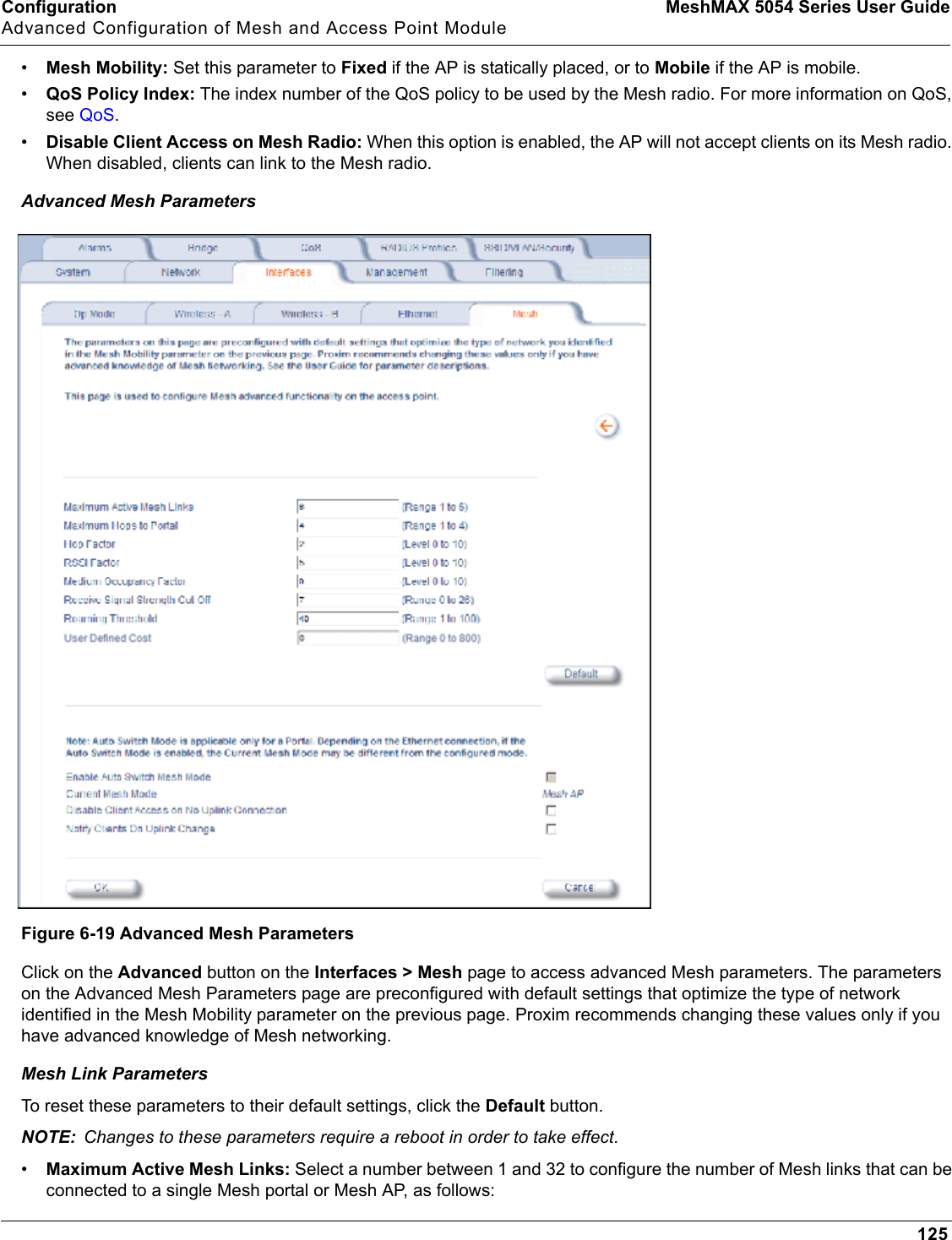
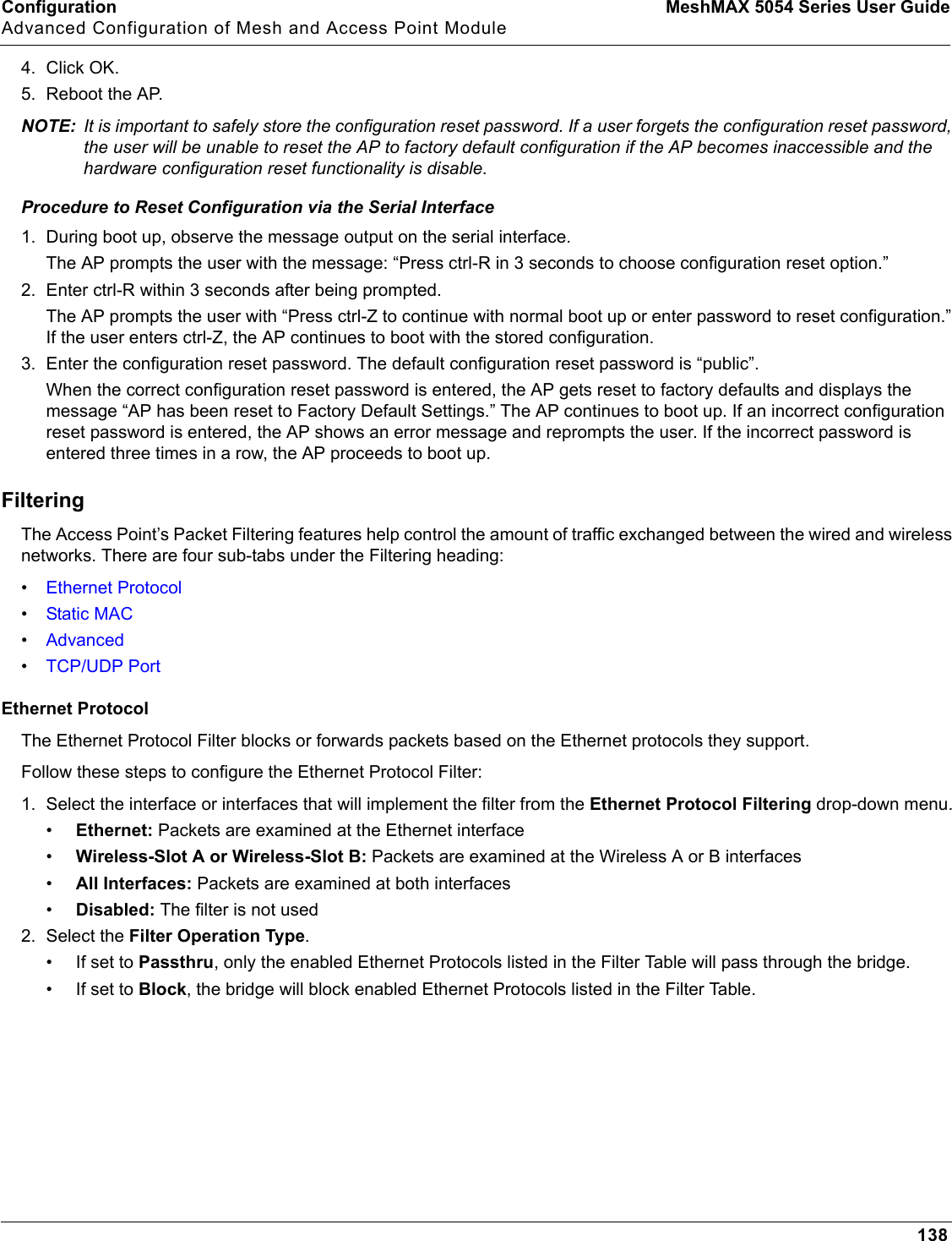
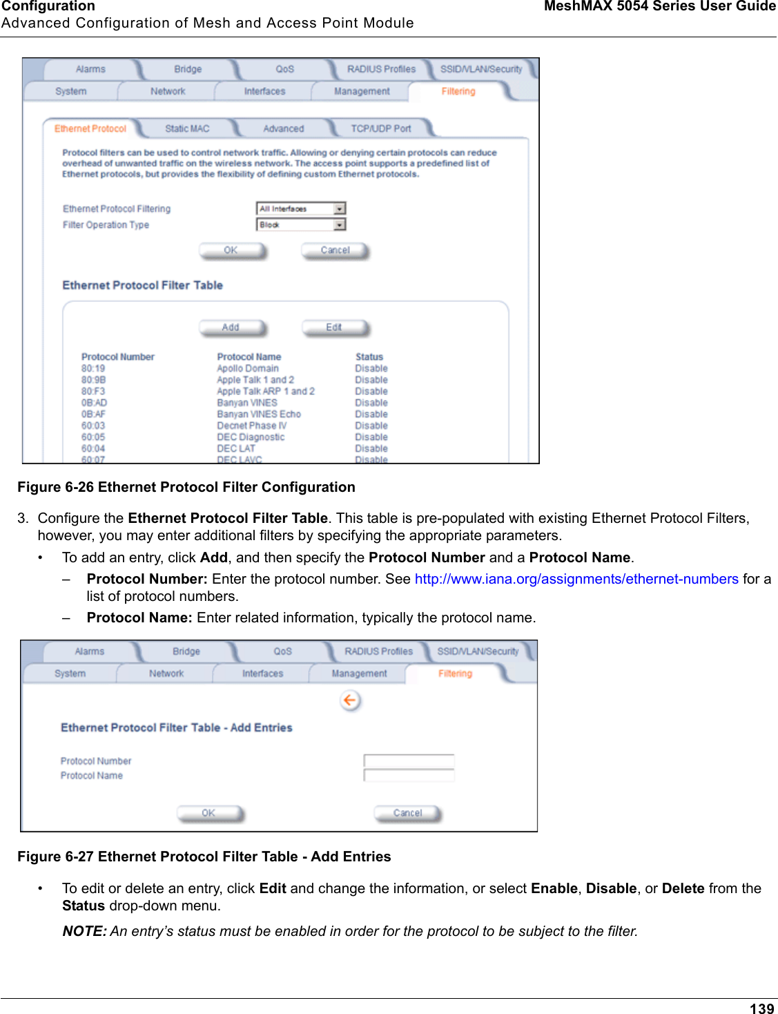
- 3. Users Manual 4
- 4. Users Manual 2 part 1
- 5. Users Manual 2 part 2
Users Manual 2 part 1