Proxim Wireless MESHMAXMP11R 802.11 a/b/g Access Point User Manual 2 MeshMAX5054Series User Guide
Proxim Wireless Corporation 802.11 a/b/g Access Point 2 MeshMAX5054Series User Guide
Contents
- 1. Users Manual 1
- 2. Users Manual 3
- 3. Users Manual 4
- 4. Users Manual 2 part 1
- 5. Users Manual 2 part 2
Users Manual 2 part 1

MeshMAX 5054 Series User Guide
Version 1.0.0

MeshMAX 5054 Series User Guide
12
Copyright
©2008 Proxim Wireless, San Jose, CA. All rights reserved. Covered by one or more of the following U.S. patents: 5,231,634; 5,875,179;
6,006,090; 5,809,060; 6,075,812; 5,077,753. This manual and the software described herein are copyrighted with all rights reserved. No part
of this publication may be reproduced, transmitted, transcribed, stored in a retrieval system, or translated into any language in any form by any
means without the written permission of Proxim Wireless.
Trademarks
Tsunami, Proxim, and the Proxim logo are trademarks of Proxim Wireless. All other trademarks mentioned herein are the property of their
respective owners.
MeshMAX 5054 Series User Guide
PN 75605 , August 2008
IMPORTANT!
Before installing and using this product, see the
Safety and Regulatory Compliance Guide located on the product CD.

MeshMAX 5054 Series User Guide
1
Contents
1 Introduction . . . . . . . . . . . . . . . . . . . . . . . . . . . . . . . . . . . . . . . . . . . . . . . . . . . . . . . . . . . . . . . . . . 8
Introduction to MeshMAX 5054 Series . . . . . . . . . . . . . . . . . . . . . . . . . . . . . . . . . . . . . . . . . . . . . . . . . . . . . 8
Introduction to Wi-Fi and Mesh Networking . . . . . . . . . . . . . . . . . . . . . . . . . . . . . . . . . . . . . . . . . . . . . . . . . 8
Mesh Networking . . . . . . . . . . . . . . . . . . . . . . . . . . . . . . . . . . . . . . . . . . . . . . . . . . . . . . . . . . . . . . . . . . . . . . . . . . . 9
Guidelines for Roaming . . . . . . . . . . . . . . . . . . . . . . . . . . . . . . . . . . . . . . . . . . . . . . . . . . . . . . . . . . . . . . . . . . . . . 13
Introduction to Wireless Network Topologies - Subscriber Module . . . . . . . . . . . . . . . . . . . . . . . . . . . . . . 13
Point-to-Point Link . . . . . . . . . . . . . . . . . . . . . . . . . . . . . . . . . . . . . . . . . . . . . . . . . . . . . . . . . . . . . . . . . . . . . . . . . 14
Point-to-Multipoint Link . . . . . . . . . . . . . . . . . . . . . . . . . . . . . . . . . . . . . . . . . . . . . . . . . . . . . . . . . . . . . . . . . . . . . . 14
Management and Monitoring Capabilities . . . . . . . . . . . . . . . . . . . . . . . . . . . . . . . . . . . . . . . . . . . . . . . . . 15
HTTP/HTTPS Interface . . . . . . . . . . . . . . . . . . . . . . . . . . . . . . . . . . . . . . . . . . . . . . . . . . . . . . . . . . . . . . . . . . . . . 15
Command Line Interface . . . . . . . . . . . . . . . . . . . . . . . . . . . . . . . . . . . . . . . . . . . . . . . . . . . . . . . . . . . . . . . . . . . . 15
SNMP Management . . . . . . . . . . . . . . . . . . . . . . . . . . . . . . . . . . . . . . . . . . . . . . . . . . . . . . . . . . . . . . . . . . . . . . . . 15
SNMPv3 Secure Management . . . . . . . . . . . . . . . . . . . . . . . . . . . . . . . . . . . . . . . . . . . . . . . . . . . . . . . . . . . . . . . . 16
SSH (Secure Shell) Management . . . . . . . . . . . . . . . . . . . . . . . . . . . . . . . . . . . . . . . . . . . . . . . . . . . . . . . . . . . . . 16
2 Installation and Initialization . . . . . . . . . . . . . . . . . . . . . . . . . . . . . . . . . . . . . . . . . . . . . . . . . . . 18
Hardware Overview . . . . . . . . . . . . . . . . . . . . . . . . . . . . . . . . . . . . . . . . . . . . . . . . . . . . . . . . . . . . . . . . . . 19
Package Contents . . . . . . . . . . . . . . . . . . . . . . . . . . . . . . . . . . . . . . . . . . . . . . . . . . . . . . . . . . . . . . . . . . . 20
Installation Procedure . . . . . . . . . . . . . . . . . . . . . . . . . . . . . . . . . . . . . . . . . . . . . . . . . . . . . . . . . . . . . . . . . 22
Step 1: Choose a Location . . . . . . . . . . . . . . . . . . . . . . . . . . . . . . . . . . . . . . . . . . . . . . . . . . . . . . . . . . . . . . . . . . . 22
Step 2: Unpack the Shipping Box . . . . . . . . . . . . . . . . . . . . . . . . . . . . . . . . . . . . . . . . . . . . . . . . . . . . . . . . . . . . . . 22
Step 3: Assemble the Cable . . . . . . . . . . . . . . . . . . . . . . . . . . . . . . . . . . . . . . . . . . . . . . . . . . . . . . . . . . . . . . . . . . 22
Step 4: Assemble Mounting Hardware . . . . . . . . . . . . . . . . . . . . . . . . . . . . . . . . . . . . . . . . . . . . . . . . . . . . . . . . . . 23
Step 5: Mount the Unit . . . . . . . . . . . . . . . . . . . . . . . . . . . . . . . . . . . . . . . . . . . . . . . . . . . . . . . . . . . . . . . . . . . . . . 24
Step 6: Plug in the Cables . . . . . . . . . . . . . . . . . . . . . . . . . . . . . . . . . . . . . . . . . . . . . . . . . . . . . . . . . . . . . . . . . . . 25
Step 7: Power on the Unit. . . . . . . . . . . . . . . . . . . . . . . . . . . . . . . . . . . . . . . . . . . . . . . . . . . . . . . . . . . . . . . . . . . . 26
Step 8: View LEDs . . . . . . . . . . . . . . . . . . . . . . . . . . . . . . . . . . . . . . . . . . . . . . . . . . . . . . . . . . . . . . . . . . . . . . . . . 26
Step 9: Tighten the Cables . . . . . . . . . . . . . . . . . . . . . . . . . . . . . . . . . . . . . . . . . . . . . . . . . . . . . . . . . . . . . . . . . . . 27
Step 10: Weatherproof the Connectors . . . . . . . . . . . . . . . . . . . . . . . . . . . . . . . . . . . . . . . . . . . . . . . . . . . . . . . . . 27
Step 11: Align the Antenna . . . . . . . . . . . . . . . . . . . . . . . . . . . . . . . . . . . . . . . . . . . . . . . . . . . . . . . . . . . . . . . . . . . 28
Step 12: Install Documentation and Software. . . . . . . . . . . . . . . . . . . . . . . . . . . . . . . . . . . . . . . . . . . . . . . . . . . . . 29
Reboot and Reset Functionality for MeshMAX . . . . . . . . . . . . . . . . . . . . . . . . . . . . . . . . . . . . . . . . . . . . . 30
Reboot and Reset Functionality for Mesh and Access Point Module. . . . . . . . . . . . . . . . . . . . . . . . . . . . . . . . . . . 30
Reboot and Reset Functionality for Subscriber Module . . . . . . . . . . . . . . . . . . . . . . . . . . . . . . . . . . . . . . . . . . . . . 30
Unit Initialization . . . . . . . . . . . . . . . . . . . . . . . . . . . . . . . . . . . . . . . . . . . . . . . . . . . . . . . . . . . . . . . . . . . . . 31
Using ScanTool. . . . . . . . . . . . . . . . . . . . . . . . . . . . . . . . . . . . . . . . . . . . . . . . . . . . . . . . . . . . . . . . . . . . . . . . . . . . 31
Scan Tool Instructions . . . . . . . . . . . . . . . . . . . . . . . . . . . . . . . . . . . . . . . . . . . . . . . . . . . . . . . . . . . . . . . . . . . . . . 31
Mesh Initialization . . . . . . . . . . . . . . . . . . . . . . . . . . . . . . . . . . . . . . . . . . . . . . . . . . . . . . . . . . . . . . . . . . . . 33
Logging In. . . . . . . . . . . . . . . . . . . . . . . . . . . . . . . . . . . . . . . . . . . . . . . . . . . . . . . . . . . . . . . . . . . . . . . . . . . . . . . . 33
Using the Setup Wizard . . . . . . . . . . . . . . . . . . . . . . . . . . . . . . . . . . . . . . . . . . . . . . . . . . . . . . . . . . . . . . . . . . . . . 33

MeshMAX 5054 Series User Guide
2
Software Updates. . . . . . . . . . . . . . . . . . . . . . . . . . . . . . . . . . . . . . . . . . . . . . . . . . . . . . . . . . . . . . . . . . . . . . . . . . 34
Subscriber Initialization . . . . . . . . . . . . . . . . . . . . . . . . . . . . . . . . . . . . . . . . . . . . . . . . . . . . . . . . . . . . . . . 36
Setting the IP Address . . . . . . . . . . . . . . . . . . . . . . . . . . . . . . . . . . . . . . . . . . . . . . . . . . . . . . . . . . . . . . . . . . . . . . 36
Software Updates. . . . . . . . . . . . . . . . . . . . . . . . . . . . . . . . . . . . . . . . . . . . . . . . . . . . . . . . . . . . . . . . . . . . . . . . . . 37
3 System Overview of Subscriber Module . . . . . . . . . . . . . . . . . . . . . . . . . . . . . . . . . . . . . . . . . 39
Changing Basic Configuration Information . . . . . . . . . . . . . . . . . . . . . . . . . . . . . . . . . . . . . . . . . . . . . . . . . 39
Country and Related Settings . . . . . . . . . . . . . . . . . . . . . . . . . . . . . . . . . . . . . . . . . . . . . . . . . . . . . . . . . . . . . . . . 40
Dynamic Frequency Selection (DFS). . . . . . . . . . . . . . . . . . . . . . . . . . . . . . . . . . . . . . . . . . . . . . . . . . . . . . . . . . . 40
Transmit Power Control . . . . . . . . . . . . . . . . . . . . . . . . . . . . . . . . . . . . . . . . . . . . . . . . . . . . . . . . . . . . . . . . . . . . . 42
SU Registration . . . . . . . . . . . . . . . . . . . . . . . . . . . . . . . . . . . . . . . . . . . . . . . . . . . . . . . . . . . . . . . . . . . . . 42
Dynamic Data Rate Selection (DDRS) . . . . . . . . . . . . . . . . . . . . . . . . . . . . . . . . . . . . . . . . . . . . . . . . . . . . 43
Virtual Local Area Networks (VLANs) . . . . . . . . . . . . . . . . . . . . . . . . . . . . . . . . . . . . . . . . . . . . . . . . . . . . 43
VLAN Modes . . . . . . . . . . . . . . . . . . . . . . . . . . . . . . . . . . . . . . . . . . . . . . . . . . . . . . . . . . . . . . . . . . . . . . . . . . . . . 44
Q-in-Q (VLAN Stacking) . . . . . . . . . . . . . . . . . . . . . . . . . . . . . . . . . . . . . . . . . . . . . . . . . . . . . . . . . . . . . . . . . . . . . 44
VLAN Forwarding. . . . . . . . . . . . . . . . . . . . . . . . . . . . . . . . . . . . . . . . . . . . . . . . . . . . . . . . . . . . . . . . . . . . . . . . . . 44
VLAN Relaying. . . . . . . . . . . . . . . . . . . . . . . . . . . . . . . . . . . . . . . . . . . . . . . . . . . . . . . . . . . . . . . . . . . . . . . . . . . . 44
Management VLAN . . . . . . . . . . . . . . . . . . . . . . . . . . . . . . . . . . . . . . . . . . . . . . . . . . . . . . . . . . . . . . . . . . . . . . . . 44
BSU and SU in Transparent Mode. . . . . . . . . . . . . . . . . . . . . . . . . . . . . . . . . . . . . . . . . . . . . . . . . . . . . . . . . . . . . 45
BSU in Trunk Mode and SU in Trunk/Access Mode . . . . . . . . . . . . . . . . . . . . . . . . . . . . . . . . . . . . . . . . . . . . . . . 45
BSU in Mixed Mode and SU in Mixed, Access, or Trunk Mode . . . . . . . . . . . . . . . . . . . . . . . . . . . . . . . . . . . . . . . 47
Quality of Service (QoS) . . . . . . . . . . . . . . . . . . . . . . . . . . . . . . . . . . . . . . . . . . . . . . . . . . . . . . . . . . . . . . 49
Concepts and Definitions . . . . . . . . . . . . . . . . . . . . . . . . . . . . . . . . . . . . . . . . . . . . . . . . . . . . . . . . . . . . . . . . . . . . 49
4 Basic Management of Subscriber Module . . . . . . . . . . . . . . . . . . . . . . . . . . . . . . . . . . . . . . . . 54
Navigation . . . . . . . . . . . . . . . . . . . . . . . . . . . . . . . . . . . . . . . . . . . . . . . . . . . . . . . . . . . . . . . . . . . . . . . . . 54
Rebooting and Resetting . . . . . . . . . . . . . . . . . . . . . . . . . . . . . . . . . . . . . . . . . . . . . . . . . . . . . . . . . . . . . . 55
Rebooting. . . . . . . . . . . . . . . . . . . . . . . . . . . . . . . . . . . . . . . . . . . . . . . . . . . . . . . . . . . . . . . . . . . . . . . . . . . . . . . . 55
Resetting Hardware . . . . . . . . . . . . . . . . . . . . . . . . . . . . . . . . . . . . . . . . . . . . . . . . . . . . . . . . . . . . . . . . . . . . . . . . 55
Soft Reset to Factory Default . . . . . . . . . . . . . . . . . . . . . . . . . . . . . . . . . . . . . . . . . . . . . . . . . . . . . . . . . . . . . . . . . 55
Reset and Reboot Functionality . . . . . . . . . . . . . . . . . . . . . . . . . . . . . . . . . . . . . . . . . . . . . . . . . . . . . . . . . . . . . . . 55
General Configuration Settings . . . . . . . . . . . . . . . . . . . . . . . . . . . . . . . . . . . . . . . . . . . . . . . . . . . . . . . . . 56
Monitoring Settings . . . . . . . . . . . . . . . . . . . . . . . . . . . . . . . . . . . . . . . . . . . . . . . . . . . . . . . . . . . . . . . . . . 57
Security Settings . . . . . . . . . . . . . . . . . . . . . . . . . . . . . . . . . . . . . . . . . . . . . . . . . . . . . . . . . . . . . . . . . . . . 57
Encryption . . . . . . . . . . . . . . . . . . . . . . . . . . . . . . . . . . . . . . . . . . . . . . . . . . . . . . . . . . . . . . . . . . . . . . . . . . . . . . . 57
Passwords . . . . . . . . . . . . . . . . . . . . . . . . . . . . . . . . . . . . . . . . . . . . . . . . . . . . . . . . . . . . . . . . . . . . . . . . . . . . . . . 57
Default Settings . . . . . . . . . . . . . . . . . . . . . . . . . . . . . . . . . . . . . . . . . . . . . . . . . . . . . . . . . . . . . . . . . . . . . 58
Upgrading the Unit . . . . . . . . . . . . . . . . . . . . . . . . . . . . . . . . . . . . . . . . . . . . . . . . . . . . . . . . . . . . . . . . . . . 59
5 System Status. . . . . . . . . . . . . . . . . . . . . . . . . . . . . . . . . . . . . . . . . . . . . . . . . . . . . . . . . . . . . . . 60
Subscriber Module . . . . . . . . . . . . . . . . . . . . . . . . . . . . . . . . . . . . . . . . . . . . . . . . . . . . . . . . . . . . . . . . . . . 60
Status . . . . . . . . . . . . . . . . . . . . . . . . . . . . . . . . . . . . . . . . . . . . . . . . . . . . . . . . . . . . . . . . . . . . . . . . . . . . . . . . . . . 60

MeshMAX 5054 Series User Guide
3
Contents
Event Log . . . . . . . . . . . . . . . . . . . . . . . . . . . . . . . . . . . . . . . . . . . . . . . . . . . . . . . . . . . . . . . . . . . . . . . . . . . . . . . . 61
Mesh and Access Point Module . . . . . . . . . . . . . . . . . . . . . . . . . . . . . . . . . . . . . . . . . . . . . . . . . . . . . . . . . 62
6 Configuration . . . . . . . . . . . . . . . . . . . . . . . . . . . . . . . . . . . . . . . . . . . . . . . . . . . . . . . . . . . . . . . 63
Configuring the Subscriber Module . . . . . . . . . . . . . . . . . . . . . . . . . . . . . . . . . . . . . . . . . . . . . . . . . . . . . . 65
System Parameters . . . . . . . . . . . . . . . . . . . . . . . . . . . . . . . . . . . . . . . . . . . . . . . . . . . . . . . . . . . . . . . . . . . . . . . . 65
Network Parameters. . . . . . . . . . . . . . . . . . . . . . . . . . . . . . . . . . . . . . . . . . . . . . . . . . . . . . . . . . . . . . . . . . . . . . . . 68
Interface Parameters . . . . . . . . . . . . . . . . . . . . . . . . . . . . . . . . . . . . . . . . . . . . . . . . . . . . . . . . . . . . . . . . . . . . . . . 77
SNMP Parameters . . . . . . . . . . . . . . . . . . . . . . . . . . . . . . . . . . . . . . . . . . . . . . . . . . . . . . . . . . . . . . . . . . . . . . . . . 81
Management Parameters . . . . . . . . . . . . . . . . . . . . . . . . . . . . . . . . . . . . . . . . . . . . . . . . . . . . . . . . . . . . . . . . . . . . 82
Security Parameters . . . . . . . . . . . . . . . . . . . . . . . . . . . . . . . . . . . . . . . . . . . . . . . . . . . . . . . . . . . . . . . . . . . . . . . . 85
Filtering Parameters . . . . . . . . . . . . . . . . . . . . . . . . . . . . . . . . . . . . . . . . . . . . . . . . . . . . . . . . . . . . . . . . . . . . . . . . 85
RIP Parameters (Routing Mode Only) . . . . . . . . . . . . . . . . . . . . . . . . . . . . . . . . . . . . . . . . . . . . . . . . . . . . . . . . . . 93
NAT (Routing Mode Only) . . . . . . . . . . . . . . . . . . . . . . . . . . . . . . . . . . . . . . . . . . . . . . . . . . . . . . . . . . . . . . . . . . . 95
Advanced Configuration of Mesh and Access Point Module . . . . . . . . . . . . . . . . . . . . . . . . . . . . . . . . . . . 99
System . . . . . . . . . . . . . . . . . . . . . . . . . . . . . . . . . . . . . . . . . . . . . . . . . . . . . . . . . . . . . . . . . . . . . . . . . . . . . . . . . . 99
Network . . . . . . . . . . . . . . . . . . . . . . . . . . . . . . . . . . . . . . . . . . . . . . . . . . . . . . . . . . . . . . . . . . . . . . . . . . . . . . . . 101
Interfaces . . . . . . . . . . . . . . . . . . . . . . . . . . . . . . . . . . . . . . . . . . . . . . . . . . . . . . . . . . . . . . . . . . . . . . . . . . . . . . . 109
Management. . . . . . . . . . . . . . . . . . . . . . . . . . . . . . . . . . . . . . . . . . . . . . . . . . . . . . . . . . . . . . . . . . . . . . . . . . . . . 127
Filtering. . . . . . . . . . . . . . . . . . . . . . . . . . . . . . . . . . . . . . . . . . . . . . . . . . . . . . . . . . . . . . . . . . . . . . . . . . . . . . . . . 138
Alarms . . . . . . . . . . . . . . . . . . . . . . . . . . . . . . . . . . . . . . . . . . . . . . . . . . . . . . . . . . . . . . . . . . . . . . . . . . . . . . . . . 147
Bridge . . . . . . . . . . . . . . . . . . . . . . . . . . . . . . . . . . . . . . . . . . . . . . . . . . . . . . . . . . . . . . . . . . . . . . . . . . . . . . . . . . 159
QoS . . . . . . . . . . . . . . . . . . . . . . . . . . . . . . . . . . . . . . . . . . . . . . . . . . . . . . . . . . . . . . . . . . . . . . . . . . . . . . . . . . . 162
Radius Profiles . . . . . . . . . . . . . . . . . . . . . . . . . . . . . . . . . . . . . . . . . . . . . . . . . . . . . . . . . . . . . . . . . . . . . . . . . . . 168
SSID/VLAN/Security. . . . . . . . . . . . . . . . . . . . . . . . . . . . . . . . . . . . . . . . . . . . . . . . . . . . . . . . . . . . . . . . . . . . . . . 174
7 Monitoring . . . . . . . . . . . . . . . . . . . . . . . . . . . . . . . . . . . . . . . . . . . . . . . . . . . . . . . . . . . . . . . . . 192
Monitoring Options for Subscriber Module . . . . . . . . . . . . . . . . . . . . . . . . . . . . . . . . . . . . . . . . . . . . . . . . 192
Wireless . . . . . . . . . . . . . . . . . . . . . . . . . . . . . . . . . . . . . . . . . . . . . . . . . . . . . . . . . . . . . . . . . . . . . . . . . . . . . . . . 193
ICMP. . . . . . . . . . . . . . . . . . . . . . . . . . . . . . . . . . . . . . . . . . . . . . . . . . . . . . . . . . . . . . . . . . . . . . . . . . . . . . . . . . . 194
Per Station . . . . . . . . . . . . . . . . . . . . . . . . . . . . . . . . . . . . . . . . . . . . . . . . . . . . . . . . . . . . . . . . . . . . . . . . . . . . . . 194
Features . . . . . . . . . . . . . . . . . . . . . . . . . . . . . . . . . . . . . . . . . . . . . . . . . . . . . . . . . . . . . . . . . . . . . . . . . . . . . . . . 194
Link Test . . . . . . . . . . . . . . . . . . . . . . . . . . . . . . . . . . . . . . . . . . . . . . . . . . . . . . . . . . . . . . . . . . . . . . . . . . . . . . . . 195
Interfaces . . . . . . . . . . . . . . . . . . . . . . . . . . . . . . . . . . . . . . . . . . . . . . . . . . . . . . . . . . . . . . . . . . . . . . . . . . . . . . . 196
IP ARP Table . . . . . . . . . . . . . . . . . . . . . . . . . . . . . . . . . . . . . . . . . . . . . . . . . . . . . . . . . . . . . . . . . . . . . . . . . . . . 197
IP Routes . . . . . . . . . . . . . . . . . . . . . . . . . . . . . . . . . . . . . . . . . . . . . . . . . . . . . . . . . . . . . . . . . . . . . . . . . . . . . . . 197
Learn Table. . . . . . . . . . . . . . . . . . . . . . . . . . . . . . . . . . . . . . . . . . . . . . . . . . . . . . . . . . . . . . . . . . . . . . . . . . . . . . 198
RIP . . . . . . . . . . . . . . . . . . . . . . . . . . . . . . . . . . . . . . . . . . . . . . . . . . . . . . . . . . . . . . . . . . . . . . . . . . . . . . . . . . . . 198
Monitoring Options for Mesh and Access Point Module . . . . . . . . . . . . . . . . . . . . . . . . . . . . . . . . . . . . . . 198
Version . . . . . . . . . . . . . . . . . . . . . . . . . . . . . . . . . . . . . . . . . . . . . . . . . . . . . . . . . . . . . . . . . . . . . . . . . . . . . . . . . 199
ICMP. . . . . . . . . . . . . . . . . . . . . . . . . . . . . . . . . . . . . . . . . . . . . . . . . . . . . . . . . . . . . . . . . . . . . . . . . . . . . . . . . . . 200

MeshMAX 5054 Series User Guide
4
IP/ARP Table . . . . . . . . . . . . . . . . . . . . . . . . . . . . . . . . . . . . . . . . . . . . . . . . . . . . . . . . . . . . . . . . . . . . . . . . . . . . 200
Learn Table . . . . . . . . . . . . . . . . . . . . . . . . . . . . . . . . . . . . . . . . . . . . . . . . . . . . . . . . . . . . . . . . . . . . . . . . . . . . . 201
IAPP . . . . . . . . . . . . . . . . . . . . . . . . . . . . . . . . . . . . . . . . . . . . . . . . . . . . . . . . . . . . . . . . . . . . . . . . . . . . . . . . . . . 201
RADIUS . . . . . . . . . . . . . . . . . . . . . . . . . . . . . . . . . . . . . . . . . . . . . . . . . . . . . . . . . . . . . . . . . . . . . . . . . . . . . . . . 202
Interfaces . . . . . . . . . . . . . . . . . . . . . . . . . . . . . . . . . . . . . . . . . . . . . . . . . . . . . . . . . . . . . . . . . . . . . . . . . . . . . . . 203
Station Statistics . . . . . . . . . . . . . . . . . . . . . . . . . . . . . . . . . . . . . . . . . . . . . . . . . . . . . . . . . . . . . . . . . . . . . . . . . . 205
Mesh Statistics . . . . . . . . . . . . . . . . . . . . . . . . . . . . . . . . . . . . . . . . . . . . . . . . . . . . . . . . . . . . . . . . . . . . . . . . . . . 207
8 Commands . . . . . . . . . . . . . . . . . . . . . . . . . . . . . . . . . . . . . . . . . . . . . . . . . . . . . . . . . . . . . . . . 210
Command Functions for Subscriber Module . . . . . . . . . . . . . . . . . . . . . . . . . . . . . . . . . . . . . . . . . . . . . . 210
Download . . . . . . . . . . . . . . . . . . . . . . . . . . . . . . . . . . . . . . . . . . . . . . . . . . . . . . . . . . . . . . . . . . . . . . . . . . . . . . . 210
Upload . . . . . . . . . . . . . . . . . . . . . . . . . . . . . . . . . . . . . . . . . . . . . . . . . . . . . . . . . . . . . . . . . . . . . . . . . . . . . . . . . .211
Reboot . . . . . . . . . . . . . . . . . . . . . . . . . . . . . . . . . . . . . . . . . . . . . . . . . . . . . . . . . . . . . . . . . . . . . . . . . . . . . . . . . .211
Reset . . . . . . . . . . . . . . . . . . . . . . . . . . . . . . . . . . . . . . . . . . . . . . . . . . . . . . . . . . . . . . . . . . . . . . . . . . . . . . . . . . 212
Help Link . . . . . . . . . . . . . . . . . . . . . . . . . . . . . . . . . . . . . . . . . . . . . . . . . . . . . . . . . . . . . . . . . . . . . . . . . . . . . . . 212
Downgrade. . . . . . . . . . . . . . . . . . . . . . . . . . . . . . . . . . . . . . . . . . . . . . . . . . . . . . . . . . . . . . . . . . . . . . . . . . . . . . 212
Command Function for Mesh and Access Point Module . . . . . . . . . . . . . . . . . . . . . . . . . . . . . . . . . . . . . 213
Introduction to File Transfer via TFTP or HTTP . . . . . . . . . . . . . . . . . . . . . . . . . . . . . . . . . . . . . . . . . . . . . . . . . . 213
Update AP . . . . . . . . . . . . . . . . . . . . . . . . . . . . . . . . . . . . . . . . . . . . . . . . . . . . . . . . . . . . . . . . . . . . . . . . . . . . . . 214
Retrieve File . . . . . . . . . . . . . . . . . . . . . . . . . . . . . . . . . . . . . . . . . . . . . . . . . . . . . . . . . . . . . . . . . . . . . . . . . . . . . 217
Reboot . . . . . . . . . . . . . . . . . . . . . . . . . . . . . . . . . . . . . . . . . . . . . . . . . . . . . . . . . . . . . . . . . . . . . . . . . . . . . . . . . 220
Reset . . . . . . . . . . . . . . . . . . . . . . . . . . . . . . . . . . . . . . . . . . . . . . . . . . . . . . . . . . . . . . . . . . . . . . . . . . . . . . . . . . 220
Help Link . . . . . . . . . . . . . . . . . . . . . . . . . . . . . . . . . . . . . . . . . . . . . . . . . . . . . . . . . . . . . . . . . . . . . . . . . . . . . . . 220
9 Procedures for Subscriber Module. . . . . . . . . . . . . . . . . . . . . . . . . . . . . . . . . . . . . . . . . . . . . 222
TFTP Server Setup . . . . . . . . . . . . . . . . . . . . . . . . . . . . . . . . . . . . . . . . . . . . . . . . . . . . . . . . . . . . . . . . . . . . . . . 222
Web Interface Image File Download . . . . . . . . . . . . . . . . . . . . . . . . . . . . . . . . . . . . . . . . . . . . . . . . . . . . . . . . . . 222
Configuration Backup. . . . . . . . . . . . . . . . . . . . . . . . . . . . . . . . . . . . . . . . . . . . . . . . . . . . . . . . . . . . . . . . . . . . . . 223
Configuration Restore . . . . . . . . . . . . . . . . . . . . . . . . . . . . . . . . . . . . . . . . . . . . . . . . . . . . . . . . . . . . . . . . . . . . . 223
Soft Reset to Factory Default . . . . . . . . . . . . . . . . . . . . . . . . . . . . . . . . . . . . . . . . . . . . . . . . . . . . . . . . . . . . . . . . 224
Hard Reset to Factory Default . . . . . . . . . . . . . . . . . . . . . . . . . . . . . . . . . . . . . . . . . . . . . . . . . . . . . . . . . . . . . . . 224
Forced Reload . . . . . . . . . . . . . . . . . . . . . . . . . . . . . . . . . . . . . . . . . . . . . . . . . . . . . . . . . . . . . . . . . . . . . . . . . . . 224
Image File Download with the Bootloader . . . . . . . . . . . . . . . . . . . . . . . . . . . . . . . . . . . . . . . . . . . . . . . . . . . . . . 224
Download with ScanTool . . . . . . . . . . . . . . . . . . . . . . . . . . . . . . . . . . . . . . . . . . . . . . . . . . . . . . . . . . . . . . . . . . . 224
Download with CLI . . . . . . . . . . . . . . . . . . . . . . . . . . . . . . . . . . . . . . . . . . . . . . . . . . . . . . . . . . . . . . . . . . . . . . . . 225
10 Troubleshooting . . . . . . . . . . . . . . . . . . . . . . . . . . . . . . . . . . . . . . . . . . . . . . . . . . . . . . . . . . . . 227
Troubleshooting for Power-Over-Ethernet (PoE) . . . . . . . . . . . . . . . . . . . . . . . . . . . . . . . . . . . . . . . . . . . 228
Troubleshooting Concepts for Subscriber Module . . . . . . . . . . . . . . . . . . . . . . . . . . . . . . . . . . . . . . . . . . 228
Connectivity Issues . . . . . . . . . . . . . . . . . . . . . . . . . . . . . . . . . . . . . . . . . . . . . . . . . . . . . . . . . . . . . . . . . . . . . . . 228
Communication Issues. . . . . . . . . . . . . . . . . . . . . . . . . . . . . . . . . . . . . . . . . . . . . . . . . . . . . . . . . . . . . . . . . . . . . 229
Setup and Configuration Issues . . . . . . . . . . . . . . . . . . . . . . . . . . . . . . . . . . . . . . . . . . . . . . . . . . . . . . . . . . . . . . 229
VLAN Operation Issues . . . . . . . . . . . . . . . . . . . . . . . . . . . . . . . . . . . . . . . . . . . . . . . . . . . . . . . . . . . . . . . . . . . . 230
Link Problems . . . . . . . . . . . . . . . . . . . . . . . . . . . . . . . . . . . . . . . . . . . . . . . . . . . . . . . . . . . . . . . . . . . . . . . . . . . 230

MeshMAX 5054 Series User Guide
5
Troubleshooting Concepts for Mesh and Access Point Module . . . . . . . . . . . . . . . . . . . . . . . . . . . . . . . . 232
Troubleshooting Concepts . . . . . . . . . . . . . . . . . . . . . . . . . . . . . . . . . . . . . . . . . . . . . . . . . . . . . . . . . . . . . . . . . . 233
Symptoms and Solutions . . . . . . . . . . . . . . . . . . . . . . . . . . . . . . . . . . . . . . . . . . . . . . . . . . . . . . . . . . . . . . . . . . . 233
Recovery Procedures. . . . . . . . . . . . . . . . . . . . . . . . . . . . . . . . . . . . . . . . . . . . . . . . . . . . . . . . . . . . . . . . . . . . . . 236
Related Applications . . . . . . . . . . . . . . . . . . . . . . . . . . . . . . . . . . . . . . . . . . . . . . . . . . . . . . . . . . . . . . . . . . . . . . 240
A Country Codes for Subscriber Module. . . . . . . . . . . . . . . . . . . . . . . . . . . . . . . . . . . . . . . . . . 242
Channels/Frequencies by Country . . . . . . . . . . . . . . . . . . . . . . . . . . . . . . . . . . . . . . . . . . . . . . . . . . . . . . 243
B CLI for Mesh and Access Point Module . . . . . . . . . . . . . . . . . . . . . . . . . . . . . . . . . . . . . . . . . 260
General Notes . . . . . . . . . . . . . . . . . . . . . . . . . . . . . . . . . . . . . . . . . . . . . . . . . . . . . . . . . . . . . . . . . . . . . 261
Prerequisite Skills and Knowledge. . . . . . . . . . . . . . . . . . . . . . . . . . . . . . . . . . . . . . . . . . . . . . . . . . . . . . . . . . . . 261
Notation Conventions. . . . . . . . . . . . . . . . . . . . . . . . . . . . . . . . . . . . . . . . . . . . . . . . . . . . . . . . . . . . . . . . . . . . . . 261
Important Terminology . . . . . . . . . . . . . . . . . . . . . . . . . . . . . . . . . . . . . . . . . . . . . . . . . . . . . . . . . . . . . . . . . . . . . 261
Navigation and Special Keys . . . . . . . . . . . . . . . . . . . . . . . . . . . . . . . . . . . . . . . . . . . . . . . . . . . . . . . . . . . . . . . . 261
CLI Error Messages . . . . . . . . . . . . . . . . . . . . . . . . . . . . . . . . . . . . . . . . . . . . . . . . . . . . . . . . . . . . . . . . . . . . . . . 262
Command Line Interface (CLI) Variations . . . . . . . . . . . . . . . . . . . . . . . . . . . . . . . . . . . . . . . . . . . . . . . . 263
Bootloader CLI . . . . . . . . . . . . . . . . . . . . . . . . . . . . . . . . . . . . . . . . . . . . . . . . . . . . . . . . . . . . . . . . . . . . . . . . . . . 263
CLI Command Types . . . . . . . . . . . . . . . . . . . . . . . . . . . . . . . . . . . . . . . . . . . . . . . . . . . . . . . . . . . . . . . . 265
Operational CLI Commands. . . . . . . . . . . . . . . . . . . . . . . . . . . . . . . . . . . . . . . . . . . . . . . . . . . . . . . . . . . . . . . . . 265
Parameter Control Commands . . . . . . . . . . . . . . . . . . . . . . . . . . . . . . . . . . . . . . . . . . . . . . . . . . . . . . . . . . . . . . 269
Using Tables and Strings . . . . . . . . . . . . . . . . . . . . . . . . . . . . . . . . . . . . . . . . . . . . . . . . . . . . . . . . . . . . . 273
Working with Tables . . . . . . . . . . . . . . . . . . . . . . . . . . . . . . . . . . . . . . . . . . . . . . . . . . . . . . . . . . . . . . . . . . . . . . . 273
Using Strings . . . . . . . . . . . . . . . . . . . . . . . . . . . . . . . . . . . . . . . . . . . . . . . . . . . . . . . . . . . . . . . . . . . . . . . . . . . . 273
Configuring the AP using CLI commands . . . . . . . . . . . . . . . . . . . . . . . . . . . . . . . . . . . . . . . . . . . . . . . . 275
Log into the AP using HyperTerminal. . . . . . . . . . . . . . . . . . . . . . . . . . . . . . . . . . . . . . . . . . . . . . . . . . . . . . . . . . 275
Log into the AP using Telnet . . . . . . . . . . . . . . . . . . . . . . . . . . . . . . . . . . . . . . . . . . . . . . . . . . . . . . . . . . . . . . . . 275
Set Basic Configuration Parameters using CLI Commands . . . . . . . . . . . . . . . . . . . . . . . . . . . . . . . . . . . . . . . . 276
Other Network Settings . . . . . . . . . . . . . . . . . . . . . . . . . . . . . . . . . . . . . . . . . . . . . . . . . . . . . . . . . . . . . . . . . . . . 281
CLI Monitoring Parameters . . . . . . . . . . . . . . . . . . . . . . . . . . . . . . . . . . . . . . . . . . . . . . . . . . . . . . . . . . . 290
Parameter Tables . . . . . . . . . . . . . . . . . . . . . . . . . . . . . . . . . . . . . . . . . . . . . . . . . . . . . . . . . . . . . . . . . . . 291
System Parameters . . . . . . . . . . . . . . . . . . . . . . . . . . . . . . . . . . . . . . . . . . . . . . . . . . . . . . . . . . . . . . . . . . . . . . . 293
Network Parameters . . . . . . . . . . . . . . . . . . . . . . . . . . . . . . . . . . . . . . . . . . . . . . . . . . . . . . . . . . . . . . . . . . . . . . 295
Interface Parameters . . . . . . . . . . . . . . . . . . . . . . . . . . . . . . . . . . . . . . . . . . . . . . . . . . . . . . . . . . . . . . . . . . . . . . 299
Management Parameters. . . . . . . . . . . . . . . . . . . . . . . . . . . . . . . . . . . . . . . . . . . . . . . . . . . . . . . . . . . . . . . . . . . 308
Filtering Parameters. . . . . . . . . . . . . . . . . . . . . . . . . . . . . . . . . . . . . . . . . . . . . . . . . . . . . . . . . . . . . . . . . . . . . . . .311
Alarms Parameters . . . . . . . . . . . . . . . . . . . . . . . . . . . . . . . . . . . . . . . . . . . . . . . . . . . . . . . . . . . . . . . . . . . . . . . 314
Bridge Parameters . . . . . . . . . . . . . . . . . . . . . . . . . . . . . . . . . . . . . . . . . . . . . . . . . . . . . . . . . . . . . . . . . . . . . . . . 316
RADIUS Parameters . . . . . . . . . . . . . . . . . . . . . . . . . . . . . . . . . . . . . . . . . . . . . . . . . . . . . . . . . . . . . . . . . . . . . . 318
Security Parameters. . . . . . . . . . . . . . . . . . . . . . . . . . . . . . . . . . . . . . . . . . . . . . . . . . . . . . . . . . . . . . . . . . . . . . . 319
VLAN/SSID Parameters. . . . . . . . . . . . . . . . . . . . . . . . . . . . . . . . . . . . . . . . . . . . . . . . . . . . . . . . . . . . . . . . . . . . 321
Other Parameters. . . . . . . . . . . . . . . . . . . . . . . . . . . . . . . . . . . . . . . . . . . . . . . . . . . . . . . . . . . . . . . . . . . . . . . . . 321

MeshMAX 5054 Series User Guide
6
Wireless Multimedia Enhancements (WME)/Quality of Service (QoS) parameters. . . . . . . . . . . . . . . . . . . . . . . 322
CLI Batch File . . . . . . . . . . . . . . . . . . . . . . . . . . . . . . . . . . . . . . . . . . . . . . . . . . . . . . . . . . . . . . . . . . . . . . 325
Auto Configuration and the CLI Batch File. . . . . . . . . . . . . . . . . . . . . . . . . . . . . . . . . . . . . . . . . . . . . . . . . . . . . . 325
CLI Batch File Format and Syntax . . . . . . . . . . . . . . . . . . . . . . . . . . . . . . . . . . . . . . . . . . . . . . . . . . . . . . . . . . . . 325
Reboot Behavior . . . . . . . . . . . . . . . . . . . . . . . . . . . . . . . . . . . . . . . . . . . . . . . . . . . . . . . . . . . . . . . . . . . . . . . . . 326
C ASCII Chart for Mesh and Access Point Module . . . . . . . . . . . . . . . . . . . . . . . . . . . . . . . . . . 327
D Technical Specifications . . . . . . . . . . . . . . . . . . . . . . . . . . . . . . . . . . . . . . . . . . . . . . . . . . . . . 328
Part Numbers . . . . . . . . . . . . . . . . . . . . . . . . . . . . . . . . . . . . . . . . . . . . . . . . . . . . . . . . . . . . . . . . . . . . . . 329
MeshMAX 5054 Series . . . . . . . . . . . . . . . . . . . . . . . . . . . . . . . . . . . . . . . . . . . . . . . . . . . . . . . . . . . . . . . . . . . . 329
Regulatory Approval and Frequency Ranges . . . . . . . . . . . . . . . . . . . . . . . . . . . . . . . . . . . . . . . . . . . . . 329
Radio and Transmission Specifications . . . . . . . . . . . . . . . . . . . . . . . . . . . . . . . . . . . . . . . . . . . . . . . . . . 330
Receive Sensitivity . . . . . . . . . . . . . . . . . . . . . . . . . . . . . . . . . . . . . . . . . . . . . . . . . . . . . . . . . . . . . . . . . . 330
Maximum Throughput . . . . . . . . . . . . . . . . . . . . . . . . . . . . . . . . . . . . . . . . . . . . . . . . . . . . . . . . . . . . . . . . . . . . . 330
Transmit Power Settings . . . . . . . . . . . . . . . . . . . . . . . . . . . . . . . . . . . . . . . . . . . . . . . . . . . . . . . . . . . . . . . . . . . 331
Software Features . . . . . . . . . . . . . . . . . . . . . . . . . . . . . . . . . . . . . . . . . . . . . . . . . . . . . . . . . . . . . . . . . . . . . . . . 331
Mesh and Wi-Fi Features. . . . . . . . . . . . . . . . . . . . . . . . . . . . . . . . . . . . . . . . . . . . . . . . . . . . . . . . . . . . . . . . . . . 332
LEDs . . . . . . . . . . . . . . . . . . . . . . . . . . . . . . . . . . . . . . . . . . . . . . . . . . . . . . . . . . . . . . . . . . . . . . . . . . . . . . . . . . 333
Interfaces . . . . . . . . . . . . . . . . . . . . . . . . . . . . . . . . . . . . . . . . . . . . . . . . . . . . . . . . . . . . . . . . . . . . . . . . . . . . . . . 334
Other Specifications . . . . . . . . . . . . . . . . . . . . . . . . . . . . . . . . . . . . . . . . . . . . . . . . . . . . . . . . . . . . . . . . . . . . . . . 334
Electrical . . . . . . . . . . . . . . . . . . . . . . . . . . . . . . . . . . . . . . . . . . . . . . . . . . . . . . . . . . . . . . . . . . . . . . . . . . . . . . . 334
Physical and Environmental Specifications . . . . . . . . . . . . . . . . . . . . . . . . . . . . . . . . . . . . . . . . . . . . . . . . . . . . . 334
MTBF and Warranty. . . . . . . . . . . . . . . . . . . . . . . . . . . . . . . . . . . . . . . . . . . . . . . . . . . . . . . . . . . . . . . . . . . . . . . 334
E Specifications for Mesh and Access Point Module. . . . . . . . . . . . . . . . . . . . . . . . . . . . . . . . 336
Software Features . . . . . . . . . . . . . . . . . . . . . . . . . . . . . . . . . . . . . . . . . . . . . . . . . . . . . . . . . . . . . . . . . . 337
Number of Stations per BSS . . . . . . . . . . . . . . . . . . . . . . . . . . . . . . . . . . . . . . . . . . . . . . . . . . . . . . . . . . . . . . . . 337
Management Functions . . . . . . . . . . . . . . . . . . . . . . . . . . . . . . . . . . . . . . . . . . . . . . . . . . . . . . . . . . . . . . . . . . . . 338
Advanced Bridging Functions . . . . . . . . . . . . . . . . . . . . . . . . . . . . . . . . . . . . . . . . . . . . . . . . . . . . . . . . . . . . . . . 338
Medium Access Control (MAC) Functions . . . . . . . . . . . . . . . . . . . . . . . . . . . . . . . . . . . . . . . . . . . . . . . . . . . . . 338
Security Functions . . . . . . . . . . . . . . . . . . . . . . . . . . . . . . . . . . . . . . . . . . . . . . . . . . . . . . . . . . . . . . . . . . . . . . . . 339
Network Functions . . . . . . . . . . . . . . . . . . . . . . . . . . . . . . . . . . . . . . . . . . . . . . . . . . . . . . . . . . . . . . . . . . . . . . . 340
Available Channels . . . . . . . . . . . . . . . . . . . . . . . . . . . . . . . . . . . . . . . . . . . . . . . . . . . . . . . . . . . . . . . . . 341
F Technical Services and Support . . . . . . . . . . . . . . . . . . . . . . . . . . . . . . . . . . . . . . . . . . . . . . . 342
Obtaining Technical Services and Support . . . . . . . . . . . . . . . . . . . . . . . . . . . . . . . . . . . . . . . . . . . . . . . 343
Support Options . . . . . . . . . . . . . . . . . . . . . . . . . . . . . . . . . . . . . . . . . . . . . . . . . . . . . . . . . . . . . . . . . . . . 344
Proxim eService Web Site Support . . . . . . . . . . . . . . . . . . . . . . . . . . . . . . . . . . . . . . . . . . . . . . . . . . . . . . . . . . . 344
Telephone Support . . . . . . . . . . . . . . . . . . . . . . . . . . . . . . . . . . . . . . . . . . . . . . . . . . . . . . . . . . . . . . . . . . . . . . . . 344
ServPak Support . . . . . . . . . . . . . . . . . . . . . . . . . . . . . . . . . . . . . . . . . . . . . . . . . . . . . . . . . . . . . . . . . . . . . . . . . 344
G Statement of Warranty . . . . . . . . . . . . . . . . . . . . . . . . . . . . . . . . . . . . . . . . . . . . . . . . . . . . . . . 345

MeshMAX 5054 Series User Guide
7
Warranty Coverage . . . . . . . . . . . . . . . . . . . . . . . . . . . . . . . . . . . . . . . . . . . . . . . . . . . . . . . . . . . . . . . . . 345
Repair or Replacement . . . . . . . . . . . . . . . . . . . . . . . . . . . . . . . . . . . . . . . . . . . . . . . . . . . . . . . . . . . . . . 345
Limitations of Warranty. . . . . . . . . . . . . . . . . . . . . . . . . . . . . . . . . . . . . . . . . . . . . . . . . . . . . . . . . . . . . . . . . . . . . 345
Support Procedures . . . . . . . . . . . . . . . . . . . . . . . . . . . . . . . . . . . . . . . . . . . . . . . . . . . . . . . . . . . . . . . . . . . . . . . 345
Telephone Support . . . . . . . . . . . . . . . . . . . . . . . . . . . . . . . . . . . . . . . . . . . . . . . . . . . . . . . . . . . . . . . . . . . . . . . . 345
Other Information . . . . . . . . . . . . . . . . . . . . . . . . . . . . . . . . . . . . . . . . . . . . . . . . . . . . . . . . . . . . . . . . . . . 346
Search Knowledgebase . . . . . . . . . . . . . . . . . . . . . . . . . . . . . . . . . . . . . . . . . . . . . . . . . . . . . . . . . . . . . . . . . . . . 346
Ask a Question or Open an Issue . . . . . . . . . . . . . . . . . . . . . . . . . . . . . . . . . . . . . . . . . . . . . . . . . . . . . . . . . . . . 346
Other Adapter Cards . . . . . . . . . . . . . . . . . . . . . . . . . . . . . . . . . . . . . . . . . . . . . . . . . . . . . . . . . . . . . . . . . . . . . . 346

8
MeshMAX 5054 Series User Guide
Introduction
This chapter contains following information:
•Introduction to MeshMAX 5054 Series
•Introduction to Wi-Fi and Mesh Networking
•Introduction to Wireless Network Topologies - Subscriber Module
•Management and Monitoring Capabilities
Introduction to MeshMAX 5054 Series
The MeshMAX 5054 Series is a ruggedized tri-mode Mesh AP with additional 5 GHz subscriber station functionality,
optimed for outdoor deployments. MeshMAX is 3-radio solution is a single integrated unit, with:
• WiMAX subscriber unit connects to a WiMAX base station for backhauling
• Mesh gateway provides 5 GHz mesh backhaul by connecting other mesh devices through it to the network
• Wi-Fi Access point functionality.
MeshMAX is equipped with two modules:
•Mesh and Access Point Module
One embedded 5 GHz (802.11a) module and one embedded 2.4GHz (802.11b/g) module, enabling simultaneous
support of 802.11a, 802.11b and 802.11g clients. Both modules support Mesh operation.
•Subscriber Module
One embedded module operating in the licensed 5 GHz band that conforms to the 802.11a standard to enable
high-speed backhaul.
Introduction to Wi-Fi and Mesh Networking
An Access Point (AP) extends the capability of an existing Ethernet network to devices on a wireless network. Wireless
devices can connect to a single AP, or they can move between multiple AP located within the same vicinity. As wireless
clients move from one coverage cell to another, they maintain network connectivity.
In a typical network environment (see ), the AP functions as a wireless network access point to data and voice networks.
An AP network provides:
• Seamless client roaming for both data and voice (VoIP)
• Easy installation and operation
• Over-the-air encryption of data
• High speed network links
Introduction MeshMAX 5054 Series User Guide
Introduction to Wi-Fi and Mesh Networking
9
Figure 1-1 Typical Wireless Network Access Infrastructure
Mesh Networking
Using the ORiNOCO Mesh Creation protocol (OMCP), the Mesh and Access Point Module supports structured Mesh
networking.
In a Mesh network, access points use their wireless interface as a backhaul to the rest of the network. Access points
connected directly to the wired infrastructure are called “Portals;” Mesh Access Points relay packets to other Mesh
Access Points to reach the Portal, dynamically determining the best route over multiple “hops.”
Mesh networks are self-configuring (a Mesh access point will scan for other Mesh Access Points periodically and choose
the best path to the portal) and self-healing (the network will reconfigure data paths if an AP or link fails or becomes
inactive).
Mesh Network Convergence
Mesh networks are formed when Mesh APs on the same channel have the identical Mesh SSID, security settings, and
management VLAN ID when VLAN is enabled. As these Mesh APs come online, they discover and set up links with each
other to form the Mesh network.
Introduction MeshMAX 5054 Series User Guide
Introduction to Wi-Fi and Mesh Networking
10
Figure 1-2 Mesh Startup Topology Example - Step 1
In Figure 1-2, MP1 and MP9 are APs configured as Mesh portals, each on a different channel. When they are up and
running, they will transmit beacons with a Mesh information element (IE) containing a Mesh SSID, and respond to probe
requests that contain Mesh IEs with the same Mesh SSID.
To find Mesh connections, Mesh AP (MAP) 2 through 8 will scan all allowed channels, either actively or passively. In
active scanning, the MAP sends a broadcast probe request; in passive scanning, the MAP listens for beacons. Active
scanning is used in regulatory domains that do not use Dynamic Frequency Selection (DFS); passive scanning is used in
DFS-controlled regulatory domains. As other Mesh APs are discovered, MAP2 through MAP8 will build a neighbor table
from the beacons and probe responses they receive. The neighbor table contains three kinds of links:
• Active: Link with a Mesh neighbor that has gone through association and authentication, and the port is open.
• Connected: Link with a Mesh neighbor that has gone through association and authentication, but the port is closed.
• Disconnected: Possible link to a Mesh neighbor that has not gone through association and authentication.
From the neighbor table, MAP2 through MAP8 will select the best possible connection to the backbone network. This
connection is the active link. If a link to the backbone on a different channel is significantly better than any on the current
channel, then MAP2 through MAP8 will switch to a new channel and join the Mesh network on that channel.
In Figure 1-2 through Figure 1-4, the circles approximately indicate the range of the respective Mesh radios. As shown in
these figures, MAP2 and MAP4 will discover Mesh Portal (MP) 1, and MAP7 and MAP8 will discover MP9. MAP3 is also
within reach of MAP2 and MAP4, but they will not allow MAP3 to connect until they have established a Mesh link to the
Mesh Portal.
Introduction MeshMAX 5054 Series User Guide
Introduction to Wi-Fi and Mesh Networking
11
Assume that links are established as shown in Figure 1-3. Solid lines indicate established links.
Figure 1-3 Mesh Startup Topoloy Example - Step 2
After the first Mesh links are formed, MAP2,4,7 and 8 will add the Mesh IE to their beacon and respond to probe requests
with a Mesh IE containing the same Mesh SSID and security settings. Eventually MAP 3 will find both MAP2 and 4 and
will setup a Mesh link with the one with the best path to the portal, say MAP2. Optimal paths have low “path costs;” path
costs are calculated based on the number of hops to the portal, RSSI (relative signal strength), and medium occupancy.
Once MAP4 has established a path to the Mesh portal, MAP 3 will also establish a Mesh link with MAP4, but that
connection will remain inactive. It will only be used as a possible alternative uplink for MAP3, and at the same time an
alternative uplink for MAP4. If for some reason the link from MAP4 to MP1 fails, MAP4 can still reach the backbone via
MAP3 and MAP2. The same goes for other MAPs that discover each other. After a short while, the network in this
example will look like Figure 1-4, where solid lines indicate active Mesh links and dotted lines indicate established but
inactive Mesh links.
Introduction MeshMAX 5054 Series User Guide
Introduction to Wi-Fi and Mesh Networking
12
Figure 1-4 Mesh Startup topologyExample - Step 3
In this example, if MAP8 loses Mesh link to MP9, MAP8 will immediately activate the Mesh link to MAP7. If the link to
MAP7 has a higher path cost than a possible link to MAP4, which has the same Mesh SSID and security mode but is on
a different channel, then MAP7 may decide to switch channels and establish and activate a link to MAP4.
Mesh Network Configuration
In the Mesh and Access Point Module either of the wireless interfaces may be configured for Mesh functionality, with the
following considerations in mind:
• To form or join a Mesh network, Mesh APs must have identical Mesh SSIDs and security modes (None or AES). If
using AES, the shared secret should also be identical.
• All Mesh APs connected to a Portal will be on the same channel. The channel used by the Mesh Portal will determine
the channel used by all of its connected Mesh APs.
• On Mesh APs, Mesh and WDS functionality cannot co-exist on the same wireless interface. Mesh and WDS can
co-exist on Mesh Portals.
• The maximum number of links downlinks from a Mesh Portal to Mesh APs in the tree is 32. Proxim recommends a
maximum of 30-40 APs total per portal (whether connected directly to the Portal or to another Mesh AP) for an
average per-client throughput of 300-500 Kbps. This recommendation is based on the following assumptions:
– 18 Mbps throughput is available at the portal (max is 25 Mbps, but rates decrease as distance between APs
increases).
– 20 wireless clients are supported per AP.

Introduction MeshMAX 5054 Series User Guide
Introduction to Wireless Network Topologies - Subscriber Module
13
– Average utilization (time that a client is actually transferring data) is 10%.
If the conditions on your network are different than the assumptions above, then the maximum number of APs should
be adjusted accordingly.
NOTE: Clients whose traffic must traverse multiple hops in order to reach the portal will have lower throughput than
clients whose traffic traverses fewer hops.
• Although this solution is designed to be flexible and have a short convergence time after a topology change, it is not
recommended for high-speed roaming or a highly dynamic environment.
• The Mesh network assumes that the uplink to the backbone will be provided by Mesh only.
NOTE: To avoid loops, the administrator should not configure alternate links to the backbone through Ethernet or WDS
connections.
• Mesh APs will avoid loops caused by Mesh links; similarly, Spanning Tree will detect and correct loops caused by
WDS and wired links.
NOTE: Neither Mesh APs nor Spanning Tree will detect loops caused by a mixture of Mesh and WDS/wired links.
Administrators should avoid any such scenario while deploying Mesh.
• When VLAN is enabled, all APs in a Mesh network must have the same Management VLAN ID.
For information on configuring Mesh using the HTTP interface, see Mesh. For information on configuring Mesh using the
CLI for Mesh and Access Point Module, in the Command Line Interface chapter.
Guidelines for Roaming
• Typical voice network cell coverages vary based on environment. Proxim recommends having a site survey done
professionally to ensure optimal performance. For professional site surveyors, Ekahau™ Site Survey software is
included in the Xtras folder of the Installation CD.
• An AP can only communicate with client devices that support its wireless standards.
• All Access Points must have the same Network Name to support client roaming.
• All workstations with an 802.11 client adapter installed must use either a Network Name of “any” or the same Network
Name as the Access Points that they will roam between. If an AP has Closed System enabled, a client must have the
same Network Name as the Access Point to communicate.
• All Access Points and clients must have matching security settings to communicate.
• The Access Points’ cells should overlap to ensure that there are no gaps in coverage and to ensure that the roaming
client will always have a connection available. To ensure optimal AP placement, Proxim recommends having a site
survey done professionally to ensure optimal performance. For professional site surveyors, Ekahau™ Site Survey
software is included in the Xtras folder of the Installation CD.
• All Access Points in the same vicinity should use a unique, independent channel. By default, the AP automatically
scans for available channels during boot-up but you can also set the channel manually.
• Access Points that use the same channel should be installed as far away from each other as possible to reduce
potential interference.
• If a Mesh AP switches to a new uplink, by default it will send a deauthentication message to clients connected to it.
Administrators can prevent the sending of this message by disabling the “Notify Clients on Uplink Change” parameter
on the Configure > Interfaces > Mesh > Advanced page.
• In countries that require passive scanning for Mesh, the roam time may be higher.
Introduction to Wireless Network Topologies - Subscriber Module
The unit can be used in various network topologies and combinations. The required equipment depends upon the
wireless network topology you want to build. Make sure all required equipment is available before installing the unit.
You can set up the following types of topologies:
Introduction MeshMAX 5054 Series User Guide
Introduction to Wireless Network Topologies - Subscriber Module
14
• Point-to-Point Link
• Point-to-Multipoint Network
Point-to-Point Link
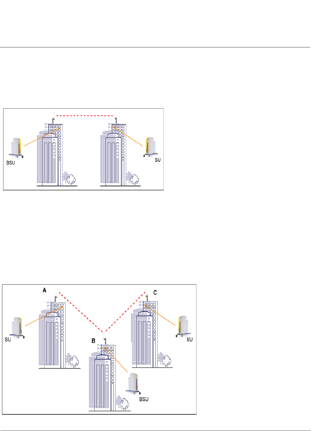
With a BSU and a SU, it is easy to set up a wireless point-to-point link as depicted in the following figure.
Figure 1-5 Point-to-Point Link
A point-to-point link lets you set up a connection between two locations as an alternative to:
• Leased lines in building-to-building connections
• Wired Ethernet backbones between wireless access points in difficult-to-wire environments
Point-to-Multipoint Link
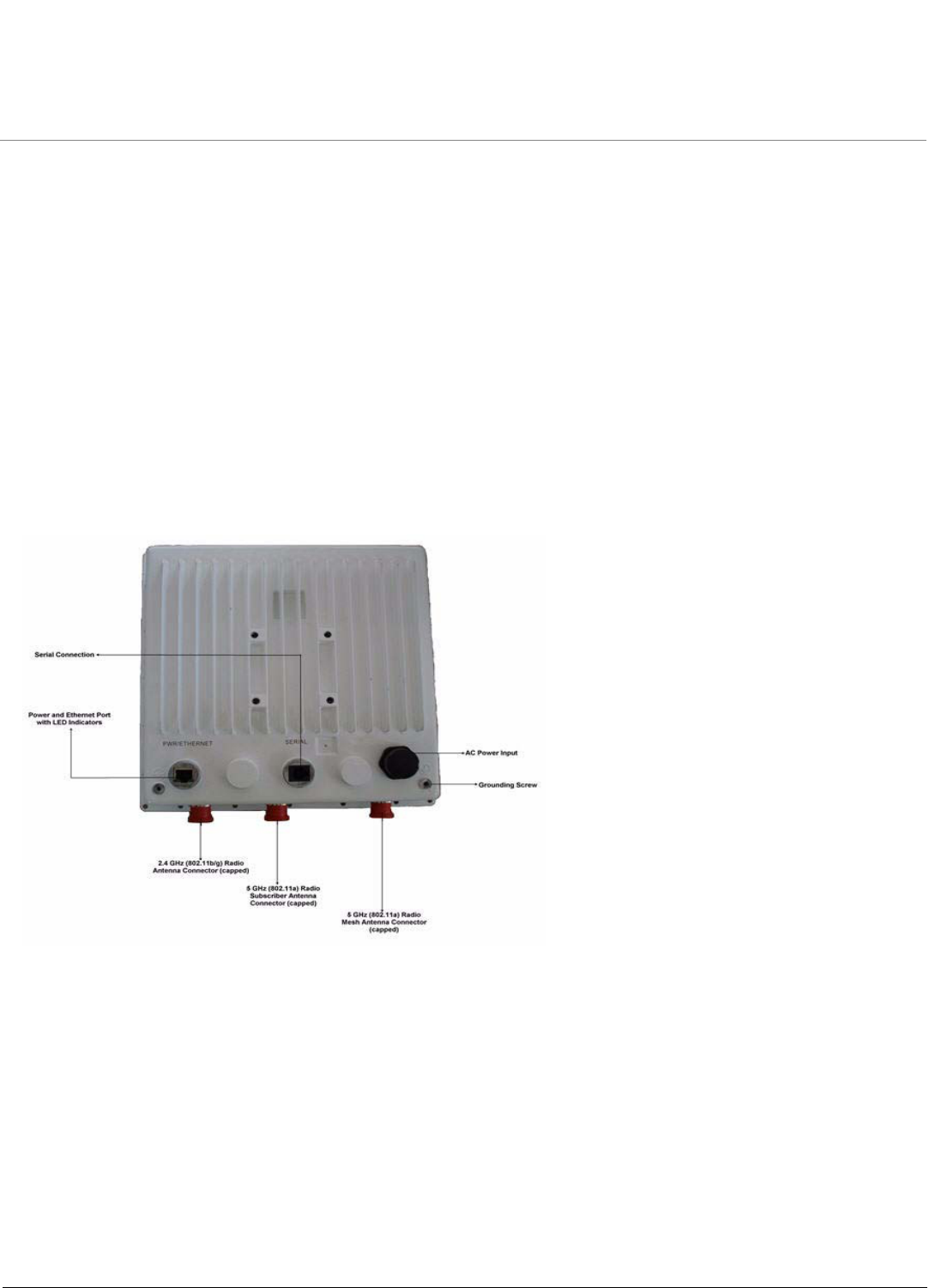
If you want to connect more than two buildings, you can set up a single point-to-multipoint network with a single BSU amd
multiple SUs, as depicted in the following figure.

Introduction MeshMAX 5054 Series User Guide
Management and Monitoring Capabilities
15
Figure 1-6 Point-to-Multipoint Link
Up to 250 SUs can be connected to a BSU. If a BSU already has 250 SU, a new SU cannot be connected to the BSU. In
this figure, the system is designed as follows:
• The central building B is equipped with a BSU, connected to either an omni-directional, or a wide angle antenna.
• The two other buildigs A and C are both equipped with an SU connected to a directional antenna.
Management and Monitoring Capabilities
There are several management and monitoring interfaces available to the network administrator to configure and
manage an AP on the network:
•HTTP/HTTPS Interface (Web Interface)
•Command Line Interface
•SNMP Management
•SSH (Secure Shell) Management
HTTP/HTTPS Interface
The HTTP Interface (Web browser Interface) provides easy access to configuration settings and network statistics from
any computer on the network. You can access the HTTP Interface over your LAN (switch, hub, etc.), over the Internet, or
with a “crossover” Ethernet cable connected directly to your computer’s Ethernet Port.
HTTPS provides an HTTP connection over a Secure Socket Layer. HTTPS is one of three available secure management
options on the AP; the other secure management options are SNMPv3 and SSH. Enabling HTTPS allows the user to
access the AP in a secure fashion using Secure Socket Layer (SSL) over port 443. The AP supports SSLv3 with a 128-bit
encryption certificate maintained by the AP for secure communications between the AP and the HTTP client. All
communications are encrypted using the server and the client-side certificate.
The AP comes pre-installed with all required SSL files: default certificate, private key and SSL Certificate Passphrase
installed.
Command Line Interface
The Command Line Interface (CLI) is a text-based configuration utility that supports a set of keyboard commands and
parameters to configure and manage an AP.
Users enter Command Statements, composed of CLI Commands and their associated parameters. Statements may be
issued from the keyboard for real time control, or from scripts that automate configuration.
For example, when downloading a file, administrators enter the download CLI Command along with IP Address, file
name, and file type parameters.
You access the CLI over a HyperTerminal serial connection or via Telnet. During initial configuration, you can use the CLI
over a serial port connection to configure an Access Point’s IP address. When accessing the CLI via Telnet, you can
communicate with the Access Point from over your LAN (switch, hub, etc.), from over the Internet, or with a “crossover”
Ethernet cable connected directly to your computer’s Ethernet Port. See Command Line Interface (CLI) for more
information on the CLI and for a list of CLI commands and parameters.
SNMP Management
In addition to the HTTP and the CLI interfaces, you can also manage and configure an AP using the Simple Network
Management Protocol (SNMP). Note that this requires an SNMP manager program, like HP Openview or Castlerock’s
SNMPc. The AP supports several Management Information Base (MIB) files that describe the parameters that can be
viewed and/or configured over SNMP:

Introduction MeshMAX 5054 Series User Guide
Management and Monitoring Capabilities
16
• MIB-II (RFC 1213)
• Bridge MIB (RFC 1493)
• Ethernet-like MIB (RFC 1643)
• 802.11 MIB
• ORiNOCO Enterprise MIB
Proxim provides these MIB files on the CD-ROM included with each Access Point. You need to compile one or more of
the above MIBs into your SNMP program’s database before you can manage an Access Point using SNMP. See the
documentation that came with your SNMP manager for instructions on how to compile MIBs.
The Enterprise MIB defines the read and read-write objects that can be viewed or configured using SNMP. These objects
correspond to most of the settings and statistics that are available with the other management interfaces. See the
Enterprise MIB for more information; the MIB can be opened with any text editor, such as Microsoft Word, Notepad, or
WordPad.
NOTE: Using a serial connection, you can access the CLI of the unit through a terminal emulation program such as
Hyperterminal.
For all other modes of connection, you will need the IP address of the unit in order to use the Web Interface,
SNMP, or the CLI via telnet.
SNMPv3 Secure Management
SNMPv3 is based on the existing SNMP framework, but addresses security requirements for device and network
management.
The security threats addressed by Secure Management are:
•Modification of information: An entity could alter an in-transit message generated by an authorized entity in such a
way as to effect unauthorized management operations, including the setting of object values. The essence of this
threat is that an unauthorized entity could change any management parameter, including those related to
configuration, operations, and accounting.
•Masquerade: Management operations that are not authorized for some entity may be attempted by that entity by
assuming the identity of an authorized entity.
•Message stream modification: SNMP is designed to operate over a connectionless transport protocol. There is a
threat that SNMP messages could be reordered, delayed, or replayed (duplicated) to effect unauthorized
management operations. For example, a message to reboot a device could be copied and replayed later.
•Disclosure: An entity could observe exchanges between a manager and an agent and thereby could learn of notifiable
events and the values of managed objects. For example, the observation of a set command that changes passwords
would enable an attacker to learn the new passwords.
To address the security threats listed above, SNMPv3 provides the following when secure management is enabled:
• Authentication: Provides data integrity and data origin authentication.
• Privacy (a.k.a Encryption): Protects against disclosure of message payload.
• Access Control: Controls and authorizes access to managed objects.
The default SNMPv3 username is administrator, with SHA authentication, and DES privacy protocol.
SSH (Secure Shell) Management
You may securely also manage the AP using SSH (Secure Shell). The AP supports SSH version 2, for secure remote CLI
(Telnet) sessions. SSH provides strong authentication and encryption of session data.
The SSH server (AP) has host keys - a pair of asymmetric keys - a private key that resides on the AP and a public key
that is distributed to clients that need to connect to the AP. As the client has knowledge of the server host keys, the client
can verify that it is communicating with the correct SSH server.

Introduction MeshMAX 5054 Series User Guide
Management and Monitoring Capabilities
17
NOTE: The remainder of this guide describes how to configure an AP using the HTTP Web interface or the CLI interface.
For information on how to manage devices using SNMP or SSH, see the documentation that came with your
SNMP or SSH program. Also, see the MIB files for information on the parameters available via SNMP and SSH.
IMPORTANT!
The remainder of the User Guide discusses installing your Mesh and Subscriber modules and managing it
using the Web and CLI interfaces only.

MeshMAX 5054 Series User Guide
18
2
Installation and Initialization
This chapter describes the steps required to install and mount the MeshMAX 5054 unit, including installing, mounting,
and aligning the antenna. The installation procedure does not include the mounting and connection of antennas. See the
MeshMAX 5054 Series Antenna Installation Guide for this information.
If you are already familiar with this type of product, you can use the Quick Install Guide for streamlined installation
procedures.
See the following sections:
•Hardware Overview
•Package Contents
•Installation Procedure
–Step 1: Choose a Location
–Step 2: Unpack the Shipping Box
–Step 3: Assemble the Cable
–Step 4: Assemble Mounting Hardware
–Step 5: Mount the Unit
–Step 6: Plug in the Cables
–Step 7: Power on the Unit
–Step 8: View LEDs
–Step 9: Tighten the Cables
–Step 10: Weatherproof the Connectors
–Step 11: Align the Antenna
–Step 12: Install Documentation and Software
•Reboot and Reset Functionality for MeshMAX
–Reboot and Reset Functionality for Mesh and Access Point Module
–Reboot and Reset Functionality for Subscriber Module
•Unit Initialization
–Using ScanTool
–Scan Tool Instructions
•Mesh Initialization
–Logging In
–Using the Setup Wizard
–Software Updates
•Subscriber Initialization
–Setting the IP Address
Installation and Initialization MeshMAX 5054 Series User Guide
19
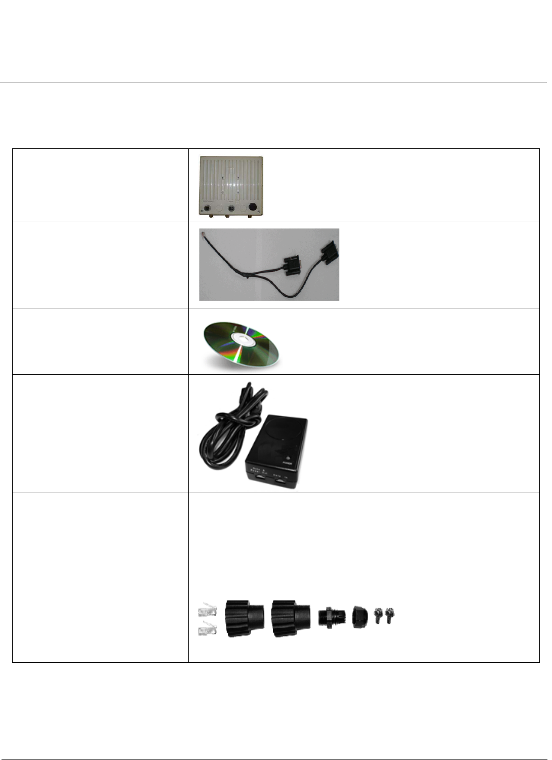
Hardware Overview
The MeshMAX 5054 Series is an full-featured outdoor Subscriber Unit (SU) that is for outdoor deployment, that operate
wither using Power-over-Ethernet (PoE) with the combination DC power supply/injector provided or directly from a 100-
240VAC power source (AC cable provided separately.
The unit is designed for desk-, wall-, or ceiling mounting. It is powered either through DC power or through Power-Over-
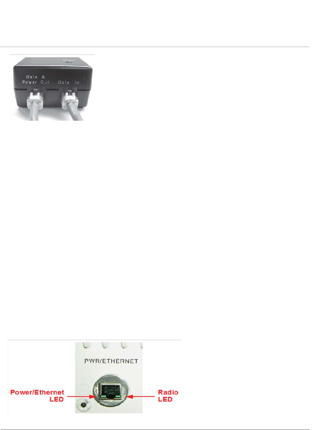
Ethernet (see Power-over-Ethernet), and is equipped with the following connectors and controls:
•Power/Ethernet port: used for Ethernet connection and Power-over-Ethernet (PoE) using the supplied power
injector.
•Serial Connection: used for entering commands in the Command Line Interface (CLI).
•LED Indicator(s): dual LEDs used used to indicate the power and operational states of the unit.
•AC Power Unit: enables direct power from external AC power source.
•External Antenna Connectors (three): one for 2.4 GHz operation for client access, one for 5 GHz for Mesh
operations and one 5 GHz for Subscriber operation.
•Grounding Screws (two)
Figure 2-1 MeshMAX 5054 Unit
Installation and Initialization MeshMAX 5054 Series User Guide
20
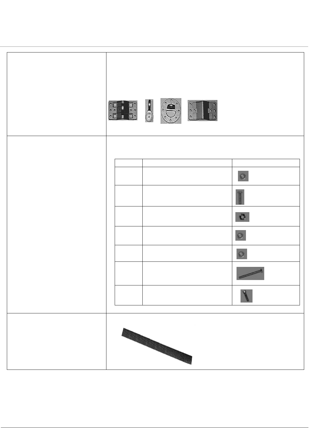
Package Contents
Each shipment includes the items in the following table. Verify that you have recevied all parts of the shipment.
NOTE: Unless listed here, cables are not included with the unit.
MeshMAX 5054 Unit
Y-Cable
Installation CD (1ea.)
Power Injector and Cord (1ea.)
Cable Termination Kit Kit includes:
a. RJ45 connectors (2)
b. Sealing caps (2)
c. Lock nut
d. Sealing nut
e. Grounding screws (2)
A B C D E
Installation and Initialization MeshMAX 5054 Series User Guide
21
Mounting Kit Kit includes the following:
Mounting clamp for walls/pole
Extension arm
Mounting plate to enclosure
Mounting clamp for pole mounting
A B C D
Mounting Hardware The following mounting hardware is included with mounting kit:
Rubber Tape Strip
Qty. Description
6 ea Plain washer # 5/16
2 ea Hex cap screw NC 5/16-18 x 35
2 ea Nut NC 5/16-18
4 ea Helical spring loack washer # 1/4
4 ea Helical speing lock washer # 5/16
2 ea Hex cap screw NC 5/16-18 x 80
4 ea 68764, Screw, Machine, Pan,
Phillips, 1/4” - 20, 5/8” L

Installation and Initialization MeshMAX 5054 Series User Guide
22
Installation Procedure
Step 1: Choose a Location
To make optimal use of the unit, you must find a suitable location for the hardware. The range of the radio unit largely
depends upon the position of the antenna. Proxim recommends you do a site survey, observing the following
requirements, before mounting the hardware.
• The location must allow easy disconnection of power to the radio if necessary.
• Air must be able to flow freely around the hardware.
• The radio unit must be kept away from vibration and excessive heat.
• The installation must conform to local regulations at all times.
The unit is designed to directly mount to a pole or wall. Using the supplied mounting clamps and hardware, you can
mount the unit to a 1.25 inch to 4.5- inch pole (outside diameter). Using just one of the mounting clamps brackets, you
can mount it to a wall or other flat surface.
CAUTION: Proxim recommends the use of a lightning arrestor at the building ingress point. You can purchase the
Proxim Lightning Protector; see the documentation that comes with the Lightning Protector for more
information and installation instructions.
Step 2: Unpack the Shipping Box
1. Unpack the unit and accessories from the shipping box.
2. Note the Ethernet and wireless MAC addresses of the unit, as well as the serial number. The serial number is
required to obtain support from Proxim. Keep this information in a safe place.
Step 3: Assemble the Cable
Use the Cable Termination Kit to assemble the cable. You will be attaching an outdoor-rated 24 AWG CAT5 cable
(diameter .114 to .250 inches/2.9 to 6.4 mm) (not provided) to the Power-over-Ethernet port on the back of the unit
and weatherproofing the assembly later in the installation procedure. First, you must construct the cable and
assemble the weatherproofing cable covers as described in the following steps. Proxim greatly simplifies this
assembly process by offering pre-assembled CAT5 cable kits in 25m, 50m, and 75m lengths (part numbers
69819, 69820, and 69821, respectively).
1. Slide the sealing nut (A) over the bare end of the CAT5 cable.
2. Slide the lock nut (B) over the bare end of the CAT5 cable.
3. Slide the sealing cap (C) over the bare end of the CAT5 cable. Make sure the red rubber gasket is inside the cap.
4. Apply two wraps of 0.5” wide Teflon tape (not supplied with unit) around the threads of the lock nut (B) that will go
inside the sealing cap.
5. Thread the lock nut (B) onto the sealing cap (C), and hand tighten.
6. Terminate the RJ45 connectors (D) to both ends of the CAT5 cable; test for proper wiring (using a straight-through
cable).
7. There are two DB9 connectors that connect to RJ11. The long one connects to Mesh and Access Point module
and the short one to the Subscriber module.
NOTE: The cable must feed through all parts of the weatherproof cap before the RJ45 is crimped on the outdoor
Ethernet cable. The cable between the power injector and the unit must be a straightthrough Ethernet cable
(without crossover). Due to variance in CAT5 cable diameter, termination techniques of the installer, and the
application of proper tightness of the connectors, it is strongly recommended that all cable connectors are
secured by external weatherproofing. This process will be described in Step 10: Weatherproof the Connectors.
Installation and Initialization MeshMAX 5054 Series User Guide
23
Step 4: Assemble Mounting Hardware
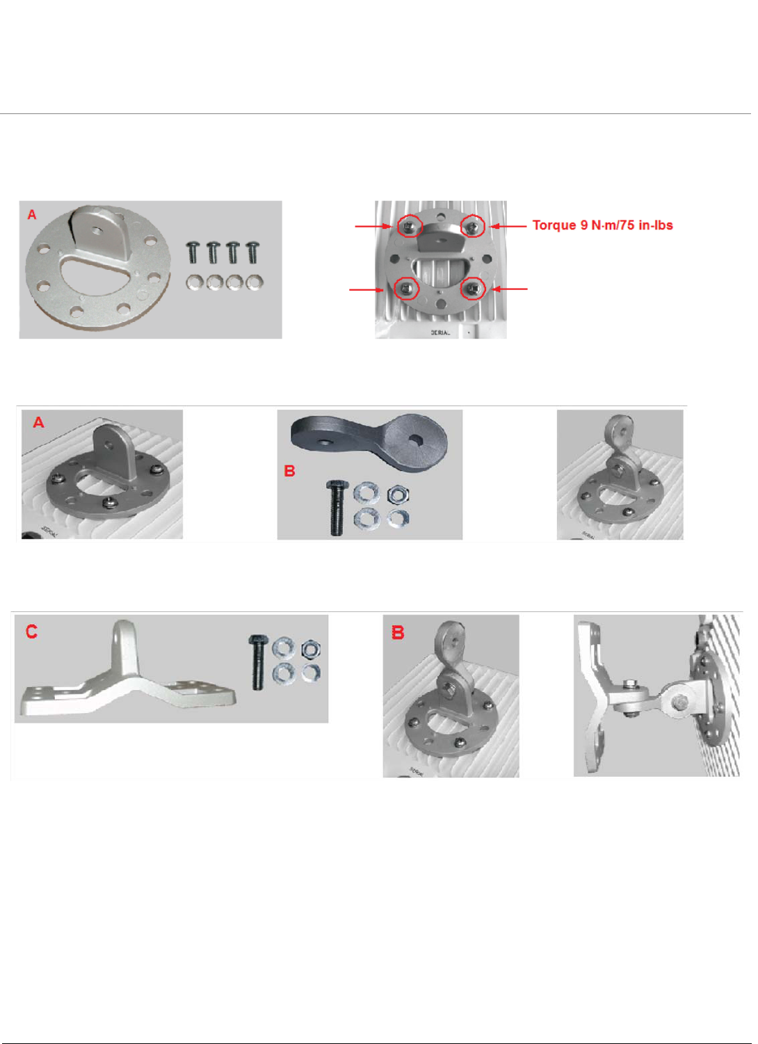
1. Attach the mounting plate (A) using the provided screws and washers (Torque 9 N·m/75 in-lbs)
2. Attach the extension arm (B) to mounting piece (A) with the screw, nut, and washers.
3. Attach the mounting bracket (C) to extension arm (B) with the screw, nut, and washers provided.
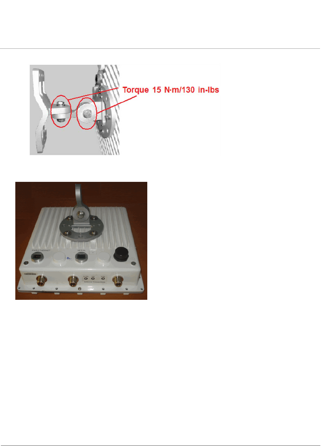
4. Tighten assembly (Torque 15 N·m/130 in-lbs).
Installation and Initialization MeshMAX 5054 Series User Guide
24
The following figure shows the full assembly attached to the unit
Step 5: Mount the Unit
IMPORTANT! If the unit is going to be used as part of a Mesh network, you will need to perform initial
configuration of the parameters mentioned in the Prerequisites section of this MeshMAX 5054 User
Guide before you mount the unit. See the User Guide for more information on configuring these
parameters.
CAUTION: To ensure that water does not gather around the antenna connectors, mount the unit with the antenna
connectors facing downward.
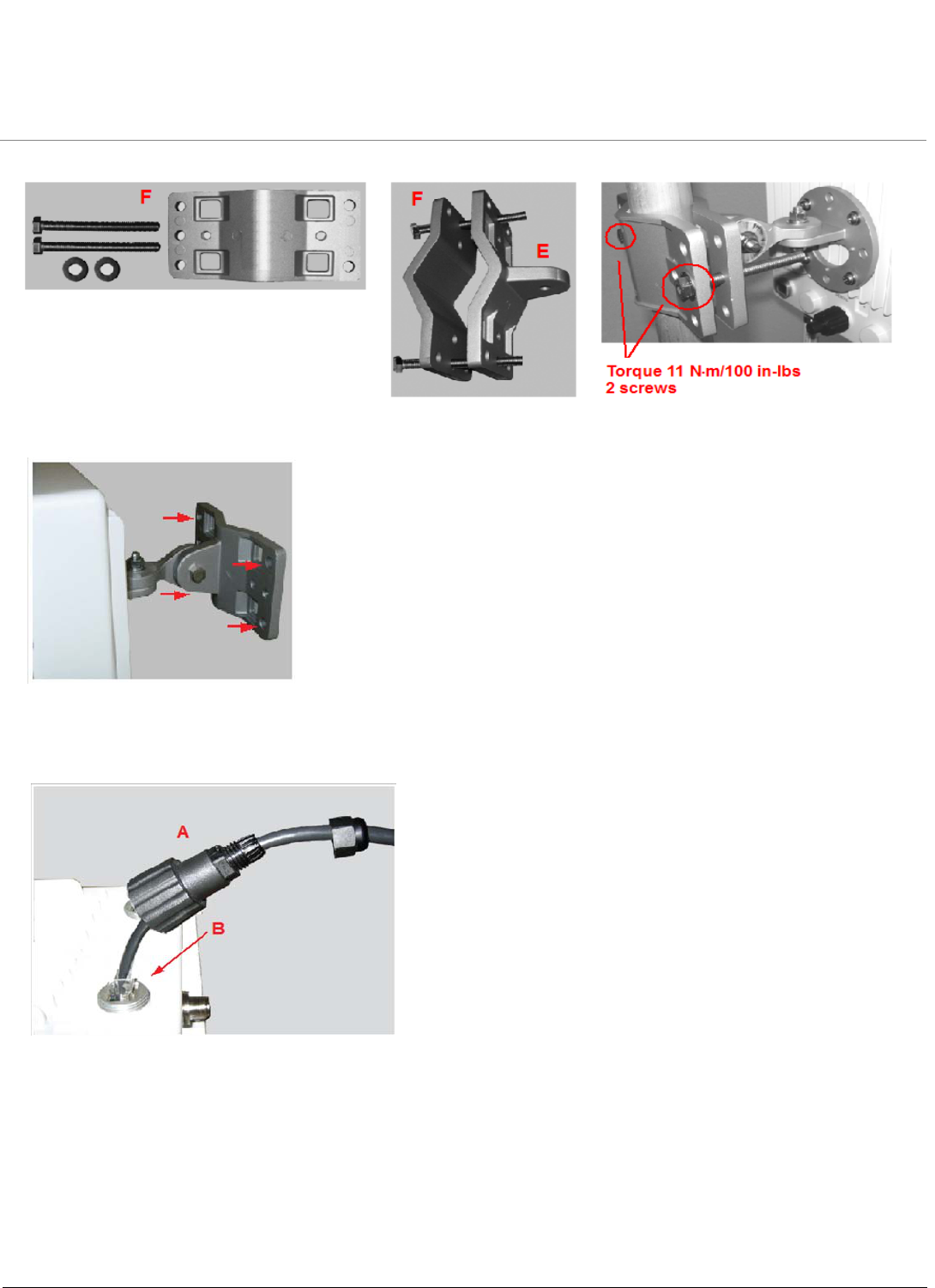
1. To pole-mount, insert the provided screws through bracket F. Fasten around the pole to bracket E and secure
(Torque 11 N.m/100 in-lbs).
Installation and Initialization MeshMAX 5054 Series User Guide
25
2. To wall-mount the unit, mount bracket (E) to the wall using 4 screws (not provided), as shown.
Step 6: Plug in the Cables
1. Plug one end of the CAT5 cable (A) into the RJ45 jack of the unit (B).
2. Connect the free end of the CAT5 cable to the “Data and Power Out” port on the power injector.
Installation and Initialization MeshMAX 5054 Series User Guide
26
3. To connect the unit through a hub or a switch to a PC, connect a straightthrough Ethernet cable between the
network interface card in the PC and the hub, and between the hub and the RJ45 “Data In” port on the PoE
adapter.
To connect the unit directly to a PC, connect a cross-over Ethernet cable between the network interface card in the
PC and the RJ45 “Data In” port on the power injector.
If you are connecting the PC directly to the unit, use a crossover Ethernet cable between the network interface
card in the PC and the RJ45 “Data In” port on the power injector.
Step 7: Power on the Unit
The power injector provides Power-over-Ethernet (PoE), supplying electricity and wired connectivity to the unit
over a single 24 AWG CAT5 (diameter .114 to .250 inches/2.9 to 6.4 mm). The unit is not 802.3af-compatible.
Always use the supplied power injector to ensure that the unit is powered properly. Note that the Active Ethernet
module provides +48 VDC over a standard CAT5 Ethernet cable.
Once you have connected the power injector to the Ethernet cabling and plugged the power injector cord into an
AC outlet, the unit is powered on. There is no ON/OFF switch on the unit. To remove power, unplug the AC cord
from the AC outlet or disconnect the RJ45 connector from the “Data and Power Out” port on the power injector.
Press the Reload button (on the side of the power injector) for five seconds during power-up remotely resets the
Mesh radios to their factory default settings. You will need to use the end of a pin or paperclip to depress the
button.
WARNING: To avoid damaging your router/switch, do not connect the RJ45 port labeled either “Data & Power
Out” from the power injector to your router/switch.
Step 8: View LEDs
The LEDs are present at the unit’s Ethernet connector; unscrew the watertight cap if necessary to view the LEDs.
NOTE: Make sure the domed sealing nut is loose before unscrewing the cap or the Ethernet cable may be twisted and
damaged.
Installation and Initialization MeshMAX 5054 Series User Guide
27
When the unit is powered on, it performs startup diagnostics. When startup is complete, the LEDs show the unit’s
operational state, as follows:
Step 9: Tighten the Cables
1. Apply two wraps of Teflon tape around the threads of the unit’s RJ45 jack (A) in a clockwise direction.
2. Make sure that the red rubber gasket is still seated in the sealing cap of the sealing cap/lock nut assembly (B).
3. Slide the sealing cap/lock nut assembly (B) over the RJ45 jack (A) and thread onto enclosure. Hand tighten first,
then use a pipe wrench or similar tool to tighten one more quarter turn.
CAUTION: Do not over-tighten!
4. Tighten the lock nut (C) (Torque 4 N.m/35 in-lbs).
5. Thread the sealing nut (D) onto the sealing cap/lock nut assembly (B) and tighten (Torque 3 N.m/25 in-lbs).
CAUTION: The lock nut (C) on the sealing cap/lock nut assembly (B) must be fully tightened over the RJ45 connector
before the sealing nut (D) is fully tightened. Otherwise, the Ethernet cable may twist and damage.
Step 10: Weatherproof the Connectors
After you have fully assembled and tightened the cable, use the provided self-fusing, rubber-based tape strip and
electrical tape (not provided; Proxim recommends Scotch™ Super 33+ Vinyl Electrical Tape) to seal the connection, as
follows.
1. Remove the film liner from the rubber-based tape strip, and stretch the tape until it is approximately half of its
original width. This activates the self-fusing action of the tape, which will set up over time to create a single,
waterproof mass.
LED State Power/Ethernet LED Radio LED
Blinking Green Power is on, unit is booting up,
Ethernet link is down.
Mesh radios are being
initialized.
Steady Green Power is on, Ethernet link is up. Mesh radios are being
operational.
Installation and Initialization MeshMAX 5054 Series User Guide
28
2. Stretch and wrap the tape around the connector tightly, starting below the connector cap and against the unit and
wrapping in a clockwise direction. Wrap the tape once around the base of the connector cap (A). Continue to wrap
the tape spirally around the connector in a clockwise direction, maintaining a 50% width overlap (B). Continue
wrapping the tape spirally upward (C) until the tape extends onto the cable and you have used the entire length of
tape. Seal the tape tightly against the connector and the cable (D).
NOTE: Be sure to wrap the tape in a clockwise direction; wrapping the tape in a counterclockwise direction may loosen
up the connector.
3. In the same manner as described in Step 2 above, apply a layer of black electrical tape (not provided) over the
rubber-based tape for further protection. Make sure the electrical tape also extends beyond the rubberbased tape
to seal it.
4. Repeat the weatherproofing procedure for other connectors as appropriate.
Step 11: Align the Antenna
Antenna Alignment Display (AAD) provides a measurement of signal quality in an easy-to-interpret manner - a numeric
printed signal value at the CLI amd serial ports. The SNR is numerically displayed on the CLI serial port by two decimal
charaters representing a number from 00 to 99. On the serial port, AAD is enabled by default after booting.
To start the display, you must enable AAD and a wireless link must be established between the BSU and the SU. Aiming
is complete if moving in any direction results in a falling SNR value.
Antenna alignment commands
The following CLI commands are used to initiate and stop the antenna alignment process. After the process has been
successfully initiated, the CLI displays the current-local/current-remote/average SNR values (in 500 ms intervals) to
indicate the link quality.

Installation and Initialization MeshMAX 5054 Series User Guide
29
Set aad enable local
Enables display of the local SNR (the SNR as measured by the receiver at the far end).
Set aad enable remote
Enables display of the remote SNR (the SNR as measured by the receiver at the far end).
Set aad enable average
Enables display of the remote SNR (the average of local and remote SNR).
Set aad disable
Disables Antenna Alignment Display (Ctrl-C also disables AAD).
Step 12: Install Documentation and Software
To install the documentation and software on a computer or network:
1. Place the installation CD in a CD-ROM drive. The installer normally starts automatically. (If the installation program
does not start automatically, click setup.exe on the installation CD).
2. Follow the instructions displayed on the installer windows.

Installation and Initialization MeshMAX 5054 Series User Guide
30
Reboot and Reset Functionality for MeshMAX
Press the Reload button (on the side of the power injector) to intiate the Reload/Reset functionality. You may have to use
the end of a pin or paperclip to press the button.
Reboot and Reset Functionality for Mesh and Access Point Module
If the Reload button is pressed for 5 to 10 seconds and then released, then Mesh and Access Point module moves to the
bootloader state. If Reload button is pressed beyond 10 seconds, then the Mesh and Access Point module’s Reload
functionality is ignored.
Reboot and Reset Functionality for Subscriber Module
If the Reload button is pressed for 20 seconds and above, then the Subscriber module moves to reload state. If the
Reload button is pressed for 10 to 20 sconds and released, then none of the operation is performed and the Reload
button is aborted.
NOTE: Bootloader will display allevents to the serial console, which will guide user to perform the Reload functionality.
Installation and Initialization MeshMAX 5054 Series User Guide
31
Unit Initialization
The MeshMAX unit has two modules: Subscriber module and Mesh and Access Point module. To initiate the process,
you need to use the Scantool.
Using ScanTool
ScanTool is a software utility that is included on the installation CD-ROM. It is an initial configuration tool that allows you
to find the IP address of an Access Point by referencing the MAC address in a Scan List, or to assign an IP address if one
has not been assigned.
The tool automatically detects the MeshMAX units installed on your network, regardless of IP address, and lets you
configure each unit’s IP settings. In addition, you can set initial device parameters that will allow the Mesh radio to
retrieve a new software image if a valid software image is not installed.
To access the HTTP interface and configure the Mesh unit, the unit must be assigned an IP address that is valid on its
Ethernet network. By default, the Mesh unit is configured to obtain an IP address automatically from a network Dynamic
Host Configuration Protocol (DHCP) server during boot-up. If your network contains a DHCP server, you can run
ScanTool to find out what IP address the Mesh radios have been assigned. If your network does not contain a DHCP
server, the IP address for the Mesh radios defaults to 169.254.128.132. In this case, you can use ScanTool to assign the
unit a static IP address that is valid on your network.
Scan Tool Instructions
1. Power up, reboot, or reset the unit.
2. Double-click the ScanTool icon on the Windows desktop to launch the program. If the icon is not on your desktop, click
Start > All Programs > Proxim > MeshMAX 5054 > ScanTool.
If your computer has more than one network adapter installed, you will be prompted to select the adapter that you want
ScanTool to use before the Scan List appears. You can use either an Ethernet or wireless adaptor.
NOTE: If prompted, select an adapter and click OK. You can change your adapter setting at any time by clicking the
Select Adapter button on the Scan List screen. ScanTool scans the subnet and displays all detected units. The
ScanTool’s Scan List screen appears, as shown in the following example.
If your unit does not appear in the Scan List, click the Rescan button to update the display. If the unit still does not appear
in the list, see the Troubleshooting chapter in the MeshMAX 5054 User Guide for suggestions. Note that after rebooting
an Access Point, it may take up to five minutes for the unit to appear in the Scan List.
3. Do one of the following:
– If the Mesh radio has been assigned an IP address by a DHCP server on the network:
a. a. Highlight the entry for the unit you want to configure.
b. Click the Change button. The Change screen appears (see below).
c. Click on the Web Configuration button at the bottom of the change screen.
d. Proceed to the Logging In section, below.
Installation and Initialization MeshMAX 5054 Series User Guide
32
– If the Mesh radio has not been assigned an IP address (in other words, the unit is using its default IP address,
169.254.128.132), follow these steps to assign it a static IP address that is valid on your network:
a. Highlight the entry for the unit you want to configure.
b. Click the Change button. The Change screen appears.
c. Set IP Address Type to Static.
d. Enter a static IP Address for the Mesh radio in the field provided. You must assign the unit a unique address
that is valid on your IP subnet.
e. Enter your network’s Subnet Mask.
f. Enter your network’s Gateway IP Address.
g. Enter the SNMP read/write password in the Read/Write Password field. For new units, the default password is
public.
h. Click OK to save your changes.
i. The Access Point will need to reboot to apply any changes you made. When the reboot message appears,
click OK to reboot the device and return to the Scan List screen.
j. After allowing sufficient time for the device to reboot, click Rescan to verify that your changes have been
applied.
k. Click the Change button to return to the Change screen.
l. Click the Web Configuration button at the bottom of the Change screen.
m. Proceed to the Logging In section, below.
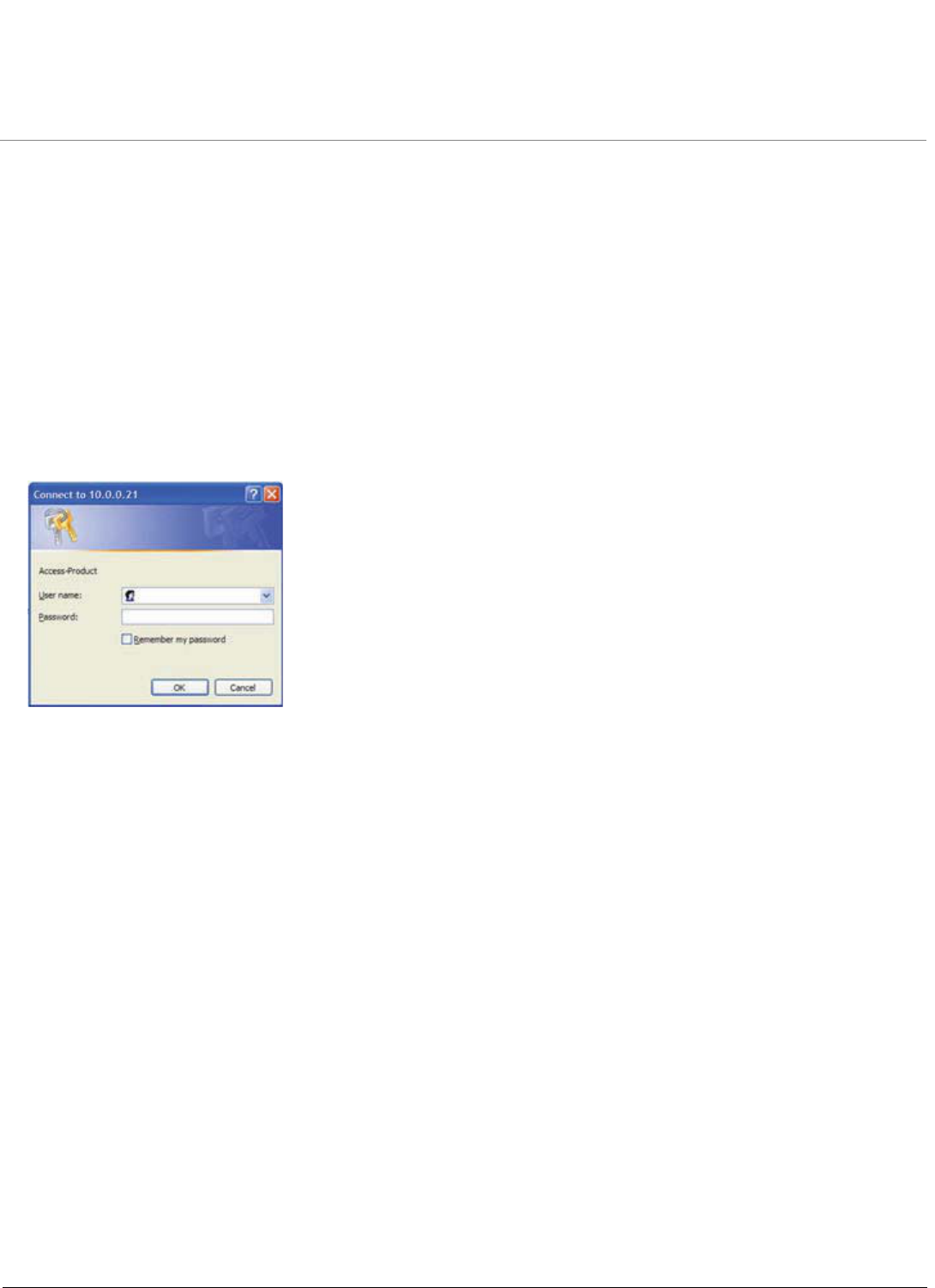
Installation and Initialization MeshMAX 5054 Series User Guide
33
Mesh Initialization
Logging In
Once the Mesh radio has a valid IP Address, you may use your web browser to monitor and configure the Mesh radio.
(To configure and monitor using the command line interface, see the MeshMAX 5054 User Guide.)
1. Open a Web browser on a network computer.
2. If necessary, disable the browser’s Internet proxy settings.
3. Enter the Access Point’s IP address in the browser’s Address field and press Enter or Go. This is either the dynamic
IP address assigned by a network DHCP server or the static IP address you manually configured. See the Using
ScanTool section above for information on how to determine the unit’s IP address and manually configure a new IP
address, if necessary.
4. The login screen appears.
5. Enter the HTTP password in the Password field. Leave the User Name field blank. For new units, the default HTTP
password is public. If you are logging on for the first time the Setup Wizard will launch automatically.
NOTE: Setup Wizard will not relaunch on subsequent logins. To force the Setup Wizard to launch upon login, click
Management > Services and choose Enable from the Setup Wizard drop down menu.
6. To configure the Mesh radio using the Setup Wizard, see Using the Setup Wizard, below. To configure the radio
without using the Setup Wizard, click Exit. Upon clicking Exit, the System Status screen will appear. See the
“Advanced Configuration” chapter in the MeshMAX 5054 User Guide for configuration instructions.
Using the Setup Wizard
The Setup Wizard provides step-by-step instructions for how to configure the Access Point’s basic operating parameters,
such as Network Name, IP parameters, system parameters, and management passwords.
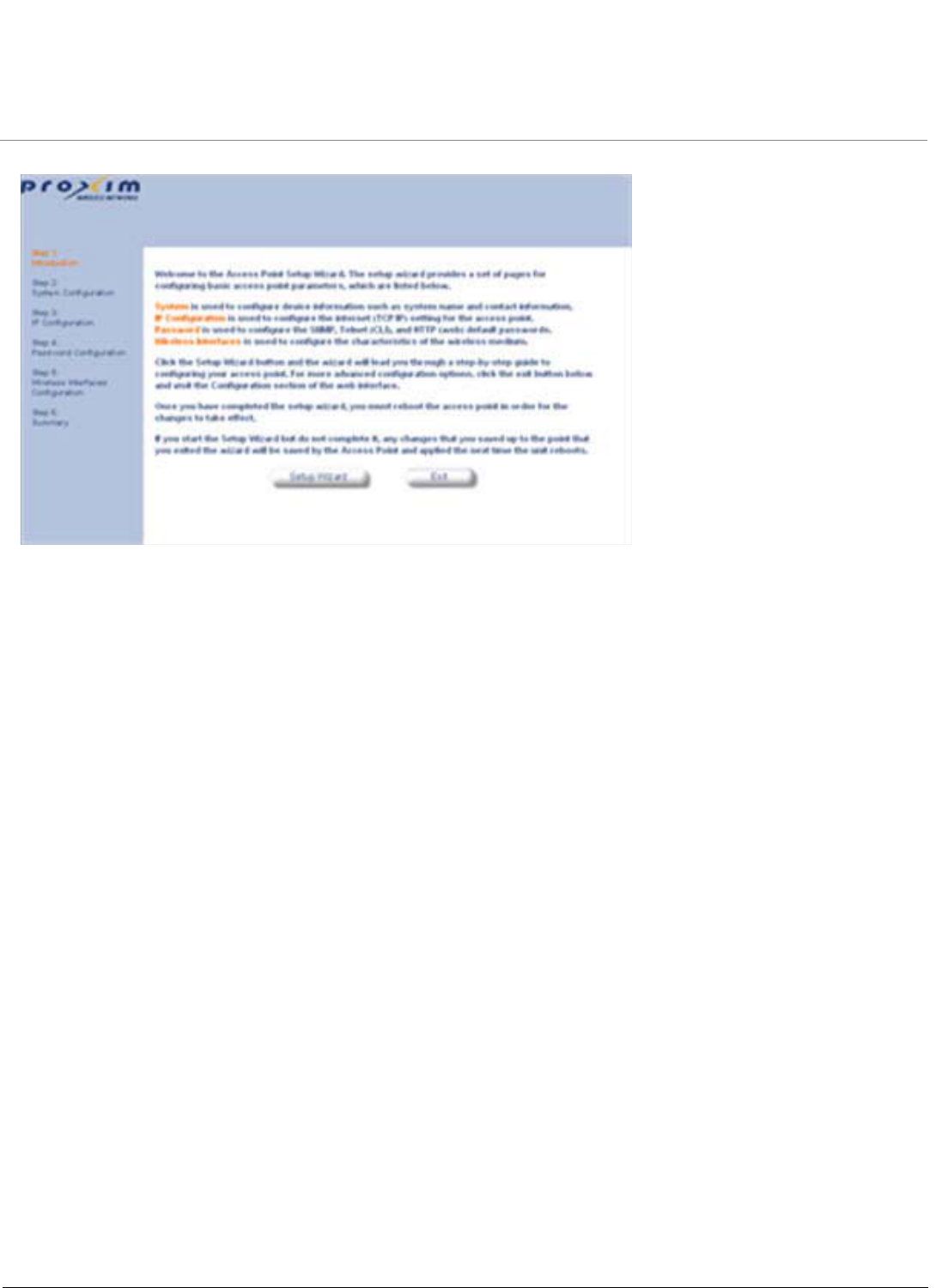
Installation and Initialization MeshMAX 5054 Series User Guide
34
1. Click Setup Wizard to begin. The Setup Wizard supports the following navigation options:
•Save & Next Button: Each Setup Wizard screen has a Save & Next button. Click this button to submit any
changes you made to the unit’s parameters and continue to the next page. The instructions below describe how to
navigate the Setup Wizard using the Save & Next buttons.
•Navigation Panel: The Setup Wizard provides a navigation panel on the left-hand side of the screen. Click the
link that corresponds to the parameters you want to configure to be taken to that particular configuration screen.
Note that clicking a link in the navigation panel will not submit any changes you made to the unit’s configuration on
the current page.
•Exit: To exit from the Setup Wizard at any time, click Step 1: Introduction on the navigation panel, and then click
the Exit button.
CAUTION: If you exit from the Setup Wizard, any changes you submitted (by clicking the Save & Next button) up to that
point will be saved to the unit but will not take effect until it is rebooted.
2. Follow the prompts provided by the Setup Wizard to perform an initial configuration of the Mesh radio. See the
MeshMAX 5054 User Guide for more detailed Setup Wizard instructions and for advanced configuration instructions.
Software Updates
Proxim periodically releases updated software for the MeshMAX 5054 on its support Web site, http://support.proxim.com.
Proxim recommends that you check the Web site for the latest updates after you have installed and initialized the unit.
Download the Software
1. In your web browser, go to http://support.proxim.com.
2. If prompted, create an account to gain access.
NOTE: The Knowledgebase is available to all Web site visitors. First-time users will be asked to create an account to
gain access.
3. Click Search Knowledgebase.
4. In the Search Knowledgebase field, enter 2334.
5. Click Search.
6. Click on the link in the Summary column to access the download page.
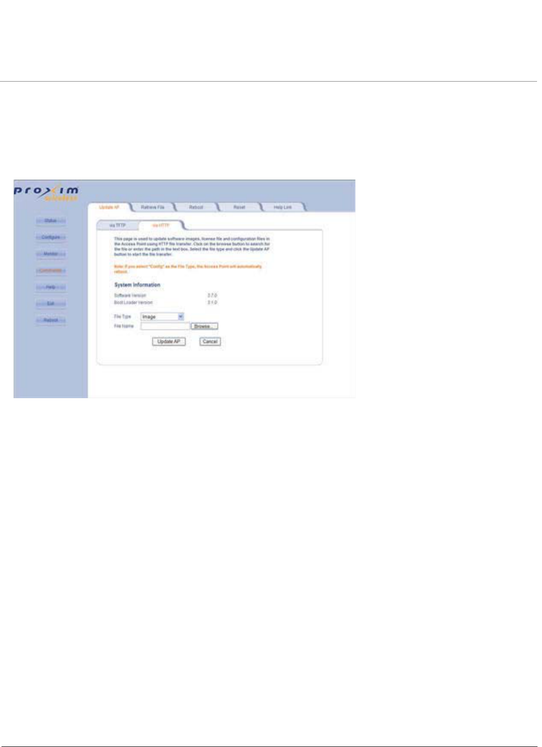
Installation and Initialization MeshMAX 5054 Series User Guide
35
7. Click on the appropriate link to download the software.
Install the Software
1. Enter the Access Point’s IP address in the browser’s Address field and press Enter or Go.
2. Click Commands > Update AP > via HTTP. The Update AP via HTTP screen will be displayed.
3. From the File Type drop-down menu, select Image.
4. Use the Browse button to locate or manually type in the name of the file (including the file extension) you downloaded
from the Proxim Knowledgebase. If typing the file name, you must include the full path and the file extension in the file
name text box.
5. To initiate the HTTP Update operation, click the Update AP button. A warning message advises you that a reboot of
the device will be required for changes to take effect.
6. Click OK to continue with the operation or Cancel to abort the operation.
7. If the operation is unsuccessful, you will receive an error message. See the MeshMAX 5054 User Guide for more
information. If the operation is successful, you will receive a confirmation message.
8. Reboot the Mesh radio as follows:
a. Click Commands > Reboot.
b. Enter 0 in the Time to Reboot field.
c. Click OK.
NOTE: For instructions on downloading the software via a TFTP Server or the CLI Interface, see the MeshMAX 5054
User Guide.

Installation and Initialization MeshMAX 5054 Series User Guide
36
Subscriber Initialization
Connecting to the module requires either:
• A direct physical connection with an Ethernet cable or with a serial RS-32 cable
• A network connection
Connecting with the Ethernet cable allows you to access the unit through a terminal emulation program, such as
HyperTerminal. (See “HyperTerminal Connection Properties” in the MeshMAX 5054 User Guide.
Setting the IP Address
With ScanTool (a software utility that is included on the product installation CD), you can find out the current IP address of
the unit and, if necessary, change it so that is appropriate for your network.
ScanTool lets you find the IP address of a module by referencing the MAC address in a Scan List, or to assign an IP
address if the correct one has not been assigned. The tool automatically detects the units installed on your network
segment, regardless of IP address, and lets you configure each unit’s IP settings. In addition, you can use ScanTool to
download new software to a unit that does not have a valid software image installed.
To discover and set/change the IP address of the unit:
Run ScanTool on a computer connected to the same LAN subnet as the unit, or a computer directly connected to the
module with a cross-over Ethernet cable. Double-click the ScanTool icon on the Windows desktop to launch the program.
If the icon is not on your desktop, click Start > All Programs > MeshMAX 5054 series > ScanTool.
ScanTool scans the subnet and displays the module it finds in the main window. If necessary, click Rescan to re-scan the
subnet and update the display. You can assign a new IP address to one module, even if more than one module has the
same (default) IP address 10.0.0.1, but the new IP address must be unique to allow the use of the management
interfaces.
Select the module for which you want to set the IP address and click Change. The Change dialog window is displayed.
To set the IP address manually, ensure that Static is selected as the IP Address Type and fill in the IP Address and
Subnet Mask suitable for the LAN subnet to which the uni is connected.
To set the IP address dynamically, ensure that Dynamic is selected as the IP Address Type. The module will request its
IP address from a DHCP server on your network.
Enter the Read/Write Password (the default value is public) and click OK to confirm your changes. The respective module
reboots to make the effective.
Accessing the Web Browser
To access the module with a Web Browser:
Start a Web browser and enter the IP address of the module in the Address box (for example, http://10.0.0.1).
A login window is displayed. Do not fill in the User name; enter only the default password public.
Upon successful login, the System Status window is displayed.
Accessing the Command Line Interface
The CLI is accessible through the Serial RS-232 cable connected through the network, or with a cross-over Ethernet
cable between the computer and the module’s serial port.
Ethernet Port
To use the CLI through the Ethernet port, you must have a telnet program, and the module’s IP address.
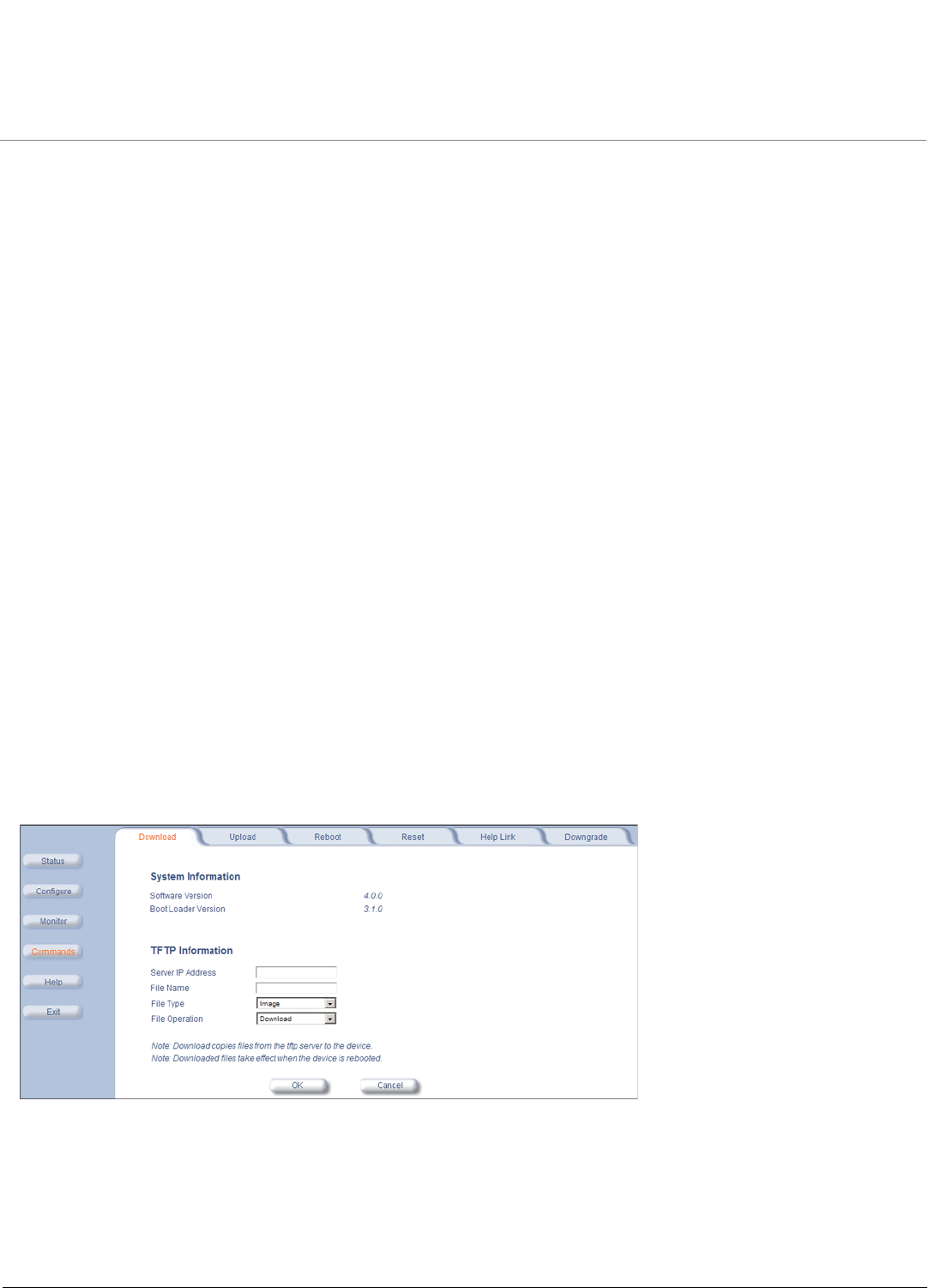
Installation and Initialization MeshMAX 5054 Series User Guide
37
To access the unit through Ethernet on a Windows PC:
Open a DOS command window: from the Windows Start menu, Select Run; enter cmd.
In the DOS window displayed, enter telnet and IP address (for example, telnet 10.0.0.1) and type <enter>. You will be
prompted for your password.
Enter the password (the default is public).
Software Updates
Proxim periodically releases updated software for the MeshMAX 5054 on its support Web site, http://support.proxim.com.
Proxim recommends that you check the Web site for the latest updates after you have installed and initialized the unit.
Download the Software
1. In your web browser, go to http://support.proxim.com.
2. If prompted, create an account to gain access.
NOTE: The Knowledgebase is available to all Web site visitors. First-time users will be asked to create an account to
gain access.
3. Click Search Knowledgebase.
4. In the Search Knowledgebase field, enter 2334.
5. Click Search.
6. Click on the link in the Summary column to access the download page.
7. Click on the appropriate link to download the software.
Install the Software
1. Click Commands > Download to download configuration, image and license files to the unit via a TFTP server (see
TFTP Server Setup for information about the SolarWinds TFTP server software located on your product installation
CD).
2. The following parameters may be configured or viewed:
•Server IP address: Enter the TFTP Server IP address.
•File Name: Enter the name of the file to be downloaded. If you are using the SolarWinds TFTP server software
located on your product installation CD, the default directory for downloading files is C:\TFTP-Root.
•File Type: Choose either Config, image, BspBl, or license.
•File Operation: Choose either Download or Download and Reboot.

Installation and Initialization MeshMAX 5054 Series User Guide
38
3. Click OK to start the download.

39
MeshMAX 5054 Series User Guide
3
System Overview of Subscriber Module
This chapter has information about the following:
Changing Basic Configuration Information
–Country and Related Settings
–Dynamic Frequency Selection (DFS)
–Transmit Power Control
•SU Registration
•Dynamic Data Rate Selection (DDRS)
•Virtual Local Area Networks (VLANs)
•Quality of Service (QoS)
–Concepts and Definitions
—Packet Identification Rule (PIR)
—Service Flow Class (SFC)
—QoS Class
Changing Basic Configuration Information
To view or change basic system information, click the Configure button on the left side of the Web interface window,
then click the System tab. See System Parameters for detailed information about the fields and selections in this
window.
NOTE: System Name by default contains the actual model number. The following screenshot is for information only.
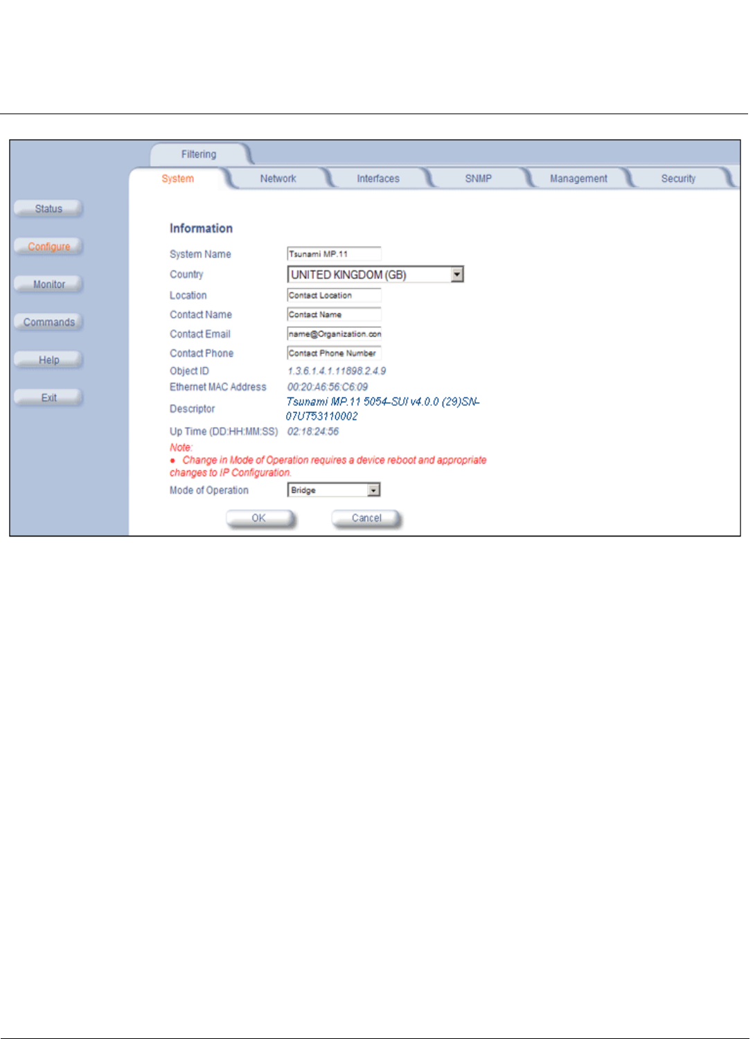
System Overview of Subscriber Module MeshMAX 5054 Series User Guide
Changing Basic Configuration Information
40
Country and Related Settings
The unit’s Configure System window provides a selectable Country field that automatically provides the allowed
bandwidth and frequencies for the selected country.
Units sold only in the United States are pre-configured to scan and display only the outdoor frequencies permitted by the
FCC. No other Country can be configured. Units sold outside of the United States support the selection of a Country by
the professional installer.
NOTE: Non-US installers should not add an antenna system until the Country is selected, the unit is rebooted, and the
proper power level is configured. The output power level of the final channel selected by DFS scan can be found
in the Event Log.
The Dynamic Frequency Selection (DFS) feature is enabled automatically when you choose a country and band that
require it. The Transmit Power Control (TPC) feature is always available.
Click Configure > System; then select the appropriate country for your regulatory domain from the Country drop-down
box.
Continue configuring settings as desired; then click Commands>Reboot tab to save and activate the settings.
Alternatively, if you want to save the configuration settings to the flash memory but not activate the settings, use the save
config CLI command.
Dynamic Frequency Selection (DFS)
The subscriber module supports Dynamic Frequency Selection (DFS) for FCC, IC, and ETSI regulatory domains per
FCC Part 15 Rules for U-NII devices, IC RSS-210, and ETSI EN 301-893 and 302-502 regulations, respectively. These
rules and regulations require that 802.11a devices use DFS to prevent interference with radar systems and other devices
that already occupy the 5 GHz band.

System Overview of Subscriber Module MeshMAX 5054 Series User Guide
Changing Basic Configuration Information
41
During boot-up, the unit scans the available frequency and selects the best channel. If the unit subsequently detects
interference on its channel, it rescans to find a better channel. Upon finding a new channel, the unit is required to wait 60
seconds to ensure that the channel is not busy or occupied by radar, and then commences normal operation. (In Canada,
if the channel was previously blacklisted, the unit scans for 600 seconds before commencing normal operation if the
selected channel frequency is in the 5600 - 5650 MHz range).
If you are using the unit in a country and band that require DFS, keep in mind the following:
• DFS is not a configurable parameter; it is always enabled and cannot be disabled.
• You cannot manually select the device’s operating channel; you must let the unit select the channel. You may make
channels unavailable by manually “blacklisting” them and preventing those channels being selected, in accordance
with local regulations or interference. You can also display the Channel Blacklist Table to view the channels that have
been blacklisted.
• In compliance with FCC regulations, the unit uses ATPC (Automatic Transmit Power Control) to automatically adapt
transmit power when the quality of the link is more than sufficient to maintain a good communication with reduced
transmit power. See Transmit Power Control for more information.
Dynamic Frequency Selection (DFS) is enabled automatically based upon the country and band you select. You can tell
DFS is in use because the Frequency Channel field on the Interfaces page displays only the DFS-selected frequency.
DFS scans all available frequencies, starting with the DFS preferred channel (when configured) and skipping blacklisted
channels, to select the operating frequency automatically.
A country/band selection with DFS enabled causes the Base Station to come up in scan mode. It scans the available
frequencies and channels to avoid radar and selects a channel with the least interference.
NOTE: Scanning is performed only on the frequencies allowed in the regulatory domain of the country/band selected
when it is required for radar detection and avoidance.
The SU also comes up in scan mode to scan all available frequencies to find a BSU with which it can register. Scanning
may take several minutes. After establishing a wireless link, the wireless LED stops flashing and continues to shine
green.
NOTE: Because DFS may need to scan for radar on multiple channels, you must allow a sufficient amount of time for the
units to start up. This is considerably longer than when the unit is not using DFS. This is expected behavior.
Startup time is within four minutes if no radar is detected, but up to one minute is added for every selected
channel that results in radar detection.
DFS is required for three purposes:
1. Radar avoidance both at startup and while operational. To meet these requirements, the BSU scans available
frequencies at startup. If a DFS-enabled channel is busy or occupied with radar, the system will blacklist the channel
for a period of 30 minutes in accordance with FCC, IC, and ETSI regulations. Once fully operational on a frequency,
the BSU actively monitors the occupied frequency. If interference is detected, the BSU blacklists the channel, logs a
message and rescans to find a new frequency that is not busy and is free of radar interference.
Radar detection is performed only by the BSU and not by the SU. When an SU is set to a country/band in which DFS
is used, it scans all available channels upon startup looking for a BSU that best matches its connection criteria (such
as Base Station System Name,Network Name, and Shared Secret). The SU connects to the BSU automatically on
whatever frequency the BSU has selected. Because of this procedure, it is best to set up the BSU and have it fully
operational before installing the SU, although this is not required. If a BSU rescans because of radar interference, the
SU loses its wireless link. The SU waits 30 seconds (when the Mobility feature is enabled, the SU starts scanning for
a BSU instantly rather than waiting 30 seconds); if it finds that it could not receive the BSU in this amount of time, it
rescans the available frequencies for an available BSU.
2. Guarantee the efficient use of available frequencies by all devices in a certain area. To meet this requirement, the
BSU scans each available frequency upon startup and selects a frequency based upon the least amount of noise and
interference detected. This lets multiple devices operate in the same area with limited interference. This procedure is

System Overview of Subscriber Module MeshMAX 5054 Series User Guide
SU Registration
42
done only at startup; if another UNII device comes up on the same frequency, the BSU does not detect this or rescan
because of it. It is expected that other devices using these frequencies also are in compliance with country/band
regulations, so this should not happen.
3. Uniform Channel Spreading. To meet this requirement, the MP.11-R randomly selects operating channel from the
available channels with least interference. If the DFS Preferred Channel is configured, the unit begins by scanning
that channel. If no interference is detected, the unit makes this channel operational. If the channel is busy or occupied
by radar, the unit blacklists that channel and scans other available channels for the one with least interference. This
implements the Uniform Channel Spreading requirement by either automatically selecting the channel with least
interference or allowing the installer to manually select a channel with least interference from a channel plan.
Transmit Power Control
Transmit Power Control is a manual configuration selection to reduce the unit’s output power. The maximum output
power level for the operating frequency can be found in the event log of the unit’s embedded software.
ATPC (Automatic Transmit Power Control) is a feature to automatically adapt transmit power when the quality of the link
is more than sufficient to maintain a good communication with reduced transmit power. This feature is required for FCC
DFS. It works by monitoring the quality of the link and reducing the output power of the radio by up to 6 dB when good link
quality can still be achieved. When link quality reduces, the output power is automatically increased up to the original
power level to maintain a good link. For a full discussion of DFS, see Dynamic Frequency Selection (DFS) above.
By default, the unit lets you transmit at the maximum output power that the radio can sustain for data rate and frequency
selected. However, with Transmit Power Control (TPC), you can adjust the output power of the unit to a lower level in
order to reduce interference to neighboring devices or to use a higher gain antenna without violating the maximum
radiated output power allowed for your country/band. Also, some countries that require DFS also require the transmit
power to be set to a 6 dB lower value than the maximum allowed EIRP when link quality permits, as part of the DFS
requirements.
NOTE: When the system is set to transmit at the maximum power, professional installers must ensure that the maximum
EIRP limit is not exceeded. To achieve this, they may have to add attenuation between the device and the
antenna when a high gain antenna is used.
NOTE: You can see your unit’s current output power for the selected frequency in the event log. The event log shows the
selected power for all data rates, so you must look up the relevant data rate to determine the actual power level.
NOTE: This feature only lets you decrease your output power; you cannot increase your output power beyond the
maximum the radio allows for your frequency and data rate.
See System Parameters to configure Country. See Interface Parameters to configure Transmit Power Control.
SU Registration
The list of parameters you must configure for registration of the SU on a BSU are:
• Network Name
• Base Station System Name (when used; otherwise, leave blank)
•Network Secret
• Encryption (when used)
• Frequency Channel (when available)
See System Parameters to see the description of these fields and to configure them.
NOTES:
•The frequency channel must be the same for the BSU and the SU in order to register the SU when roaming is
not enabled and DFS is not required.

System Overview of Subscriber Module MeshMAX 5054 Series User Guide
Dynamic Data Rate Selection (DDRS)
43
•Channel Bandwidth and Turbo mode (when available) must be the same for the BSU and SU in order to register
the SU.
•Roaming will automatically select a channel on the SU corresponding to the BSU channel. Roaming is the
procedure in which an SU terminates the session with the current BSU and starts the registration procedure with
another BSU when it finds the quality of the other BSU to be better.
Dynamic Data Rate Selection (DDRS)
NOTE: DDRS is configured on the BSU. See the Tsunami MP.11-R Installation and Management Guide for more
information.
The WORP Dynamic Data Rate Selection (DDRS) lets the BSU and SUs monitor the remote average signal-to-noise
ratio (SNR) and the number of retransmissions between the BSU and SUs and adjust the transmission data rate to an
optimal value to provide the best possible throughput according to the current communication conditions and link quality.
With DDRS enabled, a BSU can maintain different transmission data rates to different SUs, optimizing the data rate
based on the link quality of each SU independently.
Both the BSU and the SUs monitor the remote SNR and number of retransmissions. The BSU monitors these values for
each SU that is registered. An SU monitors these values for the BSU. When necessary, based on this information, the
data rate is dynamically adjusted.
Note that DDRS is enabled or disabled on the BSU only. This operation requires the BSU to be rebooted. After rebooting,
the BSU sends a multicast announcement to all SUs to begin the registration process. During registration, an SU is
informed by the BSU whether DDRS is enabled or disabled and it sets its DDRS status accordingly.
Virtual Local Area Networks (VLANs)
NOTE: VLANs are configured on the Base Station Unit. See the Tsunami MP.11-R Installation and Management Guide
for more information.
Virtual Local Area Networks (VLANs) are logical groupings of network hosts. Defined by software settings, other VLAN
members or resources appear (to connected hosts) to be on the same physical segment, no matter where they are
attached on the logical LAN or WAN segment. They simplify allowing traffic to flow between hosts and their
frequently-used or restricted resources according to the VLAN configuration.
Subscriber units are fully VLAN-ready; however, by default, VLAN support is disabled. Before enabling VLAN support,
certain network settings should be configured and network resources such as VLAN-aware switches should be available,
dependent upon the type of configuration.
VLANs are used to conveniently, efficiently, and easily manage your network in the following ways:
• Manage VLAN configuration from a single window
• Define groups
• Reduce broadcast and multicast traffic to unnecessary destinations
• Improve network performance and reduce latency
• Increase security
• Secure network restricts members to resources on their own VLAN
VLAN tagged data is collected and distributed through a unit’s Ethernet interface. The units can communicate across a
VLAN-capable switch that analyzes VLAN-tagged packet headers and directs traffic to the appropriate ports when the
units are working in their Transparent mode.
VLAN features can be managed via:
• The BSU’s Web interface
• The Command Line Interface

System Overview of Subscriber Module MeshMAX 5054 Series User Guide
Virtual Local Area Networks (VLANs)
44
• SNMP (see the MIBs provided on the product CD)
VLAN Modes
Transparent Mode
Transparent mode is available on both the SU and the BSU. This mode is equivalent to NO VLAN support and is the
default mode. It is used when the devices behind the SU and BSU are both VLAN aware and unaware. The SU/BSU
transfers both tagged and untagged frames received on the Ethernet or WORP interface. Both tagged and untagged
management frames can access the device.
Trunk Mode
Trunk mode is available on both the SU and the BSU. It is used when all devices behind the SU and BSU are VLAN
aware. The SU and BSU transfer only tagged frames received on the Ethernet or WORP interface. SU can be accessed
by both tagged and untagged frames. When BSU is in trunk mode, then it can be accessed only by the frmaes that are
tagged with the management VLAN ID.Access Mode.
Access mode is available only on the SU. It is used when the devices behind the SU are VLAN unaware. Frames to and
from the Ethernet interface behind the SU map into only one VLAN segment.
Frames received on the Ethernet interface are tagged with the configured Access VLAN ID before forwarding them to the
WORP interface. Both tagged and untagged management frames can access the device from the WORP interface.
However, only untagged management frames can access the device from the Ethernet Interface.
Mixed Mode
Mixed mode is available on both the SU and the BSU. It is used when the devices behind the SU send both tagged and
untagged data. Frames to and from the Ethernet interface behind the SU can be tagged or untagged.
Tagged frames received on the Ethernet interface are compared against the SU’s trunk table, and only packets whose
VLAN ID matches the trunk table are forwarded. All other packets are dropped. Untagged traffic is forwarded without any
restrictions. If the BSU is in Mixed mode, the SU can be in Trunk, Access, or Mixed mode.
Q-in-Q (VLAN Stacking)
The Q-in-Q mechanism allows Service Providers to maintain customer-assigned VLANs while avoiding interference with
the Service Providers’ VLANs. Using the Q-in-Q mechanism, an Outer VLAN ID and Priority are added to VLAN tagged
packets on top of the existing VLAN ID, such that interference is avoided and traffic is properly routed.
VLAN Forwarding
The VLAN Trunk mode provides a means to configure a list of VLAN IDs in a Trunk VLAN Table. The SU and BSU only
forward frames (between Ethernet and WORP interface) tagged with the VLAN IDs configured in the Trunk VLAN Table.
Up to 256 VLAN IDs can be configured for the BSU and up to 16 VLAN IDs can be configured for the SU (depending
upon the capabilities of your switching equipment).
VLAN Relaying
The VLAN Trunk mode for BSU operation provides an option to enable and disable a VLAN relaying flag; when enabled,
the BSU shall relay frames between SUs on the same BSU having the same VLAN ID.
Management VLAN
The BSU and SU allow the configuration of a separate VLAN ID and priority for SNMP, ICMP, Telnet, and TFTP
management frames for device access.
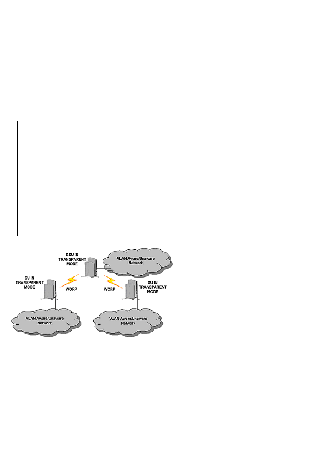
System Overview of Subscriber Module MeshMAX 5054 Series User Guide
Virtual Local Area Networks (VLANs)
45
The management VLAN ID and management VLAN priority may be applied in any mode. The management stations tag
the management frames they send to the BSU or SU with the management VLAN ID configured in the device. The BSU
and SU tag all the management frames from the device with the configured management VLAN and priority.
BSU and SU in Transparent Mode
When the BSU is in Transparent mode, all associated SUs must be in Transparent mode.
How the BSU and SUs function in Transparent mode is described in the following table.
BSU in Trunk Mode and SU in Trunk/Access Mode
When the BSU is in Trunk mode, the associated SUs must be in either Trunk mode or Access mode. When an SU
associates to a BSU that is in Trunk mode, it gets the VLAN mode from the BSU.
How the BSU and SU function in Trunk mode, and the SU in Access mode, is described in the following table.
BSU Function – Transparent Mode SU Function – Transparent Mode
• BSU forwards both tagged and untagged
frames received from the Ethernet interface or
from any of the associated SUs.
• If a valid management VLAN ID is configured,
BSU allows only management frames tagged
with the configured management VLAN ID to
access it.
• If a valid management VLAN ID is configured,
BSU tags all management frames generated
by the BSU with the configured management
VLAN ID and priority.
• If the management VLAN ID is configured as
-1 (untagged), BSU allows only untagged
management frames to access it.
• SU forwards both tagged and untagged frames
received from the Ethernet interface or from
the BSU.
• If a valid management VLAN ID is configured,
SU allows only management frames tagged
with the configured management VLAN ID to
access it.
• If a valid management VLAN ID is configured,
SU tags all management frames generated by
the SU with the configured management VLAN
ID and priority.
• If the management VLAN ID is configured as
-1 (untagged), SU allows only untagged
management frames to access them.
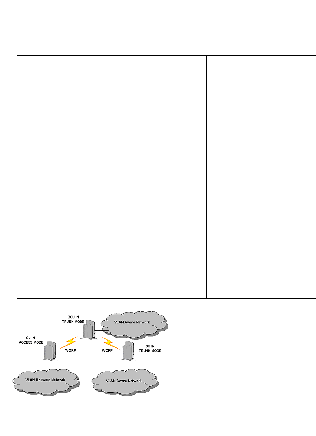
System Overview of Subscriber Module MeshMAX 5054 Series User Guide
Virtual Local Area Networks (VLANs)
46
BSU Function – Trunk Mode SU Function – Trunk Mode SU Function – Access Mode
• Up to 256 VLAN IDs can be
configured on a BSU.
• BSU discards all untagged
frames received from the
Ethernet interface or from any of
the associated SUs
(unexpected).
• If a valid VLAN ID is configured,
BSU forwards only VLAN-tagged
frames received from the
Ethernet interface or from any of
the associated SUs that are
tagged with the configured VLAN
ID; it discards all other tagged
frames.
• If a valid management VLAN ID is
configured, BSU allows only
management frames tagged with
the configured management
VLAN ID to access it.
• If a valid management VLAN ID is
configured, BSU tags all
management frames generated
by the BSU with the configured
management VLAN ID and
priority.
• If the management VLAN ID is
configured as -1 (untagged), BSU
allows only untagged
management frames to access it.
• Up to 16 VLAN IDs can be
configured on an SU.
• SU discards all untagged frames
received from the Ethernet
interface or from the BSU
(unexpected).
• If a valid VLAN ID is configured,
SU forwards only VLAN-tagged
frames received from the
Ethernet interface or from the
BSU that are tagged with the
configured VLAN ID; it discards
all other tagged frames.
• If a valid management VLAN ID is
configured, SU allows only
management frames tagged with
the configured management
VLAN ID to access it.
• If a valid management VLAN ID is
configured, SU tags all
management frames generated
by the SU with the configured
management VLAN ID and
priority.
• If the management VLAN ID is
configured as -1 (untagged), SU
allows only untagged
management frames to access it.
• SU discards all tagged frames received
from the Ethernet interface and all
untagged frames received from the
BSU (unexpected).
• SU tags all untagged frames received
from the Ethernet interface with the
configured Access VLAN ID and
forwards them to the BSU.
• SU untags all tagged frames received
from the BSU that are tagged with the
configured Access VLAN ID and
forwards them to the Ethernet
interface; it discards all other tagged
frames from the BSU.
• If a valid management VLAN ID is
configured, SU allows only
management frames tagged with the
configured management VLAN ID to
access it from the BSU.
• If a valid management VLAN ID is
configured, SU tags all management
frames generated by the SU with the
configured management VLAN ID and
priority and forwards them to the BSU.
• If the management VLAN ID is
configured as -1 (untagged), SU allows
only untagged management frames to
access it from the BSU.
• SU allows only untagged management
frames to access it from the Ethernet
interface, regardless of the value of the
management VLAN ID.

System Overview of Subscriber Module MeshMAX 5054 Series User Guide
Virtual Local Area Networks (VLANs)
47
BSU in Mixed Mode and SU in Mixed, Access, or Trunk Mode
When the BSU is in Mixed mode, the associated SUs can be in Trunk, Access, or Mixed mode.
How the BSU and SU function in Trunk mode, and the SU in Access mode and Mixed mode, is described in the following
table:

System Overview of Subscriber Module MeshMAX 5054 Series User Guide
Virtual Local Area Networks (VLANs)
48
BSU Function – Mixed
Mode
SU Function – Mixed Mode SU Function – Trunk Mode SU Function – Access
Mode
• Up to 256 VLAN IDs can
be configured on a BSU.
• BSU allows all untagged
frames received from the
Ethernet interface or from
any of the associated SUs
(unexpected).
• If a valid VLAN ID is
configured, BSU forwards
only VLAN-tagged frames
received from the Ethernet
interface or from any of the
associated SUs that are
tagged with the configured
VLAN IDs; it discards all
other tagged frames.
• If a valid management
VLAN ID is configured,
BSU allows only
management frames
tagged with the configured
management VLAN ID to
access it.
• If a valid management
VLAN ID is configured,
BSU tags all management
frames generated by the
BSU with the configured
management VLAN ID and
priority.
• If the management VLAN
ID is configured as -1
(untagged), BSU allows
only untagged
management frames to
access it.
• Up to 16 VLAN IDs can be
configured on an SU.
• SU accepts all untagged
frames received from the
Ethernet interface or from
the BSU (unexpected).
• If a valid VLAN ID is
configured, SU forwards
only VLAN-tagged frames
received from the Ethernet
interface or from the BSU
that are tagged with the
configured VLAN IDs; it
discards all other tagged
frames.
• If a valid management
VLAN ID is configured, SU
allows only management
frames tagged with the
configured management
VLAN ID to access it.
• If a valid management
VLAN ID is configured, SU
tags all management
frames generated by the
SU with the configured
management VLAN ID and
priority.
• If the management VLAN
ID is configured as -1
(untagged), SU allows only
untagged management
frames to access it.
• Up to 16 VLAN IDs can be
configured on an SU.
• SU discards all untagged
frames received from the
Ethernet interface or from
the BSU (unexpected).
• If a valid VLAN ID is
configured, SU forwards
only VLAN-tagged frames
received from the Ethernet
interface or from the BSU
that are tagged with the
configured VLAN IDs; it
discards all other tagged
frames.
• If a valid management
VLAN ID is configured, SU
allows only management
frames tagged with the
configured management
VLAN ID to access it.
• If a valid management
VLAN ID is configured, SU
tags all management
frames generated by the
SU with the configured
management VLAN ID and
priority.
• If the management VLAN
ID is configured as -1
(untagged), SU allows only
untagged management
frames to access it.
• SU discards all tagged
frames received from the
Ethernet interface and all
untagged frames received
from the BSU
(unexpected).
• SU tags all untagged
frames received from the
Ethernet interface with the
configured Access VLAN
ID and forwards them to
the BSU.
• SU untags all tagged
frames received from the
BSU that are tagged with
the configured Access
VLAN ID and forwards
them to the Ethernet
interface; it discards all
other tagged frames from
the BSU.
• If a valid management
VLAN ID is configured, SU
allows only management
frames tagged with the
configured management
VLAN ID to access it from
the BSU.
• If a valid management
VLAN ID is configured, SU
tags all management
frames generated by the
SU with the configured
management VLAN ID and
priority and forwards them
to the BSU.
• If the management VLAN
ID is configured as -1
(untagged), SU allows only
untagged management
frames to access it from
the BSU.
• SU allows only untagged
management frames to
access it from the Ethernet
interface, regardless of the
value of the management
VLAN ID.
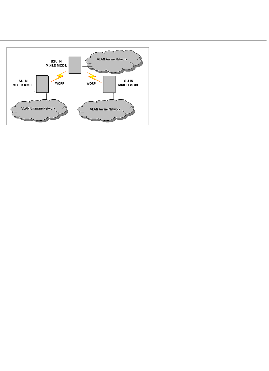
System Overview of Subscriber Module MeshMAX 5054 Series User Guide
Quality of Service (QoS)
49
Quality of Service (QoS)
NOTE: Quality of Service is configured on the Base Station Unit. See the Tsunami MP.11-R Installation and Management
Guide for more information.
The Quality of Service (QoS) feature is based on the 802.16 standard and defines the classes, service flows, and packet
identification rules for specific types of traffic. QoS main priority is to guarantee a reliable and adequate transmission
quality for all types of traffic under conditions of high congestion and bandwidth over-subscription.
There are already several pre-defined QoS classes, SFCs and PIRs available that you may choose from which cover the
most common types of traffic. If you want to configure something else, you start building the hierarchy of a QoS class by
defining PIRs; then you associate some of those PIRs to specific Service Flow classes (SFCs); you assign priorities to
each PIR within each SFC; and finally you define the QoS class by associating relevant SFCs to each QoS class.
Concepts and Definitions
The software supports QoS provisioning from the BSU only. You may define different classes of service on a BSU that
can then be assigned to the SUs that are associated, or that may get associated, with that BSU.
The software provides the ability to create, edit, and delete classes of service that are specified by the following hierarchy
of parameters:
• Packet Identification Rule (PIR) – up to 64 rules, including 17 predefined rules
• Service Flow class (SFC) – up to 32 SFs, including 7 predefined SFCs; up to 8 PIRs may be associated per SFC
• Priority for each rule within each SF class – 0 to 255, with 0 being lowest priority
• QoS class – up to 8 QoS classes, including 4 predefined classes; up to 4 SFCs may be associated per QoS class
Packet Identification Rule (PIR)
A Packet Identification Rule is a combination of parameters that specifies what type of traffic is allowed or disallowed.
The software allows to create up to 64 different PIRs, including 17 predefined PIRs. It provides the ability to create, edit,
and delete PIRs that contain none, one, or more of the following classification fields:
• Rule Name
• IP ToS (Layer 3 QoS identification)
• IP Protocol List containing up to 4 IP protocols
• 802.1p tag (layer 2 QoS identification)
• Up to 4 pairs of Source IP address + Mask
• Up to 4 pairs of Destination IP address + Mask
• Up to 4 source TCP/UDP port ranges

System Overview of Subscriber Module MeshMAX 5054 Series User Guide
Quality of Service (QoS)
50
• Up to 4 destination TCP/UDP port ranges
• Up to 4 source MAC addresses
• Up to 4 destination MAC addresses
•VLAN ID
• Ether type (Ethernet protocol identification)
A good example is provided by the 17 predefined PIRs. Note that these rules help to identify specific traffic types:
1. All – No classification fields, all traffic matches
2. Cisco VoIP UL
a. Protocol Source Port Range (16,000-32,000)
b. IP Protocol List (17 = UDP)
3. Vonage VoIP UL
a. Protocol Source Port Range (8000-8001, 10000-20000)
b. IP Protocol List (17 = UDP)
4. Cisco VoIP DL
a. Protocol Destination Port Range (16,000-32,000)
b. IP Protocol List (17 = UDP)
5. Vonage VoIP DL
a. Protocol Destination Port Range (8000-8001, 10000-20000)
b. IP Protocol List (17 = UDP)
6. TCP
a. IP Protocol List (6)
7. UDP
a. IP Protocol List (17)
8. PPPoE Control
a. Ethertype (type 1, 0x8863)
9. PPPoE Data
a. Ethertype (type 1, 0x8864)
10.IP
a. Ethertype (type 1, 0x800)
11. ARP
a. Ethertype (type 1, 0x806)
12.Expedited Forwarding
a. IP TOS/DSCP (low=0x2D, high=0x2D, mask = 0x3F)
13.Streaming Video (IP/TV)
a. IP TOS/DSCP (low=0x0D, high=0x0D, mask = 0x3F)
14.802.1p BE
a. Ethernet Priority (low=0, high=0) (this is the equivalent of the User Priority value in the TCI (Tag Control
Information) field of a VLAN tag)
15.802.1p Voice
a. Ethernet Priority (low=6, high=6) (this is the equivalent of the User Priority value in the TCI (Tag Control
Information) field of a VLAN tag)
16.802.1p Video

System Overview of Subscriber Module MeshMAX 5054 Series User Guide
Quality of Service (QoS)
51
a. Ethernet Priority (low=5, high=5) (this is the equivalent of the User Priority value in the TCI (Tag Control
Information) field of a VLAN tag)
17.L2 Broadcast/Multicast
a. Ethernet Destination (dest = 0x80000000, mask = 0x80000000)
Note that two different VoIP rule names have been defined for each direction of traffic, Uplink (UL) and Downlink (DL),
(index numbers 2 to 5). This has been done to distinguish the proprietary nature of the Cisco VoIP implementation as
opposed to the more standard Session Initiation Protocol (SIP) signaling found, for example, in the Vonage-type VoIP
service.
Service Flow Class (SFC)
A Service Flow class defines a set of parameters that determines how a stream of application data that matches a certain
classification profile will be handled. The software allows to create up to 32 different SFs, including seven predefined
SFs. The software provides the ability to create, edit, and delete SFs that contain the following parameters and values:
• Service flow name
• Scheduling type – Best Effort (BE); Real-Time Polling Service (RtPS)
• Service Flow Direction – Downlink (DL: traffic from BSU to SU); Uplink (UL: traffic from SU to BSU)
• Maximum sustained data rate (or Maximum Information Rate, MIR) – specified in units of 1 Kbps from 8 Kbps up to he
maximum rate of 108000 Kbps per SU
• Minimum reserved traffic rate (or Committed Information Rate, CIR) – specified in units of 1 Kbps from 0 Kbps up to
the maximum rate of 10000 Kbps per SU
• Maximum Latency – specified in increments of 5 ms steps from a minimum of 5 ms up to a maximum of 100 ms
• Tolerable Jitter – specified in increments of 5 ms steps from a minimum of 0 ms up to the Maximum Latency (in ms)
• Traffic priority – zero (0) to seven (7), 0 being the lowest, 7 being the highest
• Maximum number of data messages in a burst – one (1) to four (4), which affects the percentage of the maximum
throughput of the system
• Activation state – Active; Inactive
Note that traffic priority refers to the prioritization of this specific Service Flow.
The software tries to deliver the packets within the specified latency and jitter requirements, relative to the moment of
receiving the packets in the unit. For delay-sensitive traffic the jitter must be equal to or less than the latency. A packet is
buffered until an interval of time equal to the difference between Latency and Jitter (Latency – Jitter) has elapsed. The
software will attempt to deliver the packet within a time window starting at (Latency – Jitter) until the maximum Latency
time is reached. If the SFC’s scheduling type is real-time polling (rtPS), and the packet is not delivered by that time, it will
be discarded. This can lead to loss of packets without reaching the maximum throughput of the wireless link. For
example, when the packets arrive in bursts on the Ethernet interface and the wireless interface is momentarily maxed
out, then the packets at the “end” of the burst may be timed out before they can be sent.
Users are able to set up their own traffic characteristics (MIR, CIR, latency, jitter, etc.) per service flow class to meet their
unique requirements. A good example is provided by the seven predefined SFCs:
1. UL-Unlimited BE
a. Scheduling Type = Best Effort
b. Service Flow Direction = Uplink
c. Initialization State = Active
d. Maximum Sustained Data Rate = 20 Mbps
e. Traffic Priority = 0
2. DL-Unlimited BE (same as UL-Unlimited BE, except Service Flow Direction = Downlink)
3. UL-G711 20 ms VoIP rtPS
a. Schedule type = Real time Polling

System Overview of Subscriber Module MeshMAX 5054 Series User Guide
Quality of Service (QoS)
52
b. Service Flow Direction = Uplink
c. Initialization State = Active
d. Maximum Sustained Data Rate = 88 Kbps
e. Minimum Reserved Traffic Rate = 88 Kbps
f. Maximum Latency = 20 milliseconds
g. Traffic Priority = 1
4. DL-G711 20 ms VoIP rtPS (same as UL-G711 20ms VoIP rtPS, except Service Flow Direction = Downlink)
5. UL-G729 20 ms VoIP rtPS (same as UL-G711 20ms VoIP rtPS, except Maximum Sustained Data Rate and Maximum
Reserved Traffic Rate = 64 Kbps)
6. DL-G729 20 ms VoIP rtPS (same as UL-G729 20ms VoIP rtPS, except Service Flow Direction = Downlink)
7. DL-2Mbps Video
a. Schedule type = Real time Polling
b. Service Flow Direction = Downlink
c. Initialization State = Active
d. Maximum Sustained Data Rate = 2 Mbps
e. Minimum Reserved Traffic Rate = 2 Mbps
f. Maximum Latency = 20 milliseconds
g. Traffic Priority = 1
Note that two different VoIP Service Flow classes for each direction of traffic have been defined (index numbers 3 to 6)
which follow the ITU-T standard nomenclatures: G.711 refers to a type of audio companding and encoding that produces
a 64 Kbps bitstream, suitable for all types of audio signals. G.729 is appropriate for voice and VoIP applications, but
cannot transport music or fax tones reliably. This type of companding and encoding produces a bitstream between 6.4
and 11.8 Kbps (typically 8 Kbps) according to the quality of voice transport that is desired.
QoS Class
A QoS class is defined by a set of parameters that includes the PIRs and SFCs that were previously configured. The
software allows creating up to eight different QoS classes, including four predefined QoS classes. Up to four SF classes
can be associated to each QoS class, and up to eight PIRs can be associated to each SF class. For example, a QoS
class called “G711 VoIP” may include the following SFCs: “UL-G711 20 ms VoIP rtPS” and “DL-G711 20 ms VoIP rtPS”.
In turn, the SFC named “UL-G711 20 ms VoIP rtPS” may include the following rules: “Cisco VoIP UL” and “Vonage VoIP
UL”.
The software provides the ability to create, edit, and delete QoS classes that contain the following parameters:
• QoS class name
• Service Flow (SF) class name list per QoS class (up to four SF classes can be associated to each QoS class)
• Packet Identification Rule (PIR) list per SF class (up to eight PIRs can be associated to each SF class)
• Priority per rule which defines the order of execution of PIRs during packet identification process. The PIR priority is a
number in the range 0-63, with priority 63 being executed first, and priority 0 being executed last. The PIR priority is
defined within a QoS class, and can be different for the same PIR in some other QoS class. If all PIRs within one QoS
class have the same priority, the order of execution of PIR rules will be defined by the order of definition of SFCs, and
by the order of definition of PIRs in each SFC, within that QoS class.
A good example of this hierarchy is provided by the four predefined QoS classes:
1. Unlimited Best Effort
a. SF class: UL-Unlimited BE
PIR: All; PIR Priority: 0
b. SF class: DL-Unlimited BE
PIR: All; PIR Priority: 0

System Overview of Subscriber Module MeshMAX 5054 Series User Guide
Quality of Service (QoS)
53
2. G711 VoIP
a. SF class: UL-G711 20 ms VoIP rtPS
PIR: Vonage VoIP UL; PIR Priority: 1
PIR: Cisco VoIP UL; PIR Priority: 1
b. SF class: DL-G711 20 ms VoIP rtPS
PIR: Vonage VoIP DL; PIR Priority: 1
PIR: Cisco VoIP DL; PIR Priority: 1
3. G729 VoIP
a. SF class: UL-G729 20 ms VoIP rtPS
PIR: Vonage VoIP UL; PIR Priority: 1
PIR: Cisco VoIP UL; PIR Priority: 1
b. SF class: DL-G729 20 ms VoIP rtPS
PIR: Vonage VoIP DL; PIR Priority: 1
PIR: Cisco VoIP DL; PIR Priority: 1
4. 2Mbps Video
a. SF class: DL-2Mbps Video
PIR: Streaming Video (IP/TV); PIR Priority: 1
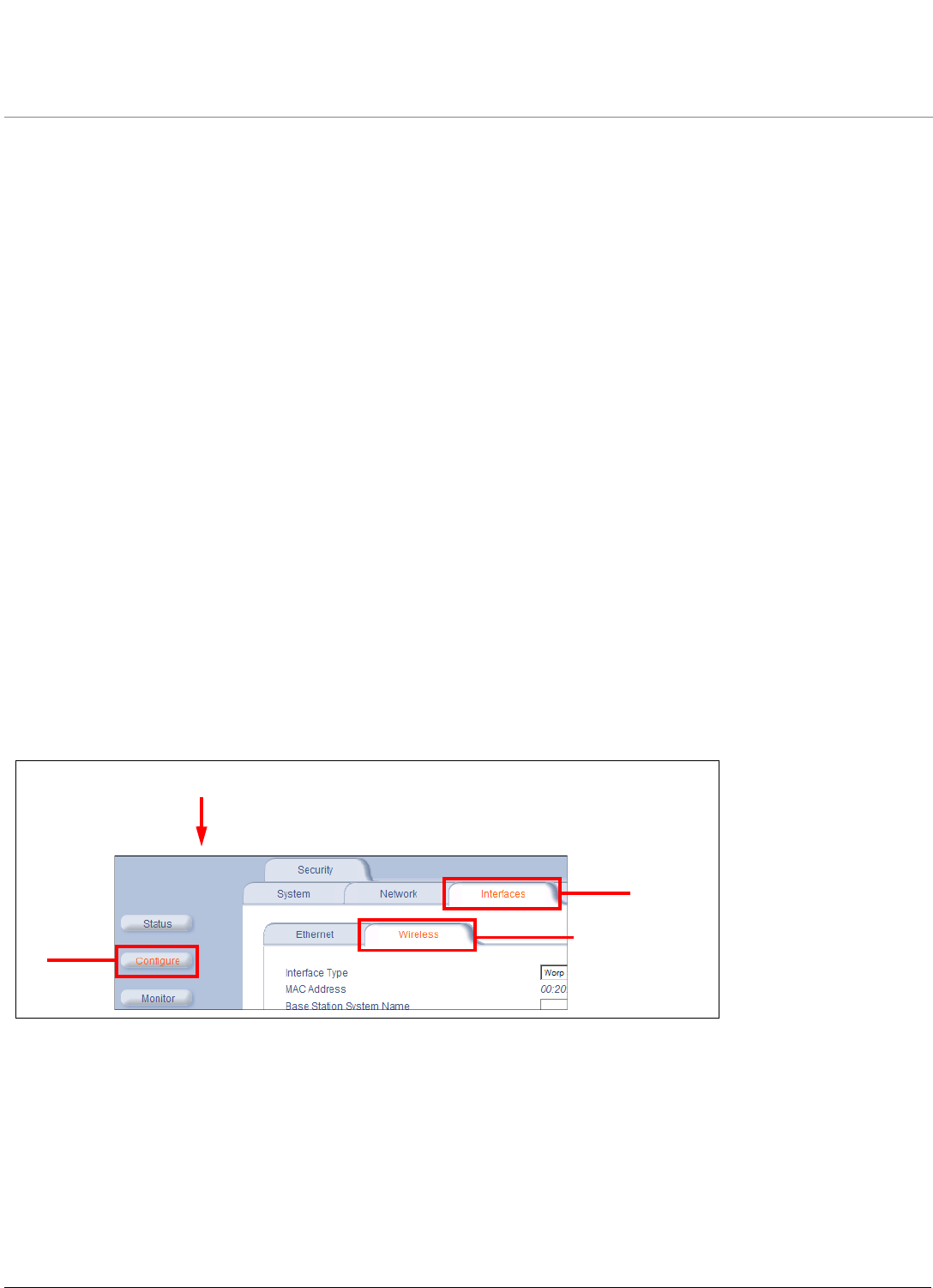
54
MeshMAX 5054 Series User Guide
4
Basic Management of Subscriber Module
This chapter describes basic features and functionality of the unit. In most cases, configuring these basic features is
sufficient. The following topics are discussed in this chapter:
•Navigation
•Rebooting and Resetting
•General Configuration Settings
•Monitoring Settings
•Security Settings
•Default Settings
•Upgrading the Unit
Navigation
To use the Web Interface for configuration and management, you must access the unit. With ScanTool you can
determine the unit’s current IP address. Then enter http://<ip address> in your Web browser (for example
http://10.0.0.1).
NOTE: If you have your Security Internet Options set to High, you may not be able to access the Web interface
successfully; a high security setting disables JavaScript, which is required for running Proxim’s Web browser
interface. Adding the radio’s IP address as a Trusted site should fix this problem.
The Web Interface consists of Web page buttons and tabs. A tab can also contain sub-tabs. The following figure shows
the convention used to guide you to the correct tab or sub-tab.
The Web Interface also provides online help, which is stored on your computer.
2
3
1
Click Configure > Interfaces > Wireless:

Basic Management of Subscriber Module MeshMAX 5054 Series User Guide
Rebooting and Resetting
55
Rebooting and Resetting
All configuration changes require a restart unless otherwise stated. New features explicitly state whether a reboot is
required or not. You can restart the unit with the Reboot command; see the first method described in the following
sub-sections.
Most changes you make become effective only when the Subscriber unit is rebooted. A reboot stores configuration
information in non-volatile memory and then restarts the Subscriber unit with the new values.
In some cases, the Subscriber unit reminds you that a reboot is required for a change to take effect. You need not reboot
immediately; you can reboot after you have made all your changes.
NOTE: Saving of the unit’s configuration occurs only during a controlled reboot or by specifically issuing the CLI Save
command. If you make changes to settings without a controlled reboot (command) and you have not issued the
Save command, a power outage would wipe out all changes since the last reboot. For example, entering static
routes takes effect immediately; however, the routes are not saved until the unit has gone through a controlled
reboot. Proxim strongly recommends saving your settings immediately when you finish making changes.
Rebooting
When you reboot, the changes you have made become effective and the Subscriber unit is restarted. The changes are
saved automatically in non-volatile memory before the actual reboot takes place.
To reboot, click Commands > Reboot > Reboot button. The Subscriber unit restarts the embedded software. During
reboot, you are redirected to a page showing a countdown timer, and you are redirected to the Status page after the
timer counts down to 0 (zero). The CLI is disconnected during reboot. This means that a new telnet session must be
started.
Resetting Hardware
If the unit does not respond for some reason and you are not able to reboot, you can restart by means of a hardware
reset. This restarts the hardware and embedded software. The last saved configuration is used. Any changes that you
have made since then are lost. To reset the hardware, press and release the RESET button on the Subscriber unit unit
with, for example, a pencil.
Soft Reset to Factory Default
If necessary, you can reset the unit to the factory default settings. This must be done only when you are experiencing
problems. Resetting to the default settings requires you to reconfigure the unit. To reset to factory default settings:
1. Click Commands > Reset.
2. Click the Reset to Factory Default button. The device configuration parameter values are reset to their factory
default values.
If you do not have access to the unit, you can use the procedure described in Hard Reset to Factory Default as an
alternative.
Reset and Reboot Functionality
The Reset and Reboot functionality on the power injector provides a way to reset the subscriber module and is applicable
during the boot up phase. To initiate the Reset and Reload functionality, use the Reload button, available on the side of
power injector.
The Reload feature implemented in the boot loader ensures that the application software image is removed from the
flash, and reloads the either the Mesh or Subscriber modules of MeshMAX unit, but they cannot be reloaded
simultaneously. As soon as the image is removed, the boot loader prompt appears to ensure that new application is
downloaded.User can use TFTP for normal operation. Press the “Reload” button to perform the reload functionality.

Basic Management of Subscriber Module MeshMAX 5054 Series User Guide
General Configuration Settings
56
• If the Reload button us pressed for 10-20 seconds and released, then reloading operation is not performed and the
operation is aborted.
• If the Reload button is pressed for 20 seconds and above, then the Subscriber module is reload state.
NOTE: Boot loader will display all events to the serial console, which will guide user to perform Relad functionality.
General Configuration Settings
•System Status: The status tab showing the system status is displayed automatically when you log into the Web
interface. It is also the default window displayed when you click the Status button on the left side of the window.
•System Configuration: The System Configuration window lets you change the unit’s country,system name,location
name, and so on (see the window to the right). The Country selection is required to enable the correct radio
parameters. The other details help distinguish this unit from other routers, and let you know whom to contact in case
of problems.
•IP Configuration: The IP Configuration window lets you change the unit’s IP parameters. These settings differ
between Routing and Bridge mode.
•Interface Configuration: The Interface configuration pages let you change the Ethernet and Wireless parameters.
The Wireless tab is displayed by default when you click the Interfaces tab.
•Ethernet: To configure the Ethernet interface, click Configure > Interfaces > Ethernet. You can set the
Configuration parameter from this tab for the type of Ethernet transmission. The recommended setting is
auto-speed auto-duplex.
•Wireless: To configure the wireless interface, click Configure > Interfaces > Wireless. For the Subscriber module,
the wireless interface is always in WORP Satellite mode (selected from the Interface Type drop-down box).
•VLAN Configuration: VLANs are configured on the Base Station Unit only.

Basic Management of Subscriber Module MeshMAX 5054 Series User Guide
Monitoring Settings
57
Monitoring Settings
The unit offers various facilities to monitor its operation and interfaces. Only the most significant monitoring categories
are mentioned here.
•Wireless: To monitor the wireless interfaces, click Monitor > Wireless. This tab lets you monitor the general
performance of the radio and the performance of the WORP Base or WORP Satellite interfaces.
•Interfaces: To monitor transmission details, click Monitor > Interfaces. The Interfaces tab provides detailed
information about the MAC-layer performance of the wireless network and Ethernet interfaces.
•Per Station: Click Monitor > Per Station to view Station Statistics. On the SU, the Per Station page shows
statistics of the BSU to which the SU is registered. The page’s statistics refresh every 4 seconds.
Security Settings
To prevent misuse, the Subscriber unit provides wireless data encryption and password-protected access. Be sure to set
the encryption parameters and change the default passwords.
In addition to Wired Equivalent Privacy (WEP), the units support Advanced Encryption Standard (AES) 128-bit
encryption. Two types of the AES encryption are available. The AES CCM protocol is now also supported.
Proxim highly recommends you change the Network Name,Encryption Key, and Shared Secret as soon as possible.
To do so, click Configure > Interfaces >Wireless. The encryption key is set using the Security tab. For systems that
will use roaming features, the Network Name,Encryption Key, and the Shared Secret should each be the same for all
SUs that are allowed to roam as well as for all BSUs to which these SUs are allowed to roam.
Encryption
You can protect the wireless data link by using encryption. Encryption keys can be 5 (64-bit), 13 (WEP 128-bit), or 16
(AES 128-bit) characters in length. Both ends of the wireless data link must use the same parameter values. In addition to
Wired Equivalent Privacy (WEP), the unit supports Advanced Encryption Standard (AES) 128-bit encryption.
To set the encryption parameters, click Configure > Security > Encryption. See Encryption.
Passwords
Access to the units are protected with passwords. The default password is public. For better security it is recommended
to change the default passwords to a value (6-32 characters) known only to you.
To change the unit’s HTTP, Telnet, or SNMP passwords, click Configure > Management > Password. See Passwords.

Basic Management of Subscriber Module MeshMAX 5054 Series User Guide
Default Settings
58
Default Settings
Feature Default Setting
System Name Subscriber Module
Mode of Operation Bridge
Routing Disabled
IP Address Assignment Type Static
IP Address 10.0.0.1
Subnet Mask 255.255.255.0
Default Router IP Address 10.0.0.1
Default TTL 64
RIPv2 Enabled when in Routing Mode
Base Station System Name <blank>
Network Name OR_WORP
Frequency Channel Channel 149, Frequency 5.745 GHz (FCC Only devices)
DFS Enabled (World Mode devices)
Transmit Power Control (TPC) 0 dB
Data Rate 36 Mbps
Turbo Mode Disabled
Channel Bandwidth 20 MHz
Registration Timeout 5
Network Secret public
Serial port Baud Rate (for factory use only) 9600
SNMP Management Interface Enabled
Telnet Management Interface Enabled
HTTP Management Interface Enabled
HTTP Port 80
Telnet Port 23
Telnet Login Timeout 30
Telnet Session Timeout 900
Password public
Maximum Satellites (per BSU) 250
MAC Authentication Disabled
Radius Authentication Disabled
Encryption Disabled
Static MAC Address Filter Disabled / No Entries
Ethernet Protocol Filtering All Filters Disabled
DFS Priority Frequency Channel Disabled
Announcement Period (when roaming enabled) 100 ms
Multi-Frame Bursting Enabled
Storm Threshold Broadcast/Multicast Unlimited
Broadcast Protocol Filtering All Protocols Allowed
Dynamic Data Rate Selection Disabled
Roaming Disabled
NAT Disabled
Intra-Cell Blocking Disabled
Antenna Alignment Disabled

Basic Management of Subscriber Module MeshMAX 5054 Series User Guide
Upgrading the Unit
59
Upgrading the Unit
The units are equipped with embedded software that can be updated when new versions are released. Updating the
embedded software is described Web Interface Image File Download. A TFTP server is provided on the Documentation
and Software CD; the server is required to transfer the downloaded file to the unit. See TFTP Server Setup.
To access all resolved problems in our solution database, or to search by product, category, keywords, or phrases, go to
http://secure.proxim.com You can also find links to drivers, documentation, and downloads at this link.
Country Selection US-only device – US
World device – GB
DHCP Server Disabled
DHCP Relay Disabled
Spanning Tree Protocol Disabled
Antenna Gain 0 (For DFS Threshold compensation)
Satellite Density Large
VLAN Mode BSU: Transparent Mode
SU: Transparent mode when BSU is in Transparent mode;
Trunk mode when the BSU is in Trunk mode.
Access VLAN ID BSU: N/A; SU: 1
Access VLAN Priority BSU: N/A; SU: 0
Management VLAN ID BSU: -1; SU: -1
Management VLAN Priority BSU: 0; SU: 0
Trunk VLAN ID BSU: N/A; SU: -1
Feature Default Setting

60
MeshMAX 5054 Series User Guide
5
System Status
This section describes viewing system status and event log information from the unit’s Web Interface.
•Subscriber Module
–Status
–Event Log
•Mesh and Access Point Module
Subscriber Module
Click on the Status button to access system and event log information. See the following sections:
•Status
•Event Log
Help and Exit buttons also appear on each page of the Web interface; click the Help button to access online help; click
the Exit button to exit the application.
For an introduction to the basics of management, see Basic Management of Subscriber Module.
Status
The Status tab showing the system status is displayed automatically when you log into the Web Interface. It also is the
default window displayed when you click the Status button on the left side of the window.
The Status tab shows the System Status and the System Traps.
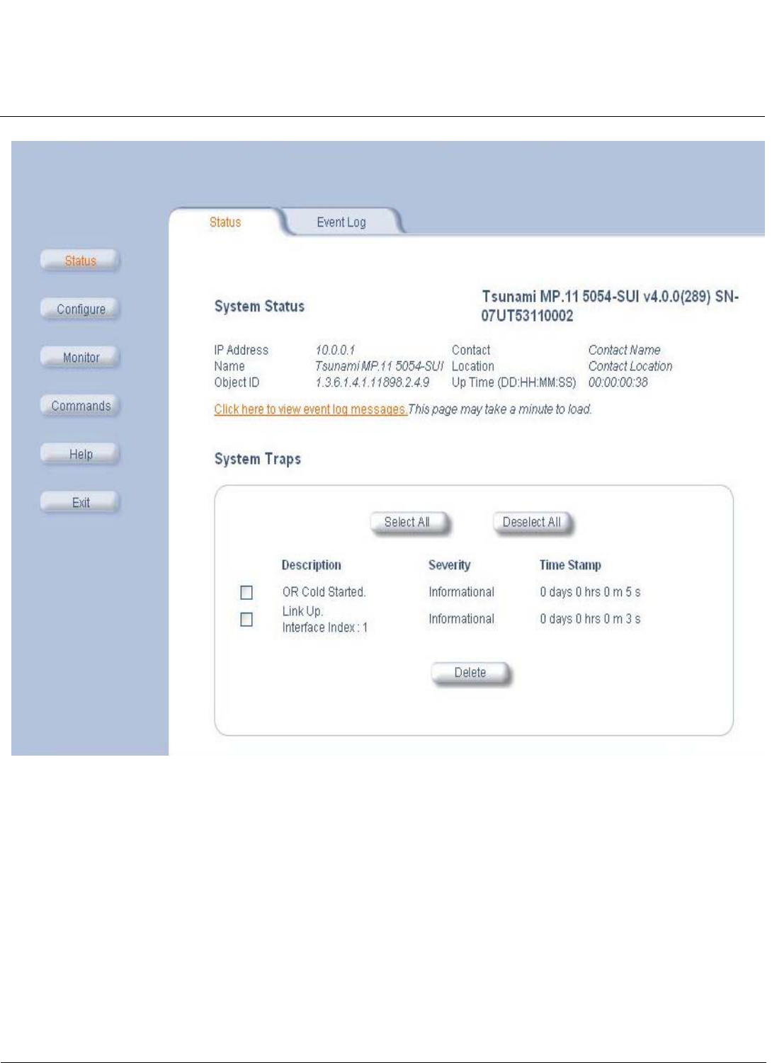
System Status MeshMAX 5054 Series User Guide
Subscriber Module
61
Figure 5-1 System Status Screen of Subscriber Module
System Status
The basic system status is shown in this section, including the version number of the embedded software.
Systems Traps
The status of system traps is shown in this section. System traps occur when the Subscriber unit encounters
irregularities. Deleting system traps has no effect on the operation of the Subscriber unit. System traps also are sent to an
SNMP manager station (if so configured).
Event Log
Click the Status button and the Event Log tab to view the contents of your Event Log. The Event Log keeps track of
events that occur during the operation of the Subscriber unit. The Event Log displays messages that may not be
captured by System Traps, such as the Transmit Power for the Frequency Channel selected.
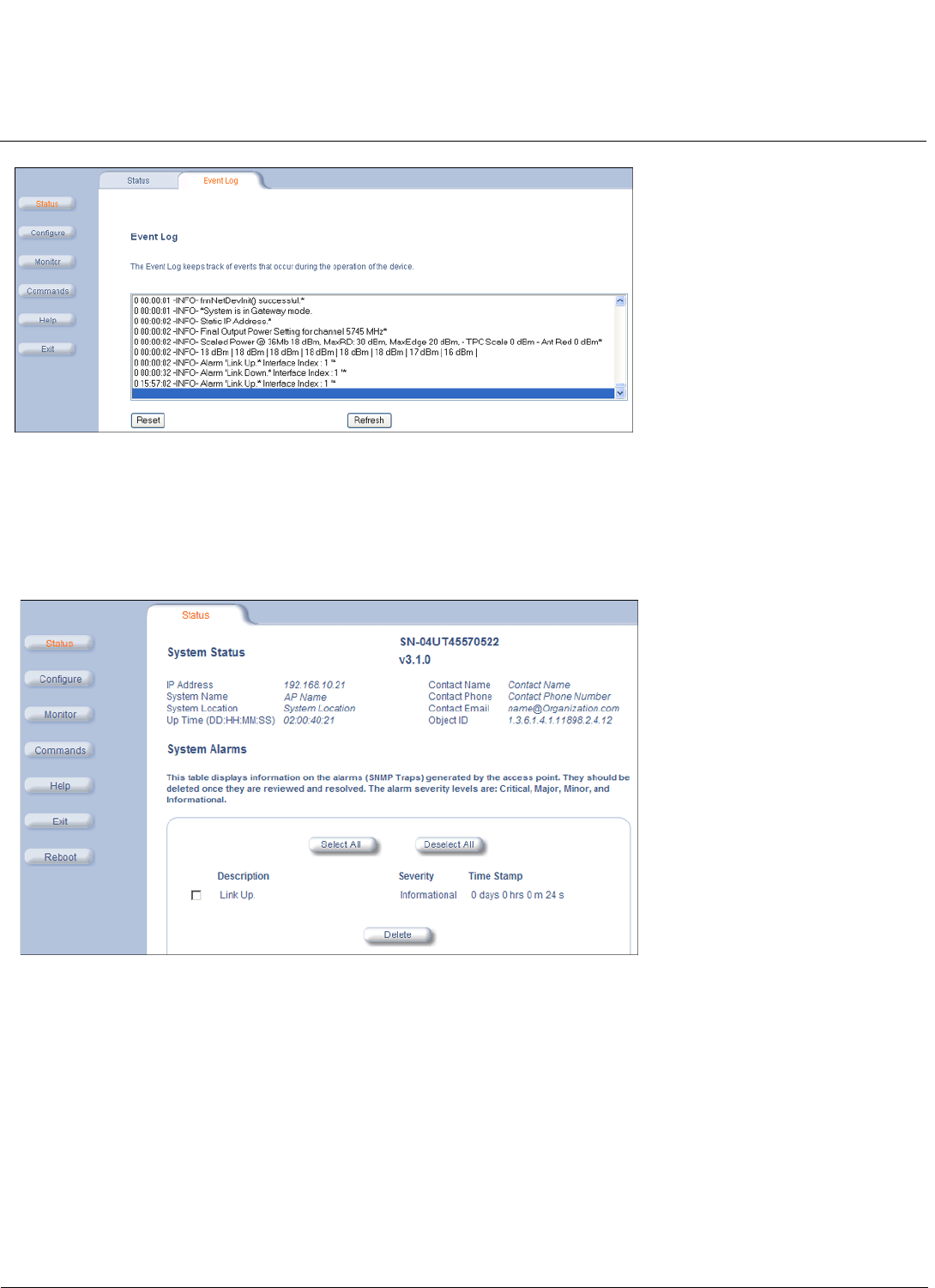
System Status MeshMAX 5054 Series User Guide
Mesh and Access Point Module
62
Figure 5-2 Event Log Screen of Subscriber Module
Mesh and Access Point Module
The first screen displayed after Logging In is the System Status screen. You can always return to this screen by clicking
the Status button.
Figure 5-3 System Status Screen of Mesh and Access Point Module
The System Status screen provides the following information:
•System Status: This area provides system-level information, including the unit’s IP address and contact information.
•System Alarms: System traps (if any) appear in this area. Each trap identifies a specific severity level: critical, major,
minor, and informational.
NOTE: On APs with model numbers ending in -WD, an operating Country must be selected (during the Setup Wizard
or on the Configure > System tab). If a country has not been selected, an informational message will appear
in the System Alarms list, and you will be unable to configure interface parameters.
From this screen, you can also access the AP’s monitoring and configuration options by clicking on the buttons on the left
of the screen.

63
MeshMAX 5054 Series User Guide
6
Configuration
This section describes configuring the MeshMAX 5054 settings using the unit’s web interface. The following topics are
discussed in this chapter:
Configuring the Subscriber Module
•System Parameters
–Bridge and Routing Modes
•Network Parameters
–IP Configuration
–Roaming
–DHCP Server
–Spanning Tree (Bridge Mode Only)
–IP Routes (Routing Mode only)
–DHCP Relay Agent (Routing Mode Only)
•Interface Parameters
–Wireless
–Ethernet
•SNMP Parameters
–Trap Host Table
•Management Parameters
–Passwords
–Services
•Security Parameters
–MAC Authentication (BSU Only)
–Encryption
•Filtering Parameters
–Overview
–Ethernet Protocol
–Static MAC Address Filtering
–Storm Threshold
–Broadcast Protocol Filtering
–IP Access Table Filtering
•RIP Parameters (Routing Mode Only)
–RIP Example
–RIP Notes
•NAT (Routing Mode Only)
–NAT Static Port Mapping Table
–Supported Session Protocols
Advanced Configuration of Mesh and Access Point Module
•System Parameters

Configuration MeshMAX 5054 Series User Guide
64
–Dynamic DNS Support
•Network Parameters
–IP Configuration
–DHCP Server
–DHCP Relay Agent
–Link Integrity
–SNTP (Simple Network Time Protocol)
•Interface Parameters
–Operational Mode
–Wireless-A (802.11a or 4.9 GHz Radio) and Wireless-B (802.11b/g Radio)
–Ethernet
–Mesh
•Management
–Passwords
–IP Access Table
–Services
–Automatic Configuration (AutoConfig)
–Hardware Configuration Reset (CHRD)
•Filtering
–Ethernet Protocol
–Static MAC
–Advanced
–TCP/UDP Port
•Alarms
–Groups
–Syslog
–Rogue Scan
•Bridge
–Spanning Tree
–Storm Threshold
–Intra BSS
–Packet Forwarding
•QoS
–Wi-Fi Multimedia (WMM)/Quality of Service (QoS) Introduction
–Policy
–Priority Mapping
–Enhanced Distributed Channel Access (EDCA)
•Radius Profiles
–RADIUS Servers per Authentication Mode and per VLAN
–Configuring Radius Profiles
–MAC Access Control Via RADIUS Authentication
–802.1x Authentication using RADIUS
–RADIUS Accounting
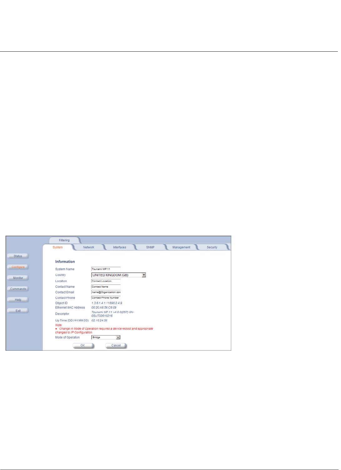
Configuration MeshMAX 5054 Series User Guide
Configuring the Subscriber Module
65
•SSID/VLAN/Security
–VLAN Overview
–Management VLAN
–Security Profile
–MAC Access
–Wireless-A or Wireless-B
Configuring the Subscriber Module
Click the Configure button to access configuration settings.
Help and Exit buttons also appear on each page of the Web interface; click the Help button to access online help; click
the Exit button to exit the application.
For an introduction to the basics of management, see Basic Management of Subscriber Module.
System Parameters
The System configuration page lets you change the unit’s System Name,Location,Mode of Operation, and so on.
These details help you to distinguish the unit from other routers and let you know whom to contact in case you experience
problems.
Click Configure > System; the following window is displayed.
You can enter the following details:
•System Name: This is the system name for easy identification of the SU. The System Name field is limited to a length
of 32 bytes. Use the system name of a BSU to configure the Base Station System Name parameter on an SU if you
want the SU to register only with this BSU. If the Base Station System Name is left blank on the SU, it can register
with any Base Station that has a matching Network Name and Network Secret.
•Country: Upon choosing a country/band, the Dynamic Frequency Selection (DFS) and Transmit Power Control (TPC)
features are enabled automatically if the selected country/band has a regulatory domain that requires it. The Country
selection pre-selects and displays only the allowed frequencies for the selected country/band.
Click Configure >Interfaces > Wireless to see the channel/frequency list for the selected Country.
NOTE: If All Channels 5 GHz is selected from the Country drop-down menu, any channel in the 5 GHz range are
displayed for manual selection.

Configuration MeshMAX 5054 Series User Guide
Configuring the Subscriber Module
66
NOTE: Units sold only in the United States are pre-configured to scan and display only the outdoor frequencies
permitted by the FCC. No other Country selections, channels, or frequencies can be configured. Units sold
outside of the United States support the selection of a Country by the professional installer. If you change the
Country, a reboot of the unit is necessary for the upgrade to take place.
For a non US-only device, the default country selected is United Kingdom (GB).
Note the following:
– The channel center frequencies are not regulated; only the band edge frequencies are regulated.
– If, before upgrade, US was selected as a country for a non US-Only device (which is an incorrect configuration),
the country is changed automatically to United Kingdom upon upgrade.
See Country Codes for Subscriber Module for a list of country codes.
•Location: This field can be used to describe the location of the unit, for example “Main Lobby.”
•Contact Name,Contact Email, and Contact Phone: In these fields, you can enter the details of the person to
contact.
•ObjectID: This read-only field shows the OID of the product name in the MIB.
•Ethernet MAC Address: This read-only field shows the MAC address of the Ethernet interface of the device.
•Descriptor: This read-only field shows the product name and firmware build version.
•Up Time: This read-only field shows the length of time the device has been up and running since the last reboot.
•Mode of Operation: This drop-down menu is used to set the unit as a bridge (layer 2) or as a router (layer 3). See
Bridge and Routing Modes for more information.
Bridge and Routing Modes
Bridge Mode
A bridge is a product that connects a local area network (LAN) to another LAN that uses the same protocol (for example,
Ethernet). You can envision a bridge as being a device that decides whether a message from you to someone else is
going to the local area network in your building or to someone on the local area network in the building across the street.
A bridge examines each message on a LAN, passing those known to be within the same LAN, and forwarding those
known to be on the other interconnected LAN (or LANs).
In bridging networks, computer or node addresses have no specific relationship to location. For this reason, messages
are sent out to every address on the network and are accepted only by the intended destination node. Bridges learn
which addresses are on which network and develop a learning table so that subsequent messages can be forwarded to
the correct network.
Bridging networks are generally always interconnected LANs since broadcasting every message to all possible
destination would flood a larger network with unnecessary traffic. For this reason, router networks such as the Internet
use a scheme that assigns addresses to nodes so that a message or packet can be forwarded only in one general
direction rather than forwarded in all directions.
A bridge works at the data-link (physical) layer of a network, copying a data packet from one network to the next network
along the communications path.
The default Bridging Mode is Transparent Bridging.
This mode works if you do not use source routing in your network. If your network is configured to use source routing,
then you should use either Multi-Ring SRTB or Single-Ring SRTB mode.
In Multi-Ring SRTB mode, each unit must be configured with the Bridge number, Radio Ring number, and Token Ring
number. The Radio Ring number is unique for each Token Ring Access Point and the Bridge number is unique for each
Token Ring Access Point on the same Token Ring segment.
Alternatively, you may use the Single-Ring SRTB mode. In this mode, only the Token Ring number is required for
configuration.

Configuration MeshMAX 5054 Series User Guide
Configuring the Subscriber Module
67
Routing Mode
Routing mode can be used by customers seeking to segment their outdoor wireless network using routers instead of
keeping a transparent or bridged network. By default the unit is configured as a bridge device, which means traffic
between different outdoor locations can be seen from any point on the network.
By switching to routing mode, your network now is segmented by a layer 3 (IP) device. By using Routing mode, each
network behind the BSU and SUs can be considered a separate network with access to each controlled through routing
tables.
The use of a router on your network also blocks the retransmission of broadcast and multicast packets on your networks,
which can help to improve the performance on your outdoor network in larger installations.
The use of Routing mode requires more attention to the configuration of the unit and thorough planning of the network
topology of your outdoor network. BSU and SUs can use routing mode in any combination. For example, you may have
the BSU in Routing mode and the SU in Bridge mode, or vice versa.
When using Routing mode, pay close attention to the configuration of the default gateway both on your unit and on your
PCs and servers. The default gateway controls where packets with unknown destinations (Internet) should be sent. Be
sure that each device is configured with the correct default gateway for the next hop router. Usually this is the next router
on the way to your connection to the Internet. You can configure routes to other networks on your Intranet through the
addition of static routes in your router’s routing table.
Key Reasons to Use Routing Mode
One key reason why customers would use Routing mode is to implement virtual private networks (VPNs) or to let nodes
behind two different SUs communicate with each other. Many customers do this same thing in Bridging mode by using
secondary interfaces on the router at the BSU or virtual interfaces at the BSU in VLAN mode to avoid some of the
drawbacks of IP Routing mode.
Routing mode prevents the transport of non-IP protocols, which may be desirable for Service Providers.
Routing mode is usually more efficient because Ethernet headers are not transported and non-IP traffic is blocked.
Benefits of using Routing Mode
• Enabling RIP makes the Subscriber unit easier to manage for a Service Provider that uses RIP to dynamically
manage routes. RIP is no longer very common for Service Providers or Enterprise customers and an implementation
of a more popular routing protocol like OSPF would be desirable.
• Routing mode saves bandwidth by not transporting non-IP protocols users might have enabled, like NetBEUI or
IPX/SPX, which eliminates the transmission of broadcasts and multicasts.
– The MAC header is:
• Destination MAC 6 bytes
• Source MAC 6 bytes
• Ethernet Type 2 bytes
If the average packet size is 1000 bytes, the overhead saved is 1.5%; With a frame size of 64 bytes, the overhead saved
is 20%; and for frame sizes of 128 bytes, the saving is 10%. Network researches claim that most network traffic consists
of frames smaller than 100 bytes.
In order to support routers behind the SUs with multiple subnets and prevent routing loops, you want individual routes
(and more then one) per SU.
Routing Mode Examples
In the first example, both the BSU and the SUs are configured for Routing mode. This example is appropriate for
businesses connecting remote offices that have different networks.
In example 2, the BSU is in Routing mode and the SUs are in Bridge mode. Notice the PCs behind the SUs must
configure their default gateways to point to the BSU, not the SU.
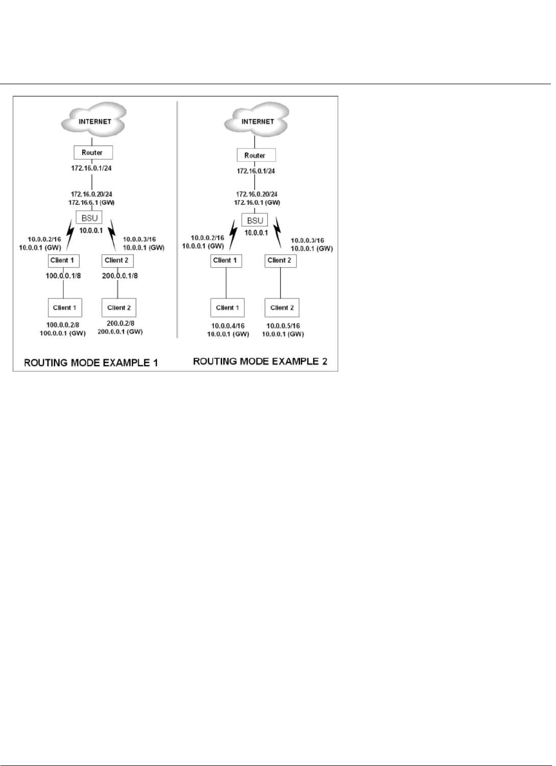
Configuration MeshMAX 5054 Series User Guide
Configuring the Subscriber Module
68
Notes:
• One of the most important details to pay attention to in Routing mode are the unit’s and the PC’s default gateways. It
is a common mistake to set up the PC’s gateway to point to the SU when the SU is in Bridge mode and the BSU is in
Routing mode. Always check to make sure the PCs on your network are configured to send their IP traffic to the
correct default gateway.
• Be sure to reboot the unit to permanently save static routes. New routes take effect immediately without a reboot, but
are not permanently saved with your configuration until you do reboot the device. An unexpected power outage could
cause static routes you entered to “disappear” when the unit reboots if they have not been saved. You also should
save a copy of your unit’s configuration file in case the unit must be reloaded. This saves you from being required to
re-enter numerous static routes in a large network.
• The routing table supports up to 500 static routes.
Network Parameters
The Network tab contains the following sub-tabs. Note that the availability of some sub-tabs depends on whether the unit
is in Bridge or Routing Mode:
IP Configuration
Click Configure > Network > IP Configuration to view and configure local IP address information. Configurable settings
differ between Bridge mode and Routing mode.
Bridge Mode
If the device is configured in Bridge mode, the following screen is displayed:
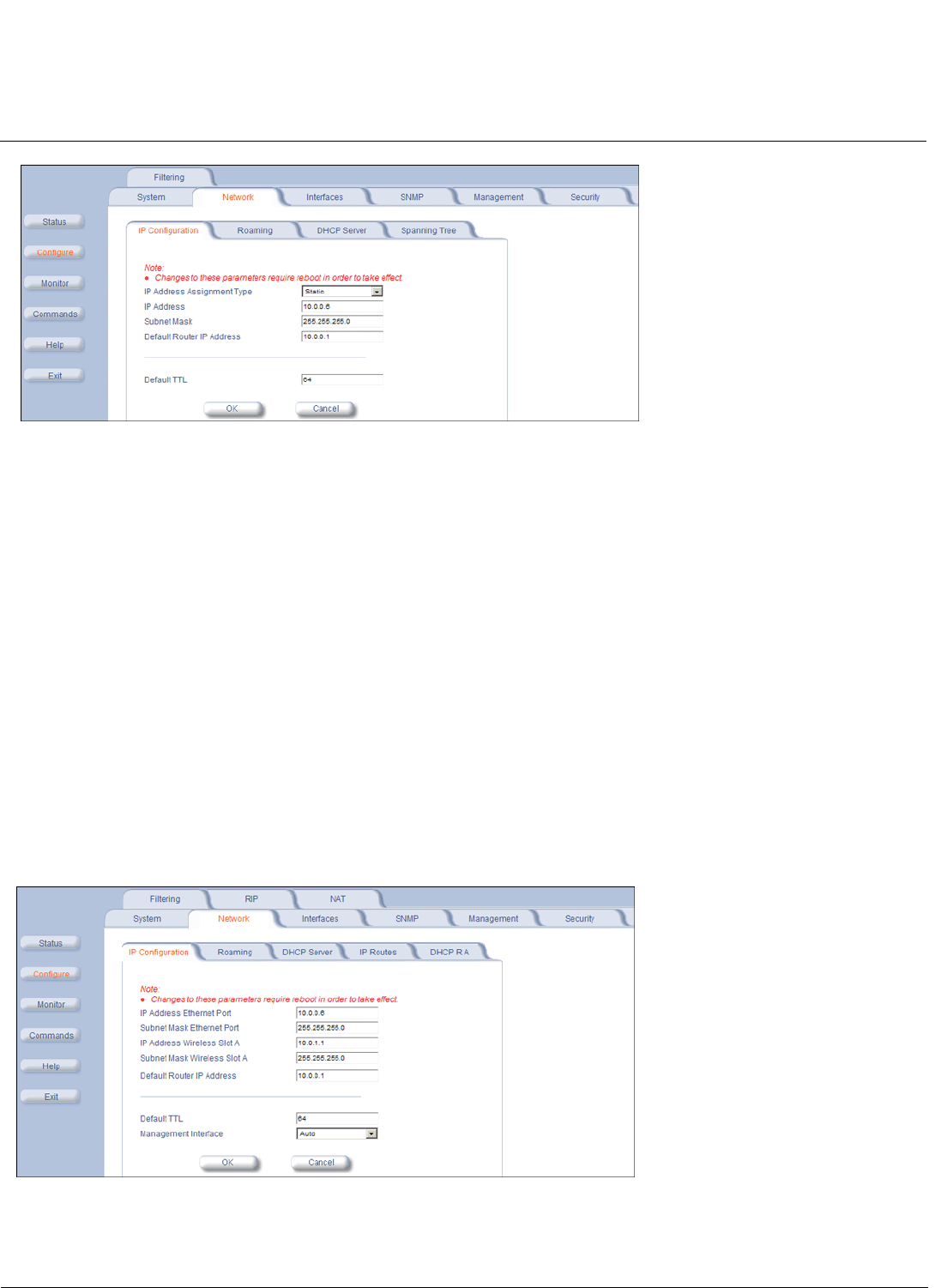
Configuration MeshMAX 5054 Series User Guide
Configuring the Subscriber Module
69
Configure or view the following parameters:
•IP Address Assignment Type:
–Select Static if you want to assign a static IP address to the unit. Use this setting if you do not have a DHCP
server or if you want to manually configure the IP settings
–Select Dynamic to have the device run in DHCP client mode, which gets an IP address automatically from a
DHCP server over the network.
When the unit is in Bridge mode, only one IP address is required. This IP address also can be changed with ScanTool.
IP Address: The unit’s static IP address (default IP address is 10.0.0.1). This parameter is configurable only if the IP
Address Assignment Type is set to Static.
•Subnet Mask: The mask of the subnet to which the unit is connected (the default subnet mask is 255.255.255.0).
This parameter is configurable only if the IP Address Assignment Type is set to Static.
•Default Router IP Address: The IP address of the default gateway. This parameter is configurable only if the IP
Address Assignment Type is set to Static.
•Default TTL: The default time-to-live value.
Routing Mode
If the device is configured in Routing mode, both Ethernet and Wireless interfaces require an IP address. The following
screen is displayed:
Configure or view the following parameters:
•IP Address Ethernet Port: The unit’s Ethernet IP address. The default is 10.0.1.1.
•Subnet Mask Ethernet Port: The unit’s Ethernet IP address subnet mask.The default is 255.255.255.0.

Configuration MeshMAX 5054 Series User Guide
Configuring the Subscriber Module
70
•IP Address Wireless Slot A: The unit’s wireless IP address. The default is 10.0.1.1.
•Subnet Mask Wireless Slot A: The unit’s wireless IP address subnet mask.
•Default Router IP Address: The router’s IP address.
•Default TTL: The default time-to-live value.
•Management Interface: The interface used to manage the device. Select Ethernet, Wireless, or Auto.
Roaming
Roaming Overview
Roaming is a feature by which an SU terminates the session with the current BSU and starts the registration procedure
with another BSU when it finds the quality of the other BSU to be better. Roaming provides MAC level connectivity to the
SU that roams from one BSU to another. Roaming takes place across the range of frequencies and channel bandwidths
(5, 10, or 20 MHz, as available) that are available per configuration. The current release offers handoff times of up to a
maximum of 80 ms. This is fast enough to allow the SU to seamlessly roam from one BSU to the other therefore
supporting session persistence for delay-sensitive applications. The feature also functions as BSU backup in case the
current BSU fails or becomes unavailable.
The Roaming feature lets the SU monitor local SNR and data rate for all frames received from the current BSU. As long
as the average local SNR for the current BSU is greater than the slow scanning threshold, and the number of
retransmitted frames is greater than the slow scanning threshold given in percentage, the SU does not scan other
channels for a better BSU.
•The normal scanning procedure starts when the average local SNR for the current BSU is less than or equal to the
slow scanning threshold and the number of retransmitted frames is greater than the slow scanning threshold given in
percentage. During the normal scanning procedure the SU scans the whole list of active channels while maintaining
the current session uninterrupted.
•Fast scanning is the scanning procedure performed when the average local SNR for the current BSU is very low
(below the fast scanning threshold) and the number of retransmitted frames is greater than the fast scanning
retransmission threshold given in%, so that the current session should terminate as soon as possible. During this
procedure, the SU scans other active channels as fast as possible.
Roaming can only occur if the normal scanning or fast scanning procedure is started under the following conditions:
1. If the roaming is started from the normal scanning procedure (after the SU scans all the active channels), the SU
selects the BSU with the best SNR value on all available channels. The SU roams to the best BSU only if the SNR
value for the current BSU is still below the slow scanning SNR threshold, and best BSU offers a better SNR value for
at least roaming threshold than the current BSU. The SU starts a new registration procedure with the best BSU
without ending the current session.
2. If the roaming is started from the fast scanning procedure, the SU selects the first BSU that offers better SNR than the
current BSU, and starts a new registration procedure with the better BSU without ending the current session.
Roaming with Dynamic Data Rate Selection (DDRS) Enabled
When an SU roams from BSU-1 to BSU-2 and DDRS is enabled, the data rate at which the SU connects to BSU-2 is the
default DDRS data rate. If this remains at the factory default of 6 Mbps, there can be issues with the application if it
requires more then 6 Mbps (for example multiple video streams).
Applications requiring a higher data rate could experience a slight data loss during the roaming process while DDRS
selects a higher rate (based upon link conditions).
When the applications re-transmit at a possibly slower rate, the WORP protocol initially services the data at 6 Mbps and
increases the data rate up to the "Maximum DDRS Data Rate" (ddrsmaxdatarate) one step at a time. Because the
applications are not being serviced at the best possible rate, they further slow down the rate of data send.
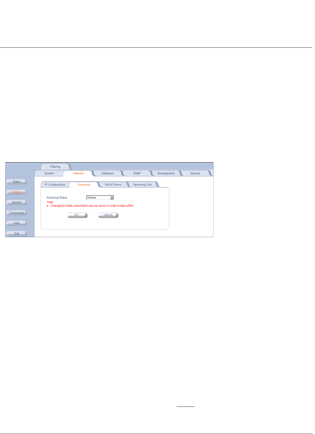
Configuration MeshMAX 5054 Series User Guide
Configuring the Subscriber Module
71
The DDRS algorithm requires data traffic (a minimum of 128 frames) to raise the rate to a higher value. Although roaming
occurs successfully, the previous scenario causes applications to drop their sessions; hence session persistence is not
maintained.
NOTE: You must know the data rate required for the applications running and you must ensure (during network
deployment) that the ranges and RF links can support the necessary data rate. You also must set the default
DDRS data rate at the capacity necessary for the application so that it connects to the next Base Station at the
required capacity if roaming occurs. Set the “Default DDRS Data Rate” (ddrsdefdatarate) to a greater value (24,
36, 48 or 54 Mbps, for example) for applications requiring session persistence when roaming occurs.
Roaming Configuration
Click Configure > Network > Roaming to configure Roaming.
Enable or disable the Roaming feature in the Roaming Status drop-down box. The default value is disabled.
NOTE: To enable roaming, you must enable Roaming Status on both the BSU and the SU.
An SU scans all available channels for a given bandwidth during roaming. In order to reduce the number of channels an
SU has to scan and thus decrease the roaming time, a channel priority list that tells the SU what channels to scan is
implemented. Each channel in the channel priority list is specified with its corresponding bandwidth and the priority with
which it should be scanned, either “Active” (standard priority), “Active High” (high priority), or “Inactive”.
An SU will scan all channels indicated as “Active” during roaming. However, it will scan active channels indicated as
“High Priority” before scanning active channels indicated as standard priority. Channels that are not going to be used in
the wireless network should be configured as “Inactive” so that the SU can skip over those channels during scanning
saving this way time.
A BSU broadcasts the channel priority list to all valid authenticated SUs in its sector. It re-broadcasts the channel priority
list to all SUs every time the list is updated on the BSU. For information for configuring the channel priority list on the BSU
see the Tsunami MP.11-R Installation and Management Guide.
Note that an SU may roam from one BSU with a bandwidth setting to another BSU with a different bandwidth setting.
Since in this case more channels need to be scanned than with only one channel bandwidth setting, it is important that
the channel priority list mentioned above is properly used to limit scanning time.
When Scanning Across Bandwidth on the SU is enabled, the SU supports bandwidth selection of the communications
channel of either 20 MHz, 10 MHz, or 5 MHz, as available. This allows the BSUs in the network to be set to different
bandwidths while an SU can still roam from one BSU to the next, because it will not only scan other frequencies (when
the signal level or quality are lower than the threshold) but it will also switch to other bandwidths to find a BSU that may
be on another bandwidth than its current one.
During roaming, the SU will start scanning first the channels on its current bandwidth from the “Active” channel list
provided by the BSU in order to find a BSU to register, since that is the most likely setting for other BSUs in the network.
If the SU cannot find an acceptable roaming candidate, it will switch bandwidth and start scanning channels on that
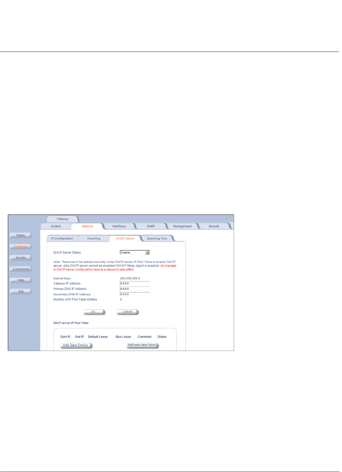
Configuration MeshMAX 5054 Series User Guide
Configuring the Subscriber Module
72
corresponding bandwidth from the “Active” channel list provided by the BSU. The process is repeated until the SU finds
an appropriate BSU to register.
In the example above, an SU whose current bandwidth is 20 MHz will start scanning all active channels within the
bandwidth of 20 MHz. If it cannot find a suitable BSU, it will switch to a 10 MHz bandwidth and start scanning all active
channels within that bandwidth, in this case channel 56 first since it is configured as high priority and channel 60 next. No
channels will be scanned on the 5 MHz bandwidth since all those channels are configured as inactive.
DHCP Server
When enabled, the DHCP server allows allocation of IP addresses to hosts on the Ethernet side of the SU or BSU.
Specifically, the DHCP Server feature lets the SU or BSU respond to DHCP requests from Ethernet hosts with the
following information:
• Host IP address
• Gateway IP address
• Subnet Mask
• DNS Primary Server IP address
• DNS Secondary Server IP
Click Configure > Network > DHCP Server to enable the unit on a DHCP Server.
The following parameters are configurable:
•DHCP Server Status: Verify that DHCP Relay Agent is disabled. After you have made at least one entry in the DHCP
server IP Pool Table, enable DHCP Server by selecting Enable from the DHCP Server Status pull-down menu.
NOTE: There must be at least one entry in the DHCP server IP Pool Table to enable DHCP server. Also, DHCP
server cannot be enabled if DHCP Relay Agent is enabled.
•Subnet Mask: The unit supplies this subnet mask in its DHCP response to a DHCP request from an Ethernet host.
Indicates the IP subnet mask assigned to hosts on the Ethernet side using DHCP.
•Gateway IP Address: The unit supplies this gateway IP address in the DHCP response. It indicates the IP address of
a router assigned as the default gateway for hosts on the Ethernet side. This parameter must be set.
•Primary DNS IP Address: The unit supplies this primary DNS IP address in the DHCP response. It indicates the IP
address of the primary DNS server that hosts on the Ethernet side uses to resolve Internet host names to IP
addresses. This parameter must be set.
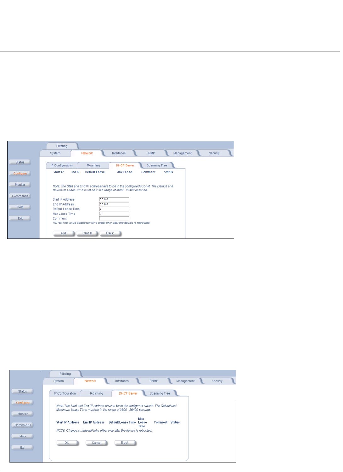
Configuration MeshMAX 5054 Series User Guide
Configuring the Subscriber Module
73
•Secondary DNS IP Address: The unit supplies this secondary DNS IP address in the DHCP response.
•Number of IP Pool Table Entries: The number of IP pool table entries is a read-only field that indicates the total
number of entries in the DHCP server IP Pool Table.
Add Entries to the DHCP Server IP Pool Table
You can add up to 20 entries in the IP Pool Table. An IP address can be added if the entry’s network ID is the same as the
network ID of the device.
NOTE: After adding entries, you must reboot the unit before the values take effect.
1. To add an entry click Add Table Entries.
2. Enter the following parameters and click Add:
•Start IP Address: Indicates the starting IP address that is used for assigning address to hosts on the Ethernet
side in the configured subnet.
•End IP Address: Indicates the ending IP address that is used for assigning address to hosts on the Ethernet side
in the configured subnet.
•Default Lease Time: Specifies the default lease time for IP addresses in the address pool. The value is
3600-86400 seconds.
•Max Lease Time: The maximum lease time for IP addresses in the address pool. The value is 3600-86400
seconds.
•Comment: The comment field is a descriptive field of up to 255 characters.
Edit/Delete Entries in the DHCP Server IP Pool Table Entries
1. Click Edit/Delete Table Entries to make changes
2. Enter your changes and click OK.
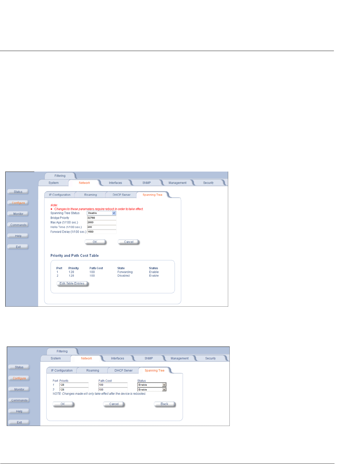
Configuration MeshMAX 5054 Series User Guide
Configuring the Subscriber Module
74
Spanning Tree (Bridge Mode Only)
NOTE: The unit must be in Bridge mode to configure Spanning Tree.
This protocol is executed between the bridges to detect and logically remove redundant paths from the network.
Spanning Tree can be used to prevent link-layer loops (broadcast is forwarded to all port where another device may
forward it and, finally, it gets back to this unit; therefore, it is looping). Spanning Tree can also be used to create redundant
links and operates by disabling links: hot standby customer is creating a redundant link without routing function.
If your network does not support Spanning Tree, be careful to avoid creating network loops between radios. For example,
creating a WDS link between two units connected to the same Ethernet network creates a network loop (if spanning tree
is disabled).
The Spanning Tree configuration options are advanced settings. Proxim recommends that you leave these parameters at
their default values unless you are familiar with the Spanning Tree protocol.
Click the Spanning Tree tab to change Spanning Tree values.
Edit/Disable Entries in the Priority and Path Cost Table
1. Click Edit Table Entries to make changes
2. Enter your changes and click OK.
IP Routes (Routing Mode only)
NOTE: The unit must be in Routing mode to configure IP Routes.
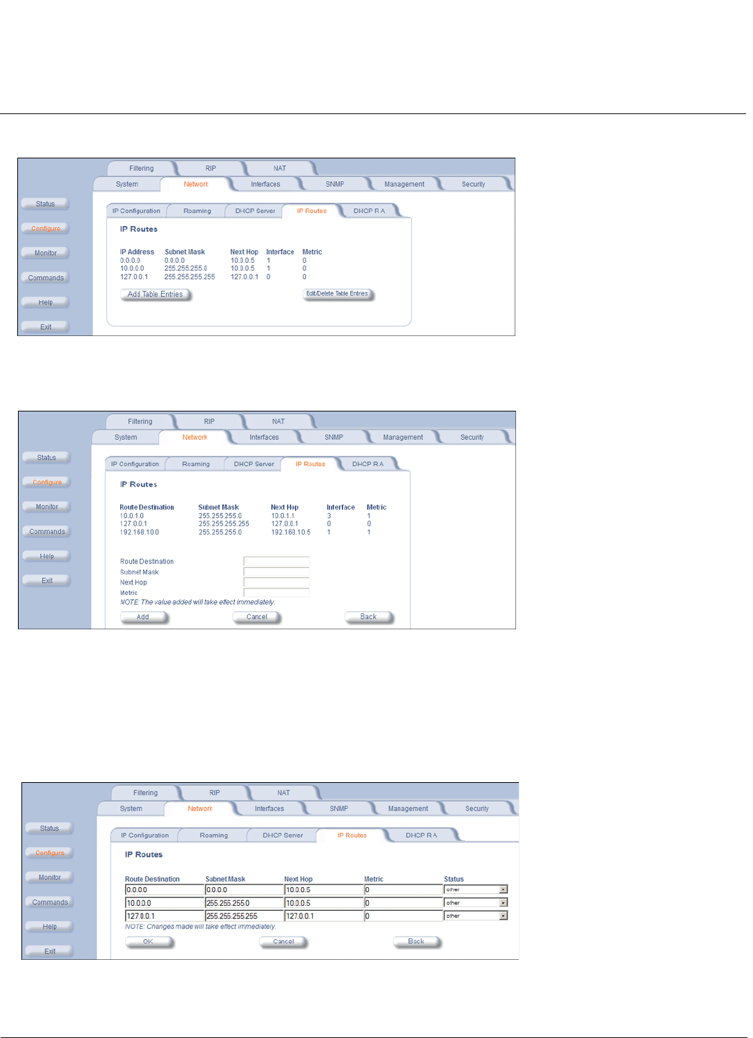
Configuration MeshMAX 5054 Series User Guide
Configuring the Subscriber Module
75
Click Configure > Network > IP Routes to configure.
Add IP Routes
1. Click the Add button; the following screen is displayed.
2. Enter the route information.
3. Click Add. The IP Address and Subnet Mask combination is validated for a proper combination.
NOTE: When adding a new entry, the IP address of the Route Destination must be in either the Ethernet subnet or in the
wireless subnet of the unit.
Edit/Delete IP Routes
1. Click the Edit/Delete Table Entries button to make changes to or delete existing entries.
2. Edit the route information.
3. Click OK. The IP address and subnet mask combination is validated for a proper combination.
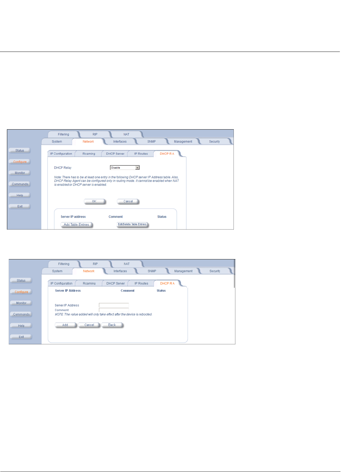
Configuration MeshMAX 5054 Series User Guide
Configuring the Subscriber Module
76
DHCP Relay Agent (Routing Mode Only)
NOTE: The unit must be in Routing mode to configure DHCP Relay Agent.
Click Configure > Network > DHCP RA to enable the Subscriber unit DHCP Relay Agent. When enabled, the DHCP
relay agent forwards DHCP requests to the set DHCP server. There must be at least one entry in the corresponding
Server IP Address table in order to enable the DHCP Relay Agent.
Note that DHCP Relay Agent parameters are configurable only in Routing mode. It cannot be enabled when NAT or
DHCP Server is enabled.
Add Entries to the DHCP Relay Agent Table
1. Click Add Table Entries; the following window is displayed:
2. Enter the Server IP Address and any optional comments, and click Add.
Edit/Delete Entries in the DHCP Relay Agent Table
1. Click Edit/Delete Table Entries. The following window is displayed:
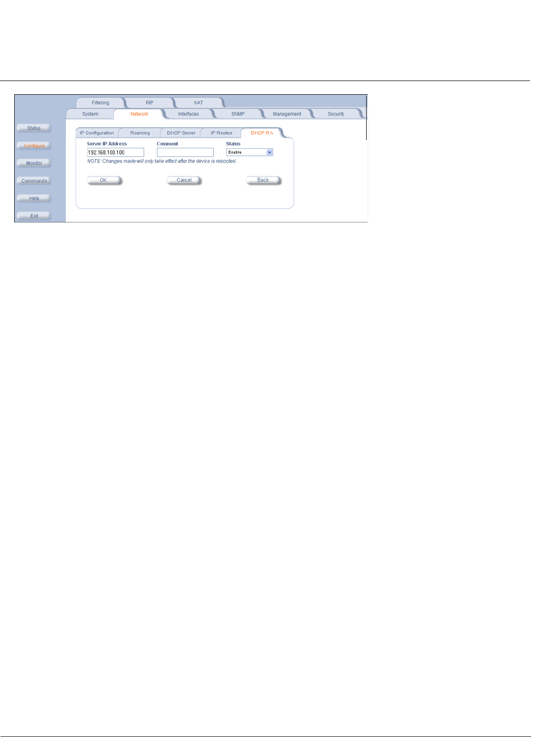
Configuration MeshMAX 5054 Series User Guide
Configuring the Subscriber Module
77
2. Enter your changes, and click OK.
Interface Parameters
Wireless
To configure the wireless interface, click Configure > Interfaces >Wireless.
SUs can be placed only in WORP Satellite mode. The Wireless Outdoor Router Protocol (WORP) is a polling algorithm
designed for wireless outdoor networks. WORP takes care of the performance degradation incurred by the so-called
“hidden-node” problem, which can occur when wireless LAN technology is used for outdoor building-to-building
connectivity. In this situation, when multiple radios send an RTS, if another radio is transmitting, it corrupts all data being
sent, degrading overall performance. The WORP polling algorithm ensures that these collisions cannot occur, which
increases the performance of the overall network significantly.
WORP dynamically adapts to the number of SUs that are active on the network and the amount of data they have
queued to send.
The mandatory parameters to configure for registration of the SU on a Base Station are:
• Network Name
• Base Station System Name (when used)
• Channel Frequency
• Encryption (when used)
•Network Secret
These and other parameters found on the SU’s Interfaces > Wireless page are described below.
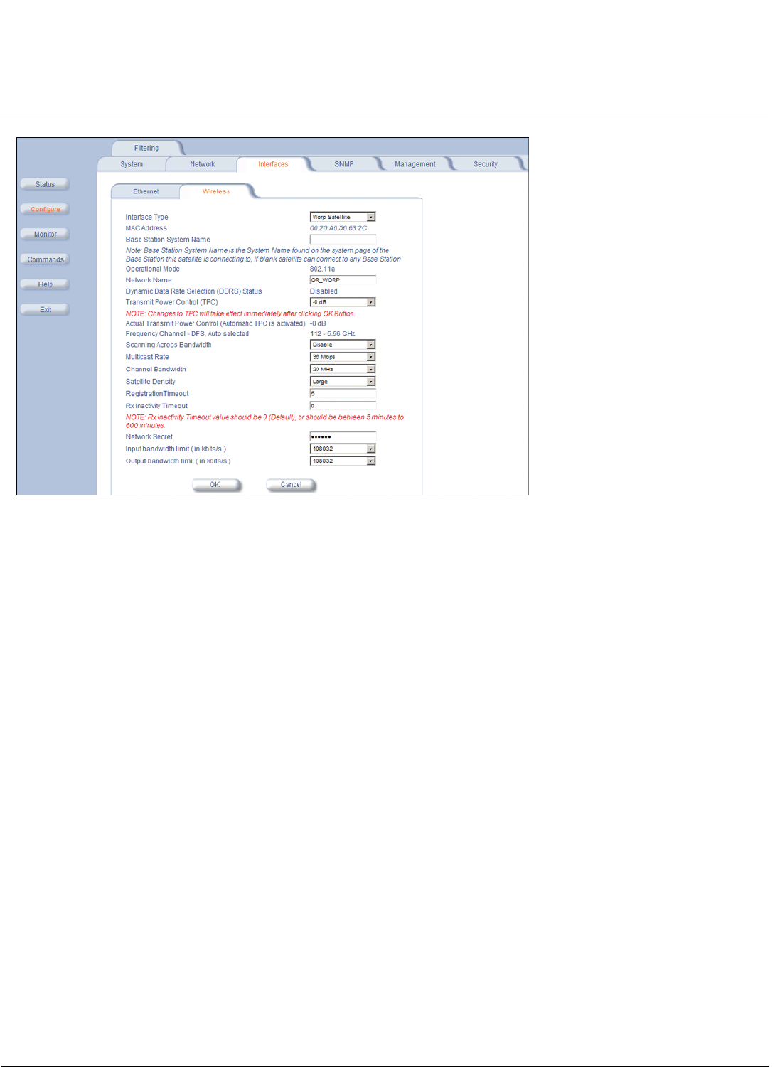
Configuration MeshMAX 5054 Series User Guide
Configuring the Subscriber Module
78
•Interface Type: The interface type is WORP Satellite.
•MAC Address: The factory-assigned MAC address of the unit. This is a read-only field.
•Base Station System Name: The name found on the system page of the BSU to which this SU is connecting. This
parameter can be used as an added security measure, and when there are multiple BSUs in the network and you
want an SU to register with only one when it may actually have adequate signal strength for either. The System Name
field is limited to a length of 32 bytes.
If the Base Station System Name is left blank on the SU, it can register with any BSU with a matching Network Name
and Network Secret.
•Operational Mode: This field indicates the operational mode of the unit, depending upon the specific Tsunami MP.11.
This operational mode cannot be changed as it is based upon a license file.
•Network Name: A Network Name is a name given to a network so that multiple networks can reuse the same
frequency without problems. An SU can only register to its base if it has the same Network Name. The Network Name
is one of the parameters that allow a Subscriber Unit to register on a Base Station. The Base Station System Name
and Frequency Channel also are parameters to guide the SU to the proper BSU on the network, but they provide no
security. Basic security is provided through encryption, as it causes none of the messages to be sent in the clear.
Further security is provided by mutual authentication of the BSU and SU using the Network Secret. The Network
Name can be 2 to 32 characters in length.
•Dynamic Data Rate Selection (DDRS) Status: For the WORP Satellite Mode,DDRS Status is read-only parameter
and its value is based upon the WORP Base to which this SU is associated.
When you enable or disable DDRS on the BSU, the BSU sends an announcement to the SUs and the SUs enable or
disable DDRS automatically.
•Transmit Power Control (TPC): By default, the unit lets you transmit at the maximum output power for the country or
regulatory domain and frequency selected. However, with Transmit Power Control (TPC), you can adjust the output
power of the unit to a lower level in order to reduce interference to neighboring devices or to use a higher gain
antenna without violating the maximum radiated output power allowed for your country/band. Also, some
countries/bands that require DFS also require the transmit power to be set to a 6 dB lower value than the maximum
allowed EIRP when link quality permits. You can see your unit’s current output power for the selected frequency in the
event log.

Configuration MeshMAX 5054 Series User Guide
Configuring the Subscriber Module
79
The event log shows the selected power for all data rates, so you must look up the proper data rate to determine the
actual power level.
NOTE: This feature only lets you decrease your output power; it does not let you increase your output power beyond
the maximum allowed defaults for your frequency and country.
Select one of the following options and click OK at the bottom of the window. Your original output power is adjusted
relative to the value selected. The new setting takes effect immediately without rebooting:
NOTE: 24 Mbps and lower modulation have maximum +16 dBm TX power, 36 Mbps has maximum +13 dBm TX
power, 48 Mbps has maximum +12 dBm TX power, and 54 Mbps has maximum +11 dBm TX power. Because
higher modulation has a lower maximum TX power, the total TPC range is smaller at a higher data rate.
Because the minimum TX power is equal for all data rates, each TPC selection has constant TX power for all
data rates except where the maximum TX power is limited.
•Actual Transmit Power Control: The configured Transmit Power Control setting.
•Enable Turbo Mode (Non-DFS US Only): Check this box to enable Turbo Mode. Turbo Mode is supported only in
the United States. Enabling turbo mode, in its current implementation, allows the unit to use two adjacent frequency
channels to transmit and receive a signal. By enabling turbo mode, the receive sensitivity improves by 4 dB for the 36
Mbps data rate and by 2 dB for the 24 Mbps data rate.
NOTE: The additional sensitivity is provided with the impact of using twice as much spectrum and thus increasing the
opportunity of interference and decreased ability for system collocation. Generally, Turbo mode is not
recommended except when the extra sensitivity is absolutely required.
•Frequency Channel: The frequency channel indicates the band center frequency the unit uses for communicating
with peers. This frequency channel can be set in several ranges, depending upon the regulatory domain. Refer to
Country Codes for Subscriber Module for channelization information. For countries in which DFS is not required, the
Frequency Channel list displays only the channels and frequencies allowed for the selected country/band.
For countries in which DFS is required, Frequency Channel is not configurable. Instead the channel is auto-selected
by the DFS process.
If All Channels 5 GHz is selected in the Country drop-down menu on the Configure > System page, any channel in
the 5 GHz range is manually selectable.
•Scanning Across Bandwidth: Enable this field if you want the SU to scan across the whole range of channel
bandwidths (5, 10, or 20 MHz, as available) with or without roaming enabled. Disable this field if you wish the SU to
scan only across its configured channel bandwidth.
•Multicast Rate: The rate at which data is to be transferred. All RF traffic between Subscriber unit units is multicast.
This drop down box is unavailable when DDRS is enabled.
The default data rate for the Subscriber unit is 36 Mbps. The SU must never be set to a lower data rate than the BSU,
because timeouts will occur at the BSU and communication will fail.
Selections for multicast rate are shown in the following table:
TPC Selection (dB) Maximum TX Power (dBm)
0 (default) 16
-3 13
-6 10
-9 7
-12 4
-15 1
-18 (minimum TPC level) 0
5 MHz 10 MHz 20 MHz 40 MHz
(Turbo Mode, Non-DFS US Only)
1.5 3 6 12

Configuration MeshMAX 5054 Series User Guide
Configuring the Subscriber Module
80
•Channel Bandwidth: This field is used to change the bandwidth. Values are 5 MHz, 10 MHz, or 20 MHz, as well as
40 MHz when Turbo mode is enabled.
NOTE: The 5 MHz channel bandwidth is not available when the selected country is UNITED STATES DFS.
•Satellite Density: The Satellite Density setting is a valuable feature for achieving maximum bandwidth in a wireless
network. It influences the receive sensitivity of the radio interface and improves operation in environments with a high
noise level. Reducing the sensitivity of the unit enables unwanted “noise” to be filtered out (it disappears under the
threshold).
You can configure the Satellite Density to be Large,Medium,Small,Mini, or Micro. The default value for this
setting is Large. The smaller settings are appropriate for high noise environments; a setting of Large would be for a
low noise environment.
A long distance link may have difficulty maintaining a connection with a small density setting because the wanted
signal can disappear under the threshold. Consider both noise level and distance between the peers in a link when
configuring this setting. The threshold should be chosen higher than the noise level, but sufficiently below the signal
level. A safe value is 10 dB below the present signal strength.
If the Signal-to-Noise Ratio (SNR) is not sufficient, you may need to set a lower data rate or use antennas with higher
gain to increase the margin between wanted and unwanted signals. In a point-to-multipoint configuration, the BSU
should have a density setting suitable for all of its registered SUs, especially the ones with the lowest signal levels
(longest links).
Take care when configuring a remote interface; check the available signal level first, using Remote Link Test.
WARNING: When the remote interface accidentally is set at too small a value and communication is lost, it
cannot be reconfigured remotely and a local action is required to bring the communication back.
Therefore, the best place to experiment with the level is at the unit that can be managed without
going through the link; if the link is lost, the setting can be adjusted to the correct level to bring
the link back.
Make your density selection from the drop-down menu. This setting requires a reboot of the unit. Sensitivity threshold
settings related to the density settings for the Subscriber unit are:
•Registration Timeout: This is the registration process time-out of an SU on a BSU. Default is 5 seconds.
•Rx Activity Timeout: This is the activity time-out of an SU on a BSU. Default is 0 seconds.
•Network Secret: A network secret is a secret password given to all nodes of a network. An SU can only register to a
BSU if it has the same Network Secret. The Network Secret is sent encrypted and can be used as a security option.
•Input / Output Bandwidth Limit: These parameters limit the data traffic received on the wireless interface and
transmitted to the wireless interface, respectively. Selections are in steps of 64 Kbps from 64 Kbps to 12 Mbps on the
5012-SUI and from 64 Kbps to 108,064 Kbps on the SU.
2.25 4.5 9 18
361224
4.5 9 18 36
6122448
9183672
12 24 48 96
13.5 27 54 108
Satellite Density Receive Sensitivity Threshold Defer Threshold
Large -95 dBm -62 dBm
Medium -86 dBm -62 dBm
Small -78 dBm -52 dBm
Mini -70 dBm -42 dBm
Micro -62 dBm -36 dBm
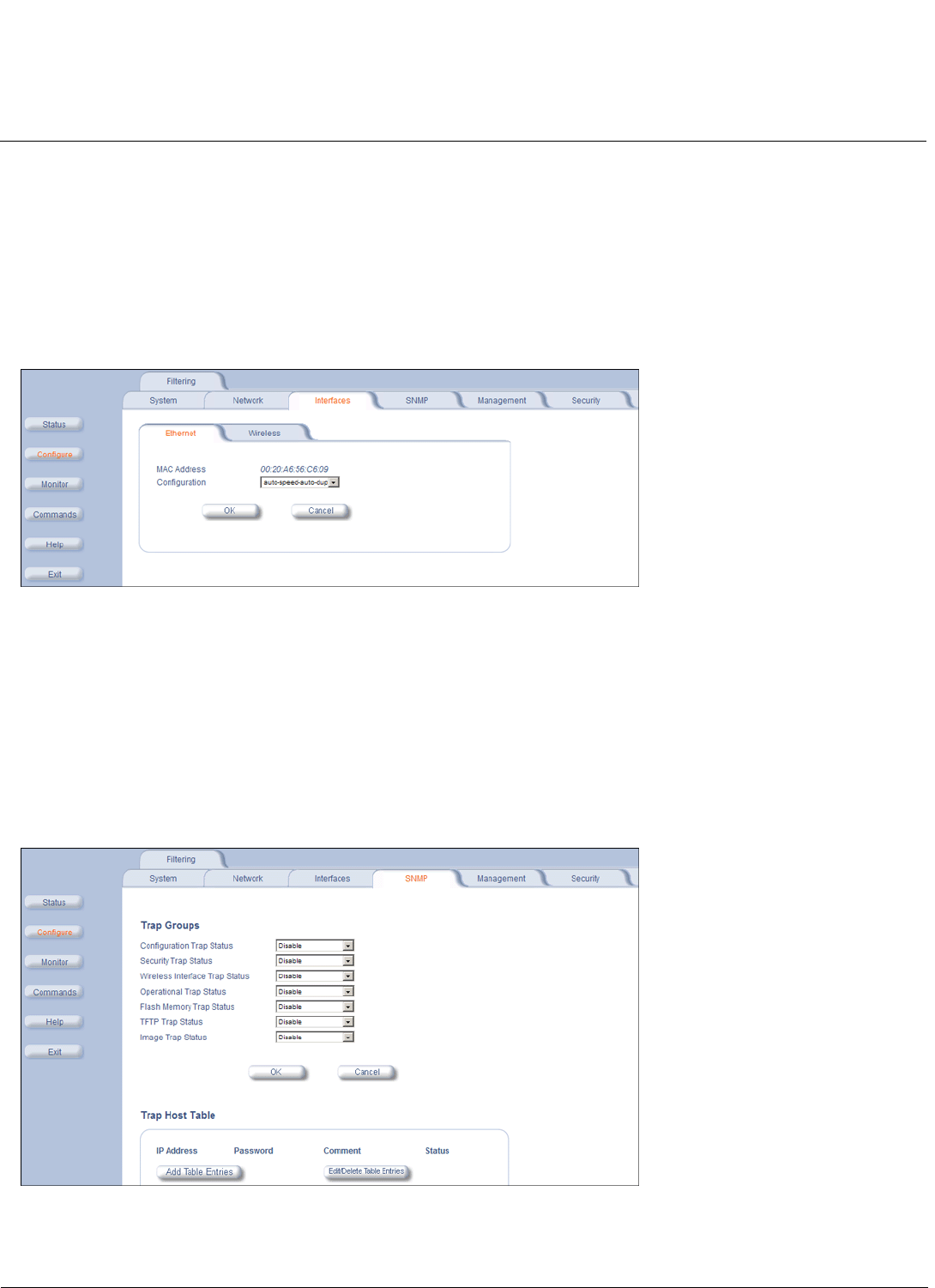
Configuration MeshMAX 5054 Series User Guide
Configuring the Subscriber Module
81
NOTE: For the 5012-SUI, the aggregate maximum bandwidth shared between input and output is 12 Mbps. If you
attempt to set the input/output bandwidth values so that the total exceeds 12 Mbps, the management interface
will automatically adjust the values to the available aggregate bandwidth of 12 Mbps. For example, the system
default is 6 Mbps for both input and output bandwidths. If you change the input to 8 Mbps, the management
interface will automatically adjust the output to 4 Mbps, for an aggregate bandwidth of 12 Mbps. The values
will not adjust automatically if the total is less than 12 Mbps.
Ethernet
To set the Ethernet speed, duplex mode, and input and output bandwidth limits, click Configure > Interfaces > Ethernet.
You can set the desired speed and transmission mode by clicking on Configuration. Select Auto-duplex (selects the
best transmission mode available when both sides are set to auto-select) from the settings for the type of Ethernet
transmission.
NOTE: The device may not wok, if there is a change in the configuration.
SNMP Parameters
Click Configure > SNMP to enable or disable trap groups, and to configure the SNMP management stations to which the
Subscriber unit sends system traps. See “Trap Groups” in the MeshMAX 5054 Subscriber Unit/MeshMAX 5054
Subscriber Unit/MeshMAX 5054 Subscriber Unit/Tsunami MP.11/QB.11 Reference Manual for a list of the system traps.
•Trap Groups: You can enable or disable different types of traps in the system. By default, all traps are enabled.
•Trap Host Table: This table shows the SNMP management stations to which the Subscriber unit sends system traps.
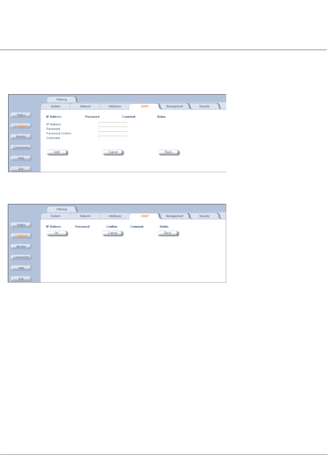
Configuration MeshMAX 5054 Series User Guide
Configuring the Subscriber Module
82
Trap Host Table
Add Entries to the Trap Host Table
Click the Add Table Entries button to add entries to the Trap Host Table.
Edit/Delete Entries to the Trap Host Table
Click the Edit/Delete Table Entries button to make changes to or delete existing entries.
Management Parameters
Use the Management tab to configure passwords and other service parameters.
Passwords
The Password tab lets you configure the SNMP, Telnet, and HTTP (Web Interface) passwords.
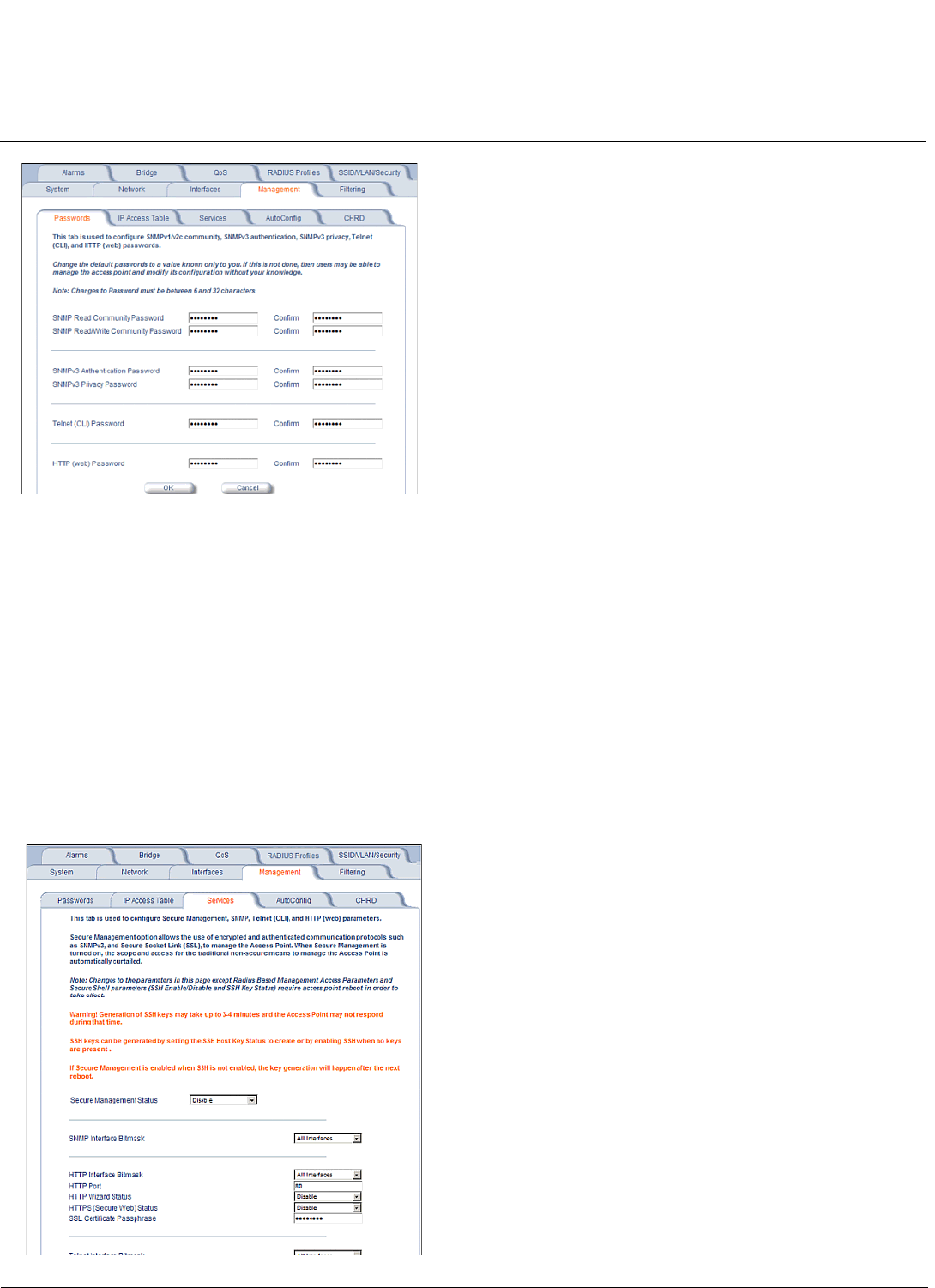
Configuration MeshMAX 5054 Series User Guide
Configuring the Subscriber Module
83
For all password fields, the passwords must be between 6 and 32 characters. Changes take effect immediately after you
click OK.
•SNMP Read Community Password: The password for read access to the Subscriber unit using SNMP. Enter a
password in both the Password field and the Confirm field. The default password is public.
•SNMP Read/Write Community Password: The password for read and write access to the Subscriber unit using
SNMP. Enter a password in both the Password field and the Confirm field. The default password is public.
•Telnet (CLI) Password: The password for the CLI interface. Enter a password in both the Password field and the
Confirm field. The default password is public.
•HTTP (Web) Password: The password for the Web browser HTTP interface. Enter a password in both the Password
field and the Confirm field. The default password is public.
Services
The Services tab lets you configure the SNMP, Telnet, HTTP, and Serial interface parameters. Changes to these
parameters require a reboot to take effect.

Configuration MeshMAX 5054 Series User Guide
Configuring the Subscriber Module
84
SNMP Configuration Settings
•SNMP Interface Bitmask: Configure the interface or interfaces (All Interfaces, Only Ethernet,Only Slot A, None)
from which you will manage the unit using SNMP. You also can select Disabled to prevent a user from accessing the
unit through SNMP.
HTTP Configuration Settings
•HTTP Interface Bitmask: Configure the interface or interfaces (All Interfaces, Only Ethernet,Only Slot A, None)
from which you will manage the unit through the Web interface. For example, to allow Web configuration through the
Ethernet network only, set HTTP Interface Bitmask to Ethernet. You can also select Disabled to prevent a user from
accessing the unit from the Web interface.
•HTTP Port: Configure the HTTP port from which you will manage the unit through the Web interface. By default, the
HTTP port is 80.
•HTTP Connections: The number of allowed HTTP connections (the maximum is 8).
Telnet Configuration Settings
NOTE: To use HyperTerminal for CLI access, make sure to check “Send line ends with line feeds” in the ASCII Setup
window (in the HyperTerminal window, click Properties; then select Setup > ASCII Setup. See “HyperTerminal
Connection Properties” in the MeshMAX 5054 Subscriber Unit/Tsunami MP.11/QB.11 Reference Manual for more
information).
•Telnet Interface Bitmask: Select the interface (Ethernet, Wireless, All Interfaces) from which you can manage the
unit through telnet. This parameter can also be used to disable telnet management.
•Telnet Port Number: The default port number for Telnet applications is 23. However, you can use this field if you want
to change the Telnet port for security reasons (but your Telnet application also must support the new port number you
select).
•Telnet Login Timeout (seconds): Enter the number of seconds the system is to wait for a login attempt. The unit
terminates the session when it times out. The range is 1 to 300 seconds; the default is 30 seconds.
•Telnet Session Timeout (seconds): Enter the number of seconds the system is to wait during a session while there is
no activity. The unit ends the session upon timeout. The range is 1 to 36000 seconds; the default is 900 seconds.
•Telnet Connections: The number of allowed Telnet connections (the maximum is 8).
Serial Configuration Settings
The serial port interface on the unit is enabled at all times. See “Serial Port” in the MeshMAX 5054 Subscriber
Unit/Tsunami MP.11/QB.11 Reference Manual for information about how to access the CLI interface through the serial
port. You can configure and view following parameters:
•Serial Baud Rate: Select the serial port speed (bits per second). Choose between 2400, 4800, 9600, 19200, 38400,
or 57600; the default Baud Rate is 9600.
•Serial Flow Control: Select either None (default) or Xon/Xoff (software controlled) data flow control. To avoid
potential problems when communicating with the unit through the serial port, Proxim recommends that you leave the
Flow Control setting at None (the default value).
•Serial Data Bits: This is a read-only field and displays the number of data bits used in serial communication (8 data
bits by default).
•Serial Parity: This is a read-only field and displays the number of parity bits used in serial communication (no parity
bits by default).
•Serial Stop Bits: This is a read-only field that displays the number of stop bits used in serial communication (1 stop
bit by default).
The serial port bit configuration is commonly referred to as 8N1.
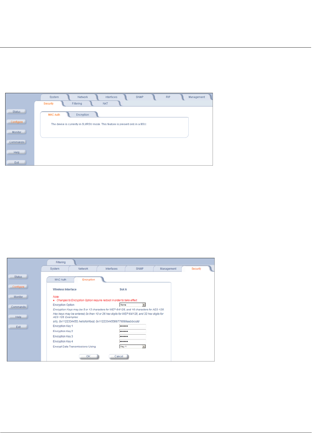
Configuration MeshMAX 5054 Series User Guide
Configuring the Subscriber Module
85
Security Parameters
MAC Authentication (BSU Only)
MAC authentication is available only for BSUs.
Encryption
NOTE: Be sure to set the encryption parameters and change the default passwords.
You can protect the wireless data link by using encryption. In addition to Wired Equivalent Privacy (WEP), the unit
supports Advanced Encryption Standard (AES) 128-bit encryption. To provide even stronger encryption, the AES CCM
Protocol is also supported.
Encryption keys can be 5 (64-bit), 13 (WEP 128-bit), or 16 (AES 128-bit) characters in length. Both ends of the wireless
data link must use the same parameter values.
Click Configure > Security >Encryption sub-tab to set encryption keys for the data transmitted and received by the
unit. Note that all devices in one network must use the same encryption parameters to communicate to each other.
Filtering Parameters
Overview
Click Configure > Filtering to configure packet filtering. Packet filtering can be used to control and optimize network
performance.
The Filtering feature can selectively filter specific packets based upon their Ethernet protocol type. Protocol filtering is
done at the Bridge layer.

Configuration MeshMAX 5054 Series User Guide
Configuring the Subscriber Module
86
Protocol filters are useful for preventing bridging of selected protocol traffic from one segment of a network to other
segments (or subnets). You can use this feature both to increase the amount of bandwidth available on your network and
to increase network security.
Increasing Available Bandwidth
It may be unnecessary to bridge traffic from a subnet using IPX/SPX or AppleTalk to a segment of the network with UNIX
workstations. By denying the IPX/SPX AppleTalk traffic from being bridged to the UNIX subnet, the UNIX subnet is free of
this unnecessary traffic.
Increasing Network Security
By bridging IP and IP/ARP traffic and blocking LAN protocols used by Windows, Novell, and Macintosh servers, you can
protect servers and client systems on the private local LAN from outside attacks that use those LAN protocols. This type
of filtering also prevents private LAN data from being bridged to an untrusted remote network or the Internet.
To prevent blocking your own access (administrator) to the unit, Proxim recommends that IP (0x800) and ARP (0x806)
protocols are always passed through.
Sample Use and Validation
Configure the protocol filter to let only IP and ARP traffic pass through the Subscriber unit (bridge) from one network
segment to another. Then, attempt to use Windows file sharing across the bridge. The file should not allow sharing; the
packets are discarded by the bridge.
Setting the ARP Filter
There may be times when you need to set the ARP or Multicast. Usually, this is required when there are many nodes on
the wired network that are sending ARP broadcast messages or multicast packets that unnecessarily consume the
wireless bandwidth. The goal of these filters is to allow only necessary ARP and multicast traffic through the 1.6 Mbps
wireless pipe.
The TCP/IP Internet Protocol Suite uses a method known as ARP (Address Resolution Protocol) to match a device's
MAC (Media Access Control) address with its assigned IP address. The MAC address is a unique 48-bit identifier
assigned to each hardware device at the factory by the manufacturer. The MAC address is commonly represented as 6
pairs of hexadecimal digits separated by colons. For example, a RangeLAN2 device may have the MAC address of
00:20:A6:33:ED:45.
When devices send data over the network (Ethernet, Token Ring, or wireless), they use the MAC address to identify a
packet's source and destination. Therefore, an IP address must be mapped to a MAC address in order for a device to
send a packet to particular IP address. In order to resolve a remote node's IP address with its MAC address, a device
sends out a broadcast packet to all nodes on the network. This packet is known as an ARP request or ARP broadcast
and requests that the device assigned a particular IP address respond to the sender with its MAC address.
Because ARP requests are broadcast packets, these packets are forwarded to wireless nodes by default, even if the
packet is not meant for a wireless node. As the number of nodes on a network backbone increases, so does the number
of ARP broadcasts that are forwarded to the wireless nodes. Many of these ARP broadcasts are unnecessary and can
consume valuable wireless bandwidth. On some networks, there are so many ARP broadcasts that the performance of
the wireless network will degrade due to the amount of bandwidth being consumed by these messages.
To reduce the number of ARP broadcasts that are forwarded to the wireless nodes, you can enable ARP filtering. When
enabled, the ARP Filter allows the unit to forward only those ARP broadcasts destined for an IP address that falls within
the range specified by the ARP Filter Network Address and the ARP Filter Subnet Mask. The ARP Filter performs a
logical AND function (essentially keeping what is the same and discarding what is different) on the IP address of the ARP
request and the ARP Filter Subnet Mask. It then compares the result of the logical AND to the ARP Filter Network
Address. If the two values match, the ARP broadcast is forwarded to the wireless network by the unit.
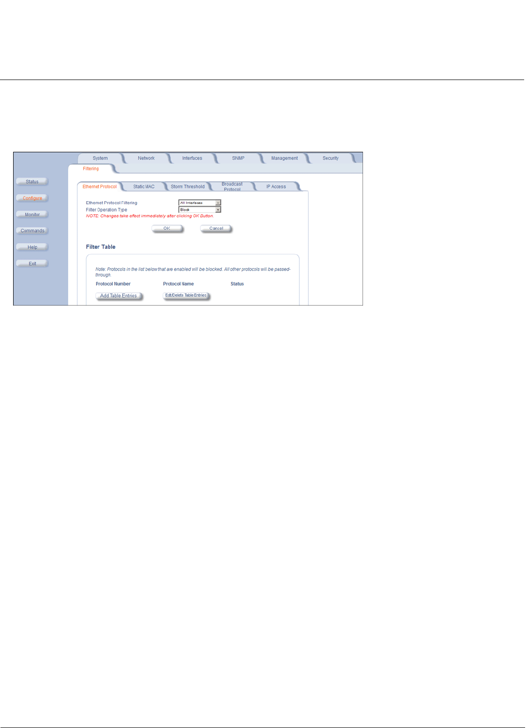
Configuration MeshMAX 5054 Series User Guide
Configuring the Subscriber Module
87
Ethernet Protocol
The Ethernet Protocol filter blocks or forwards packets based upon the Ethernet protocols they support. Click Configure
>Filtering >Ethernet Protocol to enable or disable certain protocols in the table. Entries can be selected from a
drop-down box.
Follow these steps to configure the Ethernet Protocol Filter:
1. Select the interfaces that will implement the filter from the Ethernet Protocol Filtering drop-down menu.
• Ethernet: Packets are examined at the Ethernet interface
• Wireless-Slot A or Wireless-Slot B: Packets are examined at the Wireless A or B interfaces
• All Interfaces: Packets are examined at both interfaces
• Disabled: The filter is not used
2. Select the Filter Operation Type.
• If set to Block, the bridge blocks enabled Ethernet Protocols listed in the Filter Table.
• If set to Passthru, only the enabled Ethernet Protocols listed in the Filter Table pass through the bridge.
3. Configure the Filter Table. See below.
NOTE: Entries must be enabled in order to be subject to the filter.
Add Entries to the Filter Table
1. Click Add Table Entries. You may add one of the supplied Ethernet Protocol Filters, or you may enter additional filters
by specifying the appropriate parameters:
• To add one of the supplied Ethernet Protocol Filters to the filter table:
– Select the appropriate filter from the Specify Common Protocol drop-down menu. Protocol Name and
Protocol Number fields will be filled in automatically.
– Click Add
• To add a new filter to the filter table:
– Enter the Protocol Number. See http://www.iana.org/assignments/ethernet-numbers for a list of protocol
numbers.
– Enter the Protocol Name.
– Click Add.
Edit/Delete Entries in the Filter Table
1. Click Edit and change the information, or select Enable, Disable, or Delete from the Status drop-down menu.

Configuration MeshMAX 5054 Series User Guide
Configuring the Subscriber Module
88
Static MAC Address Filtering
Overview
The Static MAC Address filter optimizes the performance of a wireless (and wired) network. When this feature is
configured properly, the unit can block traffic between wired devices on the wired (Ethernet) interface and devices on the
wireless interface based upon MAC address.
NOTE: The device on the wireless interface can be any device connected through the link. It can be directly connected to
the Ethernet interface of the peer unit, or it can be attached through multiple hops. The MAC address in the
packets arriving at the wireless interface is the important element.
The filter is an advanced feature that lets you limit the data traffic between two specific devices (or between groups of
devices based upon MAC addresses and masks) through the unit’s wireless interface. For example, if you have a server
on your network with which you do not want wireless clients to communicate, you can set up a static MAC filter to block
traffic between these devices. The Static MAC Filter Table performs bi-directional filtering. However, note that this is an
advanced filter and it may be easier to control wireless traffic through other filter options, such as Protocol Filtering.
Each MAC address or mask is comprised of 12 hexadecimal digits (0-9 and A-F) that correspond to a 48-bit identifier.
Each hexadecimal digit represents 4 bits (0 or 1).
Taken together, a MAC address/mask pair specifies an address or a range of MAC addresses that the unit looks for when
examining packets. The unit uses Boolean logic to perform an “and” operation between the MAC address and the mask
at the bit level. However, for most users, you do not need to think in terms of bits. It should be sufficient to create a filter
using only the hexadecimal digits 0 and F in the mask (where 0 is any value and F is the value specified in the MAC
address). A mask of 00:00:00:00:00:00 corresponds to all MAC addresses, and a mask of FF:FF:FF:FF:FF:FF:FF:FF
applies only to the specified MAC address.
For example, if the MAC address is 00:20:A6:12:54:C3 and the mask is FF;FF;FF;00:00:00, the unit examines the source
and destination addresses of each packet looking for any MAC address starting with 00:20:A6. If the mask is
FF;FF;FF;FF;FF;FF, the unit looks only for the specific MAC address (in this case, 00:20:A6:12:54:C3).
When creating a filter, you can configure the Wired parameters only, the Wireless parameters only, or both sets of
parameters. Which parameters to configure depends upon the traffic that you want to block:
• To prevent all traffic from a specific wired MAC address from being forwarded to the wireless network, configure only
the Wired MAC address and Wired mask (leave the Wireless MAC and Wireless mask set to all zeros).
• To prevent all traffic from a specific wireless MAC address from being forwarded to the wired network, configure only
the Wireless MAC and Wireless mask (leave the Wired MAC address and Wired mask set to all zeros).
• To block traffic between a specific wired MAC address and a specific wireless MAC address, configure all four
parameters.
Static MAC Filter Examples
Consider a network that contains a wired server and three wireless clients. The MAC address for each unit is as follows:
•Wired Server: 00:40:F4:1C:DB:6A
•Wireless Client 1: 00:02:2D:51:94:E4
•Wireless Client 2: 00:02:2D:51:32:12
•Wireless Client 3: 00:20:A6:12:4E:38
Prevent Two Specific Devices from Communicating
Configure the following settings to prevent the Wired Server and Wireless Client 1 from communicating:
•Wired MAC Address: 00:40:F4:1C:DB:6A
•Wired Mask: FF:FF:FF:FF:FF:FF
•Wireless MAC Address: 00:02:2D:51:94:E4

Configuration MeshMAX 5054 Series User Guide
Configuring the Subscriber Module
89
•Wireless Mask: FF:FF:FF:FF:FF:FF
Result: Traffic between the Wired Server and Wireless Client 1 is blocked. Wireless Clients 2 and 3 still can
communicate with the Wired Server.
Prevent Multiple Wireless Devices From Communicating With a Single Wired Device
Configure the following settings to prevent Wireless Clients 1 and 2 from communicating with the Wired Server:
•Wired MAC Address: 00:40:F4:1C:DB:6A
•Wired Mask: FF:FF:FF:FF:FF:FF
•Wireless MAC Address: 00:02:2D:51:94:E4
•Wireless Mask: FF:FF:FF:00:00:00
Result: When a logical “AND” is performed on the Wireless MAC Address and Wireless Mask, the result corresponds to
any MAC address beginning with the 00:20:2D prefix. Since Wireless Client 1 and Wireless Client 2 share the same
prefix (00:02:2D), traffic between the Wired Server and Wireless Clients 1 and 2 is blocked. Wireless Client 3 can still
communicate with the Wired Server since it has a different prefix (00:20:A6).
Prevent All Wireless Devices From Communicating With a Single Wired Device
Configure the following settings to prevent all three Wireless Clients from communicating with Wired Server:
•Wired MAC Address: 00:40:F4:1C:DB:6A
•Wired Mask: FF:FF:FF:FF:FF:FF
•Wireless MAC Address: 00:00:00:00:00:00
•Wireless Mask: 00:00:00:00:00:00
Result: The unit blocks all traffic between the Wired Server and all wireless clients.
Prevent A Wireless Device From Communicating With the Wired Network
Configure the following settings to prevent Wireless Client 3 from communicating with any device on the Ethernet:
•Wired MAC Address: 00:00:00:00:00:00
•Wired Mask: 00:00:00:00:00:00
•Wireless MAC Address: 00:20:A6:12:4E:38
•Wireless Mask: FF:FF:FF:FF:FF:FF
Result: The unit blocks all traffic between Wireless Client 3 and the Ethernet network.
Prevent Messages Destined for a Specific Multicast Group from Being Forwarded to the Wireless LAN
If devices on your Ethernet network use multicast packets to communicate and these packets are not required by your
wireless clients, you can set up a Static MAC filter to preserve wireless bandwidth. For example, if routers on your
network use a specific multicast address (such as 01:00:5E:00:32:4B) to exchange information, you can set up a filter to
prevent these multicast packets from being forwarded to the wireless network:
•Wired MAC Address: 01:00:5E:00:32:4B
•Wired Mask: FF:FF:FF:FF:FF:FF
•Wireless MAC Address: 00:00:00:00:00:00
•Wireless Mask: 00:00:00:00:00:00
Result: The unit does not forward any packets that have a destination address of 01:00:5E:00:32:4B to the wireless
network.
Static MAC Filter Configuration
Click Configure > Filtering > Static MAC to access the Static MAC Address filter.
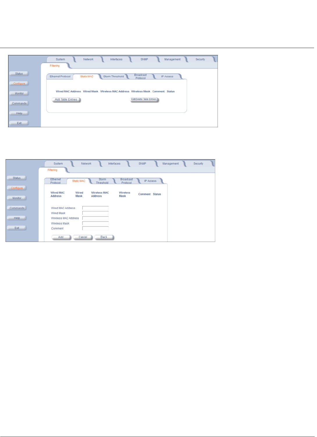
Configuration MeshMAX 5054 Series User Guide
Configuring the Subscriber Module
90
Add Enteries to the Static MAC Filter Table
To add the entries to Filter table, click the Add Table Entries button.
The following fields are may be configured or viewed:
•Wired MAC Address: Enter the MAC address of the device on the Ethernet network that you want to prevent from
communicating with a device on the wireless network.
•Wired Mask: Enter the appropriate bit mask to specify the range of MAC addresses to which this filter is to apply. To
specify only the single MAC address you entered in the Wired MAC Address field, enter 00:00:00:00:00:00 (all
zeroes).
•Wireless MAC Address: Enter the MAC address of the wireless device on the wireless interface that you want to
prevent from communicating with a device on the wired network.
•Wireless Mask: Enter the appropriate bit mask to specify the range of MAC addresses to which this filter is to apply.
To specify only the single MAC address you entered in the Wireless MAC Address field, enter 00:00:00:00:00:00 (all
zeroes).
•Comment: Enter related information.
•Status: The Status field can show Enable,Disable, or Delete.
After entering the data, click the Add button. The entry is enabled automatically when saved.
Edit/Delete Entries to the Static MAC Filter Table
To edit an entry, click Edit. To disable or remove an entry, click Edit and change the Status field from Enable to Disable
or Delete.
Storm Threshold
Click Configure > Filtering > Storm Threshold to use threshold limits to prevent broadcast/multicast overload.
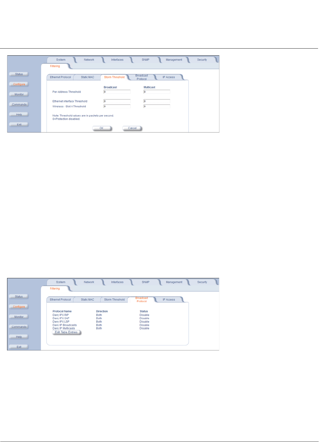
Configuration MeshMAX 5054 Series User Guide
Configuring the Subscriber Module
91
Storm Threshold is an advanced Bridge setup option that you can use to protect the network against data overload by
specifying:
• A maximum number of frames per second as received from a single network device (identified by its MAC address).
• An absolute maximum number of messages per port.
The Storm Threshold parameters let you specify a set of thresholds for each port of the Subscriber unit, identifying
separate values for the number of broadcast messages per second and multicast messages per second.
When the number of frames for a port or identified station exceeds the maximum value per second, the Subscriber unit
ignores all subsequent messages issued by the particular network device, or ignores all messages of that type.
The following parameters are configurable:
•Per Address Threshold: Enter the maximum allowed number of packets per second.
•Ethernet Threshold: Enter the maximum allowed number of packets per second.
•Wireless Slot A Threshold: Enter the maximum allowed number of packets per second.
Broadcast Protocol Filtering
Click Configure > Filtering > Broadcast Protocol to deny specific IP broadcast, IPX broadcast, and multicast traffic.
Click the Edit Table Entries button to display an editable window such as the following. You can configure whether this
traffic must be blocked for Ethernet to wireless, wireless to Ethernet, or both.
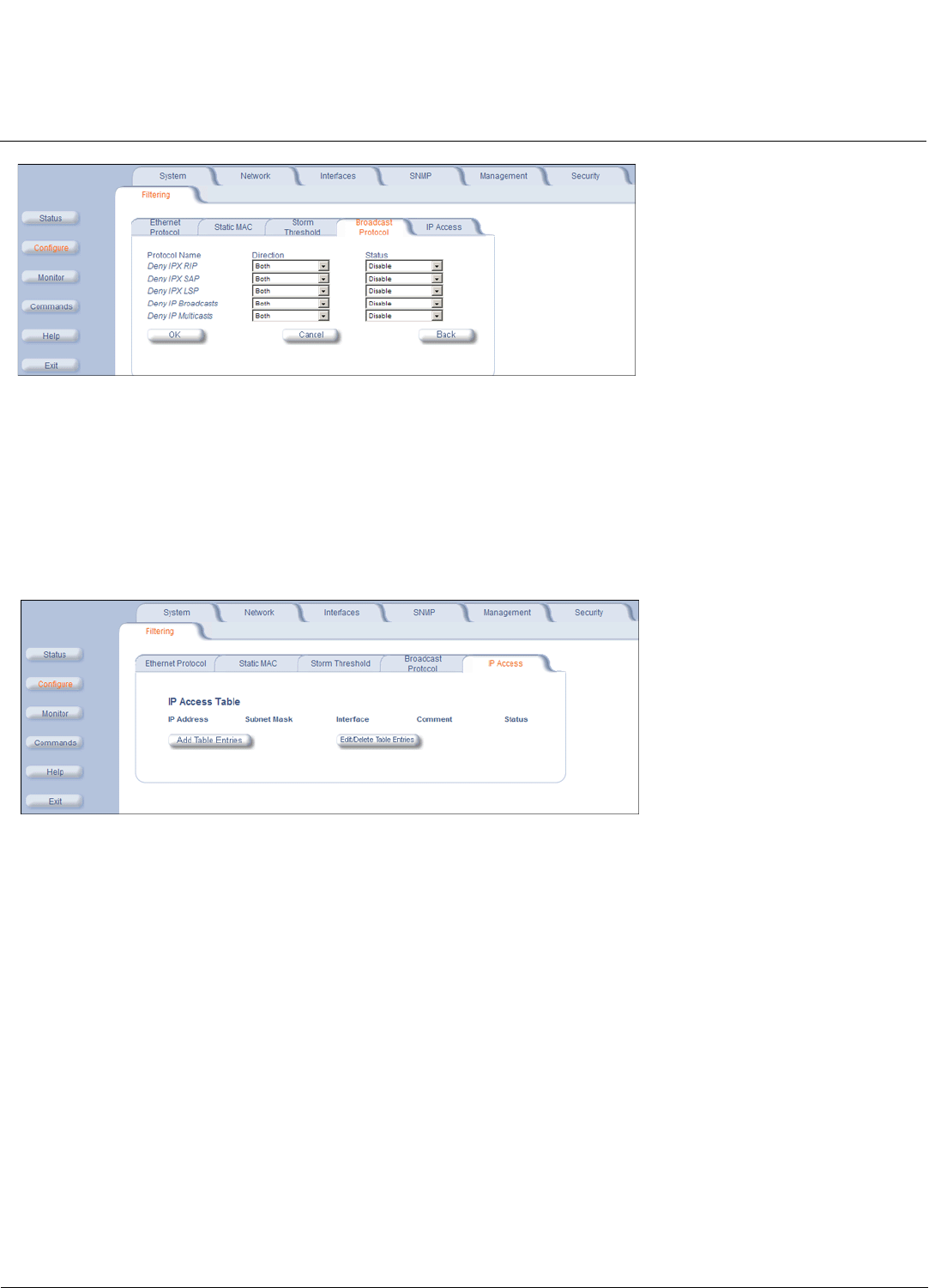
Configuration MeshMAX 5054 Series User Guide
Configuring the Subscriber Module
92
IP Access Table Filtering
Click Configure > Filtering > IP Access Table to limit in-band management access to the IP addresses or range of IP
addresses specified in the table.
For example, 172.17.23.0/255.255.255.0 allows access from all wireless stations with an IP address in the 172.17.23.xxx
range.
This feature applies to all management services (SNMP, HTTP, and CLI), except for CLI management over the serial
port.
Add Entries to the IP Access Table
To add an entry, click the Add Table Entries button, specify the IP address and mask of the wireless stations to which
you want to grant access, and click Add.
CAUTION: Ensure that the IP address of the management PC you use to manage the unit is within the first entry in the
table, as this filter takes effect immediately. Otherwise, you will have locked yourself out.
If you do lock yourself out, you may try to give the PC the correct IP address for management; otherwise you
must reset the unit via the CLI over the serial port.
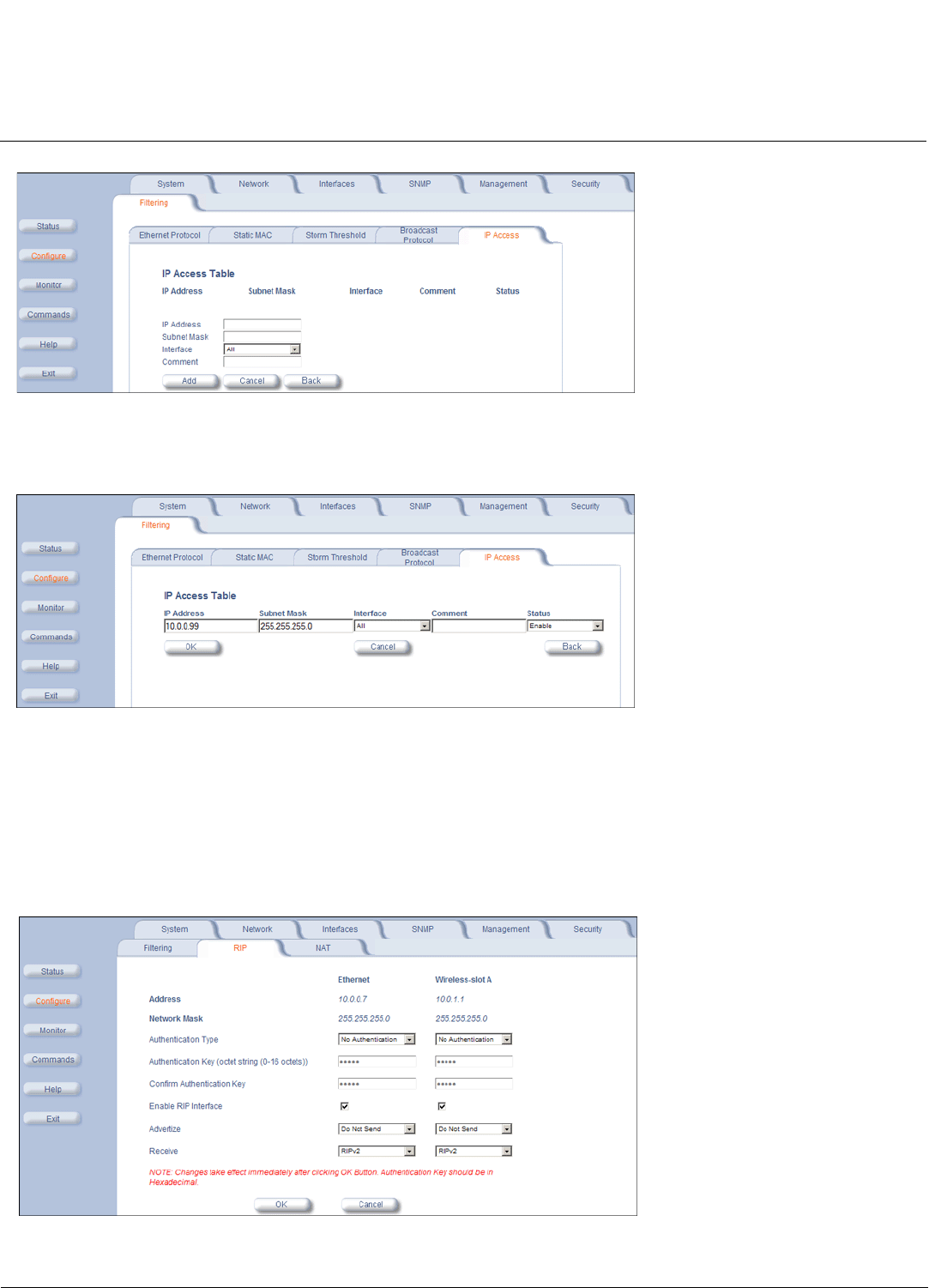
Configuration MeshMAX 5054 Series User Guide
Configuring the Subscriber Module
93
Edit/Delete Entries in the IP Access Table
To edit or delete table entries, click the Edit/Delete Table Entries button, make your changes, and click OK.
RIP Parameters (Routing Mode Only)
Routing Internet Protocol (RIP) is a dynamic routing protocol you can use to help automatically propagate routing table
information between routers. The unit can be configured as RIPv1, RIPv2, RIPv1 Compatible, or a combination of the
three versions while operating in Routing mode. In general, the unit’s RIP module is based upon RFC 1389.
NOTE: The RIP tab is available for SUs in Routing mode only. RIP is configurable only when the unit is in Routing
Mode and Network Address Translation (NAT) is disabled.
Note the following:

Configuration MeshMAX 5054 Series User Guide
Configuring the Subscriber Module
94
• RIPv2 is enabled by default when routing mode is selected.
• You may turn RIP off by clearing the Enable RIP Interface check box for the Ethernet or the wireless interface. Any
RIP advertisements that are received on the designated interface are ignored. All other options on the page are
dimmed.
• If the Enable RIP Interface check box is selected, the unit sends RIP requests and “listens” for RIP updates coming
from RIP-enabled devices advertising on the network. You may configure the Receive field for RIPv1, RIPv2, or a
combination of both. Although the unit receives and processes these updates, it does not further propagate these
updates unless configured to advertise RIP. Again, you may configure the Advertize field for RIPv1, RIPv2, or a
combination of both.
• The ability to enable or disable default route propagation is not user configurable. Once initialized, the Subscriber unit
uses its static default route and does not advertise this route in RIP updates. If another router on your network is
configured to advertise its default route, this route overwrites the static default route configured on the Subscriber unit.
The Subscriber unit then also propagates the new dynamic default route throughout the network.
Be aware that, once a dynamic default route is learned, it behaves just as any other dynamic route learned through RIP.
This means if the device sending the default route stops sending RIP updates, the default route times out and the unit
has no default route to the network. Workarounds for this condition include rebooting or re-entering a static default route.
In general, the best approach is to disable the propagation of default routes on the other routers in your network unless
you understand the risks.
The following table describes the properties and features of each version of RIP supported.
RIP Example
In the following example, assume that both the BSU and the SUs all are configured in Routing mode with RIP enabled to
send and receive on both the Ethernet and Wireless interfaces. The network converges through updates until each unit
has the following routing table:
RIPv1 RIPv2 RIPv1 Compatible
Broadcast Multicast Broadcast
No Authentication Authentication Authentication
Class routing Classless routing (VLSM) Classless routing (VLSM)
Distance-vector protocol Distance-vector protocol Distance-vector protocol
Metric-Hops Metric-Hops Metric-Hops
Maximum Distance 15 Maximum Distance 15 Maximum Distance 15
IGP IGP IGP
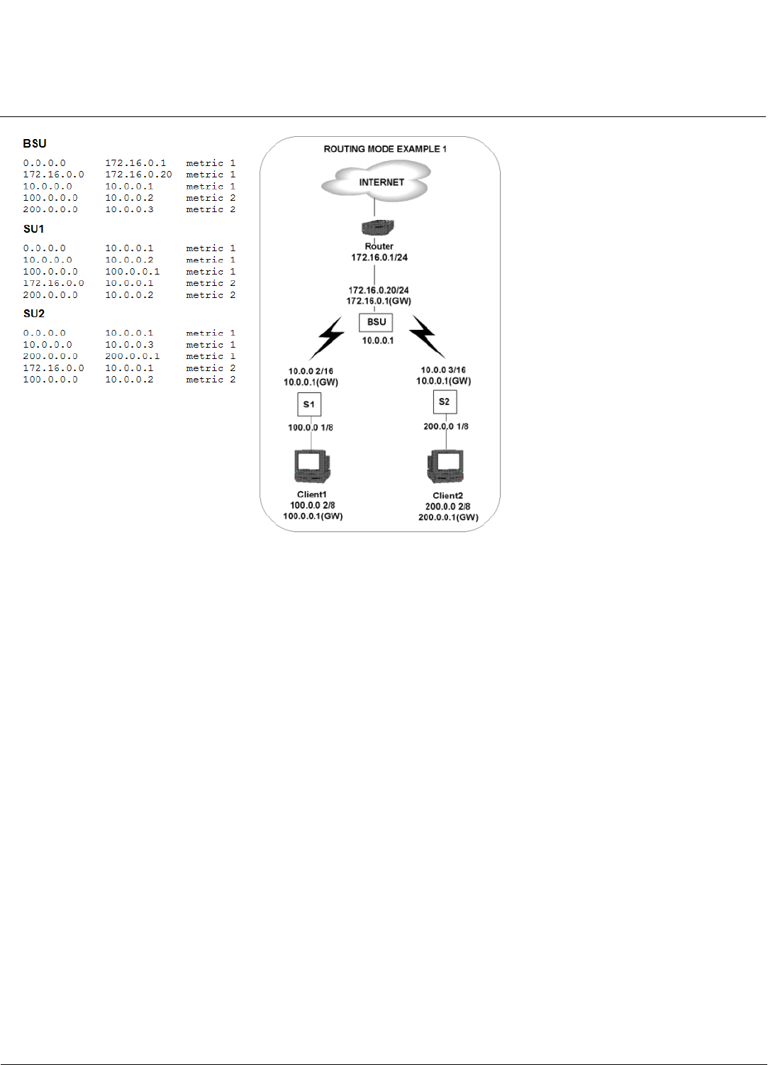
Configuration MeshMAX 5054 Series User Guide
Configuring the Subscriber Module
95
RIP Notes
• Ensure that routers on the same physical network are configured to use the same version of RIP.
• Routing updates occur every 30 seconds. It may take up to 3 minutes for a route that has gone down to timeout in a
routing table.
• RIP is limited to networks with 15 or fewer hops.
NAT (Routing Mode Only)
The NAT (Network Address Translation) feature lets hosts on the Ethernet side of the SU transparently access the public
network through the BSU. All hosts in the private network can have simultaneous access to the public network.
NOTE: The NAT tab is available for SUs in Routing mode only. The SU supports NAPT (Network Address Port
Translation) where all private IP addresses are mapped to a single public IP address, and does not support Basic
NAT (where private IP addresses are mapped to a pool of public IP addresses).
Both dynamic mapping (allowing private hosts to access hosts in the public network) and static mapping (allowing
public hosts to access hosts in the private network) are supported.
• In dynamic mapping, the SU maps the private IP addresses and its transport identifiers to transport identifiers of a
single Public IP address as they originate sessions to the public network. This is used only for outbound access.
• Static mapping is used to provide inbound access. The SU maps a private IP address and its local port to a fixed
public port of the global IP address. This is used to provide inbound access to a local server for hosts in the public
network. Static port mapping allows only one server of a particular type. Up to 1000 ports (500 UDP and 500 TCP) are
supported.
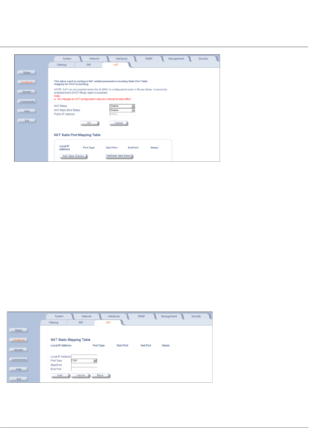
Configuration MeshMAX 5054 Series User Guide
Configuring the Subscriber Module
96
The following parameters are configurable:
NOTE: Changes to NAT parameters, including the NAT Static Port Mapping Table, require a reboot to take effect.
NOTE: When NAT is enabled, the DHCP Relay Agent feature is not supported (DHCP Relay Agent must be disabled
before NAT is enabled) and RIP updates are not sent or received. You can configure a DHCP server to allocate
IP addresses to hosts on the Ethernet side of the SU/ BSU.
•NAT Status: Enables or disables the NAT feature. NAT can be enabled only for SUs in Routing mode. The default is
disabled.
•NAT Static Bind Status: Enables or disables the NAT Static Bind status (static mapping) allowing public hosts to
access hosts in a private network. The default is disabled.
•Public IP Address: The NAT Public IP address is the wireless interface IP address.
NAT Static Port Mapping Table
Adding entries to the NAT Static Mapping Table lets configured hosts in a private address realm on the Ethernet side of
the SU access hosts in the public network using Network Address Port Translation (NAPT). Up to 1000 entries can be
configured (500 UDP ports and 500 TCP ports).
Add Entries to the NAT Static Mapping Table
1. Click the Add Table Entries button.
2. Enter the following information, and click Add:
• Enter the Local IP Address of the host on the Ethernet side of the SU.
• Select the Port Type:TCP,UDP, or Both.
• Enter the Start Port and End Port.
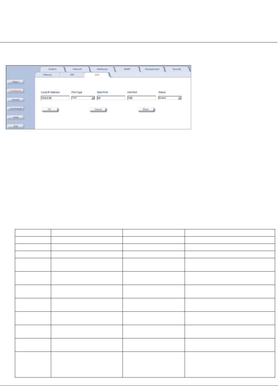
Configuration MeshMAX 5054 Series User Guide
Configuring the Subscriber Module
97
Edit/Delete Entries in the NAT Static Mapping Table
1. Click the Edit/Delete Table Entries button.
2. Enter your changes. To delete an entry, click the Status drop-down box and select Delete. Then Click OK.
Supported Session Protocols
The NAT feature supports the following session protocols for both inbound and outbound access with the required
support, applications, and limitations given in the following table.
Certain Internet applications require an Application Level Gateway (ALG) to provide the required transparency for an
application running on a host in a private network to connect to its counterpart running on a host in the public network. An
ALG may interact with NAT to set up state information, use NAT state information, modify application specific payload and
perform the tasks necessary to get the application running across address realms.
No more than one server of a particular type is supported within the private network behind the SU.
These VPN protocols are supported with their corresponding ALGs: IPsec, PPTP, L2TP.
The following session protocols are supported:
Protocol Support Applications Limitations
ICMP ICMP ALG Ping
FTP FTP ALG File transfer
H.323 H.323 ALG Multimedia conferencing
HTTP Port mapping for inbound
connection.
Web browser
TFTP Port mapping for inbound
connection.
File transfer
Telnet Port mapping for inbound
connection.
Remote login
CUSeeMe Port mapping for inbound and
outbound connection.
Video conferencing One user is allowed for video
conferencing
IMAP Port mapping for inbound
connection.
Mail
PNM Port mapping for inbound
connection.
Streaming media with
Real Player
POP3 Port mapping for inbound
connection.
E-mail
SMTP Port mapping for inbound
connection.
E-mail Mails with IP addresses of MTAs or
using IP addresses in place of FQDN
are not supported (requires SMTP
ALG).

Configuration MeshMAX 5054 Series User Guide
Configuring the Subscriber Module
98
RTSP Port mapping for inbound
connection.
Streaming audio/video
with Quick Time and Real
Player
ICQ Port mapping for inbound
connection.
Chat and file transfer Each host using ICQ needs to be
mapped for different ports.
IRC Port mapping for inbound
connection.
Chat and file transfer Each host using IRC needs to be
mapped for different ports.
MSN
Messenger
Port mapping for inbound and
outbound connection.
Conference and Share
files with Net meeting
Only one user is allowed for net
meeting.
Net2Phone Port mapping for inbound and
outbound connection.
Voice communication
IP Multicast Pass Through Multicasting
Stream works Port mapping for inbound
connection.
Streaming video
Quake Port mapping for inbound
connection.
Games When a Quake server is configured
within the private network behind a
SU, the SU cannot provide information
about that server on the public
network.
Also, certain Quake servers do not let
multiple users log in using the same IP
address, in which case only one
Quake user is allowed.
Protocol Support Applications Limitations
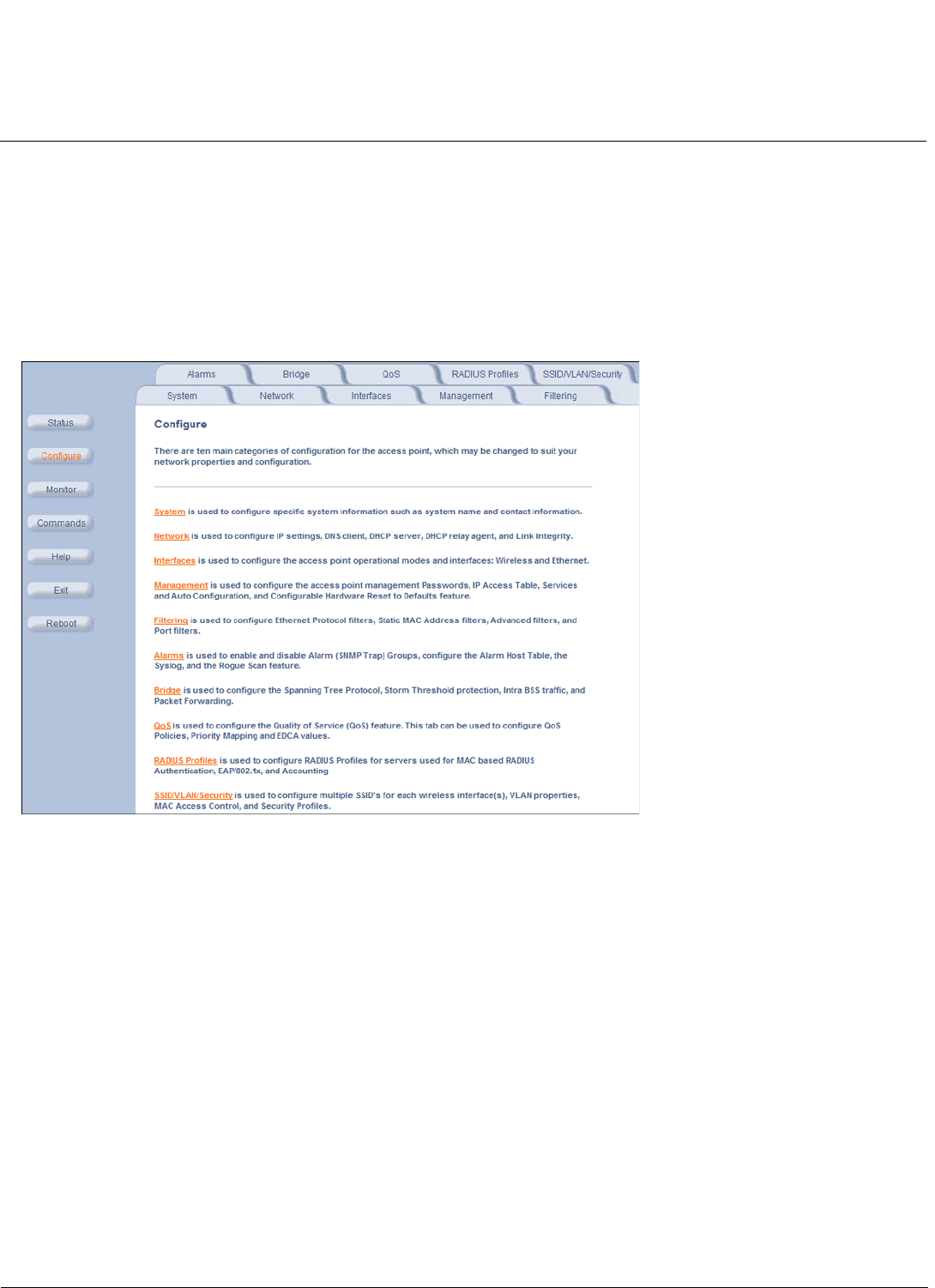
Configuration MeshMAX 5054 Series User Guide
Advanced Configuration of Mesh and Access Point Module
99
Advanced Configuration of Mesh and Access Point Module
To configure the AP using the HTTP/HTTPS interface, you must first log in to a web browser. See Logging In for
instructions.
You may also configure the AP using the command line interface. See CLI for Mesh and Access Point Module for more
information.
To configure the AP via HTTP/HTTPS:
3. Click the Configure button located on the left-hand side of the screen.
Figure 6-1 Configure Main Screen
4. Click the tab that corresponds to the parameter you want to configure. For example, click Network to configure the
Access Point’s TCP/IP settings.
Each Configure tab is described in the remainder of this chapter.
System
You can configure and view the following parameters within the System Configuration screen:
•Name: The name assigned to the AP.
•Country: The country in which the AP will be used. Note that some countries have two selectable options (one for
indoor use and one for outdoor use). Setting the country makes the AP automatically compliant with the rules of the
regulatory domain in which it is used by configuring the allowed frequency bands, channels, Dynamic Frequency
Selection status, Transmit Power Control status, and power levels.
NOTE: You must reboot the AP in order for country selection to take effect.
NOTE: Country selection is available only on APs with model numbers ending in -WD. If country selection is available,
however, it must be set before any interface parameters can be configured.
•Location: The location where the AP is installed.
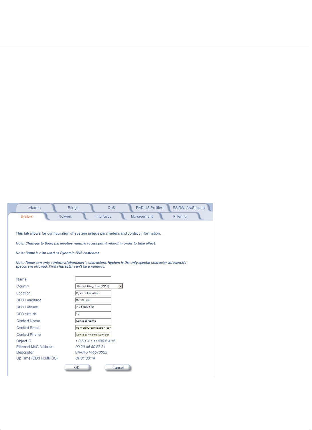
Configuration MeshMAX 5054 Series User Guide
Advanced Configuration of Mesh and Access Point Module
100
•GPS Longitude: The longitude at which the AP is installed. Enter the value in the format required by your network
management system. If using the ProximVision™ Network Management System (recommended), enter the value in
decimals (e.g., 78.4523).
•GPS Latitude: The latitude at which the AP is installed. Enter the value in the format required by your network
management system. If using the ProximVision™ Network Management System (recommended), enter the value in
decimals (e.g., 78.4523).
•GPS Altitude: The altitude at which the AP is installed. Enter the value in the format required by your network
management system. If using the ProximVision™ Network Management System (recommended), enter the value in
decimals (e.g., 78.4523).
•Contact Name: The name of the person responsible for the AP.
•Contact Email: The email address of the person responsible for the AP.
•Contact Phone: The telephone number of the person responsible for the AP.
•Object ID: This is a read-only field that displays the Access Point’s system object identification number; this
information is useful if you are managing the AP using SNMP.
•Ethernet MAC Address: This is a read-only field that displays the unique MAC (Media Access Control) address for
the Access Point’s Ethernet interface. The MAC address is assigned at the factory.
•Descriptor: This is a read-only field that reports the Access Point’s name, serial number, current image software
version, and current bootloader software version.
•Up Time: This is a read-only field that displays how long the Access Point has been running since its last reboot.
Figure 6-2 System Tab
Dynamic DNS Support
DNS is a distributed database mapping the user readable names and IP addresses (and more) of every registered
system on the Internet. Dynamic DNS is a lightweight mechanism which allows for modification of the DNS data of host

Configuration MeshMAX 5054 Series User Guide
Advanced Configuration of Mesh and Access Point Module
101
systems whose IP addresses change dynamically. Dynamic DNS is usually used in conjunction with DHCP for mapping
meaningful names to host systems whose IP addresses change dynamically.
Access Points provide DDNS support by adding the host name (option 12) in DHCP Client messages, which is used by
the DHCP server to dynamically update the DNS server.
Access Point System Naming Convention
The Access Point's system name is used as its host name. In order to prevent Access Points with default configurations
from registering similar host names in DNS, the default system name of the Access Point is uniquely generated. Access
Points generate unique system names by appending the last 3 bytes of the Access Point's MAC address to the default
system name.
The system name must be compliant with the encoding rules for host name as per DNS RFC 1123. According to the
encoding rules, the AP name:
• Can contain alphanumeric or hyphen characters only.
• Can contain up to 31 characters.
• Cannot start or end with a hyphen.
• Cannot start with a digit.
Network
The Network tab contains the following sub-tabs:
IP Configuration
This tab is used to configure the internet (TCP/IP) settings for the access point.
These settings can be either entered manually (static IP address, subnet mask, and gateway IP address) or obtained
automatically (dynamic).The DNS Client functionality can also be configured, so that host names used for configuring the
access point can be resolved to their IP addresses.
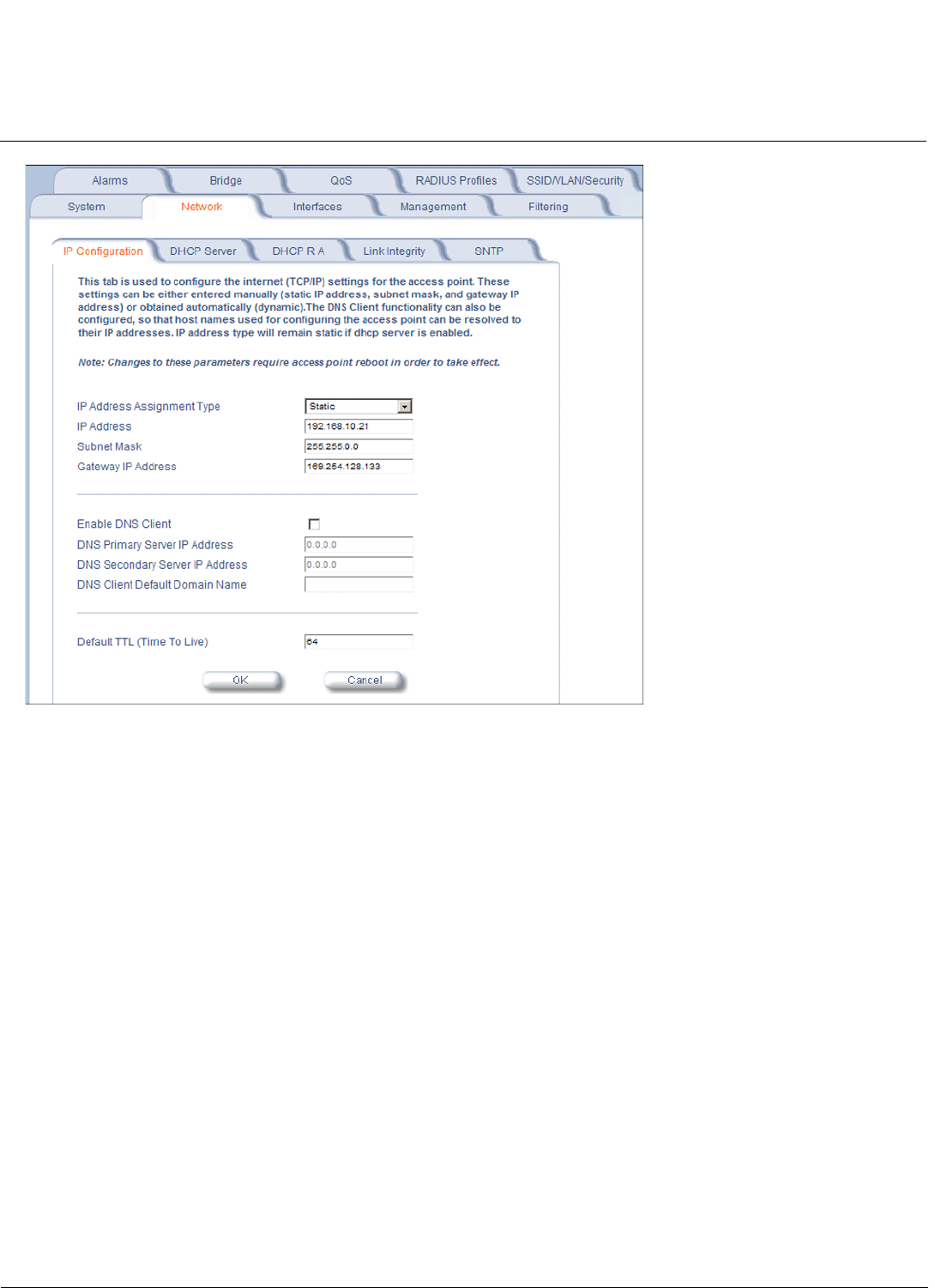
Configuration MeshMAX 5054 Series User Guide
Advanced Configuration of Mesh and Access Point Module
102
Figure 6-3 IP Configuration
You can configure and view the following parameters within the IP Configuration sub-tab:
NOTE: You must reboot the AP in order for any changes to the Basic IP or DNS Client parameters to take effect.
Basic IP Parameters
•IP Address Assignment Type: Set this parameter to Dynamic to configure the Access Point as a Dynamic Host
Configuration Protocol (DHCP) client; the Access Point will obtain IP settings from a network DHCP server
automatically during boot-up. If you do not have a DHCP server or if you want to manually configure the Access
Point’s IP settings, set this parameter to Static.
NOTE: IP Address Assignment Type must be set to Static if the AP will be configured as a Mesh AP.
•IP Address: The Access Point’s IP address. When IP Address Assignment Type is set to Dynamic, this field is
read-only and reports the unit’s current IP address. The Access Point will default to 169.254.128.132 if it cannot obtain
an address from a DHCP server.
•Subnet Mask: The Access Point’s subnet mask. When IP Address Assignment Type is set to Dynamic, this field is
read-only and reports the unit’s current subnet mask. The subnet mask will default to 255.255.0.0 if the unit cannot
obtain one from a DHCP server.
•Gateway IP Address: The IP address of the Access Point’s gateway. When IP Address Assignment Type is set to
Dynamic, this field is read-only and reports the IP address of the unit’s gateway. The gateway IP address will default to
169.254.128.133 if the unit cannot obtain an address from a DHCP server.
DNS Client
If you prefer to use host names to identify network servers rather than IP addresses, you can configure the AP to act as a
Domain Name Service (DNS) client. When this feature is enabled, the Access Point contacts the network’s DNS server to

Configuration MeshMAX 5054 Series User Guide
Advanced Configuration of Mesh and Access Point Module
103
translate a host name to the appropriate network IP address. You can use this DNS Client functionality to identify
RADIUS servers by host name.
•Enable DNS Client: Place a check mark in the box provided to enable DNS client functionality. Note that this option
must be enabled before you can configure the other DNS Client parameters.
•DNS Primary Server IP Address: The IP address of the network’s primary DNS server.
•DNS Secondary Server IP Address: The IP address of a second DNS server on the network. The Access Point will
attempt to contact the secondary server if the primary server is unavailable.
•DNS Client Default Domain Name: The default domain name for the Access Point’s network (for example,
“proxim.com”). Contact your network administrator if you need assistance setting this parameter.
Advanced
•Default TTL (Time to Live): Time to Live (TTL) is a field in an IP packet that specifies the number of hops, or routers
in different locations, that the request can travel before returning a failed attempt message. The Access Point uses the
default TTL for generated packets for which the transport layer protocol does not specify a TTL value. This parameter
supports a range from 0 to 255. By default, TTL is 64.
DHCP Server
If your network does not have a DHCP Server, you can configure the AP as a DHCP server to assign dynamic IP
addresses to Ethernet nodes and wireless clients.
NOTE: DHCP client functionality is not supported in a Mesh network.
CAUTION: Make sure there are no other DHCP servers on the network and do not enable the DHCP server without
checking with your network administrator first, as it could disrupt normal network operation. Also, the AP
must be configured with a static IP address before enabling this feature.
When the DHCP Server functionality is enabled, you can create one or more IP address pools from which to assign
addresses to network devices.
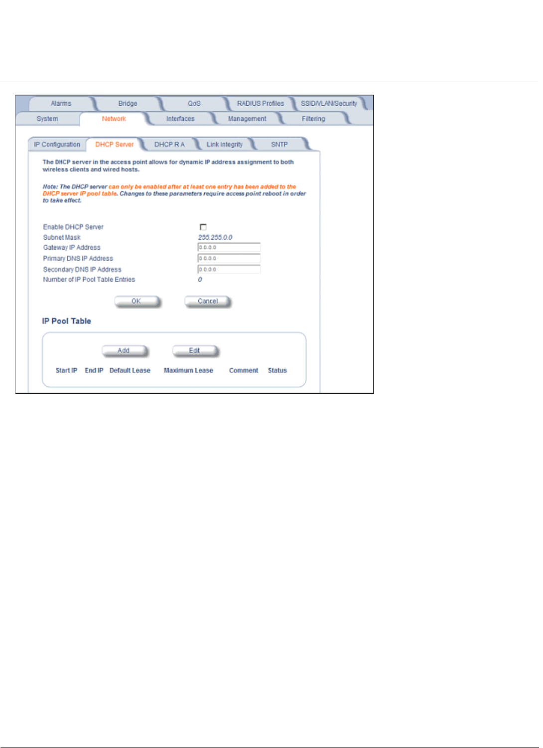
Configuration MeshMAX 5054 Series User Guide
Advanced Configuration of Mesh and Access Point Module
104
Figure 6-4 DHCP Server Configuration Screen
You can configure and view the following parameters within the DHCP Server Configuration screen:
NOTE: You must reboot the AP before changes to any of these DHCP server parameters take effect.
•Enable DHCP Server: Place a check mark in the box provided to enable DHCP Server functionality.
NOTE: You cannot enable the DHCP Server functionality unless there is at least one IP Pool Table Entry configured.
•Subnet Mask: This field is read-only and reports the Access Point’s current subnet mask. DHCP clients that receive
dynamic addresses from the AP will be assigned this same subnet mask.
•Gateway IP Address: The AP will assign the specified address to its DHCP clients.
•Primary DNS IP Address: The AP will assign the specified address to its DHCP clients.
•Secondary DNS IP Address: The AP will assign the specified address to its DHCP clients.
•Number of IP Pool Table Entries: This is a read-only field that reports the number of entries in the IP Pool Table.
•IP Pool Table Entry: This entry specifies a range of IP addresses that the AP can assign to its wireless clients. Click
Add to create a new entry. Click Edit to change an existing entry. Each entry contains the following fields:
– Start IP Address: The first IP address in the pool. IP addresses must be within the same subnet as the AP.
– End IP Address: The last IP address in the pool. IP addresses must be within the same subnet as the AP.
–Default Lease Time (optional): The default time value for clients to retain the assigned IP address. DHCP
automatically renews IP Addresses without client notification. This parameter supports a range between 3600 and
86400 seconds. The default is 86400 seconds. If this field is left blank, the default (86400) is used.
–Maximum Lease Time (optional): The maximum time value for clients to retain the assigned IP address. DHCP
automatically renews IP Addresses without client notification. This parameter supports a range between 3600 and
86400 seconds. The default is 86400 seconds. If this field is left blank, the default (86400) is used.
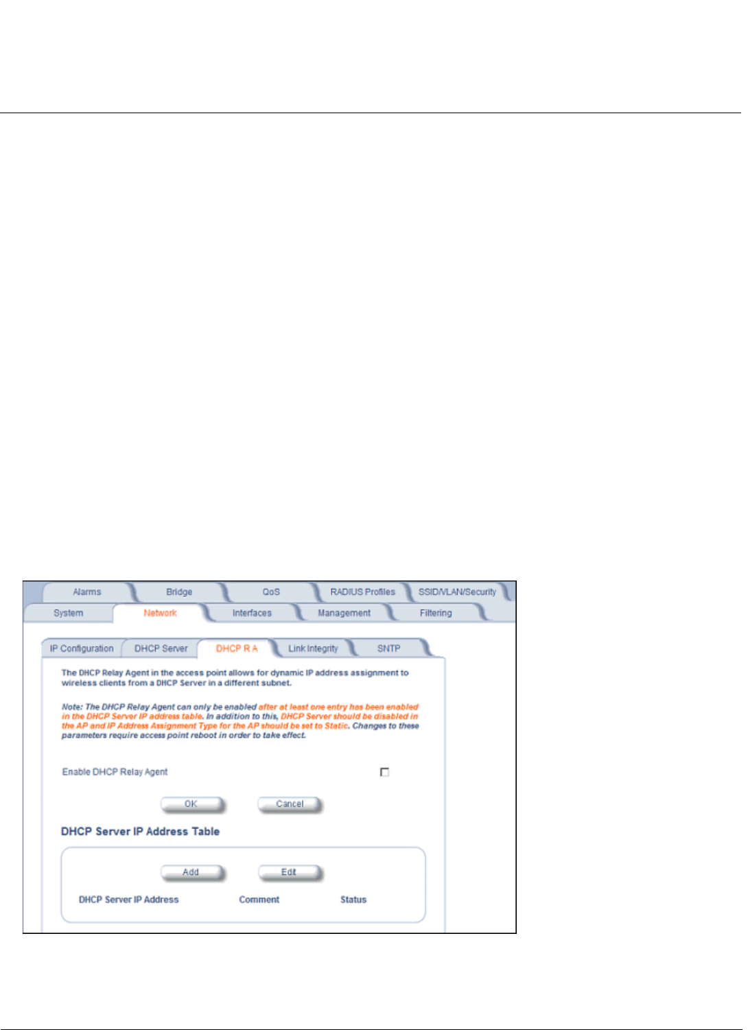
Configuration MeshMAX 5054 Series User Guide
Advanced Configuration of Mesh and Access Point Module
105
NOTE: The Default Lease Time cannot be larger than the Maximum Lease Time. If you set the Maximum Lease
Time, you should also set the Default Lease Time to ensure that the Default Lease Time is less than the
Maximum.
–Comment (optional)
–Status: IP Pools are enabled upon entry in the table. You can also disable or delete entries by changing this field’s
value.
NOTE: You must reboot the AP before changes to any of these DHCP server parameters take effect.
DHCP Relay Agent
When enabled, the DHCP relay agent forwards DHCP requests to the set DHCP server.
Click the Configure > Network > DHCP R A to configure DHCP relay agent servers and enable the DHCP relay agent.
NOTE: At least one DHCP server must be enabled before DHCP Relay Agent can be enabled.
NOTE: If the DHCP relay agent is unable to reach the external DHCP Server specified in the DHCP Server IP Address
Table, the requesting client will receive an IP address from the IP Pool table of the AP’s internal DHCP Server,
even if the internal DHCP Server is disabled.
NOTE: If a client requests an available IP address from the IP Pool table of the AP’s internal DHPC Server, the client will
receive this address, even if the DHCP server on the AP is disabled. To ensure that clients receive IP addresses
only from the DHCP Relay Agent, disable all entries in the IP Pool table of the AP’s internal DHCP server.
The DHCP Relay functionality of the AP supports Option 82 and sends the system name of the AP (as a NAS identifier)
as a sub-option of Option 82.
The AP makes a DHCP Request for lease renewal five minutes ahead of the expiration of the Rebinding time as
specified in the DHCP Offer from the DHCP server obtained during the last renewal.
Figure 6-5 DHCP Relay Agent
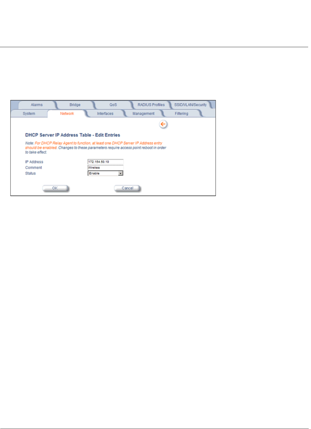
Configuration MeshMAX 5054 Series User Guide
Advanced Configuration of Mesh and Access Point Module
106
DHCP Server IP Address Table
The AP supports the configuration of a maximum of 10 server settings in the DHCP Relay Agents server table. At least
one server must be configured to enable DHCP Relay.
To add entries to the table of DHCP Relay Agents, click Add in the DHCP Server IP Address Table; to edit existing
entries, click Edit. The following window is displayed.
Figure 6-6 DHCP Server IP Address Table - Edit Entries
To add an entry, enter the IP Address of the DHCP Server and a comment (optional), and click OK.
To edit an entry, make changes to the appropriate entry. Enable or disable the entry by choosing Enable or Disable from
the Status drop-down menu, and click OK.
Link Integrity
The Link Integrity feature checks the link between the AP and any nodes on the backbone. These nodes are listed by IP
address in the Link Integrity IP Address Table. The AP periodically pings the nodes listed within the table. If the AP loses
network connectivity (that is, the ping attempts fail), the AP disables its wireless interface(s). Note that this feature does
not affect WDS links (if WDS links are configured and enabled).
NOTE: Link integrity cannot be configured when the AP is configured to function as a Mesh AP.
You can configure and view the following parameters within the Link Integrity Configuration screen:
•Enable Link Integrity: Place a check mark in the box provided to enable Link Integrity.
•Poll Interval (milliseconds): The interval between link integrity checks. Range is 500-15000 ms in increments of
500 ms; default is 500 ms.
•Poll Retransmissions: The number of times a poll should be retransmitted before the link is considered down.
Range is 0 to 255; default is 5.
•Target IP Address Entry: This entry specifies the IP address of a host on the network that the AP will periodically poll
to confirm connectivity. The table can hold up to five entries. By default, all five entries are set to 0.0.0.0. Click Edit to
update one or more entries. Each entry contains the following field:
– Target IP Address
– Comment (optional)
–Status: Set this field to Enable to specify that the Access Point should poll this device. You can also disable an
entry by changing this field’s value to Disable.
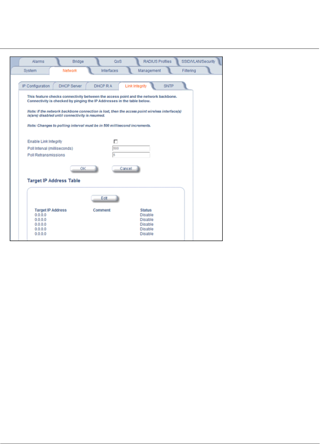
Configuration MeshMAX 5054 Series User Guide
Advanced Configuration of Mesh and Access Point Module
107
Figure 6-7 Link Integrity Configuration Screen
SNTP (Simple Network Time Protocol)
SNTP allows a network entity to communicate with time servers in the network/internet to retrieve and synchronize time
of day information. When this feature is enabled, the AP will attempt to retrieve the time of day information from the
configured time servers (primary or secondary), and, if successful, will update the relevant time objects in the AP.
Requests are sent every 10 seconds. If the AP fails to retrieve the information after three attempts, the AP will use the
system uptime and update the relevant time objects. If this feature is disabled, the user can manually configure the date
and time parameters.
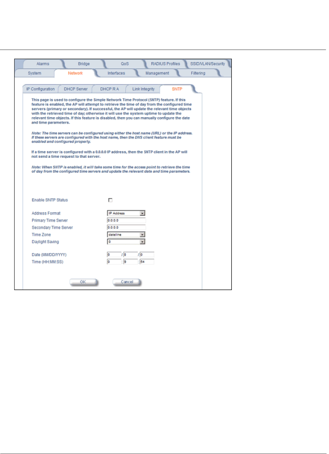
Configuration MeshMAX 5054 Series User Guide
Advanced Configuration of Mesh and Access Point Module
108
Figure 6-8 SNTP Configuration Screen
You can configure and view the following parameters within the SNTP screen:
•SNTP Status: Select Enable or Disable from the drop-down menu. The selected status will determine which of the
parameters on the SNTP screen are configurable.
NOTE: When SNTP is enabled, it will take some time for the AP to retrieve the time of day from the configured time
servers and update the relevant date and time parameters.
•Addressing Format: If SNTP is enabled, choose whether you will use the host name or the IP address to configure
the primary/secondary SNTP servers. If these servers are configured with the host name, the DNS client feature must
be enabled and configured properly.
•Primary Server Name or IP Address: If SNTP is enabled, enter the host name or IP address of the primary SNTP
server.
•Secondary Server Name or IP Address: If SNTP is enabled, enter the host name or IP address of the secondary
SNTP server.
•Time Zone: Select the appropriate time zone from the drop down menu.
•Daylight Savings Time: Select the number of hours to adjust for daylight savings time.
•Time and Date Information: When SNTP is disabled, the following time-relevant objects are manually configurable.
When SNTP is enabled, these objects are grayed out:

Configuration MeshMAX 5054 Series User Guide
Advanced Configuration of Mesh and Access Point Module
109
– Year: Enter the current year.
– Month: Enter the month in digits (1-12).
– Day: Enter the day in digits (1-31).
– Hour: Enter the hour in digits (0-23).
– Minutes: Enter the minutes in digits (0-59).
– Seconds: Enter the seconds in digits (0-59).
Interfaces
From the Interfaces tab, you configure the Access Point’s operational mode settings, power control settings, wireless
interface settings and Ethernet settings. You may also configure a Wireless Distribution System for AP-to-AP
communications. The Interfaces tab contains the following sub-tabs:
•Operational Mode
•Wireless-A (802.11a or 4.9 GHz Radio) and Wireless-B (802.11b/g Radio)
•Ethernet
•Mesh
NOTE: On APs with model numbers ending in -WD, the operating country must be selected on the System tab before
any of these sub-tabs are available.
Operational Mode
From this tab, you can configure and view the operational mode for the Wireless-A (802.11a radio or 4.9 GHz radio) or
Wireless-B (802.11b/g radio) interface.
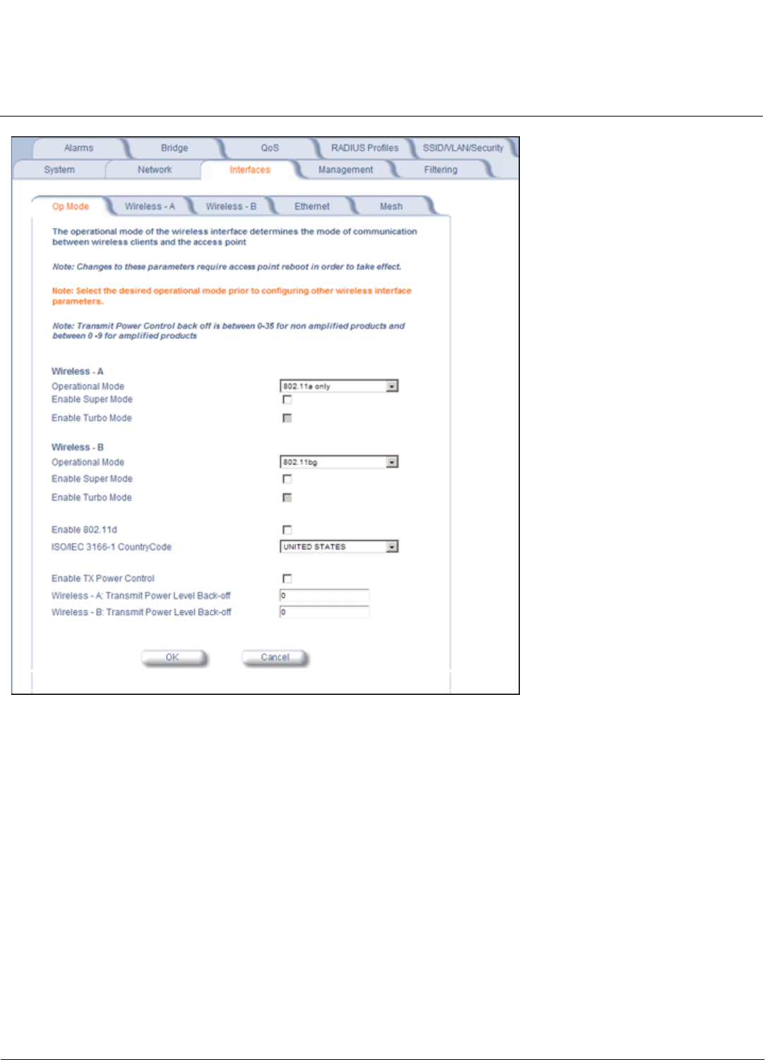
Configuration MeshMAX 5054 Series User Guide
Advanced Configuration of Mesh and Access Point Module
110
Figure 6-9 Operational Mode Screen
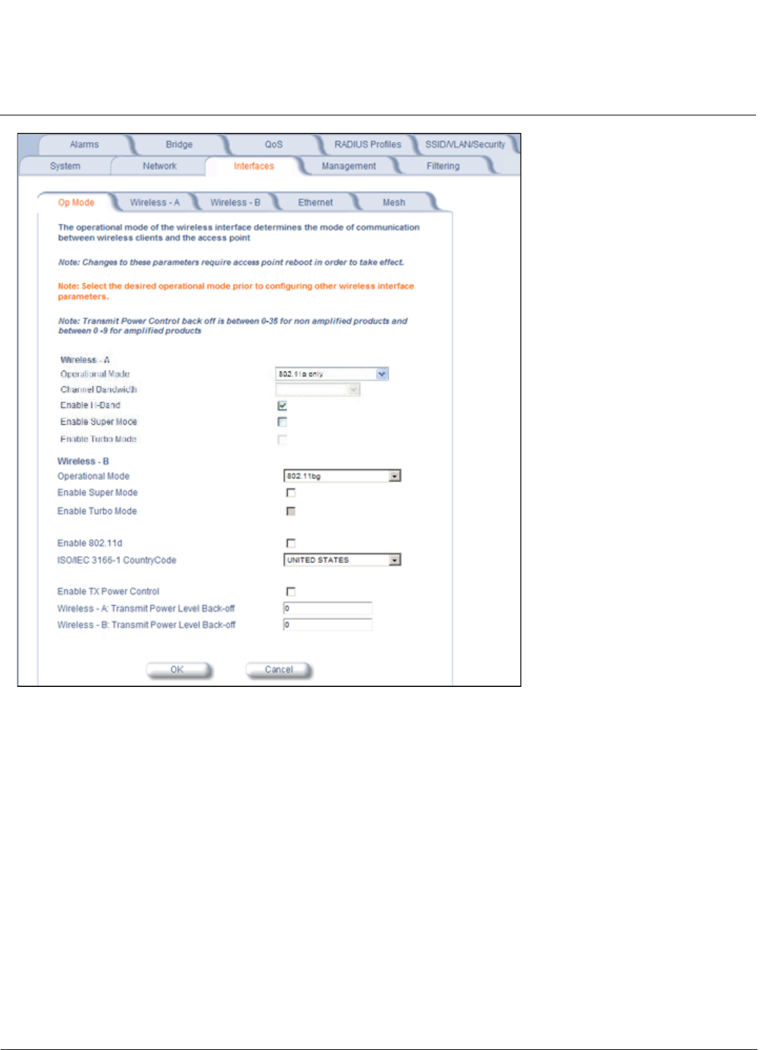
Configuration MeshMAX 5054 Series User Guide
Advanced Configuration of Mesh and Access Point Module
111
Figure 6-10 Operational Mode Screen (AP-4900MR-LR)
The Wireless-A interface operates in 802.11a mode on the Mesh and Access Point Module.
The Wireless-B interface can be configured to operate in the following modes:
•802.11b only mode: The radio uses the 802.11b standard only.
•802.11g only mode: The radio is optimized to communicate with 802.11g devices. This setting will provide the best
results if this radio interface will only communicate with 802.11g devices.
•802.11b/g mode: This is the default mode. Use this mode if you want to support a mix of 802.11b and 802.11g
devices.
•802.11g-wifi mode: The 802.11g-wifi mode has been defined for Wi-Fi testing purposes. It is not recommended for
use in your wireless network environment.
In general, you should use either 802.11g only mode (if you want to support 802.11g devices only) or 802.11b/g mode to
support a mix of 802.11b and 802.11g devices.

Configuration MeshMAX 5054 Series User Guide
Advanced Configuration of Mesh and Access Point Module
112
Enable H Band Support
In compliance with FCC regulations, Dynamic Frequency Selection is required in the middle frequency band (M band:
5.25 GHz - 5.25 Ghz) and high frequency band (H band: 5.470 GHz - 5.725 GHz). DFS is enabled automatically when
you use one or both of these frequency bands.
If the AP’s Wireless Card A is variant 2, 3, or 6, the M band channels are enabled by default, and DFS is performed
automatically and cannot be disabled. To add H band channels to the list of available channels, select Enable H Band
Support on the Op Mode page. When the H band is enabled, DFS is enabled automatically, and is performed on both M
and H band channels.
If the AP’s Wireless Card A is variant 8, 10, or 11, both M and H band channels are enabled automatically. DFS is
performed on both M and H band channels and cannot be disabled.
To identify your AP’s software variant, click Monitor > Version to view the Version tab.
For a full discussion of Dynamic Frequency Selection, see Dynamic Frequency Selection/Radar Detection (DFS/RD).
Super Mode and Turbo Mode
Super mode improves throughput between the access point and wireless clients that support this capability. For wireless
clients that support this capability the AP will negotiate and treat them accordingly, for other clients that do not support
super mode, the AP will treat them as normal wireless clients.
Super mode can be configured only when the wireless operational mode is one of the following:
• 802.11a only mode
• 802.11g only mode
• 802.11b/g mode
NOTE: Super mode is not available in 802.11b and 802.11g-wifi operational modes.
Super mode is supported in the 2.4 GHz and 5 GHz frequency bands in all regulatory domains.
Turbo mode is not supported on the Mesh and Access Point Module. This option will be greyed out.
IEEE 802.11d Support for Additional Regulatory Domains
The IEEE 802.11d specification allows conforming equipment to operate in more than one regulatory domain over time.
IEEE 802.11d support allows the AP to broadcast its radio’s regulatory domain information in its beacon and probe
responses to clients. This allows clients to passively learn what country they are in and only transmit in the allowable
spectrum. When a client enters a regulatory domain, it passively scans to learn at least one valid channel, i.e., a channel
upon which it detects IEEE Standard 802.11 frames.
The beacon frame contains information on the country code, the maximum allowable transmit power, and the channels to
be used for the regulatory domain.
The same information is transmitted in probe response frames in response to a client’s probe requests. Once the client
has acquired the information required to meet the transmit requirements of the regulatory domain, it configures itself for
operation in the regulatory domain.
On some AP models, the regulatory domain and associated parameters are automatically configured when a country is
selected on the System tab. On APs in which country selection is not available on the system tab, the regulatory domain
is pre-programmed into the AP prior to shipment. Depending on the regulatory domain, a default country code is chosen
that is transmitted in the beacon and probe response frames.
Configuring 802.11d Support
Perform the following procedure to enable 802.11d support and select the country code:
1. Click Configure > Interfaces > Operational Mode.
2. Select Enable 802.11d.

Configuration MeshMAX 5054 Series User Guide
Advanced Configuration of Mesh and Access Point Module
113
3. Select the Country Code from the ISO/IEC 3166-1 CountryCode drop-down menu.
NOTE: On APs with model numbers ending in -WD, this object is not configurable.
4. Click OK.
5. Configure Transmit Power Control and Transmit Power Level if required.
Transmit Power Control/Transmit Power Level
Transmit Power Control uses standard 802.11d frames to control transmit power within an infrastructure BSS (Basic
Service Set, or combination of AP and associated clients that can communicate to each other and/or to the backhaul
connection via the AP). This method of power control is considered to be an interim way of controlling the transmit power
of 802.11d enabled clients in lieu of implementation of 802.11h.
When an AP comes online, it automatically uses the maximum TX power allowed in the regulatory domain. The Transmit
Power Control feature lets the user manually lower the transmit power level by setting a “back-off” value between 0 and 9
dBm.
When Transmit Power Control is enabled, the transmit power level of the card in the AP is set to the maximum transmit
power level minus the back-off value. This power level is advertised in Beacon and Probe Response frames as the
802.11d maximum transmit power level.
When an 802.11d-enabled client learns the regulatory domain related information from Beacon and Probe Response
frames, it learns the power level advertised in Beacon and Probe response frames as the maximum transmit power of the
regulatory domain and configures itself to operate with that power level.
As a result, the transmit power level of the BSS is configured to the power level set in the AP (assuming that the BSS has
only 802.11d enabled clients and an 802.11d enabled AP).
NOTE: In FCC DFS-enabled bands, power control is adjusted from beacon information only.
In addition, ATPC (Automatic Transmit Power Control) is a feature to automatically adapt transmit power when the quality
of the link is more than sufficient to maintain a good communication with reduced transmit power. This feature is required
for FCC DFS. It works by monitoring the quality of the link and reducing the output power of the radio by up to 6 dB when
good link quality can still be achieved. When link quality reduces, the output power is automatically increased up to the
original power level to maintain a good link. For a full discussion of DFS, see Dynamic Frequency Selection/Radar
Detection (DFS/RD).
Configuring TX Power Control
1. Click Configure > Interfaces > Operational Mode.
2. Select Enable Transmit Power Control.
3. Enter the desired backoff from the maximum Transmit Power level (between 0 and 9 dBm) in the Wireless-A:
Transmit Power Level Back-Off or Wireless-B: Transmit Power Level Back-Off field.
4. Click OK.
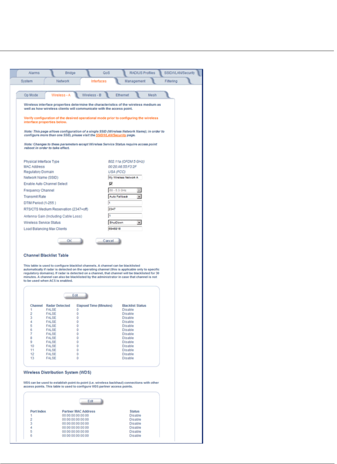
Configuration MeshMAX 5054 Series User Guide
Advanced Configuration of Mesh and Access Point Module
114
Wireless-A (802.11a or 4.9 GHz Radio) and Wireless-B (802.11b/g Radio)
Figure 6-11 Wireless Interface A

Configuration MeshMAX 5054 Series User Guide
Advanced Configuration of Mesh and Access Point Module
115
You can view and configure the following parameters for the Wireless-A and Wireless-B interfaces:
NOTE: You must reboot the Access Point before any changes to these parameters take effect.
•Physical Interface Type: For Wireless Interface A on the Mesh and Access Point Module, this field reports “802.11a
(OFDM 5 GHz).” On the AP-4900MR-LR, this field reports “Public Safety (OFDM 4.9 GHz).” For Wireless Interface B,
depending on the operational mode, this field reports:
– For 802.11b mode only: "802.11b (DSSS 2.4 GHz)"
– For 802.11g mode: "802.11g (OFDM/DSSS 2.4 GHz)"
– For 802.11b/g mode: "802.11g (OFDM/DSSS 2.4 GHz)"
– For 802.11g-wifi mode: "802.11g (OFDM/DSSS 2.4 GHz)"
NOTE: 802.11g-wifi has been defined for Wi-Fi testing purposes. It is not recommended for use in your wireless
network environment.
OFDM stands for Orthogonal Frequency Division Multiplexing; this is the name for the radio technology used by
802.11a/4.9 GHz devices. DSSS stands for Direct Sequence Spread Spectrum; this is the name for the radio
technology used by 802.11b devices.
•MAC Address: This is a read-only field that displays the unique MAC (Media Access Control) address for the Access
Point’s wireless interface. The MAC address is assigned at the factory.
•Regulatory Domain: Reports the regulatory domain for which the AP is certified. Not all features or channels are
available in all countries.
•Network Name (SSID): Enter a Network Name (between 1 and 32 characters long) for the primary wireless network.
You must configure each wireless client using this network to use this name as well. Additional SSIDs and VLANs may
be configured under Configure > SSID/VLAN/Security. Up to 16 SSID/VLANs may be configured per wireless
interface.
NOTE: Do not use quotation marks (single or double) in the Network Name; this will cause the AP to misinterpret the
name.
•Enable Auto Channel Select: When the Enable Auto Channel Select option is enabled, the AP scans the area for
other Access Points and selects a free or relatively unused communication channel. This helps prevent interference
problems and increases network performance. By default this feature is enabled. See Dynamic Frequency
Selection/Radar Detection (DFS/RD) for more information and Available Channels for a list of available channels.
NOTE: When an AP is configured to function as a Mesh AP, its channel will depend on the channel of its Mesh Portal.
•Frequency Channel: When Auto Channel Select is enabled, this field is read-only and displays the Access Point’s
current operating Channel. When Auto Channel Select is disabled, you can specify the Access Point’s operating
channel. If you decide to manually set the unit’s Channel, ensure that nearby devices do not use the same frequency
(unless you are setting up WDS links). Available channels vary based on regulatory domain. See Dynamic Frequency
Selection/Radar Detection (DFS/RD) for more information and Available Channels for a list of available channels.
NOTE: When an AP is configured to function as a Mesh AP, its channel will depend on the channel of its Mesh Portal.
•Transmit Rate: Use the drop-down menu to select a specific transmit rate for the AP. The values depend on the
Operational mode. Auto Fallback is the default setting; it allows the AP unit to select the best transmit rate based on
the cell size.
– For 802.11a only -- Auto Fallback, 6, 9, 12, 18, 24, 36, 48, 54 Mbits/s.
– For 4.9 GHz Public Safety mode, the transmit rate depends on the channel bandwidth selected:
• For operation in 10 MHz bandwidth: Auto Fallback, 3, 4.5, 6, 9, 12, 18, 24, 27 Mbits/s.
• For operation in 20 MHz bandwidth: Auto Fallback, 6, 9, 12, 18, 24, 36, 48, 54 Mbits/s.
– For 802.11b only -- Auto Fallback, 1, 2, 5.5, 11 Mbits/sec.
– For 802.11g only -- Auto Fallback, 6, 9, 12, 18, 24, 36, 48, 54 Mbits/sec
– For 802.11b/g -- Auto Fallback, 1, 2, 5.5, 6, 9, 11, 12, 18, 24, 36, 48, 54 Mbits/sec

Configuration MeshMAX 5054 Series User Guide
Advanced Configuration of Mesh and Access Point Module
116
– For 802.11g-wifi -- Auto Fallback, 1, 2, 5.5, 6, 9, 11, 12, 18, 24, 36, 48, 54 Mbits/sec
NOTE: 802.11g-wifi has been defined for Wi-Fi testing purposes. It is not recommended for use in your wireless
network environment.
•DTIM Period: The Deferred Traffic Indicator Map (DTIM) Period determines when to transmit broadcast and multicast
packets to all clients. If any clients are in power save mode, packets are sent at the end of the DTIM period. This
parameter supports a range between 1 and 255; it is recommended to leave the DTIM at its default value unless
instructed by technical support. Higher values conserve client battery life at the expense of network performance for
broadcast or multicast traffic.
•RTS/CTS Medium Reservation: This parameter affects message flow control and should not be changed under
normal circumstances. Range is 0 to 2347. When set to a value between 0 and 2347, the Access Point uses the
RTS/CTS mechanism for packets that are the specified size or greater. When set to 2347 (the default setting),
RTS/CTS is disabled. See RTS/CTS Medium Reservation for more information.
•Antenna Gain: This parameter modifies the sensitivity of the radio card when detecting radar signals in accordance
with Dynamic Frequency Selection/Radar Detection (DFS/RD) requirements. Given that the radar detection threshold
is fixed by the regulatory codes in the country of operation, and that a variety of antennas with different gains may be
attached to the unit, adjust this threshold to account for higher than expected antenna gains and avoid false radar
detection events. Set this parameter to a value between 0 and 35. The default value is 0.
•Wireless Service Status: Select Shutdown to shutdown the wireless service on a wireless interface, or to Resume
to resume wireless service. See Wireless Service Status for more information.
•Load Balancing Max Clients: Load balancing distributes clients among available access points. Enter a number
between 1 and 63 to specify the maximum number of clients to allow.
•Channel Blacklist Table: The Channel Blacklist table contains all available channels. It can be used to manually
blacklist channels, and it also reflects channels that have been automatically blacklisted by the Dynamic Frequency
Selection/Radar Detection (DFS/RD) function. See Channel Blacklist Table for configuration information.
•Wireless Distribution System: A Wireless Distribution system can be used to establish point-to-point (i.e. wireless
backhaul) connections with other access points. See Wireless Distribution System (WDS) for configuration
information.
Dynamic Frequency Selection/Radar Detection (DFS/RD)
In order to prevent interference with radar systems and other devices that occupy the 5 GHz band, 802.11a APs certified
in the ETSI, TELEC, FCC, and IC regulatory domains (see Affected Countries) and operating in the middle and high
frequency bands select an operating channel through a combination of Auto Channel Select (ACS) and Dynamic
Frequency Selection (DFS)/Radar Detection (RD).
During boot-up, ACS scans the available channels and selects the best channel. Once a channel is selected, the AP
performs a channel availability check for 60 seconds to ensure that the channel is not busy or occupied by radar, and
then commences normal operation. (In Canada, if the channel was previously blacklisted, the AP scans for 600 seconds
before commencing normal operation if the selected channel frequency is in the 5600 - 5650 MHz range). When the AP
enters normal operation, DFS works in the background to detect interference in that channel. If interference is detected,
the AP sends a trap, disassociates all clients, blacklists the channel, and reboots. After it reboots, ACS re-scans and
selects a better channel that is not busy and is free of radar interference.
If ACS is disabled, only channels in the lower, upper, and ISM frequency bands are available for use:
• 36: 5.180 GHz (default)
• 40: 5.200 GHz
• 44: 5.220 GHz
• 48: 5.240 GHz
• 149: 5.745 GHz
• 153: 5.765 GHz
• 157: 5.785 GHz

Configuration MeshMAX 5054 Series User Guide
Advanced Configuration of Mesh and Access Point Module
117
• 161: 5.805 GHz
• 165: 5.825 GHz
If you are using the unit in a country and band that require DFS, keep in mind the following:
• DFS is not a configurable parameter; it is always enabled and cannot be disabled.
• You cannot manually select the device’s operating channel; you must let the unit select the channel. You may make
channels unavailable by manually “blacklisting” them and preventing those channels being selected, in accordance
with local regulations or interference. You can also display the Channel Blacklist Table to view the channels that have
been blacklisted by the AP.
• In compliance with FCC regulations, the AP uses ATPC (Automatic Transmit Power Control) to automatically adapt
transmit power when the quality of the link is more than sufficient to maintain a good communication with reduced
transmit power. See Transmit Power Control/Transmit Power Level for more information.
DFS is required for three purposes:
1. Radar avoidance both at startup and while operational. To meet these requirements, the AP scans available
frequencies at startup. If a DFS enabled channel is busy or occupied with radar, the system will blacklist the channel
for a period of 30 minutes in accordance with FCC, IC, ETSI, and TELEC regulations. Once fully operational on a
frequency, the AP actively monitors the occupied frequency. If interference is detected, the AP blacklists the channel,
logs a message and rescans to find a new frequency that is not busy and is free of radar interference.
2. Guarantee the efficient use of available frequencies by all devices in a certain area. To meet this requirement, the AP
scans each available frequency upon startup and selects a frequency based upon the least amount of noise and
interference detected. This lets multiple devices operate in the same area with limited interference. This procedure is
done only at startup; if another UNII device comes up on the same frequency, the AP does not detect this or rescan
because of it. It is expected that other devices using these frequencies also are in compliance with country
regulations, so this should not happen.
3. Uniform Channel Spreading. To meet this requirement, the AP randomly selects its operating channel from the
available channels with least interference.
Affected Countries
Japan is certified in the TELEC regulatory domain, Canada is certified in the IC regulatory domain, and the USA is
certified in the FCC regulatory domain for operation in the 5 GHz band.
The following countries are certified in the ETSI regulatory domain for operation in the 5 GHz band:
RTS/CTS Medium Reservation
The 802.11 standard supports optional RTS/CTS communication based on packet size. Without RTS/CTS, a sending
radio listens to see if another radio is already using the medium before transmitting a data packet. If the medium is free,
the sending radio transmits its packet. However, there is no guarantee that another radio is not transmitting a packet at
the same time, causing a collision. This typically occurs when there are hidden nodes (clients that can communicate with
the Access Point but are out of range of each other) in very large cells.
–Austria –Greece –Norway
– Belgium – Hungary – Poland
– Czech Republic – Ireland – Portugal
–Cyprus –Italy –Spain
– Denmark – Latvia – Sweden
– Estonia – Lithuania – Switzerland
– Finland – Luxembourg – UK
– France – Malta
– Germany – Netherlands

Configuration MeshMAX 5054 Series User Guide
Advanced Configuration of Mesh and Access Point Module
118
When RTS/CTS occurs, the sending radio first transmits a Request to Send (RTS) packet to confirm that the medium is
clear. When the receiving radio successfully receives the RTS packet, it transmits back a Clear to Send (CTS) packet to
the sending radio. When the sending radio receives the CTS packet, it sends the data packet to the receiving radio. The
RTS and CTS packets contain a reservation time to notify other radios (including hidden nodes) that the medium is in use
for a specified period. This helps to minimize collisions. While RTS/CTS adds overhead to the radio network, it is
particularly useful for large packets that take longer to resend after a collision occurs.
RTS/CTS Medium Reservation is an advanced parameter and supports a range between 0 and 2347 bytes. When set to
2347 (the default setting), the RTS/CTS mechanism is disabled. When set to 0, the RTS/CTS mechanism is used for all
packets. When set to a value between 0 and 2347, the Access Point uses the RTS/CTS mechanism for packets that are
the specified size or greater. You should not need to enable this parameter for most networks unless you suspect that the
wireless cell contains hidden nodes.
Wireless Service Status
The user can shut down (or resume) the wireless service on the wireless interface of the AP through the CLI, HTTP, or
SNMP interface. When the wireless service on a wireless interface is shut down, the AP will:
• Stop the AP services to wireless clients connected on that wireless interface by disassociating them
• Disable the associated BSS ports on that interface
• Disable the transmission and reception of frames on that interface
• Indicate the wireless service shutdown status of the wireless interface through LED and traps
• Enable Ethernet interface so that it can receive a wireless service resume command through CLI/HTTP/SNMP
interface
NOTE: WSS disables BSS ports.
NOTE: The wireless service cannot be shutdown on an interface where Rogue Scan is enabled.
NOTE: Wireless service can be shut down/resumed on each wireless interface individually.
In shutdown state, AP will not transmit and receive frames from the wireless interface and will stop transmitting periodic
beacons. Moreover, none of the frames received from the Ethernet interface will be forwarded to that wireless interface.
Wireless service on a wireless interface of the AP can be resumed through CLI/HTTP/SNMP management interface.
When wireless service on a wireless interface is resumed, the AP will:
• Enable the transmission and reception of frames on that wireless interface
• Enable the associated BSS port on that interface
• Start the AP services to wireless clients
• Indicate the wireless service resume status of the wireless interface through LED and traps
After wireless service resumes, the AP resumes beaconing, transmitting and receiving frames to/from the wireless
interface and bridging the frames between the Ethernet and the wireless interface.
Traps Generated During Wireless Service Shutdown (and Resume)
The following traps are generated during wireless service shutdown and resume, and are also sent to any configured
Syslog server.
When the wireless service is shut down on a wireless interface, the AP generates a trap called
oriTrapWirelessServiceShutdown.
When the wireless service is resumed on a wireless interface, the AP generate a trap called
oriTrapWirelessServiceResumed.
Channel Blacklist Table
The Channel Blacklist table contains all available channels (channels vary based on regulatory domain). It can be used to
manually blacklist channels, and it also reflects channels that have been automatically blacklisted by the Dynamic
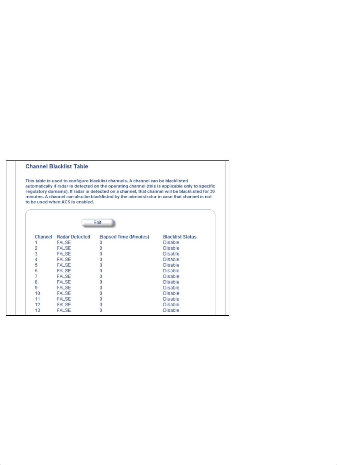
Configuration MeshMAX 5054 Series User Guide
Advanced Configuration of Mesh and Access Point Module
119
Frequency Selection/Radar Detection (DFS/RD) function. In the IC, FCC, ETSI, and TELEC regulatory domains, a
channel is blacklisted automatically if it is found to be busy or occupied by radar during a scan at start-up. When a
channel has been automatically blacklisted, it will remain blacklisted for 30 minutes. Additionally, an administrator can
blacklist channels manually to prevent them from being used when ACS is enabled.
NOTE: Any change in channel-related parameters (e.g., country code, turbo mode, Operational mode, H-band
operation) resets the channel blacklist table.
The channel blacklist table can be configured only through the Web or SNMP interfaces. CLI configuration is not
supported.
To blacklist a channel manually:
1. Click on Configure > Interfaces > Wireless A or Wireless B.
2. Scroll down to the Channel Blacklist heading.
Figure 6-12 Channel Blacklist Table
3. Click Edit in the Channel Blacklist Table
4. Set Blacklist Status to Enable.
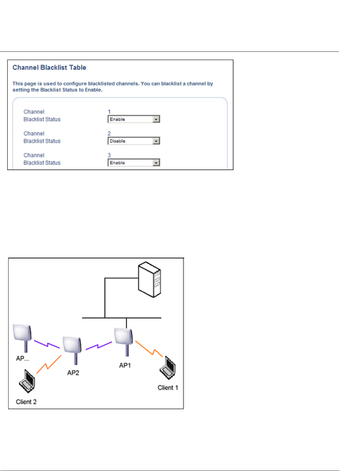
Configuration MeshMAX 5054 Series User Guide
Advanced Configuration of Mesh and Access Point Module
120
Figure 6-13 Channel Blacklist Table - Edit Screen
Wireless Distribution System (WDS)
A Wireless Distribution System (WDS) creates a link between two 4.9 GHz, 802.11a, 802.11b, or 802.11b/g APs over
their radio interfaces. This link relays traffic from one AP that does not have Ethernet connectivity to a second AP that has
Ethernet connectivity. WDS allows you to configure up to six (6) ports per radio (up to 12 ports in all).
In the WDS example below, AP 1 and AP 2 communicate over a WDS link (represented by the blue line). This link
provides Client 2 with access to network resources even though AP 2 is not directly connected to the Ethernet network.
Packets destined for or sent by the client are relayed between the Access Points over the WDS link.
Figure 6-14 WDS Example
Bridging WDS
Each WDS link is mapped to a logical WDS port on the AP. WDS ports behave like Ethernet ports rather than like
standard wireless interfaces: on a BSS port, an Access Point learns by association and from frames; on a WDS or
Ethernet port, an Access Point learns from frames only. When setting up a WDS, keep in mind the following:
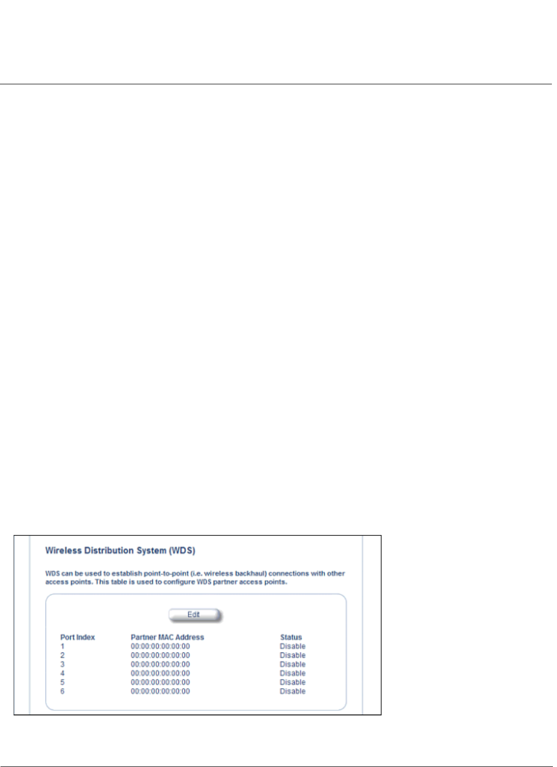
Configuration MeshMAX 5054 Series User Guide
Advanced Configuration of Mesh and Access Point Module
121
• WDS and Mesh functionality cannot be enabled on the same radio when the AP is configured to function as a Mesh
AP.
• There are separate security settings for clients and WDS links. The same WDS link security mode must be configured
(currently we only support none or WEP) on each Access Point in the WDS and the same WEP key must be
configured.
• The WDS link shares the communication bandwidth with the clients. Therefore, while the maximum data rate for the
Access Point's cell is 54 Mbits/second (802.11a, 4.9 GHz, 802.11g only, or 802.b/g modes) or 11 Mbits/second
(802.11b only mode), client throughput will decrease when traffic is passing over the WDS link.
• If there is no partner MAC address configured in the WDS table, the WDS port remains disabled.
• A WDS port on a single AP should have a unique partner MAC address. Do not enter the same MAC address twice in
an AP’s WDS port list.
• Each Access Point that is a member of the WDS must have the same Channel setting to communicate with each
other.
• If your network does not support spanning tree, be careful to avoid creating network loops between APs. For example,
creating a WDS link between two Access Points connected to the same Ethernet network will create a network loop (if
spanning tree is disabled). For more information, see the Spanning Tree section.
• When WDS is enabled, Spanning Tree protocol is automatically enabled. It may be manually disabled. If Spanning
Tree protocol is enabled by WDS and WDS is subsequently disabled, Spanning tree will remain enabled until it is
manually disabled. See Spanning Tree.
WDS Setup Procedure
NOTE: You must disable Auto Channel Select to create a WDS. Each Access Point that is a member of the WDS must
have the same channel setting to communicate with each other.
NOTE: WDS and Mesh functionality cannot be enabled on the same radio when the AP is configured to function as a
Mesh AP.
To setup a wireless backbone follow the steps below for each AP that you wish to include in the Wireless Distribution
System.
1. Confirm that Auto Channel Select is disabled.
2. Write down the MAC Address of the radio that you wish to include in the Wireless Distribution System.
3. Click on Configure > Interfaces > Wireless A or Wireless B.
4. Scroll down to the Wireless Distribution System heading.
Figure 6-15 WDS Configuration
Configuration MeshMAX 5054 Series User Guide
Advanced Configuration of Mesh and Access Point Module
122
5. Click the Edit button to update the Wireless Distribution System (WDS) Table.
Figure 6-16 Adding WDS Links
6. Select which encryption method to use (if any) from the WDS Security Mode drop-down menu.
7. If you selected a WDS Security Mode, do one of the following:
• If you selected WEP: Enter an encryption key.
• If you selected AES: Enter a shared secret.
8. Enter the MAC Address that you wrote down in Step 2 in one of the Partner MAC Address field of the Wireless
Distribution Setup window.
9. Set the Status of the device to Enable.
10.Click OK.
11.Reboot the AP.
Ethernet
Select the desired speed and transmission mode from the drop-down menu. Half-duplex means that only one side can
transmit at a time and full-duplex allows both sides to transmit. When set to auto-duplex, the AP negotiates with its switch
or hub to automatically select the highest throughput option supported by both sides.
Configuration MeshMAX 5054 Series User Guide
Advanced Configuration of Mesh and Access Point Module
123
Figure 6-17 Ethernet Sub-tab
For best results, Proxim recommends that you configure the Ethernet setting to match the speed and transmission mode
of the device the Access Point is connected to (such as a hub or switch). If in doubt, leave this setting at its default,
auto-speed-auto-duplex. Choose between:
• 10 Mbit/s - half duplex or full duplex
• 100 Mbit/s - half duplex or full duplex
• Auto speed - auto duplex
Mesh
Mesh functionality can be enabled on only one of the AP’s wireless interfaces. When configured for Mesh, the AP’s
wireless interface simultaneously functions as a Mesh link and as a radio to service clients.
CAUTION: Mesh mis-configuration may cause problems in your wireless network. Before configuring an interface for
Mesh functionality, see Mesh Network Configuration.
Configuration MeshMAX 5054 Series User Guide
Advanced Configuration of Mesh and Access Point Module
124
Basic Mesh Parameters
Figure 6-18 Basic Mesh Parameters
Configure the following basic parameters for Mesh functionality, and click OK.
NOTE: Changes to these parameters require a reboot in order to take effect.
•Mesh Mode: Use this drop down menu to enable/disable Mesh functionality on a wireless interface. When Mesh
Mode is set to Disable, all other parameters on this tab will be grayed out. To enable Mesh functionality, choose one of
the following:
–Mesh Portal: Choose this option if the AP will be connected directly to the wired backbone.
–Mesh AP: Choose this option if the AP will connect to the portal and backbone wirelessly.
NOTE: Proxim recommends enabling Auto Channel Select when configuring an AP as a Mesh AP. Auto Channel
Select is configured on the Wireless A or Wireless B page. See Wireless-A (802.11a or 4.9 GHz Radio)
and Wireless-B (802.11b/g Radio) for more information.
•Mesh Radio: Select the wireless interface on which to enable Mesh functionality. Select Wireless Interlace A (802.11a
radio or 4.9 GHz radio) or Wireless Interface B (802.11b/g radio).
•Mesh SSID: Enter a unique Mesh Network Name (SSID) between 1 and 16 characters.
NOTE: Do not use quotation marks (single or double) in the Network Name; this will cause the AP to misinterpret the
name.
•Security Mode: Select None to use Mesh networking without security, or AES to enable AES encryption between
Mesh links.
•Shared Secret: Enter a password between 6 and 32 characters. This is the password shared between a Mesh AP
and the Portal to which it is connected when AES is selected as the security mode.
Configuration MeshMAX 5054 Series User Guide
Advanced Configuration of Mesh and Access Point Module
125
•Mesh Mobility: Set this parameter to Fixed if the AP is statically placed, or to Mobile if the AP is mobile.
•QoS Policy Index: The index number of the QoS policy to be used by the Mesh radio. For more information on QoS,
see QoS.
•Disable Client Access on Mesh Radio: When this option is enabled, the AP will not accept clients on its Mesh radio.
When disabled, clients can link to the Mesh radio.
Advanced Mesh Parameters
Figure 6-19 Advanced Mesh Parameters
Click on the Advanced button on the Interfaces > Mesh page to access advanced Mesh parameters. The parameters
on the Advanced Mesh Parameters page are preconfigured with default settings that optimize the type of network
identified in the Mesh Mobility parameter on the previous page. Proxim recommends changing these values only if you
have advanced knowledge of Mesh networking.
Mesh Link Parameters
To reset these parameters to their default settings, click the Default button.
NOTE: Changes to these parameters require a reboot in order to take effect.
•Maximum Active Mesh Links: Select a number between 1 and 32 to configure the number of Mesh links that can be
connected to a single Mesh portal or Mesh AP, as follows:

Configuration MeshMAX 5054 Series User Guide
Advanced Configuration of Mesh and Access Point Module
126
–Mesh Portal: This number represents the maximum downlinks to Mesh APs (up to 32).
–Mesh AP: This number includes one mandatory uplink to the Mesh Portal, with the remaining links (up to 6)
available for downlinks to Mesh APs. A mobile Mesh AP should be configured to 1 to allow only uplinks.
– Proxim recommends a maximum of 30-40 APs total per portal (whether connected directly to the Portal or to
another Mesh AP). See Mesh Network Configuration.
•Maximum Hops to Portal: Set the maximum number of hops (1 to 4) allowed to reach the Mesh portal.
•Hop Factor: This parameter specifies how much weight should be given to the number of hops (vs. RSSI and
Medium Occupancy) when determining the best path to the Mesh Portal. The range is 0 to 10. Set the value to a
higher number to give more weight to this factor; set this value to a lower number to give less weight to this factor.
Setting this value to a lower number is beneficial in applications where an AP roams because of signal strength.
•RSSI Factor: This parameter specifies how much weight should be given to RSSI level (vs. number of hops and
Medium Occupancy) when determining the best path to the Mesh Portal. The range is 0 to 10. Set the value to a
higher number to give more weight to this factor; set this value to a lower number to give less weight to this factor.
•Medium Occupancy Factor: This parameter specifies how much weight should be given to Medium Occupancy level
(vs. number of hops and RSSI) when determining the best path to the Mesh Portal. The Medium Occupancy level is
the amount of wireless traffic on the channel. The range is 0 to 10. Set the value to a higher number to give more
weight to this factor; set this value to a lower number to give less weight to this factor.
•Receive Signal Strength Cut-Off: This parameter specifies the minimum level of received signal strength needed for
the node to be considered a Mesh link. If the Receive Signal Strength at the node is below this level, it is not
considered a link. Set this value to a number between 0 and 26 (dB).
•Roaming Threshold: The Roaming Threshold is the point at which the AP roams or chooses another link. The
threshold number is the difference between two path costs; if the difference is larger than the roaming threshold, the
AP roams; if the difference is smaller than the roaming threshold, the AP maintains its connection with the current link.
The range is 1 to 100. In a static Mesh environment, set this parameter to a high value to avoid switching links too
frequently. In a mobile Mesh environment, set this parameter to a lower value (1 - 20) to allow optimal link
establishment. Note that this parameter has no effect in Mesh Portal mode.
•User Defined Cost: This parameter allows the user to manually add cost to the overall path cost, in order to force
connection to one AP over another.
Auto Switch Mode Parameters
Auto Switch Mode parameters may be configured only for a Mesh Portal. Auto Switch mode allows an AP configured as
a Mesh Portal to switch its mode to be a Mesh AP if it loses its uplink (Ethernet) connection. If the uplink connection is
regained, the AP will switch back to Mesh Portal mode.
NOTE: Depending on the Ethernet connection, if Auto Switch Mode is enabled, the displayed Current Mesh Mode may
be different from the mode that was actually configured.
NOTE: Changes to these parameters require a reboot in order to take effect.
•Enable Auto Switch Mesh Mode: When enabled, an AP configured as a Mesh Portal can dynamically switch to
functioning as a Mesh AP if it loses its uplink connection.
NOTE: When enabling Auto Switch Mode, Proxim recommends that you also enable Auto Channel Select. ACS is
configured on the Wireless A or Wireless B page. See Wireless-A (802.11a or 4.9 GHz Radio) and
Wireless-B (802.11b/g Radio) for more information.
•Current Mesh Mode: Displays the current Mesh mode of the AP (Mesh Portal or Mesh AP).
•Disable Client Access on No Uplink Connection: When this option is enabled, the AP will not provide wireless
connections to clients on both radios if the unit does not have an uplink connection.
•Notify Clients on Uplink Change: When this option is enabled, the AP will send a deauthentication message to
currently connected clients when its uplink changes. This allows clients to restart a fresh connection, renewing their IP
addresses if necessary.
For more information on Mesh, see Mesh Networking.

Configuration MeshMAX 5054 Series User Guide
Advanced Configuration of Mesh and Access Point Module
127
Management
The Management tab contains the following sub-tabs:
•Passwords
•IP Access Table
•Services
•Automatic Configuration (AutoConfig)
•Hardware Configuration Reset (CHRD)
Passwords
Passwords are stored in flash memory and secured using encryption. You can configure the following passwords:
•SNMP Read Community Password: The password for read access to the AP using SNMP. Enter a password
between 6 and 32 characters in both the Password field and the Confirm field. The default password is public.
•SNMP Read/Write Community Password: The password for read and write access to the AP using SNMP. Enter a
password between 6 and 32 characters in both the Password field and the Confirm field. The default password is
public.
•SNMPv3 Authentication Password: The password used when sending authenticated SNMPv3 messages. Enter a
password in both the Password field and the Confirm field. This password must be between 6 and 32 characters, but
a length of at least 8 characters is recommended. The default password is public. Secure Management (Services tab)
must be enabled to configure SNMPv3.
The default SNMPv3 username is administrator, with SHA authentication and DES privacy protocol.
•SNMPv3 Privacy Password: The password used when sending encrypted SNMPv3 data. Enter a password in both
the Password field and the Confirm field. This password must be between 6 and 32 characters, but a length of at
least 8 characters is recommended. The default password is public. Secure Management (Services tab) must be
enabled to configure SNMPv3.
•Telnet (CLI) Password: The password for the CLI interface (via serial or Telnet). Enter a password between 6 and 32
characters in both the Password field and the Confirm field. The default password is public.
•HTTP (Web) Password: The password for the Web browser HTTP interface. Enter a password between 6 and 32
characters in both the Password field and the Confirm field. The default password is public.
NOTE: For security purposes Proxim recommends changing ALL PASSWORDS from the default “public” immediately, to
restrict access to your network devices to authorized personnel. If you lose or forget your password settings, you
can always perform a Soft Reset to Factory Defaults or Hard Reset to Factory Defaults.
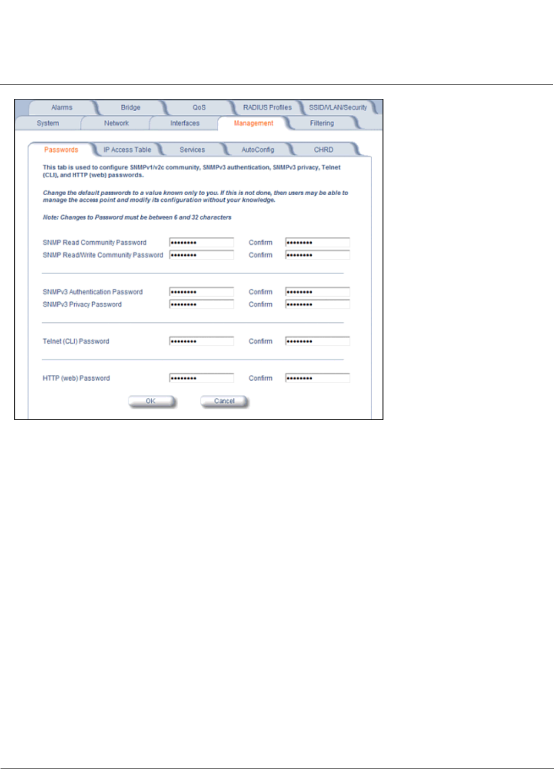
Configuration MeshMAX 5054 Series User Guide
Advanced Configuration of Mesh and Access Point Module
128
IP Access Table
The Management IP Access table limits in-band management access to the IP addresses or range of IP addresses
specified in the table. This feature applies to all management services (SNMP, HTTP, and CLI) except for CLI
management over the serial port. To configure this table, click Add and set the following parameters:
•IP Address: Enter the IP Address for the management station.
•IP Mask: Enter a mask that will act as a filter to limit access to a range of IP Addresses based on the IP Address you
already entered.
– The IP mask 255.255.255.255 would authorize the single station defined by the IP Address to configure the
Access Point. The AP would ignore commands from any other IP address. In contrast, the IP mask 255.255.255.0
would allow any device that shares the first three octets of the IP address to configure the AP. For example, if you
enter an IP address of 10.20.30.1 with a 255.255.255.0 subnet mask, any IP address between 10.20.30.1 and
10.20.30.254 will have access to the AP’s management interfaces.
•Comment: Enter an optional comment, such as the station name.
To edit or delete an entry, click Edit. Edit the information, or select Enable,Disable, or Delete from the Status pull-down
menu.
Services
You can configure the following management services:
Secure Management
Secure Management allows the use of encrypted and authenticated communication protocols such as SNMPv3, Secure
Socket Link (SSL), and Secure Shell (SSH) to manage the Access Point.

Configuration MeshMAX 5054 Series User Guide
Advanced Configuration of Mesh and Access Point Module
129
•Secure Management Status: Enables the further configuration of HTTPS Access, SNMPv3, and Secure Shell
(SSH). After enabling Secure Management, you can choose to configure HTTPS (SSL) and Secure Shell access on
the Services tab, and to configure SNMPv3 passwords on the Passwords tab.
SNMP Settings
•SNMP Interface Bitmask: Configure the interface or interfaces (Ethernet,Wireless-Slot A, Wireless-Slot B,All
Interfaces) from which you will manage the AP via SNMP. You can also select Disabled to prevent a user from
accessing the AP via SNMP.
HTTP Access
•HTTP Interface Bitmap: Configure the interface or interfaces (Ethernet,Wireless-Slot A, Wireless-Slot B,All
Interfaces) from which you will manage the AP via the Web interface. For example, to allow Web configuration via the
Ethernet network only, set HTTP Interface Bitmask to Ethernet. You can also select Disabled to prevent a user from
accessing the AP from the Web interface.
•HTTP Port: Configure the HTTP port from which you will manage the AP via the Web interface. By default, the HTTP
port is 80. You must reboot the Access Point if you change the HTTP Port.
•HTTP Wizard Status: The Setup Wizard appears automatically the first time you access the HTTP interface. If you
exited out of the Setup Wizard and want to relaunch it, enable this option, click OK, and then close your browser or
reboot the AP. The Setup Wizard will appear the next time you access the HTTP interface.
HTTPS Access (Secure Socket Layer)
NOTE: SSL requires Internet Explorer version 6, 128 bit encryption, Service Pack 1, and patch Q323308.
NOTE: You need to reboot the AP after enabling or disabling SSL for the changes to take effect.
•HTTPS (Secure Web Status): The user can access the AP in a secure fashion using Secure Socket Layer (SSL)
over port 443. The AP comes pre-installed with all required SSL files: default certificate and private key installed. Use
the drop-down menu to enable/disable this feature.
•SSL Certificate Passphrase: After enabling SSL, the only configurable parameter is the SSL passphrase. The
default SSL passphrase is proxim.
The AP supports SSLv3 with a 128-bit encryption certificate maintained by the AP for secure communications
between the AP and the HTTP client. All communications are encrypted using the server and the client-side
certificate.
If you decide to upload a new certificate and private key (using TFTP or HTTP File Transfer), you need to change the
SSL Certificate Passphrase for the new SSL files.
Accessing the AP through the HTTPS interface
The user should use a SSL intelligent browser to access the AP through the HTTPS interface. After configuring SSL,
access the AP using https:// followed by the AP’s management IP address.
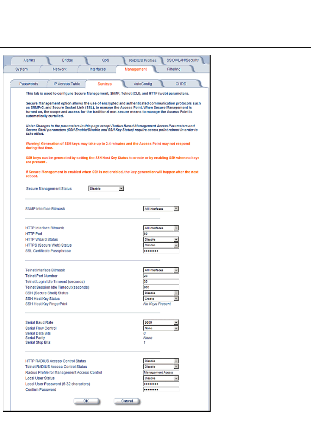
Configuration MeshMAX 5054 Series User Guide
Advanced Configuration of Mesh and Access Point Module
130
Figure 6-20 Management Services Configuration Screen

Configuration MeshMAX 5054 Series User Guide
Advanced Configuration of Mesh and Access Point Module
131
Telnet Configuration Settings
•Telnet Interface Bitmask: Select the interface (Ethernet,Wireless-Slot A, Wireless-Slot B,All Interfaces) from
which you can manage the AP via telnet. This parameter can also be used to Disable telnet management.
•Telnet Port Number: The default port number for Telnet applications is 23. However, you can use this field if you want
to change the Telnet port for security reasons (but your Telnet application also must support the new port number you
select). You must reboot the Access Point if you change the Telnet Port.
•Telnet Login Idle Timeout (seconds): Enter the number of seconds the system will wait for a login attempt. The AP
terminates the session when it times out. The range is 30 to 300 seconds; the default is 60 seconds.
•Telnet Session Idle Timeout (seconds): Enter the number of seconds the system will wait during a session while
there is no activity. The AP will terminate the session on timeout. The range is 60 to 36000 seconds; the default is 900
seconds.
Secure Shell (SSH) Settings
The AP supports SSH version 2, for secure remote CLI (Telnet) sessions. SSH provides strong authentication and
encryption of session data.
The SSH server (AP) has host keys - a pair of asymmetric keys - a private key that resides on the AP and a public key
that is distributed to clients that need to connect to the AP. As the client has knowledge of the server host keys, the client
can verify that it is communicating with the correct SSH server. The client authentication is performed as follows:
• Using a username/password pair if RADIUS Based Management is enabled; otherwise, using a password to
authenticate the user over a secure channel created using SSH.
SSH Session Setup
An SSH session is setup through the following process:
• The SSH server public key is transferred to the client using out-of-band or in-band mechanisms.
• The SSH client verifies the correctness of the server using the server’s public key.
• The user/client authenticates to the server.
• An encrypted data session starts. The maximum number of SSH sessions is limited to two. If there is no activity for a
specified amount of time (the Telnet Session Timeout parameter), the AP will timeout the connection.
SSH Clients
The following SSH clients have been verified to interoperate with the AP’s server. The following table lists the clients,
version number, and the website of the client.
For key generation, OpenSSH client has been verified.
Configuring SSH
Perform the following procedure to set the SSH host key and enable or disable SSH:
1. Click Configure > Management > Services
2. Select the SSH Host Key Status from the drop down menu.
NOTE: SSH Host Key Status can not be changed if SSH status or Secure Management is enabled.
3. To enable/disable SSH, select Enable/Disable from the SSH (Secure Shell) Status drop-down menu.
Clients Version Website
OpenSSH V3.4-2 http://www.openssh.com
Putty Rel 0.53b http://www.chiark.greenend.org.uk
Zoc 5.00 http://www.emtec.com
Axessh V2.5 http://www.labf.com
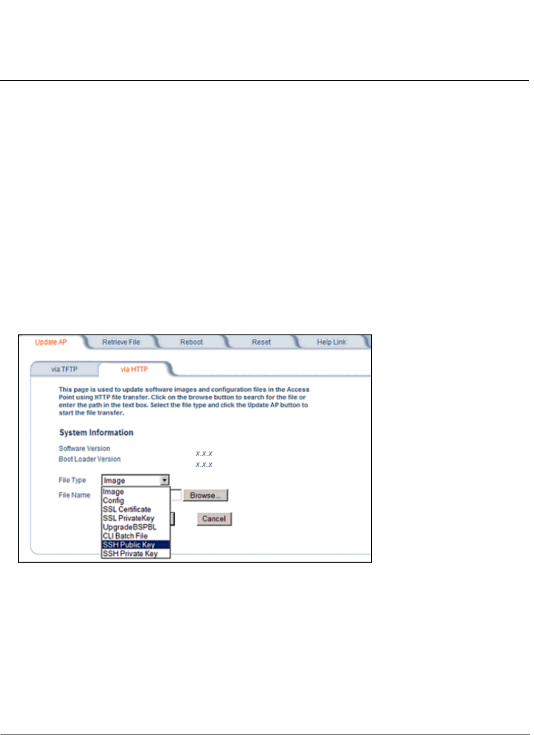
Configuration MeshMAX 5054 Series User Guide
Advanced Configuration of Mesh and Access Point Module
132
NOTE: When Secure Management is enabled on the AP, SSH will be enabled by default and cannot be disabled.
Host keys must either be generated externally and uploaded to the AP (see Uploading Externally Generated Host Keys),
generated manually, or auto-generated at the time of SSH initialization if SSH is enabled and no host keys are present.
There is no key present in an AP that is in a factory default state.
To manually generate or delete host keys on the AP:
CAUTION: SSH Host key creation may take 3 to 4 minutes during which time the AP may not respond.
•Select Create to generate a new pair of host keys.
•Select Delete to remove the host keys from the AP. If no host keys are present, the AP will not allows connections
using SSH. When host keys are created or deleted, the AP updates the fingerprint information displayed on the
Management > Services page.
Uploading Externally Generated Host Keys
Perform the following procedure to upload externally generated host keys to the AP. You must upload both the SSH
public key and SSH private key for SSH to work.
1. Verify that the host keys have been externally generated. The OpenSSH client has been verified to interoperate with
AP’s SSH server.
2. Click Commands > Update AP > via HTTP (or via TFTP).
Figure 6-21 Uploading an Externally Generated SSH Public Key and SSH Private Key
3. Select SSH Public Key from the File Type drop-down menu.
4. Click Browse, select the SSH Public Key file on your local machine.
5. Click Open.
6. to initiate the file transfer, click the Update AP button.
7. Select SSH Private Key from the File Type drop-down menu.
8. Click Browse, select the SSH Private Key on your local machine.
9. Click Open.
10.To initiate the file transfer, click the Update AP button.
The fingerprint of the new SSH public key will be displayed in the Management > Services page.

Configuration MeshMAX 5054 Series User Guide
Advanced Configuration of Mesh and Access Point Module
133
Serial Configuration Settings
The serial port interface on the AP is enabled at all times. See Setting IP Address using Serial Port for information on how
to access the CLI interface via the serial port. You can configure and view the following parameters:
•Serial Baud Rate: Select the serial port speed (bits per second). Choose between 2400, 4800, 9600, 19200, 38400,
or 57600; the default Baud Rate is 9600.
•Serial Flow Control: Select either None (default) or Xon/Xoff (software controlled) data flow control.
NOTE: To avoid potential problems when communicating with the AP through the serial port, Proxim recommends
that you leave the Flow Control setting at None (the default value).
•Serial Data Bits: This is a read-only field and displays the number of data bits used in serial communication (8 data
bits by default).
•Serial Parity: This is a read-only field and displays the number of parity bits used in serial communication (no parity
bits by default).
•Serial Stop Bits: This is a read-only field that displays the number of stop bits used in serial communication (1 stop
bit by default).
NOTE: The serial port bit configuration is commonly referred to as 8N1.
RADIUS Based Management Access
User management of APs can be centralized by using a RADIUS server to store user credentials. The AP cross-checks
credentials using RADIUS protocol and the RADIUS server accepts or rejects the user.
HTTP/HTTPS and Telnet/SSH users can be managed with RADIUS. Serial CLI and SNMP cannot be managed by
RADIUS. Two types of users can be supported using centralized RADIUS management:
•Super User: The super user has access to all functionality of a management interface. A super user is configured in
the RADIUS server by setting the filter ID attribute (returned in the RADIUS Accept packet) for the user to a value of
“super user” (not case sensitive). A user is considered a super user if the value of the filter-id attribute returned in the
RADIUS Accept packet for the user is “super user” (not case sensitive).
•Limited User: A limited user has access to only a limited set of functionality on a management interface. All users
who are not super users are considered limited users. However, a limited user is configured in the RADIUS server by
setting the filter-id attribute (returned in the RADIUS Accept packet) to “limited user” (not case sensitive). Limited
users do not have access to the following configuration capabilities:
– Update/retrieve files to and from APs
– Reset the AP to factory defaults
– Reboot the AP
– Change management properties related to RADIUS, management modes, and management passwords.
NOTE: When a user has both “limited user” and “super user” filter-ids configured in the Radius server, the user has
limited user privileges.
When RADIUS Based Management is enabled, a local user can be configured to provide Telnet, SSH, and HTTP(S)
access to the AP when RADIUS servers fail. The local user has super user capabilities. When secure management is
enabled, the local user can only login using secure means (i.e., SSH or SSL). When the local user option is disabled the
only access to the AP when RADIUS servers are down will be through serial CLI or SNMP.
The Radius Based Management Access parameters allows you to enable HTTP or Telnet Radius Management Access,
to configure a RADIUS Profile for management access control, and to enable or disable local user access, and configure
the local user password. You can configure and view the following parameters:
•HTTP RADIUS Access Control Status: Enable RADIUS management of HTTP/HTTPS users.
•Telnet RADIUS Access Control Status: Enable RADIUS management of Telnet/SSH users.

Configuration MeshMAX 5054 Series User Guide
Advanced Configuration of Mesh and Access Point Module
134
•RADIUS Profile for Management Access Control: Specifies the RADIUS Profile to be used for RADIUS Based
Management Access.
•Local User Status: Enables or disables the local user when RADIUS Based Management is enabled. The default
local user ID is root.
•Local User Password and Confirm Password: The default local user password is public. “Root” cannot be
configured as a valid user for Radius based management access when local user access is enabled.
Automatic Configuration (AutoConfig)
The Automatic Configuration feature which allows an AP to be automatically configured by downloading a specific
configuration file from a TFTP server during the boot up process.
Automatic Configuration is disabled by default. The configuration process for Automatic Configuration varies depending
on whether the AP is configured for dynamic or static IP.
When an AP is configured for dynamic IP, the Configuration filename and the TFTP server IP address are contained in
the DHCP response when the AP gets its IP address dynamically from the DHCP server. When configured for static IP,
these parameters are instead configured in the AP interface.
After setting up automatic configuration you must reboot the AP. When the AP reboots it receives the new configuration
information and must reboot one additional time. If Syslog is configured, a Syslog message will appear indicating the
success or failure of the Automatic Configuration.
Auto Configuration and the CLI Batch File
The Auto Configuration feature allows download of the LTV (Length, Type, Value) format configuration file or the CLI
Batch file. The LTV file contains parameters used by the AP; the CLI Batch file contains CLI executable commands used
to set AP parameters. The AP detects whether the uploaded file is LTV format or a CLI Batch file. If the AP detects an
LTV file, it stores the file in the AP’s flash memory. If the AP detects a CLI Batch file (a file with an extension of .cli), the
AP executes the commands contained in the file immediately. The AP will reboot after executing the CLI Batch file. Auto
Configuration will not result in repeated reboots if the CLI Batch file contains rebootable parameters.
For more information, see the CLI Batch File section.
Set up Automatic Configuration for Static IP
Perform the following procedure to enable and set up Automatic Configuration when you have a static IP address for the
TFTP server.
1. Click Configure > Management > AutoConfig. The Automatic Configuration Screen appears.
2. Check Enable Auto Configuration.
3. Enter the Configuration Filename. The default is config.
4. Enter the IP address of the TFTP server in the TFTP Server Address field. The default is 169.254.128.133.
NOTE: The default filename is “config”. The default TFTP IP address is 169.254.128.133.
5. Click OK to save the changes.
6. Reboot the AP. When the AP reboots it receives the new configuration information and must reboot one additional
time. If a Syslog server was configured, the following messages can be observed on the Syslog server:
• AutoConfig for Static IP
• TFTP server address and configuration filename
• AutoConfig Successful
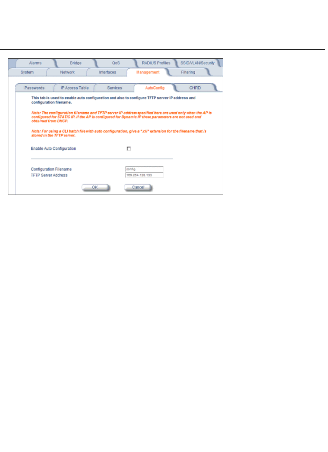
Configuration MeshMAX 5054 Series User Guide
Advanced Configuration of Mesh and Access Point Module
135
Figure 6-22 Automatic Configuration Screen
Set up Automatic Configuration for Dynamic IP
Perform the following procedure to enable and set up Automatic Configuration when you have a dynamic IP address for
the TFTP server via DHCP.
The Configuration filename and the TFTP server IP address are contained in the DHCP response when the AP gets its IP
address dynamically from the DHCP server. A Syslog server address is also contained in the DHCP response, allowing
the AP to send Auto Configuration success and failure messages to a Syslog server.
NOTE: The configuration filename and TFTP server IP address are configured only when the AP is configured for Static
IP. If the AP is configured for Dynamic IP these parameters are not used and obtained from DHCP.
1. Click Configure > Management > AutoConfig.
The Automatic Configuration screen appears.
2. Check Enable Auto Configuration.
When the AP is Configured with Dynamic IP, the DHCP server should be configured with the TFTP Server IP address
("Boot Server Host Name", option 66) and Configuration file ("Bootfile name", option 67) as follows (note that this
example uses a Windows 2000 server):
3. Select DHCP Server > DHCP Option > Scope.
The DHCP Options: Scope screen appears.
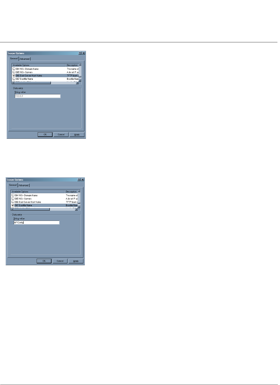
Configuration MeshMAX 5054 Series User Guide
Advanced Configuration of Mesh and Access Point Module
136
Figure 6-23 DHCP Options: Setting the Boot Server Host Name
4. Add the Boot Server Hostname and Boot Filename parameters to the Available Options list.
5. Set the value of the Boot Server Hostname Parameter to the hostname or IP Address of the TFTP server. For
example: 11.0.0.7.
Figure 6-24 DHCP Options: Setting the Bootfile Name
6. Set the value of the Bootfile Name parameter to the Configuration filename. For example: AP-Config.
7. If using Syslog, set the Log server IP address (option 7, Log Servers).
8. Reboot the AP. When the AP reboots it receives the new configuration information and must reboot one additional
time. If a Syslog server was configured, the following messages can be observed on the Syslog server:
• AutoConfig for Dynamic IP
• TFTP server address and configuration filename
• AutoConfig Successful
Hardware Configuration Reset (CHRD)
Hardware Configuration Reset Status is a parameter that defines the hardware configuration reset behavior of the AP.
If a user loses or forgets the AP’s HTTP/Telnet/SNMP password, the Reload button on the power injector provides a way
to reset the AP to default configuration values and gain access to the AP. However, in AP deployments where physical
access to the AP is not protected, an unauthorized person could reset the AP to factory defaults and thus gain control of
the AP. The user can disable the hardware configuration reset functionality to prevent unauthorized access.
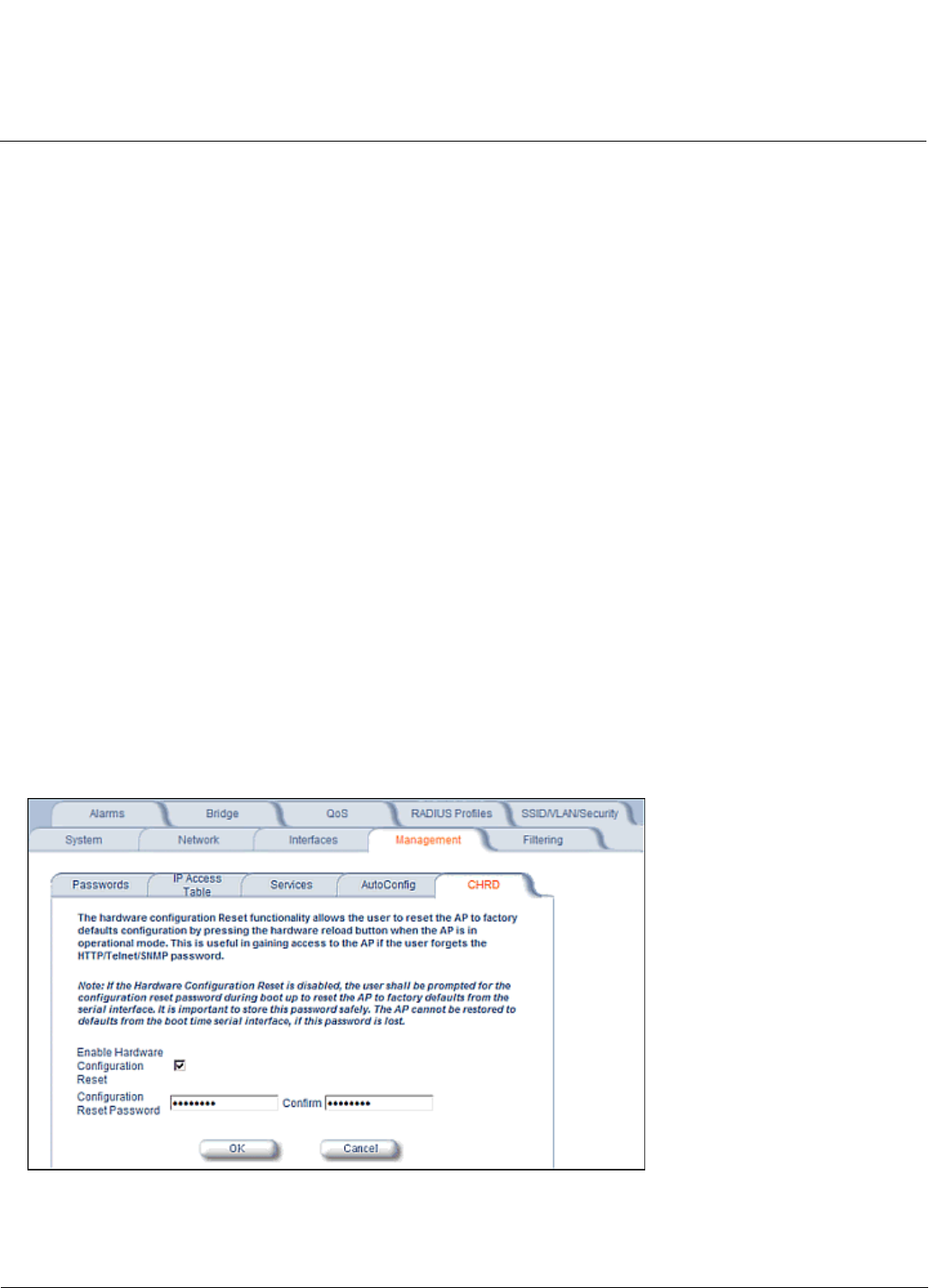
Configuration MeshMAX 5054 Series User Guide
Advanced Configuration of Mesh and Access Point Module
137
The hardware configuration reset feature operates as follows:
• When hardware configuration reset is enabled, the user can press the Reload button on the power injector for 10
seconds when the AP is in normal operational mode in order to delete the AP configuration.
• When hardware configuration reset is disabled, pressing the Reload button when the AP is in normal operational
mode does not have any effect on the AP.
• The hardware configuration reset parameter does not have any effect on the functionality of the reload button to
delete the AP image during AP boot loader execution.
• The default hardware configuration reset status is enabled. When disabling hardware configuration reset, the user is
recommended to configure a configuration reset password. A configuration reset option appears on the serial port
during boot up, before the AP reads its configuration and initializes.
• Whenever the AP is reset to factory default configuration, hardware configuration reset status is enabled and the
configuration reset password is set to the default, “public”.
• If secure mode is enabled in the AP, only secure (SSL, SNMPv3, SSH) users can modify the values of the Hardware
Configuration Reset Status and the configuration reset password.
Configuration Reset via Serial Port During Bootup
If hardware configuration reset is disabled, the user gets prompted by a configuration reset option to reset the AP to
factory defaults during boot up from the serial interface. By pressing a key sequence (ctrl-R), the user gets prompted to
enter a configuration reset password before the configuration is reset.
NOTE: It is important to safely store the configuration reset password. If a user forgets the configuration reset password,
the user will be unable to reset the AP to factory default configuration if the AP becomes inaccessible and the
hardware configuration reset functionality is disable.
Configuring Hardware Configuration Reset
Perform the following procedure to configure Hardware Configuration Reset and to set the Configuration Reset
Password. See Figure 6-25.
1. Click Configure > Management > CHRD.
Figure 6-25 Hardware Configuration Reset
2. Check (enable) or uncheck (disable) the Enable Hardware Configuration Reset checkbox.
3. Change the default Configuration Reset Password in the “Configuration Reset Password” and “Confirm” fields.

Configuration MeshMAX 5054 Series User Guide
Advanced Configuration of Mesh and Access Point Module
138
4. Click OK.
5. Reboot the AP.
NOTE: It is important to safely store the configuration reset password. If a user forgets the configuration reset password,
the user will be unable to reset the AP to factory default configuration if the AP becomes inaccessible and the
hardware configuration reset functionality is disable.
Procedure to Reset Configuration via the Serial Interface
1. During boot up, observe the message output on the serial interface.
The AP prompts the user with the message: “Press ctrl-R in 3 seconds to choose configuration reset option.”
2. Enter ctrl-R within 3 seconds after being prompted.
The AP prompts the user with “Press ctrl-Z to continue with normal boot up or enter password to reset configuration.”
If the user enters ctrl-Z, the AP continues to boot with the stored configuration.
3. Enter the configuration reset password. The default configuration reset password is “public”.
When the correct configuration reset password is entered, the AP gets reset to factory defaults and displays the
message “AP has been reset to Factory Default Settings.” The AP continues to boot up. If an incorrect configuration
reset password is entered, the AP shows an error message and reprompts the user. If the incorrect password is
entered three times in a row, the AP proceeds to boot up.
Filtering
The Access Point’s Packet Filtering features help control the amount of traffic exchanged between the wired and wireless
networks. There are four sub-tabs under the Filtering heading:
•Ethernet Protocol
•Static MAC
•Advanced
•TCP/UDP Port
Ethernet Protocol
The Ethernet Protocol Filter blocks or forwards packets based on the Ethernet protocols they support.
Follow these steps to configure the Ethernet Protocol Filter:
1. Select the interface or interfaces that will implement the filter from the Ethernet Protocol Filtering drop-down menu.
•Ethernet: Packets are examined at the Ethernet interface
•Wireless-Slot A or Wireless-Slot B: Packets are examined at the Wireless A or B interfaces
•All Interfaces: Packets are examined at both interfaces
•Disabled: The filter is not used
2. Select the Filter Operation Type.
• If set to Passthru, only the enabled Ethernet Protocols listed in the Filter Table will pass through the bridge.
• If set to Block, the bridge will block enabled Ethernet Protocols listed in the Filter Table.
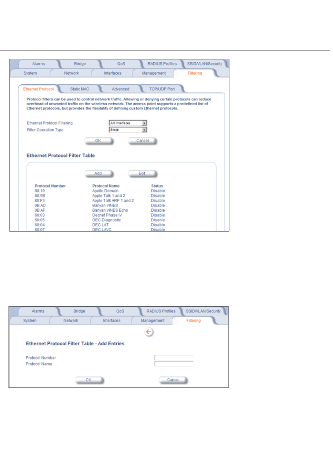
Configuration MeshMAX 5054 Series User Guide
Advanced Configuration of Mesh and Access Point Module
139
Figure 6-26 Ethernet Protocol Filter Configuration
3. Configure the Ethernet Protocol Filter Table. This table is pre-populated with existing Ethernet Protocol Filters,
however, you may enter additional filters by specifying the appropriate parameters.
• To add an entry, click Add, and then specify the Protocol Number and a Protocol Name.
–Protocol Number: Enter the protocol number. See http://www.iana.org/assignments/ethernet-numbers for a
list of protocol numbers.
–Protocol Name: Enter related information, typically the protocol name.
Figure 6-27 Ethernet Protocol Filter Table - Add Entries
• To edit or delete an entry, click Edit and change the information, or select Enable,Disable, or Delete from the
Status drop-down menu.
NOTE: An entry’s status must be enabled in order for the protocol to be subject to the filter.
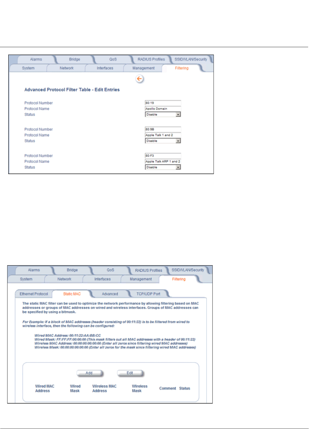
Configuration MeshMAX 5054 Series User Guide
Advanced Configuration of Mesh and Access Point Module
140
Figure 6-28 Ethernet Protocol Filter Table - Edit Entries
Static MAC
The Static MAC Address filter optimizes the performance of a wireless (and wired) network. When this feature is properly
configured, the AP can block traffic between wired devices and wireless devices based on MAC address.
For example, you can set up a Static MAC filter to prevent wireless clients from communicating with a specific server on
the Ethernet network. You can also use this filter to block unnecessary multicast packets from being forwarded to the
wireless network.
NOTE: The Static MAC Filter is an advanced feature. You may find it easier to control wireless traffic via other filtering
options, such as Ethernet Protocol Filtering.
Figure 6-29 Static MAC Filter Configuration
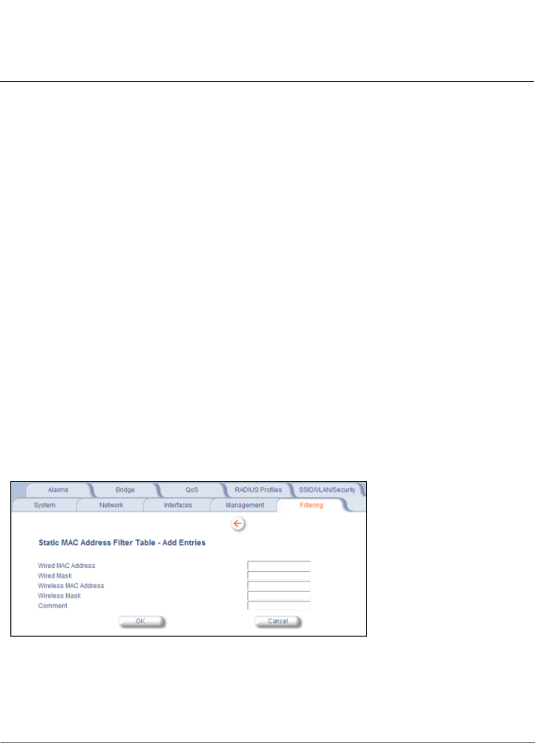
Configuration MeshMAX 5054 Series User Guide
Advanced Configuration of Mesh and Access Point Module
141
Each static MAC entry contains the following fields:
•Wired MAC Address
•Wired Mask
•Wireless MAC Address
•Wireless Mask
•Comment: This field is optional.
Each MAC Address or Mask is comprised of 12 hexadecimal digits (0-9, A-F) that correspond to a 48-bit identifier. (Each
hexadecimal digit represents 4 bits (0 or 1).)
Taken together, a MAC Address/Mask pair specifies an address or a range of MAC addresses that the AP will look for
when examining packets. The AP uses Boolean logic to perform an “AND” operation between the MAC Address and the
Mask at the bit level. However, for most users, you do not need to think in terms of bits. It should be sufficient to create a
filter using only the hexadecimal digits 0 and F in the Mask (where 0 is any value and F is the value specified in the MAC
address). A Mask of 00:00:00:00:00:00 corresponds to all MAC addresses, and a Mask of FF:FF:FF:FF:FF:FF applies
only to the specified MAC Address.
For example, if the MAC Address is 00:20:A6:12:54:C3 and the Mask is FF:FF:FF:00:00:00, the AP will examine the
source and destination addresses of each packet looking for any MAC address starting with 00:20:A6. If the Mask is
FF:FF:FF:FF:FF:FF, the AP will only look for the specific MAC address (in this case, 00:20:A6:12:54:C3).
When creating a filter, you can configure the Wired parameters only, the Wireless parameters only, or both sets of
parameters. Which parameters to configure depends upon the traffic that you want block:
• To prevent all traffic from a specific wired MAC address from being forwarded to the wireless network, configure only
the Wired MAC Address and Wired Mask (leave the Wireless MAC Address and Wireless Mask set to all zeros).
• To prevent all traffic from a specific wireless MAC address from being forwarded to the wired network, configure only
the Wireless MAC address and Wireless Mask (leave the Wired MAC Address and Wired Mask set to all zeros).
• To block traffic between a specific wired MAC address and a specific wireless MAC address, configure all four
parameters.
A maximum of 200 entries can be created in the Static MAC filter table. To create an entry, click Add and enter the
appropriate MAC addresses and Masks to setup a filter. The entry is enabled automatically when saved.
Figure 6-30 Static MAC Filter Table - Add Entries
To edit an entry, click Edit. To disable or remove an entry, click Edit and change the Status field from Enable to Disable
or Delete.

Configuration MeshMAX 5054 Series User Guide
Advanced Configuration of Mesh and Access Point Module
142
Static MAC Filter Examples
Consider a network that contains a wired server and three wireless clients. The MAC address for each unit is as follows:
• Wired Server: 00:40:F4:1C:DB:6A
• Wireless Client 1: 00:02:2D:51:94:E4
• Wireless Client 2: 00:02:2D:51:32:12
• Wireless Client 3: 00:20:A6:12:4E:38
Prevent Two Specific Devices from Communicating
Configure the following settings to prevent the Wired Server and Wireless Client 1 from communicating:
•Wired MAC Address: 00:40:F4:1C:DB:6A
•Wired Mask: FF:FF:FF:FF:FF:FF
•Wireless MAC Address: 00:02:2D:51:94:E4
•Wireless Mask: FF:FF:FF:FF:FF:FF
Result: Traffic between the Wired Server and Wireless Client 1 is blocked. Wireless Clients 2 and 3 can still communicate
with the Wired Server.
Prevent Multiple Wireless Devices from Communicating with a Single Wired Device
Configure the following settings to prevent Wireless Clients 1 and 2 from communicating with the Wired Server:
•Wired MAC Address: 00:40:F4:1C:DB:6A
•Wired Mask: FF:FF:FF:FF:FF:FF
•Wireless MAC Address: 00:02:2D:51:94:E4
•Wireless Mask: FF:FF:FF:00:00:00
Result: When a logical “AND” is performed on the Wireless MAC Address and Wireless Mask, the result corresponds to
any MAC address beginning with the 00:20:2D prefix. Since Wireless Client 1 and Wireless Client 2 share the same
prefix (00:02:2D), traffic between the Wired Server and Wireless Clients 1 and 2 is blocked. Wireless Client 3 can still
communicate with the Wired Server since it has a different prefix (00:20:A6).
Prevent All Wireless Devices from Communicating with a Single Wired Device
Configure the following settings to prevent all three Wireless Clients from communicating with Wired Server 1:
•Wired MAC Address: 00:40:F4:1C:DB:6A
•Wired Mask: FF:FF:FF:FF:FF:FF
•Wireless MAC Address: 00:00:00:00:00:00
•Wireless Mask: 00:00:00:00:00:00
Result: The Access Point blocks all traffic between Wired Server 1 and all wireless clients.
Prevent a Wireless Device from Communicating with the Wired Network
Configure the following settings to prevent Wireless Client 3 from communicating with any device on the Ethernet:
•Wired MAC Address: 00:00:00:00:00:00
•Wired Mask: 00:00:00:00:00:00
•Wireless MAC Address: 00:20:A6:12:4E:38
•Wireless Mask: FF:FF:FF:FF:FF:FF
Result: The Access Point blocks all traffic between Wireless Client 3 and the Ethernet network.

Configuration MeshMAX 5054 Series User Guide
Advanced Configuration of Mesh and Access Point Module
143
Prevent Messages Destined for a Specific Multicast Group from Being Forwarded to the Wireless LAN
If there are devices on your Ethernet network that use multicast packets to communicate and these packets are not
required by your wireless clients, you can set up a Static MAC filter to preserve wireless bandwidth. For example, if
routers on your network use a specific multicast address (such as 01:00:5E:00:32:4B) to exchange information, you can
set up a filter to prevent these multicast packets from being forwarded to the wireless network:
•Wired MAC Address: 01:00:5E:00:32:4B
•Wired Mask: FF:FF:FF:FF:FF:FF
•Wireless MAC Address: 00:00:00:00:00:00
•Wireless Mask: 00:00:00:00:00:00
Result: The Access Point does not forward any packets that have a destination address of 01:00:5E:00:32:4B to the
wireless network.
Advanced
You can configure the following advanced filtering options:
•Enable Proxy ARP: Place a check mark in the box provided to allow the Access Point to respond to Address
Resolution Protocol (ARP) requests for wireless clients. When enabled, the AP answers ARP requests for wireless
stations without actually forwarding them to the wireless network. If disabled, the Access Point will bridge ARP
requests for wireless clients to the wireless LAN.
•Enable IP/ARP Filtering: Place a check mark in the box provided to allow IP/ARP filtering based on the IP/ARP
Filtering Address and IP Mask. Leave the box unchecked to prevent filtering. If enabled, you should also configure the
IP/ARP Filtering Address and IP/ARP IP Mask.
–IP/ARP Filtering Address: Enter the Network filtering IP Address.
–IP/ARP IP Mask: Enter the Network Mask IP Address.
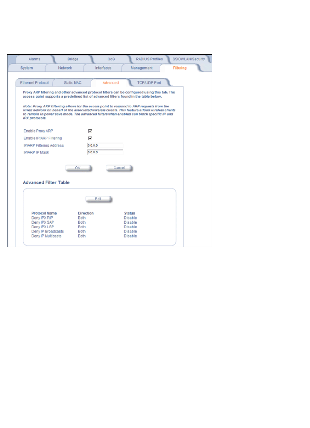
Configuration MeshMAX 5054 Series User Guide
Advanced Configuration of Mesh and Access Point Module
144
Figure 6-31 Advanced Filter Configuration
The following protocols are listed in the Advanced Filter Table:
•Deny IPX RIP
•Deny IPX SAP
•Deny IPX LSP
•Deny IP Broadcasts
•Deny IP Multicasts
The AP can filter these protocols in the wireless-to-Ethernet direction, the Ethernet-to-wireless direction, or in both
directions. Click Edit and use the Status field to Enable or Disable the filter.
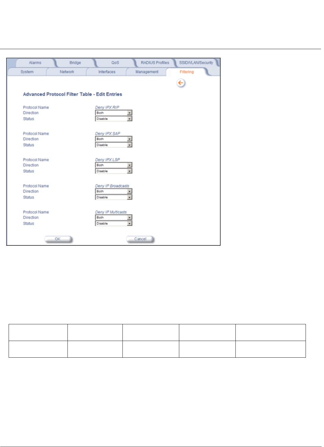
Configuration MeshMAX 5054 Series User Guide
Advanced Configuration of Mesh and Access Point Module
145
Figure 6-32 Static MAC Filter Table - Edit Entries
TCP/UDP Port
Port-based filtering enables you to control wireless user access to network services by selectively blocking TCP/UDP
protocols through the AP. A user specifies a Protocol Name, Port Number, Port Type (TCP, UDP, or TCP/UDP), and
filtering interfaces (Wireless radio A or B only, Ethernet only, a combination of Wireless radio A or B and Ethernet, or all
interfaces) in order to block access to services, such as Telnet and FTP, and traffic, such as NETBIOS and HTTP.
For example, an AP with the following configuration would discard frames received on its Ethernet interface with a UDP
destination port number of 137, effectively blocking NETBIOS Name Service packets.
Adding TCP/UDP Port Filters
1. Place a check mark in the box labeled Enable TCP/UDP Port Filtering.
Protocol Type
(TCP/UDP)
Destination Port
Number
Protocol Name Interface Status (Enable/Disable)
UDP 137 NETBIOS Name
Service
Ethernet Enable
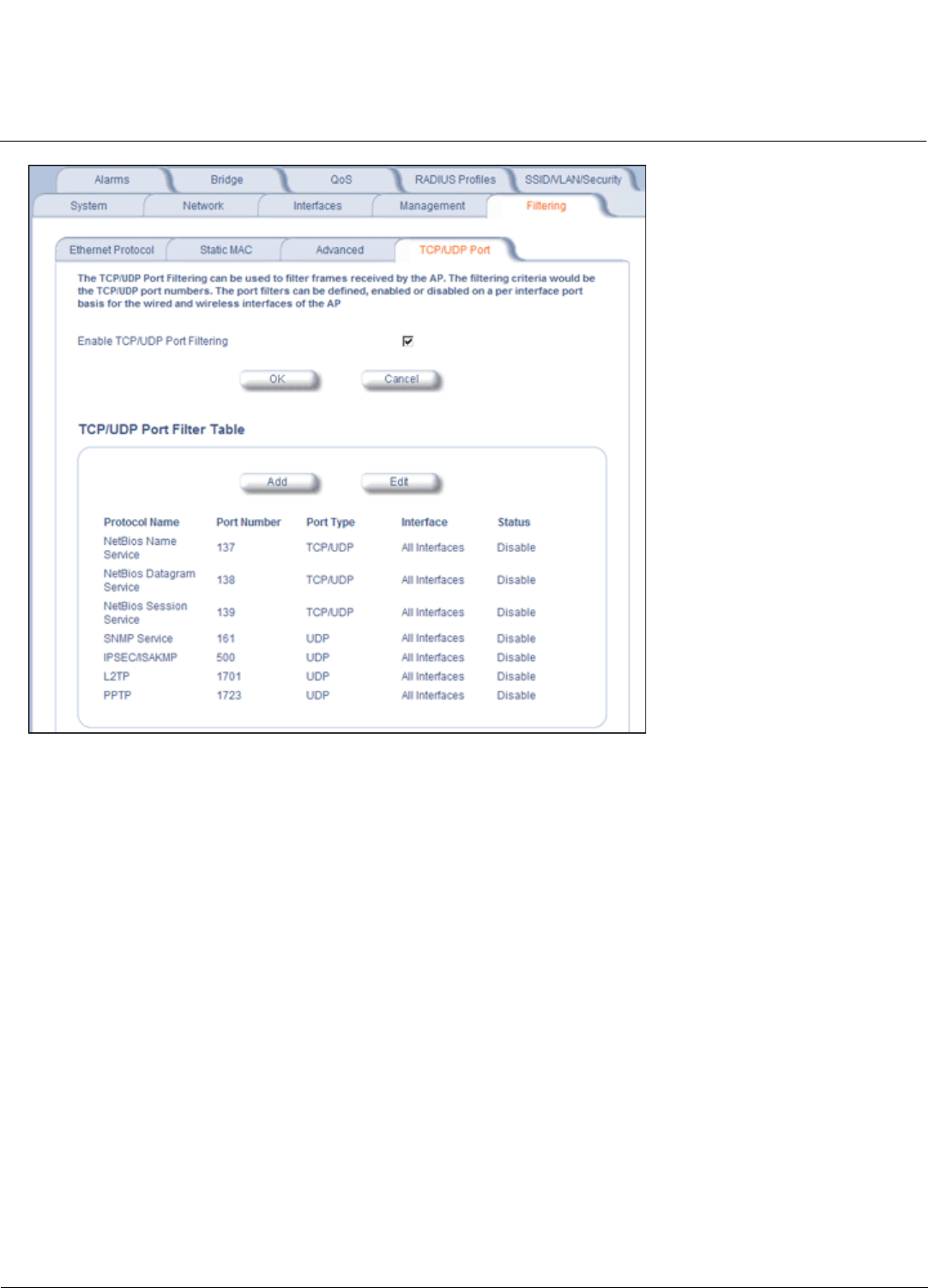
Configuration MeshMAX 5054 Series User Guide
Advanced Configuration of Mesh and Access Point Module
146
Figure 6-33 TCP/UDP Port Filter Configuration
2. Click Add under the TCP/UDP Port Filter Table heading.
3. In the TCP/UDP Port Filter Table, enter the Protocol Names to filter.
4. Set the destination Port Number (a value between 1 and 65535) to filter. See the IANA Web site at
http://www.iana.org/assignments/port-numbers for a list of assigned port numbers and their descriptions.
5. Set the Port Type for the protocol: TCP,UDP, or both (TCP/UDP).
6. Set the Interface to filter:
• Ethernet
• Wireless Slot A
• Ethernet and Wireless Slot A
• Wireless Slot B
• Ethernet and Wireless Slot B
• Wireless Slot A and B
• All interfaces
7. Click OK.
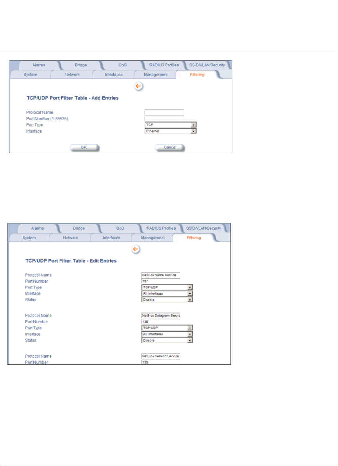
Configuration MeshMAX 5054 Series User Guide
Advanced Configuration of Mesh and Access Point Module
147
Figure 6-34 TCP/UDP Port Filter Table - Add Entries
Editing TCP/UDP Port Filters
1. Click Edit under the TCP/UDP Port Filter Table heading.
2. Make any changes to the Protocol Name or Port Number for a specific entry, if necessary.
3. In the row that defines the port, set the Status to Enable,Disable, or Delete, as appropriate.
4. Select OK.
Figure 6-35 TCP/UDP Port Filter Table - Edit Entries
Alarms
The Alarms tab has the following sub-tabs:
•Groups
•Alarm Host Table
•Syslog
•Rogue Scan

Configuration MeshMAX 5054 Series User Guide
Advanced Configuration of Mesh and Access Point Module
148
Groups
Alarm groups can be enabled or disabled via the Web interface. Place a check mark in the box provided to enable a
specific group. Remove the check mark from the box to disable the alarms. Alarm severity levels are as follows:
•Critical alarms will often result in severe disruption in network activity or an automatic reboot of the AP.
•Major alarms are usually activated due to a breach in the security of the system. Clients cannot be authenticated
because an attempt at unauthorized access into the AP has been detected.
•Informational alarms provide the network administrator with some general information about the activities the AP is
performing.
Configuration Trap Group
Security Trap Group
Trap Name Description Severity Level
oriTrapDNSIPNotConfigured DNS IP address not configured Major
oriTrapRADIUSAuthenticationNotConfigured RADIUS Authentication not configured Major
oriTrapRADIUSAccountingNotConfigured RADIUS Accounting not configured Major
oriTrapDuplicateIPAddressEncountered Another network device with the same IP address
exists
Major
oriTrapDHCPRelayServerTableNotConfigured The DHCP relay agent server table is empty or
not configured
Major
oriTrapVLANIDInvalidConfiguration A VLAN ID configuration is invalid Major
oriTrapAutoConfigFailure Auto configuration failed Minor
oriTrapBatchExecFailure The CLI Batch execution fails for the following
reasons:
• Illegal Command is parsed in the CLI Batch
file
• Execution error is encountered while
executing CLI Batch file
• Bigger file size than 100 Kbytes
Minor
oriTrapBatchFileExecStart The CLI Batch execution begins after file is
uploaded
Minor
oriTrapBatchFileExecEnd The execution of CLI Batch file ends. Minor
Trap Name Description Severity Level
oriTrapInvalidEncryptionKey Invalid encryption key has been detected. Critical