Proxim Wireless MESHMAXMP11R 802.11 a/b/g Access Point User Manual MeshMAX5054Series QIG indd
Proxim Wireless Corporation 802.11 a/b/g Access Point MeshMAX5054Series QIG indd
Contents
Users Manual 1
Part Number 74432 (Print version)
Part Number 74434 (CD version)
Quick Install Guide
MeshMAX 5054 Series

Page 2 Copyright © 2008 Proxim Wireless
NOTICES
© 2008 Proxim Wireless, San Jose, CA. All rights reserved. Covered by one
or more of the following U.S. patents: 5,231,634; 5,875,179; 6,006,090;
5,809,060; 6,075,812; 5,077,753. This User Guide and the software described
in it are copyrighted with all rights reserved. No part of this publication may be
reproduced, transmitted, transcribed, stored in a retrieval system, or translated
into any language in any form by any means without the written permission of
Proxim Wireless Corporation.
All rights reserved Page 31
www.proxim.com
1561 Buckeye Drive, Milpitas
CA-95035
Phone: 408-731-2700

Page 30 Copyright © 2008 Proxim Wireless
TECHNICAL SERVICES AND SUPPORT
If you are having trouble utilizing your Proxim product, please review the
MeshMAX 5054 User Guide amd the additional documentation provided with
your product.
If you require additional support, please refere to the “Technical Services
and Support” chapter in the MeshMAX 5054 User Guide for details about the
information you will need to gather before using the support Options listed
below.
Support Options
Proxim eService Web Site Support
The Proxim eService Web Site is available 7x24x365 at: http://support.proxim.
com/://support.proxim.com.
Telephone Support
Contact technical support via telephone as follows:
US and Canada ▪: 408-383-7700, 866-674-6626 (Toll Free)
Hours of Operations: 8AM - 6.00PM
APAC Countries: ▪ +90 40-23115490
Hours of Operations: 9AM - 6.00PM
International: ▪ 408-383-7700
Hours of Operations: 8AM - 6.00PM
ServPak Support
Proxim understands that service and support requirements vary from customer
to customer. In recognition of these varying requirements we have developed
a support program called ServPak. ServPak is a program of Enchanced Service
Options that can be purchased individually or in combinations to meet your
needs.
Advanced Replacement ▪
Extended Warranty ▪
7x24x365 Technical Supports ▪
Priority Queiuing ▪
To learn more, please call Proxim Support at 408-383-7700 or send an email
to servpak@proxim.com. To purchase ServPak support services, please contact
your authorized Proxim distributor.
All rights reserved Page 3
CONTENTS
Introduction ................................................................... 4
Package Contents ...........................................................6
Hardware and Software Installation ...............................8
Step 1: Choose a Location ......................................................................9
Step 2: Unpack the Shipping Box .......................................................... 10
Step 3: Assemble the Cable .................................................................. 11
Step 4: Assemble Mounting Hardware .................................................... 12
Step 5: Mount the Unit ........................................................................ 13
Step 6: Plug in the Cables .................................................................... 14
Step 7: Power on the Unit .................................................................... 15
Step 8: View LEDs............................................................................... 16
Step 9: Tighten the Cables ................................................................... 17
Step 10: Weatherproof the Connectors .................................................. 18
Step 11: Align the Antenna .................................................................. 19
Step 12: Install Documentation and Software ......................................... 20
Unit Initialization .........................................................21
Mesh Unit Initialization ........................................................................ 21
Subscriber Unit Initialization ................................................................. 28
Technical services and support .....................................30
Support Options .................................................................................. 30

Page 4 Copyright © 2008 Proxim Wireless
INTRODUCTION
The MeshMAX 5054 Series is a ruggedized tri-mode Mesh AP with additional 5
GHz subscriber station functionality. It is optimized for outdoor deployments. It
is equipped with the following embedded modules:
Mesh Module: ▪ One embedded 5 GHz (802.11a) module and one
embedded 2.4 GHz (802.11b/g) module, enabling simultaneous support
of 802.11a, 802.11b, and 802.11g clients. Both radios also support Mesh
operation.
Subscriber Module: ▪One embedded module operating in the unlicensed 5
GHz band to enable high-speed backhaul
The MeshMAX 5054 Series can operate either using PoE with the combination
DC power supply/injector provided or directly from a 100 - 240 VAC power
source (AC cable ordered separately).
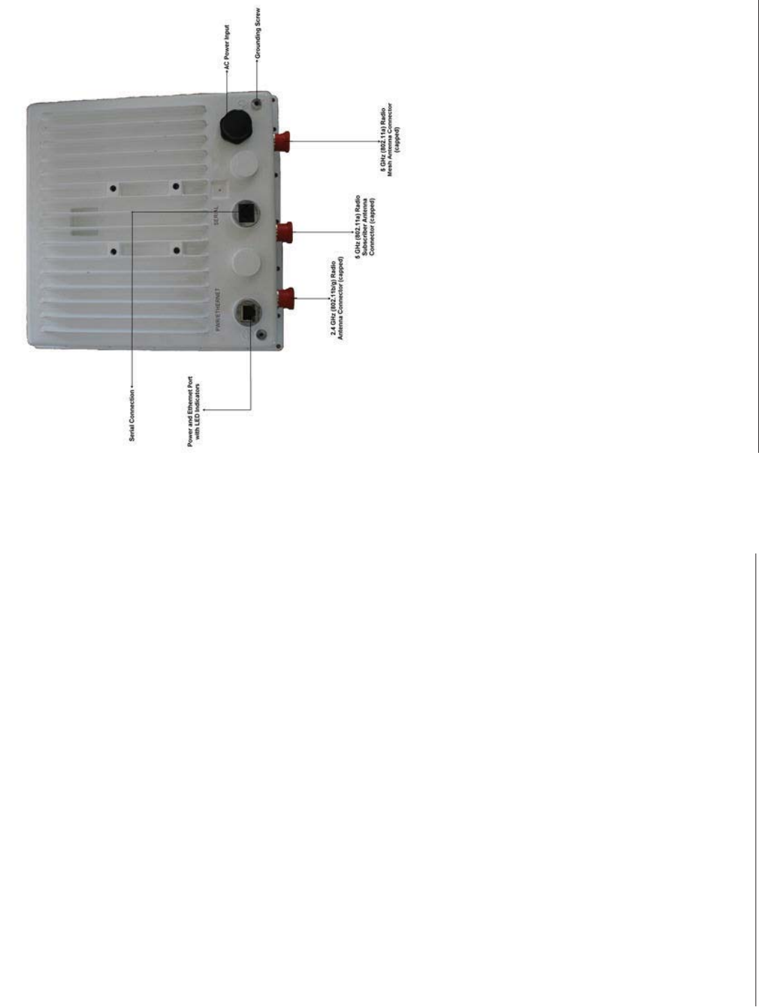
Each unit is equipped with:
Power/Ethernet port: ▪used for Ethernet connection and Power over
Ethernet (PoE) using the supplied power injector.
Serial connection: ▪ used for entering commands in the Command Line
Interface (CLI).
LED indicator(s): ▪dual LEDs used to indicate the power and operational
states of the unit.
AC power input: ▪ enables direct power from external AC power source.
External antenna connectors (three): ▪one for 2.4 GHz client access,
one for 5 GHz Mesh operation, and one 5 GHz Subscriber operation.
Grounding screws (two) ▪
Note:
This product does not contain internal antennas. At least one external
antenna must be used to make the product operational. For information
on antennas authorized for use with this product, refer to the Safety and
Regulatory Compliance Guide on the installation CD.
All rights reserved Page 29
Enter the Read/Write Password (the default value is public) and click OK to
confi rm your changes. The respective module reboots to make the effective.
Accessing the Web Browser
To access the module with a Web Browser:
Start a Web browser (such as Internet Explorer) and enter the IP address of the
module in the Address box (for example, http://10.0.0.1).
A login window is displayed. Do not fi ll in the User name; enter only the
default password public.
Upon successful login, the System Status window is displayed.
Accessing the Command Line Interface
The CLI is accessible through the Serial RS-232 cable connected through the
network, or with a cross-over Ethernet cable between the computer and the
module’s serial port.
Ethernet Port
To use the CLI through the Ethernet port, you must have a telnet program, and
the module’s IP address.
To access the unit through Ethernet on a Windows PC:
Open a DOS command window: from the Windows Start menu, Select Run;
enter cmd.
In the DOS window displayed, enter telnet and IP address (for example, telnet
10.0.0.1) and type <enter>. You will be prompted for your password. Enter the
password (the default is public).
Y-Cable
The Y-cable has two DB9 connectors which connect to the RJ11. The long one
connects to the Mesh console and the short one to the Subscriber console.
Page 28 Copyright © 2008 Proxim Wireless
Subscriber Initialization
Connecting to the module requires either:
A direct physical connection with an Ethernet cable or with a serial RS-32 ▪
cable
A network connection ▪
Connecting with the Ethernet cable allows you to access the unit through a
terminal emulation program, such as HyperTerminal. (See “HyperTerminal
Connection Properties” in the MeshMAX 5054 User Guide.
Setting the IP Address
With ScanTool (a software utility that is included on the product installation
CD), you can fi nd out the current IP address of the unit and, if necessary,
change it so that is appropriate for your network.
ScanTool lets you fi nd the IP address of a module by referencing the MAC
address in a Scan List, or to assign an IP address if the correct one has not
been assigned. The tool automatically detects the units installed on your
network segment, regardless of IP address, and lets you confi gure each unit’s
IP settings. In addition, you can use ScanTool to download new software to a
unit that does not have a valid software image installed.
To discover and set/change the IP address of the unit:
Run ScanTool on a computer connected to the same LAN subnet as the unit, or
a computer directly connected to the module with a cross-over Ethernet cable.
Double-click the ScanTool icon on the Windows desktop to launch the program.
If the icon is not on your desktop, click Start > All Programs > MeshMAX
5054 series > ScanTool.
ScanTool scans the subnet and displays the module it fi nds in the main window.
If necessary, click Rescan to re-scan the subnet and update the display. You
can assign a new IP address to one module, even if more than one module has
the same (default) IP address 10.0.0.1, but the new IP address must be unique
to allow the use of the management interfaces.
Select the module for which you want to set the IP address and click Change.
The Change dialog window is displayed.
To set the IP address manually, ensure that Static is selected as the IP
Address Type and fi ll in the IP Address and Subnet Mask suitable for the
LAN subnet to which the uni is connected.
To set the IP address dynamically, ensure that Dynamic is selected as the IP
Address Type. The module will request its IP address from a DHCP server on
your network.
All rights reserved Page 5
Figure 1: MeshMAX 5054 Unit
Page 6 Copyright © 2008 Proxim Wireless
PACKAGE CONTENTS
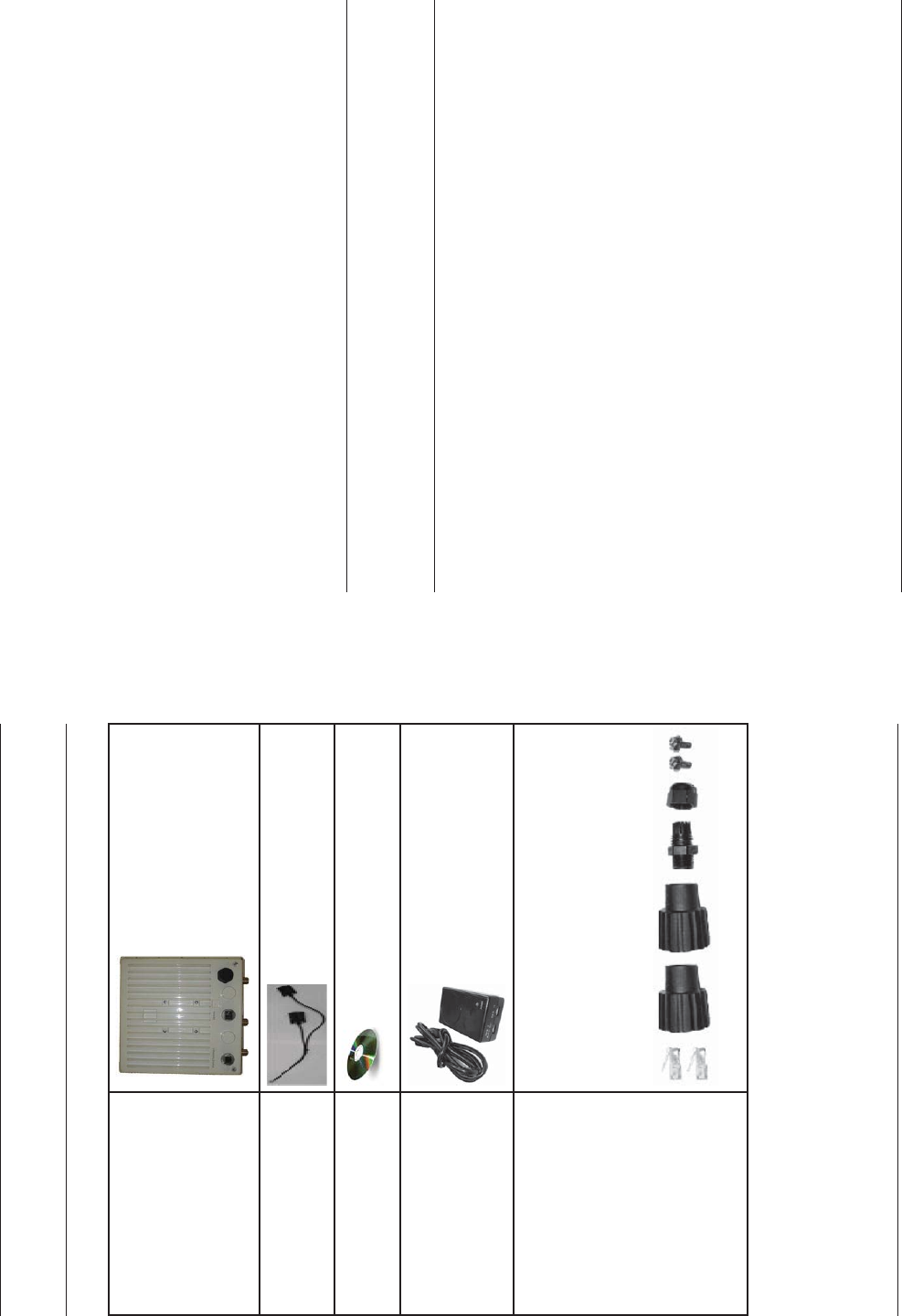
Each shipment includes the items in the following table. Verify that you have
received all parts of the shipment.
Note:
Unless listed here, cables are not included with the unit.
MeshMAX 5054 Unit
Y-cable connector
Installation CD (1 ea.)
Power Injector and Cord
(1 ea.)
Cable Termination Kit Kit includes:
A. RJ45 connectors (2)
B. Sealing caps (2)
C. Lock nut
D. Sealing nut
E. Grounding screws (2)
A B C D E
All rights reserved Page 27
From the 3. File Type drop-down menu, select Image.
Use the 4. Browse button to locate or manually type in the name of the
fi le (including the fi le extension) you downloaded from the Proxim
Knowledgebase. If typing the fi le name, you must include the full path and
the fi le extension in the fi le name text box.
To initiate the HTTP Update operation, click the 5. Update AP button. A
warning message advises you that a reboot of the device will be required
for changes to take effect.
Click 6. OK to continue with the operation or Cancel to abort the operation.
If the operation is unsuccessful, you will receive an error message. See 7.
the MeshMAX 5054 User Guide for more information. If the operation is
successful, you will receive a confi rmation message.
Reboot the Mesh radio as follows:8.
Click a. Commands > Reboot.
Enter b. 0 in the Time to Reboot fi eld.
Click c. OK.
Note:
For instructions on downloading the software via a TFTP Server or the CLI
Interface, see the MeshMAX 5054 User Guide.

Page 26 Copyright © 2008 Proxim Wireless
Software Updates
Proxim periodically releases updated software for the MeshMAX 5054 on its
support Web site, http://support.proxim.com. Proxim recommends that you
check the Web site for the latest updates after you have installed and initialized
the unit.
Download the Software
In your web browser, go to 1. http://support.proxim.com.
If prompted, create an account to gain access.2.
Note:
The Knowledgebase is available to all Web site visitors. First-time users will
be asked to create an account to gain access.
Click3. Search Knowledgebase.
In the 4. Search Knowledgebase fi eld, enter 2763.
Click 5. Search.
Click on the link in the 6. Summary column to access the download page.
Click on the appropriate link to download the software. 7.
Install the Software
Enter the Access Point’s IP address in the browser’s Address fi eld and press 1.
Enter or Go.
Click 2. Commands > Update AP > via HTTP. The Update AP via HTTP
screen will be displayed.
All rights reserved Page 7
Mounting Kit Kit includes the following:
A. Mounting clamp for wall/pole
B. Extension arm
C. Mounting plate to enclosure
D. Mounting clamp for pole mounting
A B C D
Mounting Hardware The following mounting hardware is included
with mounting kit:
Qty. Description
6 ea Plain washer #5/16
2 ea. Hex cap screw NC 5/16-18 x 35
2 ea. Nut NC 5/16-18
4 ea. Helical spring lock washer # 1/4
4 ea. Helical spring lock washer #5/16
2 ea Hex cap screw NC 5/16-18 x 80
4 ea. 68764, Screw, Machine, Pan,
Phillips, 1/4”-20, 5/8”L
Rubber Tape Strip

Page 8 Copyright © 2008 Proxim Wireless
HARDWARE AND SOFTWARE INSTALLATION
Notes:
Be sure to read the Release Notes fi le on the product CD as it contains ▪
software version and driver information that may not have been available
when this document was produced.
Equipment is to be used with, and powered by, the power injector provided ▪
or by a power injector that meets these requirements:
UL-Listed/ITE (NWGQ) –
Limited Power Source Output per UL/IEC 60950 –
CE-marked –
Approved for Power-over-Ethernet –
Rated output, 48 Vdc/0.42 A –
Pinout follows 802.3af standard for mid-span devices –
IMPORTANT!
Before installing this product, see Safety and Regulatory Compliance
Information on the product CD for important information.
IMPORTANT!
All units must be installed by a suitably trained professional installation
technician or by a qualifi ed installation service.
WARNING!
To ensure proper grounding, use the hole at the bottom point on the back
of each unit and the provided grounding screws to attach a ground wire of
at least 10 AWG stranded to each unit. Use proper wire grounding tech-
niques in accordance with local electric codes.
All rights reserved Page 25
Click Setup Wizard to begin. The Setup Wizard supports the following 1.
navigation options:
Save & Next Button ▪: Each Setup Wizard screen has a Save & Next
button. Click this button to submit any changes you made to the unit’s
parameters and continue to the next page. The instructions below
describe how to navigate the Setup Wizard using the Save & Next
buttons.
Navigation Panel ▪: The Setup Wizard provides a navigation panel
on the left-hand side of the screen. Click the link that corresponds to
the parameters you want to confi gure to be taken to that particular
confi guration screen. Note that clicking a link in the navigation panel
will not submit any changes you made to the unit’s confi guration on the
current page.
Exit ▪: To exit from the Setup Wizard at any time, click Step 1:
Introduction on the navigation panel, and then click the Exit button.
CAUTION:
If you exit from the Setup Wizard, any changes you submitted (by
clicking the Save & Next button) up to that point will be saved to the
unit but will not take effect until it is rebooted.
Follow the prompts provided by the Setup Wizard to perform an initial 2.
confi guration of the Mesh radio. See the MeshMAX 5054 User Guide for
more detailed Setup Wizard instructions and for advanced confi guration
instructions.

Page 24 Copyright © 2008 Proxim Wireless
Open a Web browser on a network computer. 1.
If necessary, disable the browser’s Internet proxy settings. 2.
Enter the Access Point’s IP address in the browser’s 3. Address fi eld and
press Enter or Go. This is either the dynamic IP address assigned by a
network DHCP server or the static IP address you manually confi gured. See
the Using ScanTool section above for information on how to determine the
unit’s IP address and manually confi gure a new IP address, if necessary.
The login screen appears.4.
Enter the HTTP password in the 5. Password fi eld. Leave the User Name
fi eld blank. For new units, the default HTTP password is public.
If you are logging on for the fi rst time the Setup Wizard will launch
automatically.
Note
Setup Wizard will not relaunch on subsequent logins. To force the Setup
Wizard to launch upon login, click Management > Services and choose
Enable from the Setup Wizard drop down menu.
To confi gure the Mesh radio using the Setup Wizard, see 6. Using the Setup
Wizard, below. To confi gure the radio without using the Setup Wizard,
click Exit. Upon clicking Exit, the System Status screen will appear. See
the “Advanced Confi guration” chapter in the MeshMAX 5054 User Guide for
confi guration instructions.
Using the Setup Wizard
The Setup Wizard provides step-by-step instructions for how to confi gure
the Access Point’s basic operating parameters, such as Network Name, IP
parameters, system parameters, and management passwords.
All rights reserved Page 9
Step 1: Choose a Location
To make optimal use of the unit, you must fi nd a suitable location for the
hardware. The range of the radio unit largely depends upon the position of the
antenna. Proxim recommends you do a site survey, observing the following
requirements, before mounting the hardware.
The location must allow easy disconnection of power to the radio if ▪
necessary.
Air must be able to fl ow freely around the hardware. ▪
The radio unit must be kept away from vibration and excessive heat. ▪
The installation must conform to local regulations at all times. ▪
The unit is designed to directly mount to a pole or wall. Using the supplied
mounting clamps and hardware, you can mount the unit to a 1.25 inch to 4.5-
inch pole (outside diameter). Using just one of the mounting clamps brackets,
you can mount it to a wall or other fl at surface.
Caution!
Proxim recommends the use of a lightning arrestor at the building
ingress point. You can purchase the Proxim Lightning Protector; see
the documentation that comes with the Lightning Protector for more
information and installation instructions.

Page 10 Copyright © 2008 Proxim Wireless
Step 2: Unpack the Shipping Box
Unpack the unit and accessories from the shipping box.1.
Note the Ethernet and wireless MAC addresses of the unit, as well as the 2.
serial number. The serial number is required to obtain support from Proxim.
Keep this information in a safe place.
All rights reserved Page 23
Set c. IP Address Type to Static.
Enter a static IP Address for the Mesh radio in the fi eld provided. d.
You must assign the unit a unique address that is valid on your IP
subnet.
Enter your network’s e. Subnet Mask.
Enter your network’s f. Gateway IP Address.
Enter the SNMP read/write password in the g. Read/Write
Password fi eld. For new units, the default password is public.
Click h. OK to save your changes.
The Access Point will need to reboot to apply any changes you i.
made. When the reboot message appears, click OK to reboot the
device and return to the Scan List screen.
After allowing suffi cient time for the device to reboot, click j.
Rescan to verify that your changes have been applied.
Click the k. Change button to return to the Change screen.
Click the l. Web Confi guration button at the bottom of the
Change screen.
Proceed to the m. Logging In section, below.
Logging In
Once the Mesh radio has a valid IP Address, you may use your web browser
to monitor and confi gure the Mesh radio. (To confi gure and monitor using the
command line interface, see the MeshMAX 5054 User Guide.)
Page 22 Copyright © 2008 Proxim Wireless
Note:
If your unit does not appear in the Scan List, click the Rescan button
to update the display. If the unit still does not appear in the list, see the
Troubleshooting chapter in the MeshMAX 5054 User Guide for suggestions.
Note that after rebooting an Access Point, it may take up to fi ve minutes for
the unit to appear in the Scan List.
Do one of the following:4.
If the Mesh radio has been assigned an IP address by a DHCP server on ▪
the network:
Highlight the entry for the unit you want to confi gure.a.
Click the b. Change button. The Change screen appears (see
below).
Click on the c. Web Confi guration button at the bottom of the
change screen.
Proceed to the d. Logging In section, below.
If the Mesh radio has not been assigned an IP address (in other words, ▪
the unit is using its default IP address, 169.254.128.132), follow these
steps to assign it a static IP address that is valid on your network:
Highlight the entry for the unit you want to confi gure.a.
Click the b. Change button. The Change screen appears.
All rights reserved Page 11
Step 3: Assemble the Cable
Use the Cable Termination Kit to assemble the cable. You will be attaching an
outdoor-rated 24 AWG CAT5 cable (diameter .114 to .250 inches/2.9 to 6.4
mm) (not provided) to the Power-over-Ethernet port on the back of the unit
and weatherproofi ng the assembly later in the installation procedure. First, you
must construct the cable and assemble the weatherproofi ng cable covers as
described in the following steps. Proxim greatly simplifi es this assembly process
by offering pre-assembled CAT5 cable kits in 25m, 50m, and 75m lengths (part
numbers 69819, 69820, and 69821, respectively).
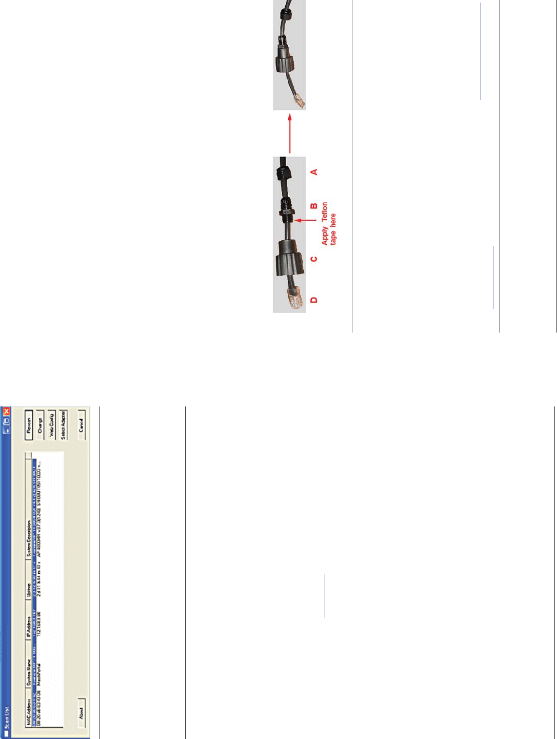
Slide the sealing nut (A) over the bare end of the CAT5 cable.1.
Slide the lock nut (B) over the bare end of the CAT5 cable.2.
Slide the sealing cap (C) over the bare end of the CAT5 cable. Make sure 3.
the red rubber gasket is inside the cap.
Apply two wraps of 0.5” wide Tefl on tape (not supplied with unit) around 4.
the threads of the lock nut (B) that will go inside the sealing cap.
Thread the lock nut (B) onto the sealing cap (C), and hand tighten.5.
Terminate the RJ45 connectors (D) to both ends of the CAT5 cable; test for 6.
proper wiring (using a straight-through cable).
Notes:
The cable must feed through all parts of the weatherproof cap before the ▪
RJ45 is crimped on the outdoor Ethernet cable.
The cable between the power injector and the unit must be a straight- ▪
through Ethernet cable (without crossover).
Due to variance in CAT5 cable diameter, termination techniques of the ▪
installer, and the application of proper tightness of the connectors, it is
strongly recommended that all cable connectors are secured by external
weatherproofi ng. This process will be described in Step 10: Weatherproof
the Connectors.
Page 12 Copyright © 2008 Proxim Wireless
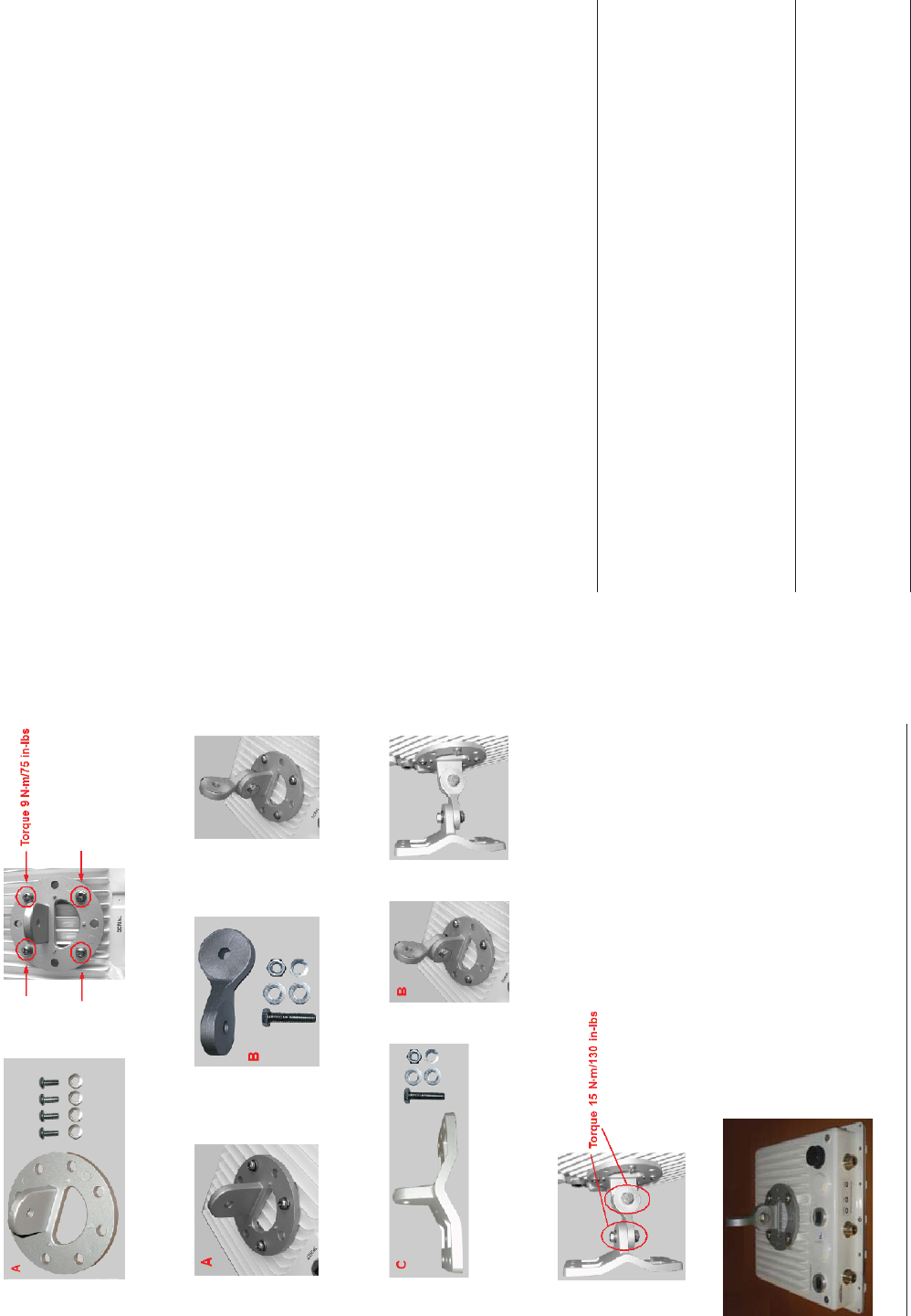
Step 4: Assemble Mounting Hardware
Attach the mounting plate (A) using the provided screws and washers 1.
(Torque 9 N∙m/75 in-lbs)
Attach the extension arm (B) to mounting piece (A) with the screw, nut, 2.
and washers.
Attach the mounting bracket (C) to extension arm (B) with the screw, nut, 3.
and washers provided.
Tighten assembly (Torque 15 N∙m/130 in-lbs).4.
The following fi gure shows the full assembly attached to the unit.
All rights reserved Page 21
UNIT INITIALIZATION
Mesh Initialization
Using ScanTool
ScanTool is a software utility that is included on the installation CD-ROM. It is
an initial confi guration tool that allows you to fi nd the IP address of an Access
Point by referencing the MAC address in a Scan List, or to assign an IP address
if one has not been assigned.
The tool automatically detects the MeshMAX units installed on your network,
regardless of IP address, and lets you confi gure each unit’s IP settings. In
addition, you can set initial device parameters that will allow the Mesh radio to
retrieve a new software image if a valid software image is not installed.
To access the HTTP interface and confi gure the Mesh unit, the unit must be
assigned an IP address that is valid on its Ethernet network. By default, the
Mesh unit is confi gured to obtain an IP address automatically from a network
Dynamic Host Confi guration Protocol (DHCP) server during boot-up. If your
network contains a DHCP server, you can run ScanTool to fi nd out what IP
address the Mesh radios have been assigned. If your network does not contain
a DHCP server, the IP address for the Mesh radios defaults to 169.254.128.132.
In this case, you can use ScanTool to assign the unit a static IP address that is
valid on your network.
Scan Tool Instructions
Power up, reboot, or reset the unit.1.
Double-click the ScanTool icon on the Windows desktop to launch the 2.
program. If the icon is not on your desktop, click Start > All Programs >
Proxim > MeshMAX 5054 > ScanTool.
Note:
If your computer has more than one network adapter installed, you will be
prompted to select the adapter that you want ScanTool to use before the
Scan List appears. You can use either an Ethernet or wireless adaptor.
If prompted, select an adapter and click OK. You can change your adapter
setting at any time by clicking the Select Adapter button on the Scan List
screen.
ScanTool scans the subnet and displays all detected units. The ScanTool’s
Scan List screen appears, as shown in the following example.
Page 20 Copyright © 2008 Proxim Wireless
Step 12: Install Documentation and Software
To install the documentation and software on a computer or network:
Place the installation CD in a CD-ROM drive. The installer normally starts 1.
automatically. (If the installation program does not start automatically, click
setup.exe on the installation CD).
Follow the instructions displayed on the installer windows. 2.
All rights reserved Page 13
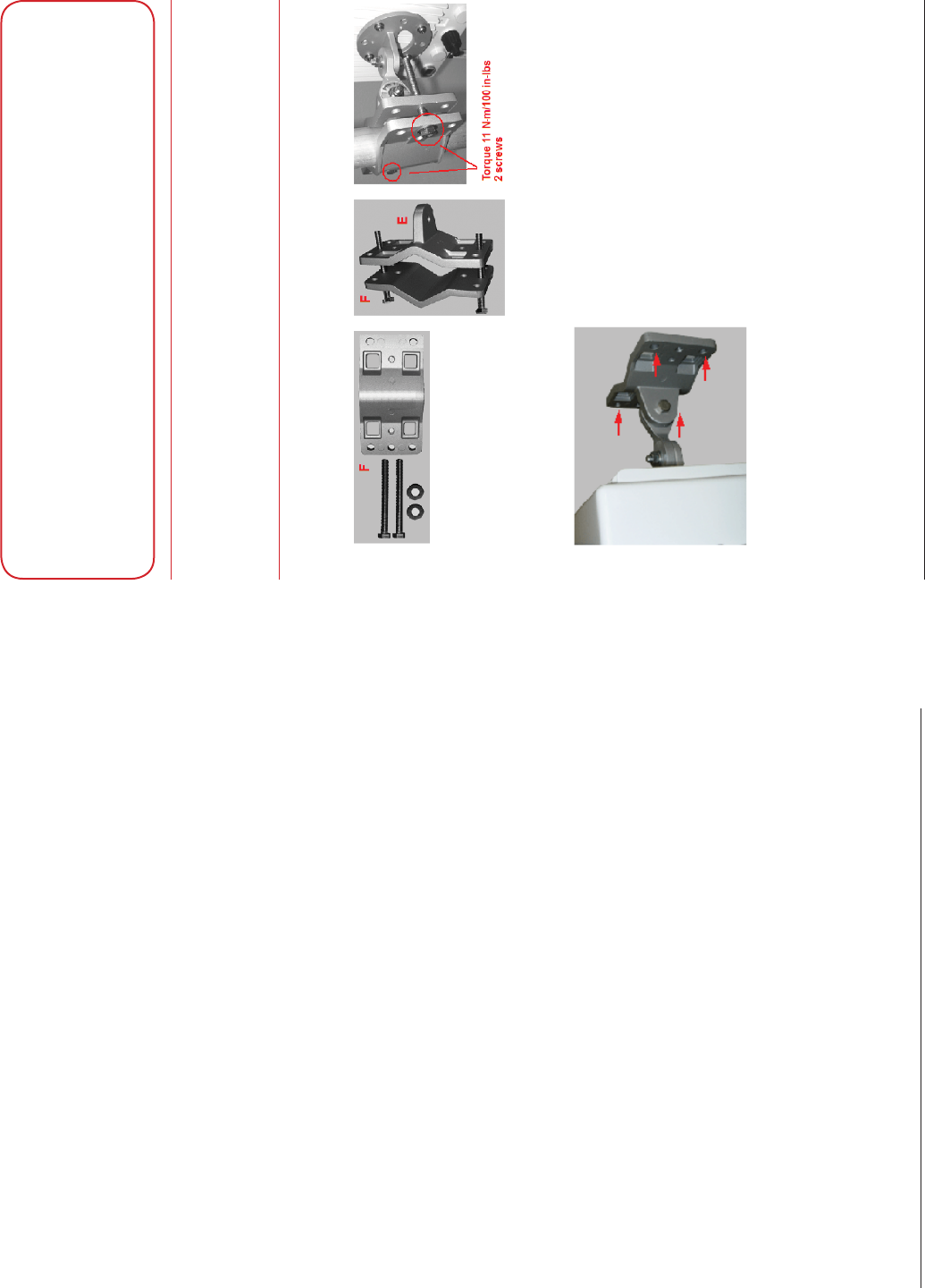
Step 5: Mount the Unit
Caution:
To ensure that water does not gather around the antenna
connectors, mount the unit with the antenna connectors facing
downward.
To pole-mount, insert the provided screws through bracket F. Fasten around 1.
the pole to bracket E and secure (Torque 11 N.m/100 in-lbs).
To wall-mount the unit, mount bracket (E) to the wall using 4 screws (not 2.
provided), as shown.
IMPORTANT!
If the unit is going to be used as part of a Mesh network, you will need to
perform initial confi guration of the parameters mentioned in the Pre-
requisites section of this MeshMAX 5054 User Guide before you mount
the unit. See the User Guide for more information on confi guring these
parameters.

Page 14 Copyright © 2008 Proxim Wireless
Step 6: Plug in the Cables
Plug one end of the CAT5 cable (A) into the RJ45 jack of the unit (B).1.
Connect the free end of the CAT5 cable to the “Data and Power Out” port 2.
on the power injector.
To connect the unit through a hub or a switch to a PC, connect a straight-3.
through Ethernet cable between the network interface card in the PC and
the hub, and between the hub and the RJ45 “Data In” port on the PoE
adapter.
To connect the unit directly to a PC, connect a cross-over Ethernet cable
between the network interface card in the PC and the RJ45 “Data In” port
on the power injector.
If you are connecting the PC directly to the unit, use a crossover Ethernet
cable between the network interface card in the PC and the RJ45 “Data In”
port on the power injector.
All rights reserved Page 19
Step 11: Align the Antenna
Antenna Alignment Display (AAD) provides a measurement of signal quality in
an easy-to-interpret manner - a numeric printed signal value at the CLI amd
serial ports. The SNR is numerically displayed on the CLI serial port by two
decimal charaters representing a number from 00 to 99. On the serial port, AAD
is enabled by default after booting.
To start the display, you must enable AAD and a wireless link must be
established between the BSU and the SU.
Aiming is complete if moving in any direction results in a falling SNR value.
Antenna alignment commands
The following CLI commands are used to initiate and stop the antenna
alignment process. After the process has been successfully initiated, the CLI
displays the current-local/current-remote/average SNR values (in 500 ms
intervals) to indicate the link quality.
Set aad enable local
Enables display of the local SNR (the SNR as measured by the receiver at the
far end).
Set aad enable remote
Enables display of the remote SNR (the SNR as measured by the receiver at the
far end).
Set aad enable average
Enables display of the remote SNR (the average of local and remote SNR).
Set aad disable
Disables Antenna Alignment Display (Ctrl-C also disables AAD).

Page 18 Copyright © 2008 Proxim Wireless
Step 10: Weatherproof the Connectors
After you have fully assembled and tightened the cable, use the provided
self-fusing, rubber-based tape strip and electrical tape (not provided; Proxim
recommends Scotch™ Super 33+ Vinyl Electrical Tape) to seal the connection,
as follows.
Remove the fi lm liner from the rubber-based tape strip, and stretch the 1.
tape until it is approximately half of its original width. This activates the
self-fusing action of the tape, which will set up over time to create a single,
waterproof mass.
Stretch and wrap the tape around the connector tightly, starting below the 2.
connector cap and against the unit and wrapping in a clockwise direction.
Wrap the tape once around the base of the connector cap (A). Continue
to wrap the tape spirally around the connector in a clockwise direction,
maintaining a 50% width overlap (B). Continue wrapping the tape spirally
upward (C) until the tape extends onto the cable and you have used the
entire length of tape. Seal the tape tightly against the connector and the
cable (D).
Note:
Be sure to wrap the tape in a clockwise direction; wrapping the tape in a
counterclockwise direction may loosen up the connector.
In the same manner as described in Step 2 above, apply a layer of black 3.
electrical tape (not provided) over the rubber-based tape for further
protection. Make sure the electrical tape also extends beyond the rubber-
based tape to seal it.
Repeat the weatherproofi ng procedure for other connectors as appropriate.4.
All rights reserved Page 15
Step 7: Power on the Unit
The power injector provides Power-over-Ethernet (PoE), supplying electricity
and wired connectivity to the unit over a single 24 AWG CAT5 (diameter .114 to
.250 inches/2.9 to 6.4 mm). The unit is not 802.3af-compatible. Always use the
supplied power injector to ensure that the unit is powered properly. Note that
the Active Ethernet module provides +48 VDC over a standard CAT5 Ethernet
cable.
Once you have connected the power injector to the Ethernet cabling and
plugged the power injector cord into an AC outlet, the unit is powered on.
There is no ON/OFF switch on the unit. To remove power, unplug the AC cord
from the AC outlet or disconnect the RJ45 connector from the “Data and Power
Out” port on the power injector.
Press the Reload button (on the side of the power injector) for fi ve seconds
during power-up remotely resets the Mesh radios to their factory default
settings. You will need to use the end of a pin or paperclip to depress the
button.
WARNING!
To avoid damaging your router/switch, do not connect the RJ45
port labeled either “Data & Power Out” from the power injector to
your router/switch.
Press the Reload button (on the side of the power injector) to intiate the
Reload/Reset functionality. You may have to use the end of a pin or paperclip to
press the button.
If the Reload button is pressed for 5 to 10 seconds and then released, then
Mesh module moves to the bootloader state. If Reload button is pressed beyond
10 seconds, then the Mesh module’s Reload functionality is ignored.
If the Reload button is pressed for 10 to 20 sconds and released, then none of
the operation is performed and the Reload button is aborted.
If the Reload button is pressed for 20 seconds and above, then the Subscriber
module moves to reload state.
NOTE:
Bootloader will display all events to the serial console, which will guide user to
perform the Reload functionality.
Page 16 Copyright © 2008 Proxim Wireless
Step 8: View LEDs
The LEDs are present at the unit’s Ethernet connector; unscrew the watertight
cap if necessary to view the LEDs.
NOTE:
Make sure the domed sealing nut is loose before unscrewing the cap or the
Ethernet cable may be twisted and damaged.
When the unit is powered on, it performs startup diagnostics. When startup is
complete, the LEDs show the unit’s operational state, as follows:
LED State Power/Ethernet LED Radio LED
Blinking Green Power is on, unit is booting up,
Ethernet link is down.
Mesh radios are being initialized.
Steady Green Power is on, Ethernet link is up. Mesh radios are being
operational.
All rights reserved Page 17
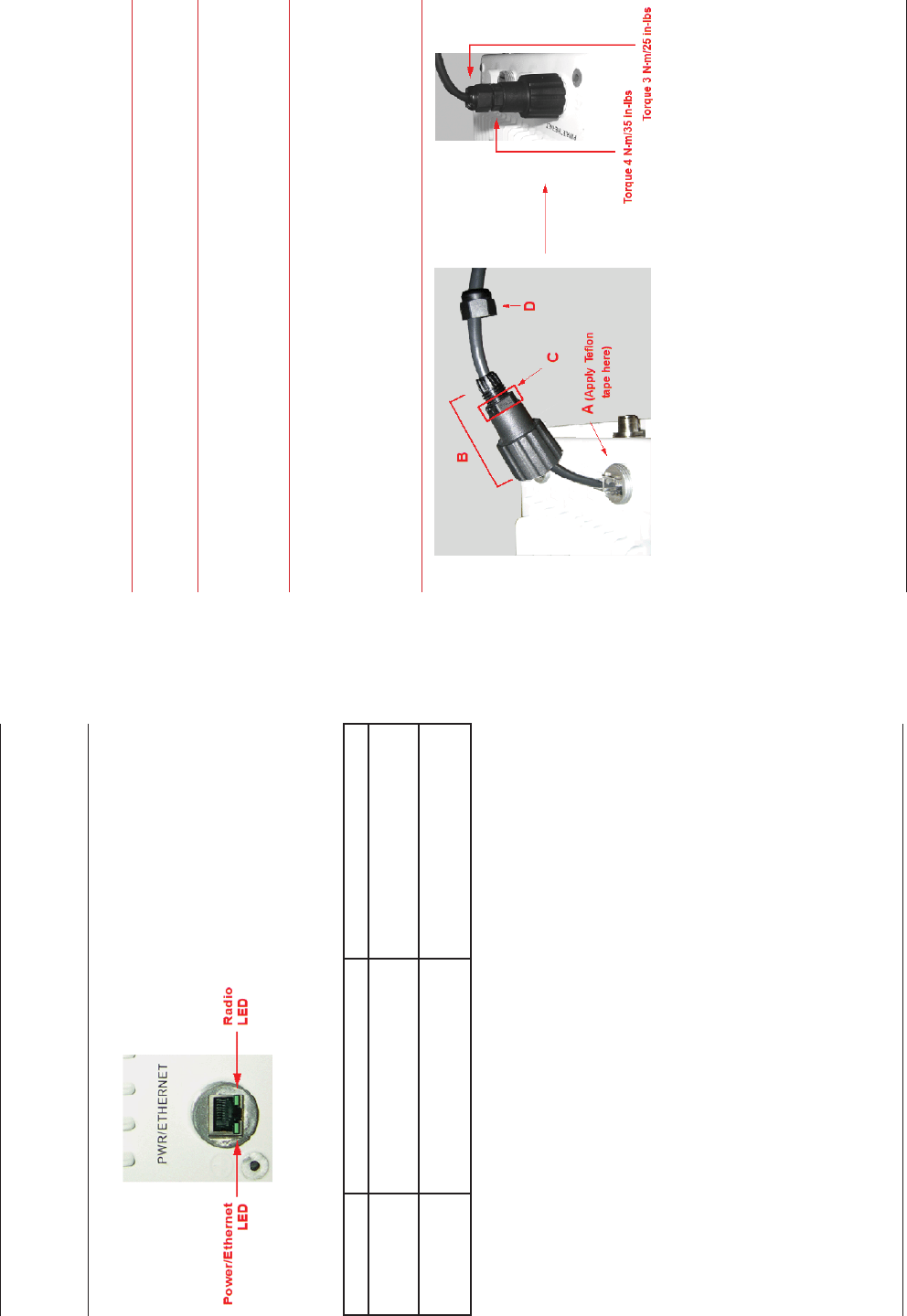
Step 9: Tighten the Cables
Apply two wraps of Tefl on tape around the threads of the unit’s RJ45 jack 1.
(A) in a clockwise direction.
Make sure that the red rubber gasket is still seated in the sealing cap of the 2.
sealing cap/lock nut assembly (B).
Slide the sealing cap/lock nut assembly (B) over the RJ45 jack (A) and 3.
thread onto enclosure. Hand tighten fi rst, then use a pipe wrench or similar
tool to tighten one more quarter turn.
Caution!
Do not over-tighten!
Tighten the lock nut (C) (Torque 4 N.m/35 in-lbs).4.
Thread the sealing nut (D) onto the sealing cap/lock nut assembly (B) and 5.
tighten (Torque 3 N.m/25 in-lbs).
Caution!
The lock nut (C) on the sealing cap/lock nut assembly (B) must
be fully tightened over the RJ45 connector before the sealing nut
(D) is fully tightened. Otherwise, the Ethernet cable may twist and
damage.