Proxim Wireless MESHMAXMP11R 802.11 a/b/g Access Point User Manual MP11 RecAntennas
Proxim Wireless Corporation 802.11 a/b/g Access Point MP11 RecAntennas
Contents
Users Manual 3

ORiNOCO Series System
Recommended Antennas

ORiNOCO Series System Recommended Antennas
4
Copyright
©2008 Proxim Wireless Corporation, San Jose, CA. All rights reserved. Covered by one or more of the following U.S. patents: 5,231,634;
5,875,179; 6,006,090; 5,809,060; 6,075,812; 5,077,753. This manual and the software described herein are copyrighted with all rights
reserved. No part of this publication may be reproduced, transmitted, transcribed, stored in a retrieval system, or translated into any language
in any form by any means without the written permission of Proxim Wireless Corporation.Trademarks
Trademarks
Tsunami, Proxim, and the Proxim logo are trademarks of Proxim Wireless Corporation. All other trademarks mentioned herein are the property
of their respective owners.
Safety and Regulatory Information
See the MeshMAX 5054 Series product CD for important Safety and Regulatory information.
ORiNOCO Series System Recommended Antennas
P/N 73923, August 2008

ORiNOCO Series System Recommended Antennas
5
1 Introduction. . . . . . . . . . . . . . . . . . . . . . . . . . . . . . . . . . . . . . . . . . . . . . . . . . . . . . . . . . . . . . . . . . 7
Who Should Use This Guide . . . . . . . . . . . . . . . . . . . . . . . . . . . . . . . . . . . . . . . . . . . . . . . . . . . . . . . . . . . . 7
Antenna Types . . . . . . . . . . . . . . . . . . . . . . . . . . . . . . . . . . . . . . . . . . . . . . . . . . . . . . . . . . . . . . . . . . . . . . . 9
Omni-Directional Antennas . . . . . . . . . . . . . . . . . . . . . . . . . . . . . . . . . . . . . . . . . . . . . . . . . . . . . . . . . . . . . . . . . . . 9
Flat Panel Directional Antennas. . . . . . . . . . . . . . . . . . . . . . . . . . . . . . . . . . . . . . . . . . . . . . . . . . . . . . . . . . . . . . . 10
Sector Antennas. . . . . . . . . . . . . . . . . . . . . . . . . . . . . . . . . . . . . . . . . . . . . . . . . . . . . . . . . . . . . . . . . . . . . . . . . . . 10
Parabolic Dish Antennas . . . . . . . . . . . . . . . . . . . . . . . . . . . . . . . . . . . . . . . . . . . . . . . . . . . . . . . . . . . . . . . . . . . . .11
Summary . . . . . . . . . . . . . . . . . . . . . . . . . . . . . . . . . . . . . . . . . . . . . . . . . . . . . . . . . . . . . . . . . . . . . . . . . . . . . . . . .11
2 Recommended 900 MHz Antennas and Accessories . . . . . . . . . . . . . . . . . . . . . . . . . . . . . . . 12
Omni Antennas . . . . . . . . . . . . . . . . . . . . . . . . . . . . . . . . . . . . . . . . . . . . . . . . . . . . . . . . . . . . . . . . . . . . . 12
Sector Antennas . . . . . . . . . . . . . . . . . . . . . . . . . . . . . . . . . . . . . . . . . . . . . . . . . . . . . . . . . . . . . . . . . . . . . 12
Panel Antennas . . . . . . . . . . . . . . . . . . . . . . . . . . . . . . . . . . . . . . . . . . . . . . . . . . . . . . . . . . . . . . . . . . . . . 13
Cavity Filters . . . . . . . . . . . . . . . . . . . . . . . . . . . . . . . . . . . . . . . . . . . . . . . . . . . . . . . . . . . . . . . . . . . . . . . 13
3 Recommended 2.4 GHz Antennas . . . . . . . . . . . . . . . . . . . . . . . . . . . . . . . . . . . . . . . . . . . . . . 14
Omni Antennas . . . . . . . . . . . . . . . . . . . . . . . . . . . . . . . . . . . . . . . . . . . . . . . . . . . . . . . . . . . . . . . . . . . . . 14
5 dBi Omni-Directional Vehicle Antenna (848 515 722). . . . . . . . . . . . . . . . . . . . . . . . . . . . . . . . . . . . . . . . . . . . . 14
7 dBi Omni-Directional Base Station Antenna (848 312 591) . . . . . . . . . . . . . . . . . . . . . . . . . . . . . . . . . . . . . . . . 16
10 dBi Omni-Directional Base Station Antenna (848 515 698) . . . . . . . . . . . . . . . . . . . . . . . . . . . . . . . . . . . . . . . 18
Sector Antennas . . . . . . . . . . . . . . . . . . . . . . . . . . . . . . . . . . . . . . . . . . . . . . . . . . . . . . . . . . . . . . . . . . . . . 20
12 dBi Directional Wide Angle Antenna (120°) (848 515 706). . . . . . . . . . . . . . . . . . . . . . . . . . . . . . . . . . . . . . . . 20
14 dBi Sector Antenna (60°) (2400-SA60-14) . . . . . . . . . . . . . . . . . . . . . . . . . . . . . . . . . . . . . . . . . . . . . . . . . . . . 22
Panel Antennas . . . . . . . . . . . . . . . . . . . . . . . . . . . . . . . . . . . . . . . . . . . . . . . . . . . . . . . . . . . . . . . . . . . . . 24
14 dBi Directional Panel Antenna (1086-PA24-14) . . . . . . . . . . . . . . . . . . . . . . . . . . . . . . . . . . . . . . . . . . . . . . . . 24
Parabolic Antennas . . . . . . . . . . . . . . . . . . . . . . . . . . . . . . . . . . . . . . . . . . . . . . . . . . . . . . . . . . . . . . . . . . 26
24 dBi Directional Parabolic Grid Antenna (848 515 714) . . . . . . . . . . . . . . . . . . . . . . . . . . . . . . . . . . . . . . . . . . . 26
4 Recommended 4.9 GHz Antennas . . . . . . . . . . . . . . . . . . . . . . . . . . . . . . . . . . . . . . . . . . . . . . 28
Omni Antennas . . . . . . . . . . . . . . . . . . . . . . . . . . . . . . . . . . . . . . . . . . . . . . . . . . . . . . . . . . . . . . . . . . . . . 28
8 dBi Omni-Directional Antenna (1086-OA49-8) . . . . . . . . . . . . . . . . . . . . . . . . . . . . . . . . . . . . . . . . . . . . . . . . . . 28
10 dBi Omni-Directional Antenna (1086-OA49-10) . . . . . . . . . . . . . . . . . . . . . . . . . . . . . . . . . . . . . . . . . . . . . . . . 30
Panel Antennas . . . . . . . . . . . . . . . . . . . . . . . . . . . . . . . . . . . . . . . . . . . . . . . . . . . . . . . . . . . . . . . . . . . . . 32
10 dBi Panel Antenna (1086-PA49-10) . . . . . . . . . . . . . . . . . . . . . . . . . . . . . . . . . . . . . . . . . . . . . . . . . . . . . . . . . 32
21 dBi Panel Antenna (1086-PA49-21) . . . . . . . . . . . . . . . . . . . . . . . . . . . . . . . . . . . . . . . . . . . . . . . . . . . . . . . . . 34
Sector Antennas . . . . . . . . . . . . . . . . . . . . . . . . . . . . . . . . . . . . . . . . . . . . . . . . . . . . . . . . . . . . . . . . . . . . . 36
14 dBi Sector Antenna (120°) (5054-SA120-14) . . . . . . . . . . . . . . . . . . . . . . . . . . . . . . . . . . . . . . . . . . . . . . . . . . 36
17 dBi Sector Antenna (60°) (5054-SA60-17) . . . . . . . . . . . . . . . . . . . . . . . . . . . . . . . . . . . . . . . . . . . . . . . . . . . . 38
5 Recommended 5 GHz Antennas . . . . . . . . . . . . . . . . . . . . . . . . . . . . . . . . . . . . . . . . . . . . . . . . 40
Omni-Directional Antennas . . . . . . . . . . . . . . . . . . . . . . . . . . . . . . . . . . . . . . . . . . . . . . . . . . . . . . . . . . . . 40
8 dBi Omni-Directional Antenna (5054-OA-8) . . . . . . . . . . . . . . . . . . . . . . . . . . . . . . . . . . . . . . . . . . . . . . . . . . . . 40

ORiNOCO Series System Recommended Antennas
6
10 dBi Omni-Directional Antenna (5054-OA-10) . . . . . . . . . . . . . . . . . . . . . . . . . . . . . . . . . . . . . . . . . . . . . . . . . . 42
Other Recommended Omni-Antennas. . . . . . . . . . . . . . . . . . . . . . . . . . . . . . . . . . . . . . . . . . . . . . . . . . . . . . . . . . 44
Sector Antennas . . . . . . . . . . . . . . . . . . . . . . . . . . . . . . . . . . . . . . . . . . . . . . . . . . . . . . . . . . . . . . . . . . . . . 45
14 dBi Sector Antenna (120°) (5054-SA120-14) . . . . . . . . . . . . . . . . . . . . . . . . . . . . . . . . . . . . . . . . . . . . . . . . . . 45
17 dBi Sector Antenna (60°) (5054-SA60-17) . . . . . . . . . . . . . . . . . . . . . . . . . . . . . . . . . . . . . . . . . . . . . . . . . . . . 47
Other Recommended Sector Antennas . . . . . . . . . . . . . . . . . . . . . . . . . . . . . . . . . . . . . . . . . . . . . . . . . . . . . . . . . 49
Panel Antennas . . . . . . . . . . . . . . . . . . . . . . . . . . . . . . . . . . . . . . . . . . . . . . . . . . . . . . . . . . . . . . . . . . . . . 50
15 dBi Window Antenna (5054-WA-15-STN) . . . . . . . . . . . . . . . . . . . . . . . . . . . . . . . . . . . . . . . . . . . . . . . . . . . . . 50
18 dBi Panel Antenna (5054-PA-18) . . . . . . . . . . . . . . . . . . . . . . . . . . . . . . . . . . . . . . . . . . . . . . . . . . . . . . . . . . . 52
23 dBi Panel Antenna (5054-PA50-23) . . . . . . . . . . . . . . . . . . . . . . . . . . . . . . . . . . . . . . . . . . . . . . . . . . . . . . . . . 54
Other Recommended Panel Antennas . . . . . . . . . . . . . . . . . . . . . . . . . . . . . . . . . . . . . . . . . . . . . . . . . . . . . . . . . 56
Parabolic Antennas . . . . . . . . . . . . . . . . . . . . . . . . . . . . . . . . . . . . . . . . . . . . . . . . . . . . . . . . . . . . . . . . . . 57
6 Technical Services and Support . . . . . . . . . . . . . . . . . . . . . . . . . . . . . . . . . . . . . . . . . . . . . . . . 58
Obtaining Technical Services and Support . . . . . . . . . . . . . . . . . . . . . . . . . . . . . . . . . . . . . . . . . . . . . . . . 58
Support Options . . . . . . . . . . . . . . . . . . . . . . . . . . . . . . . . . . . . . . . . . . . . . . . . . . . . . . . . . . . . . . . . . . . . . 59
Proxim eService Web Site Support . . . . . . . . . . . . . . . . . . . . . . . . . . . . . . . . . . . . . . . . . . . . . . . . . . . . . . . . . . . . 59
Telephone Support . . . . . . . . . . . . . . . . . . . . . . . . . . . . . . . . . . . . . . . . . . . . . . . . . . . . . . . . . . . . . . . . . . . . . . . . . 59
ServPak Support . . . . . . . . . . . . . . . . . . . . . . . . . . . . . . . . . . . . . . . . . . . . . . . . . . . . . . . . . . . . . . . . . . . . . . . . . . 59

ORiNOCO Series System Recommended Antennas
7
1
Introduction
This Recommended Antennas guide supplements the Tsunami MP.11 Antenna Installation Guide.
The Antenna Installation Guide explains how to install and set up an outdoor antenna with the Tsunami MP.11 hardware
devices.
This guide does not explain how to erect antenna masts, nor how to install a safety grounding system. These
prerequisites must be in place before installing the directional antenna.
See the following sections:
•Who Should Use This Guide
•Antenna Types
Who Should Use This Guide
The installation of outdoor wireless links requires technical expertise. At the very least, you should be able to:
• Install and configure the network components, such as the radio hardware.
• Understand, or have a working knowledge of, installation procedures for network operating systems using Microsoft
Windows.
• Mount the outdoor antenna and surge arrestor. Antenna installation must be provided by professional installers.
NOTE: A basic rule for selecting a combination of cables and antennas is that no combination is allowed unless
explicitly approved in the Tsunami MP.11 Antenna Installation Guide for your MP.11 model. Therefore, always
use Tsunami MP.11 Recommended Antennas in combination with “Chapter 4. Determining Range and
Clearance” of the Antenna Installation Guide to select the correct type of antenna equipment and to inform your
antenna installer and LAN administrator about the impact of regulatory constraints on their job or activities.
WARNING: The outdoor antennas to be used with these products are intended for mounting on an antenna
tower, on a roof, or on the side of a building. Installation is not to be attempted by someone not
trained or experienced in this type of work. The antenna must be installed by a suitably trained
professional installation technician or by a qualified antenna installation service. The site
prerequisites must be checked by a person familiar with the national electrical code and with other
regulations governing this type of installation.

Introduction ORiNOCO Series System Recommended Antennas
Who Should Use This Guide
8
IMPORTANT!
Local radio regulations or legislation may impose restrictions on the use of specific combinations of:
• Low-loss antenna cables and outdoor antennas
• Radio channels selected at the radios that are connected to specific outdoor antennas
At all times, it is the customer’s responsibility to ensure that an outdoor antenna installation complies with local
radio regulations. The customer must verify that:
• The antenna installer is aware of these regulations
• The correct cable type and surge arrestor have been used
Proxim Wireless Corporation and its resellers or distributors are not liable for any damage or violation of
government regulations that may arise from failing to comply with these guidelines.
If you are not certain about the regulations that apply in your country, consult your local Proxim Wireless
Corporation Sales Office.

Introduction ORiNOCO Series System Recommended Antennas
Antenna Types
9
Antenna Types
Wireless radios generate signals on a given frequency. Antennas distribute that signal through the air in a particular
pattern. Antennas take a given power output and make it reach further by reducing directions along which the signal is
radiated. Concentrating the signal on your workspace makes better use of your wireless radio’s power output. Stations
inside your workspace get stronger coverage and, therefore, higher speed. Directing the signal where you want it also
means less signal where you don’t want it; stations outside your workspace get little or no coverage.
Directional antennas (omni, sector, parabolic, flat) provide maximum range, but due to their narrow beamwidth, these
antennas require precise antenna alignment to achieve optimal performance. The higher the antenna gain, the more
precise the alignment should be.
Directional antennas are typically used to connect:
• A Base Station and a Subscriber Station in a point-to-point link
• A Subscriber Station in a point-to-multipoint network
See the following sections:
•Omni-Directional Antennas
•Flat Panel Directional Antennas
•Sector Antennas
•Parabolic Dish Antennas
Omni-Directional Antennas
Omni antennas radiate the signal 360 degrees horizontally; however, they increase gain by flattening the radiated signal
pattern, producing a vertical beam between 80 degrees (modest gain) and 7 degrees (high gain). Gain makes the signal
travel further.
These antennas have an omni-directional azimuth pattern that makes them easy to install. There is also a
gain-to-beamwidth relation for omni-directional antennas: the higher the gain of the omni-antenna, the narrower the
vertical beamwidth. In a hilly terrain, an 8 dBi omni-directional antenna can be a better solution than the 10 dBi
omni-directional antenna, because the lower gain antenna has a larger vertical beamwidth. The larger vertical beamwidth
allows signal coverage to a greater elevation, which in turn allows coverage higher up hillsides. This effect could be
useful when the antenna is located at a low elevation such as a valley floor.
Figure 1-1 Omni-Directional Antenna Coverage
Introduction ORiNOCO Series System Recommended Antennas
Antenna Types
10
Flat Panel Directional Antennas
Flat panel directional antennas produce hemispherical coverage, spreading away from the mount point at a width of 30 to
180 degrees typically. Concentrating the signal on this smaller area increases system range.
Figure 1-2 Flat Panel Antenna Coverage
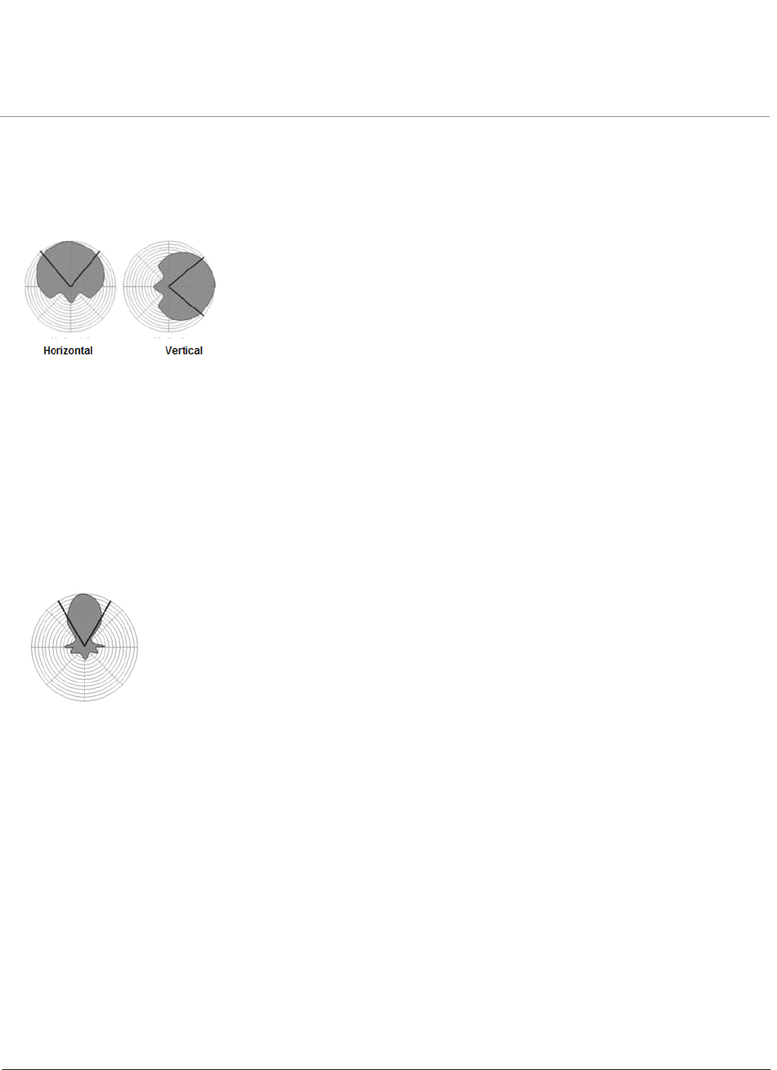
Sector Antennas
Sector antennas are high-gain directional antennas. These cylinders contain a boom supporting thin vertical rods. The
signal propagates off the front of the boom. Note that some signal (back lobes) fall behind the boom. Sector antennas
create higher gain by producing narrower beams (20 – 80 H, 14 – 64 V).
The wide-angle sector antenna is a good Base Station antenna for hilly terrain. It combines a wide opening angle “sector”
with relatively high gain. The mounting brackets allow tilting of the antenna. This antenna also is used when the amount
of traffic in a cell is too high for a single Base Station with an omni-directional antenna. The wide-angle antenna allows
dividing the cell into three sectors that each can be serviced by a Base Station.
Figure 1-3 Sector Antenna Coverage
Horizontal and Vertical

Introduction ORiNOCO Series System Recommended Antennas
Antenna Types
11
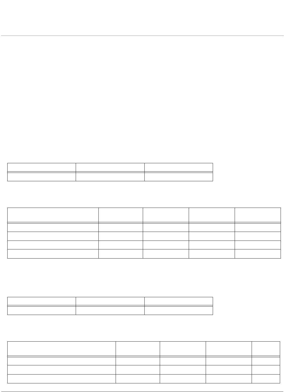
Parabolic Dish Antennas
Parabolic antennas are concave panels or bowls that produce an extremely narrow beam (4 – 25 degrees horizontal /
vertical).
Figure 1-4 Parabolic Dish Antenna Coverage
Summary
Omni Directional Antenna
An omni-directional antenna may be used in an outdoor environment to provide coverage to areas where it is not
practical to use an antenna system that takes advantage of sectorized coverage. As an example, if an area needing
coverage is a hillside and the base station is located on a valley floor, an omni-directional antenna could be a better
choice than a more traditional sector antenna such as a panel antenna. The omni-directional antenna would allow valley
floor coverage with coverage extending up a hillside. Such coverage is likely not possible with a panel antenna because
of the reduced radiation at high elevation angles from the antenna. This is a result of the shape of the antenna beam
radiating from the panel antenna design.
Flat Panel Directional Antenna
A flat panel antenna is frequently used for sectorized base station installations where it is desirable to provide coverage in
a limited azimuthal direction. This is useful in providing reduced interference from out of coverage areas and increasing
throughput by increased signal strength inside in coverage areas. Since a reduced azimuth area is covered, the radio
sees fewer subscribers and can provide increased bandwidth to each.
Sector
Sector antennas are better for corridors, hallways, tunnels, long narrow buildings, and point-to-point medium range
connections between outdoor bridges (for example, connecting two buildings in an office park or campus). Be wary of
back lobes, but the sector’s narrow beam will reduce unwanted peripheral exposure in the focal direction.
Parabolic
Parabolic antennas are better for long-range outdoor point-to-point connectors, such as bridges that are miles apart.
They require more precise installation to aim signal where you want it, but have the very high gain necessary to reach
such distances.
NOTE:
• All Proxim radios require professional installation.
• Antennas with gain less than 8 dBi are not allowed.
• Antennas of other makes can be used with the, but must be of the same type, dimensions, and gain as those listed.
Horizontal and Vertical
ORiNOCO Series System Recommended Antennas
12
2
Recommended 900 MHz Antennas and
Accessories
•Omni Antennas
•Sector Antennas
•Panel Antennas
Omni Antennas
The following 900 MHz omni antenna has been certified with the Tsunami 954-R BSU. See the manufacturer’s web site
for more information.
In addition, following 900 MHz omni antennas are available for use with the Tsunami 954-R BSU. See the
manufacturer’s web site for more information.
Sector Antennas
The following 900 MHz sector antenna has been certified with the Tsunami 954-R BSU. See the manufacturer’s web site
for more information.
In addition, following 900 MHz sector antennas are available for use with the Tsunami 954-R BSU. See the
manufacturer’s web site for more information.
Manufacturer Model Number Maximum Gain
Antel BCD-87010 12
Type Manufacturer Model Number Frequency
Range (MHz)
Mid-Band Gain
Vertical polarization omni antenna Mars MA-W091-8X 902-928 8
Vertical polarization omni antenna MTI MT-262003/NV 902-928 8
Horizon polarization omni antenna MTI MT-262012/NH 902-928 10.5
Horizon polarization omni antenna MTI MT-243003/NH 902-928 11.5
Manufacturer Model Number Maximum Gain
Antel RWA-80017 19
Type Manufacturer Model Number Frequency
Range (MHz)
Mid-Band
Gain
Vertical polarization 60° sector antenna Mars MA-WC90-5X 902-928 14.5
Horizon polarization 60° sector antenna Mars MA-WC91-5H 902-928 14
Vertical polarization 90° sector antenna Mars MA-WD90-6X 902-928 13
Recommended 900 MHz Antennas and Accessories ORiNOCO Series System Recommended Antennas
Panel Antennas
13
Panel Antennas
The following 900 MHz panel antenna has been certified with the Tsunami 954-R SU. See the manufacturer’s web site for
more information.
In addition, following 900 MHz panel antennas are available for use with the Tsunami 954-R SU. See the manufacturer’s
web site for more information.
Cavity Filters
900 MHz outdoor cavity filters provide a high-performance filtering solution by offer ing low insertion loss and great
rejection characteristics; they are capable of blocking out interference at the 900 MHz ISM band edges (902 MHz and
928 MHz). This is especially crucial when colocating 954-R equipment in urban or omni deployments in the presence of
strong interferers operating at these frequencies.
The following cavity filters are available for use with the 954-R. See the manufacturer’s web site for more information.
Horizon polarization 90° sector antenna Mars MA-WD91-6H 902-928 12
Vertical polarization 120° sector antenna Mars MA-WE90-7X 902-928 11.5
Horizon polarization 120° sector antenna Mars MA-WE91-7H 902-928 11
Dual polarization 120° sector antenna Mars MA-WE91-2D 902-928 11.5
Horizon polarization 90° sector antenna MTI MT-264003/NH 902-928 13.5
Horizon polarization 120° sector antenna MTI MT-263004/NH 902-928 12.5
Horizon polarization 180° sector antenna MTI MT-243015/NH 902-928 10
Manufacturer Model Number Maximum Gain
MTI MT-263006 12.5
Type Manufacturer Model Number Frequency Range (MHz) Mid-Band Gain
1-foot panel antenna ARC wireless ANT-A-1714 902-928 10
1-foot panel antenna Mars MA-IS91 902-928 10
1-foot panel antenna MTI MT-262001 902-928 8
1-foot panel antenna MTI MT-263003 902-928 10
Type Manufacturer Model Number
912 MHz (Center Frequency) Cavity Filter Ubiquiti CF912
917 MHz (Center Frequency) Cavity Filter Ubiquiti CF917
Type Manufacturer Model Number Frequency
Range (MHz)
Mid-Band
Gain
ORiNOCO Series System Recommended Antennas
14
3
Recommended 2.4 GHz Antennas
•Omni Antennas
•Sector Antennas
•Panel Antennas
•Parabolic Antennas
Omni Antennas
•5 dBi Omni-Directional Vehicle Antenna (848 515 722)
•7 dBi Omni-Directional Base Station Antenna (848 312 591)
•10 dBi Omni-Directional Base Station Antenna (848 515 698)
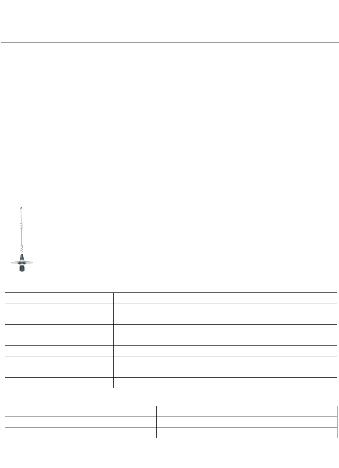
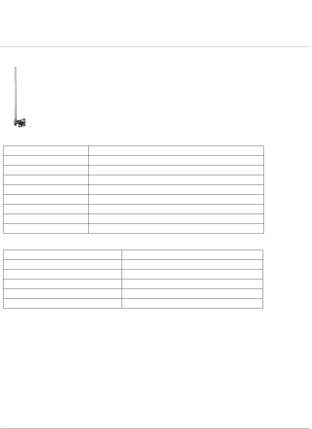
5 dBi Omni-Directional Vehicle Antenna (848 515 722)
Electrical Specifications
Environmental and Mechanical Specifications
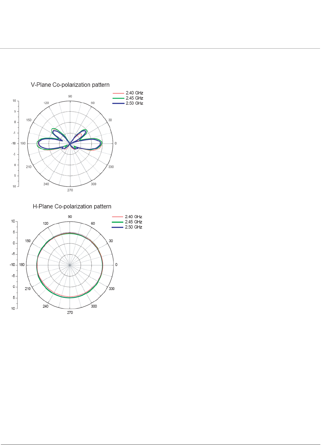
Frequency Range 2400 MHz to 2500 MHz
VSWR Less than 2:1
Nominal Impedance 50 Ohms
Gain 5 dBi
Polarization Linear, Vertical
HPBW/Horizontal 360°
HPBW/Vertical 25°
Power Handling 10 W (cw)
Connector Type N Jack
Temperature Range -10 to +55 °C
Size 80 x 80 x 250 mm
Cable Color White
Recommended 2.4 GHz Antennas ORiNOCO Series System Recommended Antennas
Omni Antennas
15
5 dBi Omni-Directional Antenna (848 515 722) (continued)
Antenna Patterns
Recommended 2.4 GHz Antennas ORiNOCO Series System Recommended Antennas
Omni Antennas
16
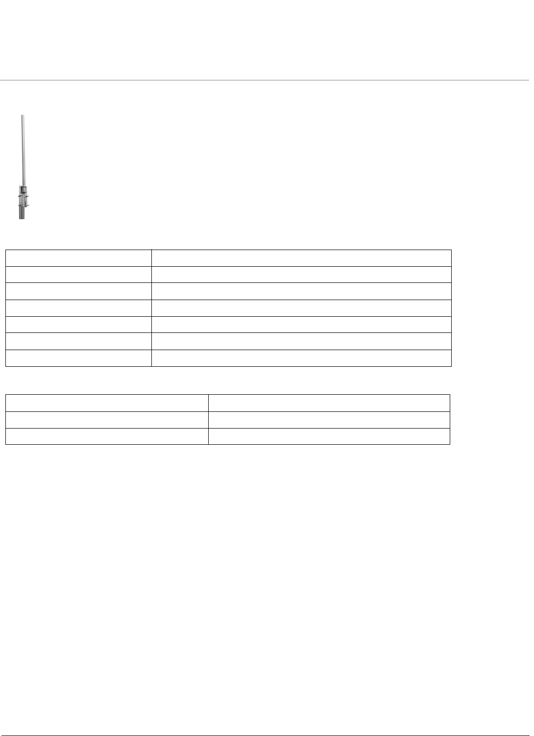
7 dBi Omni-Directional Base Station Antenna (848 312 591)
Electrical Specifications
Environmental and Mechanical Specifications
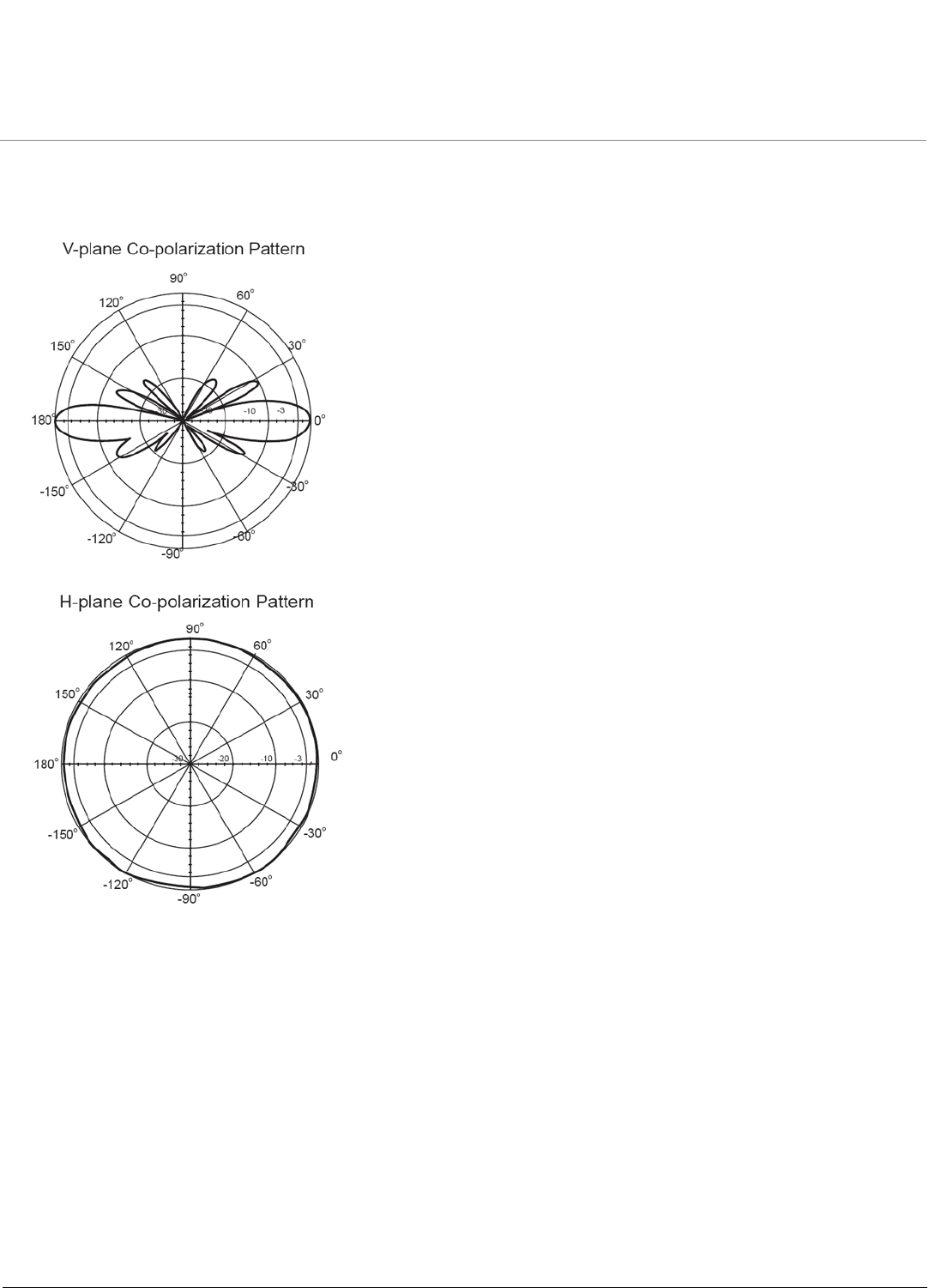
Frequency Range 2400 MHz –2500 MHz
VSWR Less than 2:1
Nominal Impedance 50 Ohms
Gain 8 dBi
Polarization Linear, Vertical
HPBW/Horizontal 360°
HPBW/Vertical 15°
Handling 10 W
Connector Type Standard N Female
Wind Survival 216 km/hr
Temperature Range -40 to +80 °C
Humidity 95% @ 25 °C
Size 19 x 19 x 520 mm
Color Gray-White
Weight .34 kg
Recommended 2.4 GHz Antennas ORiNOCO Series System Recommended Antennas
Omni Antennas
17
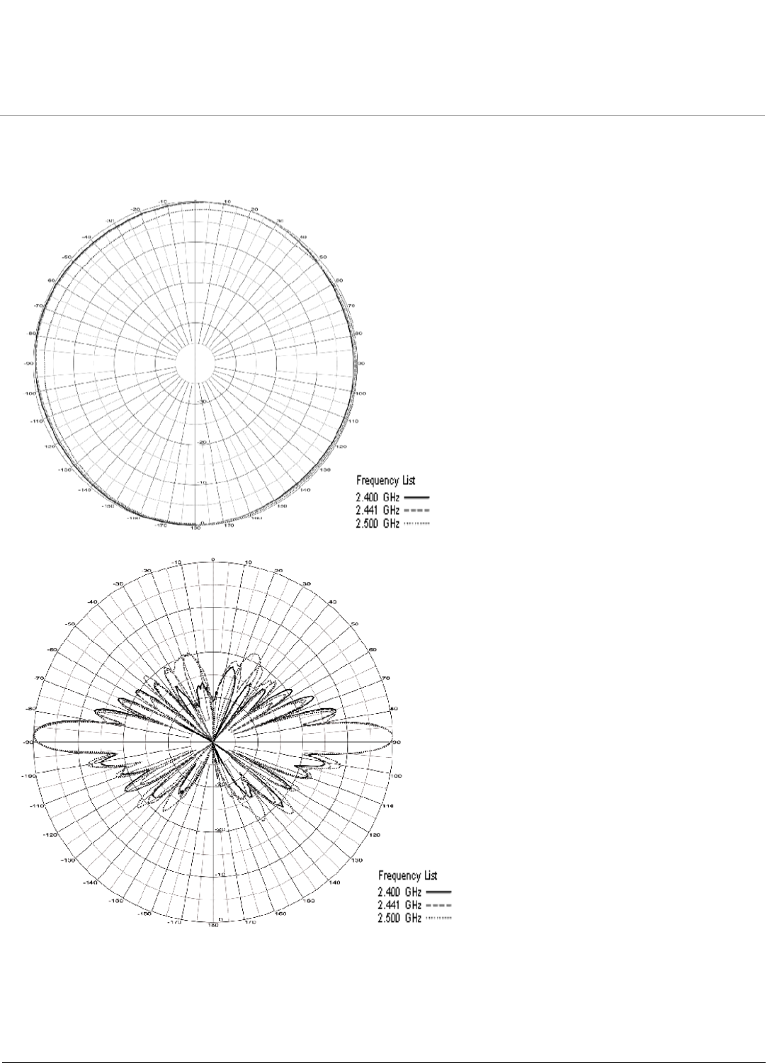
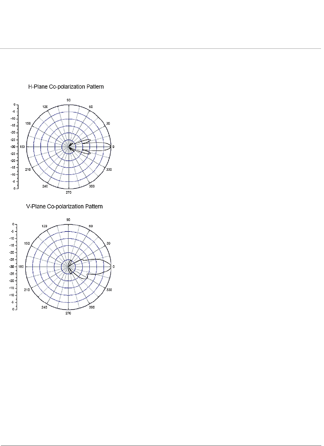
7 dBi Omni-Directional Base Station Antenna (848 312 591) (continued)
Antenna Patterns
Recommended 2.4 GHz Antennas ORiNOCO Series System Recommended Antennas
Omni Antennas
18
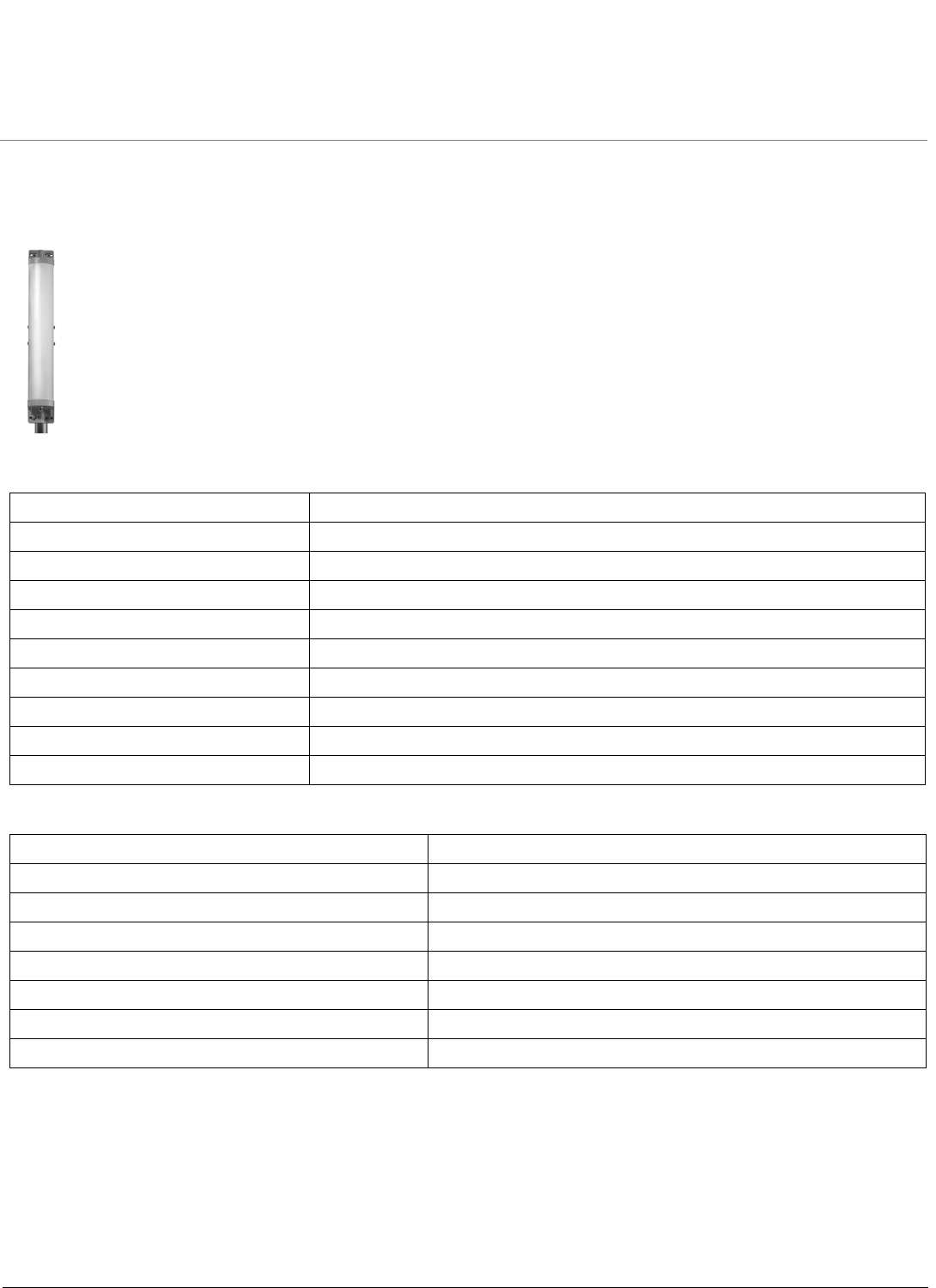
10 dBi Omni-Directional Base Station Antenna (848 515 698)
Electrical Specifications
Environmental and Mechanical Specifications
Frequency Range 2400 - 2500 MHz
VSWR Less than 2:1 nominal
Nominal Impedance 50 Ohms
Gain 10 dBi
Polarization Linear, Vertical
Connector Type Standard N Female
Power Handling 10 W
Wind Survival At least 240 km/hr with 1.25 cm ice
Temperature Range -40 to +60 °C
Size 91.4 cm
Recommended 2.4 GHz Antennas ORiNOCO Series System Recommended Antennas
Omni Antennas
19
10 dBi Omni-Directional Base Station Antenna (848 515 698) (continued)
Antenna Patterns
Recommended 2.4 GHz Antennas ORiNOCO Series System Recommended Antennas
Sector Antennas
20
Sector Antennas
•12 dBi Directional Wide Angle Antenna (120°) (848 515 706)
•14 dBi Sector Antenna (60°) (2400-SA60-14)
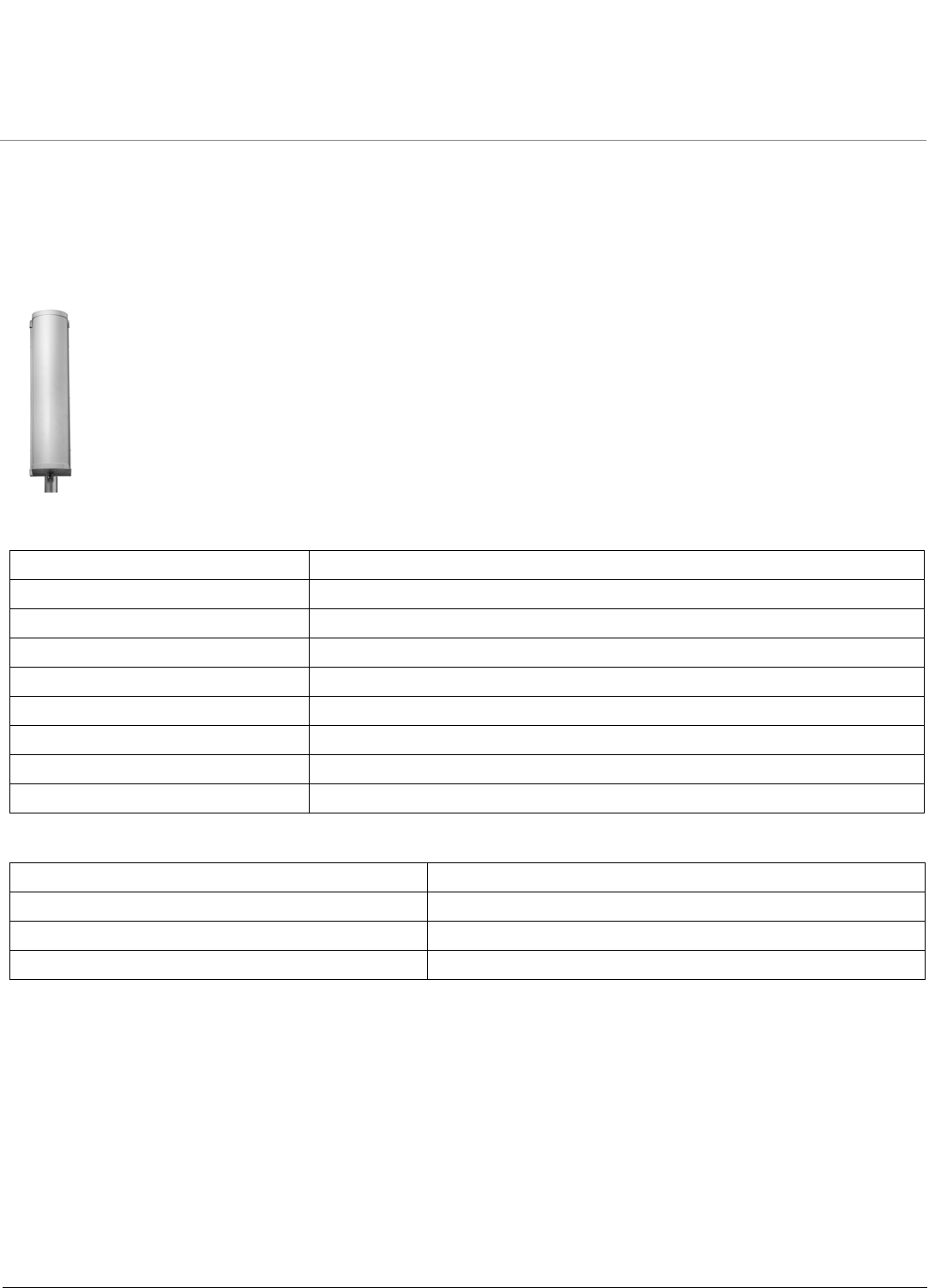
12 dBi Directional Wide Angle Antenna (120°) (848 515 706)
Electrical Specifications
Environmental and Mechanical Specifications
Frequency Range 2400 MHz to 2500 MHz
VSWR Less than 2 : 1 nominal
Nominal Impedance 50 Ohms
Gain 12 dBi
Polarization Linear, Vertical
Connector Type Standard N Female
HPBW/Horizontal 125°
HPBW/Vertical 13°
Power Handling 10 W
Wind Survival 200 km/hr
Temperature Range -40 to +60 °C
Humidity 100% at 25 °C
Size 181 x 537 x76 mm
Recommended 2.4 GHz Antennas ORiNOCO Series System Recommended Antennas
Sector Antennas
21
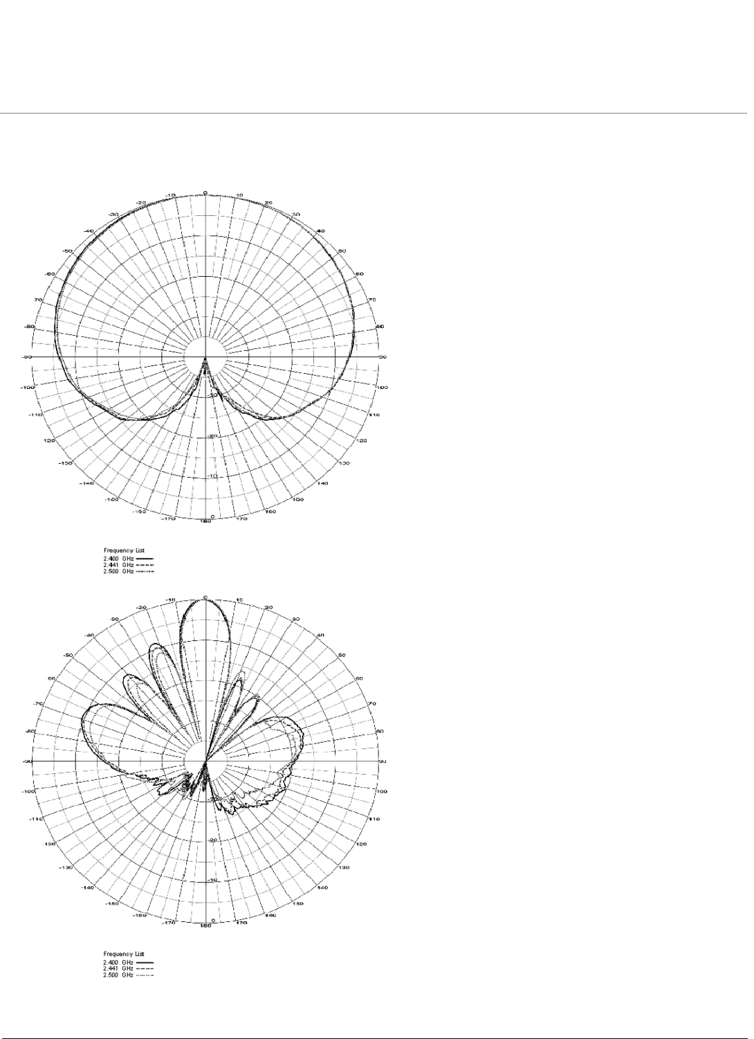
12 dBi Directional Wide Angle Antenna (120°) (848 515 706) (continued)
Antenna Patterns
Azimuth Plane (Horizontal)
Elevation Plane (Vertical)
Recommended 2.4 GHz Antennas ORiNOCO Series System Recommended Antennas
Sector Antennas
22
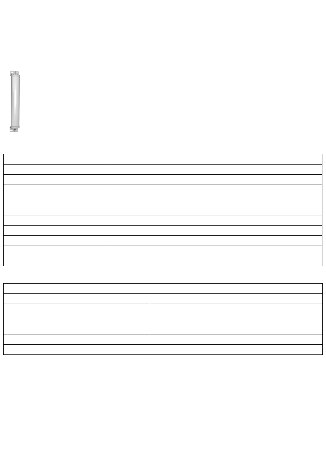
14 dBi Sector Antenna (60°) (2400-SA60-14)
Electrical Specifications
Environmental and Mechanical Specifications
Frequency Range 2400 MHz to 2500 MHz
VSWR 1.8 : 1 maximum
Nominal Impedance 50 Ohms
Gain 14 dBi
Polarization Linear, Vertical
Connector Type N Jack
Power Handling 5 W (cw)
HPBW/Horizontal 65°
HPBW/Vertical 13°
Front to Back Ratio 25 dB
Downtilt 0°
Wind Survival 216 km/hr
Temperature range -40 to +80 °C
Humidity 100% at 25 °C
Size 620 x 88 x 70 mm
Radome Color Gray-White
Radome Material ABS, UV Resistant
Weight 5.55 kg
Recommended 2.4 GHz Antennas ORiNOCO Series System Recommended Antennas
Sector Antennas
23
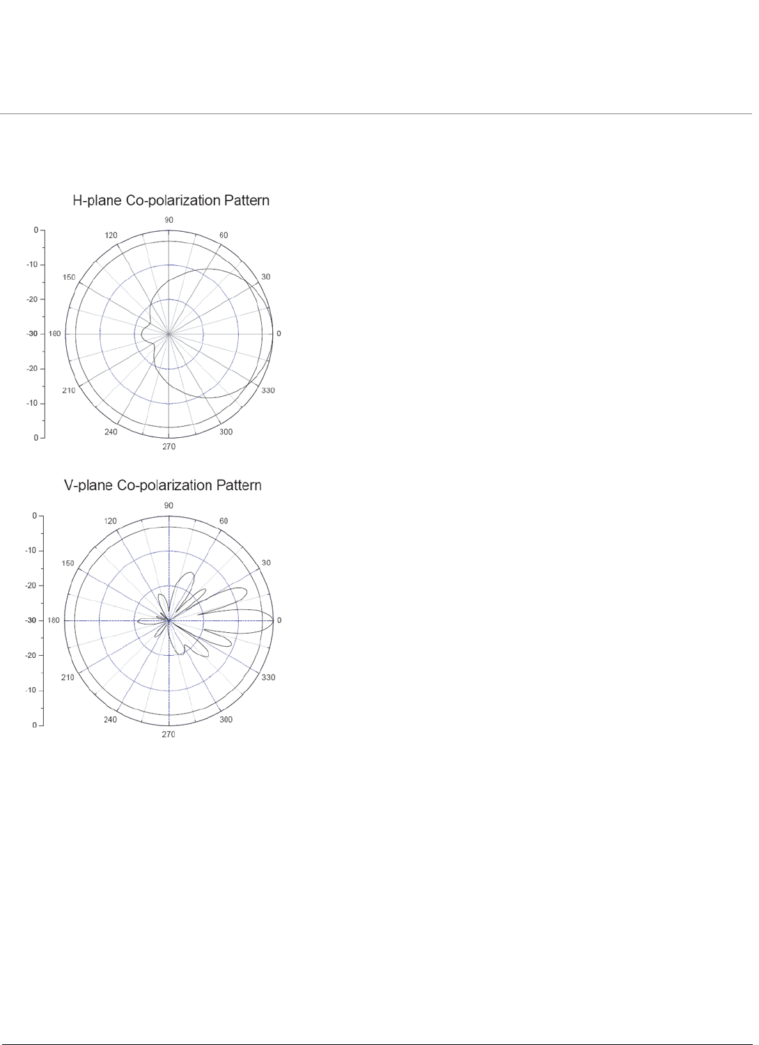
14 dBi Sector Antenna (60°) (2400-SA60-14) (continued)
Antenna Patterns
Recommended 2.4 GHz Antennas ORiNOCO Series System Recommended Antennas
Panel Antennas
24
Panel Antennas
•14 dBi Directional Panel Antenna (1086-PA24-14)
•Parabolic Antennas
14 dBi Directional Panel Antenna (1086-PA24-14)
Electrical Specifications
Environmental and Mechanical Specifications
Frequency Range 2400 MHz - 2500 MHz
VSWR 1.5 : 1 maximum
Nominal Impedance 50 Ohms
Gain 14 dBi
Polarization Linear, Vertical
Connector Type Standard N Female
HPBW/Horizontal 30°
HPBW/Vertical 30°
Front to Back Ratio 15 dB
Downtilt 0°
Power Handling 50 W (cw)
Wind Survival 216 km/hr
Temperature Range -40 to +80 °C
Humidity 95% at 25 °C
Lightning Protection DC Ground
Radome Color Gray-White
Radome Material ABS
Weight 407 g
Size 200 x 200 x 50 mm
Recommended 2.4 GHz Antennas ORiNOCO Series System Recommended Antennas
Panel Antennas
25
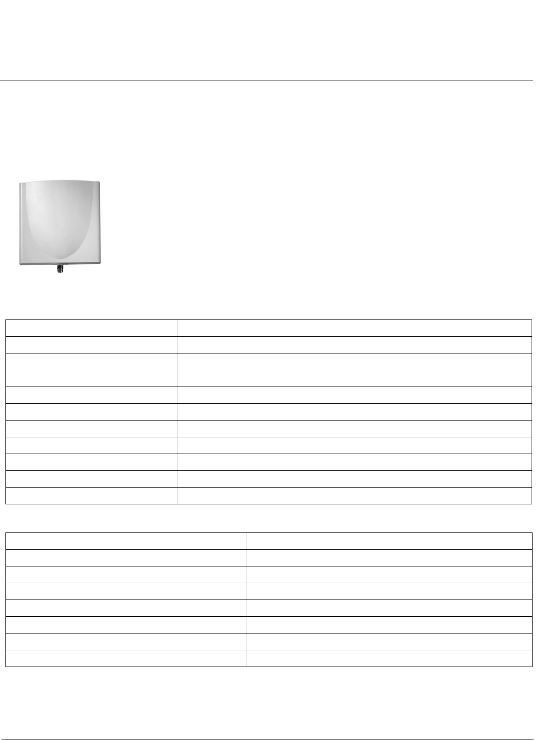
14 dBi Directional Panel Antenna (1086-PA24-14) (continued)
Antenna Patterns
Recommended 2.4 GHz Antennas ORiNOCO Series System Recommended Antennas
Parabolic Antennas
26
Parabolic Antennas
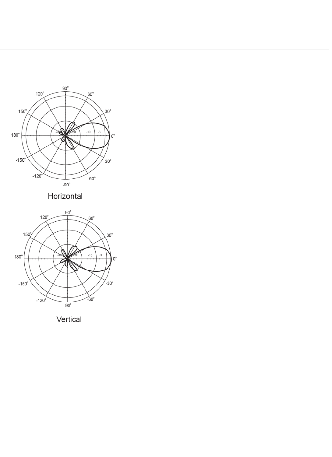
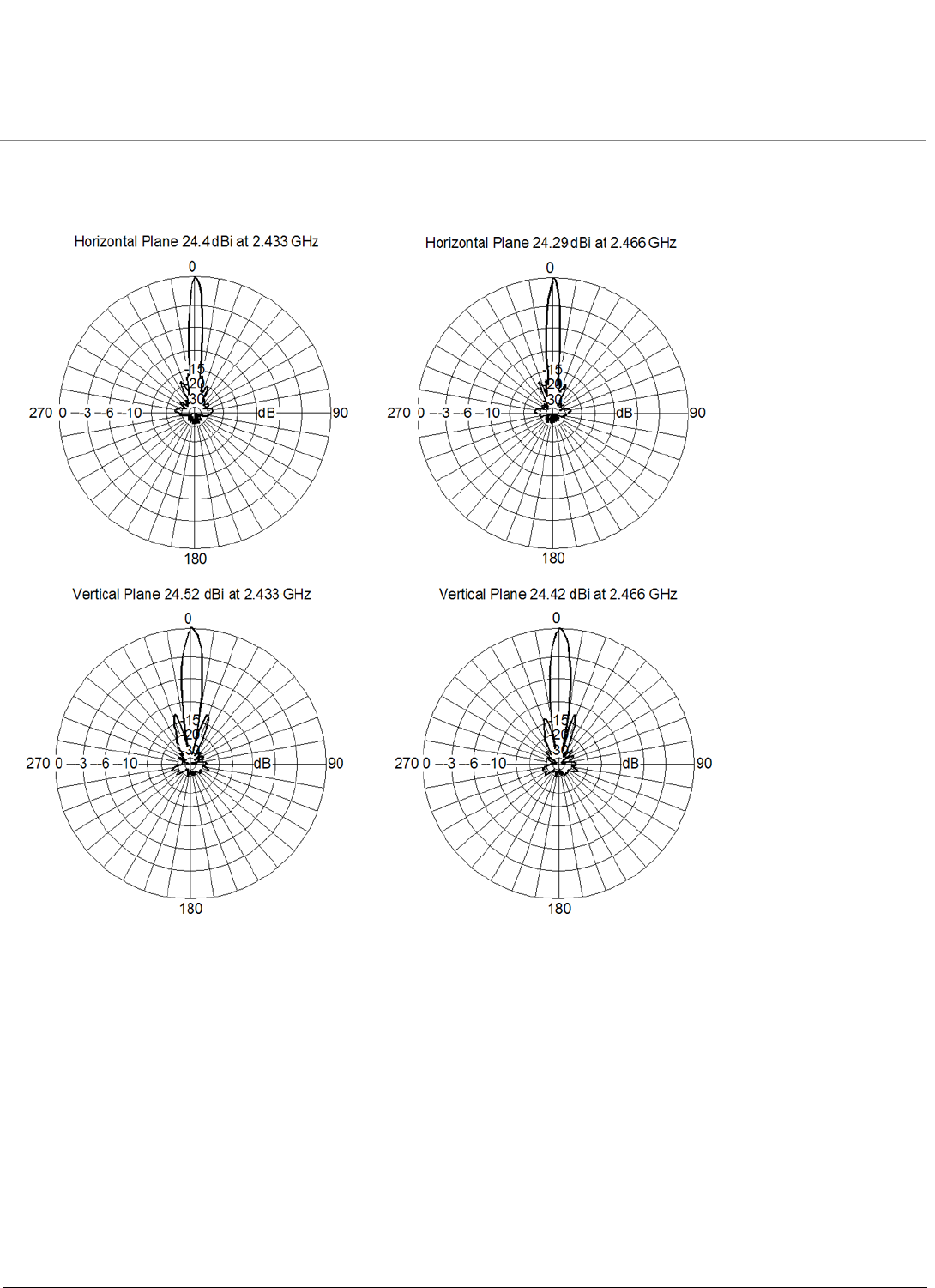
24 dBi Directional Parabolic Grid Antenna (848 515 714)
Electrical Specifications
Environmental and Mechanical Specifications
Frequency Range 2400 MHz - 2484 MHz
VSWR Less than 2 : 1 nominal
Nominal Impedance 50 Ohms
Gain 24 dBi
Polarization Linear, vertical for standard mounting
Horizontal when mounted differently
HPBW/Horizontal 6.5°
HPBW/Vertical 10°
Connector Type Standard N, Female
Power Handling 50 W
Wind Survival At least 200 km/h
Temperature Range -40 to +60 °C
Color White
Weight 0.6 kg
Size 610 x 914 x 381 cm
Recommended 2.4 GHz Antennas ORiNOCO Series System Recommended Antennas
Parabolic Antennas
27
24 dBi Directional Parabolic Grid Antenna (848 515 714) (continued)
Antenna Patterns
ORiNOCO Series System Recommended Antennas
28
4
Recommended 4.9 GHz Antennas
•Omni Antennas
•Sector Antennas
Omni Antennas
•8 dBi Omni-Directional Antenna (1086-OA49-8)
•10 dBi Omni-Directional Antenna (1086-OA49-10)
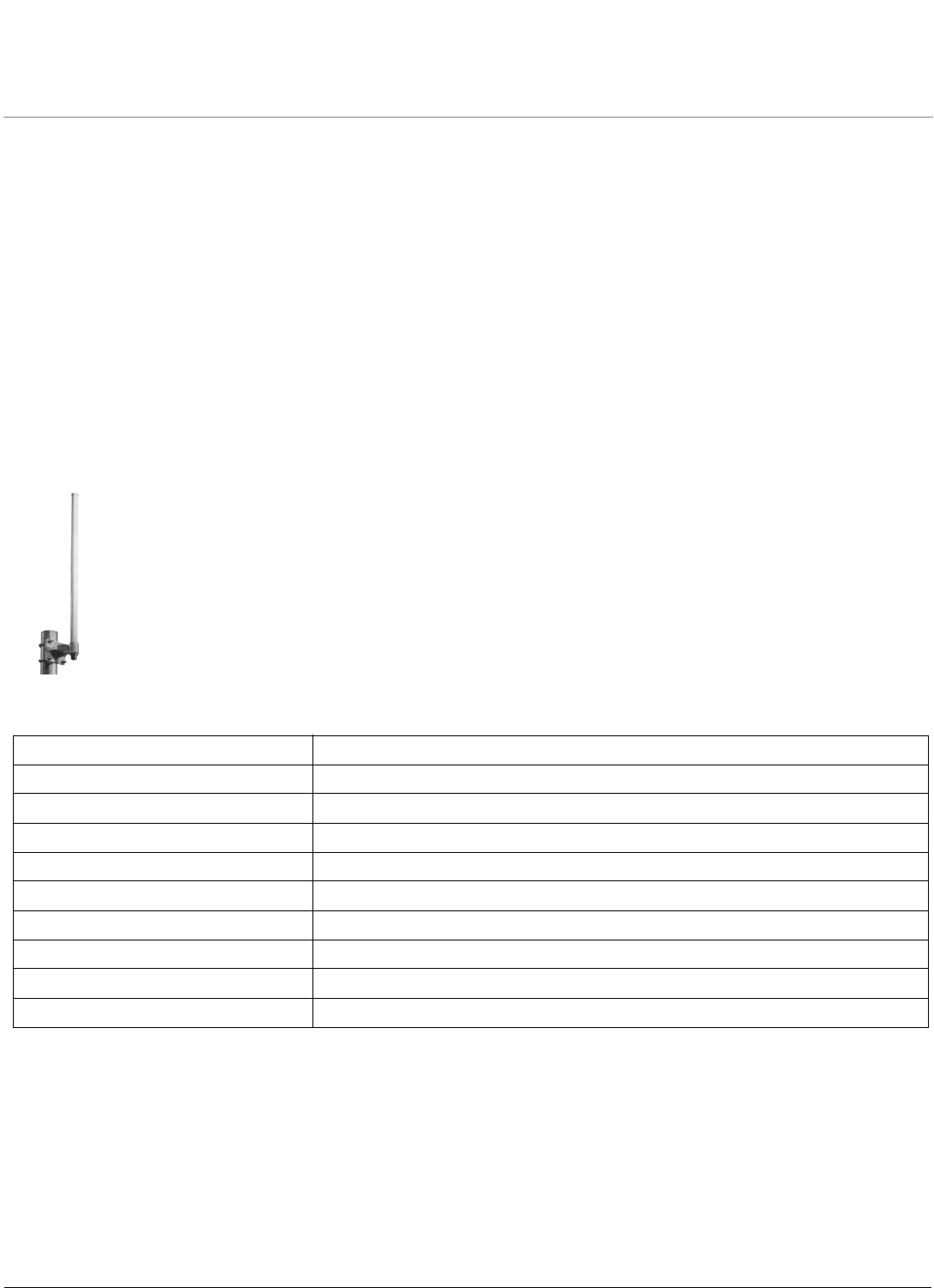
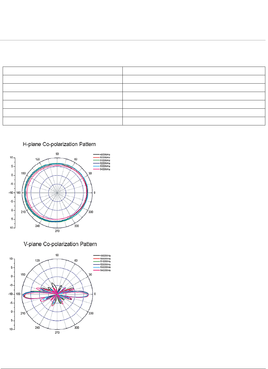
8 dBi Omni-Directional Antenna (1086-OA49-8)
Electrical Specifications
Frequency Range 4900 MHz - 5200 MHz
VSWR 2.0 : 1 maximum
Nominal Impedance 50 Ohms
Gain 8 dBi
Polarization Linear, Vertical
Connector Type N-type Jack
HPBW/Horizontal 360°
HPBW/Vertical 12°
Downtilt 0°
Power Handling 5 W (cw)
Recommended 4.9 GHz Antennas ORiNOCO Series System Recommended Antennas
Omni Antennas
29
8 dBi Omni-Directional Antenna (1086-OA49-8) (continued)
Environmental and Mechanical Specifications
Antenna Patterns
Wind Survival 216 km/hr
Temperature Range -40 to +80 °C
Humidity 95% at 25 °C
Size 80 x 78 x 373 mm
Radome Color Gray-White
Radome Material Fiber Glass
Weight 227 g
Recommended 4.9 GHz Antennas ORiNOCO Series System Recommended Antennas
Omni Antennas
30
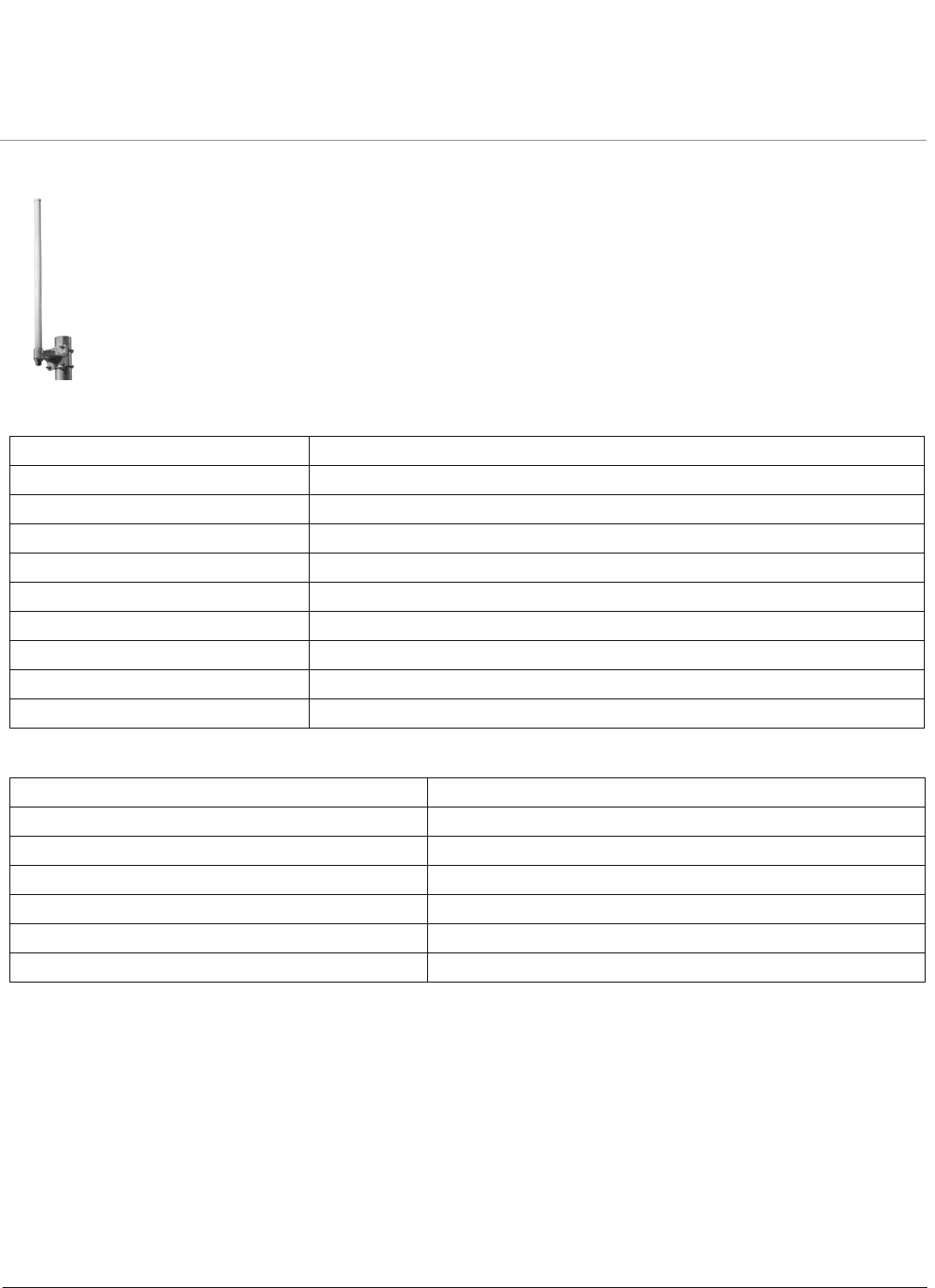
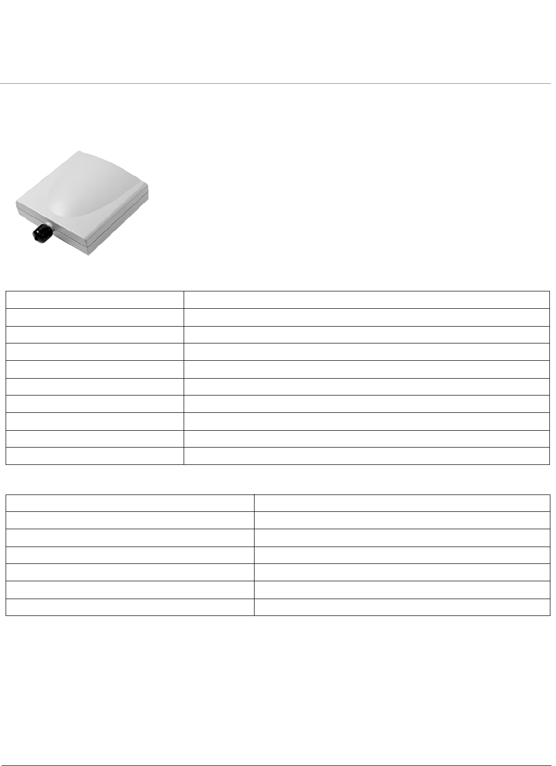
10 dBi Omni-Directional Antenna (1086-OA49-10)
Electrical Specifications
Environmental and Mechanical Specifications
Frequency Range 4900 MHz - 5000 MHz
VSWR 1.7 : 1 maximum
Nominal Impedance 50 Ohms
Gain 10 dBi
Polarization Linear, Vertical
Connector Type N-type Jack
HPBW/Horizontal 360°
HPBW/Vertical 7°
Downtilt 2°
Power Handling 5 W (cw)
Wind Survival 216 km/hr
Temperature Range -40 to +80 °C
Humidity 95% at 25 °C
Size 80 x 78 x 511 mm
Radome Color Gray-White
Radome Material Fiber Glass, UV Resistant
Weight 265 g
Recommended 4.9 GHz Antennas ORiNOCO Series System Recommended Antennas
Omni Antennas
31
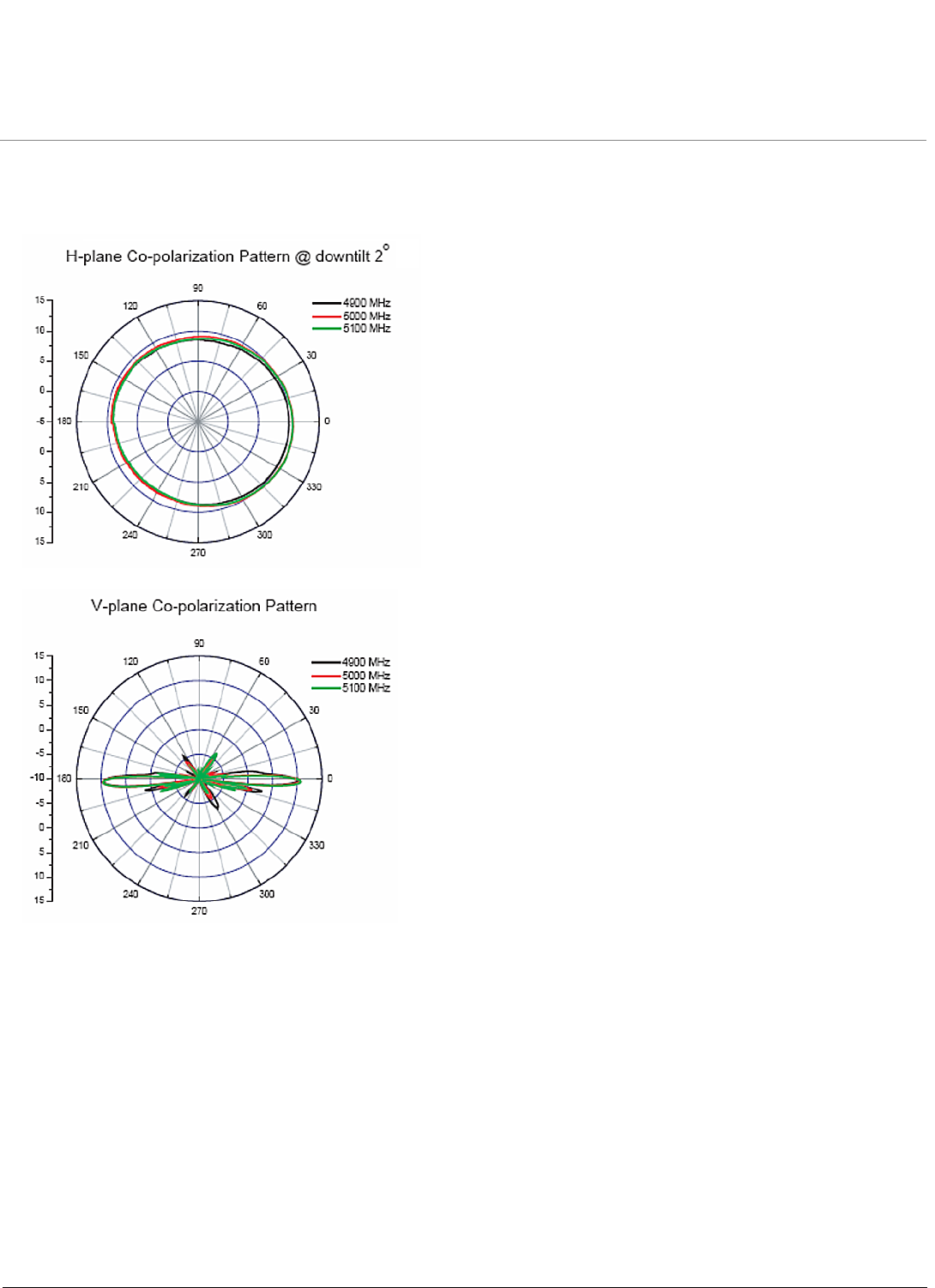
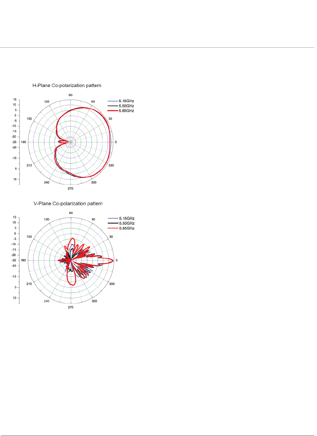
10 dBi Omni-Directional Antenna (1086-OA49-10) (continued)
Antenna Patterns
Recommended 4.9 GHz Antennas ORiNOCO Series System Recommended Antennas
Panel Antennas
32
Panel Antennas
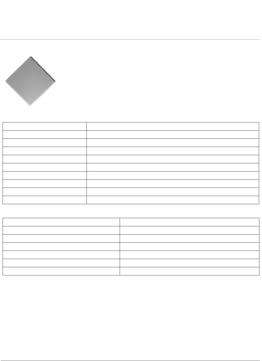
10 dBi Panel Antenna (1086-PA49-10)
Electrical Specifications
Environmental and Mechanical Specifications
Frequency Range 4900 MHz - 5800 MHz
VSWR 2.0 : 1 maximum
Nominal Impedance 50 Ohms
Gain 10 dBi
Polarization Linear, Vertical
Connector Type N-type Jack
HPBW/Horizontal 45°
HPBW/Vertical 45°
Downtilt 0°
Power Handling 2 W (cw)
Wind Survival 216 km/hr
Temperature Range -40 to +80 °C
Humidity 95% at 25 °C
Size 114 x 114 x 40 mm
Radome Color Light Gray
Radome Material ABS
Weight 107 g
Recommended 4.9 GHz Antennas ORiNOCO Series System Recommended Antennas
Panel Antennas
33
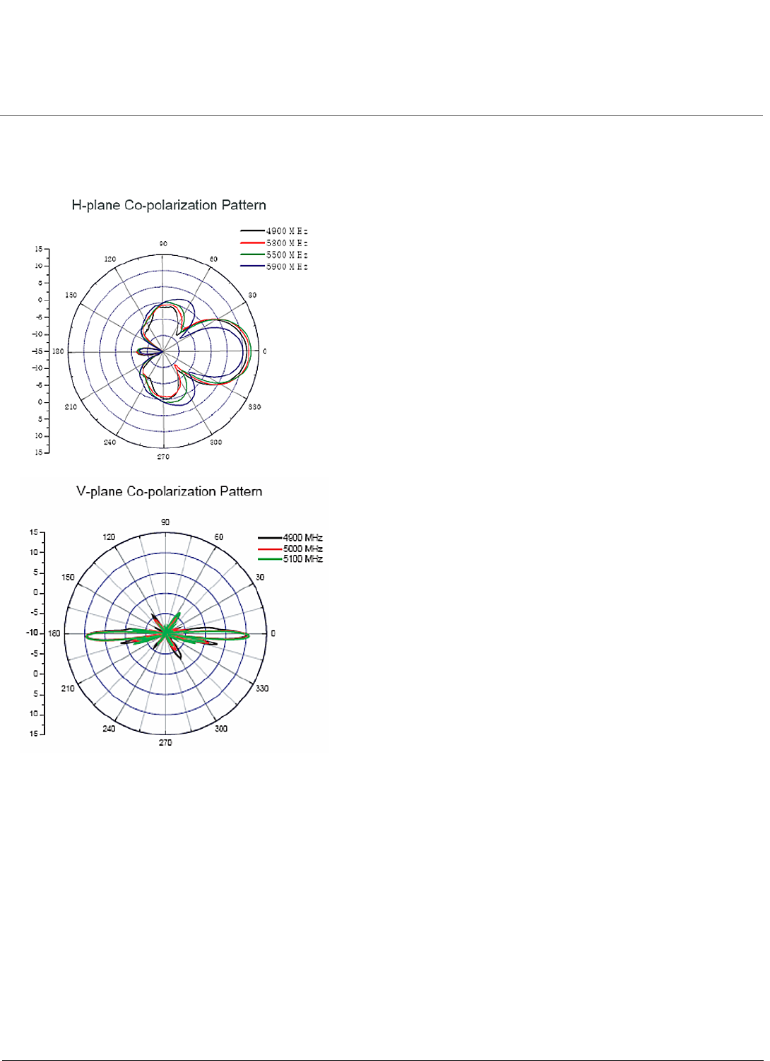
10 dBi Panel Antenna (1086-PA49-10) (continued)
Antenna Patterns
Recommended 4.9 GHz Antennas ORiNOCO Series System Recommended Antennas
Panel Antennas
34
21 dBi Panel Antenna (1086-PA49-21)
Electrical Specifications
Environmental and Mechanical Specifications
Frequency Range 4900 MHz - 5000 MHz
VSWR 1.7 : 1 maximum
Nominal Impedance 50 Ohms
Gain 21 dBi
Polarization Linear, Vertical
Connector Type N-type Jack
HPBW/Horizontal 10°
HPBW/Vertical 12°
Front to Back Ratio 30°
Power Handling 1 W (cw)
Wind Survival 216 km/hr
Temperature Range -40 to +80 °C
Humidity 95% at 25 °C
Size 320 x 320 x 18 mm
Radome Color Gray-White
Radome Material PC, UV Resistant
Weight 1.2 kg
Recommended 4.9 GHz Antennas ORiNOCO Series System Recommended Antennas
Panel Antennas
35
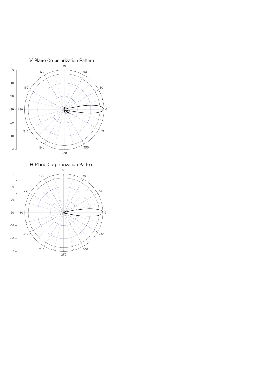
21 dBi Panel Antenna (1086-PA49-21) (continued)
Antenna Patterns
Recommended 4.9 GHz Antennas ORiNOCO Series System Recommended Antennas
Sector Antennas
36
Sector Antennas
14 dBi Sector Antenna (120°) (5054-SA120-14)
Electrical Specifications
Environmental and Mechanical Specifications
Frequency Range 4945 MHz - 5875 MHz
VSWR 2.0 : 1 maximum
Nominal Impedance 50 Ohms
Gain 12.5 dBi (max)
Polarization Linear, Vertical
Connector Type N-type Female
HPBW/Horizontal 120°
HPBW/Vertical 6°
Front to Back Ratio 30°
Downtilt 0°
Wind Survival (per EIA-222-F at 100’ height) 216 km/hr
Temperature Range -40 to +80 °C
Humidity 95% at 25 °C
Lightning Protection DC Ground
Size 620 x 88 x 70 mm
Radome Color Gray
Radome Material ABS
Weight 555 g
Recommended 4.9 GHz Antennas ORiNOCO Series System Recommended Antennas
Sector Antennas
37
14 dBi Sector Antenna (120°) (5054-SA120-14) (continued)
Antenna Patterns
Recommended 4.9 GHz Antennas ORiNOCO Series System Recommended Antennas
Sector Antennas
38
17 dBi Sector Antenna (60°) (5054-SA60-17)
Electrical Specifications
Environmental and Mechanical Specifications
Frequency Range 4945 MHz - 5875 MHz
VSWR 2.0 : 1 maximum
Nominal Impedance 50 Ohms
Gain 16.5 dBi
Polarization Linear, Vertical
Connector Type N-type Female
HPBW/Horizontal 60°
HPBW/Vertical 6°
Power Handling 5 W (cw)
Downtilt 0°
Wind Survival (per EIA-222-F at 100’ height) 216 km/hr
Temperature Range -40 to +90 °C
Humidity 95% at 25 °C
Lightning Protection DC Ground
Size 620 x 88 x 70 mm
Radome Color Gray
Radome Material ABS
Weight 565 g
Recommended 4.9 GHz Antennas ORiNOCO Series System Recommended Antennas
Sector Antennas
39
17 dBi Sector Antenna (60°) (5054-SA60-17) (continued)
Antenna Patterns
ORiNOCO Series System Recommended Antennas
40
5
Recommended 5 GHz Antennas
•Omni-Directional Antennas
•Sector Antennas
•Panel Antennas
•Parabolic Antennas
Omni-Directional Antennas
•8 dBi Omni-Directional Antenna (5054-OA-8)
•10 dBi Omni-Directional Antenna (5054-OA-10)
•Other Recommended Omni-Antennas
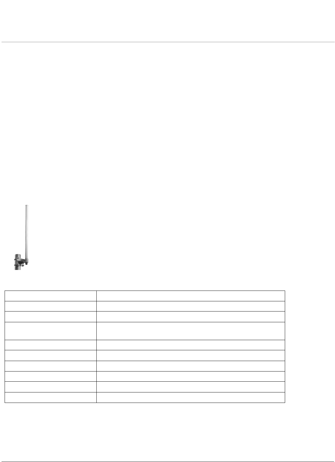
8 dBi Omni-Directional Antenna (5054-OA-8)
Electrical Specifications
Frequency Range 5470 MHz – 5875 MHz
VSWR 2.0 : 1 maximum
Nominal Impedance 50 Ohms
Average/Peak Gain 7.8/9.0 dBi @ 5.5 GHz
8.1/9.4 dBi @ 5.7 GHz
HPBW/Horizontal 360°
HPBW/Vertical 12°
Polarization Linear, Vertical
Electrical Downtilt 0°
Power Handling 5 W (cw)
Connector Type Standard N Female
Recommended 5 GHz Antennas ORiNOCO Series System Recommended Antennas
Omni-Directional Antennas
41
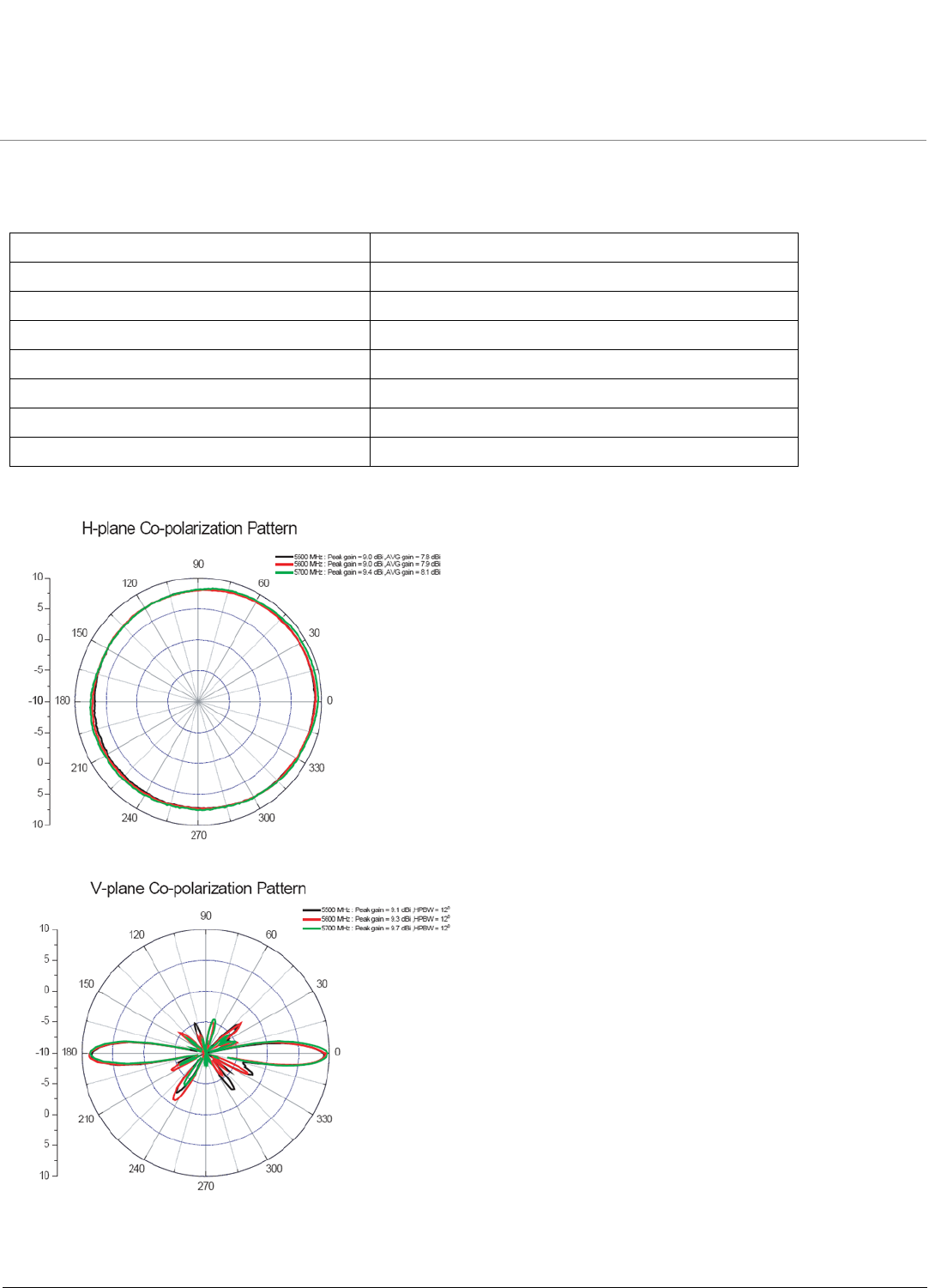
8 dBi Omni-Directional Antenna (5054-OA-8) (continued)
Environmental and Mechanical Specifications
Antenna Patterns
Wind Survival 216 km/hr
Temperature Range -40 to +90 °C
Humidity 95% @ 25 °C
Lightning Protection DC ground
Size 78 x 80 x 373 mm
Radome Color Gray-White
Radome Material Fiberglass
Weight 245 g
Recommended 5 GHz Antennas ORiNOCO Series System Recommended Antennas
Omni-Directional Antennas
42
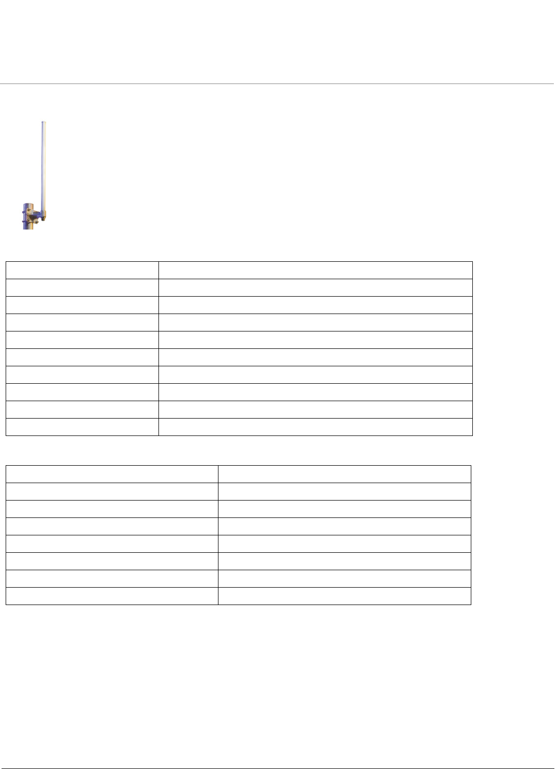
10 dBi Omni-Directional Antenna (5054-OA-10)
Electrical Specifications
Environmental and Mechanical Specifications
Frequency Range 5470 MHz – 5875 MHz
VSWR 2.0 : 1 maximum
Nominal Impedance 50 Ohms
Gain 10 dBi
HPBW/Horizontal 360°
HPBW/Vertical 7°
Polarization Linear, Vertical
Downtilt 2°
Power Handling 5 W (cw)
Connector Type Standard N Female
Wind Survival (per EIA-222-F at 100’ height) 216 km/hr
Temperature Range -40 to +80 °C
Humidity 95% @ 25 °C
Lightning Protection DC ground
Size 78 x 80 x 511 mm
Radome Color Gray-White
Radome Material Fiberglass
Weight 265 g
Recommended 5 GHz Antennas ORiNOCO Series System Recommended Antennas
Omni-Directional Antennas
43
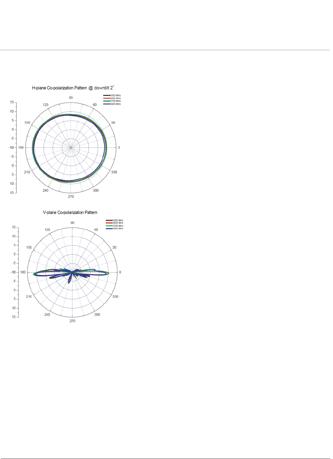
10 dBi Omni-Directional Antenna (5054-OA-10) (continued)
Antenna Patterns

Recommended 5 GHz Antennas ORiNOCO Series System Recommended Antennas
Omni-Directional Antennas
44
Other Recommended Omni-Antennas
Manufacturer Model Number Frequency Range Mid-Band Gain
Mars MA-WO58-9X 5.47 – 5.875 9
MTI MT-482003/N 5.15 – 5.875 9
MTI MT-482009/N 5.725-5.875 12
MTI MT-483003/N 5.725-5.875 12
Stella Doradus 52 1360 5.1-5.3 7
Stella Doradus 52 2360 5.1-5.3 10
Stella Doradus 52 3360 5.1-5.3 13
Stella Doradus 58 1360 5.7-5.8 7
Stella Doradus 58 2360 5.7-5.8 10
Stella Doradus 58 3360 5.7-5.8 13
Telex 5830 5.725-5.85 7.5
Radio Waves OMN-H-5-8 5.725-5.85 8 (hor pol)
Recommended 5 GHz Antennas ORiNOCO Series System Recommended Antennas
Sector Antennas
45
Sector Antennas
•14 dBi Sector Antenna (120°) (5054-SA120-14)
•17 dBi Sector Antenna (60°) (5054-SA60-17)
•Other Recommended Sector Antennas
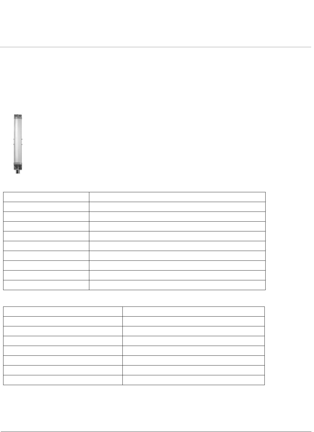
14 dBi Sector Antenna (120°) (5054-SA120-14)
Electrical Specifications
Environmental and Mechanical Specifications
Frequency Range 5150 MHz – 5875 MHz
VSWR 2.0 : 1 maximum
Nominal Impedance 50 Ohms
Gain 13.5 dBi
HPBW/Horizontal 120°
HPBW/Vertical 6°
Polarization Linear, Vertical
Downtilt 0°
Power Handling 5 W (cw)
Connector Type Standard N Female
Wind Survival 216 km/hr
Temperature Range -40 to +80 °C
Humidity 95% @ 25 °C
Lightning Protection DC Ground
Size 620 x 80 x 70 mm
Radome Color Gray
Radome Material ABS
Weight 555 g

Recommended 5 GHz Antennas ORiNOCO Series System Recommended Antennas
Sector Antennas
46
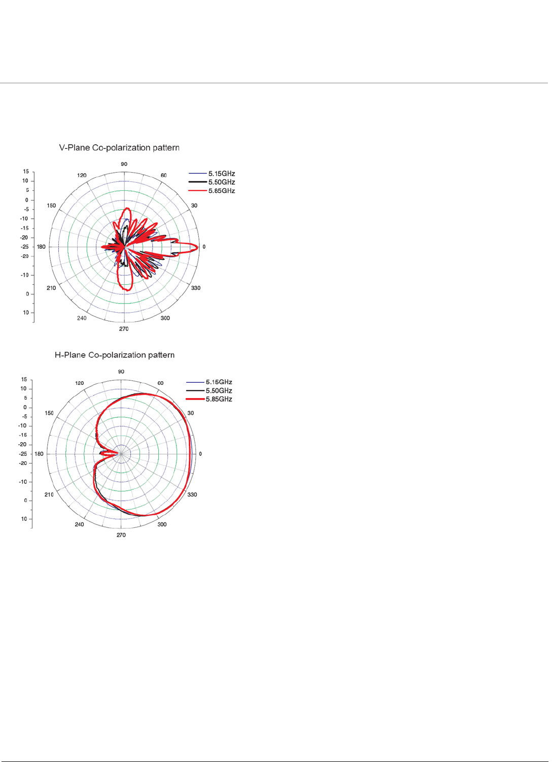
14 dBi Sector Antenna (120°) (5054-SA120-14) (continued)
Antenna Patterns
Recommended 5 GHz Antennas ORiNOCO Series System Recommended Antennas
Sector Antennas
47
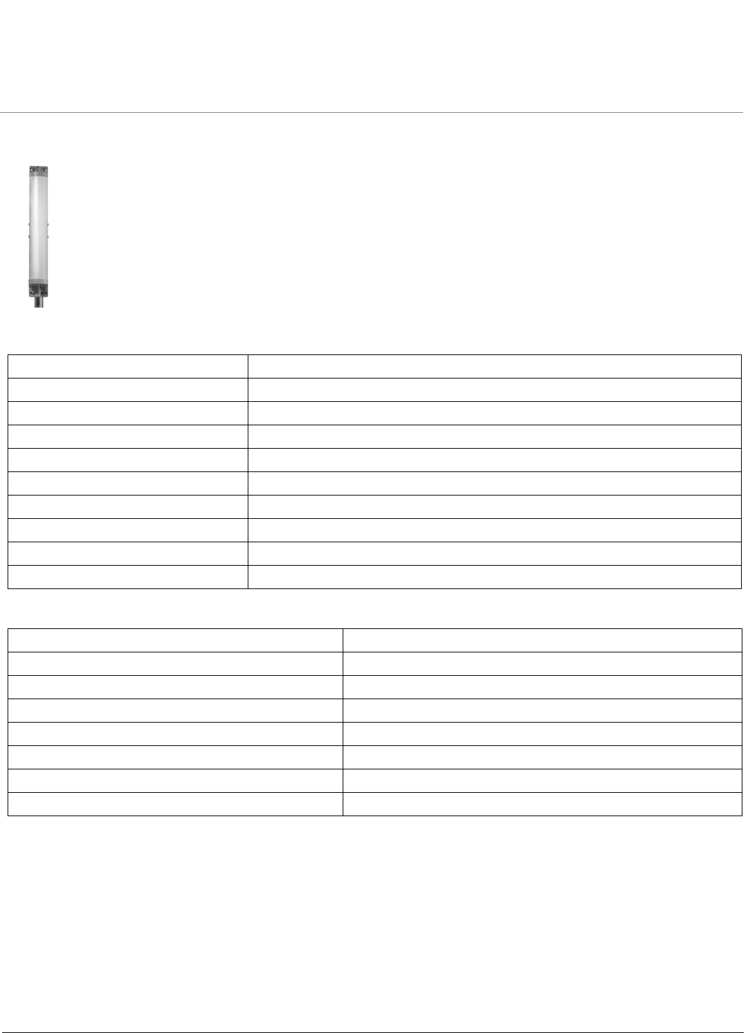
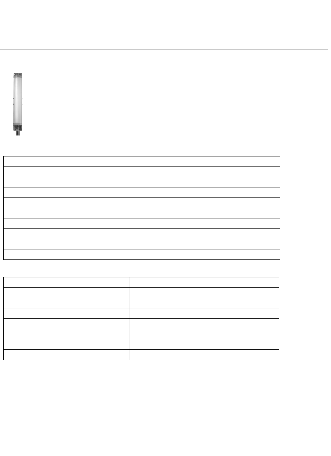
17 dBi Sector Antenna (60°) (5054-SA60-17)
Electrical Specifications
Environmental and Mechanical Specifications
Frequency Range 5150 MHz – 5875 MHz
VSWR 2.0 : 1 maximum
Nominal Impedance 50 Ohms
Gain 16.5 dBi
HPBW/Horizontal 60°
HPBW/Vertical 6°
Polarization Linear, Vertical
Downtilt 0°
Power Handling 5 W (cw)
Connector Type N-type Female
Wind Survival (per EIA-222-F at 100’ height) 216 km/hr
Temperature Range -40 to +80 °C
Humidity 95% @ 25 °C
Lightning Protection DC Ground
Size 620 x 88 x 70 mm
Radome Color Gray
Radome Material ABS
Weight 530 g
Recommended 5 GHz Antennas ORiNOCO Series System Recommended Antennas
Sector Antennas
48
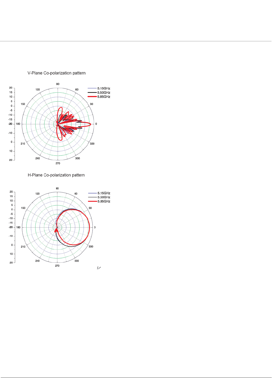
17 dBi Sector Antenna (60°) (5054-SA60-17) (continued)
Antenna Patterns

Recommended 5 GHz Antennas ORiNOCO Series System Recommended Antennas
Sector Antennas
49
Other Recommended Sector Antennas
Beamwidth Manufacturer Model Number Frequency Range Mid-Band Gain
60° Mars
MTI
MTI
MTI
RadioWaves
RadioWaves
MA-WC50-5X
MT-484026/NV
MT-484026/NH
MT-484033/NV
SEC-55H-60-17
SEC-55V-60-17
5.15 – 5.85
5.15 – 5.875
5.15 – 5.875
5.15 – 5.875
5.25 – 5.85
5.25 – 5.85
17
16 (Null-Fill)
15 (h pol, NF)
16.5
17 (hor pol)
17
90° Mars
MTI
MTI
MTI
RadioWaves
RadioWaves
Telex
Telex
MA-WD50-6X
MT-484027/NV
MT-484027/NH
MT-484032/NV
SEC-55H-90-16
SEC-55V-90-16
5801
5840
5.15 – 5.875
5.15 – 5.875
5.15 – 5.875
5.15 – 5.85
5.25 – 5.85
5.25 – 5.85
5.725 – 5.825
5.725 – 5.825
16
14 (Null-Fill)
14 (h pol, NF)
17
16 (hor pol)
16
12
15
120° Mars
MTI
MTI
RadioWaves
RadioWaves
MA-WE50-7X
MT-484034/NV
MT-484034/NH
SEC-5V-120-14
SEC-5V-120-16
5.15 – 5.875
5.15 – 5.875
5.15 – 5.875
5.725 – 5.85
5.725 – 5.85
14.5
16.5
16.5 (hor pol)
14
16
Recommended 5 GHz Antennas ORiNOCO Series System Recommended Antennas
Panel Antennas
50
Panel Antennas
•15 dBi Window Antenna (5054-WA-15-STN)
•18 dBi Panel Antenna (5054-PA-18)
•23 dBi Panel Antenna (5054-PA50-23)
•Other Recommended Panel Antennas
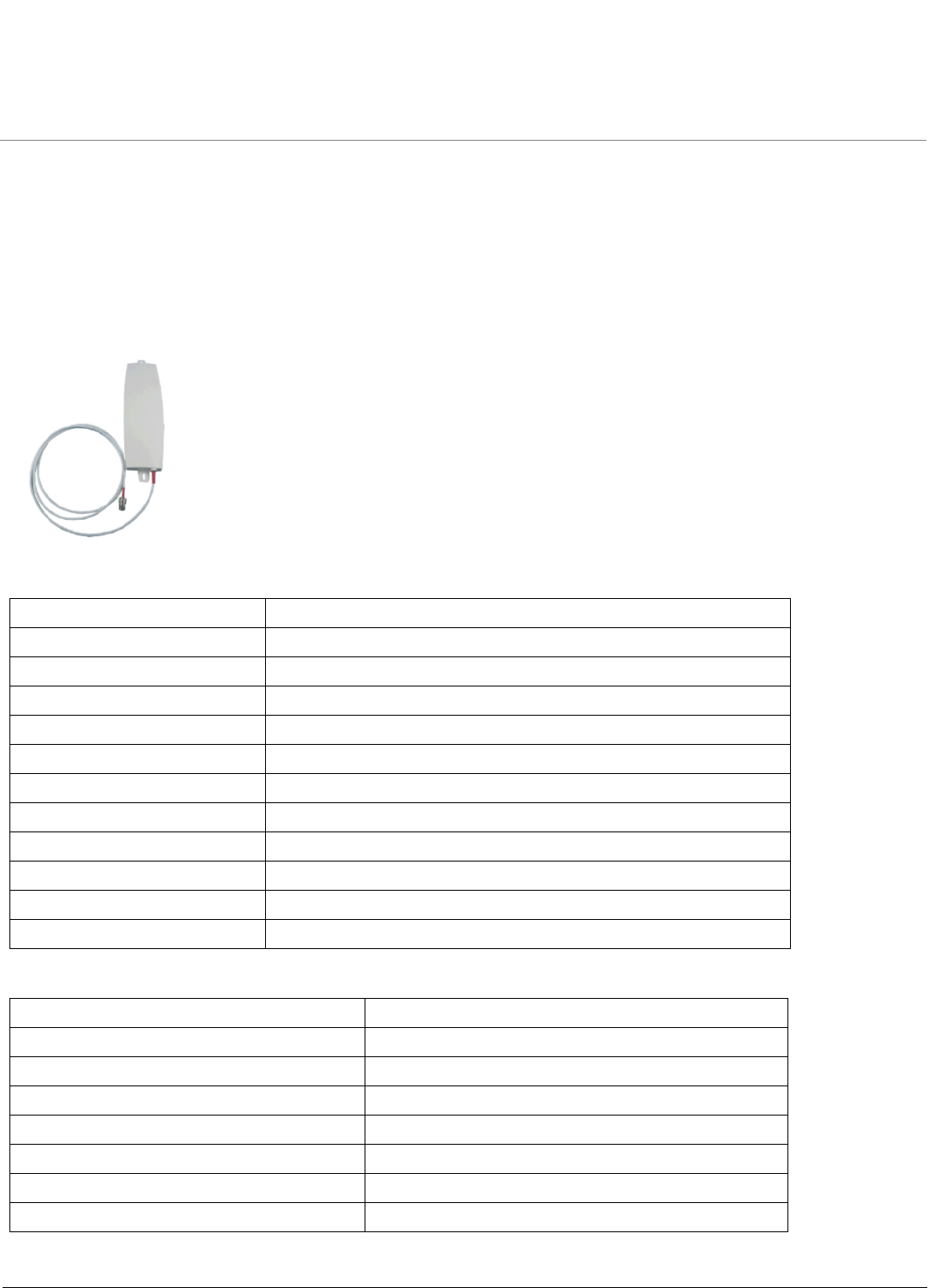
15 dBi Window Antenna (5054-WA-15-STN)
Electrical Specifications
Environmental and Mechanical Specifications
Frequency Range 5150 MHz – 5850 MHz
VSWR 2.0 : 1 maximum
Nominal Impedance 50 Ohms
Gain* 15 dBi
HPBW/Horizontal 45°
HPBW/Vertical 10°
Polarization Linear, Vertical
Downtilt 0°
Power Handling 20 W (cw)
Connector Type Standard N Female
Front-to-Back Ratio 18 dB
Impedance 50 Ohms
Wind Survival 180 km/hr
Temperature Range -40 to +80 °C
Humidity 95% @ 25 °C
Lightning Protection DC ground
Size 330 x 93 x 21 mm
Radome Color White
Radome Material ABS, UV Resistant
Weight 0.6 kgw
Recommended 5 GHz Antennas ORiNOCO Series System Recommended Antennas
Panel Antennas
51
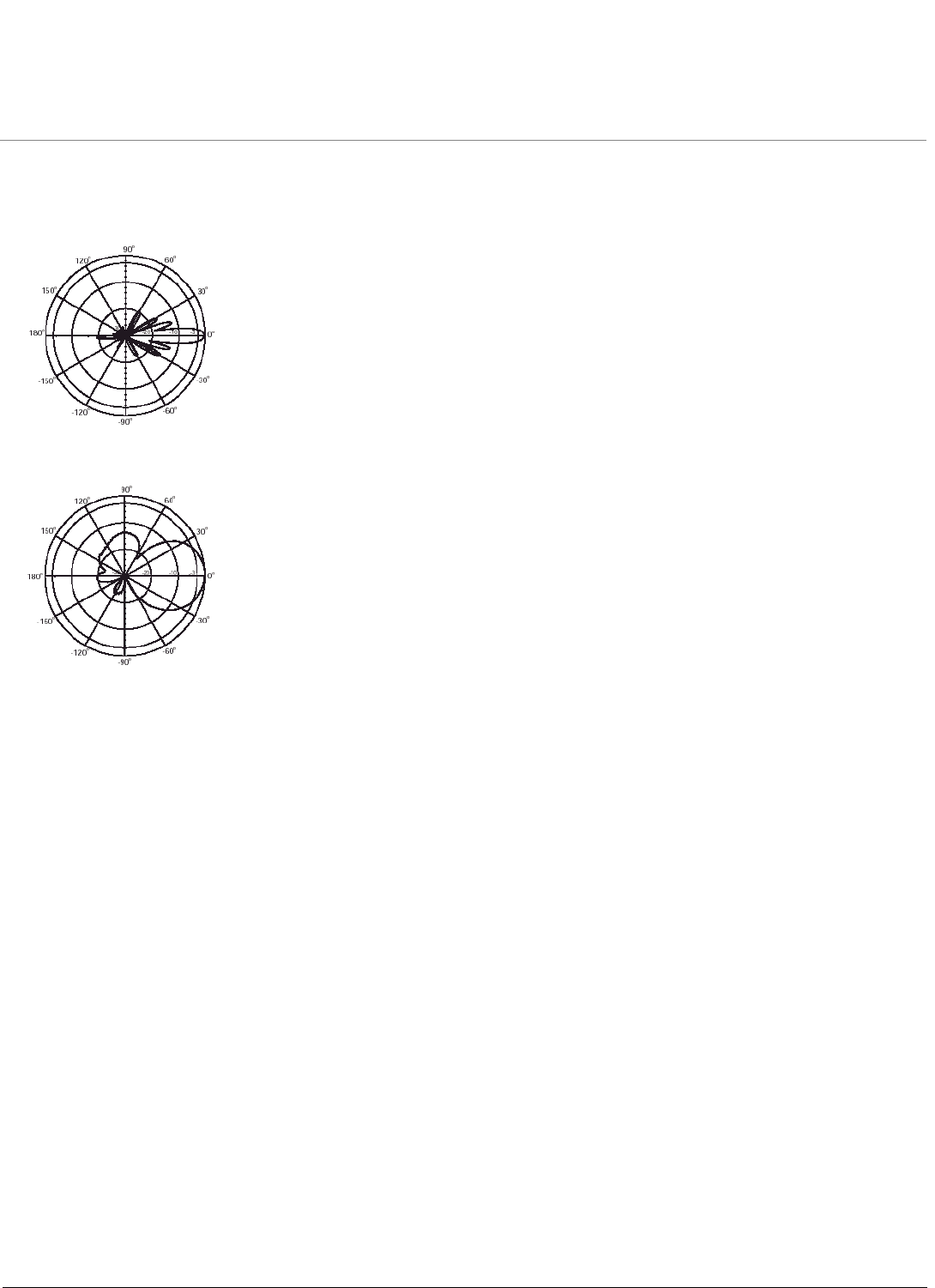
15 dBi Window Antenna (5054-WA-15-STN) (continued)
Antenna Patterns
Vertical
Horizontal
Recommended 5 GHz Antennas ORiNOCO Series System Recommended Antennas
Panel Antennas
52
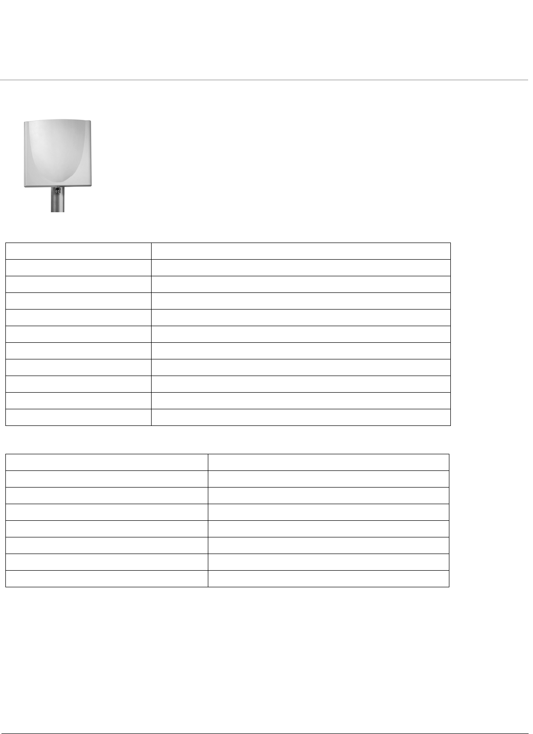
18 dBi Panel Antenna (5054-PA-18)
Electrical Specifications
Environmental and Mechanical Specifications
Frequency Range 5250 MHz – 5785 MHz
VSWR 1.5 : 1 maximum
Nominal Impedance 50 Ohms
Gain 18 dBi
HPBW/Horizontal 18°
HPBW/Vertical 18°
Polarization Linear, Vertical
Downtilt 0°
Power Handling 10 W (cw)
Connector Type Standard N Female
Front-to-Back Ratio 30 dB
Wind Survival (per EIA-222-F at 100’ height) 216 km/hr
Temperature Range -40 to +80 °C
Humidity 95% @ 25 °C
Lightning Protection DC ground
Size 200 x 200 x 50 mm
Radome Color Light Gray
Radome Material ABS, UV Resistant
Weight 0.825 kgw
Recommended 5 GHz Antennas ORiNOCO Series System Recommended Antennas
Panel Antennas
53
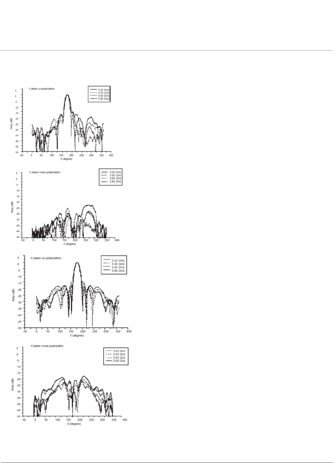
18 dBi Panel Antenna (5054-PA-18) (continued)
Antenna Patterns

Recommended 5 GHz Antennas ORiNOCO Series System Recommended Antennas
Panel Antennas
54
23 dBi Panel Antenna (5054-PA50-23)
Electrical Specifications
Environmental and Mechanical Specifications
Frequency Range 5150 MHz – 5875 MHz
VSWR 2:0: 1 maximum
Nominal Impedance 50 Ohms
Gain 23 dBi
HPBW/Horizontal 9°
HPBW/Vertical 9°
Polarization Linear
Power Handling 5 W
Connector Type N Jack
Front-to-Back Ratio 30 dB
Wind Survival 216 km/hr
Temperature Range -40 to +80 °C
Humidity 95% @ 55 °C
Lightning Protection DC Ground
Size 320 x 320 x 18 mm
Radome Color Gray-White
Radome Material PC, UV Resistant
Weight 1.2 kg
Recommended 5 GHz Antennas ORiNOCO Series System Recommended Antennas
Panel Antennas
55
Antenna Patterns

Recommended 5 GHz Antennas ORiNOCO Series System Recommended Antennas
Panel Antennas
56
Other Recommended Panel Antennas
Type Manufacturer Model Number Frequency Range Mid-Band Gain
Panel SmartAnt
Gabriel
MTI
MTI
MTI
Mars
RadioWaves
R0320-056
DFPS.5-52
MT-485001/N
MT-485028/N
MT-486004/N
MA-WA57-3X
FP .5-5-18
5.15 – 5.875
5.25 – 5.85
5.15 – 5.875
5.15 – 5.875
5.15 – 5.875
5.15 – 5.875
5.25 – 5.85
8
18
18
22
26
17.5
18
1-Foot Flat Panel Gabriel
Andrew
MTI
Mars
RadioWaves
DFPD1-52
FPA5250D12-N
485002/N
MA-WA58-1X
FP1 5-24
5.25 – 5.85
5.25 – 5.85
5.15 – 5.875
5.15 – 5.875
5.25 – 5.85
23.5
23.6
23
23
24
2-Foot Flat Panel MTI
Gabriel
Andrew
RSI
RadioWaves
MT-486001/N
DFPD2-52
FPA5250D24-N
A57A24-U
FP2 5-28
5.15 – 5.875
5.25 – 5.85
5.25 – 5.85
5.725 – 5.85
5.25 – 5.85
28
28
28.2
26.5
28

Recommended 5 GHz Antennas ORiNOCO Series System Recommended Antennas
Parabolic Antennas
57
Parabolic Antennas
Recommended parabolic antennas for 5 GHz are listed in the following table.
Type Manufacturer Model Number Frequency Range Mid-Band Gain
2-Foot Parabolic Gabriel
Gabriel
Gabriel
Radio Waves
Radio Waves
Andrew
Andrew
RSI
SSP2-52B
SSD2-52A
HSSP2-52
SP2-5.2
SPD2-5.2
P2F-52
PX2F-52
P-57C24
5.25 – 5.85
5.25 – 5.85
5.25 – 5.85
5.25 – 5.85
5.25 – 5.85
5.25 – 5.85
5.25 – 5.85
28.5
28.4
28.1
28.3
28.1
29.4
29.4
29
3-Foot Parabolic Radio Waves
Radio Waves
Andrew
Andrew
SP3-5.2
SPD3-5.2
P3F-52
PX3F-52
5.25 – 5.85
5.25 – 5.85
5.25 – 5.85
5.25 – 5.85
31.4
31.1
33.4
33.4

ORiNOCO Series System Recommended Antennas
58
6
Technical Services and Support
Obtaining Technical Services and Support
If you are having trouble utilizing your Proxim product, please review this manual and the additional documentation
provided with your product.
If you require additional support and would like to use Proxim’s free Technical Service to help resolve your issue, please
be ready to provide the following information before you contact Proxim’s Technical Services:
•Product information:
– Part number of suspected faulty unit
– Serial number of suspected faulty unit
•Trouble/error information:
– Trouble/symptom being experienced
– Activities completed to confirm fault
– Network information (what kind of network are you using?)
– Circumstances that preceded or led up to the error
– Message or alarms viewed
– Steps taken to reproduce the problem
•Servpak information (if a Servpak customer):
– Servpak account number
•Registration information:
– If the product is not registered, date when you purchased the product
– If the product is not registered, location where you purchased the product
NOTE: If you would like to register your product now, visit the Proxim eService Web Site at
http://support.proxim.com and click on New Product Registration.

Technical Services and Support ORiNOCO Series System Recommended Antennas
Support Options
59
Support Options
Proxim eService Web Site Support
The Proxim eService Web site is available 7x24x365 at http://support.proxim.com.
On the Proxim eService Web Site, you can access the following services:
•New Product Registration: Register your product for free support.
•Open a Ticket or RMA: Open a ticket or RMA and receive an immediate reply.
•Search Knowledgebase: Locate white papers, software upgrades, and technical information.
•ServPak (Service Packages): Receive Advanced Replacement, Extended Warranty, 7x24x365 Technical Support,
Priority Queuing, and On-Site Support.
•Your Stuff: Track status of your tickets or RMAs and receive product update notifications.
•Provide Feedback: Submit suggestions or other types of feedback.
•Customer Survey: Submit an On-Line Customer Survey response.
•Repair Tune-Up: Have your existing Proxim equipment inspected, tested, and upgraded to current S/W and H/W
revisions, and extend your warranty for another year.
Telephone Support
Contact technical support via telephone as follows:
•US and Canada: 408-383-7700, 866-674-6626 (Toll Free)
Hours of Operations: 8AM - 6PM
• APAC Countries: +91 40-23115490
Hours of Operations: 9AM - 6PM
•International: 408-383-7700
Hours of Operations: 8AM - 6PM
ServPak Support
Proxim understands that service and support requirements vary from customer to customer. It is our mission to offer
service and support options that go above-and-beyond normal warranties to allow you the flexibility to provide the quality
of service that your networks demand.
In recognition of these varying requirements we have developed a support program called ServPak. ServPak is a
program of Enhanced Service Options that can be purchased individually or in combinations to meet your needs.
•Advanced Replacement: This service offers customers an advance replacement of refurbished or new hardware.
(Available in the U.S., Canada, and select countries. Please inquire with your authorized Proxim distributor for
availability in your country.)
•Extended Warranty: This service provides unlimited repair of your Proxim hardware for the life of the service
contract.
•7x24x365 Technical Support: This service provides unlimited, direct access to Proxim’s world-class technical
support 24 hours a day, 7 days a week, 365 days a year.
•Priority Queuing: This service allows your product issue to be routed to the next available Customer Service
Engineer.
To purchase ServPak support services, please contact your authorized Proxim distributor. To receive more information
or for questions on any of the available ServPak support options, please call Proxim Support at 408-383-7700 or send an
email to servpak@proxim.com.