Proxim Wireless S58-B60 Tsunami Multipoint Base Station Unit User Manual Backing down from TNG CCI 2
Proxim Wireless Corporation Tsunami Multipoint Base Station Unit Backing down from TNG CCI 2
Contents
Installation manual part 3
Tsunami Multipoint Version 1.3 Installation Guide
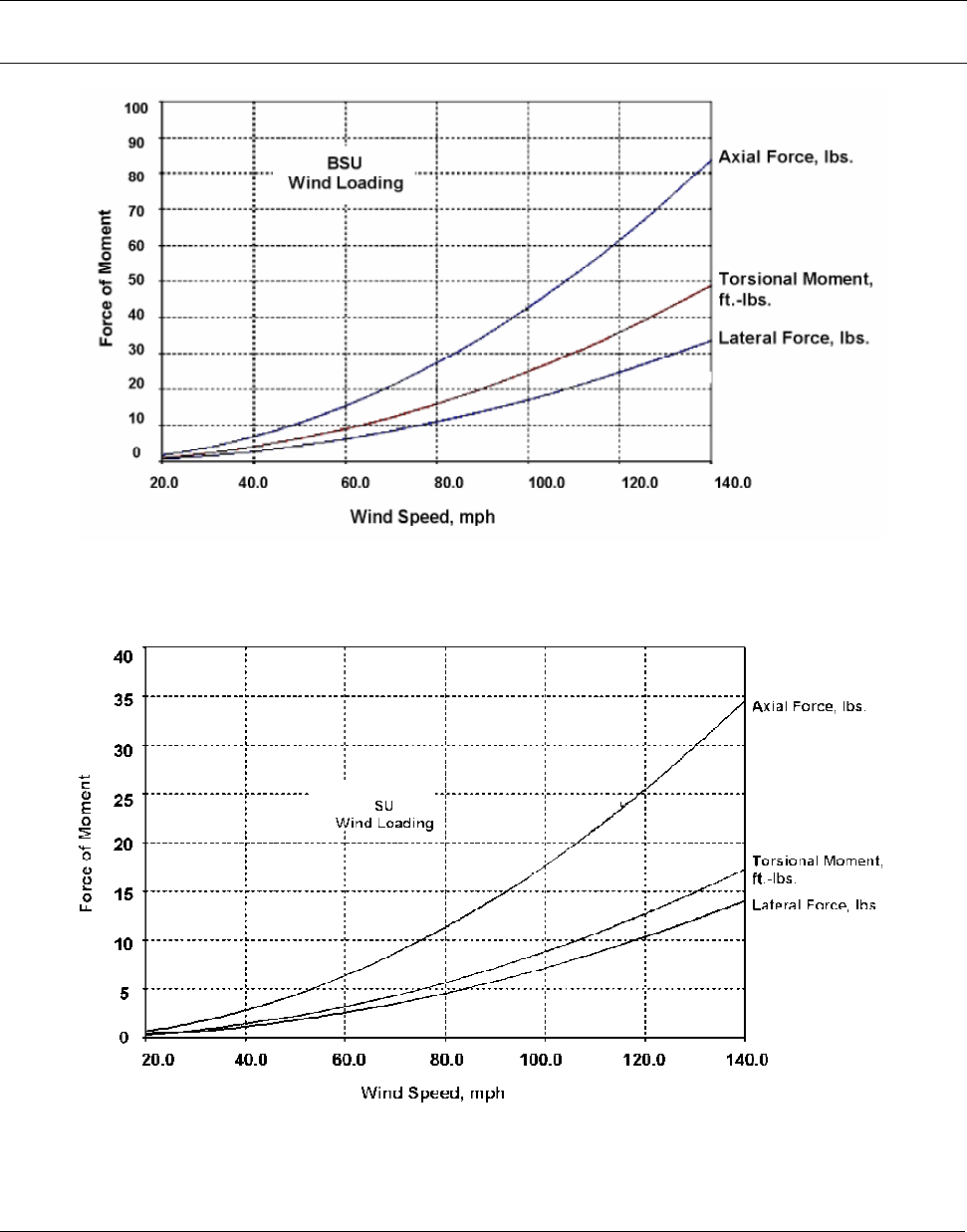
4.45 to obtain newtons, or by 0.45 to obtain kilograms of force. Similarly, foot-pounds can be multiplied
by 1.36 to obtain Newton-meters, or by 0.138 to obtain kgm-meters.
Note: For definitions of wind loading specifications for antennas and towers, refer to TIA/EIA-195 (for antennas) or
TIA/EIA-222 (for towers) specifications.
Figure 1. BSU Wind Loading Analysis
Figure 2. SU Wind Loading Analysis
Chapter 1. Site Planning 9
CPN 63179 Issue Date: 01/24/03

Tsunami Multipoint Version 1.3 Installation Guide
Lightning
You should always consider the potential for lightning damage to radio equipment when planning a
wireless link. A variety of lightning-protection and grounding devices are available for use on buildings,
towers, antennas, cables, and equipment that could be damaged by a lightning strike, whether located
inside or outside the site.
Lightning protection requirements are based upon the exposure at the site, the cost of link down-time,
and local building and electrical codes. If the link is critical and the site is in an active lightning area,
attention to thorough lightning protection and grounding is critical.
Lightning Protection
To provide effective lightning protection, install antennas in locations that are unlikely to receive direct
lightning strikes, or install lightning rods to protect antennas from direct strikes. Make sure that cables
and equipment are properly grounded to provide low-impedance paths for lightning currents. Install
surge suppressors on adjacent telephone lines and power lines.
Users should provide additional lightning protection for cables leading to the wireless radio as well as to
and from the power supply in regions that have extreme lightning occurrences. This optional lightning
protection should be placed at points close to where the cable passes through the bulkhead into the
building, as well as near the BSU/SU. A grounding screw is provided on the BSU and SU.
For indoor applications, you can use the Erico LAN-RJ45 Local Area Network Protector (see Erico’s web
site, http://www.erico.com for information); for outdoor applications, you can use lightning protectors
from PolyPhaser (see the Polyphaser web site, http://www.polyphaser.com ).
See “Appendix E. Lightning Protection Recommendations” on page 70 for more information.
Category 5 Cable
When the entire power and Ethernet cable is encased in steel conduit from the building entrance to the
radio, no surge arrestors are required. Otherwise, each power and Ethernet cable requires one surge
arrestor within two feet of the building entrance.
Interference and How to Avoid It
An important part of planning your broadband fixed wireless system is the avoidance of interference.
Interference can be caused by effects outside the system. Good RF planning can overcome most
interference challenges.
Note: The Tsunami Multipoint product line includes a BSU that provides spectrum shielding. This BSU model can
reject interference at the uplink location. If interference from other systems is a problem, Proxim
recommends you use a BSU equipped with this feature.
Chapter 1. Site Planning 10
CPN 63179 Issue Date: 01/24/03

Tsunami Multipoint Version 1.3 Installation Guide
Co-Channel and Adjacent Channel Interference
Co-channel interference results when another RF link is using the same channel frequency. Adjacent-
channel interference results when another RF link is using an adjacent channel frequency. In selecting a
site, a spectrum analyzer can be used to determine whether any strong signals are present and, if
present, determine how close they are to the desired frequency. The further removed from your
proposed frequency, the less likely they are to cause a problem.
Antennas
Antennas frequently play a key role in reducing the potential for interference. They come in a variety of
configurations that have different performance characteristics in the areas of gain and direction. Antennas
that transmit/receive in all directions are known as omni-directional, while those that transmit/receive
in one specific direction are categorized as directional. Antennas also vary in beamwidth, which is the
aperture to which they can “see” signals. Larger antennas typically provide narrower beamwidths and
can diminish interference from nearby transmitters by:
▪ Focusing RF energy from the intended destination
▪ Reducing the power of interfering sources not directly aligned to the antenna
Tsunami Multipoint Ethernet Systems use integrated directional antennas that transmit and receive a
relatively narrow beamwidth of radio energy, improving system performance by reducing the likelihood
that surrounding RF clutter will interfere with reception. The antennas with this system are directional
and cannot be detached.
Chapter 1. Site Planning 11
CPN 63179 Issue Date: 01/24/03
Tsunami Multipoint Version 1.3 Installation Guide
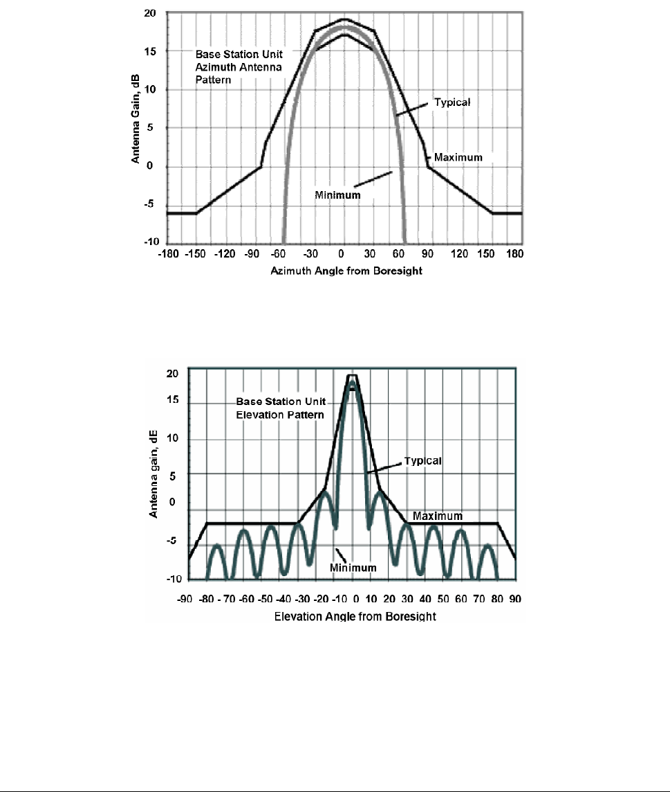
BSU Antenna Characteristics
Polarization: LHCP (Left-Hand Circular Polarization)
Azimuth Beamwidth: 60-degree
Elevation Beamwidth: 6-degree
Figure 3. BSU Azimuth Antenna Pattern
Figure 4. BSU Elevation Antenna Pattern
Chapter 1. Site Planning 12
CPN 63179 Issue Date: 01/24/03
Tsunami Multipoint Version 1.3 Installation Guide
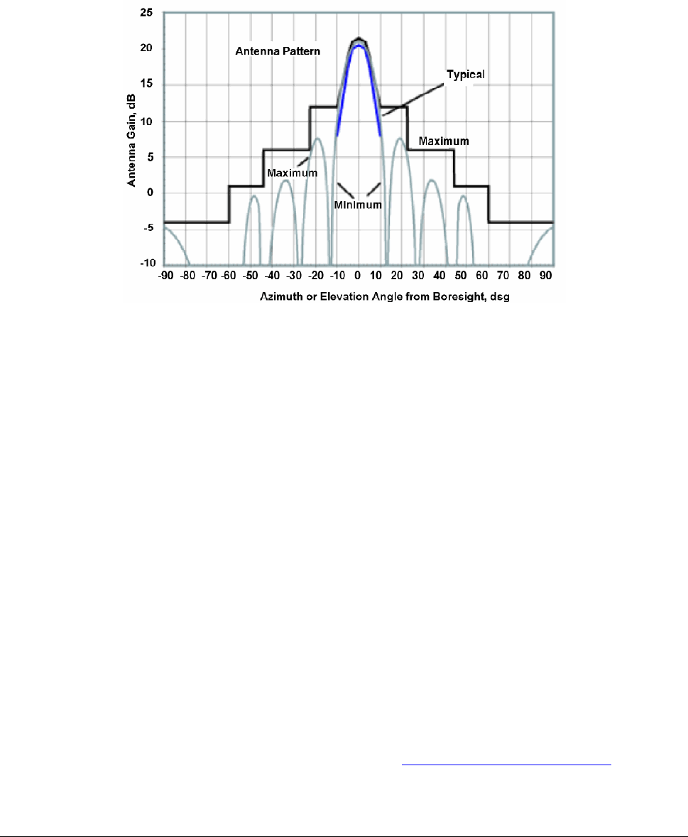
SU Antenna Characteristics
Polarization: LHCP
Beamwidth (Azimuth/Elevation): 10-degree
Figure 5. SU Antenna Pattern
Even when other licensees are not an issue, if you are using a network deployment using the “cell”
approach, all these considerations are still important for reducing interference between your own
adjacent installations. Antennas are tuned to operate on a specific group of frequencies.
Antenna Polarization
The Tsunami Multipoint system uses left-hand circular polarization. As a result, the signal is
successfully received regardless of the orientation of the antenna. Circular polarization also provides
protection against multi-path degradation of the signal quality.
Towers
When planning antenna placement, it might be necessary to build a free-standing tower for the antenna.
Regulations and limitations define the height and location of these towers with respect to airports,
runways, and airplane approach paths. These regulations are controlled by the FAA. In some
circumstances, the tower installations must be approved by the FAA, registered with the FCC, or both.
To ensure compliance, review the current FCC regulations regarding antenna structures. These
regulations (along with examples) are on the FCC web site at http://wireless.fcc.gov/antenna/ .
Chapter 1. Site Planning 13
CPN 63179 Issue Date: 01/24/03

Tsunami Multipoint Version 1.3 Installation Guide
Path Planning
To get the most value from a wireless system, path planning is essential. In addition to the fact that
radio signals dissipate as they travel, many other factors operate on a microwave signal as it moves
through space. All of these must be taken into account, because any obstructions in the path can
attenuate the signal.
Calculating a Link Budget
A link budget is a rough calculation of all known elements of the link to determine whether the signal
will have the proper strength when it reaches the other end of the link. To make this calculation, consider
the following information.
▪ A signal degrades as it moves through space. The longer the path, the more loss it experiences. This
free-space path loss is a factor in calculating the link viability. Free-space path loss is easily
calculated for miles or kilometers.
▪ Availability represents the quality of a link. It is the ratio of the time that the link is available to the
total time. This serves as a guide to the service you can expect, on the average, over a period of one
year.
You can lower the bit error rate (BER), resulting in greater reliability, by reducing the data throughput or
reducing the distance between the BSU and the SU.
Note: In terrestrial communication, path loss does not necessarily follow 20dB per decade degradation as used in
free-space loss. Instead, 25-35 dB per decade is more common in a metropolitan near-line-of-sight
environment.
Unlicensed Frequencies (U-NII)
The FCC has identified the frequencies from 5.725 to 5.825 GHz as Unlicensed National Information
Infrastructure (U-NII). This band can be used by anyone without having to obtain a license. However, you
must use radio equipment that is “type approved” by the FCC or local government for use within the
specific band.
PMP Radio Information
The following sections provide information about the Tsunami Multipoint radio components. See
“Appendix C. Technical Specifications” on page 57 for product technical specifications.
Chapter 1. Site Planning 14
CPN 63179 Issue Date: 01/24/03

Tsunami Multipoint Version 1.3 Installation Guide
Channel/Frequency Plans
Tsunami Multipoint offers several frequency plans to provide a means for overcoming interference. If one
part of the 5.8 GHz spectrum is occupied when you deploy the product, you can select a different
frequency plan to bypass the interfering frequency. Plan 4 is the default. Operating frequencies in the 5
and 6 plans overlap. See “Change the Frequency Plan and Operating Frequency” on page 50 for more
information.
Bandwidth
The Tsunami Multipoint offers four modulation modes: QAM16 (60 Mbps), QAM8 (40 Mbps), QPSK3Q (30
Mbps), and QPSK1H (20 Mbps) with equal bandwidth occupancy (3 dB BW at 20.75MHz, 26dB BW at
26MHz). Downlink and uplink signals are divided into time slots, with the number of slots per frame
varying, depending upon the current modulation mode and data rate. Furthermore, the ratio of slots
assigned to downlink and uplink is commandable (within limits; see “setFirstInboundSlot” in the Tsunami
Multipoint Version 1.3 Reference Manual for details)
Tx Power and Antenna Specifications
See “Tx Power,” “txPowerLevel,” and “Antennas” in the Tsunami Multipoint Version 1.3 Reference
Manual.
Power Control
Each SU automatically adjusts its transmit power so the strength of its signal at the BSU does not exceed
the limitation imposed by the Inbound Power Control (IPC) margin. This ensures fair access for all SUs
regardless of distance from the BSU. In addition, IPC can be increased to overcome interference. See
the “IPC” command in the Tsunami Multipoint Version 1.3 Reference Manual for more information.
Chapter 1. Site Planning 15
CPN 63179 Issue Date: 01/24/03
Tsunami Multipoint Version 1.3 Installation Guide
Chapter 2. Deploying the Base Station Unit (BSU)
This chapter describes how to mount and deploy the Base Station Unit including the GPS Antenna
(required when you install multiple BSUs at the same location).
Unpacking the System
The product’s shipping boxes should be left intact and sheltered until arrival at the installation site. If the
shipping container shows signs of damage, immediately notify the transportation company. Upon receipt,
inspect contents to make sure no parts are missing or damaged.
Proxim recommends that you retain all the packaging materials (including all internal boxes). In the
unlikely event that the equipment must be returned to the factory, use the original packing materials for
return shipment. The packaging materials are also recommended for transporting the equipment from
location to location.
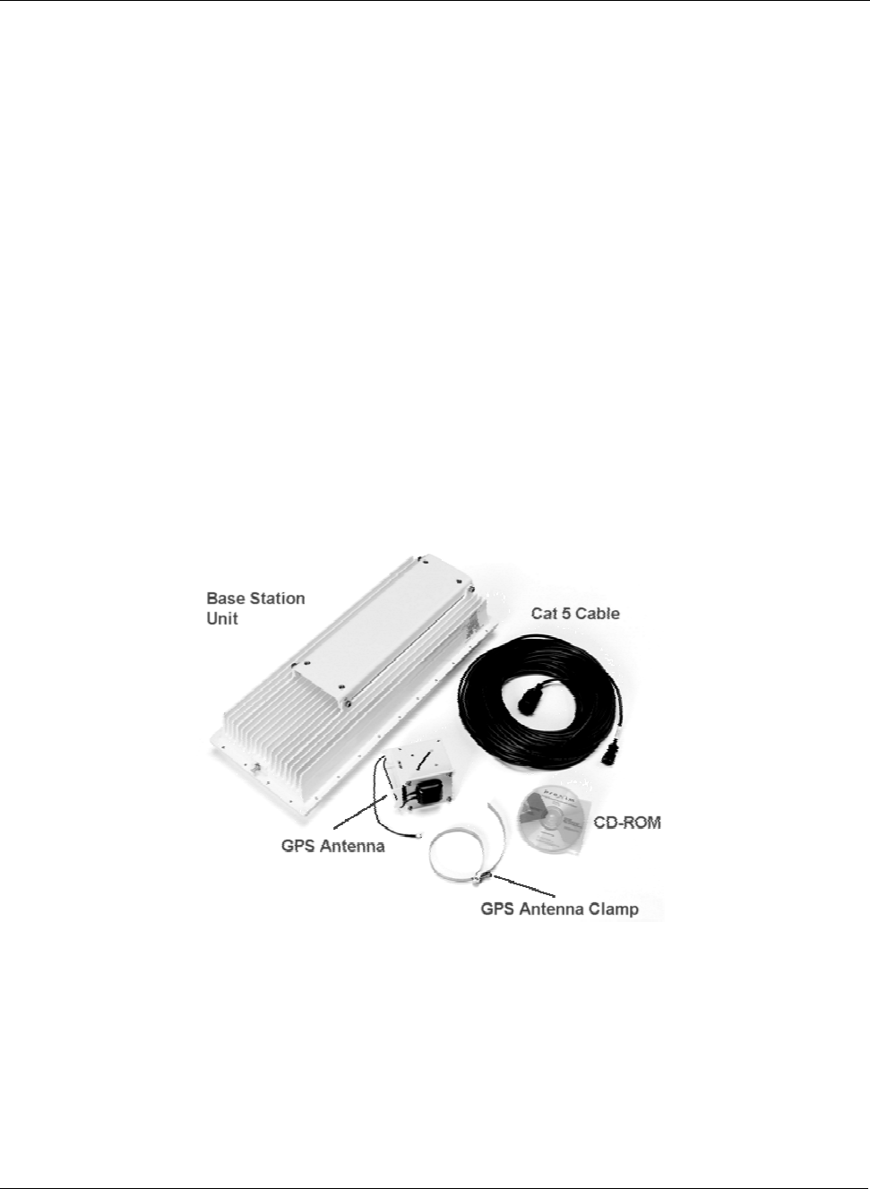
Unpack the following items from the contents of the shipping box. In addition to these items, you will
require an additional Cat 5 cross-over or straight-through cable (see step 5) and a BSU power adapter
(the BSU’s power supply is ordered and shipped separately; the power supply’s CPN number is 58526).
Figure 6. Base Station Unit Components
The product’s shipping boxes should be left intact and sheltered until arrival at the installation site. If the
shipping container shows signs of damage, immediately notify the transportation company. Upon receipt,
inspect contents to make sure no parts are missing or damaged.
Chapter 2. Deploying the Base Station Unit (BSU) 16
CPN 63179 Issue Date: 01/24/03