Proxim Wireless S58-B60 Tsunami Multipoint Base Station Unit User Manual Backing down from TNG CCI 2
Proxim Wireless Corporation Tsunami Multipoint Base Station Unit Backing down from TNG CCI 2
Contents
Installation manual part 6

Tsunami Multipoint Version 1.3 Installation Guide
Monitor the Es/No ratio (Es/No reports the energy per symbol-to-noise spectral density ratio (in dB)).
Low Es/N0 or varying Es/N0 can indicate path or interference problems. The Es/No requirement varies
based on the modulation mode:
20 Mbps: Es/No > 4 + IPC value
30 Mbps: Es/No > 5 + IPC value
40 Mbps: Es/No > 9 + IPC value
60 Mbps: Es/No > 12 + IPC value
In addition, the BSU log provides the following information:
Int
Relative interference of the power received at the BSU (a value of 0 (zero) nominally shows no
interference)
GPS sync
-1 indicates GPS sync is disabled; 4 indicates GPS sync is enabled. GPS synchronization is used when
the system is in Multi Sector mode (multiple BSUs installed in the same location; see “Configuring the
System for Multi-Sector Mode” on page 29 for more information).
SU ID
The Terminal ID of the monitored SU
Time error
Shows the uplink (or inbound) ranging error
Rx cell error
Shows the number of lost uplink cells
Rx cells
Shows the total number of uplink cells
Time
Shows the cumulative polling time (in seconds)
Displaying the SU Logs
You can display two different types of SU logs: SUlog1 and SUlog2. To display the SU logs, install the
Base Station Configuration Software on the PC used to configure the SU (see “Installing the Base Station
Configuration Software” for information) and then execute the commands described below.
Follow these steps to enable an SU log:
1. Enter SUlog1 <time> or SUlog2 <time> where <time> specifies the polling period (in seconds).
(Specify SUlog1 to display SUlog1; specify SUlog2 to display SUlog2. See the information below for
details about these two logs.)
Chapter 4. System Diagnostics and Operating Tips 41
CPN 63179 Issue Date: 01/24/03

Tsunami Multipoint Version 1.3 Installation Guide
2. When finished, disable the SU log by entering SUlog1 0 (zero) or SUlog2 0 (zero) (depending upon
which log you displayed).
SUlog1 provides the following information:
SU ID
The Terminal ID of the monitored SU.
RSL
Shows the shows the RSL (receiver signal level) at the output of the antenna (in dBm).
TX Power
Shows the SU’s TX power at the input to the antenna (in dBm).
VCO
Shows the relative frequency offset of the VCO (voltage control oscillator) (in Hz).
Time error
Shows the synchronization error (in 1/512 symbol), generally magnitude (should be less than 8).
OB pkt error
Shows the number of out-of-sequence outbound packets.
Range
Shows the SU’s distance from the BSU (in meters).
Figure 25. Log 1
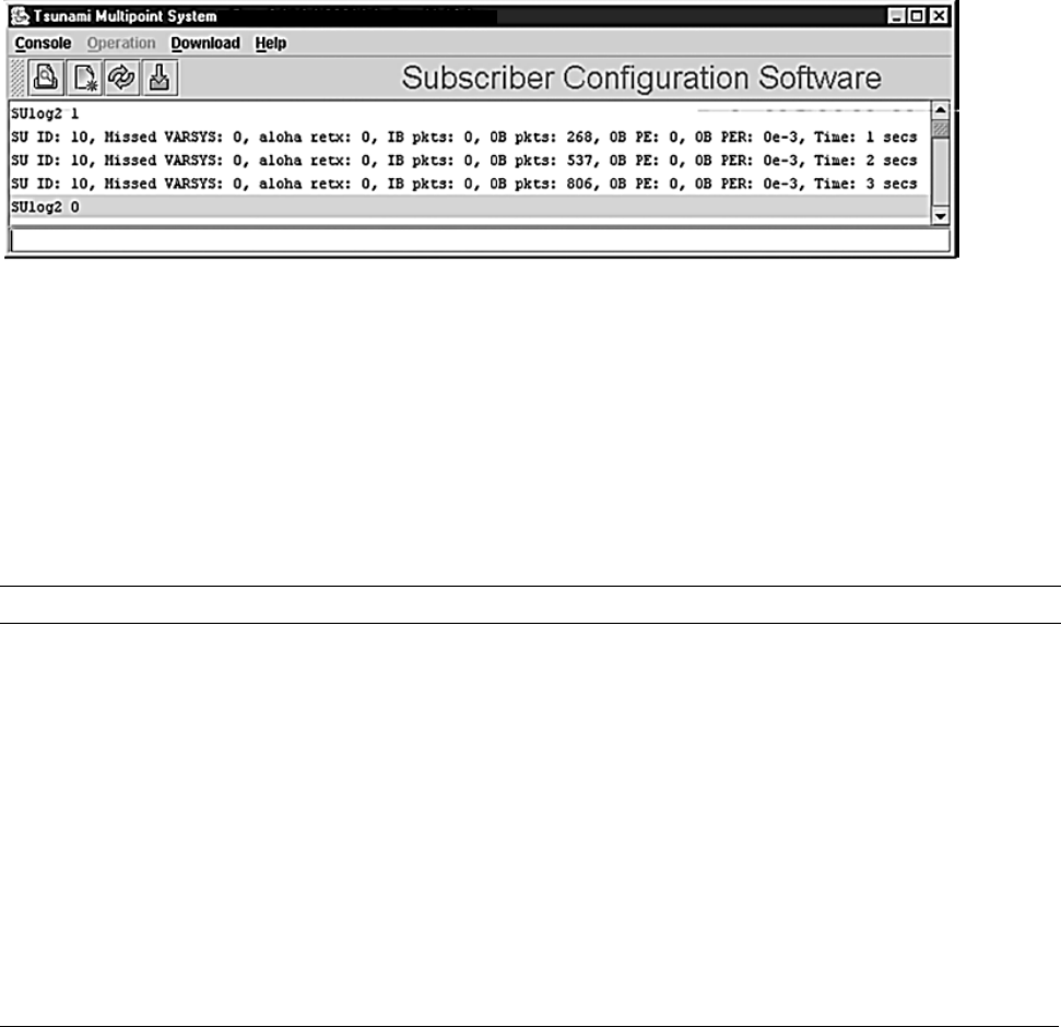
SUlog2 provides the following information:
SU ID
The Terminal ID of the monitored SU.
Missed VARSYS
Shows the number of missing downlink control packets.
aloha retx
Shows the number of packets retransmitted due to collisions (collisions are a normal event on
contingent channels. An excessive number may indicate a problem).
Chapter 4. System Diagnostics and Operating Tips 42
CPN 63179 Issue Date: 01/24/03
Tsunami Multipoint Version 1.3 Installation Guide
IB pkts
Shows the number of inbound packets transmitted.
OB pkts
Shows the number of outbound packets received.
OB PE
Shows the number of outbound packet errors.
OB PER
Shows the error rate for outbound packets received.
Time
Shows the cumulative polling time (in seconds).
Figure 26. SU Log 2
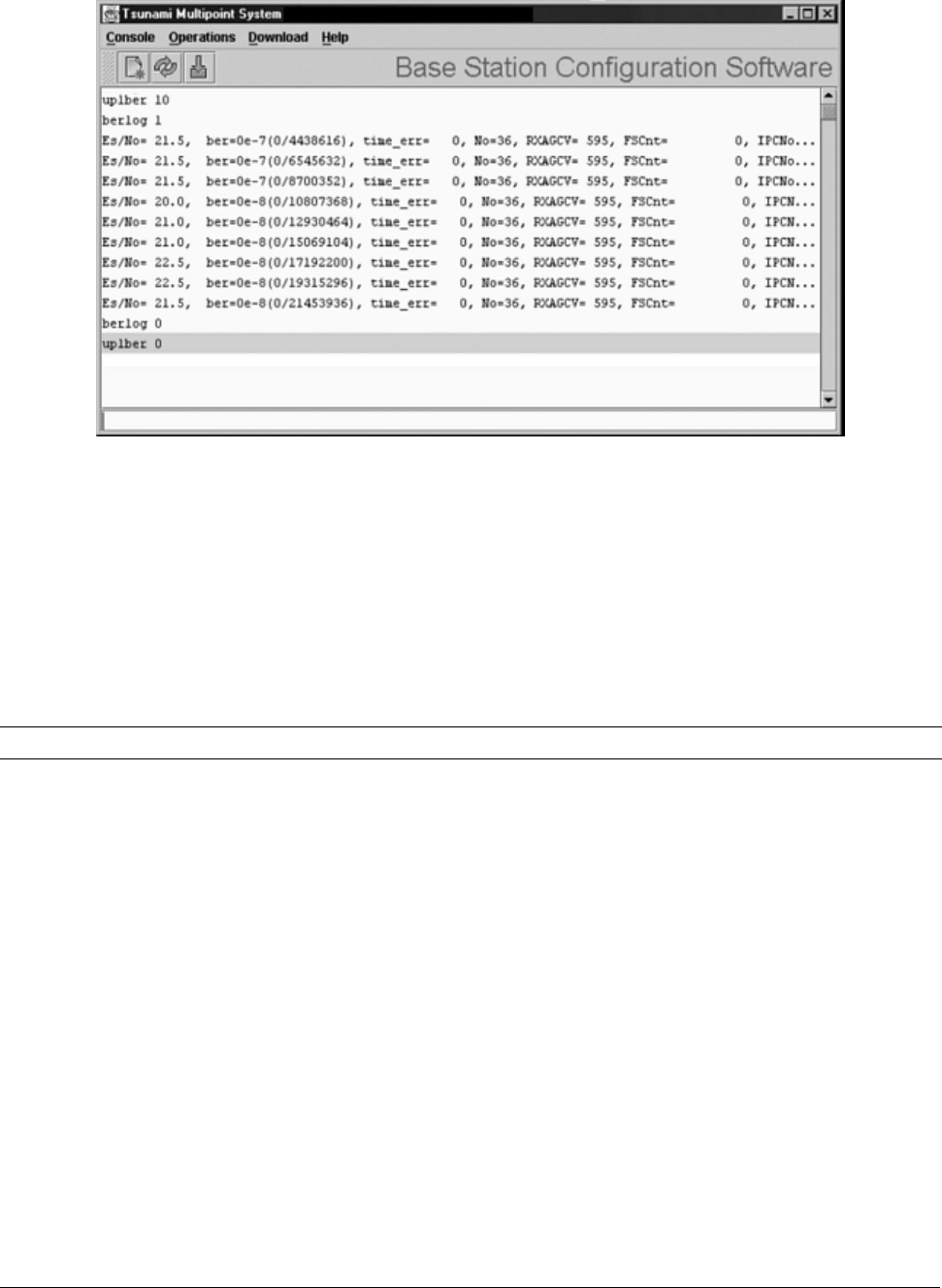
Uplink BER Test
The Uplink BER Test determines the BER (bit error rate) of the uplink signal. This is an out-of-service
diagnostic tool and the data connection is terminated for the length of the test. Use this tool to determine
whether the link is stable (that is, there are no bit errors). You can also monitor these test results to fine
tune antenna alignment to get the strongest link possible.
Note: Do not run this test if users are sending data across the radio link.
Follow these steps to run the Uplink BER Test:
1. Open the Base Station Configuration Software.
2. Enter uplber <Terminal ID> to start the test for a particular SU. <Terminal ID> is the Terminal
ID of the SU of interest.
3. Enter berlog 1 to view the test results.
Chapter 4. System Diagnostics and Operating Tips 43
CPN 63179 Issue Date: 01/24/03
Tsunami Multipoint Version 1.3 Installation Guide
Figure 27. BER Log in Base Station Configuration Software
4. Monitor the BER test results. The Es/No is reported in column 1 and BER is reported in column 2. The
BER should initially read 0E-6 or oE-7 but then change to 0E-8 and finally to 0E-9 while the test is
running. This corresponds to 0 (zero) bit errors. The numbers in parentheses indicates the number of
errors over the total. 1E-6 indicates a bit error rate of 1 bit error received for every million bits sent.
5. When finished, disable the Uplink BER Test by first entering berlog 0 (zero) and then entering
uplber 0 (zero).
Note: The data connection does not resume until the uplber 0 (zero) command has been issued.
Network Configuration Tips
Keep the following points in mind when configuring your PMP network.
Tips for Testing PMP Network Under IP Routing Mode
Make sure to configure the BSU such that:
▪ If the BSU is connected to a router, make sure the router port to which the BSU is connected is
defined as the BSU’s default gateway. Also, make sure the BSU is specified as the router port’s
default gateway.
▪ The IP addresses of the BSU and the router port reside in the same subnet (this is required).
Chapter 4. System Diagnostics and Operating Tips 44
CPN 63179 Issue Date: 01/24/03

Tsunami Multipoint Version 1.3 Installation Guide
Make sure that an SU and its directly connected devices are in the same subnet. The subnet address of a
device can be obtained by performing a logical “AND” of the device’s IP address with its subnet mask. A
subnet mask of 255.255.255.0 implies that there are 255 IP addresses within the same subnet.
If the IP address of a PC connected to a SU is not dynamically assigned:
▪ Make sure the PC’s IP address appears in the SU’s static IP list (see “addSUIP Command” in the
Tsunami Multipoint Version 1.3 Reference Manual). Otherwise, if the SU is running in Restricted
mode, the PC cannot access the wireless network.
▪ Configure the PC to point to the SU as its default gateway.
In the latest firmware release, the proxy setting is turned on automatically; do not change this setting.
Tips for Testing VLAN Switching
Before changing the BSU Configuration to VLAN switching, make sure that the BSU and the BSU console
are connected to a VLAN switch. Otherwise, if you turn on VLAN tagging, you cannot talk to the BSU
because the PC hosting the BSU Console cannot send or receive VLAN frames.
Tips for Anyone Operating the PMP Network
When changing back and forth between Bridging mode and IP Routing mode (see “routingMode
Command” in the Tsunami Multipoint Version 1.3 Reference Manual), always remember to manually
clear the ARP table of your PC.
Do not turn off the power of the Base Station Unit “at-will,” because the Base Station Unit might be
saving internal variables or configuration parameters to the flash memory at that moment. Always wait
for a minute after entering an operator command before shutting down the BSU.
Always follow the simple proxy rule and fundamental principles concerning subnets and default gateways
in planning and analyzing the PMP network. A good understanding of basic IP networking is required,
regardless of whether you operate the PMP network in IP Routing or Bridging mode.
If you cannot get the network to work, there is most likely a setup error. Check the network configuration
using the tips above and try again.
Protecting the System
Tsunami Multipoint provides ways to prevent unauthorized users from communicating with the BSU and
SUs. You can password-protect the system to prevent unauthorized access and use the Range Security
option to prevent unauthorized SUs from communicating with a BSU.
Chapter 4. System Diagnostics and Operating Tips 45
CPN 63179 Issue Date: 01/24/03

Tsunami Multipoint Version 1.3 Installation Guide
Password Protection
Tsunami Multipoint provides two levels of password protection:
▪ user level – lets the user display the system’s current status only.
▪ admin level – lets the user display the system’s status and change its configuration.
The default password is “null.” Password protection for either password level (user or admin) can be
turned on and off. By default, password protection is turned off.
Passwords can be from 1 to 16 characters; any combination of alphanumeric characters is allowed,
except for these special characters: " , . ’ ‘ ^ { } | \ / ; : ] [ ( )
If you forget your password, contact Proxim’s Customer Service department to obtain a new one. See
“Appendix F. Technical Support and Training” on page 76 for Proxim’s contact information.
Specifying a User-Level Password
To define the user-level password, from the BSU console enter:
setpw user<oldpw><newpw><newpw>
where:
<oldpw> = the old password (the default password is “null”)
<newpw> = the new password
After defining the new user-level password, enter logout. Log in with the new password (see Logging In
on page 47 for information).
Specifying an Admin-Level Password
To define the admin-level password, from the BSU console, enter:
setpw admin<oldpw><newpw><newpw>
where:
<oldpw> = the old password (the default password is “null”)
<newpw> = the new password
After defining the new admin-level password, enter logout. Log in with the new password.
Note: If you specify either level of password without specifying a password for the other level, when you log out or
restart the BSU, the system comes up in password-protected mode. Log in and enter the password you
specified. For example, if you specify “admin” for the admin-level password and then log out or restart the
BSU, enter login admin to access the system. This allows access to the admin-level.
Chapter 4. System Diagnostics and Operating Tips 46
CPN 63179 Issue Date: 01/24/03

Tsunami Multipoint Version 1.3 Installation Guide
Turning Off Password Protection
To turn off password protection, from the BSU console, enter setpw<level><oldpw><null><null>
where:
<level> = either admin or user, depending upon which level of password protection you want to
remove. For example, if the current admin password is “superuser,” to remove the admin
password, enter setpw admin superuser null null.
<oldpw> = the old password.
If you turn off both display-level and user-level password protection, restart the BSU to refresh its
memory.
Figure 28. Password Definition/Usage Diagram
Logging In
If password protection is turned on, you must “log in” to the system to either display system status
(user-level privileges) or change the system’s configuration (admin-level privileges).
To log in, enter login <password> where <password> is either the user-level or admin-level password.
Chapter 4. System Diagnostics and Operating Tips 47
CPN 63179 Issue Date: 01/24/03

Tsunami Multipoint Version 1.3 Installation Guide
Activating Range Security
The Range Security option helps prevent unauthorized SUs from communicating with a BSU. When the
Range Security option is on, if an SU attempts to enter the network, the BSU checks the range value
reported by the SU. This works as follows:
▪ The first time the SU tries to enter the network, the SU’s range is stored in the BSU’s flash memory
for future reference.
▪ Then, if the SU enters the network again (when Range Security is on) and its reported range does not
match the range that was previously stored in the BSU’s flash memory, the SU is denied network
entry and an alarm is sent to the BSU console.
To activate the Range Security option, from the BSU console, enter rangeSecurity 1.
Chapter 4. System Diagnostics and Operating Tips 48
CPN 63179 Issue Date: 01/24/03

Tsunami Multipoint Version 1.3 Installation Guide
Appendix A. Initial Settings
Specify the Desired Modulation (Data Rate)
To configure the BSU to use the modulation setting required by your application (20, 30, 40, or 60 Mbps),
from the BSU console, enter modulation <mode number>, where:
<mode number> =
0 (zero) = QAM16 (60 Mbps)
1 = QAM8 (40 Mbps)
2 = QPSK3Q (30 Mbps)
3 = QPSK1H (20 Mbps)
The BSU automatically restarts and then comes up with the new modulation setting. The Subscriber Units
adopt the new modulation setting (the new modulation setting appears in the Burst Rate field on the
Status page of the Subscriber Utility).
Note: This step is not applicable if the BSU operates at 20 Mbps only.
Specify the BSU’s Gateway Address
In general, you should specify the IP address of the router connected to the BSU as its gateway address.
If your network does not have a router installed, specify the IP address of the BSU console. To specify the
BSU’s gateway address, from the BSU console, enter gateway <gateway address> where <gateway
address> is the IP address of the router attached to the BSU or the BSU console.
Select the Routing Mode
Set the BSU to operate in IP Routing mode or Bridging mode. A BSU is set to IP Routing mode by
default. See the “routingMode” command in the Tsunami Multipoint Version 1.3 Reference Manual for
more information about these modes. After you change the routing mode, the BSU restarts and forces all
the SUs in its sector to restart. The BSU and SUs then come up with the new routing mode.
To select Bridging as the routing mode, from the BSU console, enter routingMode 1.
To select IP Routing as the routing mode, enter routingMode 0 (zero).
Appendix A. Initial Configuration Settings 49
CPN 63179 Issue Date: 01/24/03

Tsunami Multipoint Version 1.3 Installation Guide
Change the Frequency Plan and Operating Frequency
Tsunami Multipoint offers several frequency plans and operating frequencies to provide a means for
overcoming interference. If one part of the 5.8 GHz spectrum is occupied when you deploy the product,
you can select a different frequency plan to bypass the interfering frequency.
To select a frequency plan and operating frequency, specify a frequency plan (4, 5, or 6), then one of the
available frequencies (one of four frequencies for plan 4, one of five frequencies for plan 5, one of six
frequencies for plan 6). Plan 4 is the default frequency plan. Operating frequencies in the 5 and 6 plans
overlap. See “Frequency Plans” on page 57 for details about the available frequency plans and operating
frequencies.
To select a frequency plan, from the BSU console, enter freqPlan<frequency plan> where <frequency
plan> is 4, 5, or 6.
To select an operating frequency, from the BSU console, enter frequency<frequency ID> where
<frequency ID> is:
For plan 4: A, B, C, or D
For plan 5: A, B, C, D, or E
For plan 6: A, B, C, D, E, or F
For example, to change to the 5e plan, enter freqPlan 5; then enter frequency e.
Appendix A. Initial Configuration Settings 50
CPN 63179 Issue Date: 01/24/03

Tsunami Multipoint Version 1.3 Installation Guide
Appendix B. Installing the Configuration Software and Upgrading Firmware
Four major pieces of software are required to install the SU and BSU:
▪ Tsunami Multipoint Base Station Configuration Software Console, Version 1.5 (BSU 1.5 Console)
▪ Tsunami Subscriber Utility
▪ BSU Firmware Version 1.3
▪ SU Firmware Version 1.3
If the BSU and SU are new from the factory they will be preloaded with BSU Firmware Version 1.3 and SU
Firmware Version 1.3, respectively. Proxim recommends that all equipment be upgraded to Firmware
Version 1.3, following these steps:
1. Install the new BSU 1.5 Console (Console1.5/BSU/Install.exe). This step is optional, but
recommended.
2. Install BSU Firmware Version 1.3 (PMP_SU_release1-3.mot)
3. Install SU Firmware Version 1.3 (PMP_BSU_release1-3.mot)
Methods for upgrading SU equipment from Versions 1.0, 1.1, 1.1A, 1.1B, 1.2, or 1.2B to Version 1.3
follow, including remote over-the-air download and local download instructions.
Base Station Configuration Software Version 1.5
System Requirements
Hardware Multimedia PC with a Pentium 200 MHz or higher processor (300 MHz recommended)
Operating System Microsoft Windows® 98, NT 4.0, Me, 2000, XP
Java 2 Virtual Machine
(JVM)
SDK or runtime (1.2.2_12 or later, 1.3.1_03 is provided)
Memory 64 MB for Windows® 95/98 or Windows® Me; 128 MB for Windows® NT 4.0
workstation, Windows® 2000 Professional, or Windows® XP Professional (256 MB RAM
is recommended)
Hard Drive 2 GB hard disk with up to 250 MB of available hard-disk space
ROM Drive Double speed (2x) or faster CD-ROM/DVD-ROM
Network Interface Card 10/100 Mbps NIC with RJ-45 input
Input Devices Standard IBM-PC compatible 101-key style keyboard, PS2 or USB compatible mouse, or
a compatible pointing device
Monitor Super VGA 16-bit or higher monitor supporting 800 x 600 screen resolution
Coordinated video driver for installed video card
VGA not supported
Graphics Card PCI, AGP, or on-board graphics card supporting 16-bit 640 x 480 video resolution or
higher. Must Support 16 bit color.
Video Driver Must support 16 bit color
Browser Microsoft Internet Explorer 5.0 software or later; other browsers also supported
Optional Hardware 16-bit sound card with speakers or headphones for audible alarm; 6 foot power strip
with power surge protection
Optional Software Microsoft Personal Web Server, Internet Information Server (IIS), or Apache 1.3.x can
be served by VAR for over the Internet console installation
Appendix B. Installing the Software and Upgrading Firmware 51
CPN 63179 Issue Date: 01/24/03
Tsunami Multipoint Version 1.3 Installation Guide
Installing the Base Station Configuration Software Version 1.5 Console
To install the BSU/SU 1.5 Console:
1. From the Windows Explorer Console1.5 directory, double-click on the BSU folder.
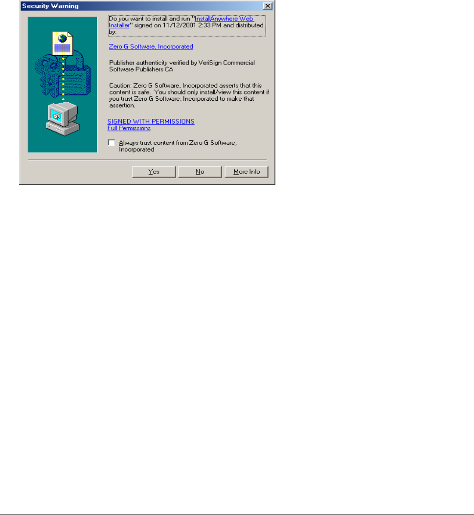
2. Double-click on the Install icon. Two windows open simultaneously: InstallAnywhere Web
Installer — Microsoft Internet Explorer (in disabled mode) superimposed by Security Warning
(in enabled mode).
Click the Yes button on the Security Warning window to close this window and view the Base Station
Configuration Software window.
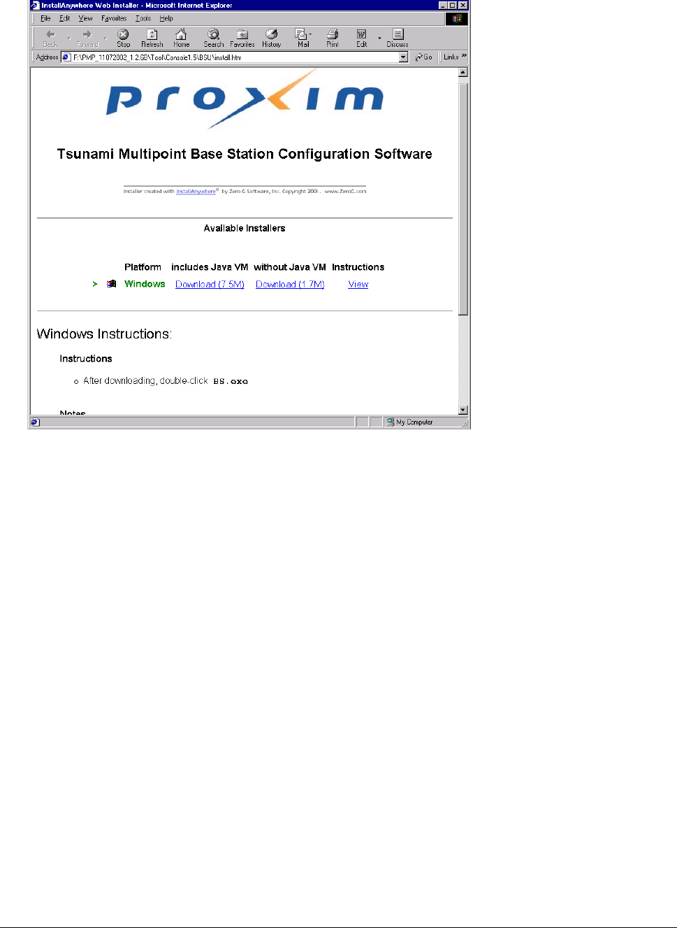
For the remainder of this procedure, only default settings are used. Select the applicable installer for
your network environment when performing these steps.
3. Click Download 7.5M to download the Tsunami Multipoint Base Station configuration software and
Java VM; click Download 1.7M to download the Tsunami Multipoint Base Station configuration
software without Java VM.
Appendix B. Installing the Software and Upgrading Firmware 52
CPN 63179 Issue Date: 01/24/03
Tsunami Multipoint Version 1.3 Installation Guide
After the download completes, double-click on BS.exe to begin installation.
When the Tsunami Multipoint Base Station Configuration Software Introduction window is
displayed; click Next.
4. Click Next on the Important Information window once you have completed reading the text. When
the License Agreement window is displayed, accept the terms of the License Agreement and click
Next to proceed with the installation.
5. Click the Next button after making your choices on the following windows:
º Choose Install Folder (you can select the default folder or specify another folder)
º Choose Java Virtual Machine (you can select the default machine or specify another machine)
º Pre-Installation Summary (summarizes the installation choices you have made)
6. When the Install Complete window is displayed, click on Done to return to the Web Installer
window; then close the Web Installer window.
Appendix B. Installing the Software and Upgrading Firmware 53
CPN 63179 Issue Date: 01/24/03

Tsunami Multipoint Version 1.3 Installation Guide
Subscriber Utility Software
System Requirements
Same as for Base Station Configuration Software (see “System Requirements” for the BSU on page 51).
Installing the Subscriber Utility Software
System requirements for the Subscriber Utility software are the same as for the Base Station
Configuration software.,
To install the utility software:
1. Identify the computer on which you plan to run the Subscriber Utility.
Note: See “System Requirements” for the BSU on page 51 for operating system and hardware requirements.
2. Insert the Tsunami MP CD (provided with the product) into the computer’s CD-ROM drive and open
the CD’s config software folder.
Note: If the computer has Microsoft IIS (Internet Information Services) running, disable or uninstall it before
running the Subscriber Utility.
3. Double-click SUSETUP.HTM or use a Web browser to open the file.
4. Place a checkmark next to the Include VM in download option to install Java Virtual Machine (VM).
Note: You need not add VM if your computer already has a version of VM installed.
5. Click the Start Installer for Windows button to begin the software installation.
6. Follow the on-screen instructions to install the software.
7. Click Done when the installation is finished to close the installer.
8. Launch the Subscriber Utility.
Firmware Downloads
Firmware can be downloaded to the BSU using the local console. Firmware can be downloaded to the SU
either over-the-air or from a local console (by attaching a PC with the Base Station Configuration
Software to the SU).
Proxim recommends you download new code as follows:
1. Download the new code to the SU’s and verify that they re-enter the network.
2. Next, download new code to the BSU.
Appendix B. Installing the Software and Upgrading Firmware 54
CPN 63179 Issue Date: 01/24/03

Tsunami Multipoint Version 1.3 Installation Guide
Remote Over-the-Air Download to SUs
You can upgrade your SUs to Version 1.3 from the Base Station Configuration Software Console of the
BSU. Normally, all SUs in the network are upgraded at the same time. However, if one or more SUs fail
to receive the download code correctly, the upgrade is aborted and a second attempt must be made. SUs
that have been upgraded successfully ignore reprogramming of the same codes.
To download remotely to SUs:
1. From the BSU 1.4 or 1.5 Console, confirm that SUs have established a link with the BSU by issuing a
dspActiveSU command. Make note of the SUs in the network.
2. Select the Download menu.
3. Select Remote Firmware; a Download — File Selection window is displayed.
4. From the Look In search field, select the binary file to be downloaded (PMP_SU_release1-3.mot)
from the appropriate directory. The BSU Console automatically processes the selected binary codes
and, once finished, displays an output of “Elapsed [time]” in seconds.
5. Let the SUs re-enter the network. It usually takes no more than five minutes for the SUs to enter the
network from the start of the download. The following messages are displayed at the BSU Console
for each SU as it enters the network:
º 118 Received NetEntry Request from Eth<SUs Ethernet address>
º 119 NetEntry completed: Assigned terminal ID <ID#>, IP<SUs IP address>, and VLAN ID
<SU VLAN ID#> in VLAN mode.
6. Issue dspActiveSU to verify that the SUs have entered the network successfully. If an SU fails to
enter the network, use the local download procedure in the following section.
º If the SU was correctly upgraded, the display reads ver 20021300.
º If the SU failed to upgrade and the link was restored, the display most likely reads ver
200212B0.
7. If any SU that re-entered the network failed to upgrade to Version 1.3, repeat steps 2 through 6, or
upgrade the failing SUs using the “Local Download to SUs” method.
Local Download to SUs
You can use this method to upgrade SUs that have not been deployed or have failed to successfully
download using the remote over-the-air procedure. Using this procedure, individual SUs are upgraded
through their Ethernet/Power cable. This procedure requires the Tsunami Multipoint Base Station
Configuration Software application be loaded on the PC attached to the SU (SU 1.,4 or 1.5 Console). The
window label appears as Tsunami Multipoint Subscriber Configuration Software.
Appendix B. Installing the Software and Upgrading Firmware 55
CPN 63179 Issue Date: 01/24/03