Proxim Wireless S58-B60 Tsunami Multipoint Base Station Unit User Manual Backing down from TNG CCI 2
Proxim Wireless Corporation Tsunami Multipoint Base Station Unit Backing down from TNG CCI 2
Contents
Installation manual part 4

Tsunami Multipoint Version 1.3 Installation Guide
Proxim recommends that you retain all the packaging materials (including all internal boxes). In the
unlikely event that the equipment must be returned to the factory, use the original packing materials for
return shipment. The packaging materials are also recommended for transporting the equipment from
location to location.
Mounting the Base Station Unit
You can mount the outdoor component of your Tsunami Multipoint Base Station Unit directly to a pole
with an outside diameter of 1- ½ to 4- ½ inches.
Mounting the BSU is essentially a two-step process:
1. Assemble the BSU’s mounting components on the ground (ground work).
2. Mount the BSU to a pole using the mounting components.
Tsunami Base Station Unit System
Title Part Number Quantity
BSU Installation Kit, consisting of the following:
CD-Tsunami Multipoint Base Station CD
Assembly Cable, WAC, Cat 5, 50 M
Contact Kit, Positronic
Contact Kit, AMP
Mounting hardware (see the following table)
58686
100-00844-02
100-00861-00
100-00862-00
1 each
1 each
1 each
1 each
1 set
BSU Mounting Hardware
Mounting Hardware Part Number Quantity
Mounting Bracket Galvanized (U-Shaped) 200-01114-00 2 each
Screw, 3/8-16 x 1” Full Thread, Hex Head, SS316 720-01130-00 4 each
Washer, Split Lock, # 3/8, SS 316 730-01131-00 4 each
Notched Bracket 200-01115-00 1 each
Bracket, Downtilt 200-01116-00 1 each
Screw, 3/8-16 x 1 ¼ Full Thread, Hex Head, Galvanized 720-01120-00 6 each
Washer, Split Lock, #3/8, Galvanized 730-01122-00 10 each
Lockwasher, Int. and Ext., #3/8, Galvanized 730-01123-00 2 each
Nut, Hex, 3/8-16, Galvanized 740-01125-00 10 each
Bracket, Clamp (M-Shaped) 200-01117-00 2 each
Strap, Clamp 200-01118-00 2 each
Screw, 3/8-16 x 1” Full Thread, Hex Head 720-01119-00 4 each
Screw, 2/1-13 x 7 ½ Full Thread, Hex Head, Galvanized 720-01121-00 4 each
Washer, Split Lock, #1/2, Galvanized 730-01124-00 4 each
Nut, Hex, ½-13, Galvanized 740-01126-00 8 each
Screw, Machine, SEM, #10-32 x 3/8, Int Star 720-00580-00 5 each
Bracket, GPS Antenna Mtg 200-01083-00 1 each
GPS Antenna, WAC Transceiver 100-00754-00 1 each
Clamp, Band, 2” – 5” Diameter, SS Quick Rel 720-01127-00 1 each
Chapter 2. Pre-Installation Tasks 17
CPN 63179 Issue Date: 01/24/03
Tsunami Multipoint Version 1.3 Installation Guide
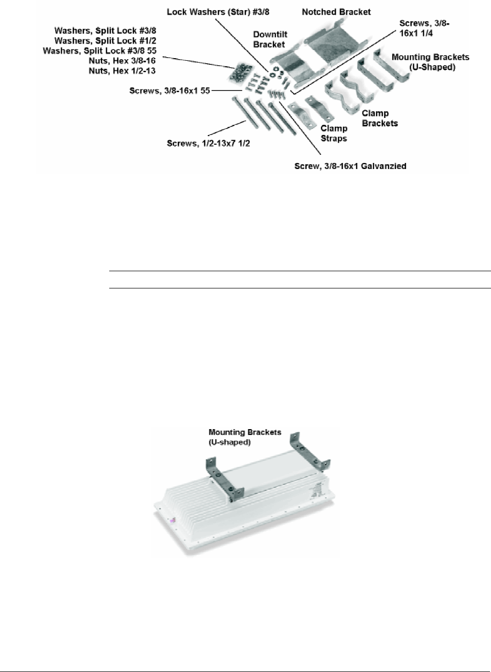
Figure 7. BSU Mounting Hardware
Required Tools: 9/16” (14-23 mm) wrench
6” (155 mm) crescent wrench
Note: Torque all #3/8 bolts and nuts 250 ± 10 in-lbs.
BSU Mounting: Ground Work
To assemble the BSU’s mounting components:
1. Place the BSU face (transmitter side) down on a flat surface.
2. Attach the two (u-shaped) galvanized mounting brackets to the back of the BSU using the four
stainless steel 3/8-16, hex head screws and four #3/8 split lock washers (see the following photo).
Figure 8. U-Shaped Mounting Brackets Attached
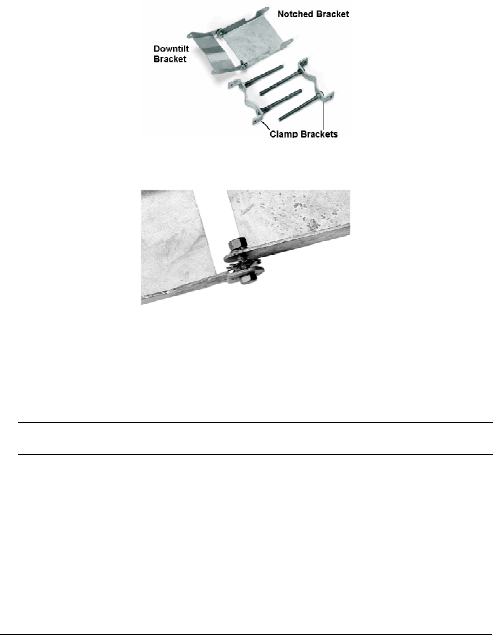
3. Insert two 1/2-13x7 1/2 screws through one of the clamp brackets (m-shaped) and secure the bolts
using two 1/2-13 hex nuts. Repeat this step for the other set of 1/2-13x7 1/2 screws, clamp bracket,
and 1/2-13 hex nuts (see Figure 9).
Chapter 2. Pre-Installation Tasks 18
CPN 63179 Issue Date: 01/24/03
Tsunami Multipoint Version 1.3 Installation Guide
4. Connect the downtilt bracket to the notched bracket using two 3/8-16x1 1/4 hex head screws, #3/8
split lock washers, #3/8 (star) lock washers, and 3/8-16 hex nuts (see Figure 9).
Figure 9. Downtilt and Clamp Brackets with Screws Attached
Figure 10. Bracket Assembly Detail of Screw, Washers, and Nut
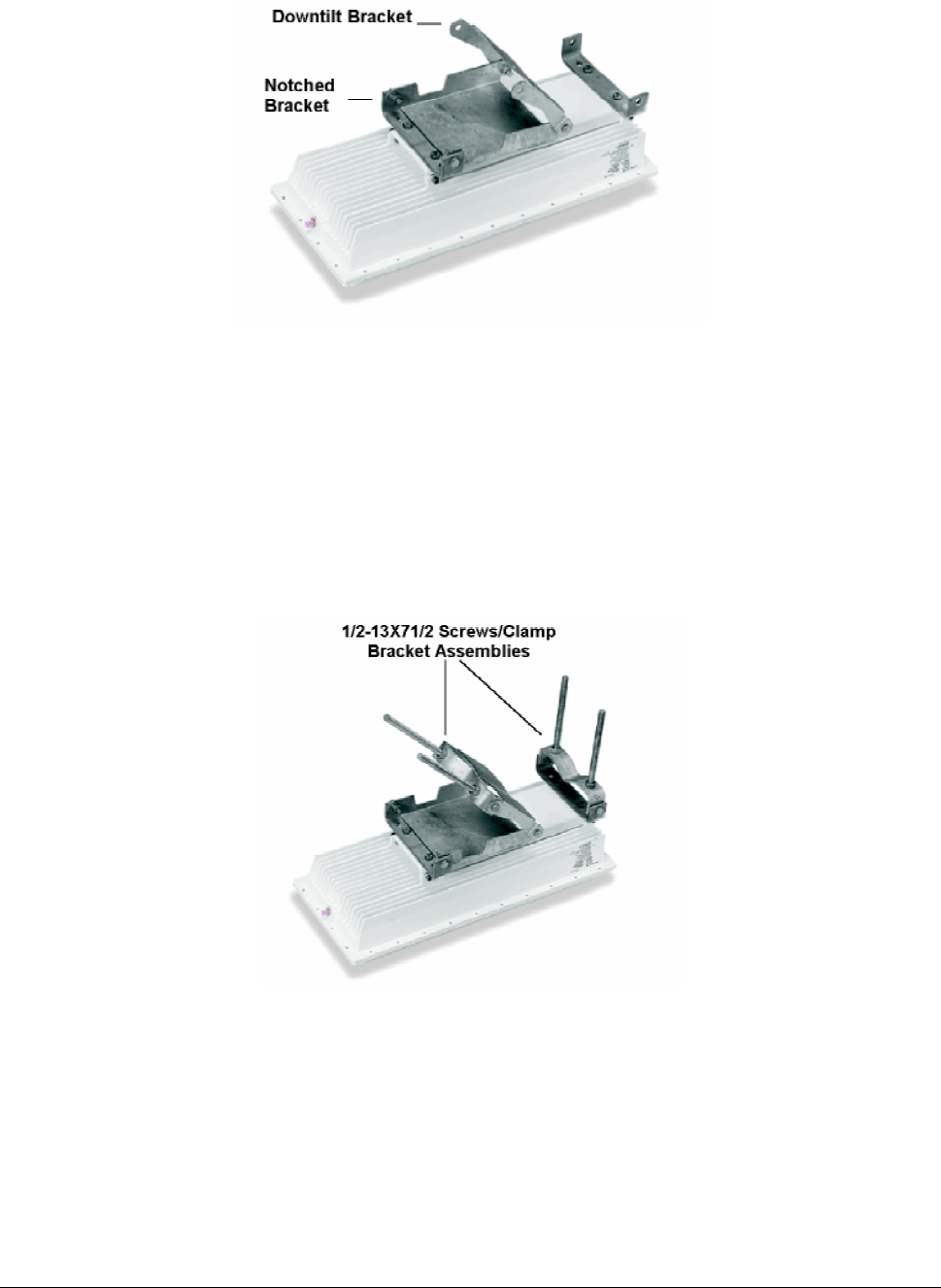
5. Attach the downtilt/notched bracket assembly to the u-shaped mounting bracket near the middle of
the BSU using two sets of 3/8-16x1 1/4 hex head screws, #3/8 split lock washers, and 3/8-16 nuts.
Note: This mounting method lets you point the BSU down when mounted on a pole; to point the BSU up, attach
the downtilt/notched bracket assembly to the u-shaped mounting bracket near the bottom of the BSU.
Chapter 2. Pre-Installation Tasks 19
CPN 63179 Issue Date: 01/24/03
Tsunami Multipoint Version 1.3 Installation Guide
Figure 11. Bracket Assembly Attached to Mounting Bracket
6. Attach one of the 1/2-13x7 1/2 screws/clamp bracket assemblies to the u-shaped mounting bracket
near the end of the BSU using two sets of 3/8-16x1 1/4 hex head screws, #3/8 split lock washers,
and 3/8-16 hex nuts (see Figure 12). (In this configuration, the BSU points down when mounted on a
pole.)
7. Attach the other 1/2-13x7 1/2 screws/clamp bracket assembly to the downtilt bracket using two sets
of 3/8-16x1 1/4 hex head screws, #3/8 split lock washers, and 3/8-16 hex nuts (see Figure 12).
Figure 12. Screws/Clamp Bracket Assemblies Attached
Chapter 2. Pre-Installation Tasks 20
CPN 63179 Issue Date: 01/24/03
Tsunami Multipoint Version 1.3 Installation Guide
Mounting the BSU to a Pole
To mount the BSU to a pole using the attached mounting components:
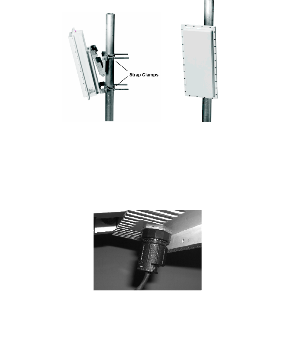
1. Lash the unit to the pole or use a hoisting rope to keep the unit in place while you mount it. Slide the
two strap clamps over the two sets of 1/2-13x7 1/2 screws and secure the strap clamps using four
#1/2 split lock washers and four 1/2-13 hex nuts (see the following photo).
Figure 13. Strap Clamps Attached and Mounted BSU
2. To adjust the up/down tilt (-10 to +5 degrees), move the top or bottom of the BSU (depending on
how you installed the downtilt/notched bracket assemblies) until the unit is roughly positioned at the
correct angle.
3. Connect the supplied Cat 5 cable to the BSU’s Power and Ethernet port as described in the following
notes. Then screw on the outer ring to secure the cable in place.
Figure 14. BSU’s Power and Ethernet Connector
Chapter 2. Pre-Installation Tasks 21
CPN 63179 Issue Date: 01/24/03
Tsunami Multipoint Version 1.3 Installation Guide
The Base Station Unit (BSU) is shipped with a dust cover over the large 18-pin connector. Keep
this cover on until ready to mate with cable connector to avoid getting the connector wet.
To ensure proper weatherproofing, follow these procedures to connect the supplied Cat 5 cable
to the BSU’s Power and Ethernet port.
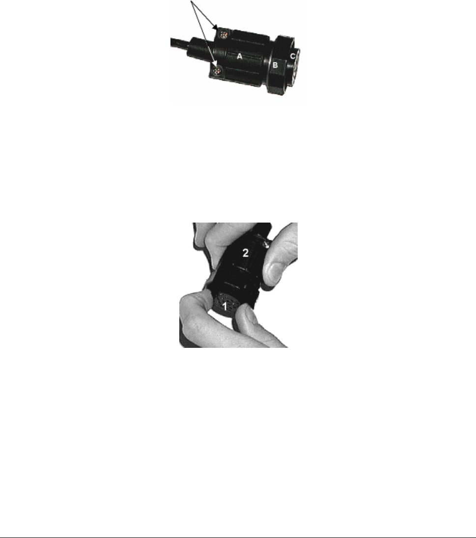
A. Check the BSU connector. The only moving part should be the plastic nut (“B”), which screws
onto the BSU housing.
B. If there is any movement or play between parts A and C, you must tighten these parts before
proceeding; otherwise you could cause connector pins to disconnect or break when you apply
the weatherproofing tape. To tighten, first loosen (but do not remove) the connector’s
screws (indicated with arrows in the previous figure).
C. Then, while holding the pin connection portion (1), turn the bottom portion (2) clockwise until
there is no more movement, making sure you do not over-tighten.
D. Re-tighten the screws.
E. When mating the BSU to the cable connector, first apply a bead of silicone grease or RTV to
the 3mm-wide outward-most flange on the BSU connector (or in the outer ring of the cable-
end mating connector).
F. Then tighten the plastic nut on the cable end to 16 inch-lbs (1.81 N-m). The cable connector
must be tightened onto the BSU sufficiently to compress a small O-ring that resides inside the
male BSU connector. If the O-ring is missing or insufficiently compressed, moisture can get
through into the connector pins.
Chapter 2. Pre-Installation Tasks 22
CPN 63179 Issue Date: 01/24/03
Tsunami Multipoint Version 1.3 Installation Guide
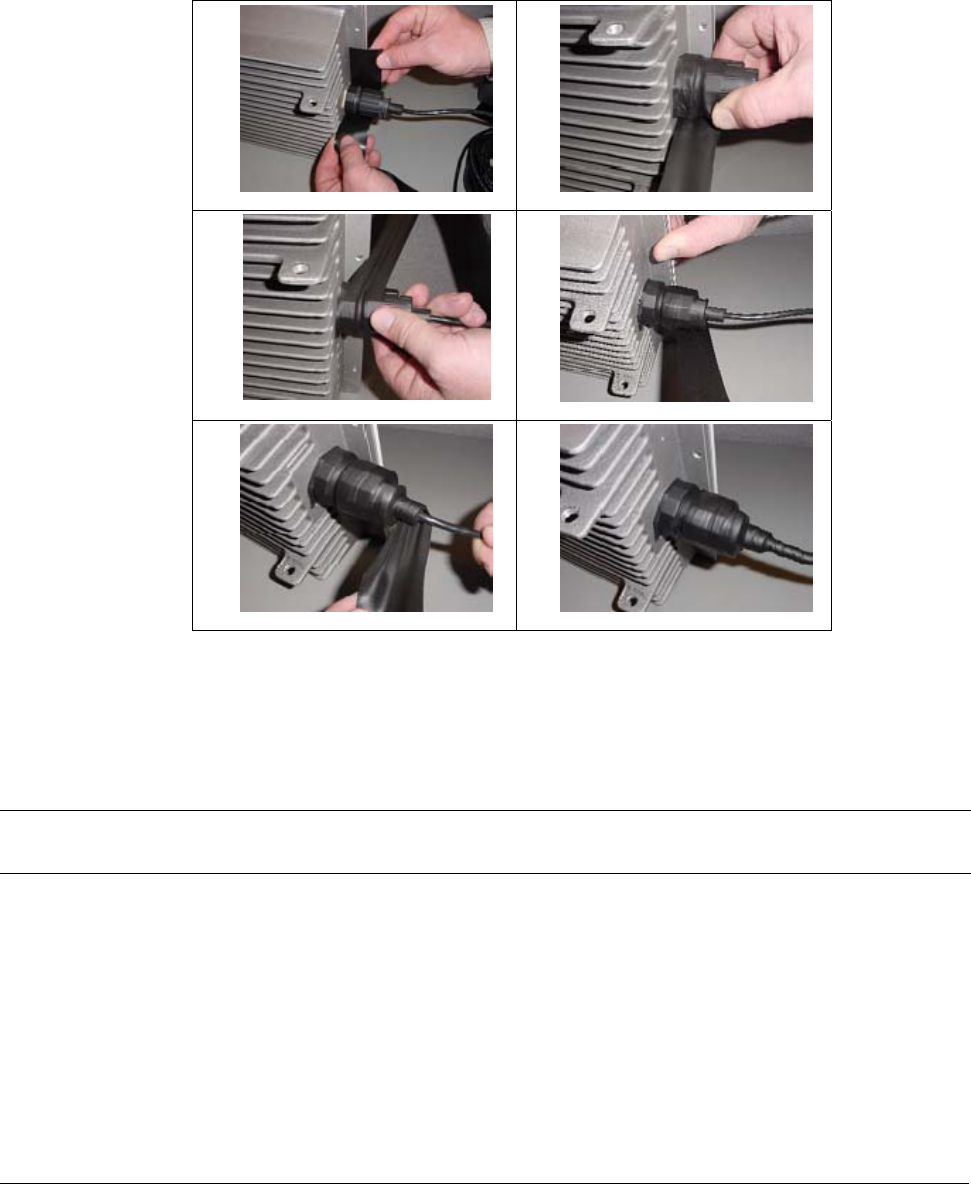
Once mated, over-wrap the connectors (as demonstrated in the following table) with stretchy
black self amalgamating tape (such as CTB-15 CATV TAPE-X5-BK-UN part #22150000 from
DSG – CANUSA 173, Commerce Boulevard, Loveland, Ohio 45140, Tel. 1-800-422-6872) to
ensure a better water seal.
1) 2)
3) 4)
5) 6)
4. Connect the other end of the Cat 5 cable to the BSU’s power supply. (The BSU’s power supply is
ordered and shipped separately. The power supply’s CPN number is 58526.)
5. Plug the power supply into an electrical outlet.
Note: To ensure proper grounding, use the hole on the back of the BSU and the provided grounding screw to attach
a ground wire to the BSU. Use wire grounding techniques in accordance with your local electrical codes.
Chapter 2. Pre-Installation Tasks 23
CPN 63179 Issue Date: 01/24/03
Tsunami Multipoint Version 1.3 Installation Guide
Installing the GPS Antenna
If you do not plan to install multiple BSU in the same geographical area skip this section
If you plan to install multiple BSUs in the same geographical area (for example, one BSU might interfere
with another), you must install the supplied GPS antenna (a small metal plate with a black 2"x 2"
antenna and thin cable) on each BSU. Each BSU uses a global positioning system (GPS) to synchronize
its clock with other BSUs. You also must set each BSU to Multi Sector mode (see “Configuring the
System for Multi-Sector Mode” on page 29).
Mounting the GPS Antenna
To install the GPS antenna:
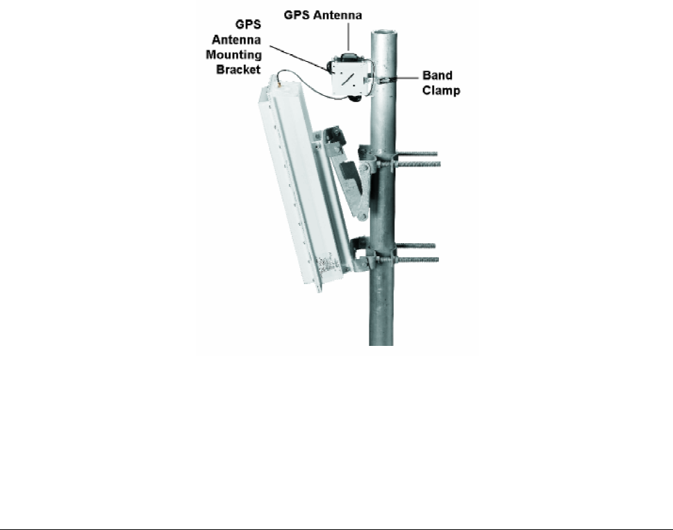
1. Position the GPS antenna in a location where the antenna plate is parallel to the earth/horizon and
the black antenna bump-up can be attached to the BSU (as shown in the following figure). The GPS
antenna should be exposed to as much of the sky as possible so it can acquire at least four GPS
satellites to extract timing signals for the BSU transmission synchronization.
Figure 15. GPS Antenna Mounted on BSU
2. Insert the band clamp through the slots in the GPS antenna-unit mounting bracket and around the
mounting pole. Tighten the clamp around the mounting pole and then tighten the screw in the clamp
to secure the GPS antenna mounting bracket to the mounting pole.
3. Attach the GPS antenna to the GPS antenna mounting bracket using the #10-32x3/8 SEM screws
(the screws with attached washers).
Chapter 2. Pre-Installation Tasks 24
CPN 63179 Issue Date: 01/24/03

Tsunami Multipoint Version 1.3 Installation Guide
4. Remove the water-protection cap from the top of the BSU and screw on the cable from the GPS
antenna to the connector on the top of the BSU.
Installing BSU Configuration Software
The next step is to configure the BSU. The BSU is configured from a PC running the BSU Configuration
Software (Versions 1.4 or 1.5). This PC communicates with the BSU through its Ethernet port. If you
have a PC with the BSU Configuration Software already installed, skip to “Configuring the Base Station”
on page 26; otherwise, install the BSU Configuration software as described in “Appendix B. Installing the
Software and Upgrading Firmware” on page 51.
Operating in a Test Environment
Prior to installation outdoors, you may want to operate the equipment indoors in a test environment to
become familiar with the operating configurations and performance. Furthermore, in situations in which
it is extremely difficult (very low temperature) or costly (on a mountain top) to install or replace the
equipment, you may want to verify operation in an indoor test environment prior to actual installation in
the field. All of the configuration and testing information described in the previous chapters, with the
exception of the actual mounting of the units, apply to an indoor test deployment. The following sections
describe a procedure to set up a pre-installation testing environment for this purpose.
Warnings and Considerations for an Indoor Deployment
Review the following important warnings and considerations before turning on any Tsunami Multipoint
equipment indoors in your test environment.
WARNING! All persons should be at least 5 feet (1.5 meters) away from any antenna when any products
are operational.
Place the antennas at least 30 feet apart, facing each other.
▪ To minimize the multi-path phenomenon, the BSU should be configured to use the lowest transmit
power level (6 dBm) and the most reliable modulation technique (20 Mbps mode). In addition, the
BSU must have GPS and Range Security disabled. Also, make sure the BSU is facing toward the SU.
▪ Do not set up your laptop between the antennas or stand between the antennas.
▪ Try to minimize the movement of objects within the test environment to prevent changes in radio
propagation patterns. Radio signals behave differently indoors than outdoors; using the devices
indoors may have an unintended, negative effect on the performance of the Tsunami Multipoint
system.
▪ For best results, connect at least one computer to the BSU and to each SU.
Chapter 2. Pre-Installation Tasks 25
CPN 63179 Issue Date: 01/24/03