Psion 7527SBTRA2041M Workabout Pro G2 User Manual 7535 G2 Hand Held Computer
Psion Inc Workabout Pro G2 7535 G2 Hand Held Computer
Psion >
Contents
- 1. Users Manual
- 2. User Manual Part 1
- 3. User Manual Part 2
- 4. User Manual Part 3
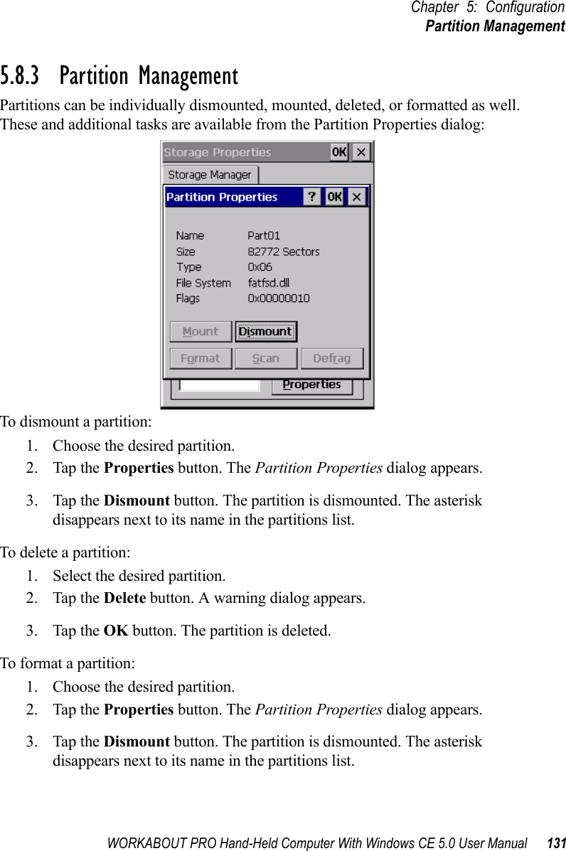
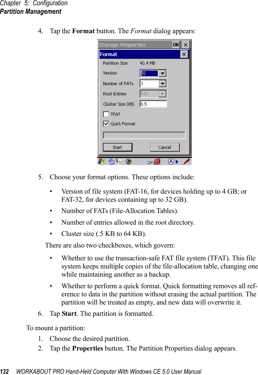
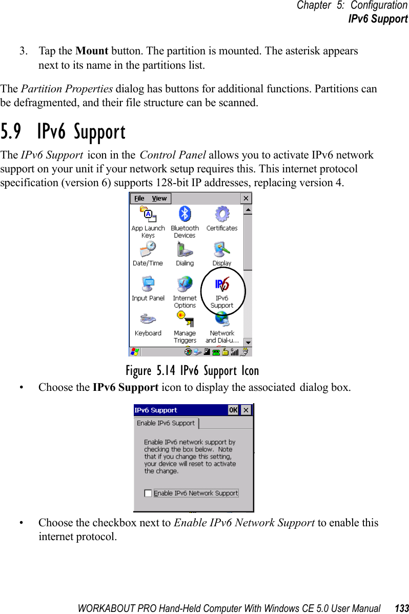
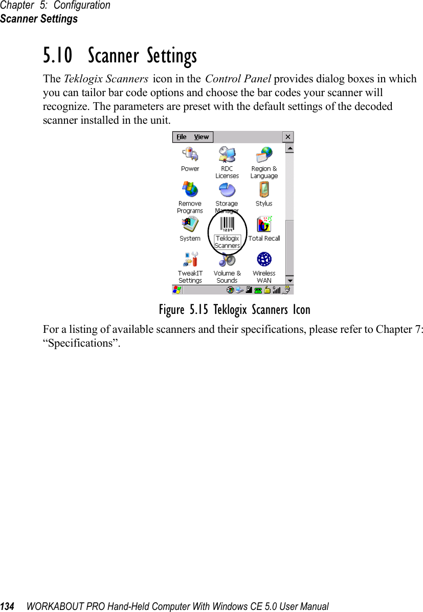
User Manual Part 2
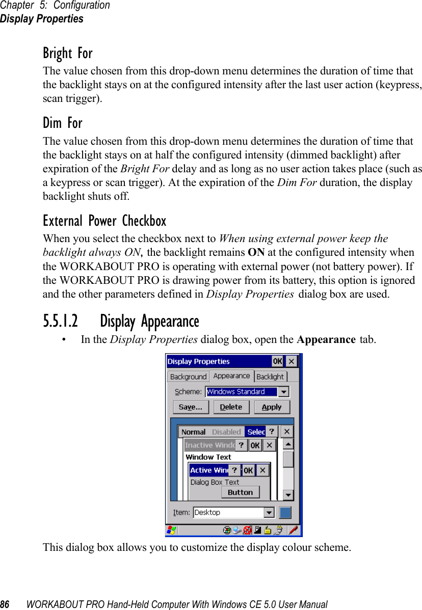
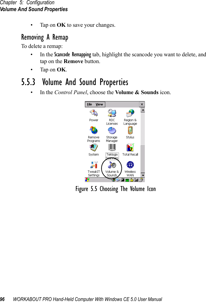
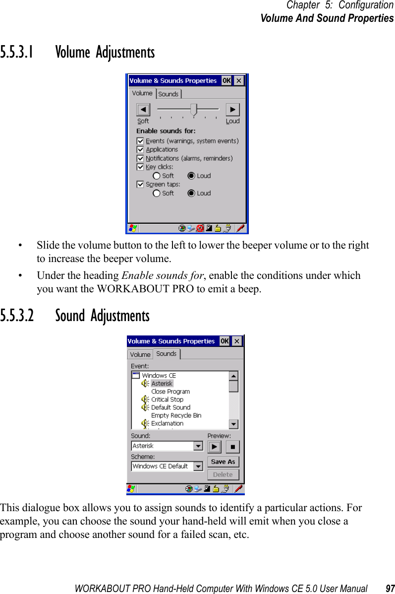
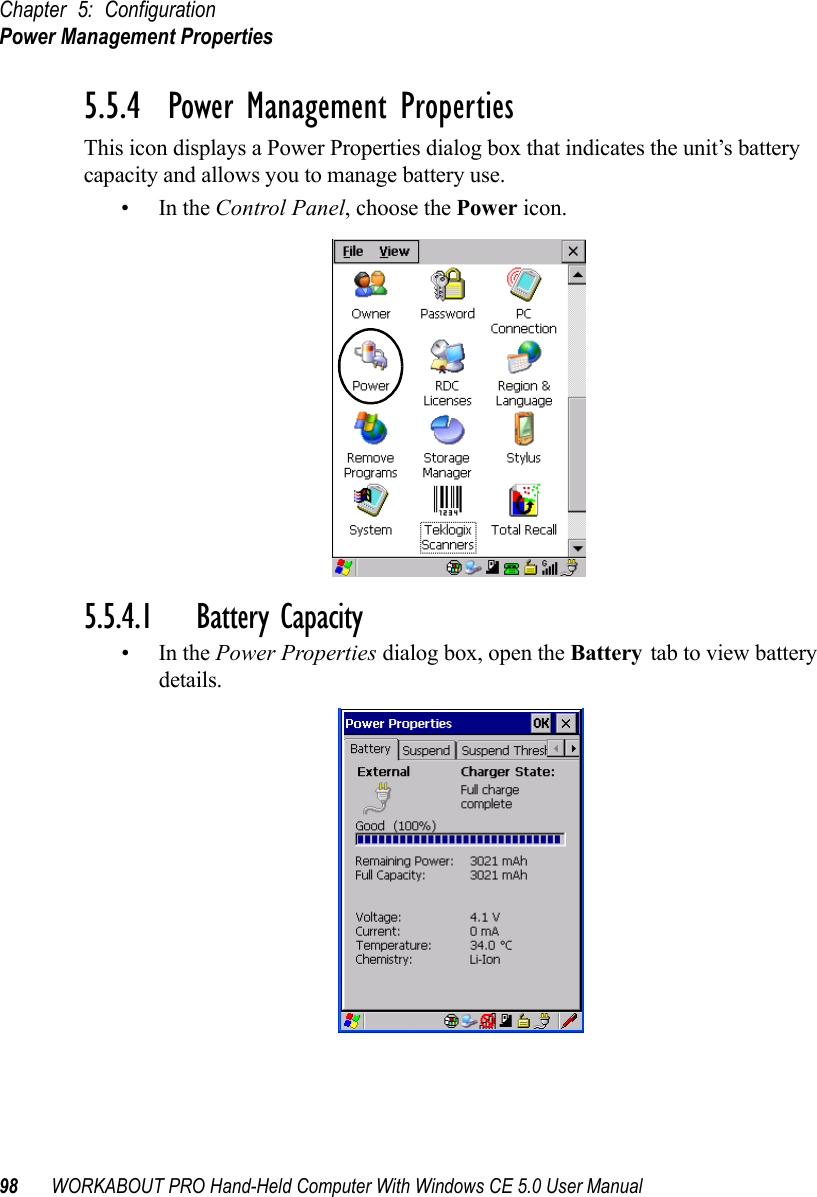
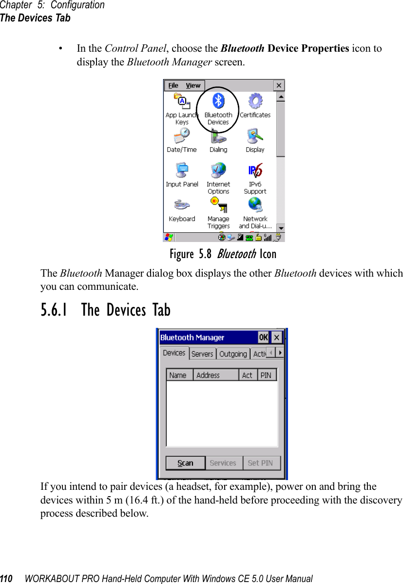
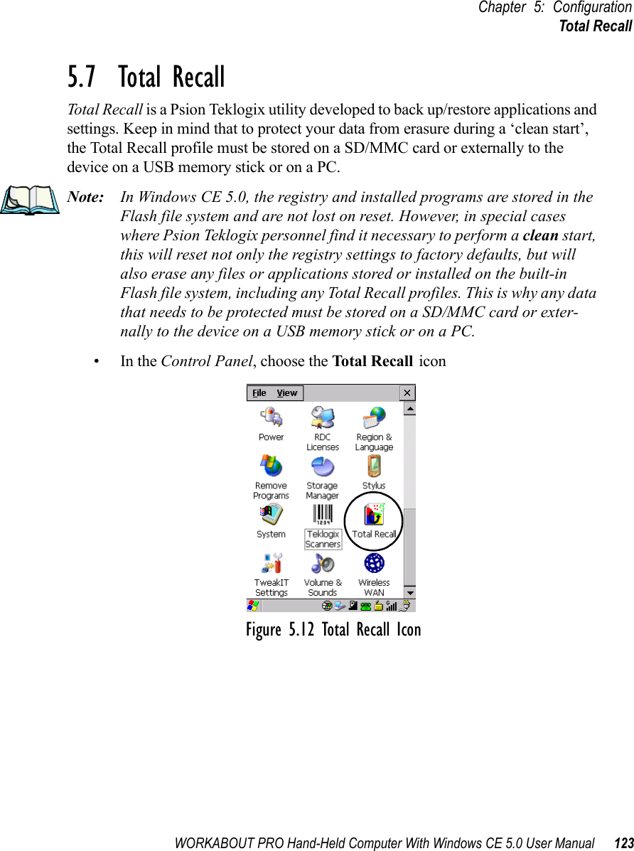
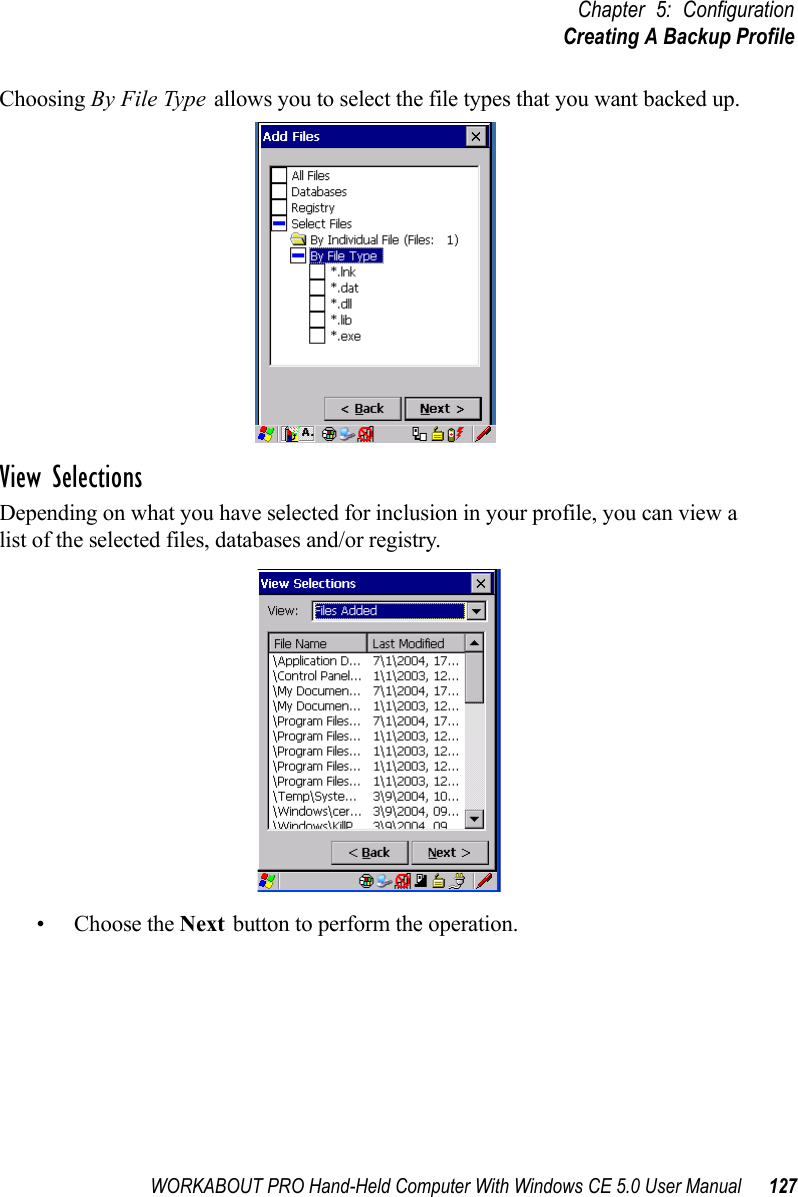
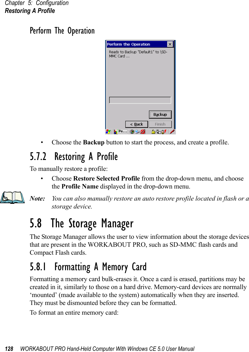
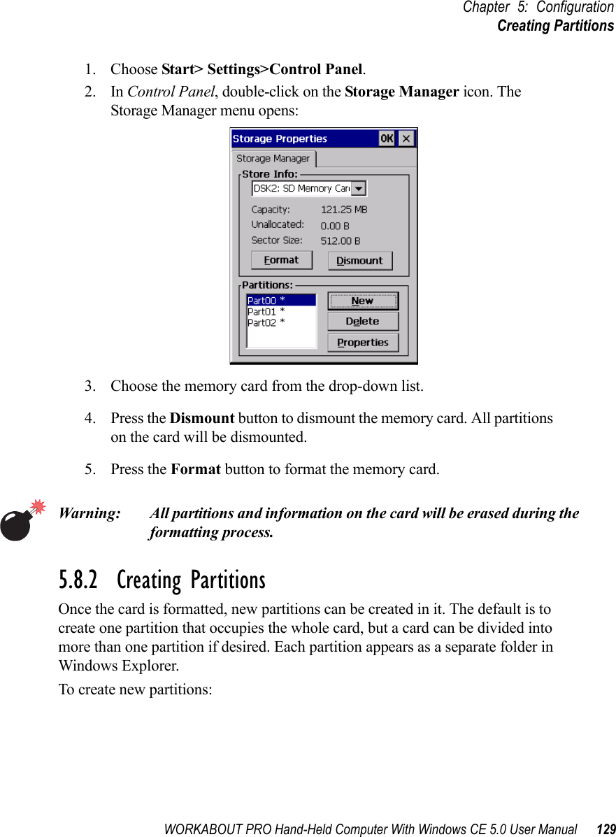
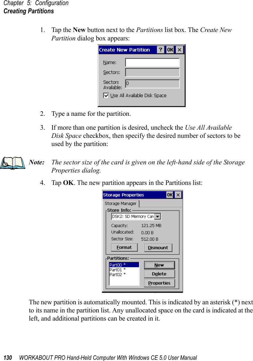
![WORKABOUT PRO Hand-Held Computer With Windows CE 5.0 User Manual 79Chapter 5: ConfigurationRemote Connect5.1 Remote Connect Remote Connect is a WORKABOUT PRO application used to connect to a Windows Terminal Server so that you can run a “session” on the Server machine, using the WORKABOUT PRO (Windows CE 5.0 device). Refer to the following website for step-by-step information about setting up this connection: http://www.microsoft.com/WindowsXP/pro/using/howto/gomobile/remotedesktop/default.aspor contact Psion Teklogix support services. (Refer to WORKABOUT PRO Hand-Held Computer Regulatory & Warranty Guide, PN 8000126, or locate the office closest to you at www.psionteklogix.com).5.2 The TekTerm ApplicationTekTerm is a powerful emulation application ideally suited for real time data transaction applications associated with mainframes and servers. The WORKABOUT PRO includes unique features that support TekTerm—a Psion Teklogix application that has the ability to maintain multiple simultaneous sessions with a variety of host computers. For detailed information, please refer to the TekTerm Software User Manual, PN 8000073.5.3 The Control PanelThe Windows CE 5.0 Control Panel provides a group of icons through which you can set a variety of system-wide properties, such as mouse sensitivity, network configuration and the desktop color scheme.Note: If you are uncertain how to move around a dialog box and make selec-tions, review “Using A Dialog Box” on page 71.When the WORKABOUT PRO boots up, the startup desktop (shell) is displayed, and any applications stored in the Startup folder start up immediately. To access the Control Panel:• Tap on Start>Settings>Control Panel.If you’re using the keyboard:• Press [FN/BLUE] [.] to display the Start Menu.• Highlight Settings in Start Menu, and press the [RIGHT] arrow key to highlight the Control Panel.](https://usermanual.wiki/Psion/7527SBTRA2041M.User-Manual-Part-2/User-Guide-851397-Page-4.png)
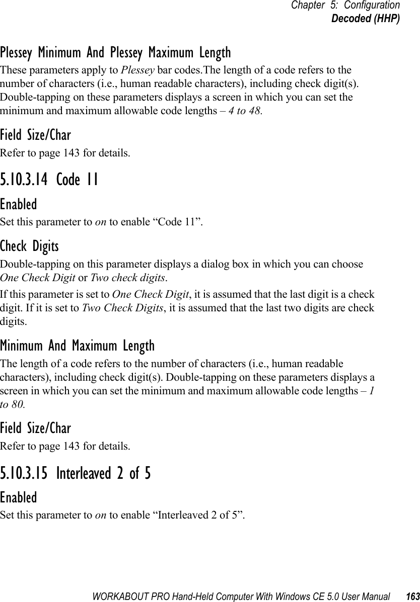
![Chapter 5: ConfigurationControl Panel Icons80 WORKABOUT PRO Hand-Held Computer With Windows CE 5.0 User Manual• Press the [ENTER] key.The Control Panel folder contains icons used in the setup of your WORKABOUT PRO.Figure 5.1 Control Panel5.4 Control Panel IconsThe Control Panel provides a group of icons that allow you to customize and adjust settings on your WORKABOUT PRO.App Launch KeysBy mapping keys to applications using this program, you can then launch those applications from a single key-press.Bluetooth DevicesProvides the tools to manage device pairing and configuration.](https://usermanual.wiki/Psion/7527SBTRA2041M.User-Manual-Part-2/User-Guide-851397-Page-5.png)
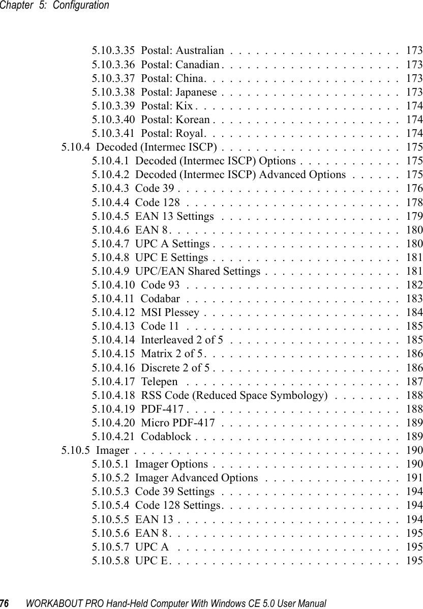
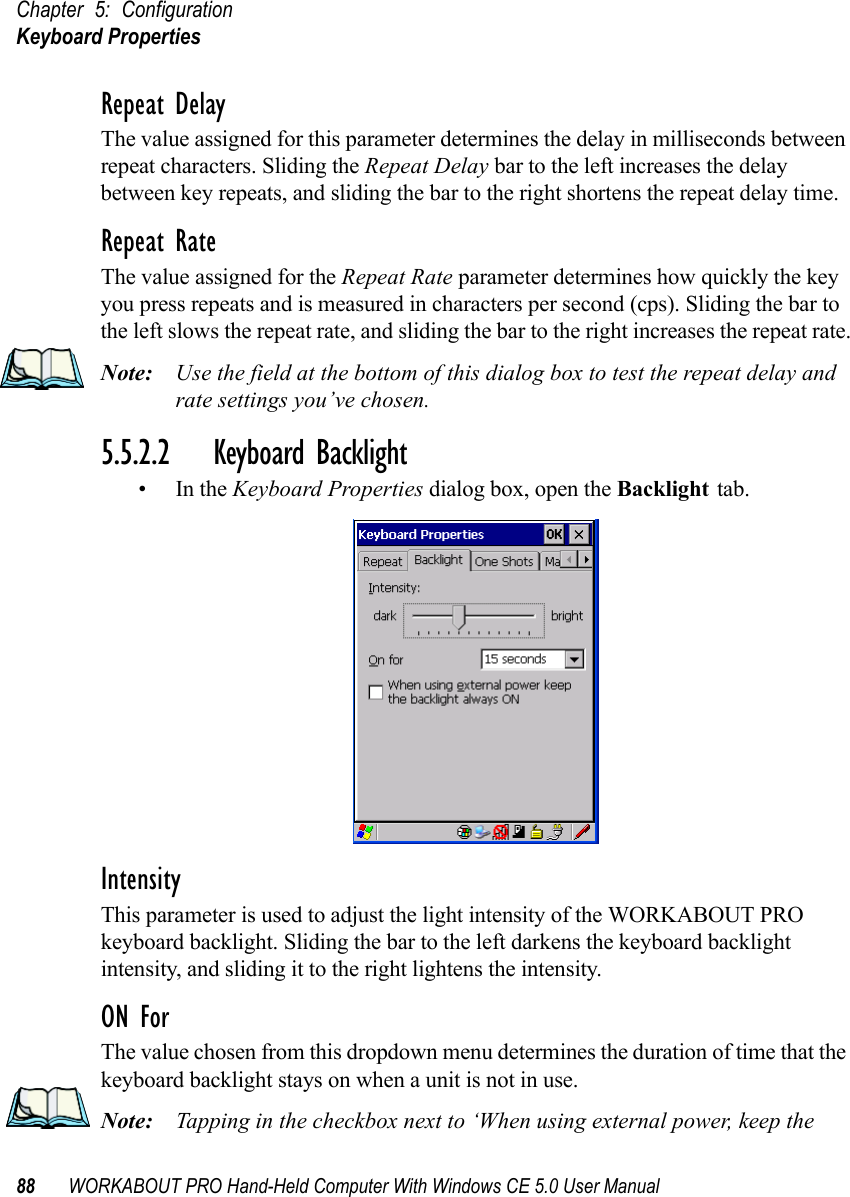
![WORKABOUT PRO Hand-Held Computer With Windows CE 5.0 User Manual 87Chapter 5: ConfigurationKeyboard Properties5.5.2 Keyboard PropertiesThis icon displays the Keyboard Properties dialog box in which you can adjust the repeat rate of the keys, the intensity of the keyboard backlight and the behaviour of the [FN/BLUE] and [ORANGE] modifier keys. This dialog box also allows you to define macro keys and Unicode characters.•In the Control Panel, choose the Keyboard icon.Figure 5.3 Choosing The Keyboard Icon5.5.2.1 Key RepeatNote: These settings apply when a key is held down continuously. •In the Keyboard Properties dialog box, open the Repeat tab.](https://usermanual.wiki/Psion/7527SBTRA2041M.User-Manual-Part-2/User-Guide-851397-Page-11.png)
![WORKABOUT PRO Hand-Held Computer With Windows CE 5.0 User Manual 89Chapter 5: ConfigurationKeyboard Propertiesbacklight always ON’ forces the keypad backlight to remain on when the unit is operating with external power.5.5.2.3 Keyboard One Shot Modes• In the Keyboard Properties dialog box, open the One Shots tab.The options in this tab allow you to determine how modifier keys on your WORKABOUT PRO behave. For each modifier key—[ALT], [SHIFT], [CTRL], [FN/ORANGE] and [FN/BLUE]—you have the following options in the drop-down menu: Lock, OneShot, and OneShot/Lock. Note: Keep in mind that checking the taskbar lets you know whether or not these keys are locked on. For example, if the [FN/ORANGE] key is locked ‘on’, the taskbar at the bottom of the screen displays it in uppercase char-acters, ORANGE KEY. If this key is displayed in lowercase characters in the taskbar, you’ll know that the orange key is not locked. It will become inac-tive following a key press.Important: Once you’ve assigned a One Shot mode to a modifier key, you need to tap on the OK button at the top of the tab to activate your selec-tion.LockIf you choose Lock from the drop-down menu, pressing a modifier key once locks it ‘on’ until you press the modifier key a second time to unlock or turn it off.](https://usermanual.wiki/Psion/7527SBTRA2041M.User-Manual-Part-2/User-Guide-851397-Page-13.png)
![Chapter 5: ConfigurationKeyboard Properties90 WORKABOUT PRO Hand-Held Computer With Windows CE 5.0 User ManualOneShotIf you choose OneShot, the modifier key remains active only until the next key is pressed.OneShot/LockOneShot/Lock allows you to combine these functions. When you choose this option and you press the modifier key once, it remains active only until the next key is pressed. If you press the modifier key twice, it is locked ‘on’, remaining active until the modifier key is pressed a third time to turn it ‘off’.5.5.2.4 Keyboard Macro Keys•In the Keyboard Properties dialog box, open the Macros tab.A macro has 200 programmable characters (or “positions”). The macro keys can be programmed to replace frequently used keystrokes, along with the function of executable keys including [ENTER], [BKSP] and [DEL] ([FN/BLUE]-[BKSP]), function keys and arrow keys.Recording And Saving A MacroYou can program up to 12 macro keys on a 58-key WORKABOUT PRO. On a 36-key WORKABOUT PRO, you can program a maximum of 6 macro keys.•In the Macro menu highlight a macro key number, for example macro 1, to assign a macro to macro key [M1]. Choose the Record button.](https://usermanual.wiki/Psion/7527SBTRA2041M.User-Manual-Part-2/User-Guide-851397-Page-14.png)
![WORKABOUT PRO Hand-Held Computer With Windows CE 5.0 User Manual 91Chapter 5: ConfigurationKeyboard PropertiesA message screen is displayed instructing you to Enter Key Strokes to Record• Type the macro sequence you want to assign to the Macro key. You can type text and numbers, and you can program the function of special keys into a macro.• When you’ve finished recording your macro sequence, press the key sequence: [CTRL] [ALT] [ENTER], or choose the Stop Recording button.A new screen called ‘Verify Macro’ displays the macro sequence you created. The Save button is highlighted. • Press [ENTER] to save your macro, or highlight CANCEL and press [ENTER] to discard it.Executing A MacroTo execute a macro:• Press the macro key to which you’ve assigned the macro. For example, if you created a macro for macro key 1, press [M1] to execute the macro.Deleting A MacroTo delete a macro:•In the Macros tab, highlight the macro number you want to delete.• Choose the Delete button.](https://usermanual.wiki/Psion/7527SBTRA2041M.User-Manual-Part-2/User-Guide-851397-Page-15.png)
![Chapter 5: ConfigurationKeyboard Properties92 WORKABOUT PRO Hand-Held Computer With Windows CE 5.0 User Manual5.5.2.5 Unicode Mapping•In the Keyboard Properties dialog box, open the Unicode Mapping tab.The Unicode Mapping tab is used to map combinations of virtual key values and [CTRL] and [SHIFT] states to Unicode™ values. This tab shows the configured Unicode character along with the Unicode value. For example, the sample screen above shows “a (U+0061)” indicating that the character “a” is represented by the Unicode value “0061”, and so on. Keep in mind that Unicode configurations are represented as hexadecimal rather than decimal values.All user-defined Unicode mappings are listed in the Unicode Mapping tab in order of virtual key value, and then by order of the shift state. If a Unicode mapping is not listed, the Unicode mapping is mapped to the default Unicode value.Adding And Changing Unicode ValuesImportant: Changes to Unicode mappings are not saved until you exit the Keyboard Properties dialog box.](https://usermanual.wiki/Psion/7527SBTRA2041M.User-Manual-Part-2/User-Guide-851397-Page-16.png)
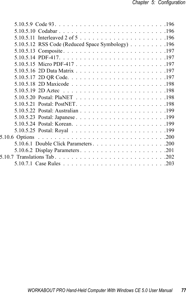
![WORKABOUT PRO Hand-Held Computer With Windows CE 5.0 User Manual 93Chapter 5: ConfigurationKeyboard Properties• Choose the Add/Change button.Figure 5.4 Adding And Change Unicode Values• Highlight a value in the Unicode mapping list. In the sample screen above, a value will be assigned to virtual key 0 (VK 0).• Position the cursor in the Unicode Mapping field, and type a Unicode value for the highlighted key.Note: To add a shifted state, [SHIFT] and/or [CTRL], press [TAB] to position the cursor in the checkbox next to ‘SHIFT Pressed’ and/or ‘CTRL Pressed’. Press [SPACE] to select the shift state you want to assign.Removing Unicode Values•In the Unicode Mapping tab, highlight the item you want to delete, and choose the Remove button.5.5.2.6 Scancode RemappingA scancode is a number that is associated with a physical key on a keyboard. Every key has a unique scancode that is mapped to a virtual key, a function or a macro. Scancode Remapping allows you to change the functionality of any key on the keyboard. A key can be remapped to send a virtual key (e.g. VK_F represents the ‘F’ key; VK_RETURN represents the [ENTER] key, etc.), perform a function (e.g. turn the scanner on, change volume/contrast, etc.) or run a macro.](https://usermanual.wiki/Psion/7527SBTRA2041M.User-Manual-Part-2/User-Guide-851397-Page-17.png)
![Chapter 5: ConfigurationKeyboard Properties94 WORKABOUT PRO Hand-Held Computer With Windows CE 5.0 User ManualThere are three different tables of scancode mappings: the Normal table, the Blue table and the Orange table. The Normal table defines unmodified key presses; the Blue table defines key presses that occur when the [FN/BLUE] modifier is on; the Orange table defines key presses that occur when the [FN/ORANGE] modifier is on. The default mappings of these scancodes can be overwritten for each of these three tables using the Scancode Remapping tab accessed from the Keyboard Properties dialog box.The first column in the Scancode Remapping tab displays the scancodes in hexadecimal. If the scancode is remapped to a virtual key, that virtual key is displayed in the next column labelled ‘V-Key’. A virtual key that is ‘Shifted’ or ‘Unshifted’ is displayed in the third column labelled ‘Function’. If the scancode is remapped to a function or a macro, the first and second columns remain blank while the third column contains the function name or macro key number (e.g., Macro 2).Adding A RemapTo add a new remapping:• Choose the Add button at the bottom of the dialog box.](https://usermanual.wiki/Psion/7527SBTRA2041M.User-Manual-Part-2/User-Guide-851397-Page-18.png)
![WORKABOUT PRO Hand-Held Computer With Windows CE 5.0 User Manual 95Chapter 5: ConfigurationKeyboard PropertiesThe Remap Scancode dialog box is displayed.• Type the scan code in hexadecimal in the field labelled ScancodeNote: The Label field displays the default function of the scancode you are remapping.Virtual Key, Function And MacroThe radio buttons at the bottom of the dialog box allow you to define to what the scan code will be remapped: Virtual Key, Function or Macro. When Virtual Key is selected, you can choose to force [SHIFT] to be on or off when the virtual key is sent. If No Force is selected, the shift state is dependent on whether the shift state is on or off at the time the virtual key is sent.When Function is selected, a list of valid functions appears in the dialog box. When Macro is selected, the macro keys available on your unit are listed in the dialog box.• Choose Virtual Key, Function or Macro.• Choose a function from the Function list in the dialog box, and tap on OK.Editing A Scancode RemapTo edit a scancode:•In the Scancode Remapping tab, tap the stylus on the remap you wantto edit.• Tap on the Edit button, and make the appropriate changes.](https://usermanual.wiki/Psion/7527SBTRA2041M.User-Manual-Part-2/User-Guide-851397-Page-19.png)
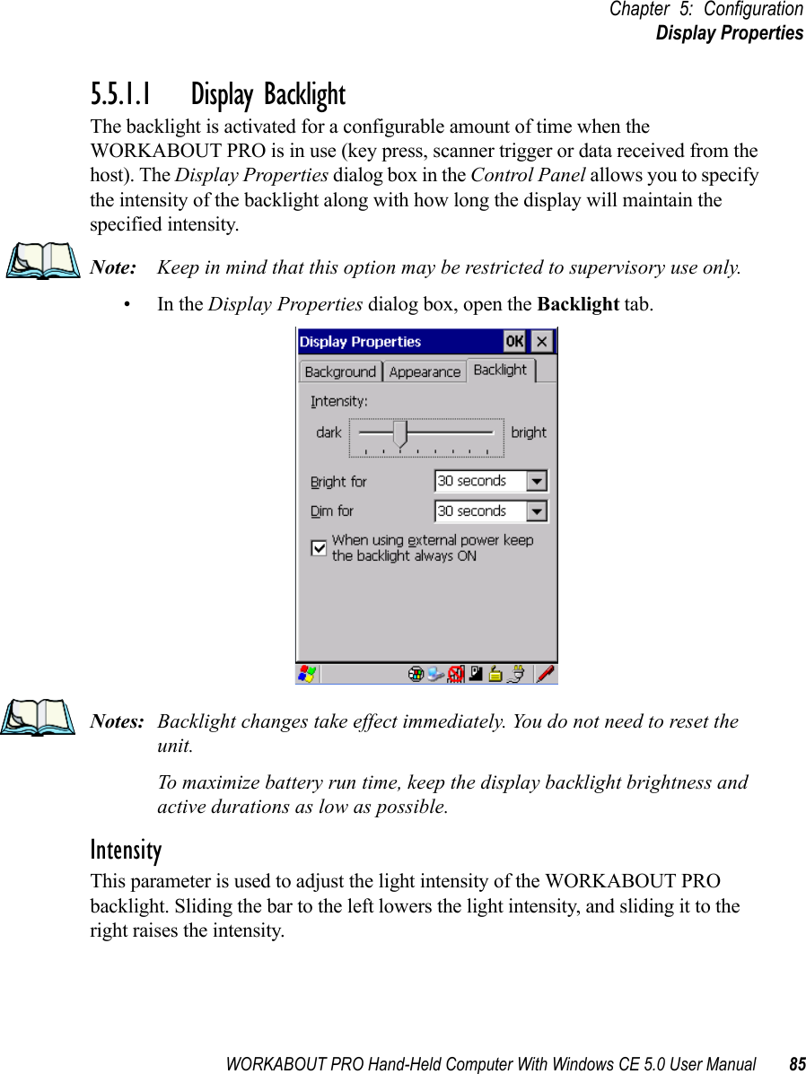
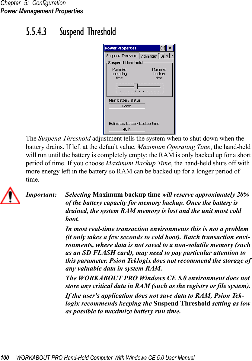
![WORKABOUT PRO Hand-Held Computer With Windows CE 5.0 User Manual 99Chapter 5: ConfigurationPower Management Properties5.5.4.2 Power Saving Suspend•In the Power Properties dialog box, open the Suspend tab.Power SourceThis dialog box allows you to specify the suspend time for either AC Power or Battery Power.Suspend TimeoutImportant: Psion Teklogix recommends setting the Suspend value to 10 min-utes. To further reduce power consumption, carefully consider the duration of time that the display backlight is ‘on’ (see “Display Backlight” on page 85).When the WORKABOUT PRO is idle—not receiving any user input (a key touch, a scan, and so on) or system activity (serial data, an activity initiated by an application, and so on)—the hand-held uses the value assigned in the Suspend Timeout field to determine when the unit will go to sleep (appear to be off). When the time in the Suspend Timeout field elapses without any activity, the unit enters suspend state. In suspend state, the WORKABOUT PRO CPU enters a sleep state, and the radio is shut off. The state of the device (RAM contents) is preserved. Pressing [ENTER] wakes the system from suspend state. When the WORKABOUT PRO is in suspend state, the network connection will not be broken immediately. If the connection is dropped, you must re-establish the network connection.](https://usermanual.wiki/Psion/7527SBTRA2041M.User-Manual-Part-2/User-Guide-851397-Page-23.png)
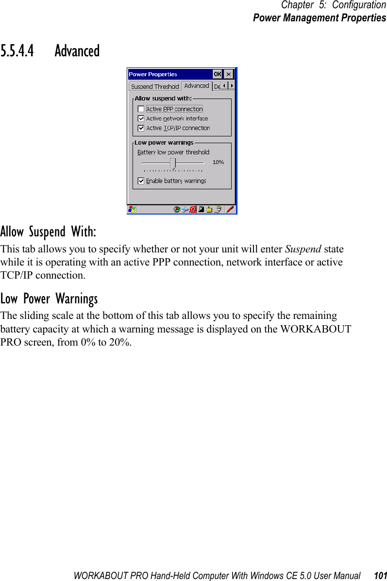
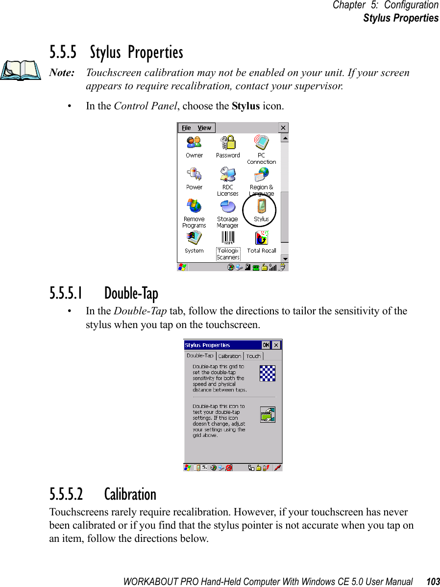
![Chapter 5: ConfigurationPower Management Properties102 WORKABOUT PRO Hand-Held Computer With Windows CE 5.0 User Manual5.5.4.5 DevicesThis tab controls power to individual CF and SDIO slots, and built-in devices. Enable or disable the checkboxes as needed, then tap on OK to save your changes.5.5.4.6 WakeupThis option allows you to define which key(s) can be pressed to wake the hand-held from a suspend state. If the Two key wakeup option is checked, the operator will need to press two keys – [FN/BLUE][ENTER] – to switch the hand-held on.](https://usermanual.wiki/Psion/7527SBTRA2041M.User-Manual-Part-2/User-Guide-851397-Page-26.png)
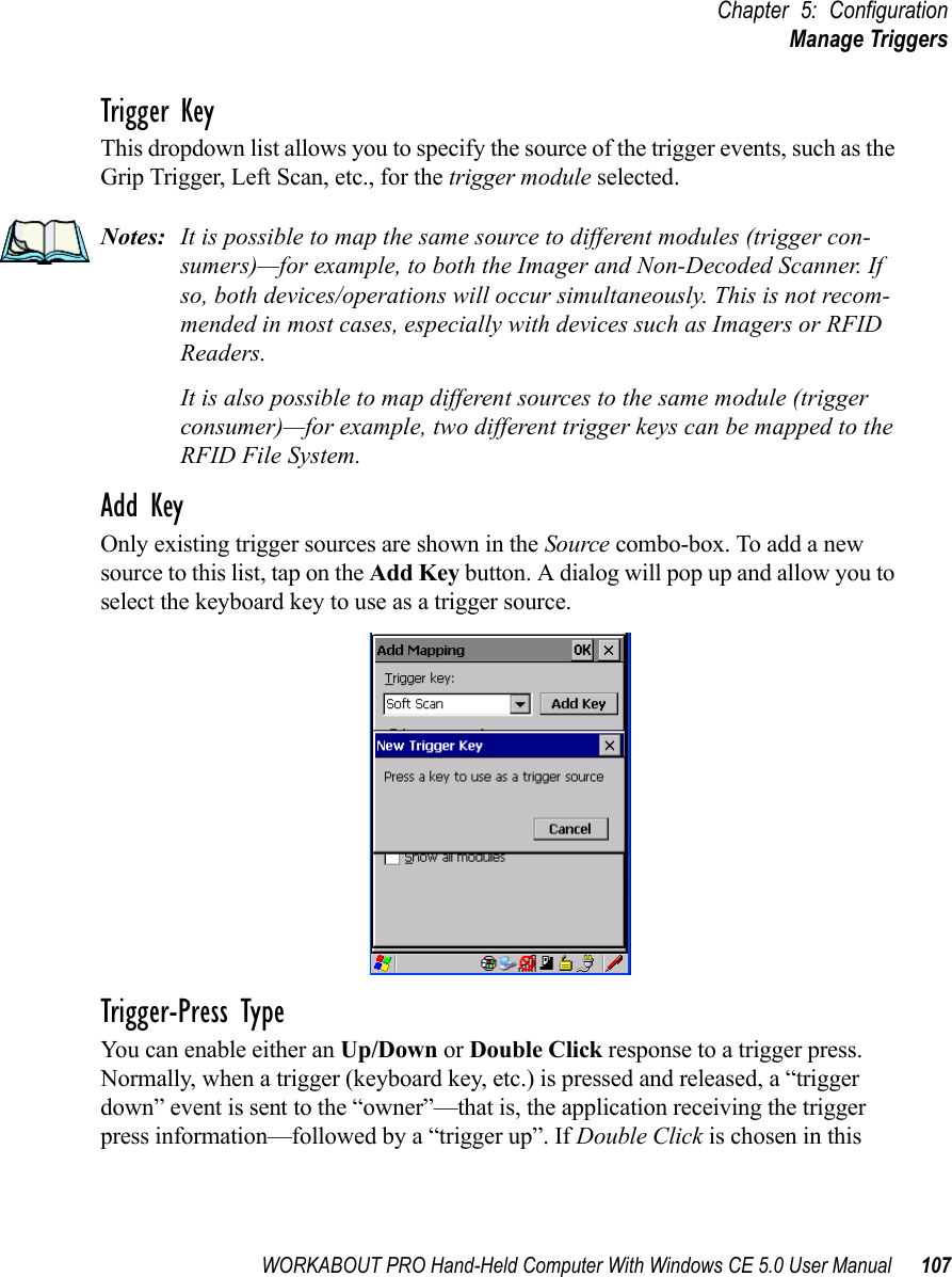
![WORKABOUT PRO Hand-Held Computer With Windows CE 5.0 User Manual 105Chapter 5: ConfigurationManage Triggers•In the Manage Triggers screen you’ll see a list of trigger mappings.5.5.6.1 Trigger MappingsA trigger mapping is an association between a particular key on the keyboard and a driver or application, the module(s)– sometimes referred to as “trigger consumer(s)”–of the trigger source. Along with keyboard keys, trigger sources can also be grip triggers, external hardware triggers or software-based. When the specified key is pressed, the trigger consumer (for example, a decoded scanner) is sent a message.Important: It is not possible to have two or more identical mappings—for example [F1] cannot be mapped to the Non-Decoded Scanner twice—even if the trigger type is different.A keyboard key that is used as a trigger source will no longer gen-erate key data or perform its normal function. For example, if the space button is used as a trigger source, it will not be able to send space characters to applications.Double-ClickWhen a key is pressed and released, then pressed again within the configured time (between 0 to 1000 milliseconds), a double-click occurs. See also “Trigger-Press Type” on page 107.](https://usermanual.wiki/Psion/7527SBTRA2041M.User-Manual-Part-2/User-Guide-851397-Page-29.png)
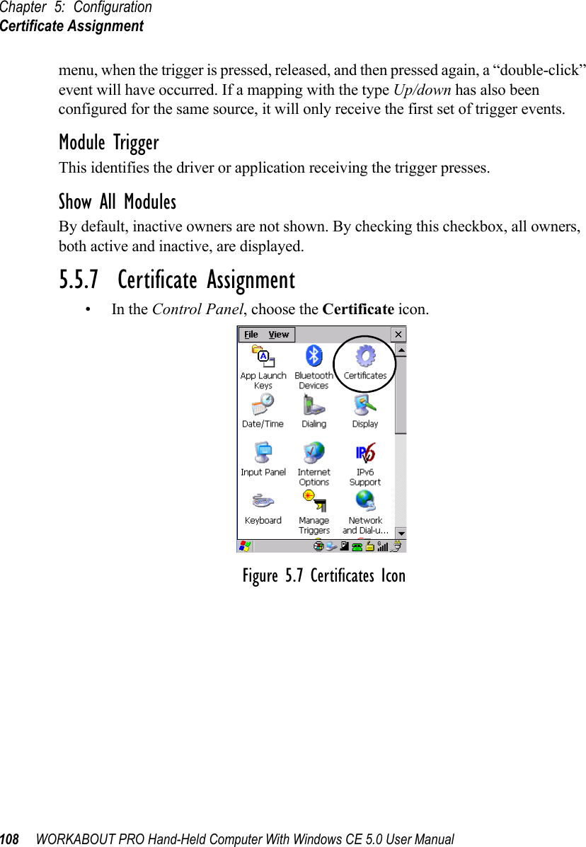
![Chapter 5: ConfigurationManage Triggers106 WORKABOUT PRO Hand-Held Computer With Windows CE 5.0 User ManualShow All ModulesBy default, the trigger mapping list only shows active mappings. Mappings for drivers or applications that are not currently active are not normally displayed. By checking this checkbox, all mappings, both active and inactive, are displayed.AddTapping this button brings up the Add mapping dialog (see page 106), so that you can add new trigger mappings.EditTapping this button brings up the Edit mapping dialog (see page 106), so that you can edit existing trigger mappings.RemoveTapping this button removes an existing mapping.OKThe OK button in the top right of the Manage Triggers screen saves all changes made. If the cancel button X is tapped instead, or the [ESC] key is pressed, all changes made will be discarded.5.5.6.2 Add And Edit Trigger MappingThese dialogs allow the user to add and edit trigger mappings.](https://usermanual.wiki/Psion/7527SBTRA2041M.User-Manual-Part-2/User-Guide-851397-Page-30.png)
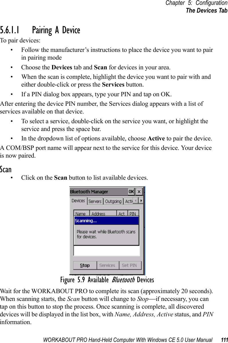
![Chapter 5: ConfigurationThe Devices Tab112 WORKABOUT PRO Hand-Held Computer With Windows CE 5.0 User ManualNote: During the scanning process, addresses are located first, followed by names. Only the names of devices that are within the Bluetooth radio cov-erage range will be retrieved.The Active column indicates whether any service is activated for that device. When a service is activated, the device is displayed in the list even when it is not detected during the scan. The PIN column indicates whether you have a PIN (password) set for the device.At this point you can either query for services or set the PIN for each device. Once you highlight a device in the list box, both the Services and Set PIN buttons become available.ServicesA discovered device may display several service profiles that it can use to communicate, and you will want to activate the type you need. Supported profiles that can be activated include: DUN (Dial-Up Networking service), Printer (serial service), Headset service and LANPPP (LANAccessUsingPPP service). ASync (ActiveSync) is another available profile.• To start the service scan, highlight a device in the Devices tab list, and then click on the Services button or double-click on the device entry.Note: If the remote device is out of reach or turned off, it can take a consider-able amount of time for the Services dialog box to appear—it may appear to be frozen.Once the device’s service profiles are displayed in the Services list box:• Highlight the service to be activated.• Press [SPACE] or right-click to display the Activation menu.The Activation menu contains four options: Activate, Authenticate, Outgoing,and Encrypt.Once the service is successfully activated, the assigned port (if applicable) will appear in the Port column of the Services list box. You can choose to use BSP or COM as the port name. BSP is the latest Microsoft Bluetooth stack standard, but older applications assume serial ports are COM. When using COM as the port name, the Bluetooth manager will try to find and use a free port between COM7 and COM9. When using BSP as the port name, BSP2 to BSP9 are available for use. The port is available as soon as it is activated.](https://usermanual.wiki/Psion/7527SBTRA2041M.User-Manual-Part-2/User-Guide-851397-Page-36.png)
![WORKABOUT PRO Hand-Held Computer With Windows CE 5.0 User Manual 113Chapter 5: ConfigurationThe Devices TabNote: The CH column shows the RFCOMM channel of the service if the service is RFCOMM-based. This information is not generally needed except for debugging purposes.To add a service to the Outgoing port, an active service must first be deactivated. Then you can choose the ‘Outgoing’ option from the Activation menu (highlight a service, right-click or press the [SPACE] bar to display the Activation menu).The Authentication and Encryption options can be changed only before activation. To change these after activation, deactivate the service first, then change the options.Once a service is activated, all the information regarding the service, including the RFCOMM channel number, is saved in the registry. (Some remote devices may change their RFCOMM channel numbers when they reboot, so your saved setting may not work when the remote device is rebooted. In that case, you must deactivate the service and reactivate it to detect the current RFCOMM channel.) Set PINPINs can be set for each device by pressing the Set PIN button in the Devices tab, or you can skip this step and try to connect to the device first. Important: The remote device must have authentication enabled, otherwise the PIN authentication will fail.• Highlight a device, click on the Set Pin button, and type the PIN.You will receive a message, either that the PIN has been successfully validated or that it has been rejected.If the PIN has been validated, an asterisk (*) appears in the PIN column in the Devices list box, indicating that this device has a PIN set. Once a PIN is entered, it is saved in the registry.To remove the PIN:• Choose Set PIN, and press [ENTER].If the WORKABOUT PRO attempts to connect to a remote device that has Authentication enabled and does not have a required PIN set, an Authentication Request dialog box appears. • Enter the PIN, and tap on OK to connect the devices.](https://usermanual.wiki/Psion/7527SBTRA2041M.User-Manual-Part-2/User-Guide-851397-Page-37.png)
![WORKABOUT PRO Hand-Held Computer With Windows CE 5.0 User Manual 115Chapter 5: ConfigurationOutgoing Tab5.6.3 Outgoing TabOutgoing Port acts as a serial port that can be used to connect to a list of Bluetooth devices (one at a time), but you have the freedom to switch on-the-fly.The Outgoing Port checkbox allows you to create the Outgoing port. When the port is created, the Outgoing tab lists the port name.The Outgoing list dialog box displays a list of services marked as ‘Outgoing’. The * column indicates the currently selected service. You can tap on Unselect to reset the current selection, or you can tap on Select to make a selection. The Remove button deletes the service from the outgoing list.The Prompt menu determines the behaviour of the pop-up Selection menu. Choosing Everytime causes the Selection menu to be displayed each time an outgoing port is created. If you choose Once, the menu is displayed only when a partner service is not selected.To display the Selection menu at any time:• Press [CTRL] [ALT] [F1], and switch the partner Bluetooth device. If a connection to a partner device already exists, the connection is dropped and another connection to the newly selected device is created instantly without disrupting the application that has opened the outgoing port.Note: To add a service to the Outgoing port, an active service must first be deactivated. Then you can choose the ‘Outgoing’ option from the Activa-tion menu (highlight a service, right-click or press the [SPACE] bar to display the Activation menu).](https://usermanual.wiki/Psion/7527SBTRA2041M.User-Manual-Part-2/User-Guide-851397-Page-39.png)
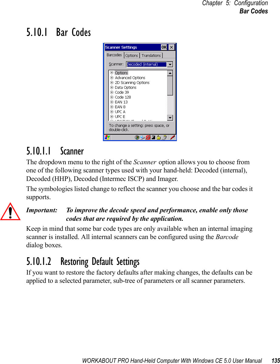
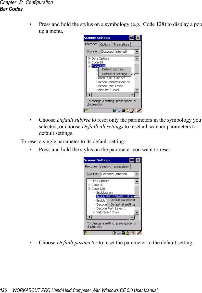
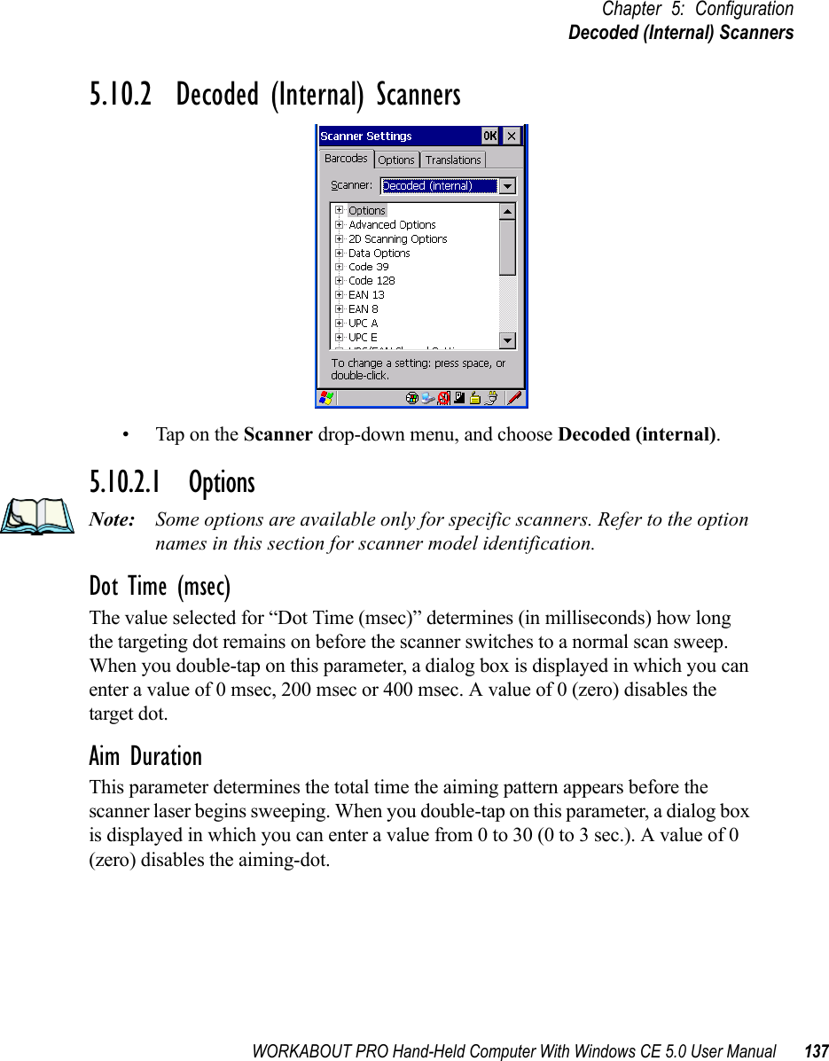
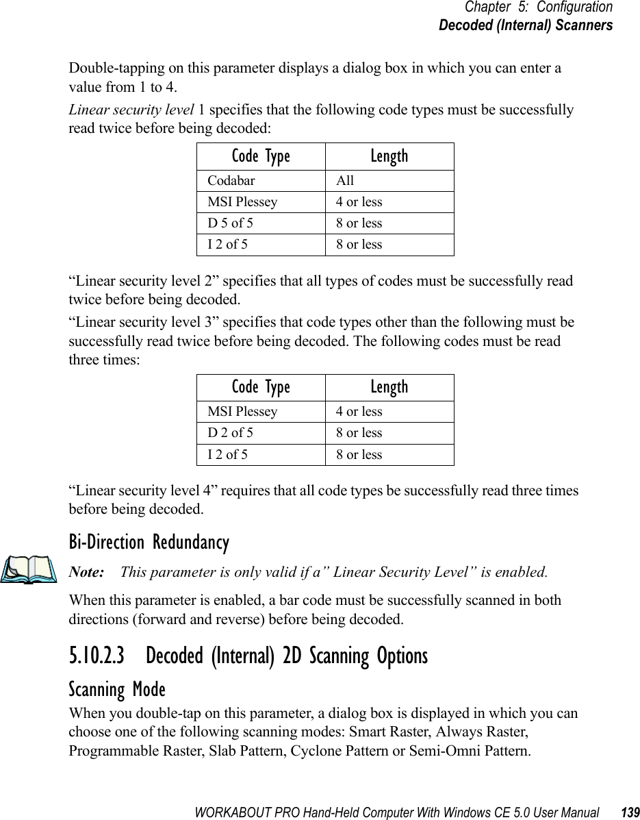
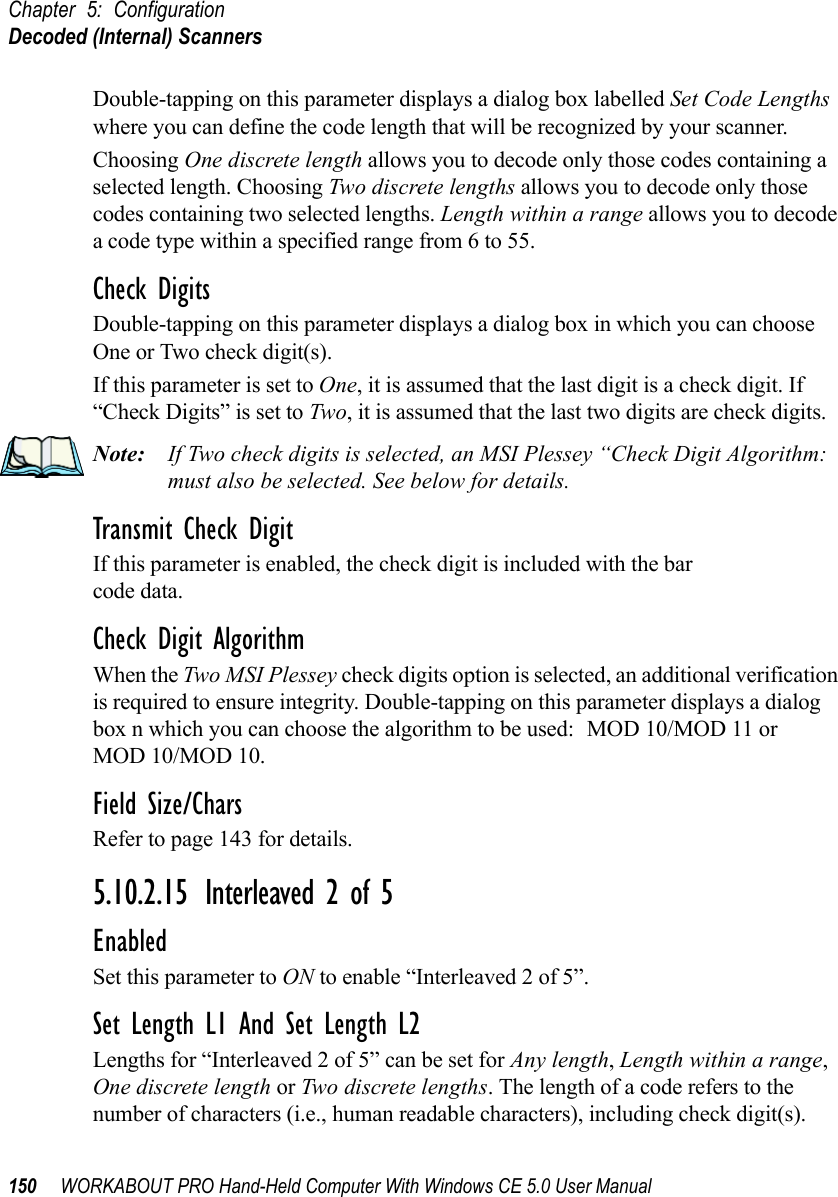
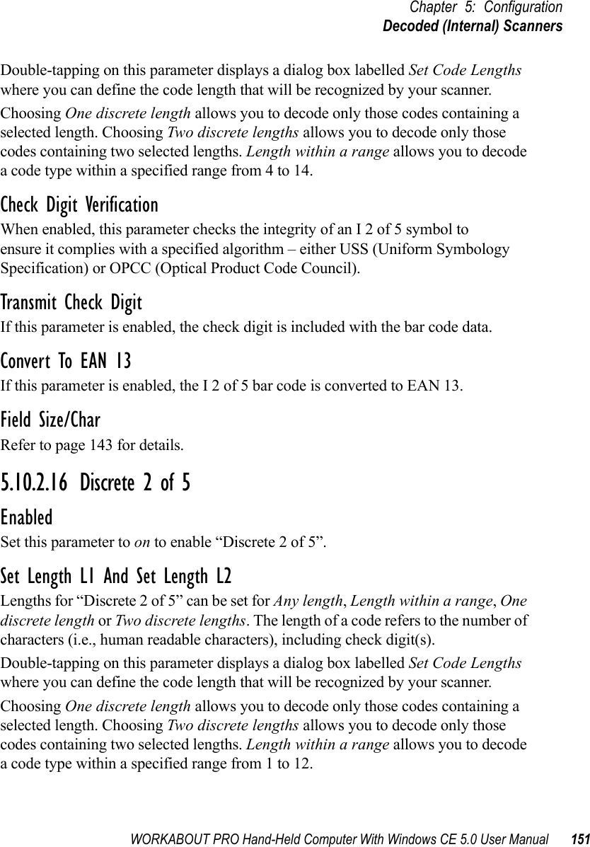
![Chapter 5: ConfigurationDecoded (Internal) Scanners140 WORKABOUT PRO Hand-Held Computer With Windows CE 5.0 User ManualRaster Height And Raster Expand RateThese parameter determine the laser pattern’s height and rate of expansion.Note: These parameters are only used when either Programmable Raster or Always Raster is assigned to the “2D Scanning Mode” parameter. “2D Raster Height” and “2D Raster Expand Rate” are intended for very specific applications and are usually not required for normal scanning purposes.Double-tapping on this parameter displays a dialog box in which you can enter a value from 1 to 15.5.10.2.4 Decoded (Internal) Data OptionsTransmit Code ID CharA code ID character identifies the scanned bar code type. In addition to any single character prefix already selected, the code ID character is inserted between the prefix and the decoded symbol.When you double-tap on this parameter, a dialog box is displayed in which you can choose a transmit code: None, AIM or Symbol.Scan Data FormatThis parameter allows you to change the scan data transmission format. Double-tapping on “Scan Data Format” displays the following options from which you can choose a data format: data (as-is), data [S1], data [S2], data [S1][S2], [P] data, [P] data [S1], [P] data [S2] and [P] data [S1][S2].Prefix [P], Suffix [S1] And Suffix [S2]A prefix and/or one or two suffixes may be appended to scan data for use in data editing.When you double-tap on these parameters, a dialog box is displayed in which you can enter a value from 0 to 255.Delete Char Set ECIsSetting this parameter to on enables the scanner to delete any escape sequences representing Character Set ECIs – Extended Channel Interpretations (also known as GLIs) from its buffer before transmission.](https://usermanual.wiki/Psion/7527SBTRA2041M.User-Manual-Part-2/User-Guide-851397-Page-58.png)

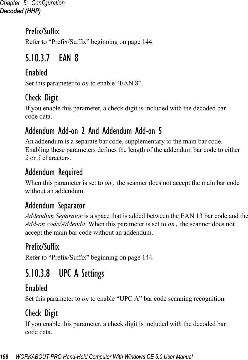
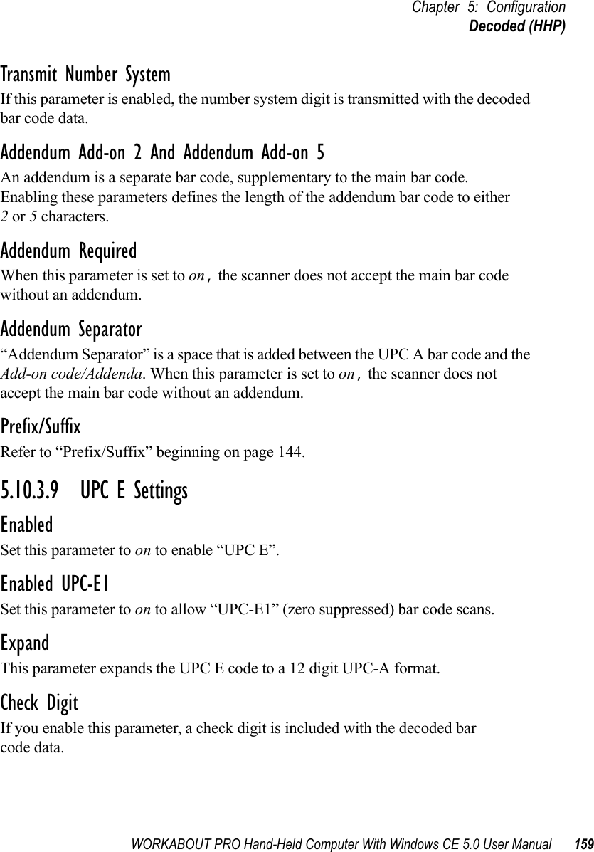
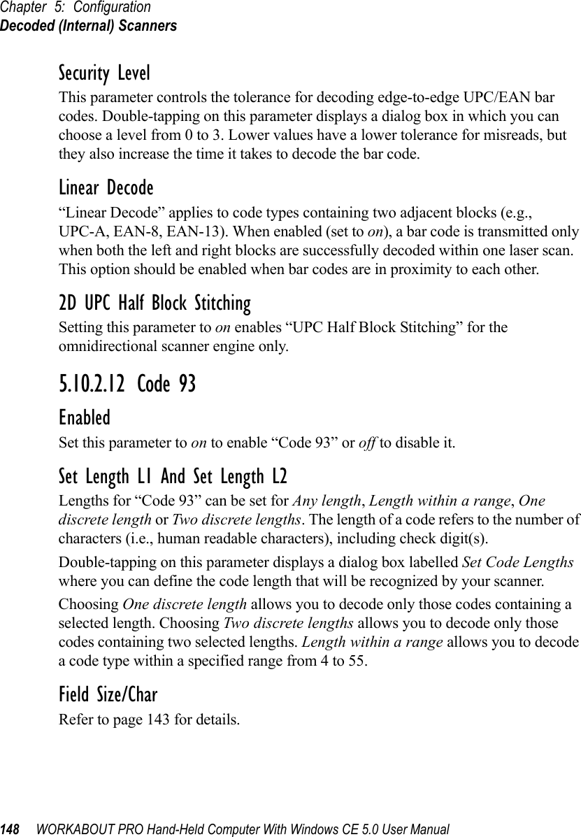
![WORKABOUT PRO Hand-Held Computer With Windows CE 5.0 User Manual 145Chapter 5: ConfigurationDecoded (Internal) ScannersSuffix CharThis character, if non-zero, is added after a successfully decoded bar code. Press the key you want to insert in the dialog box attached to this parameter. The ASCII/Unicode key value of the keypress is displayed.Strip LeadingThis parameter determines the number of characters that will be removed from the beginning of the bar code before the prefix character is added.Note: The appended character is treated as any other keyboard character. For example, if [BKSP] is pressed, the usual action for that keyis performed.Strip TrailingThe value entered in this parameter determines the number of characters that will be removed from the end of the bar code before the suffix character is added.5.10.2.8 EAN 8EnabledSet this parameter to ON to enable “EAN 8”.EAN-8 Zero ExtendWhen this parameter is enabled, five leading zeros are added to decoded EAN-8 symbols, making them compatible in format to EAN-13 symbols. Disabling this parameter returns EAN-8 symbols to their normal format.Prefix/SuffixSee “Prefix/Suffix” beginning on page 144.5.10.2.9 UPC AEnabledSet this parameter to on to enable “UPC A”.UPC-A, Check DigitIf you enable this parameter, the check digit is included with the decoded bar code data.](https://usermanual.wiki/Psion/7527SBTRA2041M.User-Manual-Part-2/User-Guide-851397-Page-63.png)
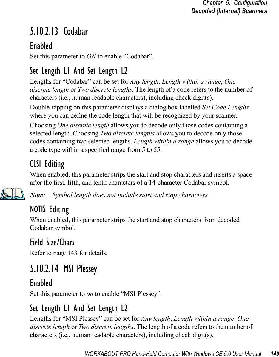
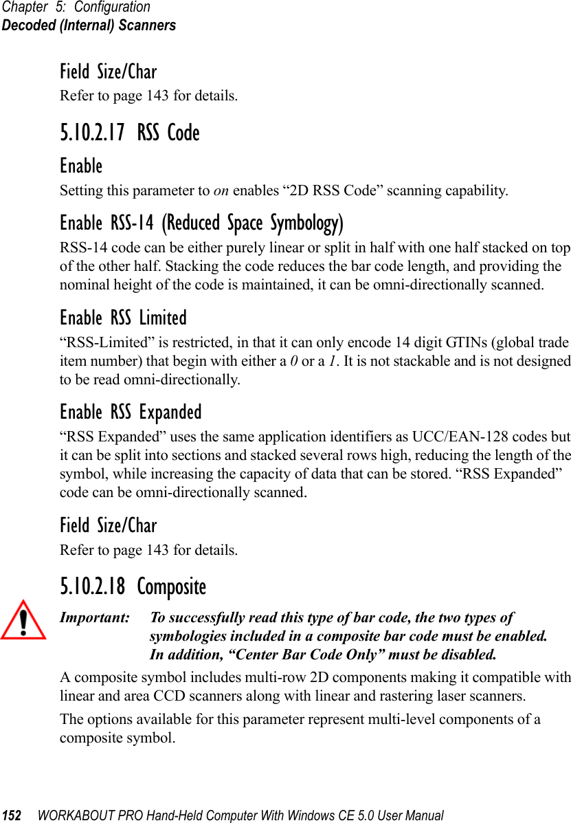
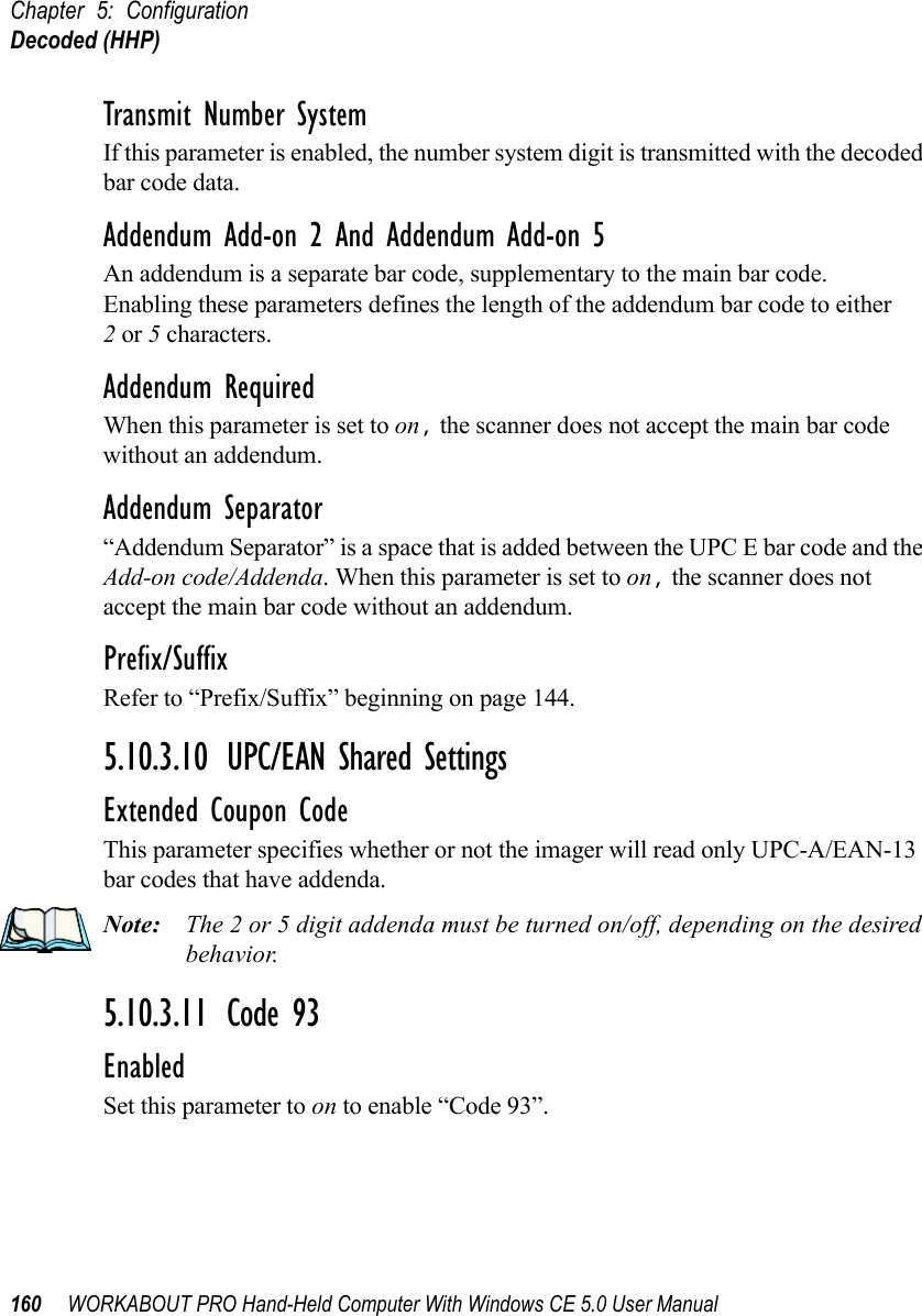
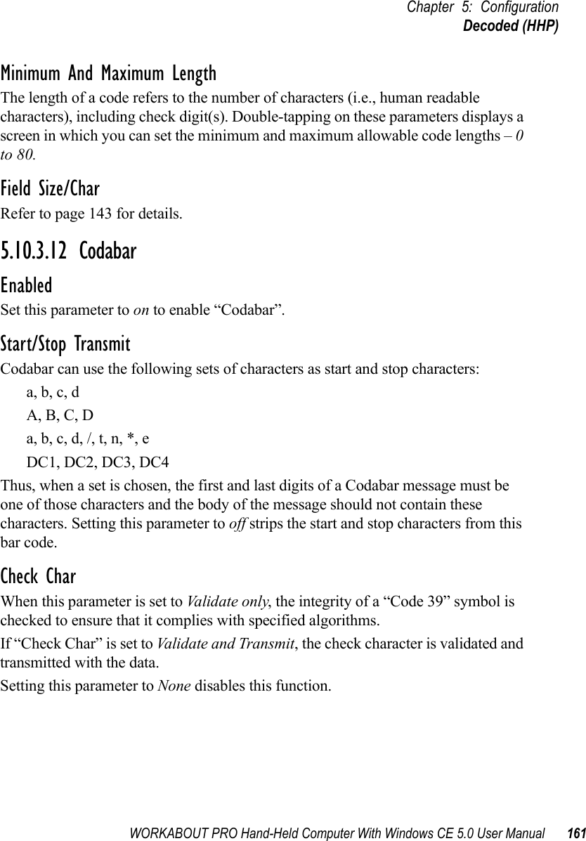
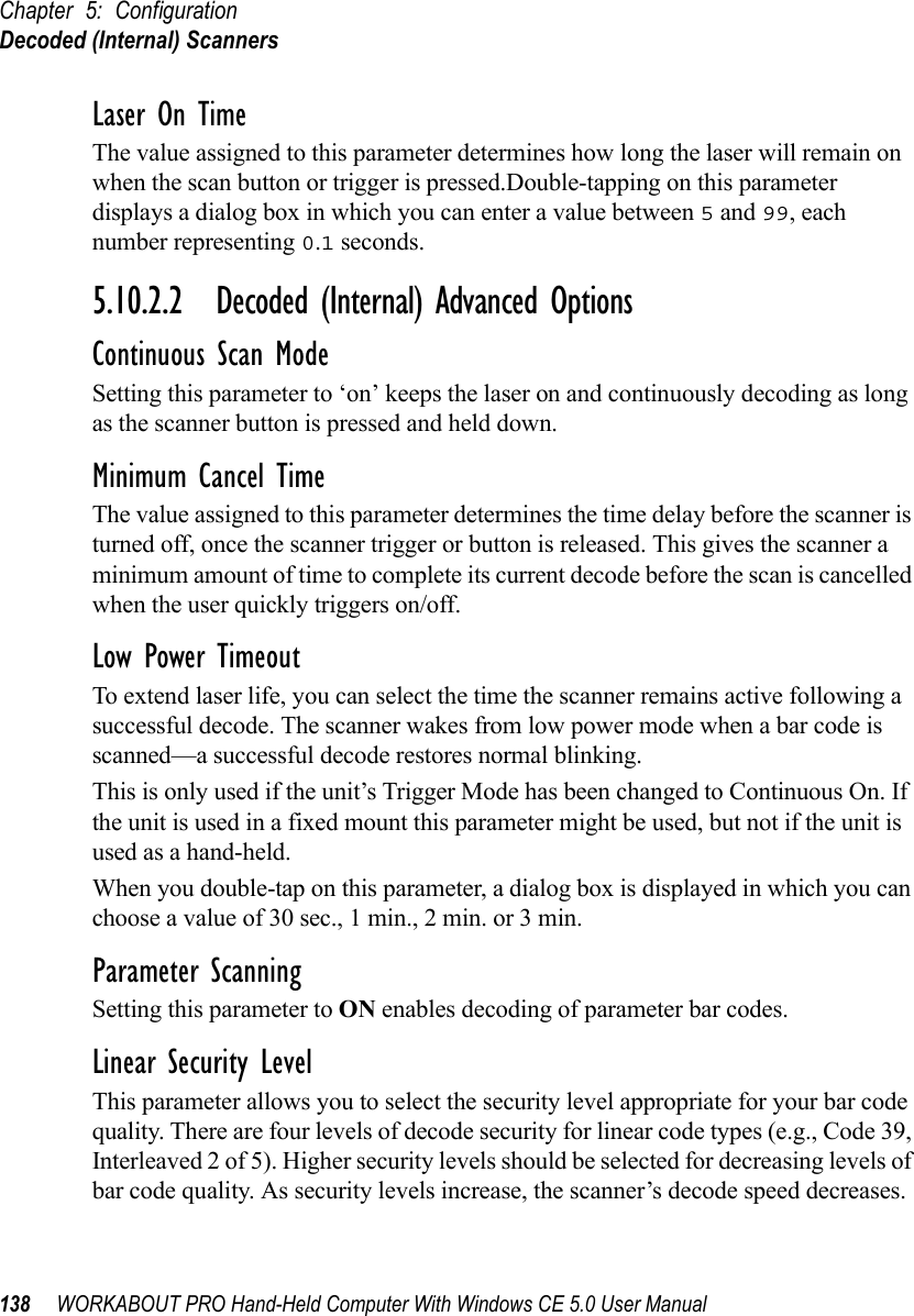
![WORKABOUT PRO Hand-Held Computer With Windows CE 5.0 User Manual 153Chapter 5: ConfigurationDecoded (Internal) ScannersEnable CC-C And Enable CC-ABTo activate these components, set these parameters to on.Enable TLC-39This composite component integrates MicroPDF417 with the linear code. Setting this parameter to on enables this parameter.5.10.2.19 PDF-417EnableSetting this parameter to on enables PDF-417 two dimensional (2D) coding.Field Size/CharRefer to page 143 for details.5.10.2.20 Micro PDF-417EnableSetting this parameter to on enables “Micro PDF-417” bar code scanning. Micro PDF-417 is a multi-row symbology that is useful for applications requiring greater area efficiency but lower data capacity than PDF-417.Code 128 EmulationWhen this parameter is enabled, the scanner transmits data from certain Micro PDF-417 symbols as if it was encoded in Code 128 symbols. If Code 128 Emulation is enabled, the following Micro PDF-417 symbols are transmitted with one of the following prefixes:]C1 if the first codeword is 903-907, 912, 914, 915]C2 if the first codeword is 908 or 909]C0 if the first codeword is 910 or 911If Code 128 Emulation is set to off, the Micro PDF-417 symbols are transmitted with one of the following prefixes:]L3 if the first codeword is 903-907, 912, 914, 915]L4 if the first codeword is 908 or 909]L5 if the first codeword is 910 or 911](https://usermanual.wiki/Psion/7527SBTRA2041M.User-Manual-Part-2/User-Guide-851397-Page-71.png)