Psion 7545MBWP GSM/GPRS/UMTS/HSPA Module User Manual Omnii Hand Held Computer
Psion Inc GSM/GPRS/UMTS/HSPA Module Omnii Hand Held Computer
UserManual.wiki
>
Psion
>
7545MBWP User Manual
>
user manual III
Contents
1.
user manual I
2.
user manual II
3.
user manual III
4.
user manual IV Regulatory Guide
5.
installation guide
user manual III
Navigation menu
Upload a User Manual
Namespaces
Wiki Guide
HTML
PDF
Info
Views
User Manual
Discussion / Help
Navigation


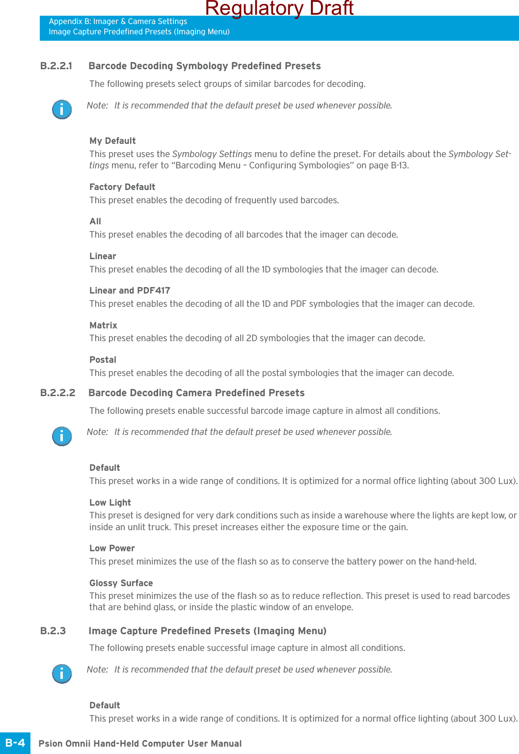
![Appendix B: Imager & Camera SettingsRequired AppletsB-3 Psion Omnii Hand-Held Computer User ManualThe Imagers applet is used to create, modify, delete, and activate imager settings. The principal uses of the application are to decode barcodes and to capture images. This imager services application is used for cameras and imagers to configure linear (1D), stacked linear, matrix (true 2D) and postal barcodes. A Dem-onstration Application is provided to demonstrate how the imager works. Refer to “Demo” on page 37 for details.B.1 Required AppletsIn order to configure imaging, the Manage Triggers applet must be present in the Control Panel, along with the Imagers applet. B.2 Presets There are two methods that can be used to configure an imager using the Imagers applet:• Use a predefined preset.• Create a custom preset based on a predefined preset.A preset is a group of exposure and image correction settings. Each preset configures the imager for a spe-cific purpose such as barcode decoding or image capture.Presets also allow easier and faster configuration of the imager after power-on or resume from suspend.The predefined presets are generic and satisfy most user requirements. A custom preset can be created for a specific user application, such as: include only specified barcodes, read only a specified number of bar-codes or for reading unusual media.Every preset belongs to a preset type. The following preset types are available:• Imaging for photo capture.• Imaging for barcode decoding.• Symbology selection.At any time, only one preset of each type can be designated as the user-selected active preset.B.2.1 Predefined PresetsPredefined presets are built into the imaging software and cannot be changed. The predefined presets allow you to use the imager to perform specified tasks without having to understand and set numerous var-iables. In almost all cases these predefined presets are sufficient.B.2.2 Barcode Predefined Presets (Barcoding Menu)These presets encompass the majority of the most popular barcodes and their subtypes. The barcode de-coding symbology predefined presets define which barcodes can be decoded. The barcode decoding camera predefined presets determine how the barcode images are captured. Note: The Imagers icon is only displayed when the appropriate imager is installed in your Omnii. If there is an imager installed but this icon is not present, additional software (ICS) may need to be installed.To enable a newly-installed imager, press and hold down the [FN] key and the [ENTER/Power] key simultaneously for a minimum of three seconds. Important: It is strongly recommended that a predefined preset is used whenever possible. Each predefined preset contains a coherent group of settings that are known to work together in the intended environment. In almost all situations, at least one of the predefined presets results in a satisfactory outcome.Regulatory Draft](https://usermanual.wiki/Psion/7545MBWP.user-manual-III/User-Guide-1680419-Page-30.png)
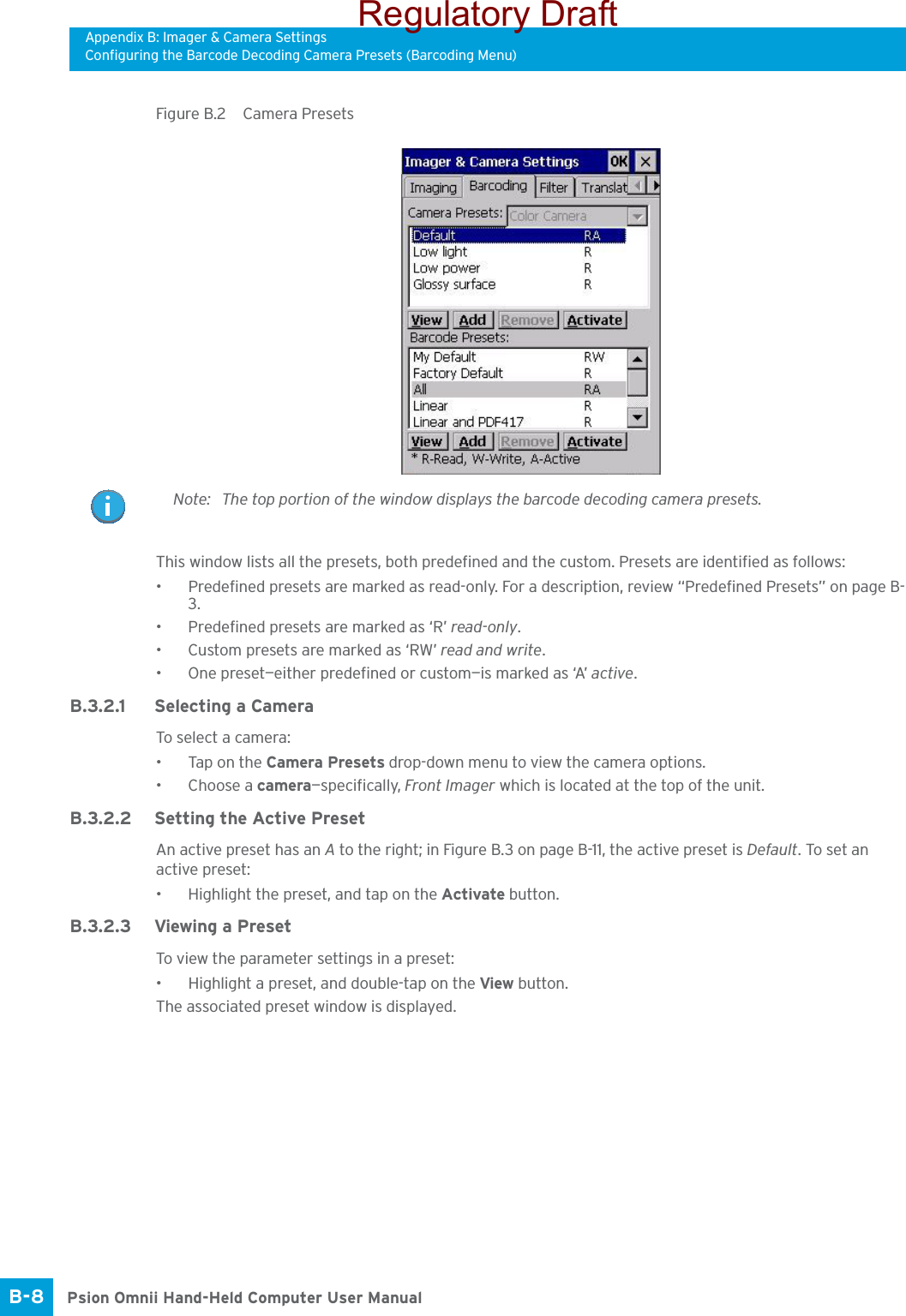
![Appendix B: Imager & Camera SettingsConfiguring the Barcode Decoding Camera Presets (Barcoding Menu)B-7 Psion Omnii Hand-Held Computer User Manual•Tap on the + symbols to expand the lists so that you can view the parameter settings.• Scroll through the parameter list until you reach the parameter that you want to change.• For a parameter that can take a range of values:- Highlight the parameter, and then press the [SPACE] key or double-click on the parameter.- An associated dialog box containing the valid range of values for the parameter and the current setting like the sample screen following is displayed.- Type a value in the field provided.• For a parameter that toggles between two values such as on or off and enabled or disabled:- Highlight the parameter and then press the [SPACE] key, or double-click on the parameter. Either method toggles between the two available values.• When you’ve completed your edits, tap on OK.The parameter list is displayed; the new value for the changed parameter is shown.•Tap on OK to exit to the preset list and save the changes.B.3.1.6 Removing a Custom Preset• Highlight the custom preset you want to delete, and tap on the Remove button.A window is displayed warning you that you are about to remove a preset.•Tap on Ye s to remove the preset or No to cancel the operation.B.3.2 Configuring the Barcode Decoding Camera Presets (Barcoding Menu)To configure the barcode decoding camera presets:•Tap on Start>Settings>Control Panel>Imagers.•Tap on the Barcoding tab.Regulatory Draft](https://usermanual.wiki/Psion/7545MBWP.user-manual-III/User-Guide-1680419-Page-34.png)
![Appendix B: Imager & Camera SettingsConfiguring the Barcode Decoding Symbologies (Barcoding Menu)Psion Omnii Hand-Held Computer User ManualB-10 • Tap on the + symbols to expand the lists and view the parameter settings.• Scroll through the parameter list until you reach the parameter that you want to change.• For a parameter that can take a range of values:- Highlight the parameter, and then press the [SPACE] key or double-click the parameter.- An associated dialog box containing the valid range of values for the parameter and the current setting like the sample screen following is displayed.- Type a value in the field provided.• For a parameter that toggles between two values such as on or off and enabled or disabled:- Highlight the parameter and then press the [SPACE] key, or double-click on the parameter. Either method toggles between the two available values.• When you’ve completed your edits, tap on OK.The parameter list is displayed; the new value for the changed parameter is shown.•Tap on OK to exit to the preset list and save the changes.B.3.2.6 Removing a Custom Preset• Highlight the custom preset you want to delete, and tap on the Remove button.A window is displayed warning you that you are about to remove a preset.•Tap on Ye s to remove the preset or No to cancel the operation.B.3.3 Configuring the Barcode Decoding Symbologies (Barcoding Menu)To configure the barcode decoding camera presets:•Tap on Start>Settings>Control Panel>Imagers.• Tap on the Barcoding tab.Regulatory Draft](https://usermanual.wiki/Psion/7545MBWP.user-manual-III/User-Guide-1680419-Page-37.png)
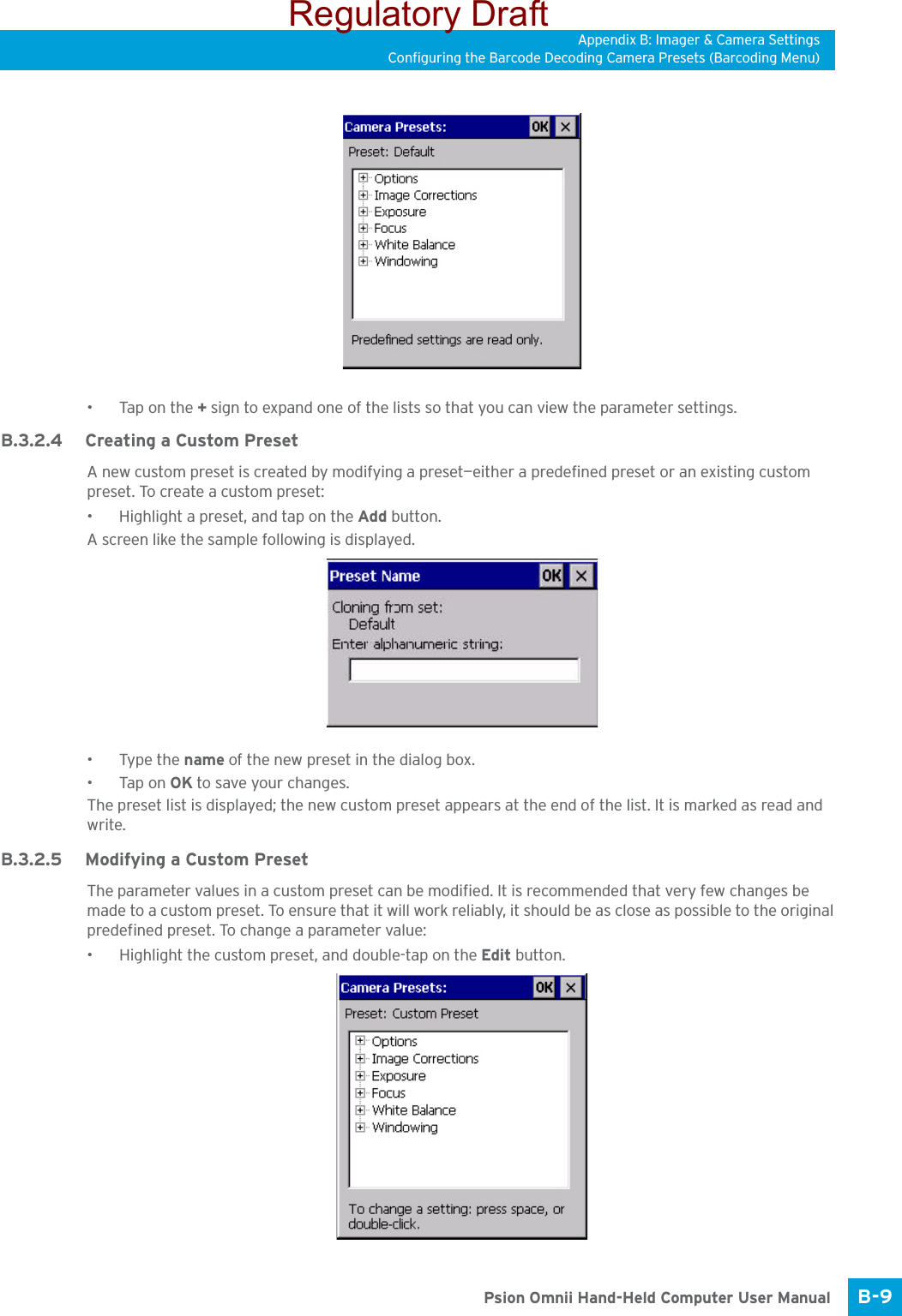
![Appendix B: Imager & Camera SettingsConfiguring the Barcode Decoding Symbologies (Barcoding Menu)Psion Omnii Hand-Held Computer User ManualB-12 • Type the name of the new preset in the dialog box.•Tap on OK to save your changes.The preset list is displayed; the new custom preset appears at the end of the list. It is marked as read and write.B.3.3.4 Modifying a Custom PresetThe parameter values in a custom preset can be modified. It is recommended that very few changes be made to a custom preset. To ensure that it will work reliably, it should be as close as possible to the original predefined preset. To change a parameter value:• Highlight the custom preset, and double-tap on the Edit button.• Tap on the + symbols to expand the lists and view the parameter settings.• Scroll through the parameter list until you reach the parameter that you want to change.• For a parameter that can take a range of values:- Highlight the parameter, and then press the [SPACE] key or double-click the parameter.- An associated dialog box containing the valid range of values for the parameter and the current setting like the sample screen following is displayed.- Type a value in the field provided.• For a parameter that toggles between two values such as on or off and enabled or disabled:- Highlight the parameter and then press the [SPACE] key, or double-click on the parameter. Either method toggles between the two available values.• When you’ve completed your edits, tap on OK.The parameter list is displayed; the new value for the changed parameter is shown.•Tap on OK to exit to the preset list and save the changes.Regulatory Draft](https://usermanual.wiki/Psion/7545MBWP.user-manual-III/User-Guide-1680419-Page-39.png)
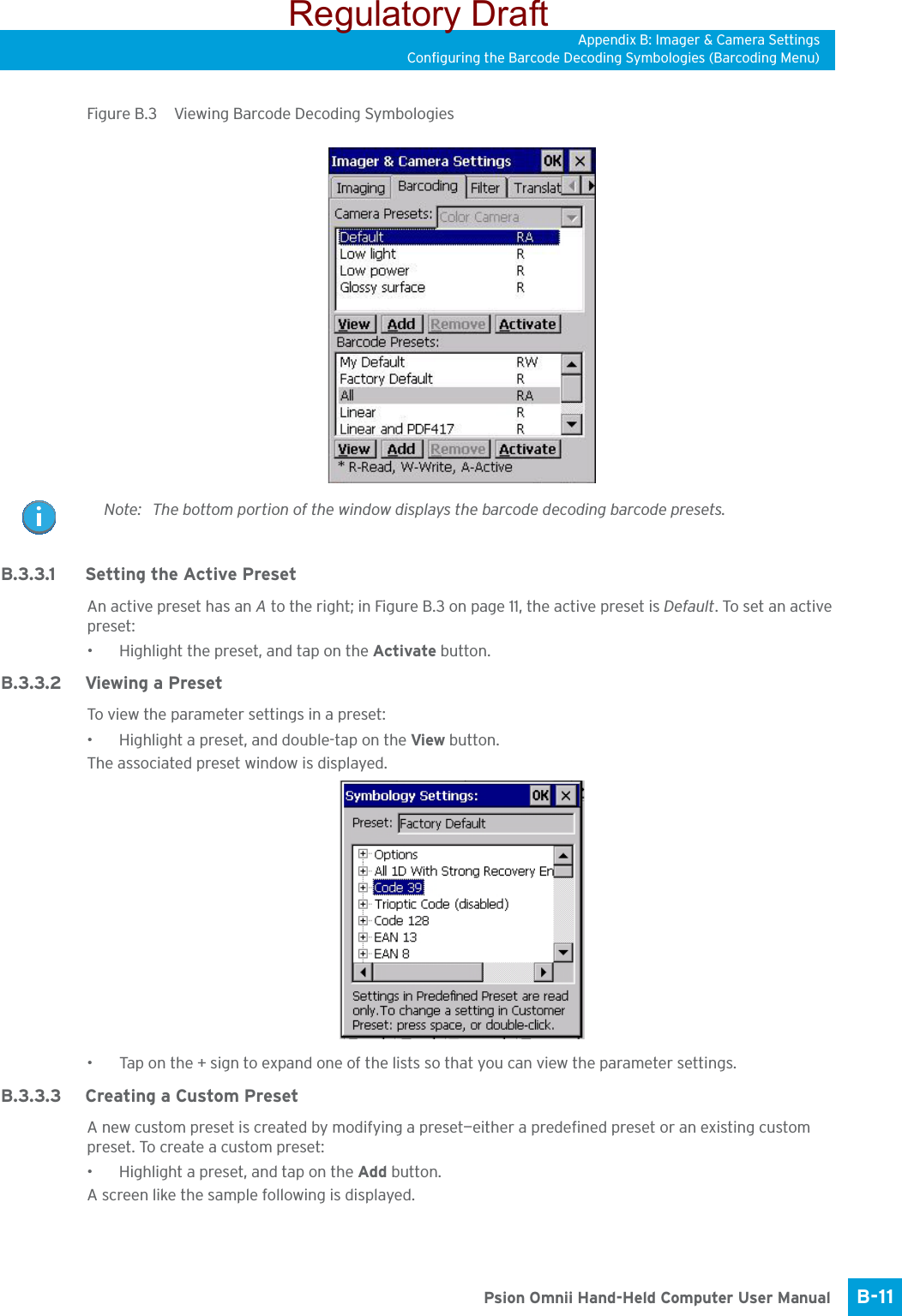
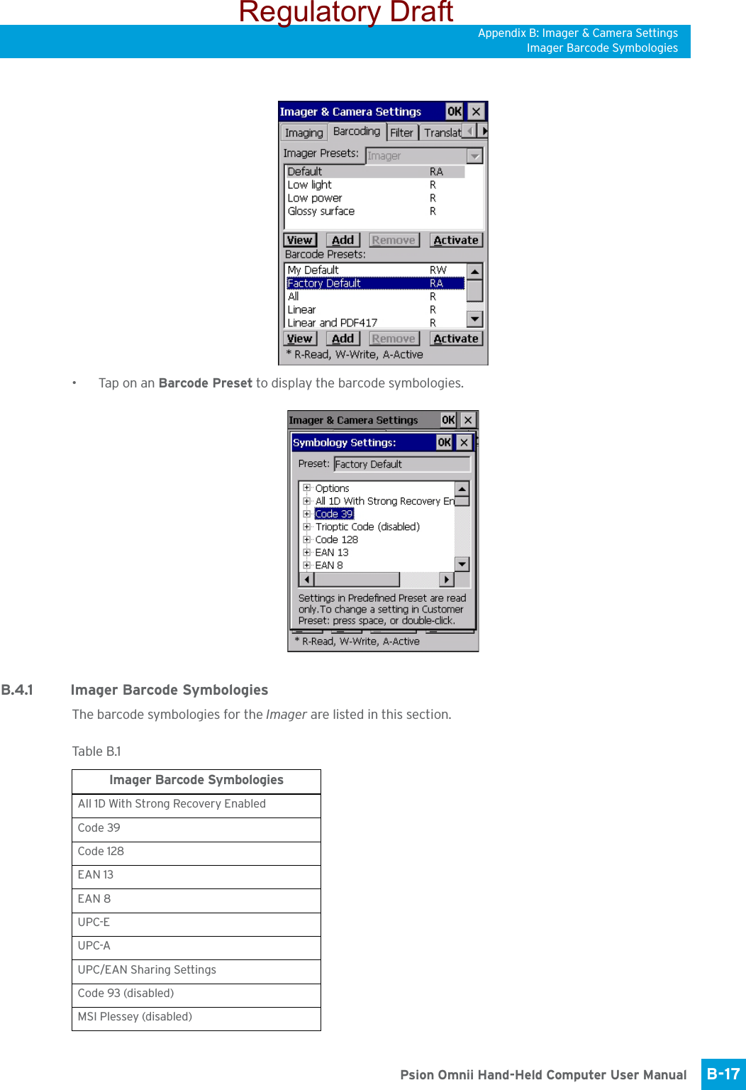
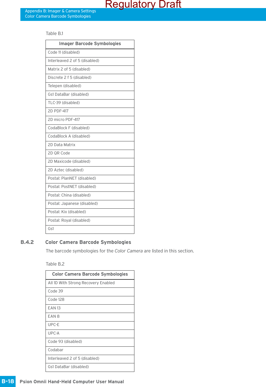
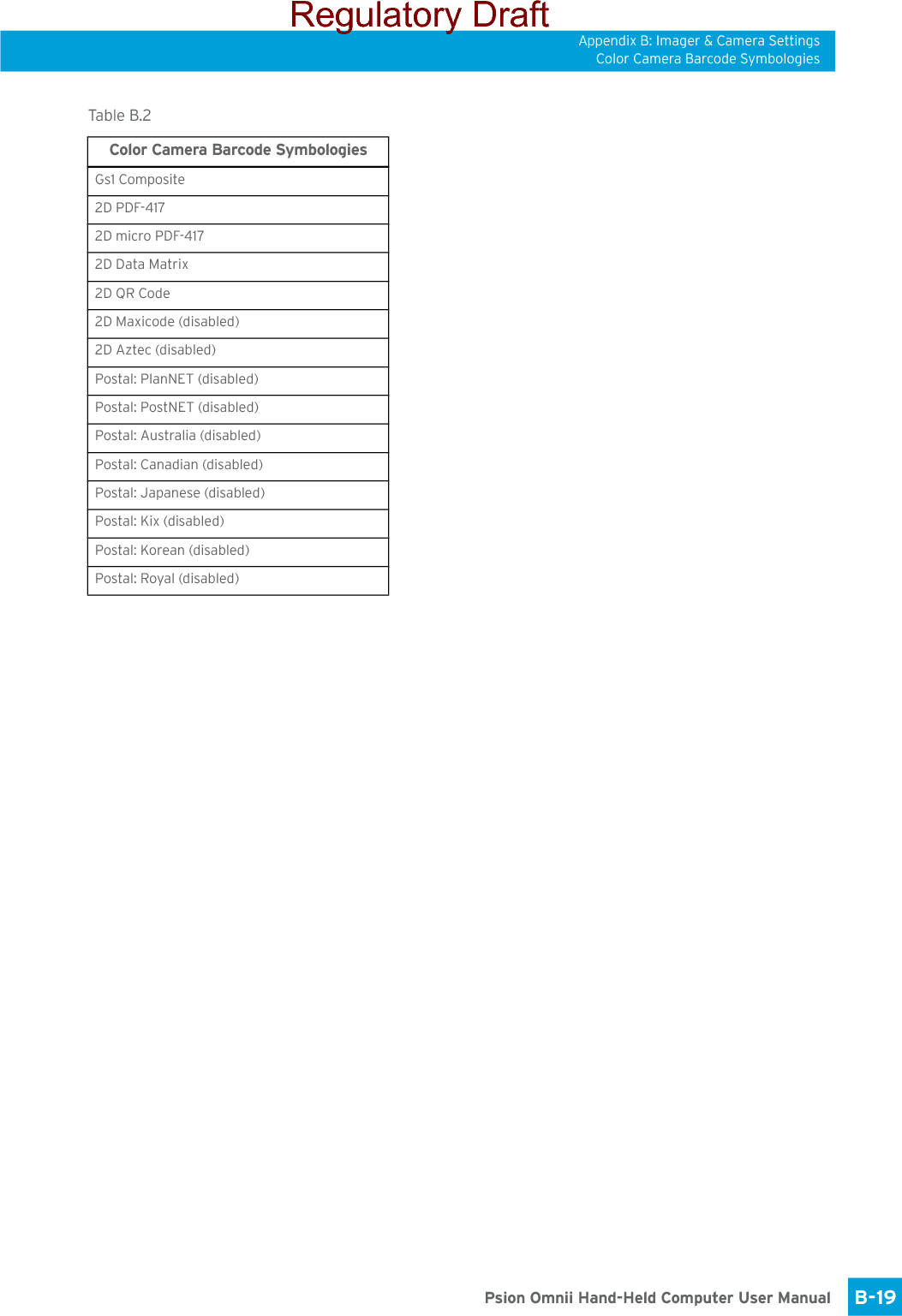
![Appendix B: Imager & Camera SettingsBarcoding Menu – Configuring SymbologiesB-13 Psion Omnii Hand-Held Computer User ManualB.3.3.5 Removing a Custom Preset• Highlight the custom preset you want to delete, and tap on the Remove button.A window is displayed warning you that you are about to remove a preset.•Tap on Ye s to remove the preset or No to cancel the operation.B.3.4 Barcoding Menu – Configuring SymbologiesTo view the Symbology Settings options:•Tap on the Barcoding tab, highlight All and then double-tap the View button.To edit a default preset, you must first activate it:•Tap on My Default, and tap on the Activate button – an A appears to the right of My Default.Once the preset is activated, you can enable or disable the barcodes the imager will read.• Highlight My Default in the Barcoding tab.• Double-tap on the Edit button.None of the other barcode decoding predefined presets are changed.B.3.4.1 Symbology SettingsB.3.5 Filter Menu – Manipulating Barcode DataTo configure rules for manipulating barcode data:•Tap on Start>Settings>Control Panel. •Tap on the Imagers icon, and then tap on the Filter tab.B.3.5.1 Modifying a Barcode SettingThe rules for manipulating data from selected barcode symbologies can be modified. To change the set-tings for a symbology:•Tap on the + symbols to expand the lists and view the parameter settings.• Scroll through the parameter list until you reach the parameter that you want to change.• For a parameter that can take a range of values:- Highlight the parameter, and then press the [SPACE] key or double-click the parameter.- An associated dialog box containing the valid range of values for the parameter and the current setting like the sample screen following is displayed.Note: For descriptions of the barcode symbologies, review “Barcode Symbologies” on page B-16.Regulatory Draft](https://usermanual.wiki/Psion/7545MBWP.user-manual-III/User-Guide-1680419-Page-40.png)
![Appendix B: Imager & Camera SettingsTranslation Menu – Configuring RulesPsion Omnii Hand-Held Computer User ManualB-14 - Type a value in the field provided.• For a parameter that takes a single character:- Highlight the parameter and then press the [SPACE] key, or double-click the parameter. The follow-ing screen is displayed:• When you’ve completed your edits, tap on OK.B.3.6 Translation Menu – Configuring RulesTranslation rules enable the automatic processing of barcode data. Up to 10 cases can be defined, each con-sisting of up to 10 sequential rules.•Tap on Start>Settings>Control Panel. • Tap on the Imagers icon, and then tap on the Translations tab.For instructions on adding, editing, and removing translation rules, refer to “Translations” on page 102.Note: Changes made to the translations configuration using the Scanner Control Panel program are synchronized with changes made here. Changes made in either place affect both translation tables.Regulatory Draft](https://usermanual.wiki/Psion/7545MBWP.user-manual-III/User-Guide-1680419-Page-41.png)


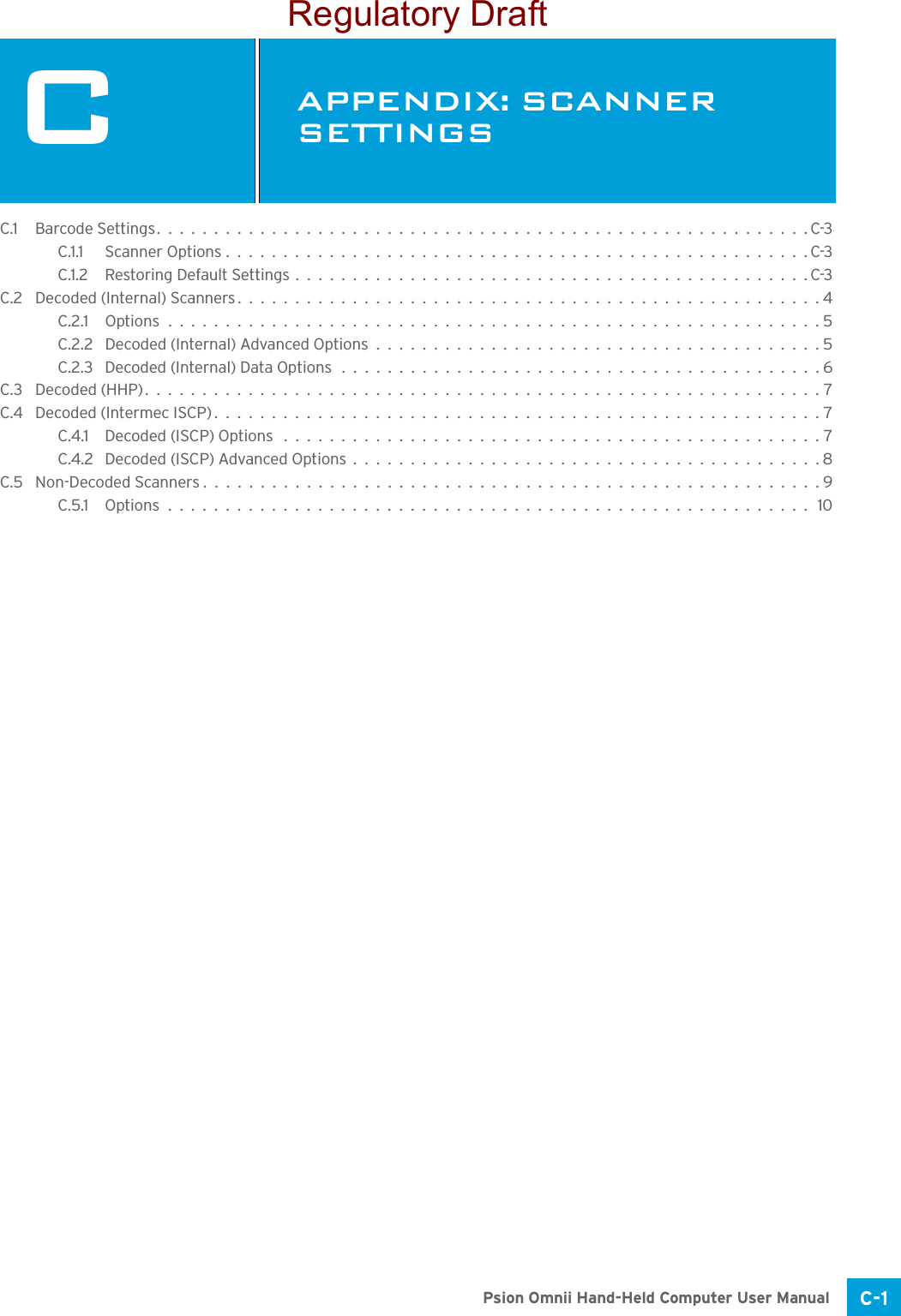

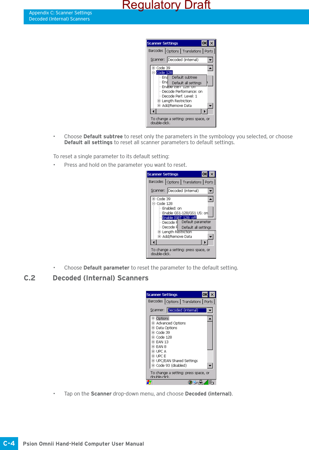
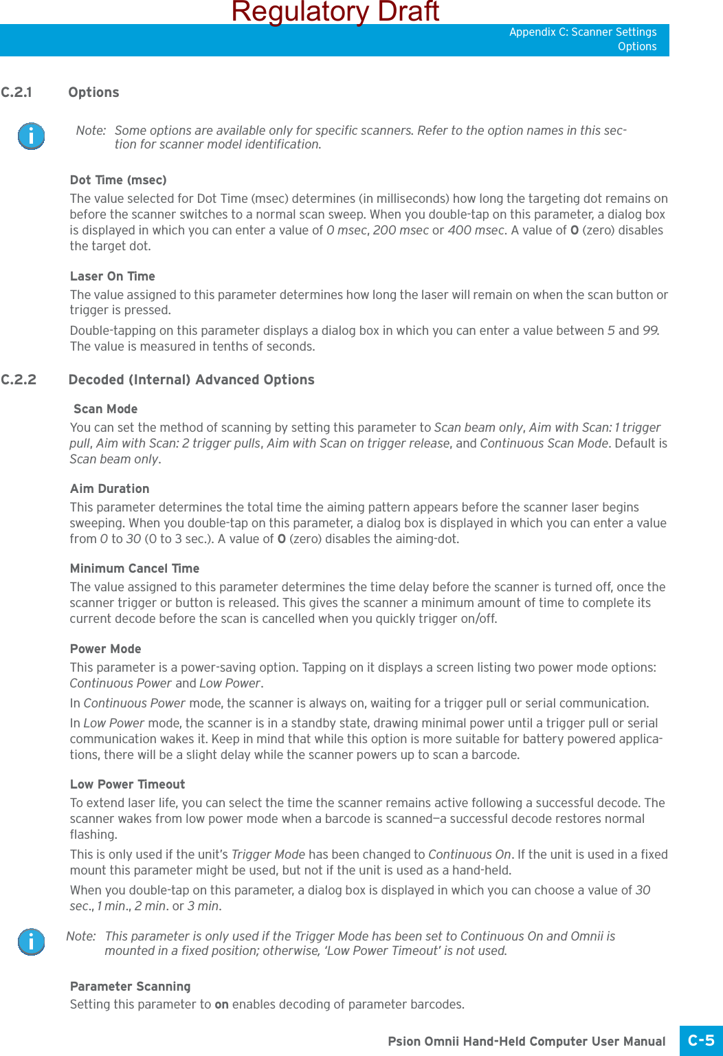
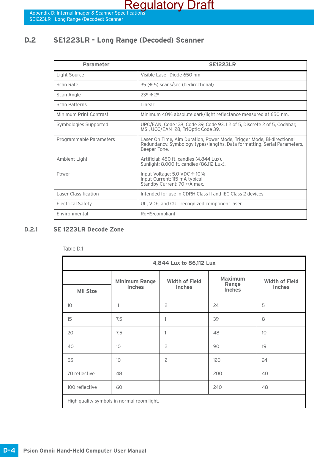
![Appendix C: Scanner SettingsBarcode SettingsC-3 Psion Omnii Hand-Held Computer User ManualC.1 Barcode SettingsThe Scanners icon in the Control Panel provides dialog boxes in which you can tailor barcode scanner con-figurations and choose the barcodes your scanner will recognize.The parameters are preset with the default settings of the decoded scanner installed in the unit. For a listing of available scanners and their specifications, please refer to Chapter E: “Omnii Specifications”. C.1.1 Scanner OptionsThe drop-down menu to the right of the Scanner option allows you to choose configurations for one of the following scanner types, depending on what is installed in/on your hand-held: Decoded (internal), Decoded (HHP), Decoded (Intermec ISCP, and Non-decoded Scanners.The symbologies listed change to reflect the scanner you choose and the barcodes it supports. Always defer to your barcode scanner’s programming manual when in doubt about the availability or settings for any parameter. Keep in mind that some barcode types are only available when an internal imaging scanner is installed. All internal scanners can be configured using these dialog boxes. C.1.2 Restoring Default SettingsIf you want to restore the factory defaults after making changes, the defaults can be applied to a selected parameter, sub-tree of parameters, or all scanner parameters. • Press and hold on a symbology (e.g., Code 128) to display a pop up a menu.Important: To enable a newly-installed scanner, press and hold down the [FN] key and the [ENTER/Power] key simultaneously for a minimum of three seconds. For information on configuring the Options, Translations, and Ports settings, see “Scanners” on page 98.Note: Your Omnii comes preconfigured from the factory for internal scanner types. The type of scanner installed can be determined from the System icon in the Control Panel, under the System Properties tab. Important: To improve the decode speed and performance, enable (set to ‘on’) only those codes that are required by the application.Regulatory Draft](https://usermanual.wiki/Psion/7545MBWP.user-manual-III/User-Guide-1680419-Page-50.png)
![Appendix C: Scanner SettingsDecoded (Internal) Data OptionsPsion Omnii Hand-Held Computer User ManualC-6 Linear Security LevelThis parameter allows you to select the security level appropriate for your barcode quality. There are four levels of decode security for linear code types (e.g., Code 39, Interleaved 2 of 5). Higher security levels should be selected for decreasing levels of barcode quality. As security levels increase, the scanner’s decode speed decreases.Double-tapping on this parameter displays a dialog box in which you can enter a value from 1 to 4. Linear security level 1 specifies that the following code types must be successfully read twice before being decoded:Linear security level 2 specifies that all types of codes must be successfully read twice before being de-coded.Linear security level 3 specifies that code types other than the following must be successfully read twice before being decoded. The following codes must be read three times:Linear security level 4 requires that all code types be successfully read three times before being decoded.Bi-Direction RedundancyWhen this parameter is enabled, a barcode must be successfully scanned in both directions (forward and re-verse) before being decoded.C.2.3 Decoded (Internal) Data OptionsTransmit Code ID CharA code ID character identifies the scanned barcode type. In addition to any single character prefix already selected, the code ID character is inserted between the prefix and the decoded symbol.When you double-tap on this parameter, a dialog box is displayed in which you can choose a transmit code: None, AIM or Symbol.Scan Data FormatThis parameter allows you to change the scan data transmission format.Double-tapping on Scan Data Format displays the following options from which you can choose a data format: data (as-is), data [S1], data [S2], data [S1][S2], [P] data, [P] data [S1], [P] data [S2] and [P] data [S1][S2].Prefix [P], Suffix [S1] and Suffix [S2]A prefix and/or one or two suffixes may be appended to scan data for use in data editing. When you double-tap on these parameters, dialog boxes are displayed in which you can enter a value from 0 to 255.Code Type LengthCodabar AllMSI Plessey 4 or lessD 5 of 5 8 or lessI 2 of 5 8 or lessCode Type LengthMSI Plessey 4 or lessD 2 of 5 8 or lessI 2 of 5 8 or lessNote: This parameter is only valid if a “Linear Security Level” is enabled.Regulatory Draft](https://usermanual.wiki/Psion/7545MBWP.user-manual-III/User-Guide-1680419-Page-53.png)
![Appendix C: Scanner SettingsDecoded (HHP)C-7 Psion Omnii Hand-Held Computer User ManualDelete Char Set ECIsSetting this parameter to on enables the scanner to delete any escape sequences representing Character Set ECIs (Extended Channel Interpretations [also known as GLIs]) from its buffer before transmission. When this parameter is enabled, the scanner transmits data from PDF417 and MicroPDF417 barcodes con-taining Character Set ECIs, even when the ECI Protocol is disabled.ECI Decoder Setting this parameter to on enables the scanner to interpret any Extended Channel Interpretations (ECIs) supported by the scanner. This parameter has no effect on symbols that were not encoded using ECIs. If this parameter is set to off and a symbol that was encoded using an ECI escape is scanned, the scanner transmits the ECI escape followed by the uninterpreted data.The barcode symbologies for the scanner are listed in Table C.1.C.3 Decoded (HHP)To configure imagers, please see Appendix B: “Imager & Camera Settings”.C.4 Decoded (Intermec ISCP)•Tap on the Scanner drop-down menu, and choose Decoded (Intermec ISCP).C.4.1 Decoded (ISCP) OptionsLaser On TimeThe value assigned to this parameter determines how long the laser will remain on when the scan button or trigger is pressed.Tabl e C.1 Decoded (Internal) Barcode SymbologiesCode 39 UPC/EAN Shared SettingsTrioptic Code (disabled) Code 93 (disabled)Code 128 Codabar (disabled)EAN 13 MSI Plessey (disabled)EAN 8 Interleaved 2 of 5 (disabled)UPC-A Discrete 2 f 5 (disabled)UPC-E Gs1 DataBar (disabled)Regulatory Draft](https://usermanual.wiki/Psion/7545MBWP.user-manual-III/User-Guide-1680419-Page-54.png)
![Appendix C: Scanner SettingsNon-Decoded ScannersC-9 Psion Omnii Hand-Held Computer User ManualThe barcode symbologies for the scanner are listed in Table C.2.C.5 Non-Decoded ScannersFigure C.1 Non-Decoded Scanner Options•Tap on the Scanner drop-down menu, and choose Non-decoded.All the available barcode symbologies for this type of scanner can be selected in this tab.A ‘plus’ sign (+) to the left of the menu item indicates that a sub-menu of parameters is attached.•Tap on the + sign to display the sub-menu.• To change a parameter value, double-tap on the parameter. If you need to type a value, a dialog box is displayed in which you can type a new value. If you need to change a yes or no value, double-tapping on the parameter toggles between yes and no.If you’re using the keyboard:• Highlight the barcode you want to work with, and press the [RIGHT] arrow key to display the sub-menu.• Use the [UP] and [DOWN] arrow keys to highlight a parameter. • To change a parameter value, press [SPACE] or the [RIGHT] arrow key. If a field requires text entry, a text box is displayed in which you can enter the appropriate value.Tabl e C. 2 Decoded (Intermec ISCP) Barcode SymbologiesCode 39 TLC-39 (disabled)Code 128 2D PDF-417EAN 13 2D micro PDF-417EAN 8 Discrete 2 of 5 (disabled)UPC-A Telepen (disabled)UPC-E Gs1 DataBar (disabled)UPC/EAN Shared Settings CompositeCode 93 (disabled) TLC-39 (disabled)Codabar (disabled) PDF-417MSI Plessey (disabled) micro PDF-417 (disabled)Code 11 (disabled) CodaBlock F (disabled)Interleaved 2 of 5 (disabled) CodaBlock A (disabled)Matrix 2 of 5 (disabled)Regulatory Draft](https://usermanual.wiki/Psion/7545MBWP.user-manual-III/User-Guide-1680419-Page-56.png)

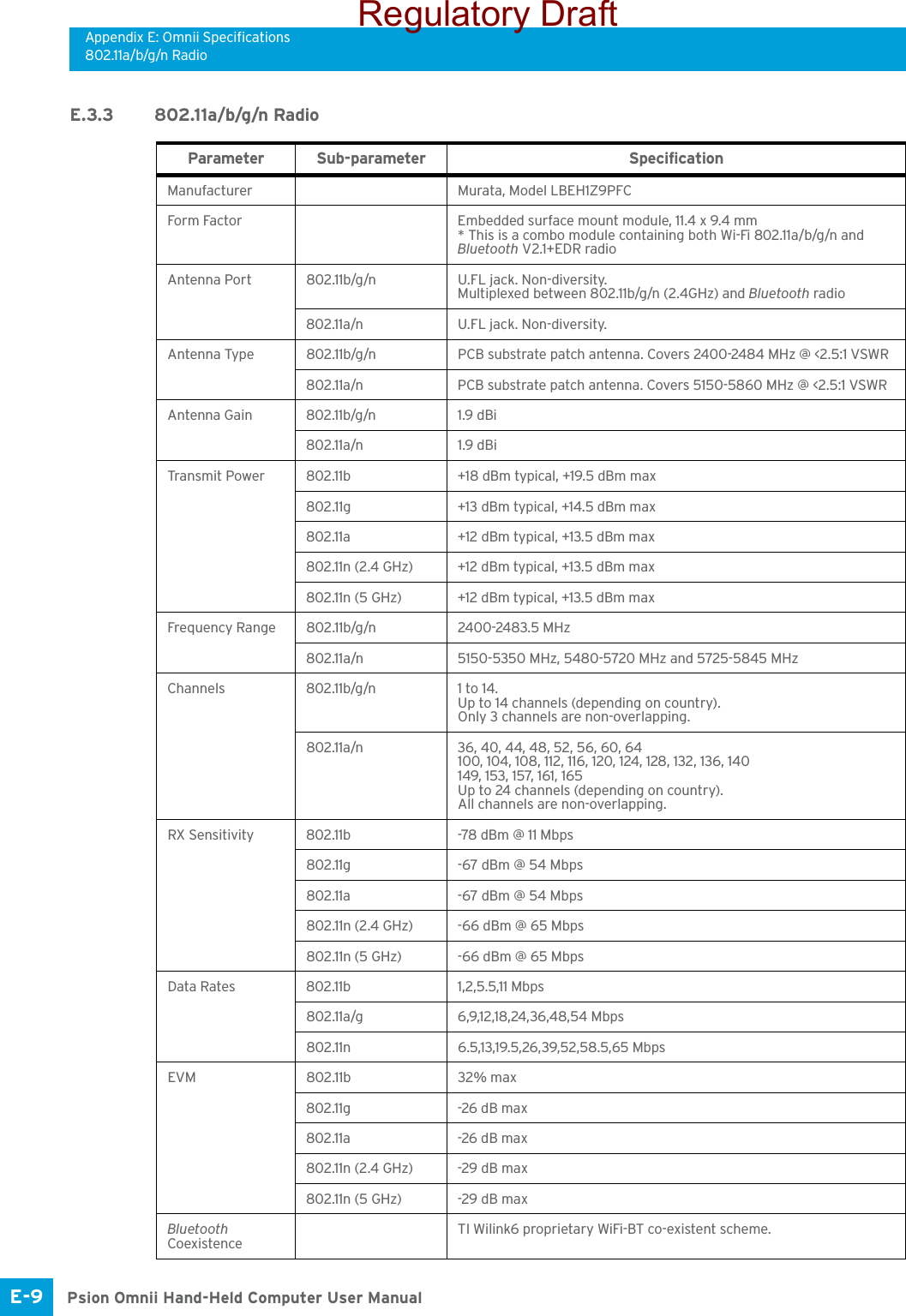
![Appendix E: Omnii SpecificationsCinterion PH8-P GSM/GPRS/EDGE RadioE-7 Psion Omnii Hand-Held Computer User ManualE.3.2 Cinterion PH8-P GSM/GPRS/EDGE RadioTabl e E.1 Feature SpecificationsGeneralFrequency bands GSM/GPRS/EDGE: Quad band, 850/900/1800/1900MHzUMTS/HSPA+: Five band, 800/850/AWS/1900/2100MHzGSM class Small MSOutput power (according to Release 99)Class 4 (+33dBm ±2dB) for EGSM850Class 4 (+33dBm ±2dB) for EGSM900Class 1 (+30dBm ±2dB) for GSM1800Class 1 (+30dBm ±2dB) for GSM1900Class E2 (+27dBm ± 3dB) for GSM 850 8-PSKClass E2 (+27dBm ± 3dB) for GSM 900 8-PSKClass E2 (+26dBm +3 /-4dB) for GSM 1800 8-PSKClass E2 (+26dBm +3 /-4dB) for GSM 1900 8-PSKClass 3 (+24dBm +1/-3dB) for UMTS 2100, WCDMA FDD Bd IClass 3 (+24dBm +1/-3dB) for UMTS 1900,WCDMA FDD Bd IIClass 3 (+24dBm +1/-3dB) for UMTS AWS, WCDMA FDD Bd IVClass 3 (+24dBm +1/-3dB) for UMTS 850, WCDMA FDD Bd VClass 3 (+24dBm +1/-3dB) for UMTS 800, WCDMA FDD Bd VIHSPA features3GPP Release 6, 7 DL 14.4Mbps, UL 5.7MbpsUE CAT. [1-6], 11, 12 supportedCompressed mode (CM) supported according to 3GPP TS25.212UMTS features3GPP Release 4 PS data rate - 384 kbps DL / 384 kbps ULCS data rate - 64 kbps DL / 64 kbps ULGSM/GPRS/EGPRS featuresData transfer GPRS:• Multislot Class 10• Full PBCCH support• Mobile Station Class B• Coding Scheme 1 - 4EGPRS:• Multislot Class 10• EDGE E2 power class for 8 PSK• Downlink coding schemes - CS 1-4, MCS 1-9• Uplink coding schemes - CS 1-4, MCS 1-9• SRB loopback and test mode B• 8-bit, 11-bit RACH• PBCCH support• 1 phase/2 phase access procedures• Link adaptation and IR• NACC, extended UL TBF• Mobile Station Class BCSD:• V.110, RLP, non-transparent• 14.4kbps• USSDSMS Point-to-point MT and MOGPS featuresProtocol NMEAModes Assisted GPS (control plane AGPS, E911)General Power saving modesGPS tracking in parallel to 2G/3G diversity operationSoftwareAT commands Hayes, 3GPP TS 27.007 and 27.005, and proprietary Cinterion Wireless Modules commandsRegulatory Draft](https://usermanual.wiki/Psion/7545MBWP.user-manual-III/User-Guide-1680419-Page-74.png)

![Appendix F: Wireless Wide Area Network (WWAN) SettingsAdvanced InformationF-5 Psion Omnii Hand-Held Computer User ManualF.1.2.2 Shutting Down the Wireless WAN User InterfaceWhile it is not usual to shut down the GSM/GPRS user interface, you can accomplish this by tapping on the File menu and choosing the Exit command at the bottom of the main Wireless WAN dialog box.F.1.3 Advanced InformationIn most cases, when a GSM/GPRS radio and SIM are installed in your computer, setup is automatic. Follow the steps outlined under the heading “Establishing a Connection” on page F-3 to make a connection. The in-formation in this section is for advanced setup purposes.F.1.3.1 Entering a PIN NumberIf a PIN is required, a PIN entry dialog box is displayed.• Type your PIN, and press [ENTER].Once the correct PIN or PUK is entered or if none was required, the modem is instructed to perform a GSM network registration followed by a GPRS attach. The main Wireless WAN dialog box reflects the progress of the initialization.• Searching for modem.• Initializing modem.•SIM is ready.• Searching for network.•Registered on network.• Searching for GPRS.• Ready to connect.If the modem loses the connection to the GSM network, the following states are repeated: Searching for network, Registered on network, Searching for packet data, and Ready to connect. F.1 . 3. 2 E r r o r S t a t e sThe following temporary error states (i.e., these states may disappear without interaction) may be dis-played:• Emergency calls only. The modem has found a network but is not allowed to register (e.g. no roaming agreement between networks). The modem keeps searching for another network.• No network found. A network is not currently available. The modem continues searching for a network.• Packet data not available. The current network does not support a packet data service.• Packet data not allowed. The modem is not allowed to use the packet data service on the current network (e.g. no GPRS roaming agreement between network; a roaming agreement for voice may still be in place). It is also possible that you do not have a subscription for GPRS at all.The remaining error states are permanent:• SIM is missing. The SIM card is missing. After the SIM has been inserted a warm boot may be required.• SIM failure. The SIM card is permanently disabled (e.g. because the wrong PUK has been entered too many times). A new SIM is needed.• Modem failure. Note: Once you’ve shut down the user interface, you can only enable the radio by opening the Con-trol Panel and tapping on the Wireless WAN icon to display the Wireless WAN dialog box.Note: If you exceed the number of allowable attempts, a PUK entry window is brought to the fore-ground. You’ll need to enter a new PIN number.Regulatory Draft](https://usermanual.wiki/Psion/7545MBWP.user-manual-III/User-Guide-1680419-Page-82.png)
![Appendix G: Wireless Zero Config SettingsAssigning An IP AddressPsion Omnii Hand-Held Computer User ManualG-6 Figure G.8 Network Key and Key Index•Key Index: This field is used to identify the WEP key. Enter a value from 1 to 4.•Enable 802.1x authentication: 802.1X is the IEEE standard that offers additional security for local area networks. It provides authentication for user devices attached to an Ethernet network, whether wired or wireless. A security protocol packet such as TLS or MD5 encapsulated in an EAP is used in conjunction with the 802.1X standard to authenticate users at the MAC layer. Available EAPs are listed in the drop-down menu next to the EAP option.To activate 802.1X, highlight 802.1x authentication, and check the checkbox.•EAP Type (Extensible Authentication Protocol): This drop-down menu lists the EAP types available on your system. The items in this drop-down menu will vary depending on your network setup. Keep in mind also that some authentication protocols require that you select a Certificate. By selecting the Properties button, you will be able to select a Certificate. “Certificates” on page 63 provides a website that outlines how to create certificates for your network.•Saving and exiting the radio setup: Once you’ve completed the configuration, press [ENTER], or tap on OK.The connection you created will be listed in the Wireless Information tab as a preferred network. The radio will search for the SSID and compare the WEP and authentication information you specified. If there is a match between the hand-held settings and the access point settings, the hand-held will com-municate on the network through the access point.G.2 Assigning An IP AddressIf your network is not using a DHCP server, you will need to assign an IP address. Refer to “IP Address” on page 126 for details about assigning an IP address. G.2.1 Name ServerRefer to “Name Server” on page 128 for details about this option.Regulatory Draft](https://usermanual.wiki/Psion/7545MBWP.user-manual-III/User-Guide-1680419-Page-97.png)
![Appendix G: Wireless Zero Config SettingsAdvanced FeaturesG-7 Psion Omnii Hand-Held Computer User ManualG.3 Advanced FeaturesTo displ ay the Advanced Wireless Settings dialog box:•Tap on the Advanced button in the Wireless Information tab. (Refer to Figure G.6.) This window lists the available preferred networks.Figure G.9 Advanced Wireless SettingsG.3.1 Rearranging Preferred NetworksOmnii attempts to connect with the networks listed in this dialog box in sequence, beginning at the top of the list. If you need to rearrange this list of networks—move networks up and down in the list:• Tap in the Networks List, and highlight the network that you want to move up or down in the list.• To move the highlighted item in the list upward or downward, tap on the Up or Down button.G.3.2 Deleting A Preferred NetworkTo delete a network from this list:•In the preferred networks list, highlight the network you want to remove.•Tap on the Delete button.G.3.3 Changing Network PropertiesTo change the properties of an existing preferred network:• Highlight the network that you want to modify.•Tap on the Properties button.• Make any necessary changes in the Wireless Properties dialog box, and press [ENTER] to save the changes.Regulatory Draft](https://usermanual.wiki/Psion/7545MBWP.user-manual-III/User-Guide-1680419-Page-98.png)