Psion 7545MBWP GSM/GPRS/UMTS/HSPA Module User Manual installation guide
Psion Inc GSM/GPRS/UMTS/HSPA Module installation guide
UserManual.wiki
>
Psion
>
7545MBWP User Manual
>
installation guide
Contents
1.
user manual I
2.
user manual II
3.
user manual III
4.
user manual IV Regulatory Guide
5.
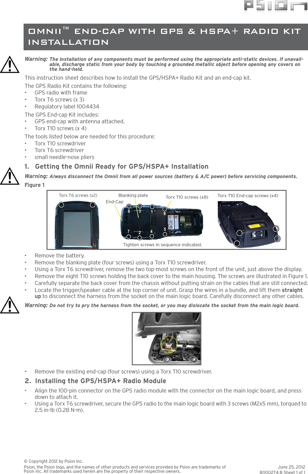
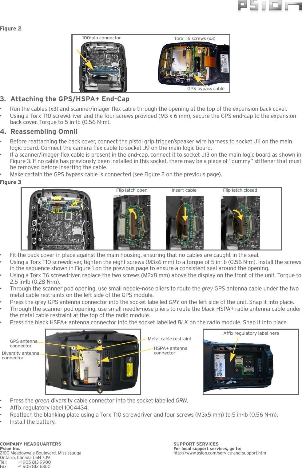
installation guide
installation guide
Navigation menu
Upload a User Manual
Namespaces
Wiki Guide
HTML
PDF
Info
Views
User Manual
Discussion / Help
Navigation