Psion RA2020 WIRELESS GATEWAY User Manual 80440
Psion Inc WIRELESS GATEWAY 80440
UserManual.wiki
>
Psion
>
RA2020 User Manual
>
USERS MANUAL 1
Contents
1.
ANTENNA CO LOCATION WARNING
2.
FCC STATEMENT INFO TO USERS
3.
LETTER OF PHOTO
4.
USERS MANUAL 1
5.
USERS MANUAL 2
6.
USERS MANUAL 3
USERS MANUAL 1
Navigation menu
Upload a User Manual
Namespaces
Wiki Guide
HTML
PDF
Info
Views
User Manual
Discussion / Help
Navigation
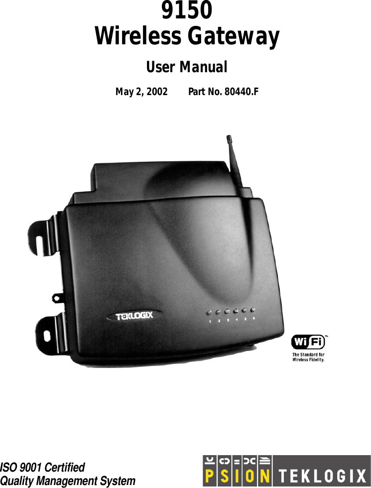
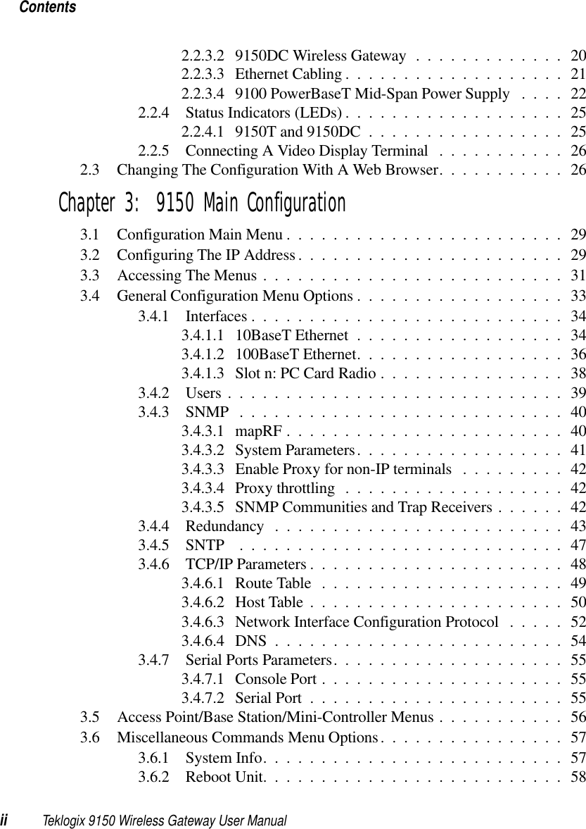
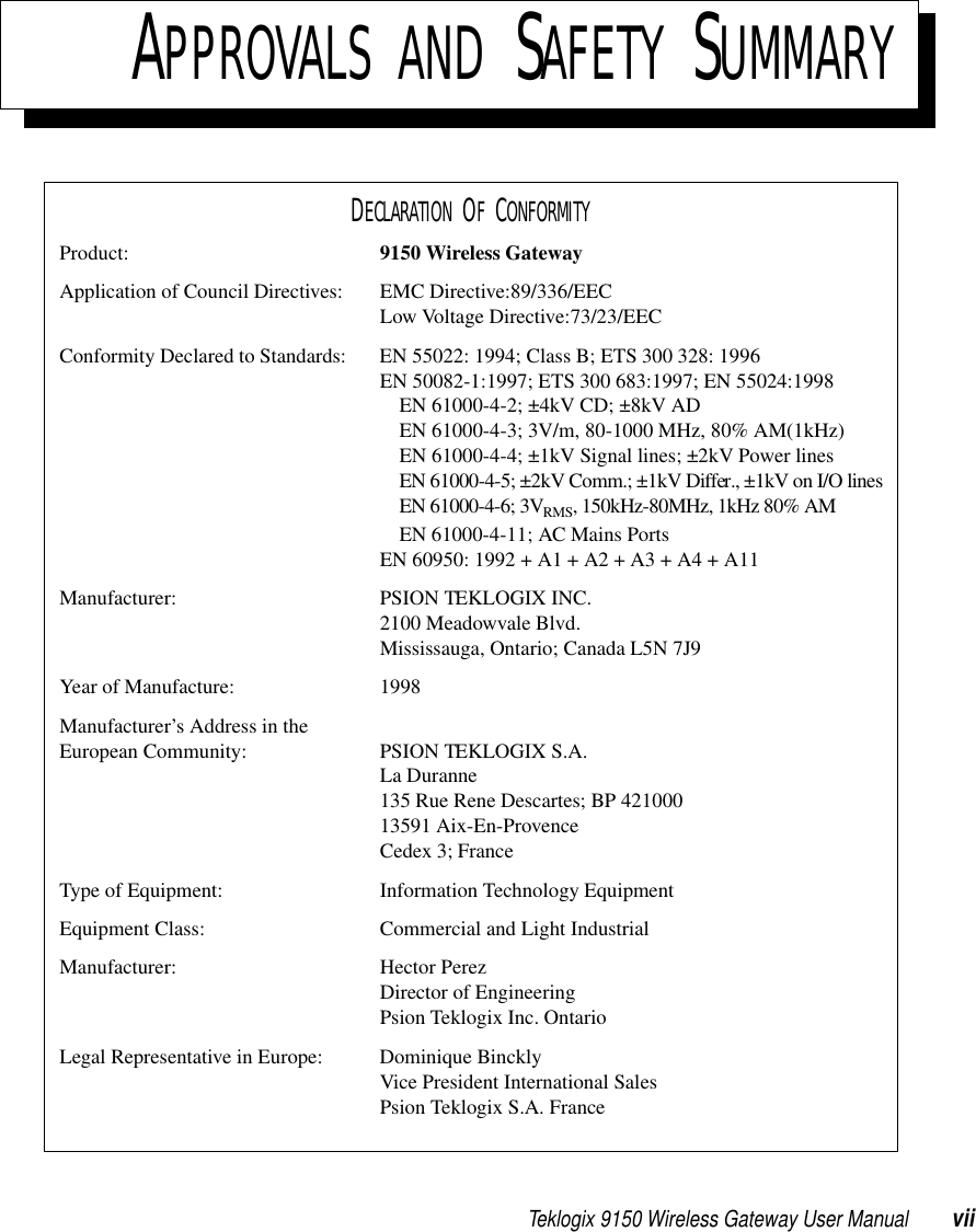
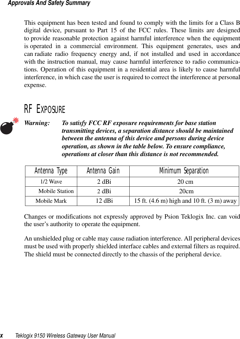
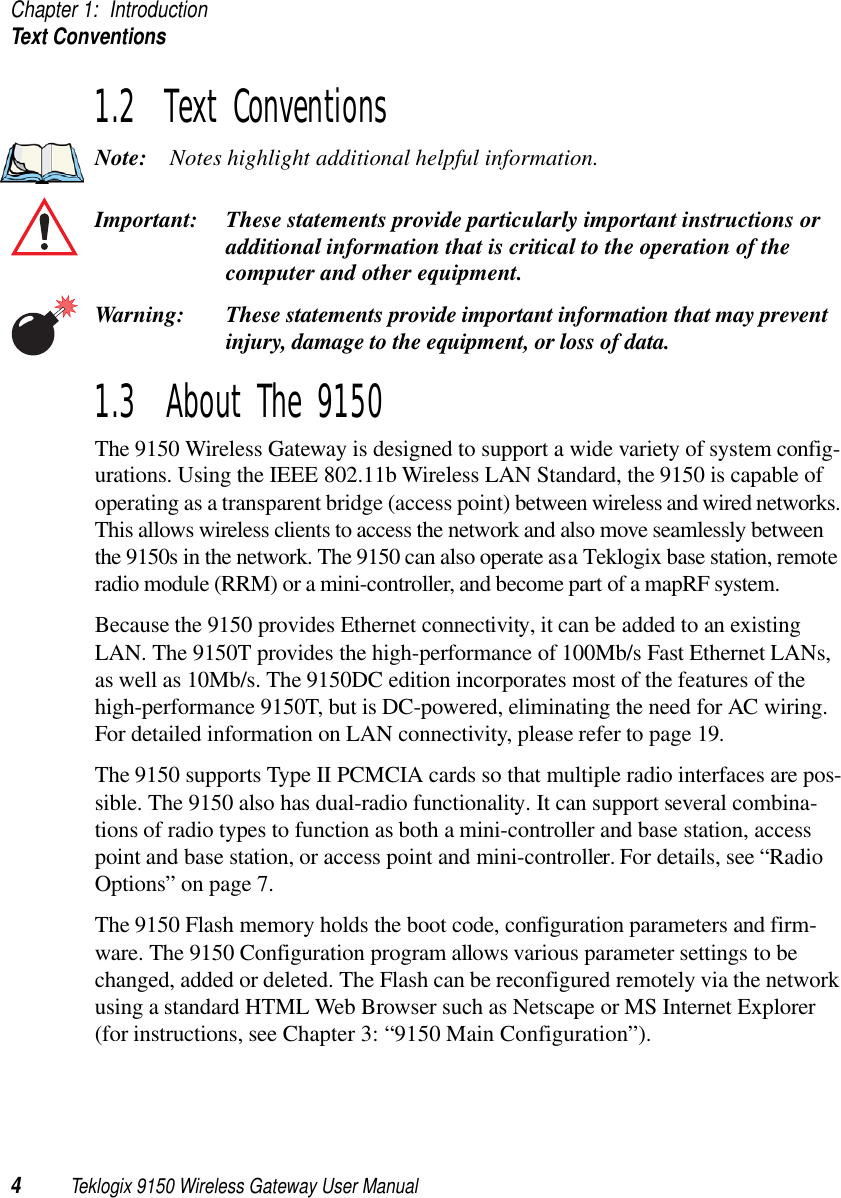
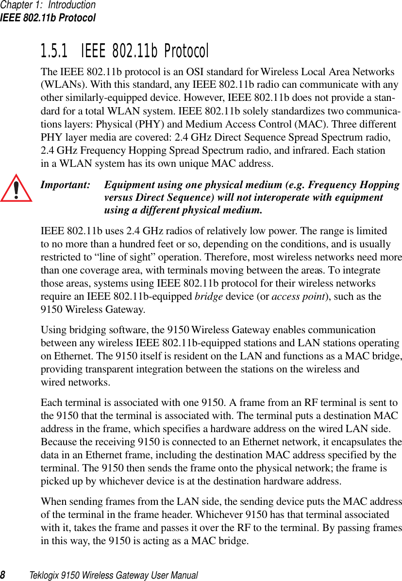
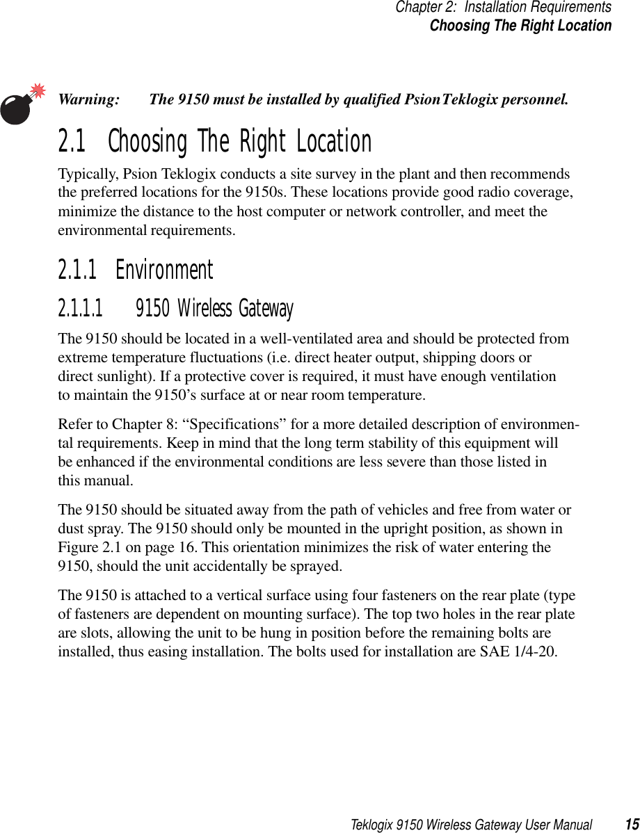
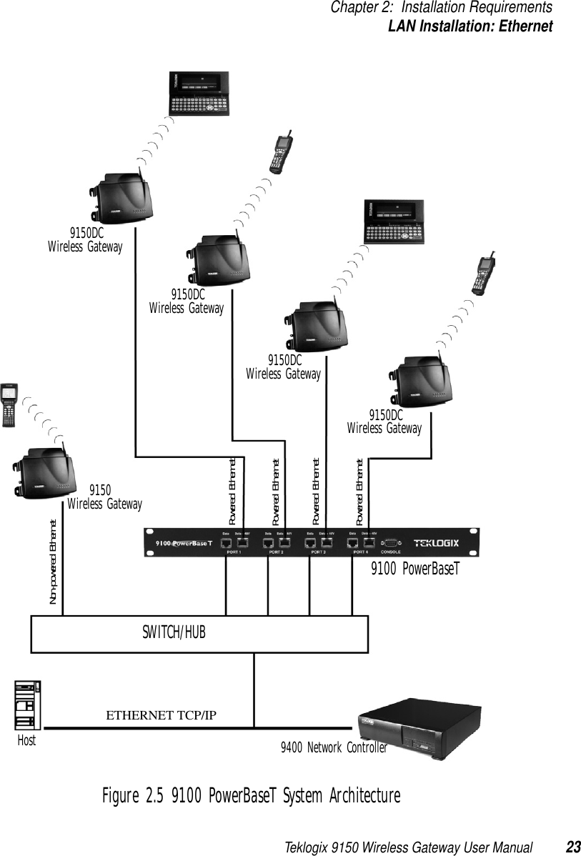
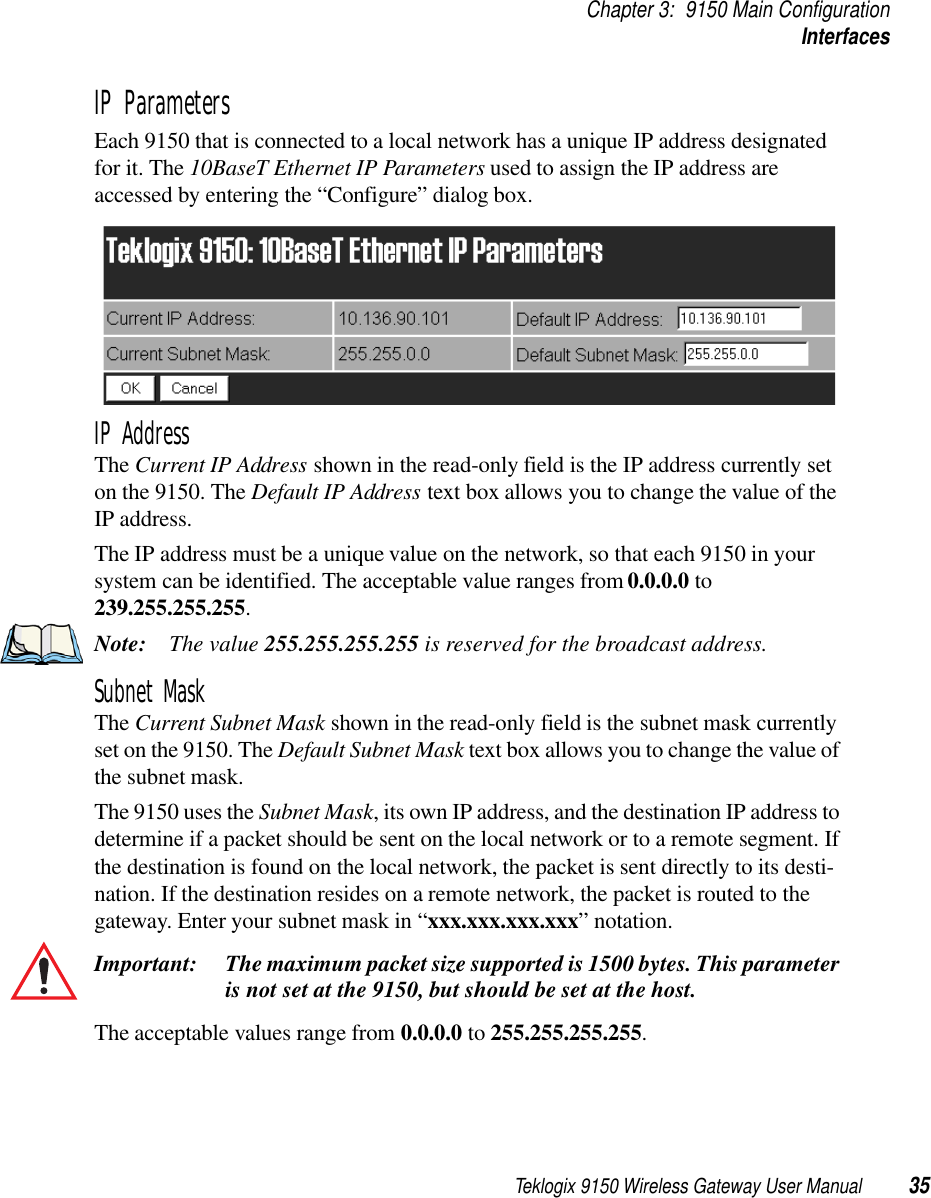
![Teklogix 9150 Wireless Gateway User Manual 19Chapter 2: Installation RequirementsConnecting To External Devices2.2 Connecting To External DevicesThis section contains general guidelines for connecting the 9150 to external devices such as network controllers, base stations, host computers, PCs and video display terminals.2.2.1 PortsFigure 2.2 below shows the locations of the port and power connectors on the base of the 9150T [100BaseT Ethernet]; for the 9150DC, see Figure 2.3 on page 21). The port pinouts are described in Appendix B: “Port Pinouts And Cable Diagrams”.Figure 2.2 9150T Ethernet LED Locations**Note: The location of the LEDs is the same on the 9150DC (see Figu re2.3 on page 21).2.2.2 LAN Installation: OverviewBecause the 9150 provides Ethernet connectivity, it can be added to an existing LAN. Generally, LAN installations are handled with the help of the network administrators, as they are familiar with their network and its configuration.Once the 9150 is installed, connected and powered on, the system administrator can access the unit to check the configuration and to assign the 9150 its unique IP address. This may be done through the Console port or through the network (see “Connecting AC Power Socket10BaseT/100BaseT Ethernet AdaptorGreenLEDsConsole PortYellowLED: 1 4 5632Operating Status](https://usermanual.wiki/Psion/RA2020.USERS-MANUAL-1/User-Guide-400310-Page-34.png)
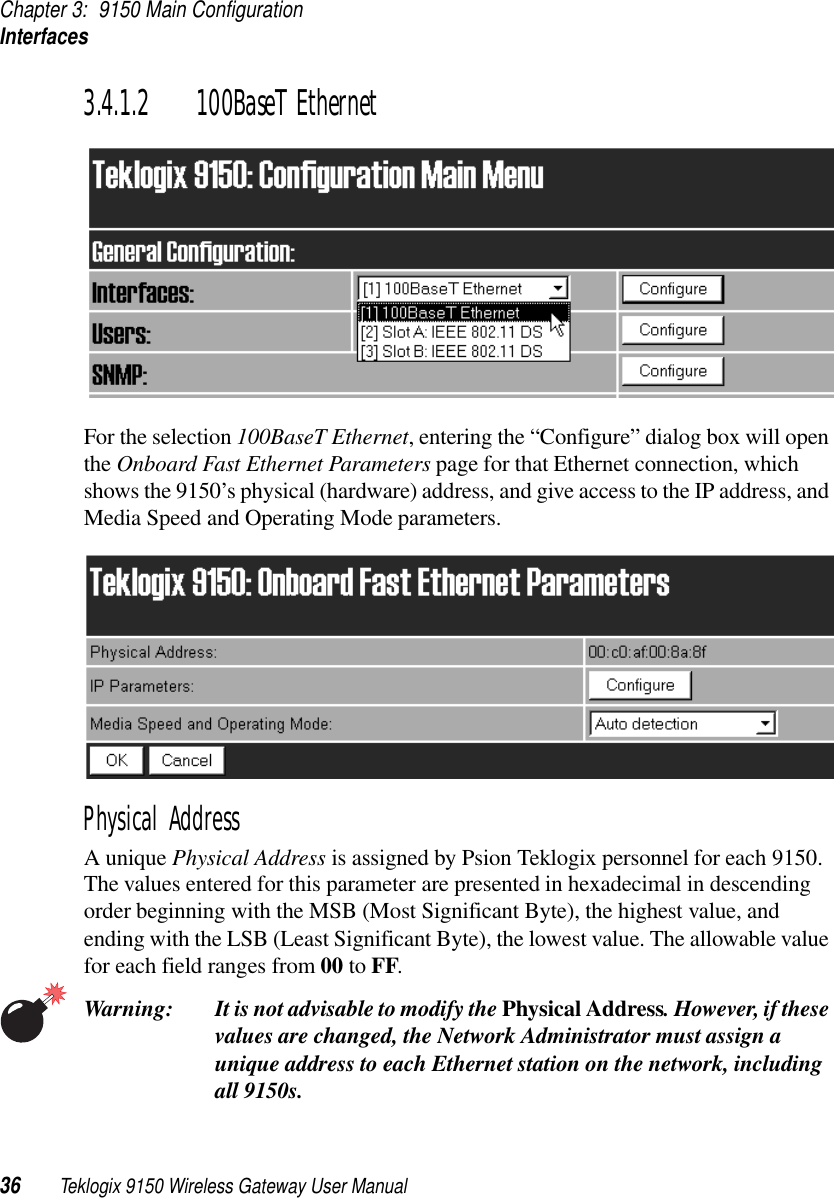
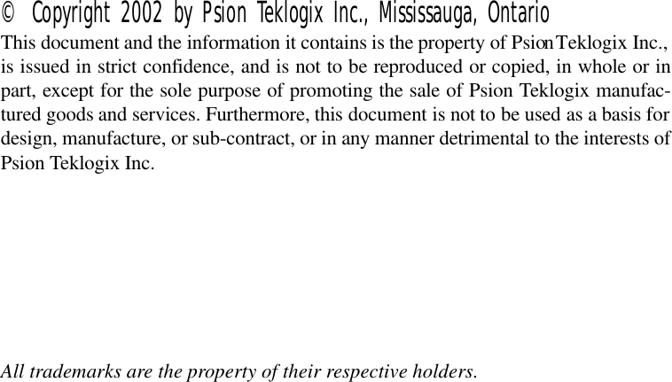
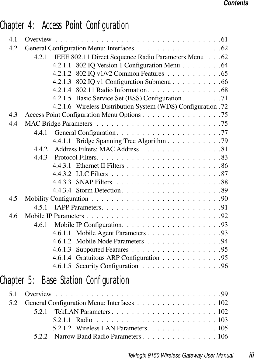
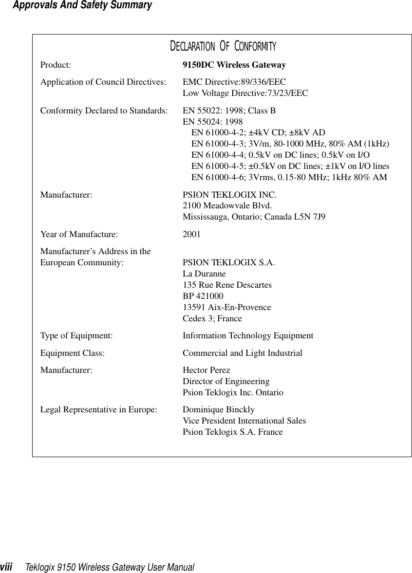
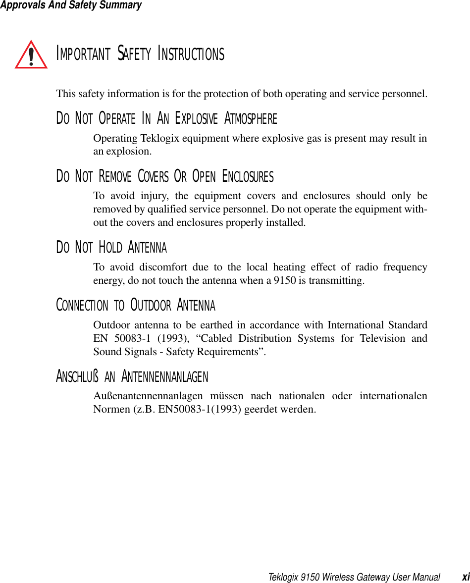
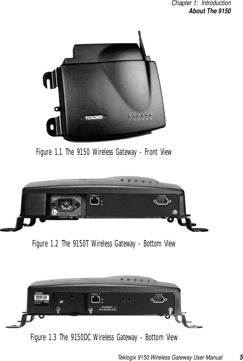
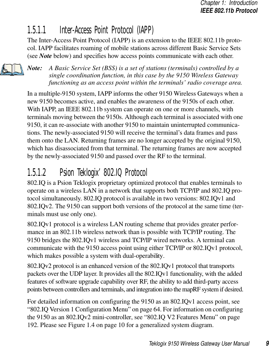
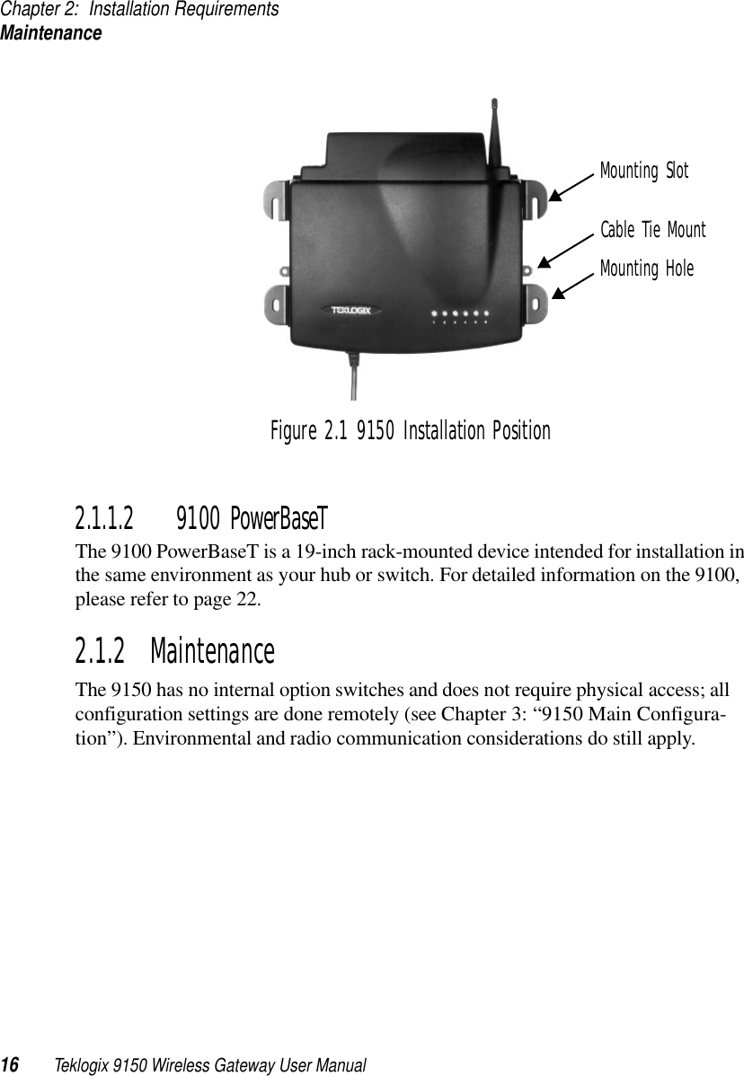
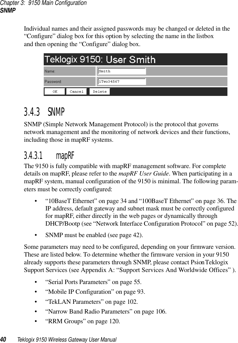
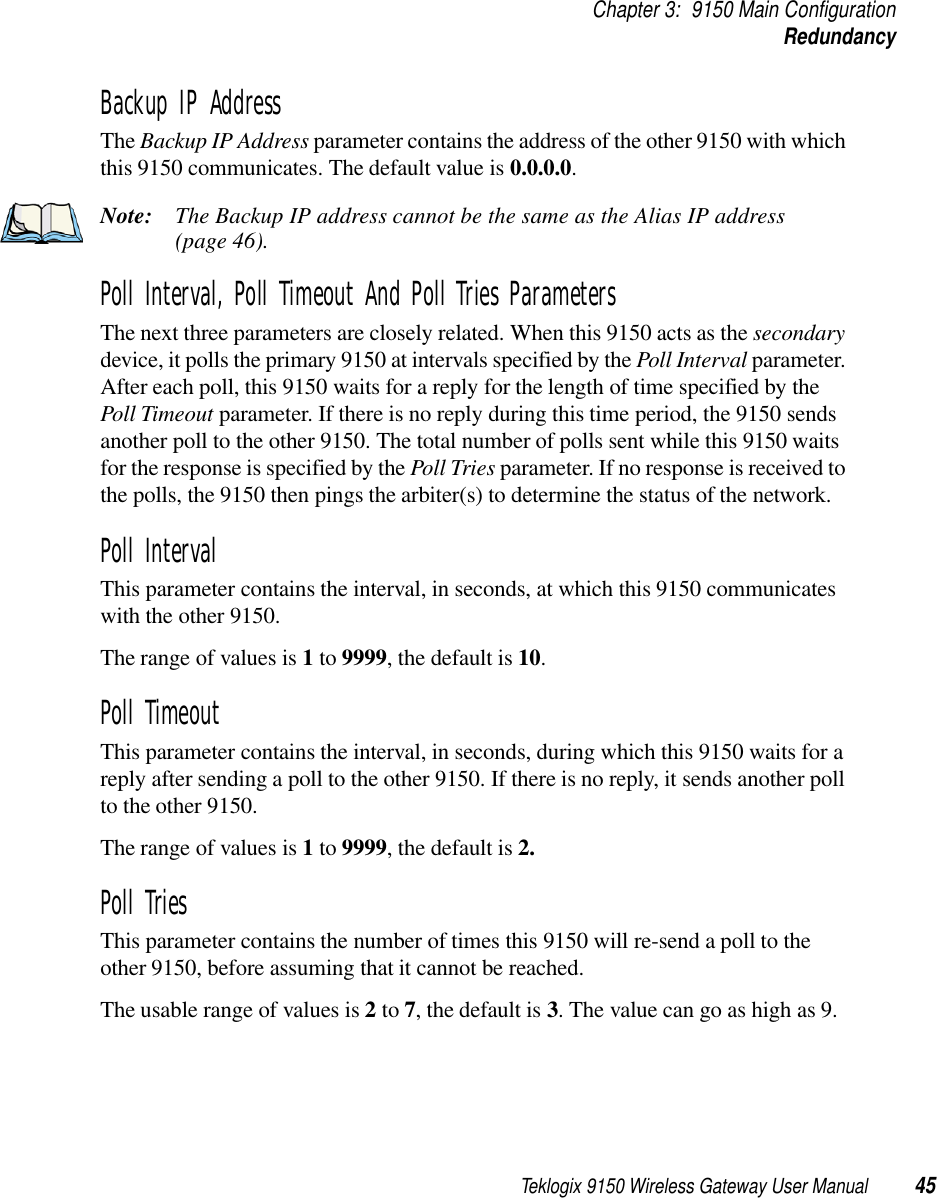
![Teklogix 9150 Wireless Gateway User Manual 39Chapter 3: 9150 Main ConfigurationUsers3.4.2 UsersThe Users option provides security for access to the 9150 Configuration menus. New individuals and their passwords can be added by selecting “[#] Create New” in the listbox before entering the “Configure” dialog box. NameThe name should be comprised of alphanumeric characters only, is case-sensitive, and should not contain spaces. The minimum length of the name is 4 characters, the maximum length is 32 characters. The default value is user. PasswordThe password should be comprised of alphanumeric characters only, is case-sensitive, and should not contain spaces. The minimum length of the password is 6 characters, the maximum length is 32 characters. The default value is 123456.](https://usermanual.wiki/Psion/RA2020.USERS-MANUAL-1/User-Guide-400310-Page-54.png)
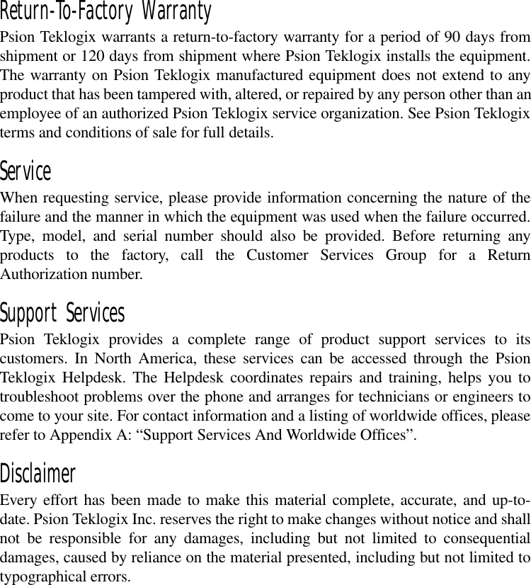
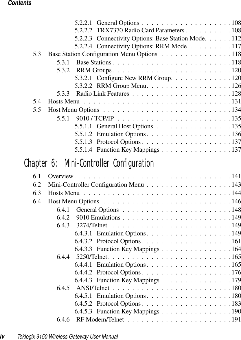
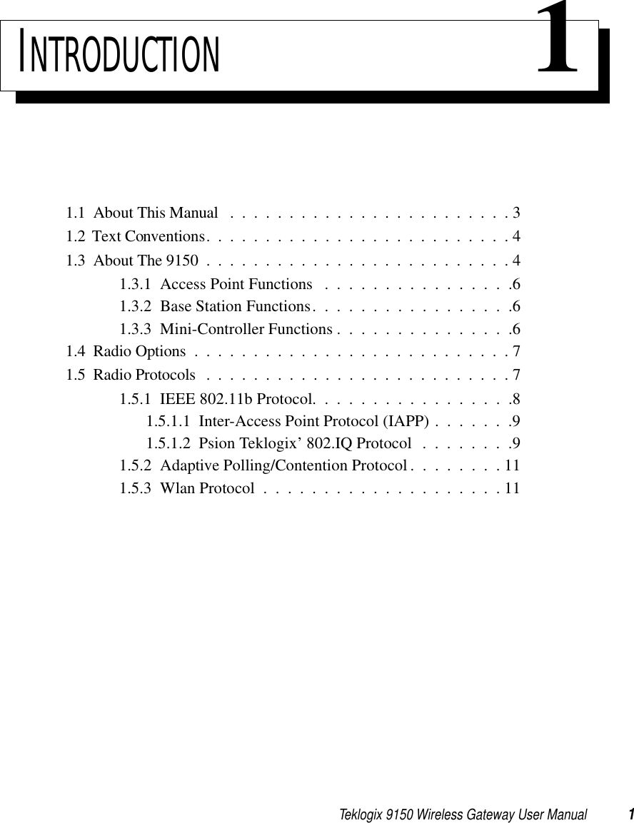
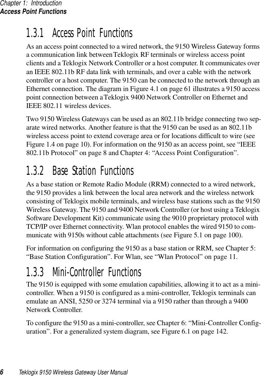
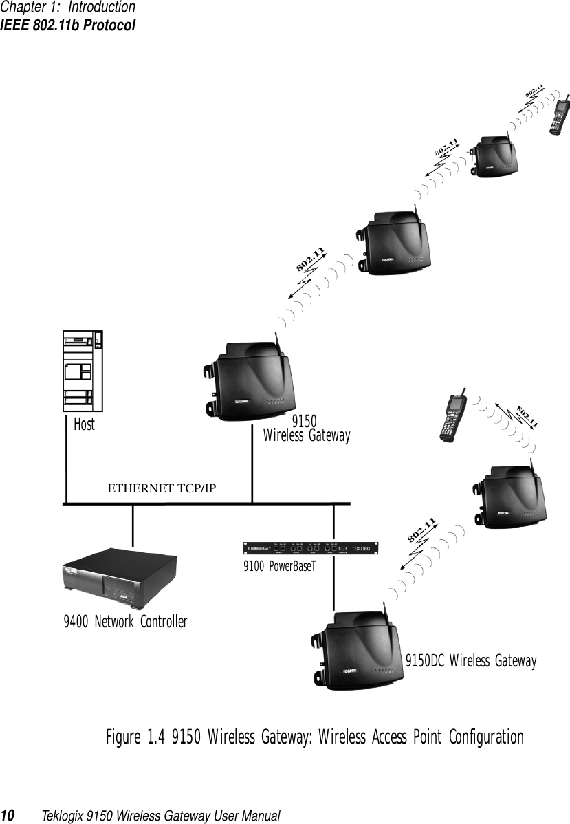
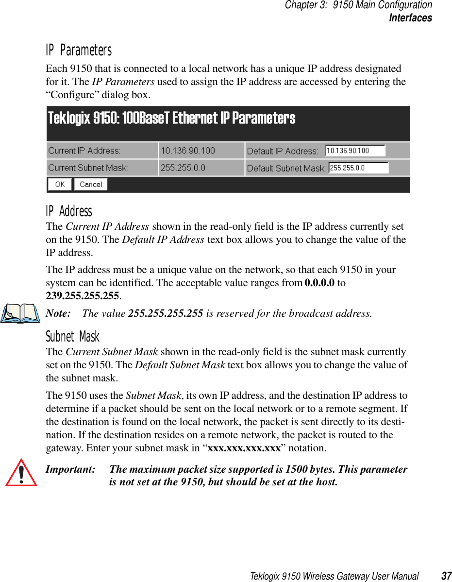
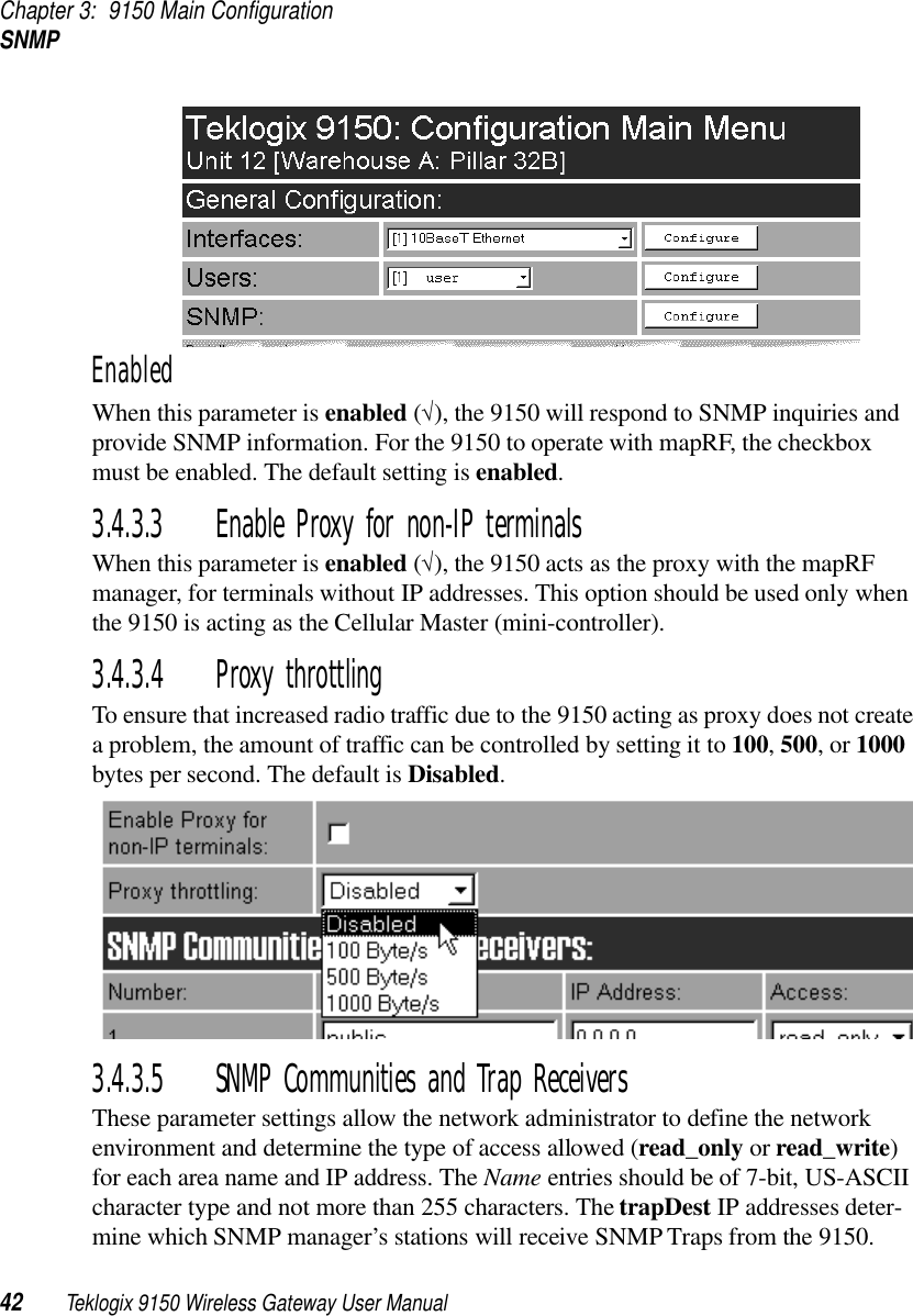
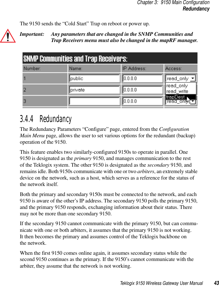
![Teklogix 9150 Wireless Gateway User Manual 41Chapter 3: 9150 Main ConfigurationSNMPThe SNMP “Configure” page, entered from the Configuration Main Menu page, allows various network management parameters to be set or changed.3.4.3.2 System ParametersName, Contact, LocationThe entries in these parameters set the name, contact and location identifiers for this specific 9150 Wireless Gateway. The entries should be of 7-bit, US-ASCII character type and not more than 78 characters. The name and location are then shown as the sub-heading of each Configuration page. In the following example the identifier appears as “Unit 12 [Warehouse A: Pillar 32B]”.](https://usermanual.wiki/Psion/RA2020.USERS-MANUAL-1/User-Guide-400310-Page-56.png)
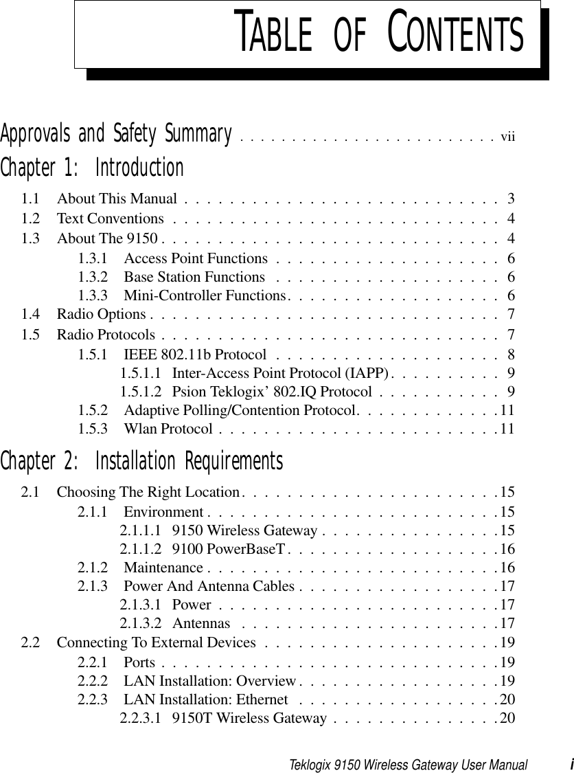
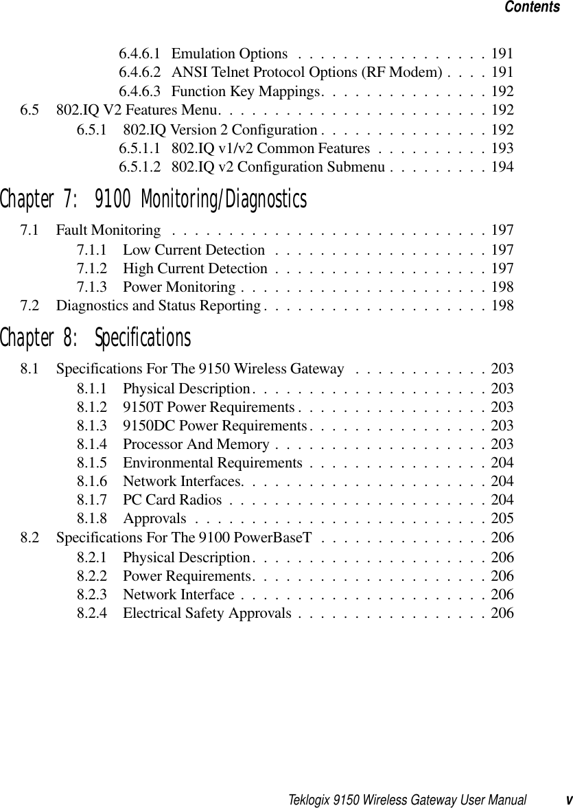
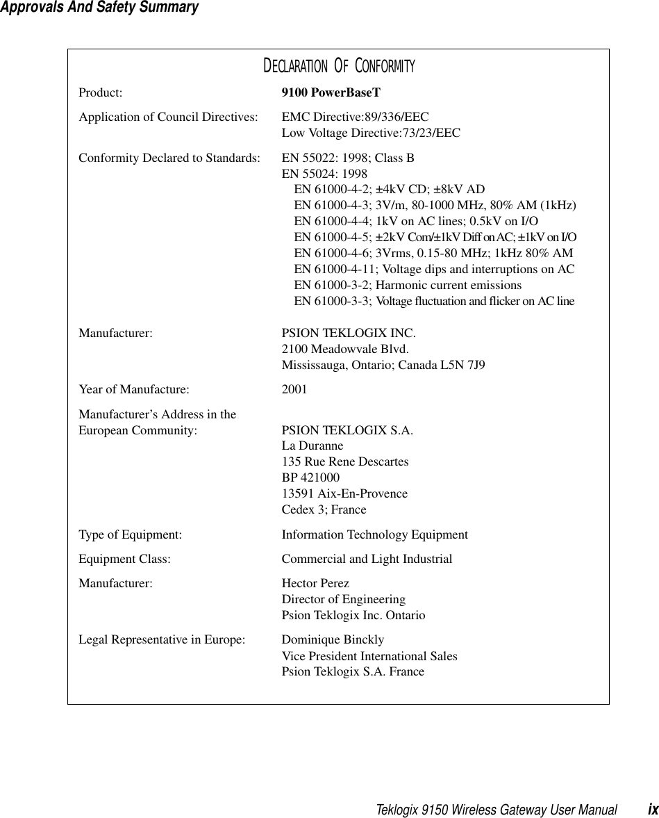
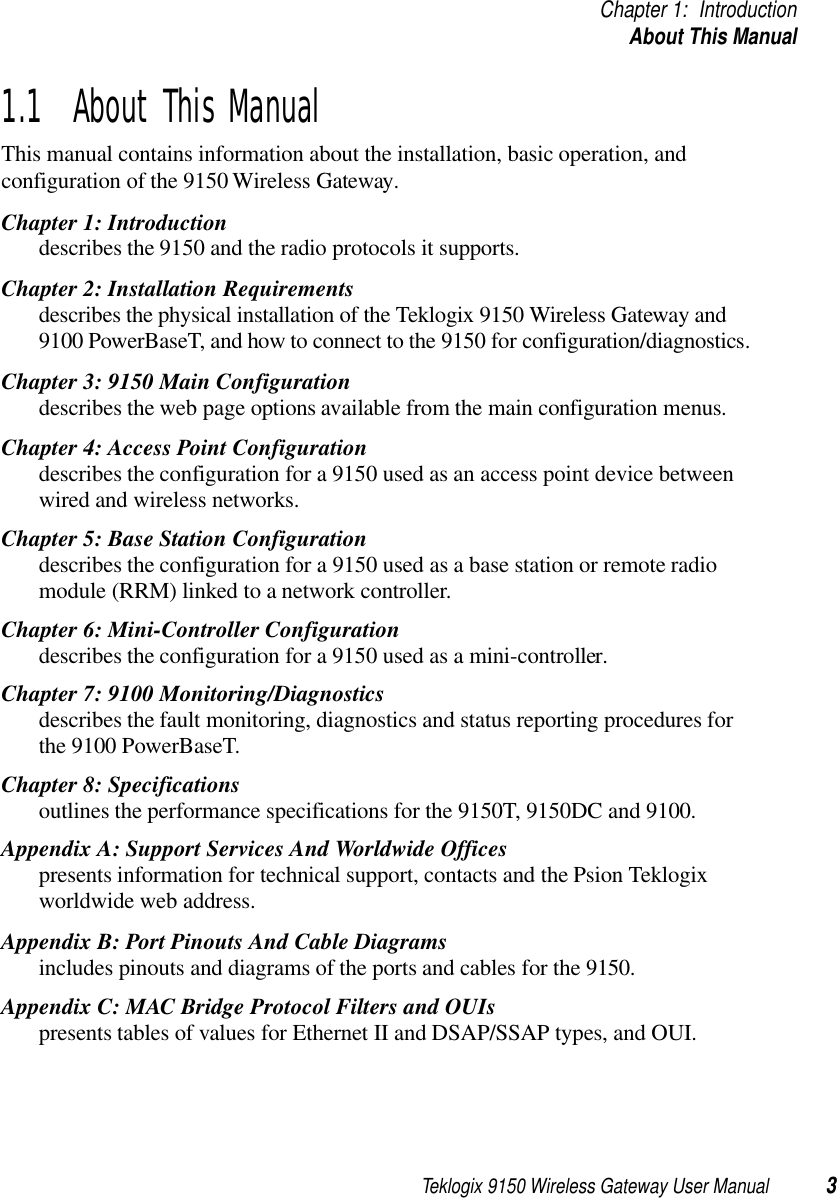
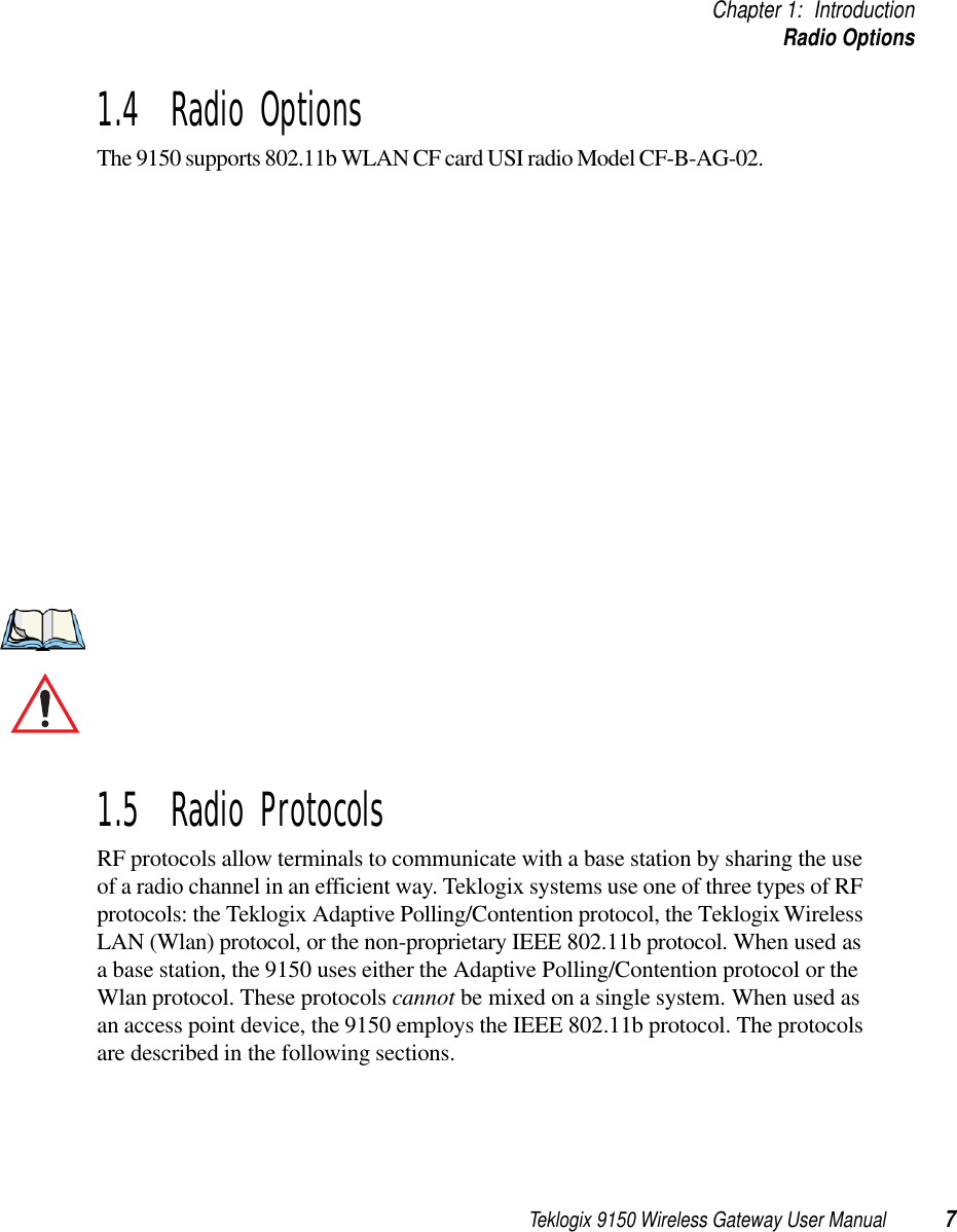
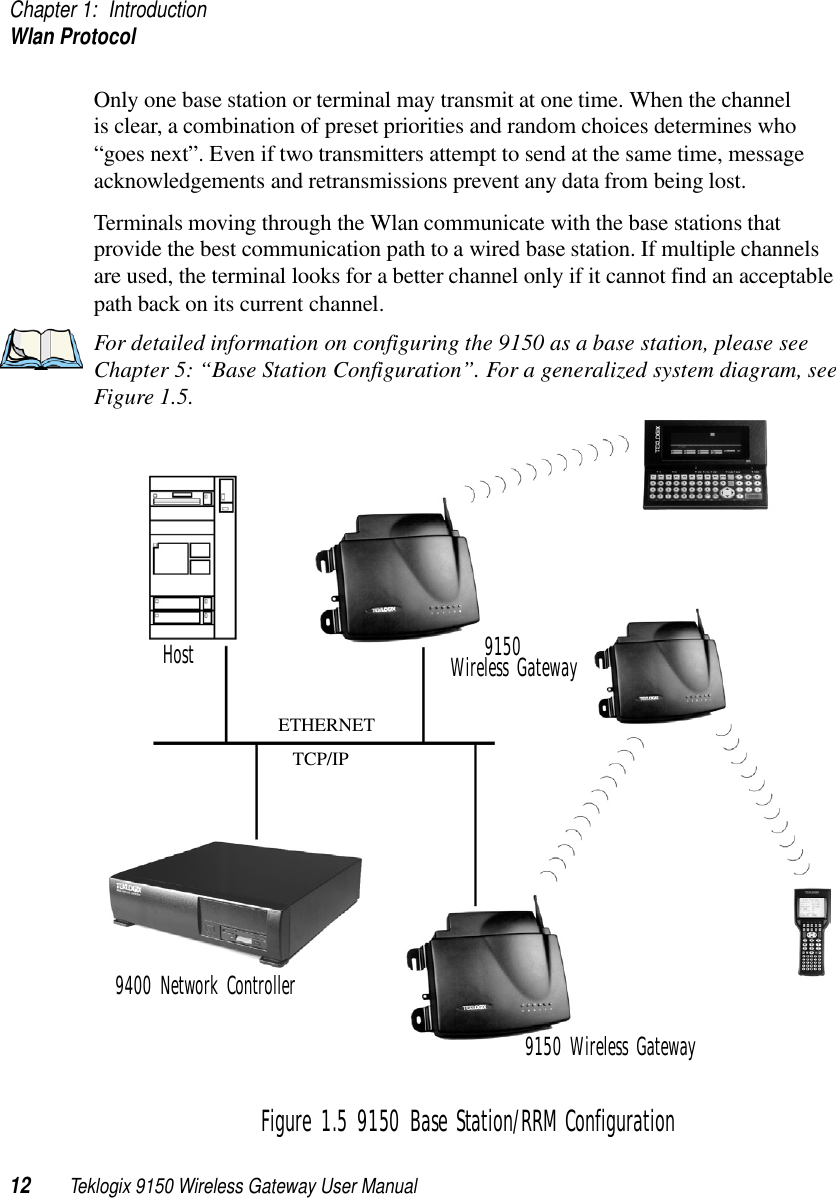
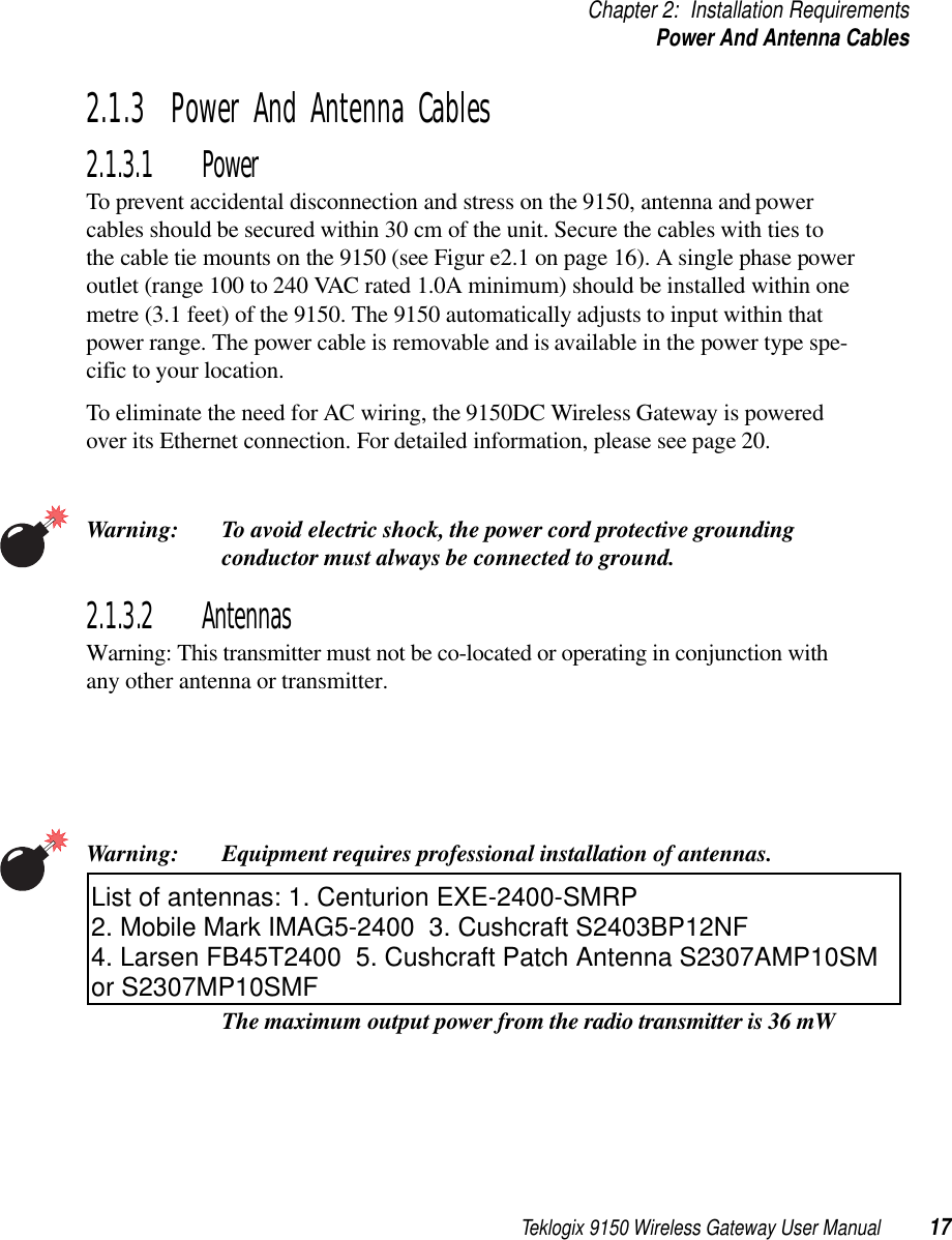
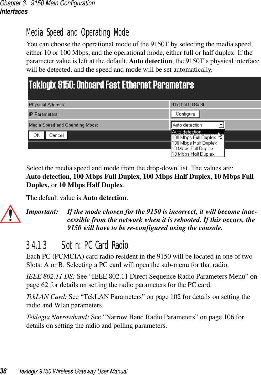
![Teklogix 9150 Wireless Gateway User Manual 49Chapter 3: 9150 Main ConfigurationTCP/IP Parameters3.4.6.1 Route TableRouting Table The routing table is used when the 9150 and the host are not connected directly on a single physical network segment. Packets are routed between network segments to the network connections, depending on the packets’ destination addresses and on the contents of the 9150’s Host and Routing tables.To add an entry to the 9150’s routing table, select “Configure” beside “[#] Add Entry” in the listbox. This will open the New Routing Table Entry menu.New Routing Table EntryEntry NameThis is the designated name of the entry.Destination TypeSelect a destination type for this entry from the drop-down list, either Host or Net.Router IP AddressEnter the router’s IP address in this textbox. This device must be on the same subnet as the 9150, and must be capable of sending packets to the host. If the host is on the same subnet as the 9150, enter its address here and in the Destination IP Address textbox.Destination IP AddressEnter the IP address of the host. If the host is on the same subnet as the 9150, enter its address here and in the Router IP Address textbox.](https://usermanual.wiki/Psion/RA2020.USERS-MANUAL-1/User-Guide-400310-Page-64.png)
![Chapter 3: 9150 Main ConfigurationTCP/IP Parameters50 Teklogix 9150 Wireless Gateway User Manual3.4.6.2 Host TableIf no external DNS server is available, the 9150 may resolve host names to IP addresses using its internal host table.Host TableHosts are added to the table by selecting “Configure” beside “[#] Add Entry” in the listbox. This will open the New Host Table Entry menu where a new host name and IP address can be entered.An existing host’s name and IP address may be edited in the Host Table Entry menu by selecting “Configure” beside the host name in the listbox. The host may also be deleted from the table. When choosing to delete a host, you will be prompted for confirmation of the deletion, which will give you the opportu-nity to cancel the action.](https://usermanual.wiki/Psion/RA2020.USERS-MANUAL-1/User-Guide-400310-Page-65.png)