Psion RA2020 WIRELESS GATEWAY User Manual 80440
Psion Inc WIRELESS GATEWAY 80440
UserManual.wiki
>
Psion
>
RA2020 User Manual
>
USERS MANUAL 2
Contents
1.
ANTENNA CO LOCATION WARNING
2.
FCC STATEMENT INFO TO USERS
3.
LETTER OF PHOTO
4.
USERS MANUAL 1
5.
USERS MANUAL 2
6.
USERS MANUAL 3
USERS MANUAL 2
Navigation menu
Upload a User Manual
Namespaces
Wiki Guide
HTML
PDF
Info
Views
User Manual
Discussion / Help
Navigation

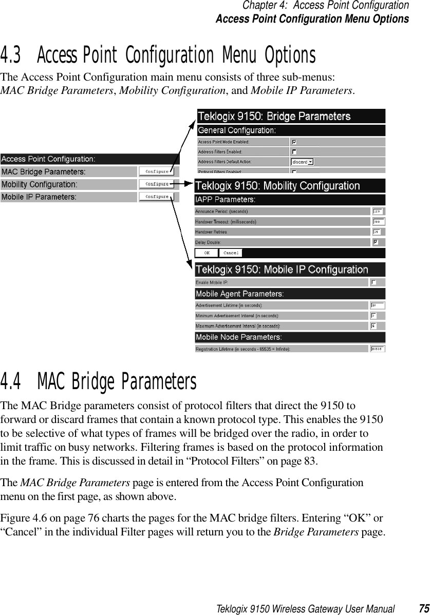
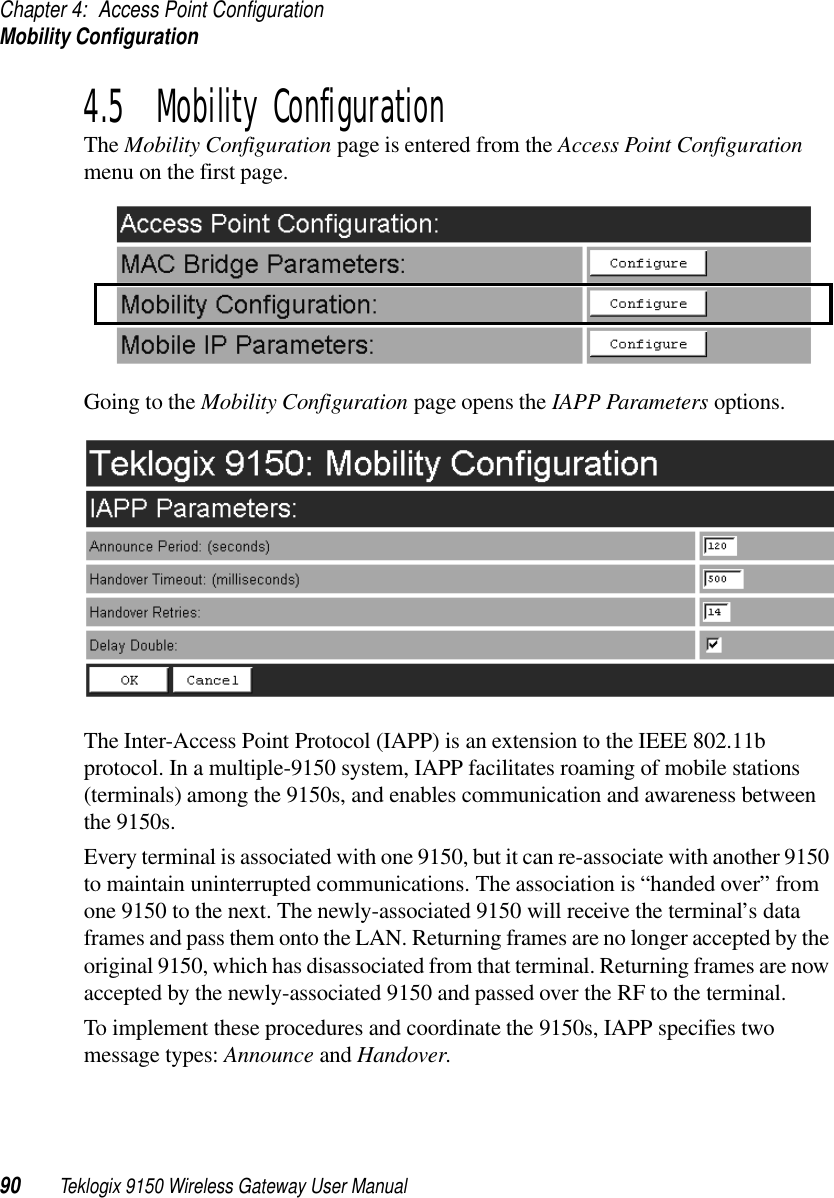
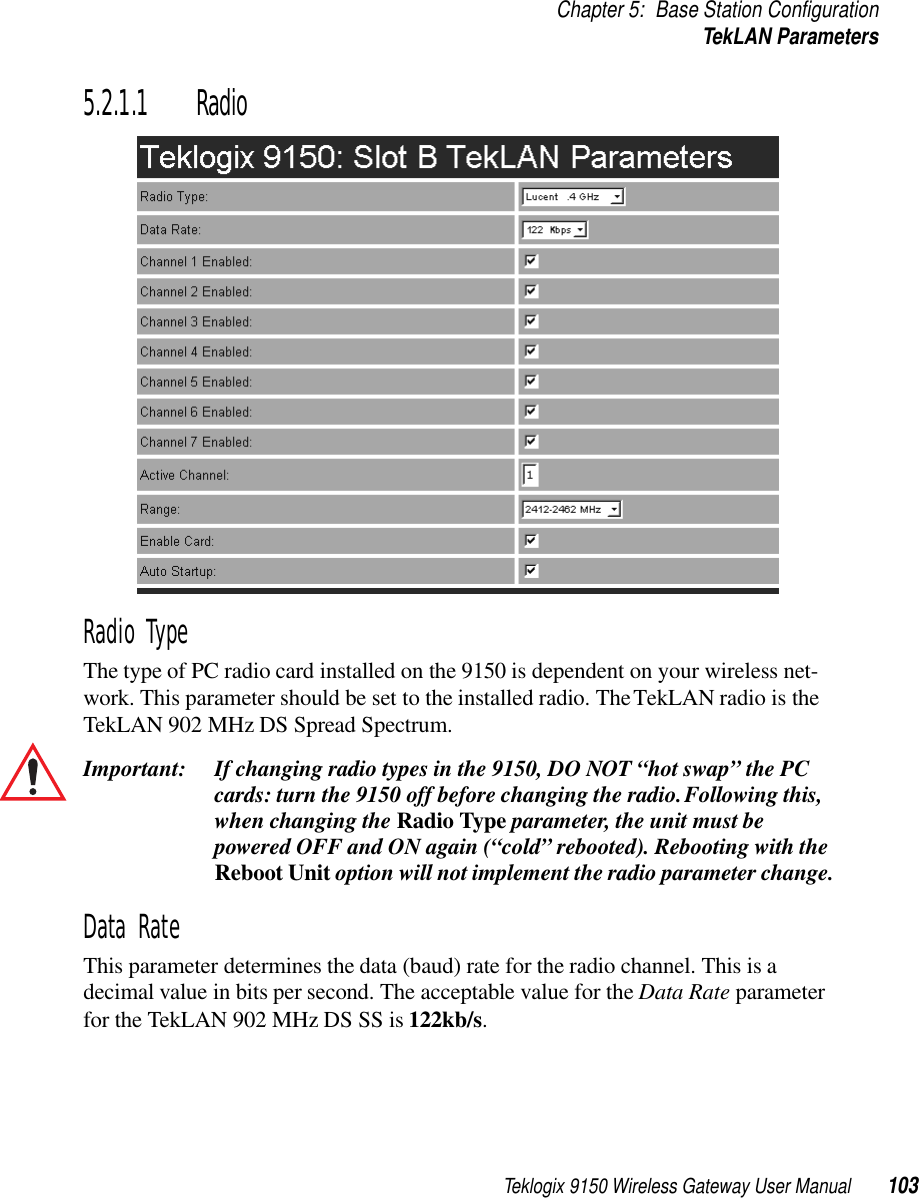
![Teklogix 9150 Wireless Gateway User Manual 85Chapter 4: Access Point ConfigurationProtocol FiltersFigure 4.8 Protocol Filters Main Menu And Sub-menusNew filters can be added by selecting “[#] Create New” in the listbox before enter-ing the “Configure” dialog box. Once a filter is created, the option to delete it can be found on its configuration page (for example, see “Ethernet II Filters” on page 86). When choosing to delete a filter, you will be prompted for confirmation of the dele-tion, which will give you the opportunity to cancel the action.](https://usermanual.wiki/Psion/RA2020.USERS-MANUAL-2/User-Guide-400311-Page-35.png)