Contents
USERS MANUAL 2
Teklogix 9150 Wireless Gateway User Manual 51
Chapter 3: 9150 Main Configuration
TCP/IP Parameters
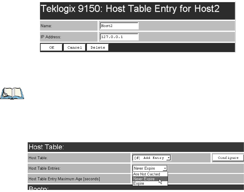
Name
This is the designated name of the host.
Note: The name must not contain space characters.
IP Address
This is the assigned IP address for the host.
Host Table Entries
This parameter allows you to determine the behaviour of the host name cache. The
allowable settings are: Expire, Are Not Cached, and Never Expire. If Expire is
selected, a timeout length determines how long the cached entries will remain in the
table (see parameter, “Host Table Entry Maximum Age”, below).
The default setting is Never Expire.
Host Table Entry Maximum Age (seconds)
This parameter allows you to set the expiry time limit (in seconds) for the host name
cache when the Host Table Entries parameter is set to Expire.
The minimum allowable value is 30. The default value is 600.
Chapter 3: 9150 Main Configuration
TCP/IP Parameters
52 Teklogix 9150 Wireless Gateway User Manual
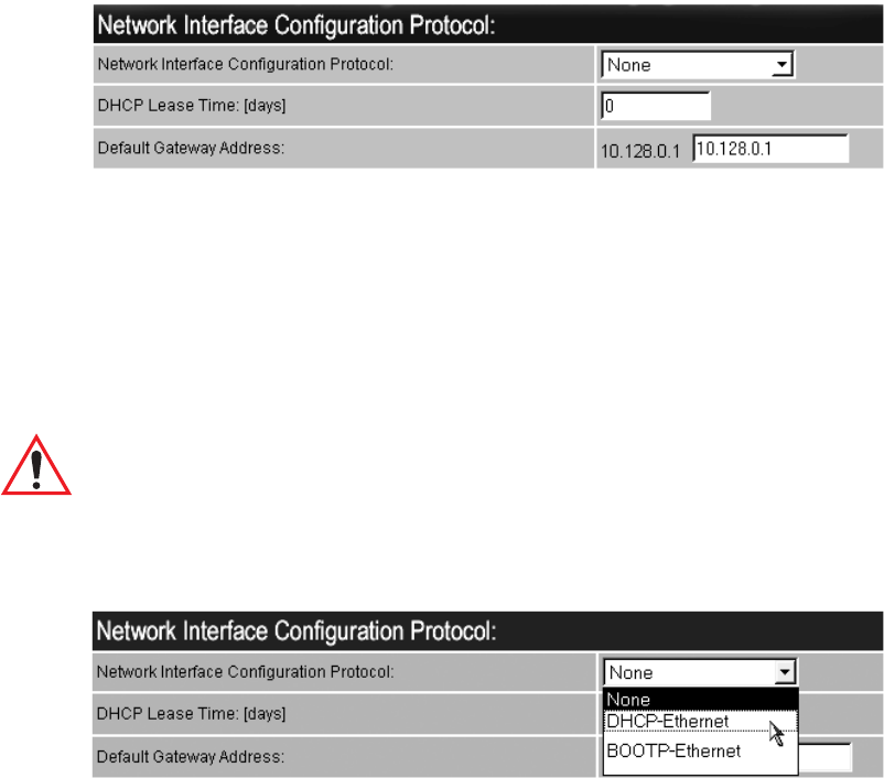
3.4.6.3 Network Interface Configuration Protocol
The 9150 has designated default IP addresses for itself and the network Gateway.
Alternatively, the IP address of the 9150 can be assigned by either a DHCP Server or
BOOTP Server, if one is appropriately configured on the network.
If either the DHCP or BOOTP option is chosen from the Network Interface Config-
uration Protocol drop-down list, the 9150 will broadcast a request to the appropriate
server, as described in the following sections.
The default setting is None.
Important: Once the 9150 is configured and rebooted the first time, the
Network Interface Configuration Protocol parameter should be
disabled (set to None), unless the 9150 obtains its IP address from
a DHCP or bootp server, or the system administrator intends to
update the software through bootp.
DHCP
The Dynamic Host Configuration Protocol provides a mechanism for allocating IP
addresses dynamically so that addresses can be reused when hosts no longer require
them, and also ensures that a particular address is not duplicated. The 9150 can
obtain the following parameters from an appropriately configured DHCP Server: IP
address, subnet mask, and IP address lease time (see DHCP Lease Time on
page 53). The DNS Domain Name/Server IP addresses (see page 54) and SNTP
Server IP address (see page 47) will also be requested from the DHCP Server.

Teklogix 9150 Wireless Gateway User Manual 53
Chapter 3: 9150 Main Configuration
TCP/IP Parameters
Select DHCP for the 9150 to automatically broadcast a request for DHCP-
configured addresses to all hosts on the local Ethernet network.
BOOTP
The primary purpose of the Bootstrap Protocol (BOOTP) is to assign a designated
IP address to the appropriate 9150 on the network, and to update the 9150 software.
When the BOOTP option is selected from the Network Interface Configuration Pro-
tocol drop-down list, the 9150 automatically broadcasts a request for IP address,
subnet mask, and flash image file name, to all hosts on the local Ethernet network,
including the Wireless Distribution System (WDS) links.
BOOTP Servers search the bootptab files for a hardware address match for the 9150
that initiated the request for address. (Bootptab files list each hardware address with a
corresponding IP address, and the flash image file.) The host with a matching hard-
ware address in its bootp table replies to the request, sending the appropriate IP
address and, if needed, the image file to the 9150.
Software Upgrade Using TFTP
The 9150 software may be upgraded by using a TFTP server instead of BOOTP.
Contact the TFTP server and download the new image file by connecting the 9150 to
a PC console (for details refer to page29) and entering the following command line:
>net tftp <servername><imagefile>
The image file will be loaded after the 9150 is rebooted.
Note: This command is available for all version C releases of software, and for
version B55. Do not use if B52 is the current version of software.
DHCP Lease Time
This parameter defines the length of time (in days) that the 9150 is requesting for the
lease on its IP address and subnet mask. The default setting is 0 (zero), which
requests the maximum lease time configured at the DHCP Server.
Default Gateway Address
The Default Gateway Address creates an identifiable communication link between
the 9150 and a network other than the one to which the 9150 is directly wired. The
Gateway Address shown in the read-only field is the address currently assigned by
the network administrator. The text box allows you to change the value of the address.
Chapter 3: 9150 Main Configuration
TCP/IP Parameters
54 Teklogix 9150 Wireless Gateway User Manual
The acceptable values for the Default Gateway IP address range from 0.0.0.0 to
239.255.255.255.
Note: Setting the Gateway IP Address to 0.0.0.0 disables this feature.
A communication link will not exist between sub-networks.
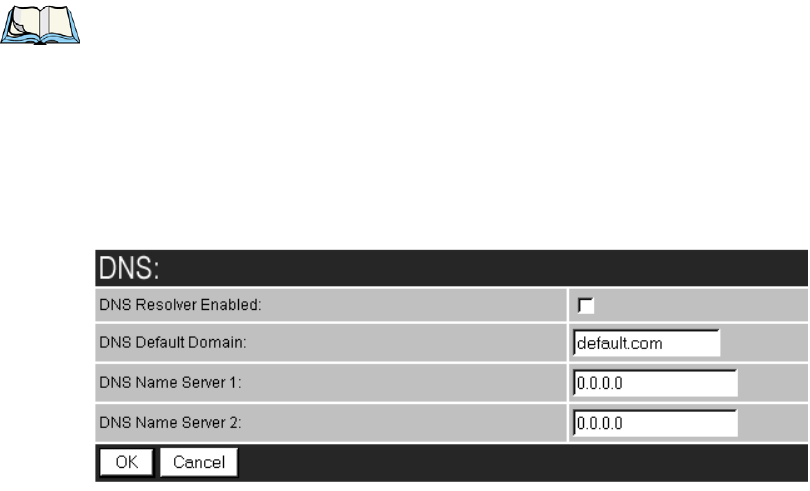
3.4.6.4 DNS
Domain Name System allows users to locate destinations on the TCP/IP network by
domain (host) name. The DNS server maintains a database of host names and their
corresponding IP addresses. For example, if the server was presented with the name
“www.teklogix.com”, it would return the IP address: “207.219.2.3”.
DNS Resolver Enabled
When this parameter is enabled (√), the 9150 will use the DNS Name Server identi-
fied by the IP address entered in the DNS Name Server parameter.
DNS Default Domain
This is the default domain name for this 9150.
DNS Name Server 1
This is the IP address of the first designated DNS Name Server. The DNS Resolver
will first contact this server to resolve a name query. If the query isn’t resolved, the
DNS Resolver will then contact the second DNS Name Server.
DNS Name Server 2
This is the IP address of the second designated DNS Name Server.
Teklogix 9150 Wireless Gateway User Manual 55
Chapter 3: 9150 Main Configuration
Serial Ports Parameters
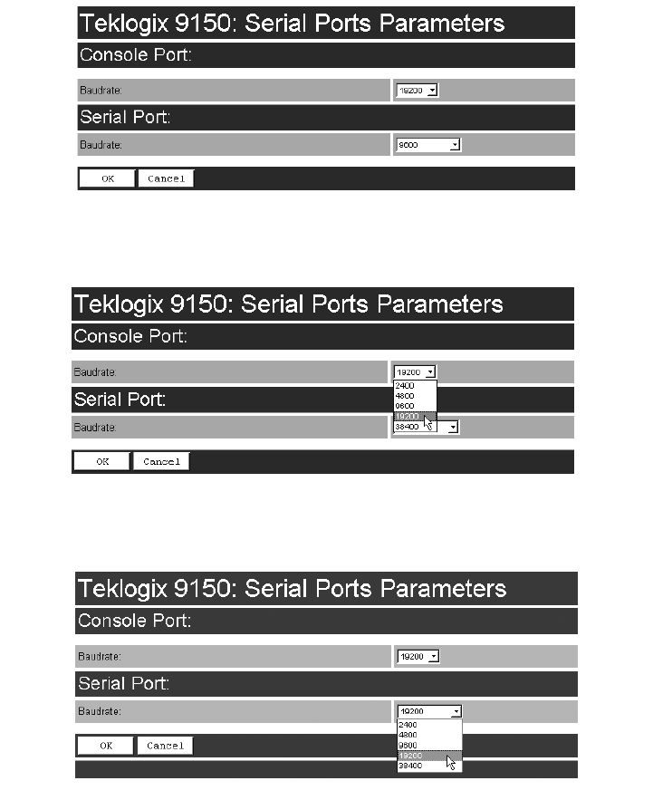
3.4.7 Serial Ports Parameters
These parameters allow you to set the baud rates for the console port and the serial
port. The Serial Ports Parameters “Configure” page, is entered from the Configura-
tion Main Menu page.
3.4.7.1 Console Port
Baudrate: The default baud rate for the console port is 19.2kb/s.
3.4.7.2 Serial Port
Baudrate: The default baud rate for the serial port is 19.2kb/s.
Chapter 3: 9150 Main Configuration
Access Point/Base Station/Mini-Controller Menus
56 Teklogix 9150 Wireless Gateway User Manual
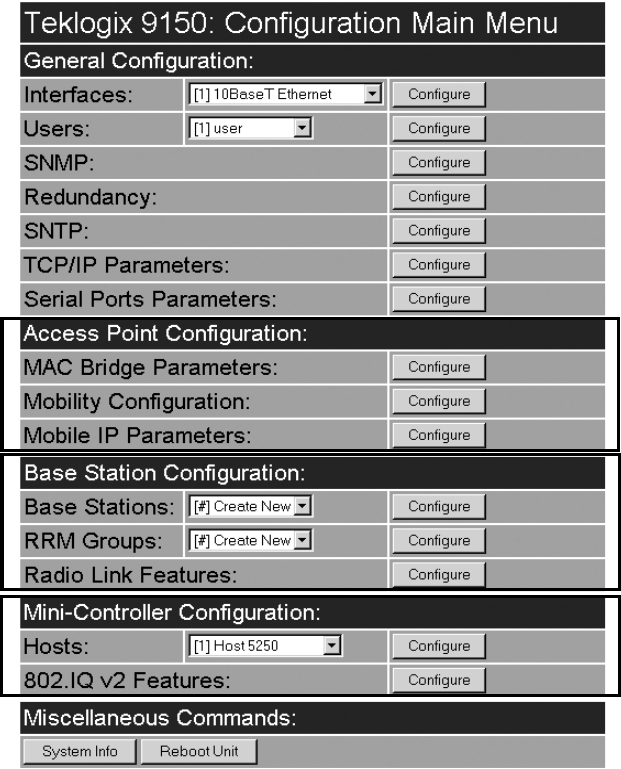
3.5 Access Point/Base Station/Mini-Controller Menus
The 9150 is capable of operating as a transparent bridge (access point) between the
wireless and wired networks, and also as a mini-controller or base station. For these
operations, the parameters in these pages must be set appropriately. For detailed
information on the sub-menus and to set up the 9150 as a base station, see
Chapter 5: “Base Station Configuration”. To configure an access point device,
see Chapter 4: “Access Point Configuration”. To configure the 9150 as a mini-
controller, see Chapter 6: “Mini-Controller Configuration”.
Teklogix 9150 Wireless Gateway User Manual 57
Chapter 3: 9150 Main Configuration
Miscellaneous Commands Menu Options
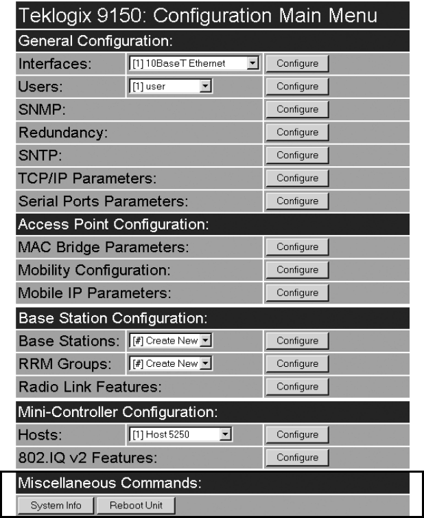
3.6 Miscellaneous Commands Menu Options
There are two miscellaneous commands: System Info and Reboot Unit.
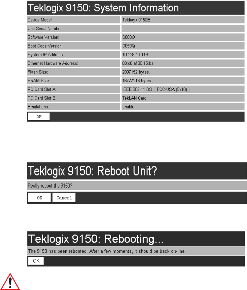
3.6.1 System Info
The System Information, hardware and software, for the 9150 Wireless Gateway
unit is detected automatically and summarized in this page. The screen is shown on
page 58.
Chapter 3: 9150 Main Configuration
Reboot Unit
58 Teklogix 9150 Wireless Gateway User Manual
3.6.2 Reboot Unit
This option opens a dialog box which allows you to remotely “warm” reboot
the 9150.
If the OK button is chosen, the 9150 will be rebooted, the LEDs will turn off
momentarily, and the following message will be received:
Important: If changing radio types in the 9150, and therefore changing the
Radio Type parameter (see page 103), the unit must be powered
OFF and ON again (“cold” rebooted). Rebooting with the Reboot
Unit option will not implement the radio parameter change.

Teklogix 9150 Wireless Gateway User Manual 59
ACCESS POINT CONFIGURATION 4
4.1 Overview.................................61
4.2 General Configuration Menu: Interfaces. . ...............62
4.2.1 IEEE 802.11 Direct Sequence Radio Parameters Menu . . . . 62
4.2.1.1 802.IQ Version 1 Configuration Menu . . . . . . . . 64
4.2.1.2 802.IQ v1/v2 Common Features . . . . . . . . . . . 65
4.2.1.3 802.IQ v1 Configuration Submenu . . . . . . . . . . 66
4.2.1.4 802.11 Radio Information . . . . . . . . . . . . . . . 68
4.2.1.5 Basic Service Set (BSS) Configuration . . . . . . . . 71
4.2.1.6 Wireless Distribution System (WDS) Configuration . 72
4.3 Access Point Configuration Menu Options ...............75
4.4 MAC Bridge Parameters. . . ......................75
4.4.1 General Configuration . . . . . . . . . . . . . . . . . . . . 77
4.4.1.1 Bridge Spanning Tree Algorithm . . . . . . . . . . . 79
4.4.2 Address Filters: MAC Address . . . . . . . . . . . . . . . 81
4.4.3 Protocol Filters. . . . . . . . . . . . . . . . . . . . . . . . 83
4.4.3.1 Ethernet II Filters . . . . . . . . . . . . . . . . . . . 86
4.4.3.2 LLC Filters ......................87
4.4.3.3 SNAP Filters. . . . . . . . . . . . . . . . . . . . . . 88
4.4.3.4 Storm Detection....................89
4.5 Mobility Configuration .........................90
4.5.1 IAPP Parameters . . . . . . . . . . . . . . . . . . . . . . . 91
4.6 Mobile IP Parameters ..........................92
4.6.1 Mobile IP Configuration . . . . . . . . . . . . . . . . . . . 93
4.6.1.1 Mobile Agent Parameters...............93
4.6.1.2 Mobile Node Parameters ...............94
60 Teklogix 9150 Wireless Gateway User Manual
4.6.1.3 Supported Features. . . . . . . . . . . . . . . . . . .95
4.6.1.4 Gratuitous ARP Configuration. . . . . . . . . . . . .95
4.6.1.5 Security Configuration . . . . . . . . . . . . . . . . .96
Teklogix 9150 Wireless Gateway User Manual 61
Chapter 4: Access Point Configuration
Overview
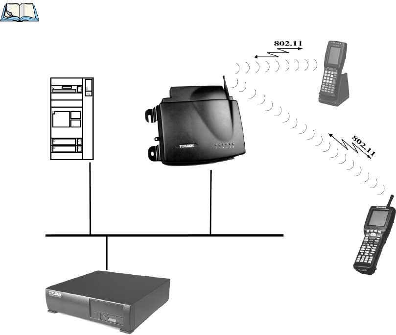
4.1 Overview
The 9150 can operate as an access point device between IEEE 802.11b wireless
and wired networks. Using IEEE 802.11b protocol, the 9150 provides a transparent
bridge between Teklogix or client terminals and a network controller or host. For an
overview of IEEE 802.11b, please refer to “IEEE 802.11b Protocol” on page 8.
For operation as an access point, the parameters in the following pages must be
set appropriately.
Note: The 9150 main parameters should first be set up as described in
Chapter 3: “9150 Main Configuration”.
Figure 4.1 9150 Access Point Configuration
ETHERNET
TCP/IP
9150
Wireless Gateway
Network Controller
9400
Chapter 4: Access Point Configuration
General Configuration Menu: Interfaces
62 Teklogix 9150 Wireless Gateway User Manual
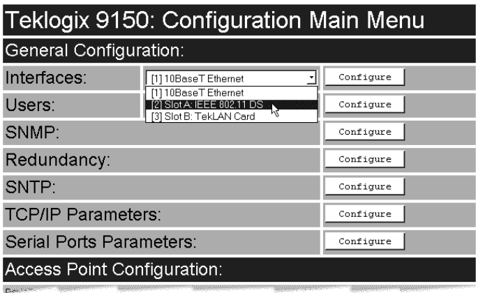
4.2 General Configuration Menu: Interfaces
The pull-down menu shown for the Interfaces option indicates which interfaces have
been detected in use by the 9150, including any 802.11 PCMCIA radio:
• IEEE 802.11 DS: USI WaveLAN IEEE 802.11 DSSS 2.4 GHz.
Selecting IEEE 802.11 DS radio type from the drop-down list and entering “Config-
ure” will open the radio parameters page for that radio.
4.2.1 IEEE 802.11 Direct Sequence Radio Parameters Menu
When the USI WaveLAN IEEE 802.11 DSSS 2.4 GHz PCMCIA card is installed
in the 9150, the IEEE 802.11 Direct Sequence Radio Parameter sub-menu shown on
the next page is opened from the Interfaces main menu.
Teklogix 9150 Wireless Gateway User Manual 63
Chapter 4: Access Point Configuration
IEEE 802.11 Direct Sequence Radio Parameters Menu
Chapter 4: Access Point Configuration
IEEE 802.11 Direct Sequence Radio Parameters Menu
64 Teklogix 9150 Wireless Gateway User Manual
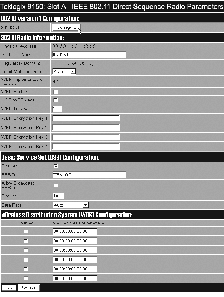
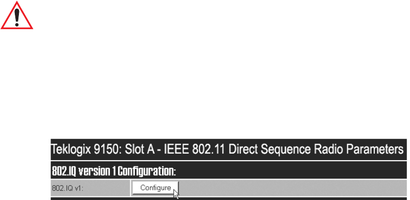
4.2.1.1 802.IQ Version 1 Configuration Menu
This parameter accesses the 802.IQv1 sub-menu that enables the Psion Teklogix
proprietary 802.11b enhanced protocol, as described in “802.IQ v1 Sub-Menu”,
below, and in “Psion Teklogix’ 802.IQ Protocol” on page 9. For information on
802.IQv2, please refer to “802.IQ Version 2 Configuration” on page 192.
802.IQ v1 Sub-Menu
802.IQ is a Psion Teklogix proprietary optimized protocol that enables terminals to
operate on a wireless LAN in a network that supports both TCP/IP and 802.IQ pro-
tocol simultaneously.
802.IQv1 protocol is a wireless LAN protocol that provides greater performance in
an 802.11b wireless network than is possible with TCP/IP.
The 9150 bridges the 802.IQv1 wireless and TCP/IP wired networks. A terminal can
communicate with the 9150 access point using either TCP/IP or 802.IQv1 protocol.
Important: 802.IQ should only be enabled on wired 9150s.
Do not configure 802.IQ on wired 9150s bridging networks, since
802.IQ beacons would be sent through the WDS link from one
network to the other (see “Wireless Distribution System (WDS)
Configuration” on page 72).
The 802.IQv1 page is entered from the 802.IQ version 1 Configuration menu on the
IEEE 802.11 Direct Sequence Radio Parameters page.
Teklogix 9150 Wireless Gateway User Manual 65
Chapter 4: Access Point Configuration
IEEE 802.11 Direct Sequence Radio Parameters Menu
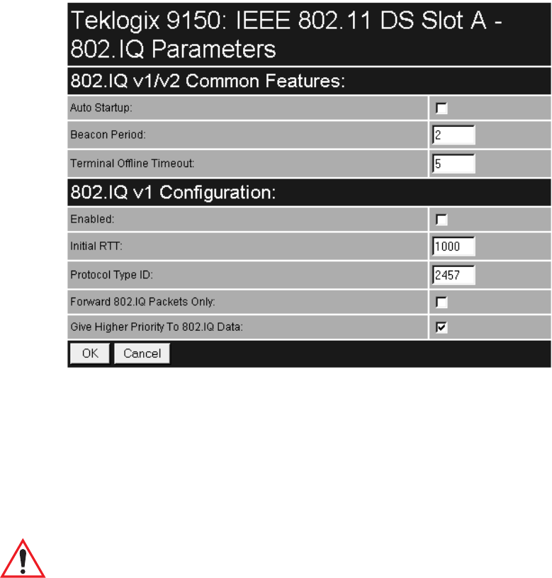
4.2.1.2 802.IQ v1/v2 Common Features
Auto Startup
This parameter enables ( √ ) 802.IQ immediately when the 9150 is rebooted. When
the 9150 is operating as a base station under a network controller or a 9150 mini-
controller, this parameter must be disabled.
The default value is disabled.
Important: If Auto Startup is set incorrectly, terminals may not operate correctly.
Beacon Period
An 802.IQ beacon is a broadcast sent out to all 802.IQ-enabled terminals. The
beacon allows terminals to determine when they have roamed between base stations.
It enables a terminal to determine whether or not the base station or controller was
Chapter 4: Access Point Configuration
IEEE 802.11 Direct Sequence Radio Parameters Menu
66 Teklogix 9150 Wireless Gateway User Manual
rebooted and, if so, how to recover. If the controller was rebooted, the terminal
closes all sessions and fully re-initializes. If the base station was rebooted, or if the
terminal moved to a different 9150, a warm initialize is done (no data will be lost).
The Beacon Period parameter acceptable value ranges from 1 to 20 seconds. The
default value is 2.
Terminal Offline Timeout
This parameter sets the time (in minutes) before the 802.IQ task on the 9150 will
send an offline message to the cellular master declaring the terminal offline.
The acceptable value ranges from 1 to 240. The default value is 5.
4.2.1.3 802.IQ v1 Configuration Submenu
Enabled
This parameter enables ( √ ) or disables the 802.IQ feature. The default value is disabled.
Initial RTT
The parameter Initial RTT (Round-Trip Time) is used to help determine the elapsed
time, in milliseconds, between an “access point” transmission and a “terminal”
acknowledgement. The access point continuously adjusts the acceptable round trip
time, calculating the average elapsed time over a number of transmissions for each
terminal. If an acknowledgement takes longer to receive than the average round trip
time calculated, the access point will resend the transmission.
Because access point(s) cannot calculate an average round trip time without a
number of transmissions, a starting point or “Initial Round Trip Time” is required.
The access point uses the time assigned to the “Initial RTT” parameter as a starting
value for round trip calculations. Once the access point begins transmitting and
receiving data to and from the terminal, this value will be adjusted to reflect the
actual average round trip time between transmissions and acknowledgements.
The acceptable value ranges from 10 to 10000. The default value is 1000.

Teklogix 9150 Wireless Gateway User Manual 67
Chapter 4: Access Point Configuration
IEEE 802.11 Direct Sequence Radio Parameters Menu
Protocol Type ID
This parameter identifies the 802.IQ protocol type, in order to avoid conflicts with
other generated ethernet type packets that use the same protocol type.
The acceptable value ranges from 1501 to 65535. The default value is 2457.
Important: The Protocol Type ID default value is rarely changed. If the proto-
col type is changed, all terminal devices must be changed to match.
Forward 802.IQ Packets Only
When bridging packets between the wireless and wired systems, this parameter
enables the 9150 to automatically filter out and discard all non-802.IQ packets.
The default setting is disabled.
Give Higher Priority To 802.IQ Data
When enabled ( √ ), this feature queues 802.IQ packets ahead of all other packet
types (excluding voice packets, if applicable). If the parameter is disabled, 802.IQ
packets are not prioritized and are treated like any other packet type.
The default setting is enabled.
Chapter 4: Access Point Configuration
IEEE 802.11 Direct Sequence Radio Parameters Menu
68 Teklogix 9150 Wireless Gateway User Manual
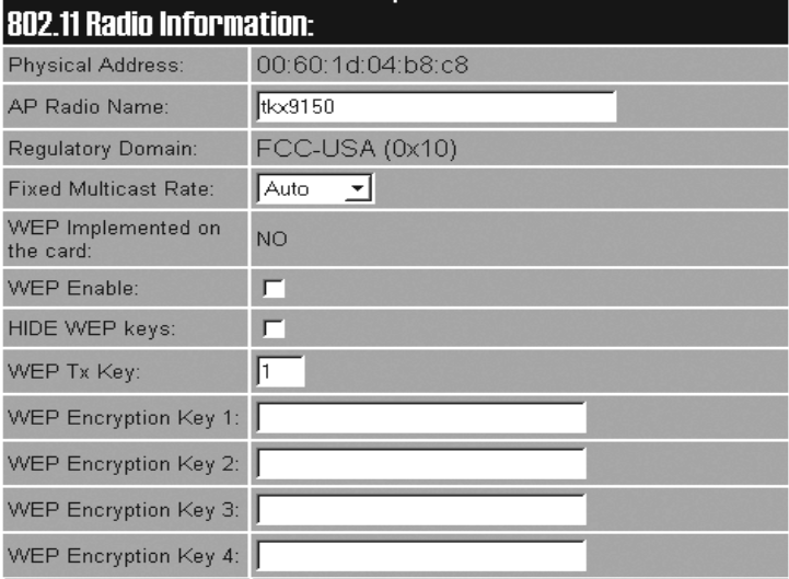
4.2.1.4 802.11 Radio Information
The parameters in this menu set general information about the USI WaveLAN
IEEE 802.11 DSSS PCMCIA card installed in the 9150.
Physical Address
This parameter shows the hardware address (MAC address) of the radio card.
A globally unique MAC address is assigned to each card by the card manufacturer.
The value cannot be changed.
AP Radio Name
To identify each AP, the monitor uses the
radio card's name. The identification can be configured here to give each radio card
a unique name.
The AP Radio Name is an alphanumeric character string of up to 32 characters. The
default value is tkx9150.

Teklogix 9150 Wireless Gateway User Manual 69
Chapter 4: Access Point Configuration
IEEE 802.11 Direct Sequence Radio Parameters Menu
Regulatory Domain
The regulatory domain value identifies the regulatory body’s country code for the
RF regulations with which the radio complies. For the USA, the regulatory body is
the FCC, for Canada it's Industry Canada, and for Europe it's ETSI. The hex value in
brackets beside the name is the code (as specified in the IEEE 802.11b standard) for
that domain. The country codes that are decoded into a name are listed below. For
other country codes the name portion will be replaced with “Unknown”.
Fixed Multicast Rate
This parameter allows you to choose the multicast rate of the installed 802.11, 2.4
GHz TRX7431 radio.
The allowable values for TRX7431 are: Auto, 1, 2, 5.5, or 11Mb/s.
If Auto is chosen, the rate will automatically be set to the radio card’s default
multicast rate.
WEP Implemented on the card
This parameter shows whether the radio card installed on the 9150 supports the
Wired-Equivalent Privacy feature, referred to as WEP. This feature allows you to
encrypt radio traffic to prevent electronic eavesdropping. WEP is available in either
64-bit or 128-bit encryption for the TRX7431 radio. If WEP is not implemented by
the radio card, the WEP parameters are non-functional.
The allowable values are Yes or No, and cannot be changed.
Regulatory Body Domain Code Country
FCC-USA 0x10 USA (for DS radios this is also the code used
for Canada)
Industry Canada 0x20 Canada (currently only for FH radios, this may
change in the future)
ETSI-Europe 0x30 Most of Europe
Spain 0x31 Spain
France 0x32 France
MKK-Japan 0x40 Japan

Chapter 4: Access Point Configuration
IEEE 802.11 Direct Sequence Radio Parameters Menu
70 Teklogix 9150 Wireless Gateway User Manual
WEP Enable
Enabling ( √ ) this parameter makes WEP available for the radio.
The default is disabled.
Hide WEP Keys
This parameter controls access to the WEP keys by replacing the visible key values
with the hidden values “ **** ” when the option is enabled ( √ ). To activate this fea-
ture, the WEP key values must first be entered and then submitted by pressing “OK”
at the bottom of the page. Then, by going back into the IEEE 802.11 Direct
Sequence Radio Parameters menu page (the key values will be visible), enable the
Hide WEP Keys option, and submit the data again. This time you will see that the
key values have been hidden. The feature is now set and remains enabled.
To disable the feature or change any of the WEP key values, you must enter and then
submit ALL of the existing and/or new key values. When you go back to the menu
pages, the key values will be visible again. The default is disabled.
WEP Tx Key
This parameter specifies which WEP Key the 9150 will use when transmitting.
The allowable values are 1 to 4. The default value is 1.
WEP Encryption Key 1 to 4
This parameter allows you to set the encryption key for either 64-bit or 128-bit
encryption. Acceptable values for a key parameter are shown in Table 4.1.
Note: Although the user specifies 40-bit and 104-bit keys, these keys are actually
composed with a 24-bit-long “Initialization Vector” generated inside the
radio card, making up the 64- and 128-bit keys.
Important: The 9150 must be rebooted for changes to these parameters to
take effect.
64-bit Encryption 128-bit Encryption (available with TRX7431 radio only)
5 ASCII characters 13 ASCII characters
“0x”, followed by 10 hex digits “0x”, followed by 26 hex digits
Table 4.1 WEP Encryption Key Values
Teklogix 9150 Wireless Gateway User Manual 71
Chapter 4: Access Point Configuration
IEEE 802.11 Direct Sequence Radio Parameters Menu
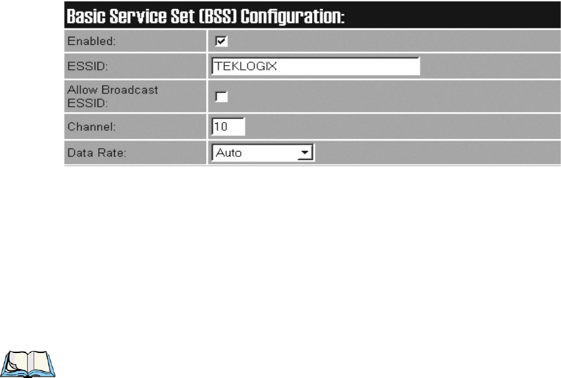
4.2.1.5 Basic Service Set (BSS) Configuration
The 9150 facilitates roaming of terminals across Basic Service Sets (BSS). For a
detailed description, please see “Inter-Access Point Protocol (IAPP)” on page 9.
Enabled
This parameter enables ( √ ) or disables the BSS feature.
ESSID
This is the Extended Service Set Identifier parameter. The ESSID is an alphanumeric
character string of up to 32 characters and is case-sensitive. If your network
includes devices that use the DOS ODI Driver, select alphabetical characters in
uppercase only to allow the DOS ODI devices to connect to the network as well.
Note: The ESSID should be the same for all devices in a system.
Allow Broadcast ESSID
This parameter enables ( √ ) or disables the Broadcast ESSID feature. By default, it
is unchecked and the association of stations that provide an ESSID that is not equal
to this 9150’s ESSID is NOT allowed. This prevents the 9150 from being associated
with any station (802.11 device within radio range) that has its ESSID set to “ANY”
(broadcast SSID).
The default is disabled.
Channel
This parameter sets the operating channel for this radio, as determined by the system
administrator. For a listing of the allowable channels for each country, please see
“PC Card Radios” on page 204.
Chapter 4: Access Point Configuration
IEEE 802.11 Direct Sequence Radio Parameters Menu
72 Teklogix 9150 Wireless Gateway User Manual
Data Rate
The Data Rate parameter allows you to choose whether to fix the data rate (Fixed n)
or set a maximum automatic transmission rate (Auto n) for the BSS channel of the
installed TRX7431 radio. The data rate can also be configured to automatically use
the maximum transmission rate possible for the radio (Auto).
Important: The 9150 must be rebooted for changes to this parameter to
take effect.
The range of values is: Auto, Fixed 1, Fixed 2, Auto 2, Fixed 5.5, Auto 5.5, or
Fixed 11Mb/s.
The default setting is Auto.
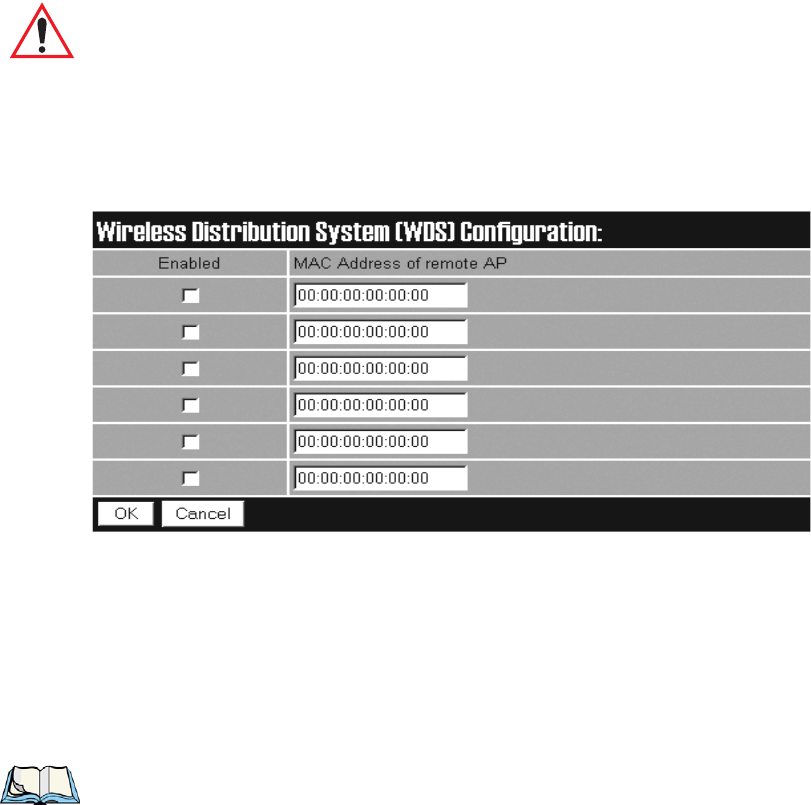
4.2.1.6 Wireless Distribution System (WDS) Configuration
The 9150 Wireless Gateway can be used as an 802.11b wireless access point (AP) to
extend coverage area or for locations difficult to wire; or two 9150s can be used as
an 802.11b bridge connecting two separate wired networks.
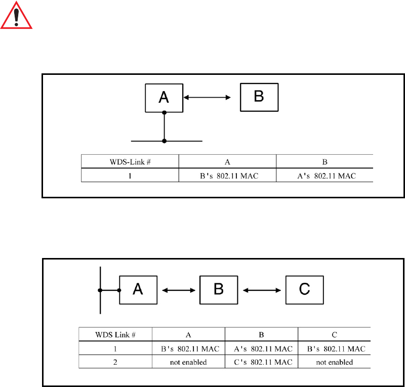
The 9150 access points are linked to each other in the Wireless Distribution System
(WDS). To do this, each of the 9150s in the WDS must be configured to identify the
other access points in the system, using their MAC addresses as described in the fol-
lowing parameter. Examples of various configuration scenarios are provided in
Figure 4.2 on page 73 through Figure 4.5 on page 74.
Note: The Basic Service Set (BSS) operates independently of the WDS. How-
ever, the BSS and WDS share the same bandwidth. For information on
BSS, please refer to “Basic Service Set (BSS) Configuration” on page 71.
Teklogix 9150 Wireless Gateway User Manual 73
Chapter 4: Access Point Configuration
IEEE 802.11 Direct Sequence Radio Parameters Menu
MAC Address Of Remote AP
Each wireless access point linked to this 9150 must be identified by entering its
MAC address here, and the connection must also be enabled ( √ ). Up to six WDS
links can be supported. This 9150’s MAC address must also be configured and
enabled on each of the other access points linked to it in the Wireless Distribution
System.
Important: If there are two radio cards in the wireless 9150 access point, one
radio should be configured for the WDS link, and the other for BSS
coverage. If both radio cards are set for the WDS, one will be auto-
matically disabled.
Figure 4.2 WDS Configurations: One Hop To The Backbone
Figure 4.3 WDS: More Than One Hop To The Backbone
Chapter 4: Access Point Configuration
IEEE 802.11 Direct Sequence Radio Parameters Menu
74 Teklogix 9150 Wireless Gateway User Manual
Figure 4.4 WDS: Multiple APs Connected To One AP In The Backbone
Figure 4.5 WDS: Multiple APs Connected To Another Wireless AP
Teklogix 9150 Wireless Gateway User Manual 75
Chapter 4: Access Point Configuration
Access Point Configuration Menu Options
4.3 Access Point Configuration Menu Options
The Access Point Configuration main menu consists of three sub-menus:
MAC Bridge Parameters, Mobility Configuration, and Mobile IP Parameters.
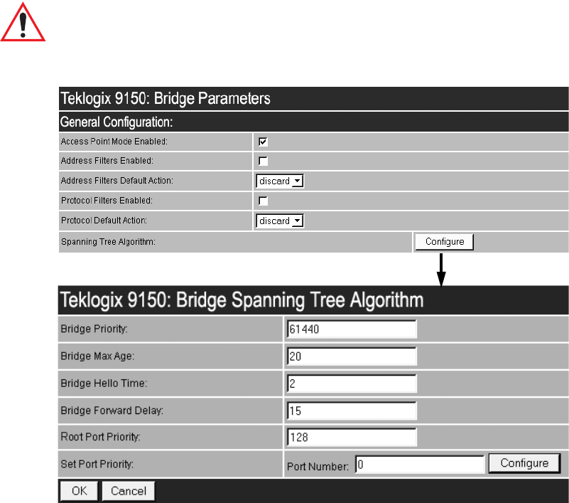
4.4 MAC Bridge Parameters
The MAC Bridge parameters consist of protocol filters that direct the 9150 to
forward or discard frames that contain a known protocol type. This enables the 9150
to be selective of what types of frames will be bridged over the radio, in order to
limit traffic on busy networks. Filtering frames is based on the protocol information
in the frame. This is discussed in detail in “Protocol Filters” on page 83.
The MAC Bridge Parameters page is entered from the Access Point Configuration
menu on the first page, as shown above.
Figure 4.6 on page 76 charts the pages for the MAC bridge filters. Entering “OK” or
“Cancel” in the individual Filter pages will return you to the Bridge Parameters page.
Chapter 4: Access Point Configuration
MAC Bridge Parameters
76 Teklogix 9150 Wireless Gateway User Manual
Figure 4.6 Overview Of MAC Bridge Configuration Menus
Teklogix 9150 Wireless Gateway User Manual 77
Chapter 4: Access Point Configuration
General Configuration
4.4.1 General Configuration
Access Point Mode Enabled
When this 9150 is used only as an 802.IQ base station and not as an access point,
this parameter should be disabled to reduce CPU time. Only broadcast and
multicast frames will be passed through. Enable ( √ ) this parameter for the 9150
functioning as an access point.
The default value is enabled.
Address Filters Enabled
The checkbox in this parameter enables or disables the Address Filters function. If
filtering is enabled ( √ ), the 9150 can filter out frames based on destination MAC
addresses. The list of MAC addresses for filtering is set by the Address Filters option
on page 81. Frames are filtered and either forwarded or discarded, depending on the
rest of the settings in this configuration. If filtering is disabled, no filtering will be
done based on MAC addresses.
Address Filters Default Action
This parameter determines which Address Filters Default Action (discard or for-
ward) will be performed when the Address Filters Enabled parameter is checked
(√). If an address does not match any of the addresses set in the Address Filters con-
figuration (see page 81), then it will take the Address Filters Default Action selected
in this parameter.

Chapter 4: Access Point Configuration
General Configuration
78 Teklogix 9150 Wireless Gateway User Manual
For example, the Address Filters Default Action may be to discard all frames des-
tined for addresses not matched in the configuration database. Therefore if the
address type field is not matched, the frame will be discarded. But if an address type
field is matched in the database, the frame will be forwarded for that address.
Conversely, if the default action is to forward all frames destined for addresses
not matched in the configuration database, those frames will be passed on for
those addresses, but frames for an address type field matched in the database will
be discarded.
Protocol Filters Enabled
The checkbox in this parameter enables or disables the Protocol Filters function. If
filtering is enabled ( √ ), frames are filtered and either forwarded or discarded,
depending on the rest of the settings in this configuration. If filtering is disabled, no
filtering will be done based on protocol frames.
Protocol Default Action
This parameter determines which Protocol Default Action (discard or forward) will
be performed when the Protocol Filters Enabled parameter is checked (√). Each
Protocol Filter (see page 83) also has a forward/discard action associated with it. If a
frame does not match any of the filters set in the Protocol Filters configuration, then
it will take the Protocol Default Action selected in this parameter.
For example, the Protocol Default Action may be to discard all frames. If a type
field is matched in the configuration database, and the Filters action is forward, the
frame will be passed on. If the field is not matched, then the frame will be dis-
carded. Therefore if you want only IP frames forwarded, after selecting the appro-
priate IP Type in the Ethernet II Filters (see page 86) the discard setting here will
drop all frames containing other protocol types.
Important: If Protocol Filters Enabled is checked, and the Protocol Default
Action is discard, an HTTP browser will not be able to access the
9150’s configuration pages unless an ARP filter is defined to
forward ARP packets. To do this, configure Ethernet II Filters to
forward protocol type 0x0806 (ARP) packets (see page 86). Alterna-
tively, you can create a static entry in the ARP table on the compu-
ter that is running the browser.
Teklogix 9150 Wireless Gateway User Manual 79
Chapter 4: Access Point Configuration
General Configuration
4.4.1.1 Bridge Spanning Tree Algorithm
The Spanning Tree Algorithm and its Bridge Protocol work to support and maintain
MAC Bridge performance.
Important: These parameters are set with optimum default values. Do not
adjust these values without discussing the effects with your Psion
Teklogix representative.
Bridge Priority
This parameter helps a network manager select the active topology of the Bridged
Local Area Network by influencing the selection of the Root Bridge. The 2-octet
value is appended as the most significant portion of a bridge ID. A lower numerical
value for the bridge priority makes the bridge more likely to become the root.
The default value is 61440 (which equals 0xF000 in hexadecimal notation).
Chapter 4: Access Point Configuration
General Configuration
80 Teklogix 9150 Wireless Gateway User Manual
Bridge Max Age
The value of the Maximum Age parameter sent in a Configuration BPDU (Bridge
Protocol Data Unit) when the 9150 is the Root or is attempting to become the Root.
The Maximum Age is the message age at which a received configuration message is
judged “too old” and is discarded. If the selected value is too small, then occasion-
ally the spanning tree will configure unnecessarily, possibly causing temporary loss
of connectivity in the network. If the selected value is too large, the network will
take longer than necessary to adjust to a new spanning tree after a topological event
such as the restarting or crashing of a bridge or link. A conservative value is to
assume a delay variance of 2 seconds per hop. The value recommended by IEEE
802.1d is 20 seconds.
The default value is 20.
Bridge Hello Time
The time interval between the transmission of Configuration BPDUs by a 9150 that
is the Root or is attempting to become the Root.
The recommended time is 2 seconds. Shortening the time will make the protocol
more robust, in case the probability of loss of configuration messages is high.
Lengthening the time lowers the overhead of the algorithm (because the interval
between transmission of configuration messages will be larger).
The default value is 2.
Bridge Forward Delay
The value of the Forward Delay parameter sent in a Configuration BPDU when the
9150 is the Root or is attempting to become the Root.
The Forward Delay temporarily prevents a bridge from starting to forward data
packets to and from a link until news of a topology change has spread to all parts of
a bridged network. This should give all links that need to be turned OFF in the new
topology time to do so before new links are turned ON.
The default value is 15.
Teklogix 9150 Wireless Gateway User Manual 81
Chapter 4: Access Point Configuration
Address Filters: MAC Address
Root Port Priority
The Root Port Priority parameter sets the initial priority value assumed by the Root
Port. The default value is 128.
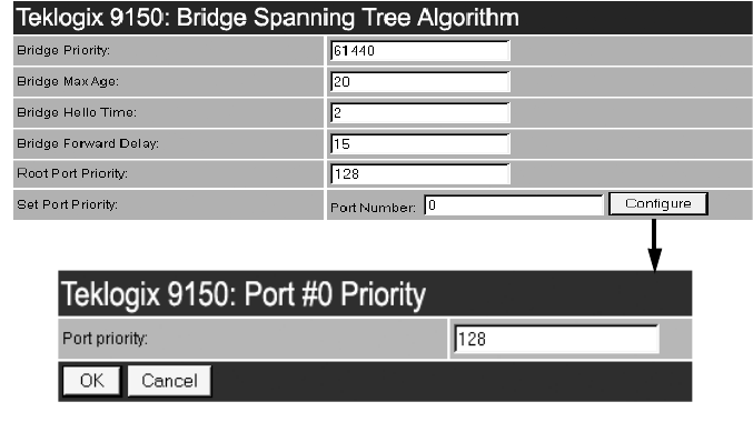
Set Port Priority
The Set Port Priority parameter sets the prioritization of each enabled port. A lower
numerical value for the port priority makes the port more likely to become the desig-
nated port. Port Number 1 corresponds to the wired interface; Port Numbers 2 to
7 correspond to WDSLinks 1 to 6. To set the priority, enter the port number in the
textbox and then press the “Configure” button. Then enter the priority number for
that port in the textbox.
Valid values range from 0 to 255. The default value is 128.
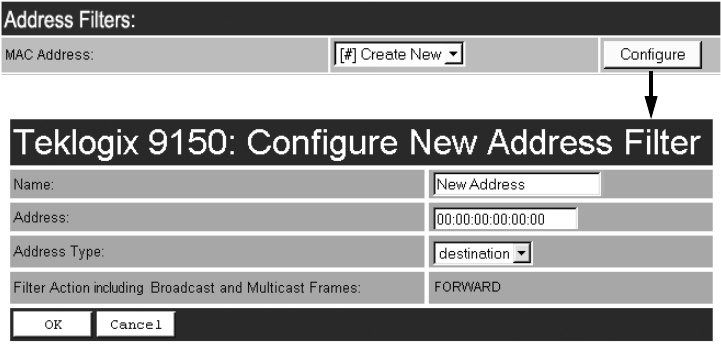
4.4.2 Address Filters: MAC Address
The 9150 can use a list of destination MAC addresses to filter out frames. The MAC
addresses are those of any terminals associating with the 9150. If Address Filters
Enabled on page 77 is checked ( √ ) and Address Filters Default Action (page 77) is
set to discard, then any frame destined for any address in the list will be forwarded.
If Address Filters Default Action is set to forward, then those frames will be dis-
carded. Addresses are added to the filter list by entering the “Configure” dialogue
box from the Bridge Parameters menu.
Chapter 4: Access Point Configuration
Address Filters: MAC Address
82 Teklogix 9150 Wireless Gateway User Manual
Name
This is any name you wish to use to describe this terminal.
Address
This parameter provides the corresponding MAC address for the terminal.
Address Type
This parameter defines whether the source or destination address of the frame
should be used to determine the filter action. The destination address has priority
over the sources address. Therefore, when a frame is filtered, if its destination
address is set for discarding but its source address is set for forwarding, the frame
will be discarded.
The default setting is destination.
Filter Action Including Broadcast And Multicast Frames
This parameter shows the filter action set in the “Address Filters Default Action” on
page 77, which either forwards or discards frames based on the MAC address con-
figured here. If the action is shown as “Forward”, the frames for this address will be
discarded. If the action is “Discard”, the frames will be forwarded. The parameter is
not configurable in this menu.
Teklogix 9150 Wireless Gateway User Manual 83
Chapter 4: Access Point Configuration
Protocol Filters
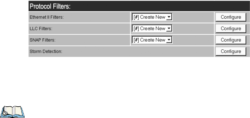
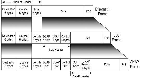
4.4.3 Protocol Filters
When the 9150 receives frames, it can forward or discard the messages by filtering
the protocol Type fields encapsulated in the frame. The filtering is done on three
types of Ethernet headers: Ethernet II, LLC and SNAP.
Figure 4.7 on page 84 illustrates the Ethernet header formats. The parameters to
configure these filters are described in the sections which follow.
Note: Throughout these menus, the values for all the protocol types are, by con-
vention, entered in hexadecimal, preceded by “0x”.
The fields for a basic IEEE 802.3 Ethernet frame consist of a six-byte destination
MAC address, followed by a six-byte source MAC address, and a two-byte protocol
Type. The final fields in a frame are the Data field and the FCS field (Frame Check
Sequence, or CRC). If the Type field contains a value that is greater than or equal to
“0x0600”, it is assumed to be the protocol identifier for an Ethernet II header. This
field is used to determine which protocol is being used in the frame, and this is what
can be filtered (see “Ethernet II Filters” on page 86).
If the protocol Type is less than “0x05DC”, then the value is interpreted as a Length
field instead. It is assumed that an IEEE 802.2 Logical Link Control (LLC) header is
to follow the Length. This header consists of the Destination Service/Source Service
Access Point (DSAP/SSAP) and Control fields (see “LLC Filters” on page 87).
Chapter 4: Access Point Configuration
Protocol Filters
84 Teklogix 9150 Wireless Gateway User Manual
If the DSAP and SSAP are both “0xAA”, and the Control field has a value of
“0x03”, the LLC header will be followed by an extension which is a SNAP header.
The SNAP header includes the Organizational Unit Identifier (OUI) and the
protocol type (see “SNAP Filters” on page 88).
Figure 4.7 Ethernet Frame Types
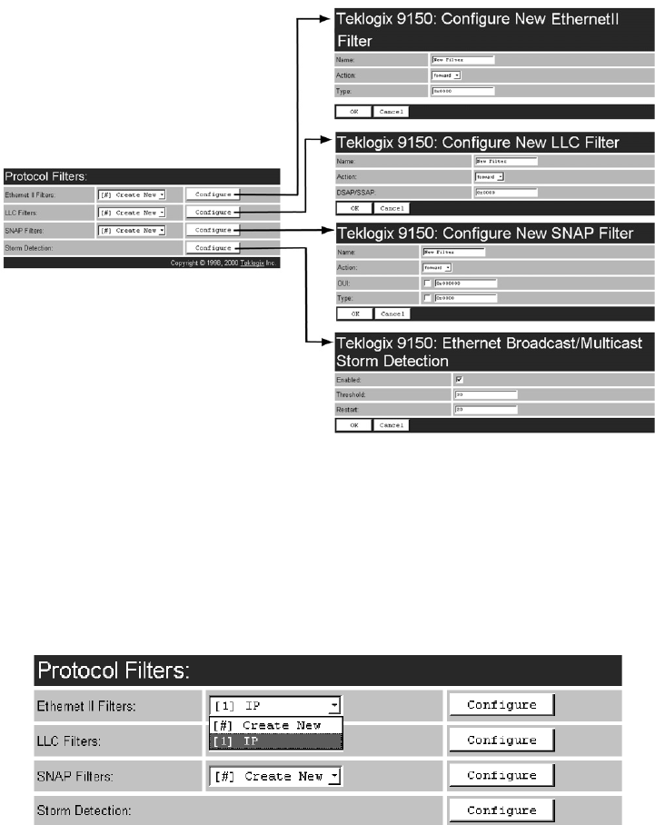
The listboxes in the Protocol Filters option show the protocol filters already set in
the configuration database. Selecting a protocol name and then opening the “Config-
ure” dialog box gives a list of parameter settings that can be modified or deleted for
that protocol.
Teklogix 9150 Wireless Gateway User Manual 85
Chapter 4: Access Point Configuration
Protocol Filters
Figure 4.8 Protocol Filters Main Menu And Sub-menus
New filters can be added by selecting “[#] Create New” in the listbox before enter-
ing the “Configure” dialog box. Once a filter is created, the option to delete it can be
found on its configuration page (for example, see “Ethernet II Filters” on page 86).
When choosing to delete a filter, you will be prompted for confirmation of the dele-
tion, which will give you the opportunity to cancel the action.
Chapter 4: Access Point Configuration
Protocol Filters
86 Teklogix 9150 Wireless Gateway User Manual
If a hexadecimal number is entered that is outside the minimum or maximum allow-
able value for these parameters, you will receive an alert that the Type value is
invalid for the specified protocol.
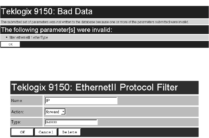
4.4.3.1 Ethernet II Filters
Name
This is any name you wish to use to describe this Ethernet II filter.
Action
This parameter can be set to either forward or discard frames with protocol types
that match this filter.
Type
The value entered in this parameter must be a four-digit hexadecimal number
ranging from 0x0600 to 0xFFFF, which represents the Ethernet II protocol type you
wish to filter. For example, if you only use TCP/IP, create two protocol filters, one to
forward IP (Type 0x0800) and the other to forward ARP (Type 0x0806). For a
listing of Ethernet II types, see “Ethernet II Types (RFC 1700)” on page C-1.
Teklogix 9150 Wireless Gateway User Manual 87
Chapter 4: Access Point Configuration
Protocol Filters
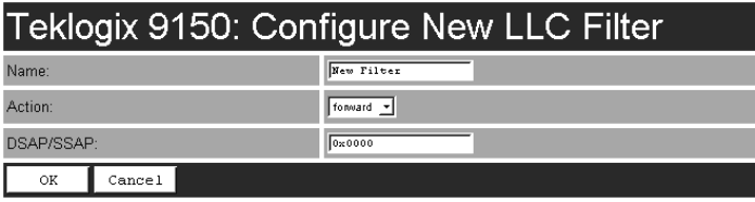
4.4.3.2 LLC Filters
Name
This is any name you wish to use to describe this LLC filter.
Action
This parameter can be set to either forward or discard frames with protocol types
that match this filter.
DSAP/SSAP
The value entered in the Destination Service/Source Service Access Point
(DSAP/SSAP) parameter must be a four-digit hexadecimal number ranging from 0
to 0xFFFF, where the first pair of digits is the DSAP and the last pair is the SSAP.
For a listing of DSAP/SSAP types, see “DSAP/SSAP Types” on page C-14.
Chapter 4: Access Point Configuration
Protocol Filters
88 Teklogix 9150 Wireless Gateway User Manual
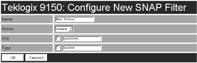
4.4.3.3 SNAP Filters
Name
This is any name you wish to use to describe this SNAP (SubNet Access Protocol)
filter.
Action
This parameter can be set to either forward or discard frames with protocol types
that match this filter.
OUI
The value entered in this parameter must be a six-digit hexadecimal number ranging
from 0 to 0xFFFFFF, which is the Organization Unique Identifier. When this
parameter is enabled ( √ ), the OUI will be filtered.
Type
The value entered in this parameter must be a four-digit hexadecimal number
ranging from 0 to 0xFFFF, which represents the SNAP type you wish to filter.
When this parameter is enabled ( √ ), this Type will be filtered.
For a short listing of OUI values, see “OUI Values” on page C-15.
Teklogix 9150 Wireless Gateway User Manual 89
Chapter 4: Access Point Configuration
Protocol Filters
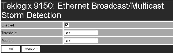
4.4.3.4 Storm Detection
This filter parameter can prevent broadcast/multicast storms from spreading
throughout the network. Network storms can burden radio traffic with unnecessary
data transmissions.
Enabled
This parameter enables ( √ ) or disables the Storm Detection filters.
Threshold
The maximum number of broadcast/multicast frames that should be received in one
second is defined in this parameter. When that threshold is exceeded, a broadcast
storm is declared. Every broadcast/multicast frame received will be discarded until it
is determined that the storm is over (see Restart, below). Setting the value for
Threshold is determined by the characteristics of your network.
The default value is 200.
Restart
The broadcast storm is determined to be over when the number of broadcast frames
received for a one second period is less than or equal to the value entered in this
parameter. Setting the value for Restart is determined by the characteristics of
your network.
The default value is 150.
Chapter 4: Access Point Configuration
Mobility Configuration
90 Teklogix 9150 Wireless Gateway User Manual
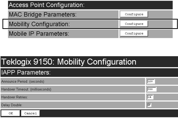
4.5 Mobility Configuration
The Mobility Configuration page is entered from the Access Point Configuration
menu on the first page.
Going to the Mobility Configuration page opens the IAPP Parameters options.
The Inter-Access Point Protocol (IAPP) is an extension to the IEEE 802.11b
protocol. In a multiple-9150 system, IAPP facilitates roaming of mobile stations
(terminals) among the 9150s, and enables communication and awareness between
the 9150s.
Every terminal is associated with one 9150, but it can re-associate with another 9150
to maintain uninterrupted communications. The association is “handed over” from
one 9150 to the next. The newly-associated 9150 will receive the terminal’s data
frames and pass them onto the LAN. Returning frames are no longer accepted by the
original 9150, which has disassociated from that terminal. Returning frames are now
accepted by the newly-associated 9150 and passed over the RF to the terminal.
To implement these procedures and coordinate the 9150s, IAPP specifies two
message types: Announce and Handover.

Teklogix 9150 Wireless Gateway User Manual 91
Chapter 4: Access Point Configuration
IAPP Parameters
In IAPP Announce procedures, when the 9150 is initialized, it sends an IP multicast
message to inform the other 9150s in the network that it has become active. It also
informs the other 9150s of its continued operation (‘alive’ status) by periodically
multicasting the Announce beacon.
The Handover protocol is intended to inform the old 9150 that a terminal has been
associated with a new 9150, and to update the filter tables of intermediate MAC-
bridges to correctly forward frames destined for the terminal. The newly-associated
9150 sends a Handover request to the old 9150, which disassociates itself and
acknowledges the request.
Important: These parameters are set with optimum default values. Do not
adjust these values without discussing the effects with your Psion
Teklogix representative.
4.5.1 IAPP Parameters
Announce Period
The Announce Period parameter indicates the number of seconds between
Announce broadcasts. For further information, see “Mobility Configuration” on
page 90.
Handover Timeout
If there is no response to the Handover request by the 9150 within the time specified
in the Handover Timeout parameter, the request is retransmitted. If no response is
received after a number of retries (set in the Handover Retries parameter, below),
the 9150 will complete the reassociation procedure itself. For further information,
see “Mobility Configuration” on page 90.
Handover Retries
This parameter sets the number of times the 9150 will transmit a Handover request
to the disassociated 9150, before it completes the association transfer itself. See also
Handover Timeout, above.
Delay Double
The Delay Double parameter doubles the amount of Handover Timeout between
Handover Retries. For example, if the first retry is after 500 milliseconds, the next
Handover request is sent after 1 second, followed by a retry after 2 seconds, etc.
Chapter 4: Access Point Configuration
Mobile IP Parameters
92 Teklogix 9150 Wireless Gateway User Manual
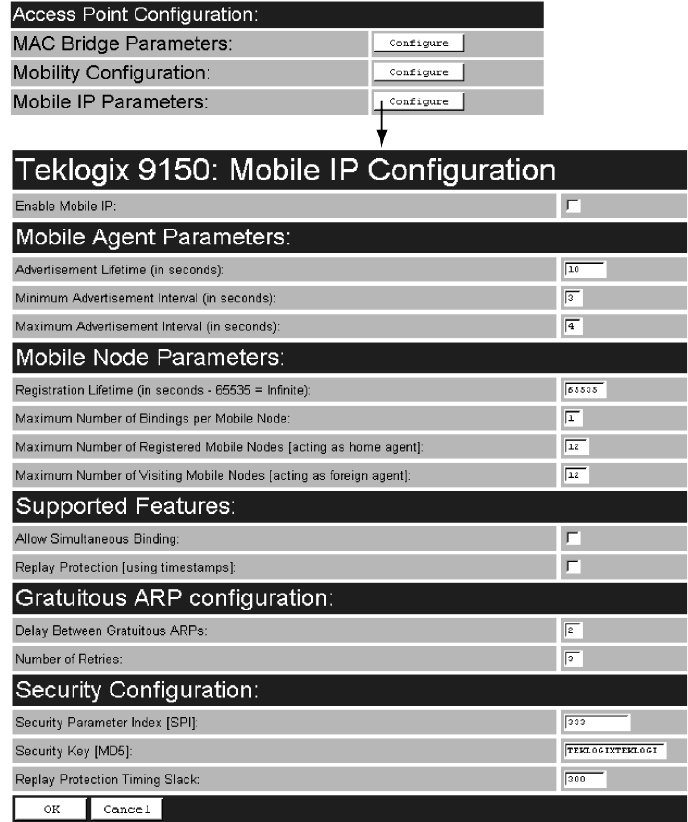
4.6 Mobile IP Parameters
Mobile IP is used to allow mobile nodes (i.e. terminals) to roam seamlessly between
different TCP/IP subnets (10.16.xxx.xxx -> 10.128.xxx.xxx), through foreign and
home “agents” (9150s), which act as proxies. When the terminal roams away from
its home network, the home agent will take all packets destined for the mobile node,
and send them on to the foreign agent, which relays the packets to the “node” (terminal).
Teklogix 9150 Wireless Gateway User Manual 93
Chapter 4: Access Point Configuration
Mobile IP Configuration
4.6.1 Mobile IP Configuration
Enable Mobile IP
This parameter enables ( √ ) or disables the Mobile IP feature.
The default is disabled.
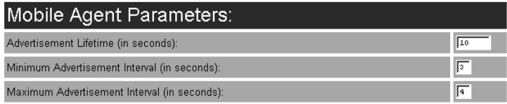
4.6.1.1 Mobile Agent Parameters
Advertisement Lifetime
This parameter is the maximum length of time (in seconds) that the advertisement is
considered valid in the absence of further advertisements. If the mobile node does
not get an advertisement within this period of time, it will assume it has lost contact
with that agent. It will then attempt to register any other agent that it has heard.
The acceptable value ranges from 3 to 30. The default value is 10.
Minimum Advertisement Interval
This parameter is the minimum period of time (in seconds) between advertisements.
The nominal interval at which the agent advertisements are sent should be 1/3 of the
Advertisement Lifetime parameter value. This allows the mobile node to miss three
successive advertisements before deleting the agent from its list of valid agents.
The acceptable value ranges from 1 to 10. The default value is 3.
Maximum Advertisement Interval
This parameter is the maximum period of time (in seconds) between advertisements.
The nominal interval at which the agent advertisements are sent should be 1/3 of the
Advertisement Lifetime parameter value. This allows the mobile node to miss three
successive advertisements before deleting the agent from its list of valid agents.
The acceptable value ranges from 1 to 10. The default value is 4.
Chapter 4: Access Point Configuration
Mobile IP Configuration
94 Teklogix 9150 Wireless Gateway User Manual
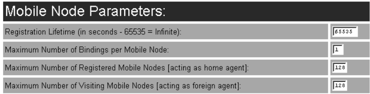
4.6.1.2 Mobile Node Parameters
Registration Lifetime
This parameter is the maximum registration lifetime that a terminal will register for,
in seconds. This value depends on the dynamics of your system. A few tenths of
seconds to a few minutes seem appropriate. The value 65535 is equivalent to
“infinite” for the parameter using it. If the terminal requests a value that is larger
than the value configured in the Home Agent, the registration will be rejected and
the terminal will have to retry with a lower value.
The acceptable value ranges from 300 to 65535. The default value is 65535.
Maximum Number Of Bindings Per Mobile Node
This parameter represents the maximum number of simultaneously available
agents for each mobile node. It should be set to a reasonable value, according to the
maximum number of base stations that can be in the mobile node's range simulta-
neously. Some margin should be taken since although being short on the number of
agents will not prevent the system from working, it is not ideal.
The acceptable value ranges from 1 to 5. The default value is 1.
Maximum Number Of Registered Mobile Nodes
This parameter is the maximum number of terminals that can register with this 9150
acting as a home agent.
The acceptable value ranges from 1 to 255. The default value is 128.
Maximum Number Of Visiting Mobile Nodes
This parameter is the maximum number of terminals that can communicate to the
home agent via this 9150 acting as a foreign agent.
The acceptable value ranges from 1 to 255. The default value is 128.
Teklogix 9150 Wireless Gateway User Manual 95
Chapter 4: Access Point Configuration
Mobile IP Configuration
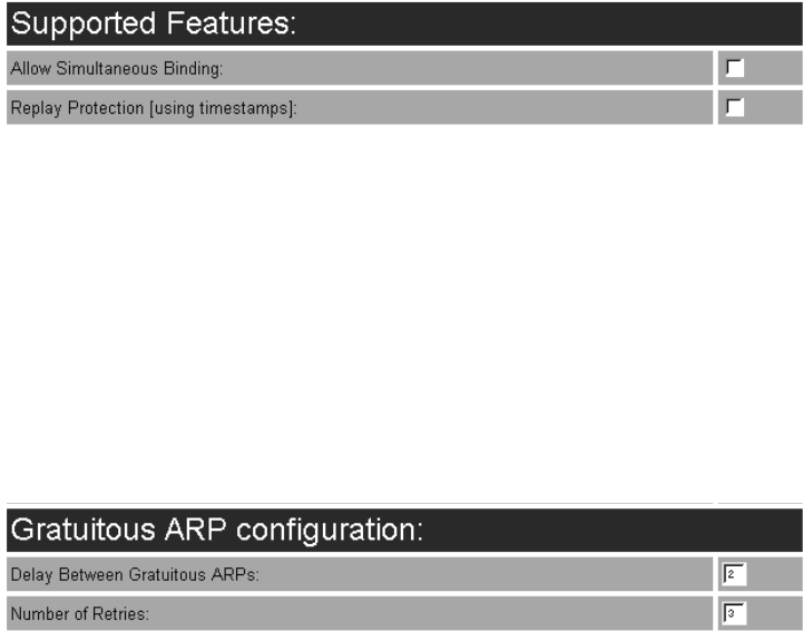
4.6.1.3 Supported Features
Allow Simultaneous Binding
This parameter enables ( √ ) multiple (simultaneous) bindings.
The default value is disabled.
Replay Protection
This parameter enables ( √ ) time-stamp based replay protection. The mobile node
and home agent values for this parameter must match.
The default value is disabled.
4.6.1.4 Gratuitous ARP Configuration
Delay Between Gratuitous ARPs
This parameter is the delay (in seconds) between gratuitous ARP retransmission.
The acceptable value ranges from 1 to 5. The default value is 2.
Number of Retries
This parameter is the maximum number of sent gratuitous ARPs on the home net-
work, when the home agent accepts a registration from a mobile node.
The acceptable value ranges from 1 to 5. The default value is 3.
Chapter 4: Access Point Configuration
Mobile IP Configuration
96 Teklogix 9150 Wireless Gateway User Manual
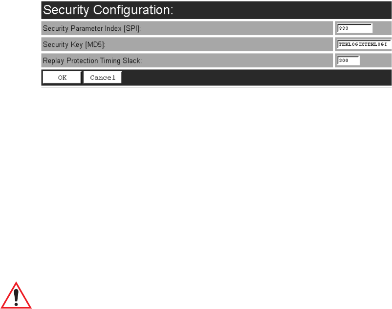
4.6.1.5 Security Configuration
Security Parameter Index (SPI)
This parameter is the Security Parameter Index (SPI) of association with the home
agent. The SPI value must match the SPI value on the mobile node.
The minimum acceptable value is 256. The default value is 333.
Security Key (MD5)
The Security Key parameter is in ASCII text with a maximum length of 16 bytes.
The agent key must also match the key on the mobile node.
The default value is TEKLOGIXTEKLOGIX.
Replay Protection Timing Slack
This parameter provides Timestamp-based replay protection.
Important: In order for this parameter to operate, SNTP must also be enabled
(see “SNTP” on page 47).

Teklogix 9150 Wireless Gateway User Manual 97
BASE STATION CONFIGURATION 5
5.1 Overview................................99
5.2 General Configuration Menu: Interfaces. . ............. 102
5.2.1 TekLAN Parameters . . . . . . . . . . . . . . . . . . . 102
5.2.1.1 Radio........................103
5.2.1.2 Wireless LAN Parameters . . . . . . . . . . . . . 105
5.2.2 Narrow Band Radio Parameters . . . . . . . . . . . . . 106
5.2.2.1 General Options . . . . . . . . . . . . . . . . . . 108
5.2.2.2 TRX7370 Radio Card Parameters . . . . . . . . . 108
5.2.2.3 Connectivity Options: Base Station Mode . . . . 112
5.2.2.4 Connectivity Options: RRM Mode . . . . . . . . 117
5.3 Base Station Configuration Menu Options .............118
5.3.1 Base Stations.......................118
5.3.2 RRM Groups.......................120
5.3.2.1 Configure New RRM Group. . . . . . . . . . . . 120
5.3.2.2 RRM Group Menu. . . . . . . . . . . . . . . . . 126
5.3.3 Radio Link Features...................128
5.4 Hosts Menu .............................131
5.5 Host Menu Options ......................... 134
5.5.1 9010 / TCP/IP . . . . . . . . . . . . . . . . . . . . . . 135
5.5.1.1 General Host Options . . . . . . . . . . . . . . . 135
5.5.1.2 Emulation Options. . . . . . . . . . . . . . . . . 136
5.5.1.3 Protocol Options. . . . . . . . . . . . . . . . . . 137
5.5.1.4 Function Key Mappings . . . . . . . . . . . . . . 137
Teklogix 9150 Wireless Gateway User Manual 99
Chapter 5: Base Station Configuration
Overview
5.1 Overview
The 9150 Wireless Gateway can function as either a wired or wireless Base Station,
or as a Remote Radio Module (RRM), using a radio link and Psion Teklogix propri-
etary protocols to facilitate communications with the terminals (see also “Radio Pro-
tocols” on page 7).
As a wired base station, the 9150 can communicate with both wireless base stations
and terminals using either Adaptive Polling/Contention or Wlan Protocols (see page
11), and is connected to the network controller over a network.
As a wireless base station, the 9150 communicates with the wired base station and
mobile terminals using the Wlan Protocol.
As an RRM, the operation and timing of the 9150’s radio link to the terminals is
directly controlled by a network controller that uses a timeplexing radio protocol
(see “Timeplexing And Cellular Switching”, below). It is connected to the network
controller over a network.
Timeplexing And Cellular Switching
There are two methods of operating on the radio link. The first method is called
cellular switching. It is similar in concept to cellular telephone systems. Here,
each base station uses a different radio channel. The terminals monitor the radio link
and automatically switch to the channel with best radio reception. This cellular
switching capability is transparent to the host.
The second method is called timeplexing. Here, all Remote Radio Module (RRM)
bases at the site use the same channel. Over a UDP/IP network, a network controller,
or the 9150 as a mini-controller, coordinates the polling sequence so that the RRMs
do not transmit simultaneously. This timeplexing capability is also transparent to the
host. Timeplexing is suited for sites with low transaction rates.
Cellular switching and timeplexing can be combined within one Teklogix system:
a site may operate on two or more channels, with several grouped timeplexed bases
using each channel, and cellular switching between the channels.
In all of these cases, the operator may move freely throughout the site without loss
of communication. The Teklogix system handles channel-switching and handovers
between bases without alerting the user.
Chapter 5: Base Station Configuration
Overview
100 Teklogix 9150 Wireless Gateway User Manual
Figure 5.1 9150 Base Station/RRM Configuration
For operation as a base station or RRM, the parameters in the Base Station Configu-
ration pages on the Configuration Main Menu screen should be set appropriately, as
described in the sections that follow. In addition, the appropriate radio and host
parameters must be applied. The radio parameters are found in the Interfaces pages
for TekLAN and Narrow Band radios. See pages 102 and 106, respectively. The host
parameters are found in the Mini-Controller Configuration: Hosts pages, which can
be found starting on page 131. See Figure 5.2 on page 101 for an overview of the
menus involved.
Note: The 9150 main parameters should first be set up as described in Chapter 3:
“9150 Main Configuration”. For details on the RF protocols, see page 11.
ETHERNET
TCP/IP
9150 Wireless Gateway
9400 Network Controller
9150
Wireless Gateway
Host
Teklogix 9150 Wireless Gateway User Manual 101
Chapter 5: Base Station Configuration
Overview
Figure 5.2 Overview Of Menus For Base Station Configuration
Chapter 5: Base Station Configuration
General Configuration Menu: Interfaces
102 Teklogix 9150 Wireless Gateway User Manual
5.2 General Configuration Menu: Interfaces
5.2.1 TekLAN Parameters
The pull-down menu shown for the Interfaces option in the 9150 Configuration
Main Menu page indicates which interfaces have been detected in use. Entering the
“Configure” dialog box for “Slot A: TekLAN Card”, opens the parameters page for
TekLAN, which presents both the radio and Wlan parameters.
Figure 5.3 Overview Of TekLAN Menus
Teklogix 9150 Wireless Gateway User Manual 103
Chapter 5: Base Station Configuration
TekLAN Parameters
5.2.1.1 Radio
Radio Type
The type of PC radio card installed on the 9150 is dependent on your wireless net-
work. This parameter should be set to the installed radio. The TekLAN radio is the
TekLAN 902 MHz DS Spread Spectrum.
Important: If changing radio types in the 9150, DO NOT “hot swap” the PC
cards: turn the 9150 off before changing the radio. Following this,
when changing the Radio Type parameter, the unit must be
powered OFF and ON again (“cold” rebooted). Rebooting with the
Reboot Unit option will not implement the radio parameter change.
Data Rate
This parameter determines the data (baud) rate for the radio channel. This is a
decimal value in bits per second. The acceptable value for the Data Rate parameter
for the TekLAN 902 MHz DS SS is 122kb/s.
Chapter 5: Base Station Configuration
TekLAN Parameters
104 Teklogix 9150 Wireless Gateway User Manual
Channel n Enabled
These parameters are used to enable ( √ ) or disable a channel. The number of chan-
nels available is determined by the type of radio installed. See “PC Card Radios” on
page 204 for the number of available channels for each radio type.
Active Channel
This parameter determines the current default radio channel.
Range
The federal agencies, Industry Canada and the Federal Communications Commis-
sion in the United States, as well as other country-specific agencies world-wide,
regulate the use of radio frequencies to ensure that communication conflicts are
avoided. See “PC Card Radios” on page 204 for the assigned frequencies for each
radio type.
The Range parameter determines which channels can be enabled and is set accord-
ing to the approved frequency range in the country where the system is installed.
The TekLAN 902 MHz radio is only assigned the 902 MHz frequency.
Enable Card
This parameter enables the PC card ( √ ). The card may be disabled temporarily
when, for testing purposes, it is required that there be no radio interference.
Auto-Startup
This parameter enables ( √ ) polling immediately when the 9150 is rebooted. If
Auto-Startup is disabled, the 9150 will wait until polling is initialized from the
network controller. When the 9150 is operating as a Wlan base station under a
network controller, this parameter should be disabled.
Teklogix 9150 Wireless Gateway User Manual 105
Chapter 5: Base Station Configuration
TekLAN Parameters
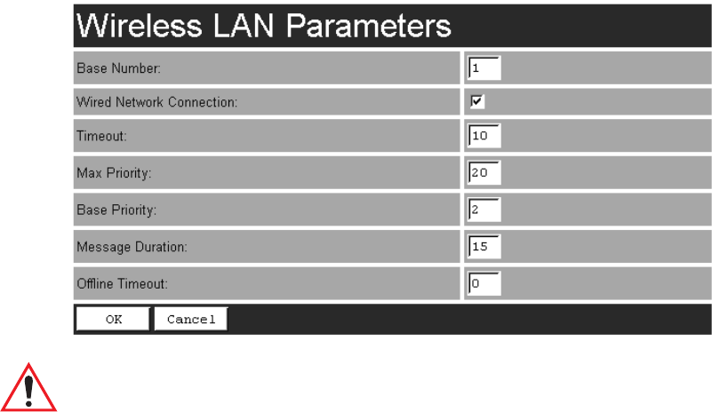
5.2.1.2 Wireless LAN Parameters
The Wlan protocol can only be used with spread spectrum radios.
Important: If your system is using the Wlan protocol, make sure that Operate
in Cellular Mode is enabled (see page 128) in the Radio Link Fea-
tures sub-menu and that cellular mode is also set on the 9400/
Network Controller.
Base Number
This parameter is used to assign a unique address to each base station. As the termi-
nals move from one base station to another, this address is transmitted by the base
stations to the terminals, identifying each 9150 on a multiple base station system.
The allowable range of base station numbers is 1 to 64.
Wired Network Connection
This parameter should be enabled ( √ ) if the 9150 is directly connected (wired) to
the network. If the 9150 is a wireless base station, this parameter should be disabled.
The default setting is enabled.
Timeout
This value is used to adjust Wlan performance and should be set to 10.
Chapter 5: Base Station Configuration
Narrow Band Radio Parameters
106 Teklogix 9150 Wireless Gateway User Manual
Max Priority
This value is used to adjust Wlan performance and should be set to 20.
Base Priority
The Base Priority parameter determines the number of priority transmit slots
reserved for each base station. The allowable range for this parameter is 0 to 100.
For optimal performance, this parameter should be set to a value of 2.
Message Duration
This parameter controls the duration of transmit slots to optimize communications
and decrease the likelihood of collisions. A Message Duration value of 1
translates into a slot duration of 130 micro seconds. The allowable range for this
parameter is 2 to 200. For optimal performance, this parameter should be set to 15.
Offline Timeout
This parameter determines the time in minutes that a terminal is allowed to be inac-
tive before the 9150 declares it offline. An offline terminal is still considered part of
the system. Messages to offline terminals are queued at the 9150. The terminal
remains offline until it transmits any message. Values for this parameter range from
0 to 100. If the parameter is set to 0, terminals are never declared offline.
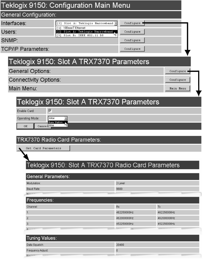
5.2.2 Narrow Band Radio Parameters
The pull-down menu shown for the Interfaces option on the 9150 Configuration
Main Menu page indicates which interfaces have been detected in use. For the selec-
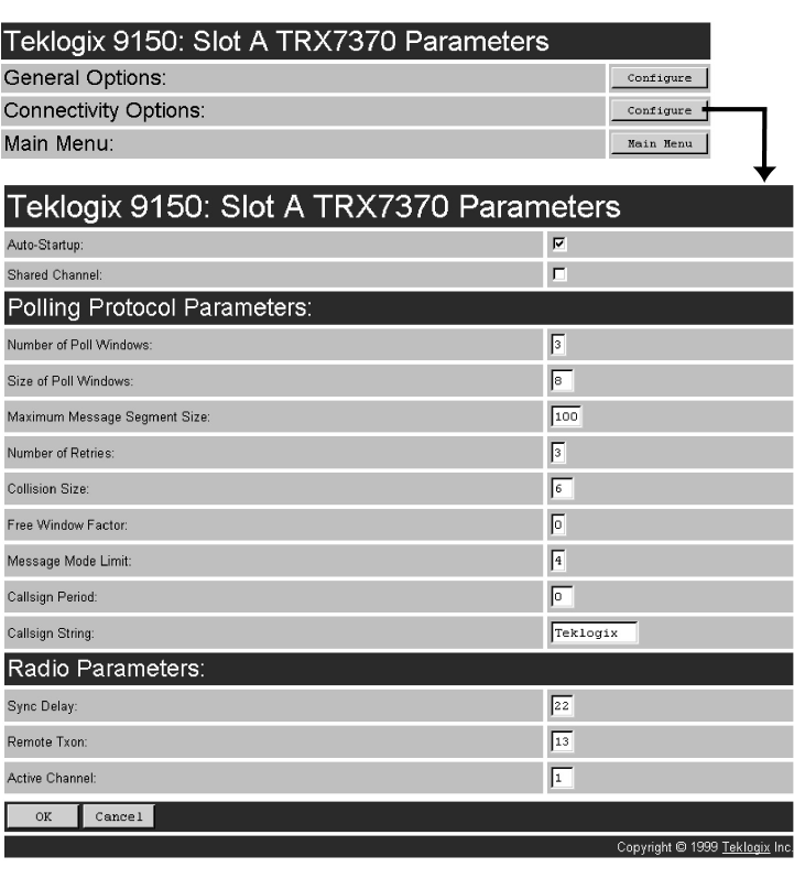
tion “Slot A: Teklogix Narrowband”, entering the “Configure” dialog box will
display the Slot A TRX7370 Parameters menu for the TRX7370 Narrow Band PC
card radio, as shown in Figure 5.4 on page 107. The Slot A TRX7370 Parameters
menu has two configuration sub-menus:
“General Options”
When you select this sub-menu, the page displayed allows you to set the operat-
ing options for the 9150 in either base station or RRM mode, and to retrieve the
radio card’s permanent communications settings.
“Connectivity Options”
When you select this sub-menu, the 9150 displays the Parameters page of the
operating mode for which the 9150 is set (base station or RRM).
Teklogix 9150 Wireless Gateway User Manual 107
Chapter 5: Base Station Configuration
Narrow Band Radio Parameters
There is also a Main Menu button. When you select this button, the 9150 displays
the Configuration Main Menu (see page 101).
Figure 5.4 Overview Of Teklogix Narrow Band Menus
Chapter 5: Base Station Configuration
Narrow Band Radio Parameters
108 Teklogix 9150 Wireless Gateway User Manual
5.2.2.1 General Options
When you select this sub-menu, the page displayed allows you to set the operating
options for the 9150, and to retrieve the TRX7370 radio card’s permanent communi-
cations settings.
Enable Card
This parameter enables the PC card ( √ ). The card may be disabled temporarily
when, for testing purposes, it is required that there be no radio interference.
Important: If changing radio types in the 9150, DO NOT “hot swap” the PC
cards: turn the 9150 off before changing the radio.
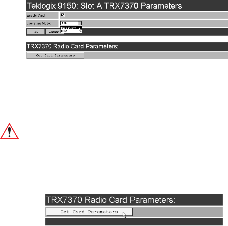
Operating Mode
This parameter allows you to set the operating mode of the 9150 as Base Station
or RRM.
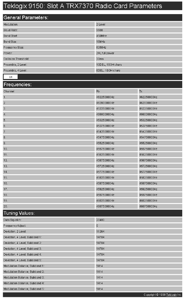
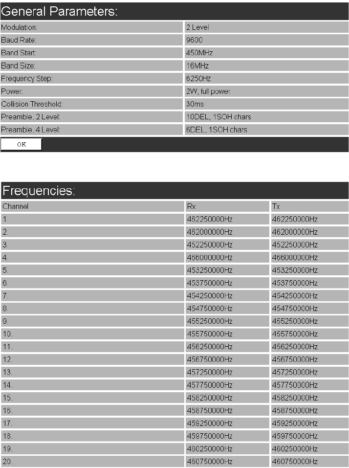
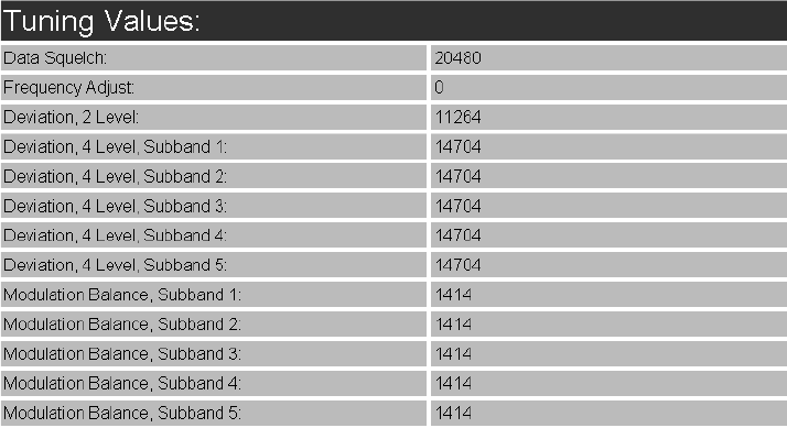
5.2.2.2 TRX7370 Radio Card Parameters
Entering the “Get Card Parameters” dialog box will open the list of General, Fre-
quencies, and Tuning Values parameters for the TRX7370 Narrow Band PC card
radio. These manufacturer’s settings are not configurable. The settings are shown on
pages 110 and 111.
Teklogix 9150 Wireless Gateway User Manual 109
Chapter 5: Base Station Configuration
Narrow Band Radio Parameters
Chapter 5: Base Station Configuration
Narrow Band Radio Parameters
110 Teklogix 9150 Wireless Gateway User Manual
General Parameters
Frequencies
Teklogix 9150 Wireless Gateway User Manual 111
Chapter 5: Base Station Configuration
Narrow Band Radio Parameters
Tuning Values
Chapter 5: Base Station Configuration
Narrow Band Radio Parameters
112 Teklogix 9150 Wireless Gateway User Manual
5.2.2.3 Connectivity Options: Base Station Mode
When you enter the Connectivity Options sub-menu for the 9150 set in base
station operating mode, the 9150 displays the Polling Protocol Parameters and
Radio Parameters.
Teklogix 9150 Wireless Gateway User Manual 113
Chapter 5: Base Station Configuration
Narrow Band Radio Parameters
Auto-Startup
This parameter enables ( √ ) polling immediately when the 9150 is rebooted.
If Auto-Startup is disabled, the 9150 will wait until polling is initialized from the
network controller.
Shared Channel
Shared Channel is only used in Holland to accommodate government requirements.
When enabled ( √ ), it imposes timing restrictions for polling. Every 2 seconds of
polling is followed by 0.5 seconds of silence—no polling occurs.
Further, if another carrier is detected on the channel, the 9150 will cease radio trans-
missions on that channel until the path is clear.
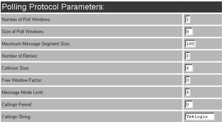
POLLING PROTOCOL PARAMETERS
Number of Poll Windows
This parameter defines the number of poll windows the 9150 will use. The value
assigned to this parameter is dependent on the number of terminals and the radio
link protocol used.
Table 5.1 on page 114 indicates how the value assigned to the Number of Poll
Windows parameter is determined.

Chapter 5: Base Station Configuration
Narrow Band Radio Parameters
114 Teklogix 9150 Wireless Gateway User Manual
Table 5.1 Number Of Poll Windows – Cellular Protocol
Size of Poll Windows
The value assigned to this parameter determines the largest message that can be
passed between the 9150 and the terminal in a normal poll window. The window
size can be adjusted to accommodate anywhere from 4 to 32 characters.
Larger windows increase the polling period and can increase the response time.
Smaller windows increase the number of message and long message polls, and can
also increase the response time.
Important: In “Cellular” mode, the minimum value for this parameter is 8.
Maximum Message Segment Size
This parameter determines the largest single message that can be passed to a
terminal in message mode or from a terminal in long message mode. In a 9150 base
station, the value entered in this parameter must be greater than or equal to the value
entered in the network controller or 9150 mini-controller. The range of this parame-
ter is between 32 and 116 characters. (Longer messages are broken into several
packets.) The default value is 100.
Number of Retries
This parameter determines how many times the 9150 attempts to resend a message
if an acknowledgement is not received from the terminal. (These retries do not
necessarily occur in consecutive polls because incomplete messages are returned to
the bottom of the message queue.) After all retries have been exhausted, the terminal
is declared “offline”. The 9150 does not transmit any messages to the terminal until
the terminal declares itself “online”. The allowable values range from 1 to 7.
Number of Terminals Minimum # of Windows
1-16 2
17-81 3
82-256 4

Teklogix 9150 Wireless Gateway User Manual 115
Chapter 5: Base Station Configuration
Narrow Band Radio Parameters
Collision Size
This parameter reduces the probability that random noise on the radio link will be
interpreted as a collision between terminals. Response time increases when the 9150
resolves collisions unnecessarily.
Collision Size places an upper limit on the number of characters that are received
prior to the receipt of an error message (CRC, CD lost, etc.). If eight is the value of
this parameter, eight or less characters followed by an error message appearing over
the radio link are considered noise. If there are more than eight characters, it is con-
sidered a collision. Acceptable values range from 3 to 15.
Free Window Factor
The value entered in this parameter determines if “free window mode” will be used.
In free window mode, all terminals that are not assigned any other window can use
the free window.
Entering a value of 0 (zero) in this parameter disables free window mode. Increas-
ing the value of this parameter increases the likelihood of a message being transmit-
ted in the free window.
Message Mode Limit
This parameter defines an upper limit to the number of messages that must be
queued for transmission before message mode polling starts. Accepted values range
from 0 to 7, where 0 disables message mode.
Note: The number of terminals and past events are also part of the algorithm
that determines whether or not to start message mode.
Callsign Period
A call sign is periodically transmitted as an audible Morse code signal. This
parameter specifies the interval in minutes between call sign transmissions.
Acceptable values range from 0 to 60. The federal agencies, Industry Canada and
the Federal Communications Commission in the United States, require that each
system transmit its own identification call sign every 15 minutes.
In countries where a call sign is not required, setting this parameter to 0 prevents the
transmission of any call signs, allowing for shorter poll time-outs in terminals and
faster channel switching.