Contents
USERS MANUAL 3
Chapter 5: Base Station Configuration
Narrow Band Radio Parameters
116 Teklogix 9150 Wireless Gateway User Manual
Callsign String
This string can be a maximum of 10 characters long. All characters are either
numbers or letters. The prefix “DE” (from) is added to the beginning of the transmit-
ted call sign.
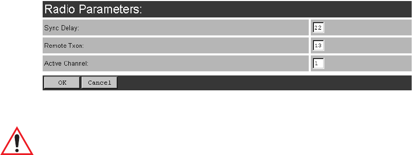
RADIO PARAMETERS
Sync Delay
Important: This parameter should not be changed from its factory setting
without a clear understanding of the timing of the radio protocol.
Sync Delay specifies the delay between the time of the base station transmission and
the first response window, measured in character times. The value assigned to this
parameter must be compatible with other base stations and terminals in the system.
The TRX7370 radio is available in either two level or four level modulation, provid-
ing baud rates of 4800 bps and 9600 bps, or 9600 bps and 19200 bps, respectively.
The default setting for a two level modulation narrow band radio, operating at 9600
baud, is 23.
The default setting for a four level modulation narrow band radio, operating at
19200 baud, is 31.
Remote Txon
Remote Txon accommodates the turn on time of the radio in terminals (remotes). It
specifies the number of fill characters sent to the radio before real data is output.
Since this parameter is based on character times, the number is dependent on the
radio link baud rate.
Teklogix 9150 Wireless Gateway User Manual 117
Chapter 5: Base Station Configuration
Narrow Band Radio Parameters
The value assigned to the Remote Txon parameter must be consistent across all
terminals and base station equipment. The allowable value range is 3 to 60.
Important: This parameter should not be changed from its factory setting
without an understanding of the timing of the radio protocol.
Active Channel
This parameter determines the operating radio channel of the 9150. This makes
the channel available for channel searching by the terminals. The channel selected
must be one of those that have been configured with frequencies, as indicated on the
TRX7370 Radio Card Parameters page. See page 110 for the list of associated chan-
nels and frequencies.
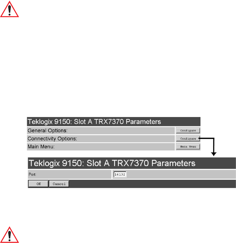
5.2.2.4 Connectivity Options: RRM Mode
When you enter the Connectivity Options sub-menu for the 9150 set in RRM operat-
ing mode, the 9150 displays the RRM parameters.
Port
This parameter allows you to enter the port number of the 9150. The port number
can range from 1024 to 32767.
Important: The port number entered here must match the port number entered
for this 9150 in the network controller’s RRM configuration.
Chapter 5: Base Station Configuration
Base Station Configuration Menu Options
118 Teklogix 9150 Wireless Gateway User Manual
5.3 Base Station Configuration Menu Options
The 9150 Wireless Gateway can operate as a base station or remote radio module
(RRM), facilitating the communications between terminals and wireless base sta-
tions and a network controller (Teklogix 9400 Network Controller or 9150 Wireless
Gateway), using a range of host platforms. Alternatively, the network controller can
be a host running a Teklogix SDK (handler). The 9150 can also act as a slave base
station to a 9150 on the network.
5.3.1 Base Stations
Base stations communicate over the radio link using Psion Teklogix proprietary
protocols. They can optionally carry IP data over these protocols. Base stations can
be connected to network controllers using TCP/IP over Ethernet networks. As a base
station communicating with terminals through a radio link, the 9150 uses the
Wireless LAN (Wlan) or Adaptive Polling/Contention RF protocols (see page 7 for
details on the protocols). The 9150 controls the radio link’s operation and timing.
Each base station uses a different radio channel, and terminals use cellular switching
to roam between stations.
The options and parameters on the following pages allow you to configure the 9150
as a master base station connected to up to 32 slave 9150 base stations over an
Ethernet network. The master 9150 is connected to a 9400 Network Controller, or
up to six hosts running TSDK (Teklogix Software Development Kit). From the Base
Stations option under Base Station Configuration (see Figure 5.2 on page 101),
entering “Configure” will open the “Configure New Base Station” page, which will
enable you to add a new slave base station to the system or change the parameters on
an existing slave base station.
Teklogix 9150 Wireless Gateway User Manual 119
Chapter 5: Base Station Configuration
Base Stations
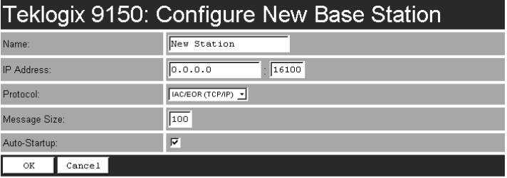
Name
The name entered in this parameter is used as an alternate way of identifying the
IP address of a slave base station.
IP Address
This parameter provides the corresponding IP address for the slave base station.
The IP Address must be a unique value so that each slave base station can be iden-
tified on the network.
The acceptable value ranges from 0.0.0.0 to 239.255.255.255.
The default value for the IP port is 16100.
Protocol
IAC/EOR (TCP/IP) is the default protocol for the Ethernet connection.
Message Size
Message Size determines the largest single message that can be passed to a
terminal. The range of this parameter is between 32 and 380 characters. (Longer
messages are broken into several packets.)
For polling protocol base stations, the upper limit is 116.
Auto-Startup
When this parameter is enabled ( √ ), the slave base stations will start polling when
the master 9150 boots up. When Auto-Startup is disabled, the base stations will not
start polling until they receive a start polling command from the host.
Chapter 5: Base Station Configuration
RRM Groups
120 Teklogix 9150 Wireless Gateway User Manual
5.3.2 RRM Groups
While the 9150 can operate as a Remote Radio Module (RRM, see “Connectivity
Options: RRM Mode” on page 117), it can also control other RRMs. For a 9150 to
control RRMs, RRM groups must be configured. Once an RRM group has been
defined, from one to four RRMs can be members of a group (see “RRM Group
Menu” on page 126).
All RRMs in a group operate on the same radio channel. The 9150 coordinates the
transmissions of all the RRMs in a group (for this reason, the controlling 9150 is
sometimes referred to as the “Timeplexing Master”).
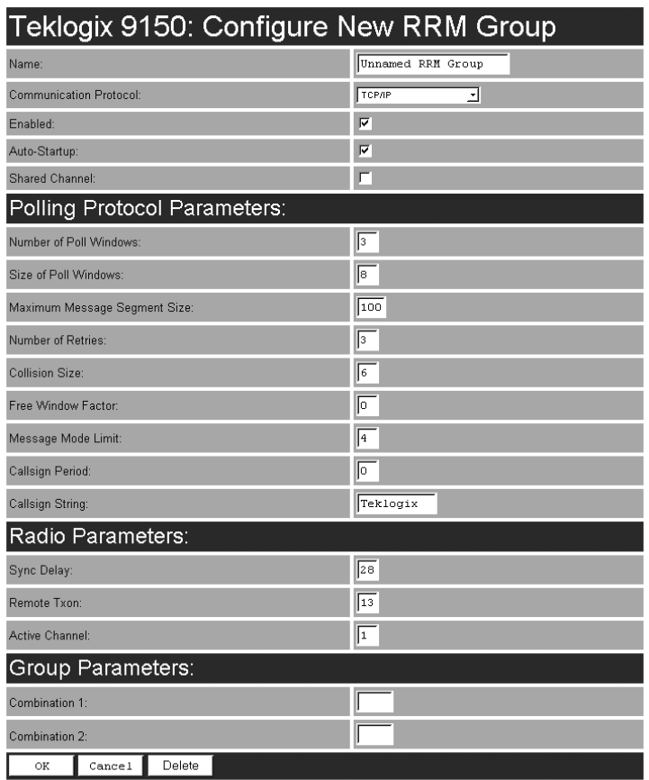
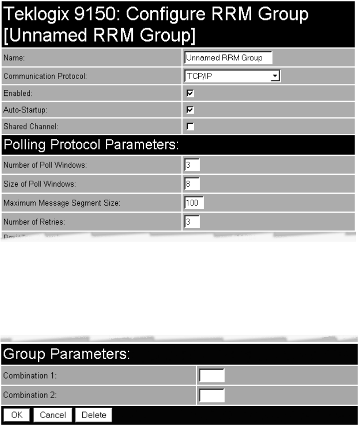
5.3.2.1 Configure New RRM Group
In this screen, shown on the next page, the user can set options for a new RRM
group. Each RRM must be a member of an RRM group; there may be more than one
RRM group configured in the 9150. An RRM group may contain from one to
four RRMs.
This screen is very similar to the one in “Connectivity Options: Base Station Mode”
on page 112, the difference being that the parameters configured in those radio
menus apply to the TRX7370 radio resident in the 9150, while the parameters con-
figured here apply to the other, remote 9150s (the RRMs).
Teklogix 9150 Wireless Gateway User Manual 121
Chapter 5: Base Station Configuration
RRM Groups
Name
This textbox allows the user to enter a name for the new RRM group. The value is
any text string. The default is Unnamed RRM Group.

Chapter 5: Base Station Configuration
RRM Groups
122 Teklogix 9150 Wireless Gateway User Manual
Communication Protocol
This listbox allows you to select the protocol to be used for the connection to this
RRM group. The default is the TCP/IP protocol.
Enabled
The Enabled option must be turned on ( √ ) for the 9150 to function as an RRM
group controller. If this option is disabled, the 9150 automatically goes into base
station mode.
Auto-Startup
When this parameter is enabled ( √ ), the 9150 establishes communication with the
RRMs in this RRM group when it boots, and starts polling automatically.
When Auto-Startup is disabled, the 9150 establishes communication with the
RRMs in this group when it boots, but does not start polling in this RRM group until
a start polling command is received from the host.
Polling starts if at least one of the RRMs in the RRM group is operating when the
9150 boots.
Shared Channel
If this parameter is enabled ( √ ), the 9150 checks for other traffic on the radio
channel used by this RRM group, before polling.
If this parameter is disabled, the 9150 assumes that it has exclusive use of the radio
channel for this RRM group, and polls without checking for radio traffic.
This parameter is required for systems installed in the Netherlands.
POLLING PROTOCOL PARAMETERS
Warning: These parameters are pre-configured for your system, and should
not be changed without a proper understanding of how they affect
the radio link.
Teklogix 9150 Wireless Gateway User Manual 123
Chapter 5: Base Station Configuration
RRM Groups
Number of Poll Windows
This textbox allows the user to specify the number of poll windows in which the
RRM listens for terminal responses after sending a poll. The allowable values range
from 2 to 4. The default value is 3.
Size of Poll Windows
This textbox allows the user to specify the size of the poll windows in which the
RRMs of this RRM group listen for terminal replies. The allowable values range
from 5 to 32. The default value is 8.
Maximum Message Segment Size
This textbox allows the user to specify the size of the largest message segment, in
bytes, that will be sent over the Teklogix radio network. Larger messages are broken
into parts. The allowable values range from 32 to 116. The default value is 100.
Number of Retries
This textbox allows the user to specify the number of times the RRM retransmits a
message to a terminal, after receiving no acknowledgement from the terminal,
before it declares the terminal offline. The allowable values range from 1 to 7. The
default value is 3.
Collision Size
This textbox allows the user to specify the smallest number of characters of noise
received by the RRM, that will be interpreted as interfering transmissions from
Teklogix equipment. When this threshold is exceeded, the RRM starts collision
resolution. The allowable values range from 3 to 10. The default value is 6.
Free Window Factor
This textbox allows the user to specify the probability that the RRM will include a
free window in its poll, during which any terminal may transmit. The allowable
values range from 0 to 7. The default value is 0.

Chapter 5: Base Station Configuration
RRM Groups
124 Teklogix 9150 Wireless Gateway User Manual
Message Mode Limit
This textbox allows the user to specify the probability of including a message-mode
poll in its poll transmission. The allowable values range from 3 to 7. The default
value is 4.
Callsign Period
This textbox allows the user to specify the amount of time between transmissions of
the callsign. This parameter is in minutes. A value of 0 (zero) indicates that no call-
sign is transmitted. The allowable values range from 0 to 60. The default value is 0.
Callsign String
This textbox allows the user to specify the text to be transmitted as the RRM’s call-
sign. The text is transmitted as Morse code. The default value is Teklogix.
RADIO PARAMETERS
Because some of the radio parameters are identical for a given group of timeplexed
RRMs, they may be configured by the user once on the 9150; the 9150 then passes
them to the RRMs in the group. These parameters include the synchronization delay
(Sync Delay), the remote transmit on-time (Remote Txon), and the channel number
to be used (Active Channel).
Although the TRX7370 narrow band radio in each RRM in the group is configured
separately, the 9150 assumes they will be configured identically. To ensure this, the
9150 looks at certain parameters returned by each of the RRMs. These parameters
include the radio baud rate and the transmit-on time.
These parameters are compared against the values returned by other RRMs within
the same group. Error messages are displayed should these values not match, but the
worst case value is chosen for use.
Warning: These parameters are pre-configured for your system, and should
not be changed without a proper understanding of how they affect
the radio link.
Sync Delay
This textbox allows the user to specify the number of delay characters inserted
between the RRM’s transmission and the first response window. The allowable
values range from 3 to 45. The default value is 28.

Teklogix 9150 Wireless Gateway User Manual 125
Chapter 5: Base Station Configuration
RRM Groups
Remote Txon
This textbox allows the user to specify the number of fill characters sent by the ter-
minal radios before the terminals send message data. The allowable values range
from 3 to 32. The default value is 13.
Active Channel
This textbox allows the user to specify the radio channel to be used by all the RRMs
in the RRM group. The allowable values range from 1 to 20. The default value is 1.
GROUP PARAMETERS
Combination
These textboxes allow the user to specify RRM subgroups called combinations.
If the coverage areas of two or more of the RRMs in this RRM group do not overlap,
the non-overlapping RRMs may poll at the same time. This improves system
response time and reduces the amount of signalling on the network.
As an example, if the RRM group has 3 RRMs, and RRMs 1 and 3 don't overlap,
RRMs 1 and 3 may be placed in one subgroup (Combination 1). They will then poll
simultaneously. RRM 2 may be placed in another subgroup (Combination 2).
Polling alternates between the two subgroups.
To configure a combination, place the numbers of the RRMs in the textbox for that
combination. The numbers correspond to the numbers of the RRMs named in the
RRM list on the RRM Group Menu (see page 126). For instance, “13” in the textbox
for Combination 1 places RRMs 1 and 3 in that subgroup.
Note: When configuring RRM combinations, make sure the configured RRMs are
sequential, and are not missing numbers, which can happen when RRMs
are deleted and added. The combinations use the RRMs in the order that
they appear in the list, not how they are numbered in the list.
RRMs that are not assigned to combinations poll individually, after the combina-
tions poll.
Chapter 5: Base Station Configuration
RRM Groups
126 Teklogix 9150 Wireless Gateway User Manual
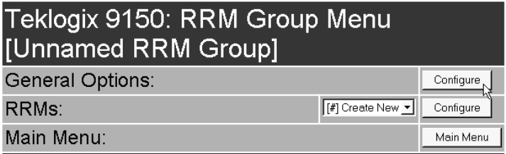
5.3.2.2 RRM Group Menu
When the user chooses an existing RRM group from the RRM Groups listbox in the
Configuration Main Menu page, pressing the Configure button displays the RRM
Group Menu.
The RRM Group Menu has two sub-menus:
General Options
When the user presses this Configure button, the 9150 displays the
Configure Existing RRM Group screen.
RRMs
When the user selects the name of an existing RRM from the listbox, then
presses this Configure button, the 9150 displays the RRM Options screen for
that RRM.
There is also a selection in the listbox, Create New, for adding a new RRM.
The RRM Group Menu also has a Main Menu button to return to the Configuration
Main Menu page.
Teklogix 9150 Wireless Gateway User Manual 127
Chapter 5: Base Station Configuration
RRM Groups
GENERAL OPTIONS: CONFIGURE RRM GROUP
In this screen, the user can select general options for this RRM group. The options in
this screen are the same as the options in the Configure New RRM Group screen (see
page 120). The Delete button at the bottom of the screen allows you to delete the
currently-displayed RRM Group from the RRM Groups list.
When choosing to delete an RRM Group, you will be prompted for confirmation of
the deletion, which will give you the opportunity to cancel the action.
Chapter 5: Base Station Configuration
Radio Link Features
128 Teklogix 9150 Wireless Gateway User Manual
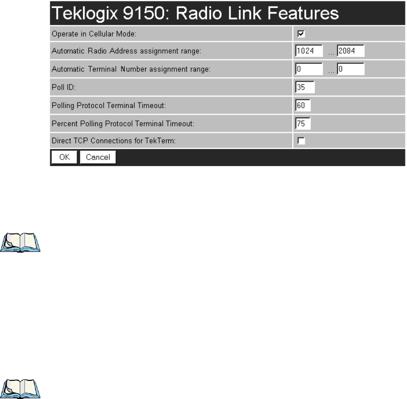
5.3.3 Radio Link Features
From the Radio Link Features option under Base Station Configuration (see Figure
5.2 on page 101), entering “Configure” will open the “Radio Link Features” page
for the polling and cellular parameters.
Operate in Cellular Mode
To operate as a Wlan base station, this parameter should be enabled ( √ ). For further
information see “Wlan Protocol” on page 11.
Note: The 9400 Network Controller must also be set to cellular mode.
Automatic Radio Address Assignment Range
Each Teklogix terminal using the radio link has a unique radio address number,
which can be assigned automatically by the 9150 by enabling this parameter.
Currently this feature is only supported through the 802.IQ protocol (for informa-
tion on 802.IQ configuration, see pages 64 and 192).
To enable this parameter, the values for the first and last radio address numbers
must lie between 1 and 3840. The default values for the range are 1024 ... 2084.
To disable the parameter, set the values to 0.
Notes: When enabling this parameter:
1. Direct TCP Connections for TekTerm must be disabled (see page 130).
2. The Auto ID parameter in the terminal must be enabled in order for
the radio address to be automatically assigned.

Teklogix 9150 Wireless Gateway User Manual 129
Chapter 5: Base Station Configuration
Radio Link Features
3. Do not enable Auto Startup (see page 65) on any of the 9150 base sta-
tions running 802.IQ with sessions using Automatic Radio Address
Assignment Range and Automatic Terminal Number Assignment
Range.
Automatic Terminal Number Assignment Range
A terminal number is assigned for every TESS and ANSI application session
created in a terminal. This number defines the terminal number for each session and
uniquely identifies all transmissions to and from that session.
To enable this parameter, the values for the first and last terminal numbers must lie
between 1 and 3840. The default values for the range are 0 ... 0. To disable the
parameter, set the values to default.
Notes: When enabling this parameter:
1. Direct TCP Connections for TekTerm must be disabled (see page 130).
2. The Auto Session parameter in the terminal must be enabled in order
for the terminal session number to be automatically assigned.
3. Do not enable Auto Startup (see page 65) on any of the 9150 base sta-
tions running 802.IQ with sessions using Automatic Radio Address
Assignment Range and Automatic Terminal Number Assignment
Range.
Poll ID
In Wlan protocol, this is a unique identifying number set only in a 9150 master base
station, 9150 mini-controller or a network controller, which is used in the poll
header when polling terminals. Poll ID is set by Psion Teklogix personnel.
In Adaptive Polling/Contention protocol for narrow band radios, Poll ID is used to
assign a unique address to each base station. As the terminals move from one base
station to another, this address is transmitted by the base stations to the terminals,
identifying each 9150 in a multiple base station system.

Chapter 5: Base Station Configuration
Radio Link Features
130 Teklogix 9150 Wireless Gateway User Manual
Polling Protocol Terminal Timeout
This parameter determines the time in minutes that a terminal can be inactive before
the 9150 declares it offline. Before this happens, the terminal will be declared
offline by the Percent Polling Protocol Terminal Timeout parameter (see below).
After the terminal is removed from the system, it will need to re-initialize in order to
communicate with the 9150. This parameter reduces the overhead on the radio link
caused when terminals which are not communicating are supported.
The allowable values range from 1 to 240.
Note: This parameter is not relevant for Wlan.
Percent Polling Protocol Terminal Timeout
This parameter determines the time that a terminal is allowed to be inactive before
the 9150 declares it offline. This time is expressed as a percentage of the Polling
Protocol Terminal Timeout parameter (see above). For example, if the Polling Proto-
col Terminal Timeout is 60, and this parameter is set to 75%, then the timeout would
be 60 min x 75% = 45 minutes.
An offline terminal is still considered part of the system. Messages to offline termi-
nals are queued at the 9150. The terminal remains offline until it transmits an online
message.
Values for this parameter range from 50 to 90.
Direct TCP Connections for TekTerm
Enabling this parameter allows the TekTerm program resident in Teklogix
terminals to connect directly to the 9150, when it is acting as a base station to
a host via TCP/IP.
Teklogix 9150 Wireless Gateway User Manual 131
Chapter 5: Base Station Configuration
Hosts Menu
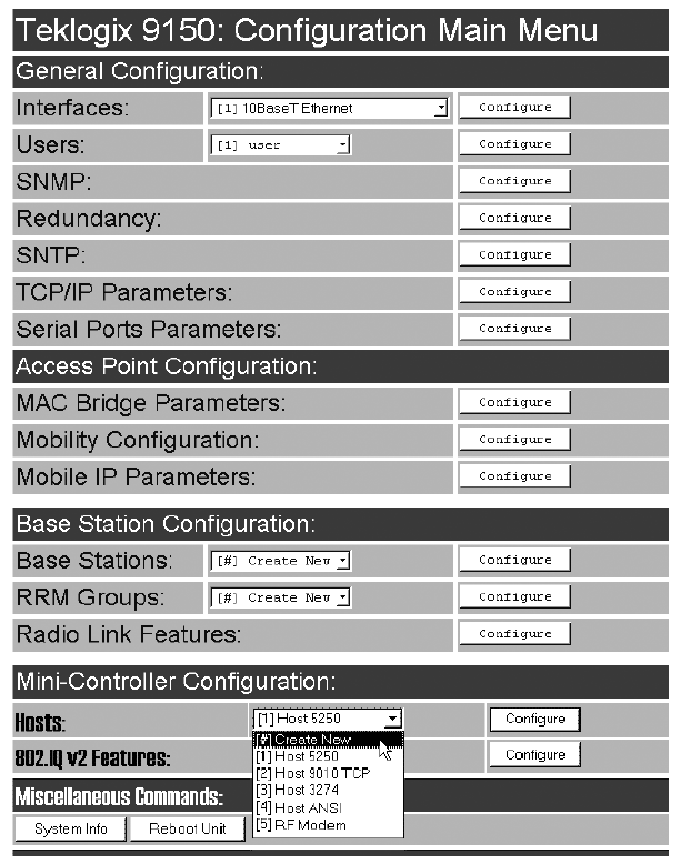
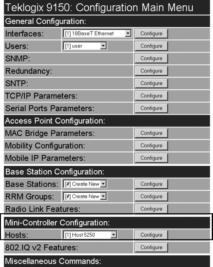
5.4 Hosts Menu
When the 9150 acts as a base station, it must communicate with a “host” - a 9400
Network Controller, or a host computer using a Teklogix Software Development Kit
(TSDK). The drop-down menu in the Mini-Controller Configuration: Hosts option
in the Configuration Main Menu page shows the host names present on the system.
Up to six hosts can be supported. A “host” must be configured for each master
network controller, TSDK host, or master base station that communicates with
the 9150.
Chapter 5: Base Station Configuration
Hosts Menu
132 Teklogix 9150 Wireless Gateway User Manual
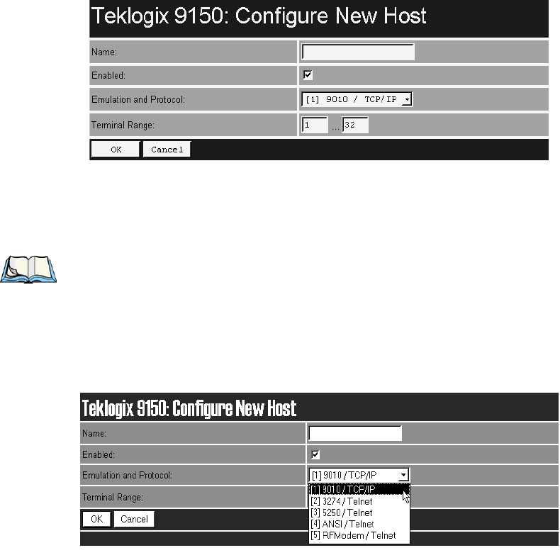
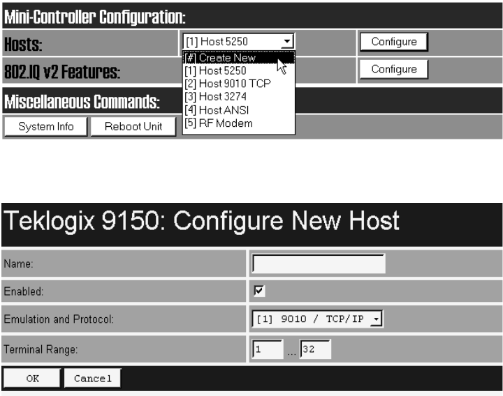
Opening the “Configure” dialog box for a selected host lists the parameters that can
be modified or deleted for that host. New hosts can be added by selecting “[#]
Create New” in the drop-down menu before entering the “Configure” dialog box.
Name
This parameter indicates the assigned host name. The host name also appears on the
RF terminal when switching between hosts in a multiple-host environment.
Note: The name must not contain space characters.
Enabled
The Enabled option must be turned on ( √ ) for terminals to communicate with this host.
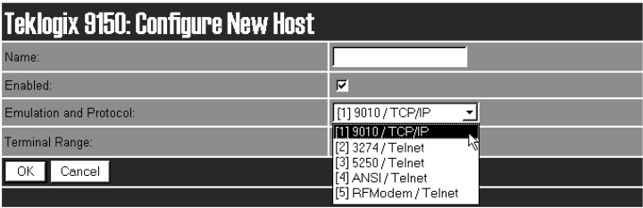
Emulation and Protocol
This drop-down menu provides a list of host emulations and communication
protocols supported by the 9150. Protocols are the methods by which terminals
communicate with host computers over various physical media such as Ethernet and
radio-link connections.
Teklogix 9150 Wireless Gateway User Manual 133
Chapter 5: Base Station Configuration
Hosts Menu
The supported emulations with their respective protocols are:
• 9010/ TCP/IP (See page 135 for configuration parameters).
• 3274/Telnet (See pages 149 to 164 for Configuration Parameters).
• 5250/Telnet (See pages 165 to 179 for Configuration Parameters).
• ANSI/Telnet (See pages 180 to 190 for Configuration Parameters).
• RF Modem (See page 191 for Configuration Parameters).
When the 9150 functions as a base station, it communicates with a 9010/ TCP/IP
host. The 9010 protocol is a proprietary asynchronous protocol developed by Psion
Teklogix which uses TESS (Teklogix Screen Subsystem) or ANSI data streams to
communicate with terminals. For detailed information, please refer to the appropriate
Teklogix User Manual for: 9400 Network Controller, TSDK, TESS or ANSI.
However, when the 9150 acts as a mini-controller, it uses the 3274 and 5250 emula-
tion protocols to communicate with IBM hosts, or the ANSI emulation protocol to
communicate with ANSI hosts. For detailed information on configuring the 9150 as
a mini-controller, please refer to Chapter 6: “Mini-Controller Configuration”.
Terminal Range
The values entered in this parameter designate the first and last terminals in the
range of terminals that will communicate with the host. These terminal numbers are
mapped to this particular host.
Chapter 5: Base Station Configuration
Host Menu Options
134 Teklogix 9150 Wireless Gateway User Manual
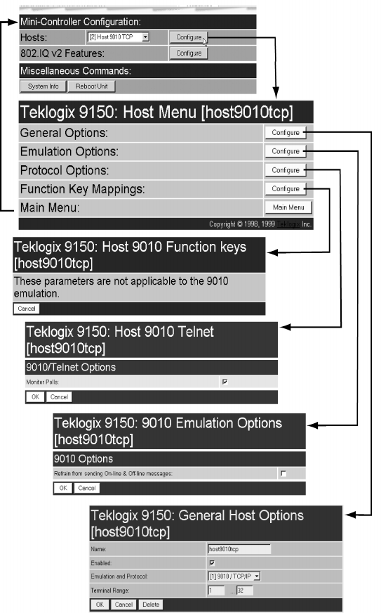
5.5 Host Menu Options
When you choose an existing host from the Hosts listbox and then select the Config-
ure button, the 9150 displays the Host Menu.
Figure 5.5 Overview Of Host Menus For 9010 / TCP/IP
Teklogix 9150 Wireless Gateway User Manual 135
Chapter 5: Base Station Configuration
9010 / TCP/IP
The Host Menu has four configuration sub-menus:
“General Host Options”
When you select this sub-menu, the 9150 displays the General Options page for
the host.
“Emulation Options”
When you select this sub-menu, the 9150 displays the Emulation Options page
for the host. This page may vary depending on the type of emulation and proto-
col selected for the host.
“Protocol Options”
When you select this sub-menu, the 9150 displays the Protocol Options page for
the host. This page may vary depending on the type of emulation and protocol
selected for the host.
“Function Key Mappings” (3274, 5250, ANSI emulations only)
When you select this sub-menu, the 9150 displays the Function Key Mapping
page for the host. This page may vary depending on the type of emulation and
protocol selected for the host.
There is also a Main Menu button. When you select this button, the 9150 displays
the Configuration Main Menu (see page 101).
5.5.1 9010 / TCP/IP
For an overview of Host menus for 9010/TCP/IP, refer to Figure 5.5 on page 134.
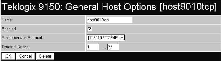
5.5.1.1 General Host Options
In this screen, you can select general options for the host connection. The host con-
nection may also be deleted. When choosing to delete a host from the Hosts list, you
will be prompted for confirmation of the deletion, which will give you the opportu-
nity to cancel the action.
Chapter 5: Base Station Configuration
9010 / TCP/IP
136 Teklogix 9150 Wireless Gateway User Manual
Name
This parameter allows you to enter a name for the new host.
Enabled
The Enabled option must be turned on ( √ ) for terminals to communicate with
this host.
Emulation and Protocol
This parameter allows you to select the emulation and protocol to be used for the
connection to this host. For a network connection, use 9010/ TCP/IP.
Terminal Range
This parameter allows you to specify the range of terminals which will communi-
cate with this host. The left-hand textbox contains the lowest terminal number which
is allowed to communicate with the host; the right-hand textbox contains the highest
terminal number. Terminal numbers may range from 1 to 3840.
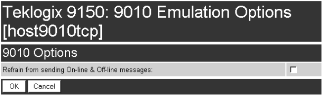
5.5.1.2 Emulation Options
Refrain from sending On-line & Off-line messages
If this parameter is enabled ( √ ), the 9150 base station does not notify the host if
the status of a terminal changes between offline and online. If this parameter is
disabled, the 9150 does notify the host regarding any terminal status changes.
The default for this parameter is disabled.
Teklogix 9150 Wireless Gateway User Manual 137
Chapter 5: Base Station Configuration
9010 / TCP/IP
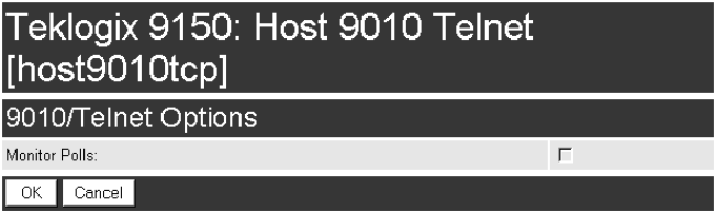
5.5.1.3 Protocol Options
9010/Telnet Options: Monitor Polls
Hosts usually send messages or null polls to the 9150 within a period of approxi-
mately 40 seconds. If the parameter is enabled ( √ ), the 9150 base station monitors
messages and polls from this host; if it does not receive a message or poll within 40
seconds, it closes the connection. The default for this parameter is disabled.
5.5.1.4 Function Key Mappings
These parameters are not applicable to the 9010 / TCP/IP emulation.

Teklogix 9150 Wireless Gateway User Manual 139
MINI-CONTROLLER CONFIGURATION 6
6.1 Overview.............................141
6.2 Mini-Controller Configuration Menu..............143
6.3 Hosts Menu ...........................144
6.4 Host Menu Options .......................146
6.4.1 General Options . . . . . . . . . . . . . . . . . . 148
6.4.2 9010 Emulations . . . . . . . . . . . . . . . . . . 149
6.4.3 3274/Telnet. . . . . . . . . . . . . . . . . . . . . 149
6.4.3.1 Emulation Options. . . . . . . . . . . . . . 149
6.4.3.2 Protocol Options. . . . . . . . . . . . . . . 161
6.4.3.3 Function Key Mappings . . . . . . . . . . . 164
6.4.4 5250/Telnet. . . . . . . . . . . . . . . . . . . . . 165
6.4.4.1 Emulation Options. . . . . . . . . . . . . . 165
6.4.4.2 Protocol Options. . . . . . . . . . . . . . . 176
6.4.4.3 Function Key Mappings . . . . . . . . . . . 179
6.4.5 ANSI/Telnet....................180
6.4.5.1 Emulation Options. . . . . . . . . . . . . . 180
6.4.5.2 Protocol Options. . . . . . . . . . . . . . . 183
6.4.5.3 Function Key Mappings . . . . . . . . . . . 190
6.4.6 RF Modem/Telnet.................191
6.4.6.1 Emulation Options. . . . . . . . . . . . . . 191
6.4.6.2 ANSI Telnet Protocol Options (RF Modem) 191
6.4.6.3 Function Key Mappings . . . . . . . . . . . 192
6.5 802.IQ V2 Features Menu . . ..................192
6.5.1 802.IQ Version 2 Configuration . . . . . . . . . . 192
6.5.1.1 802.IQ v1/v2 Common Features . . . . . . 193
6.5.1.2 802.IQ v2 Configuration Submenu . . . . . 194

Teklogix 9150 Wireless Gateway User Manual 141
Chapter 6: Mini-Controller Configuration
Overview
6.1 Overview
The network controller in a Teklogix system performs a number of important tasks.
One of these tasks is emulation: the translation of data between the protocol of the
host computer and the protocol used by Teklogix terminals.
The data which is sent from a host computer to a terminal to provide its display, and
returned to the host as a result of operations at the terminal, is called a data stream.
Host computers can provide data streams of various types to their terminals.
Teklogix terminals can directly accept only two types of data stream: TESS and
ANSI. TESS (Teklogix Screen Subsystem) is the proprietary data stream used by
Teklogix terminals. ANSI data streams are a standard type of data stream used by
wired ANSI terminals. Other types of data stream provided by the host must be
converted into TESS or ANSI before Teklogix terminals can work with them. This
translation is done by emulation software in a network controller.
The 9150 is equipped with emulation capabilities, allowing it to act as a mini-
controller. When a 9150 is configured as a mini-controller, Teklogix terminals can
emulate an ANSI, 5250 or 3274 terminal via a 9150 rather than through a 9400
Network Controller. Using the RF Modem/Telnet emulation, the 9150 can also
communicate with a Teklogix 6040 RF Modem.
Important: 9150s acting as mini-controllers are designed for small, low-
transaction sites. A 9400 Network Controller is required for
systems that support more than 50 terminals.
Acting as a mini-controller, the 9150 can support up to 32 additional networked base
stations and up to 50 terminals. A 9150 mini-controller can also manage wireless
LAN configurations.
A 9150 configured as a mini-controller can support the following emulations:
• 5250 emulation using TCP/IP over an Ethernet LAN.
• 3274 emulation using TCP/IP over an Ethernet LAN.
• ANSI emulation using TCP/IP over an Ethernet LAN.
• RF Modem emulation using TCP/IP over an Ethernet LAN.
Note: The 9150 main parameters should first be set up as described in Chapter 3:
“9150 Main Configuration”.
The 9150 can also be integrated into a mapRF system, using 802.IQv2 protocol (for
details, please refer to the “802.IQ V2 Features Menu” on page192).
Chapter 6: Mini-Controller Configuration
Overview
142 Teklogix 9150 Wireless Gateway User Manual
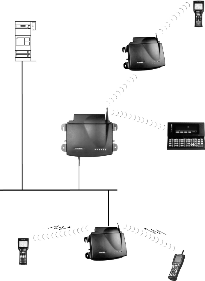
Figure 6.1 9150 Mini-Controller Configuration
Hand-Held
RF Terminal
7035
Hand-Held
RF Terminal
Mini-Controller
9150 Wireless Gateway
Base Station and Access Point
9150 Wireless Gateway
7030
7030 Hand-Held
RF Terminal
802.11 / 2.4 GHz
902 MHz
9150
Wireless Gateway
ETHERNET
TCP/IP
8055 Vehicle-Mount
RF Terminal
HOST
Teklogix 9150 Wireless Gateway User Manual 143
Chapter 6: Mini-Controller Configuration
Mini-Controller Configuration Menu
6.2 Mini-Controller Configuration Menu
For operation as a mini-controller, the parameters in the Hosts pages under Mini-
Controller Configuration should be set appropriately. The Hosts options are found
on the Configuration Main Menu page. For information on configuring radio proto-
col parameters, please refer to “Radio Link Features” on page 128.
Chapter 6: Mini-Controller Configuration
Hosts Menu
144 Teklogix 9150 Wireless Gateway User Manual
6.3 Hosts Menu
The drop-down menu in this option shows the host names present on the system. Up
to six hosts can be supported. A “host” must be configured for each host that com-
municates with the 9150 mini-controller. Opening the Configure dialog box for a
selected host lists the parameters that can be modified or deleted for that host.
New hosts can be added by selecting “[#] Create New” in the drop-down menu
before entering the Configure dialog box.
Name
This parameter indicates the assigned host name. The host name also appears on the
RF terminal when switching between hosts in a multiple-host environment.
Enabled
The Enabled option must be turned on ( √ ) for terminals to communicate with
this host.
Teklogix 9150 Wireless Gateway User Manual 145
Chapter 6: Mini-Controller Configuration
Hosts Menu
Emulation and Protocol
This drop-down menu provides a list of host emulations and communication proto-
cols supported by the 9150. Working with Teklogix terminals and base stations, the
9150 can emulate IBM 3278-2, 5251-11, and 5555-B01 terminals, as well as ANSI
terminals and RF Modems.
Protocols are the methods by which terminals communicate with host computers
over various media such as Ethernet and radio-link connections. The 9150 supports
the TCP/IP protocol. The supported emulations with their respective protocols are:
• 9010/ TCP/IP (See page 149 for Configuration Parameters).
• 3274/Telnet (See pages 149 to 164 for Configuration Parameters).
• 5250/Telnet (See pages 165 to 179 for Configuration Parameters).
• ANSI/Telnet (See pages 180 to 190 for Configuration Parameters).
• RF Modem/Telnet (See page 191 for Configuration Parameters).
When the 9150 acts as a base station, it uses the 9010 emulation (a proprietary
asynchronous protocol developed by Psion Teklogix) to communicate with a 9400
Network Controller or a host using a Teklogix Software Development Kit (TSDK).
For detailed information on configuring the 9150 as a base station, please refer to
Chapter 5: “Base Station Configuration”.
When the 9150 acts as a mini-controller, it uses the 3274 and 5250 emulation
protocols to communicate with IBM hosts, or the ANSI emulation protocol to com-
municate with ANSI terminals. To communicate with a Teklogix 6040 RF Modem,
the 9150 uses the RF Modem/Telnet emulation protocol.
Terminal Range
The values entered in this parameter designate the first and last terminals in the
range of terminals that will communicate with the host. These terminal numbers are
mapped to this particular host. Terminal numbers may range from 1 to 50.
Chapter 6: Mini-Controller Configuration
Host Menu Options
146 Teklogix 9150 Wireless Gateway User Manual
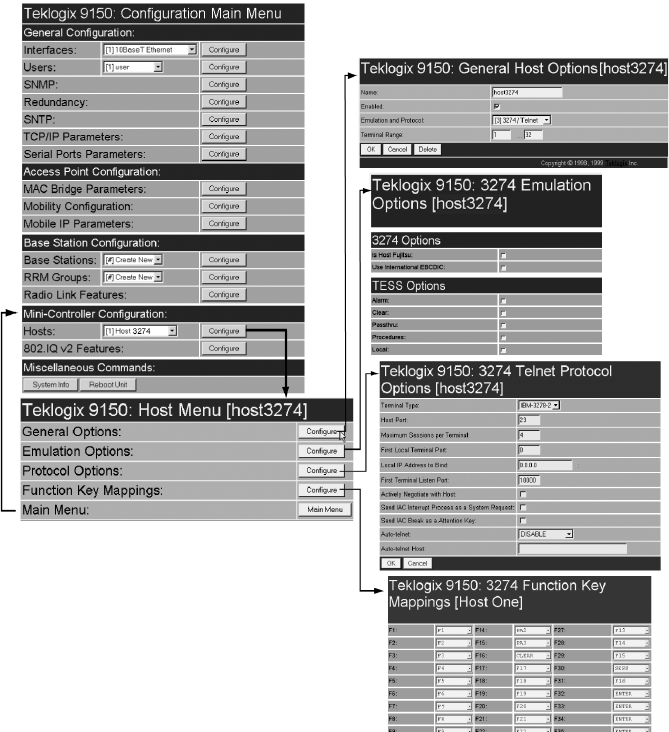
6.4 Host Menu Options
When you choose an existing host name from the Hosts listbox and then select the
Configure button, the 9150 displays the Host Menu. The Host Menu presents the
options for four sub-menus: General Host Options, Emulation Options, Protocol
Options, and Function Key Mappings. There is also a Main Menu button. When
you select this button, the 9150 displays the Configuration Main Menu page
(see page 143 for an enlarged illustration).
Figure 6.2 Overview Of Host Menu and Sub-Menus

Teklogix 9150 Wireless Gateway User Manual 147
Chapter 6: Mini-Controller Configuration
Host Menu Options
As illustrated in Figure 6.2 on page 146, the four configuration sub-menus display
the following options:
“General Options”
When you select this sub-menu, the 9150 displays the General Options page for
the host.
“Emulation Options”
When you select this sub-menu, the 9150 displays the Emulation Options page
for the host. This page may vary depending on the type of emulation and proto-
col selected for the host.
“Protocol Options”
When you select this sub-menu, the 9150 displays the Protocol Options page
for the host. This page may vary depending on the type of emulation and proto-
col selected for the host.
“Function Key Mappings”
When you select this sub-menu, the 9150 displays the Function Key Mappings
page for the host. This page may vary depending on the type of emulation and
protocol selected for the host.
Note: The Function Key Mappings parameters are not applicable to either of
the 9010 emulations.
Chapter 6: Mini-Controller Configuration
General Options
148 Teklogix 9150 Wireless Gateway User Manual
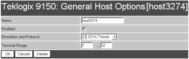
6.4.1 General Options
In this screen, you can select general options for the host connection. The host con-
nection may also be deleted (see “Delete” on page 149).
Name
This parameter allows you to enter a name for the new host.
Enabled
The Enabled option must be turned on ( √ ) for terminals to communicate with
this host.
Emulation and Protocol
This parameter allows you to select the emulation and protocol to be used for the
connection to this host. Available combinations of emulation and protocol are:
3274/Telnet, 5250/Telnet, ANSI/Telnet, RF Modem/Telnet.
Terminal Range
This parameter allows you to specify the range of terminals which will communi-
cate with this host. The left-hand textbox contains the lowest terminal number which
is allowed to communicate with the host; the right-hand textbox contains the highest
terminal number. Terminal numbers may range from 1 to 50.
Teklogix 9150 Wireless Gateway User Manual 149
Chapter 6: Mini-Controller Configuration
9010 Emulations
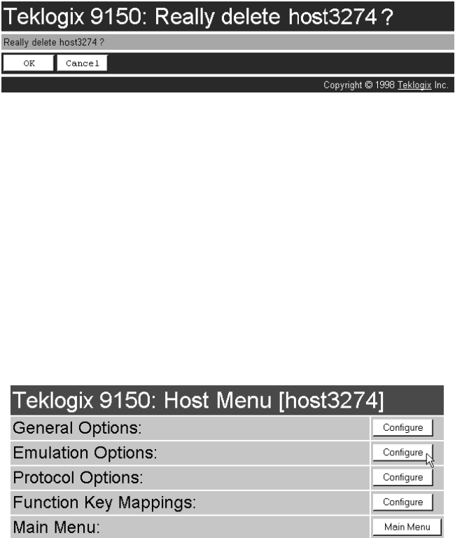
Delete
When choosing to delete a host from the Hosts list, you will be prompted for confir-
mation of the deletion, which will give you the opportunity to cancel the action.
6.4.2 9010 Emulations
When the 9150 acts as a base station, it uses the 9010 protocol (a proprietary asyn-
chronous protocol developed by Psion Teklogix) to communicate with a 9400
Network Controller, or a host using a Teklogix Software Development Kit (TSDK).
For detailed information on configuring the 9150 as a base station, please refer to
Chapter 5: “Base Station Configuration”.
6.4.3 3274/Telnet
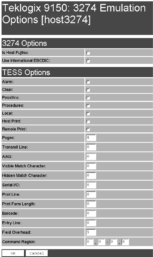
6.4.3.1 Emulation Options
When in the Host Menu for a 3274/Telnet host, selecting the Configure button for
the Emulation Options page will open the 9150 mini-controller’s 3274/Telnet
version of that page.
With IBM 3274, or IBM 5250 emulation, the 9150 mini-controller converts the
application data stream from the host to TESS (Teklogix Screen Subsystem)
commands. Some of the parameters in this page govern the conversion of the host
screens to TESS.
Chapter 6: Mini-Controller Configuration
3274/Telnet
150 Teklogix 9150 Wireless Gateway User Manual

Teklogix 9150 Wireless Gateway User Manual 151
Chapter 6: Mini-Controller Configuration
3274/Telnet
Is Host Fujitsu
If this parameter is enabled, the 9150 mini-controller expects the data from the host
to contain commands, etc., native to a Fujitsu host. Enabling this parameter causes
the standard IBM formatting codes (for start of field, setting buffers, etc.) to be
replaced by the codes used by Fujitsu host computers.
Use International EBCDIC
If this parameter is enabled, the 9150 mini-controller uses the International
EBCDIC character set, swapping the positions of the ! and ] characters.
Alarm
When this parameter is enabled, terminals beep when the word “ALARM” appears
on the application screen in the location specified by the Command Region parame-
ter (see page 160). The word “ALARM” should be a display-only field.
Note: The Command Region parameter must be enabled for this
parameter to work.
Clear
If this parameter is enabled, the 9150 mini-controller creates an empty entry field
for an entry field that is filled with spaces.
Some host applications rely on the video attributes of displayed characters to high-
light fields, particularly entry fields. For example, the application screen may define
all entry fields with reverse video and fill the field with spaces. This is effective on
terminals that support reverse video, but on terminals that do not, it can make the
field invisible since it is made up entirely of spaces.
By default, all empty entry fields displayed at the Teklogix terminal are highlighted
by the “entry character” chosen in the terminal’s configuration (not all Teklogix ter-
minals support video attributes).
Note: This operation is only performed on screens received from the host. Data
sent to the host remains unaffected.
Passthru
If this parameter is enabled, the 9150 allows the host to send data directly to the RF
terminal’s serial port. This is most commonly used for printing.

Chapter 6: Mini-Controller Configuration
3274/Telnet
152 Teklogix 9150 Wireless Gateway User Manual
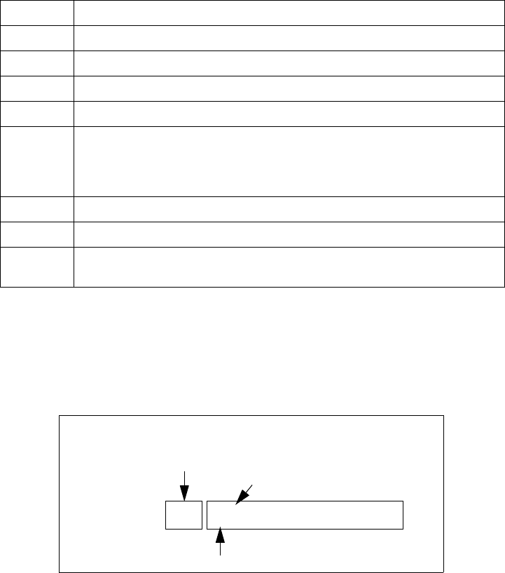
Preparing Host Screens for Pass-Through
On the screen to be sent through the terminal serial port, the word PASSTHRU (in
capital letters) must appear on the first line, starting on the second column. The
actual data to be sent to the terminal may start anywhere below the first line.
With 5250 or 3274 emulations, attributes occupy a position in the screen buffer. An
attribute placed between column 2 and the end of the word “PASSTHRU” will
‘push’ all following characters one position to the right. Therefore, any required
attributes should occupy column 1 of the first line (just preceding the word
“PASSTHRU”).
Example:
where @ is an attribute.
When the 9150 is finished sending the data to the terminal’s printer, it will send an
ENTER key to the host. The host must wait for the ENTER key before sending any
more screens (including other PASSTHRU screens) to this terminal.
Note: Refer to the Terminals User Manual for information about setting
parameters on the terminal for pass-through.
Procedures
If this parameter is enabled, the host may send TESS procedures through the 9150
to the terminals. A TESS procedure is a group of TESS commands that can be exe-
cuted by the TESS execute procedure command.
Local
If this parameter is enabled, the 9150 allows the host to provide pages to be loaded
as local TESS procedures in the terminals.
The local procedures are selected from a menu at the terminal. The terminals can
perform these procedures when they are offline. Later when the terminals are online,
they send the results of these functions to the host.
column: 1 2 3 4 5 6 7 8 9
line 1: @ P A S S T H R U @
line 2: @ P A R T : 1 2 3 4 5

Teklogix 9150 Wireless Gateway User Manual 153
Chapter 6: Mini-Controller Configuration
3274/Telnet
Note: The Procedures parameter must also be enabled for Local to work.
Host Print
When this parameter is enabled, the host can send extra data to the terminal’s
screens, and instruct the terminal to print it. This is in contrast to the Local Print fea-
ture, where the terminal makes the initial print request.
The text that is passed to the printer is formatted into the 24 x 80 application screen.
If the host can initiate the print operation, the text is printed. The 9150 identifies the
additional text as a print page by the presence of the word “PRINT” (in capital let-
ters) beginning in the 2nd column of line 13 on the 24 x 80 screen. The word
“PRINT” should be defined as display-only text.
The print page is positioned below the terminal’s display page (see the following
figure). The size of the print page is always the same as the terminal’s display page
(assuming that in the terminal’s configuration, the page length is less than 12 lines).
When Host Print is enabled, the 9150 passes the print page to the terminal after
receiving the application screen from the host.
Figure 6.3 Application Screen With Print Page
1
2
3
4
5
6
7
8
9
10
11
12
13
14
15
16
17
18
19
20
21
22
23
24
Display Page (8 x 40)
Print Page (8 x 40)
PRINT

Chapter 6: Mini-Controller Configuration
3274/Telnet
154 Teklogix 9150 Wireless Gateway User Manual
Notes:
1. Unlike the Passthru option, when using Host Print no escape
commands can be sent to the printer.
2. Support for printing must be enabled at the terminal in its Printer
command under the TESS Features menu; refer to the appropriate
Terminals User Manual for more information.
Remote Print
When this parameter is enabled, the 9150 sends the print page to a terminal when-
ever the terminal requests it (by sending the “F17” function key from the terminal,
or the “PRINT” key on older terminals). The 9150 sends the function response back
to the host.
This is in contrast to Host Print, where the host makes the initial print request.
Note: Support for printing must be enabled at the terminal. Refer to the
Terminals User Manual or the Parameter Guide for more information.
Pages
This parameter determines the number of host screens (or pages) stored at
the terminal, to a maximum of 16.
The 9150 reduces data transmitted to the terminals by using the terminal’s capability
to store a page of data for each screen it displays. The 9150 maintains an image of
each page stored at the terminal. After receiving an application screen, the 9150 tries
to match the screen with a stored page. If a similar page is already in the terminal’s
memory, the 9150 instructs the terminal to redisplay its copy of the page; only the
necessary changes are sent from the controller. If no match is found, the complete
page is sent to the terminal over the radio link.
Note: There is a corresponding parameter on the terminal itself, and the actual
number of saved pages will be the smaller of the two values.
Teklogix 9150 Wireless Gateway User Manual 155
Chapter 6: Mini-Controller Configuration
3274/Telnet
Transmit Line
When this feature is enabled, all modified data at the terminal is automatically
transmitted when the operator enters data into a transmit-upon-entry field.
The value in this textbox specifies the line on the screen which is designated the
transmit line. The last entry field above or on the transmit line on the screen will be
identified as the transmit-upon-entry field. If any entry fields exist on lines below
the transmit line, no entry field will be designated as the transmit-upon-entry field.
A value of 0 (zero) disables this feature. A value of 24 designates the last entry field
on each application screen as transmit-upon-entry.
AIAG
This parameter provides auto-locate and fill for input coming from bar code readers.
When bar code data is entered at a terminal, the terminal searches for “AIAG” fields
on the current page that can accept the bar code data. The data preloaded into the
“AIAG” field by the application program determines whether or not the bar code
data is accepted.
At the 9150 mini-controller, a decimal value of an ASCII character from 0 to 127
is set to match the “AIAG Field Identifier” set at the host. A value of 0 disables
this feature.
The format of the preloaded data is as follows:
<mode> <AIAG prefix(data)>
The mode character used with the command allows for different operating modes to
suit various application operations. The automatic locate and fill operation applies
only to data received from a bar code reader. Descriptions of the modes and AIAG
prefix are listed in Table 6.1 on page 156. These modes are set at the host.
Chapter 6: Mini-Controller Configuration
3274/Telnet
156 Teklogix 9150 Wireless Gateway User Manual
Table 6.1 Mode Functions And AIAG Prefix Description
Example:
The information in the sample screen below is defined at and sent from the host. It
includes the “AIAG Identifier” – the tag identifying this as an AIAG field – followed
by the mode, in this case Mode 0, and finally, the “AIAG Prefix” – I.
Figure 6.4 AIAG Field Sent From The Host
Mode Function
0Display prefix, send prefix to host.
1Do not display prefix, send prefix to host.
2Display prefix, do not send prefix to host.
3Do not display prefix, do not send prefix to host.
+4 Add 4 to above values to cause transmit to host when all AIAG fields with 4
set are filled. Function 0 is “pressed” if there are any fields
with this bit set, and all fields with this bit set have been filled by
operator input.
+8 Add 8 to above values to allow overwrite of previously entered data.
+16 Add 16 to above values to indicate cursor position priority for search and fill.
AIAG Prefix
(data) The text to be matched in the AIAG field.
Item No. @0
AIAG Information From Host
AIAG Prefix (data)
Mode
AIAG Field Identifier
I

Teklogix 9150 Wireless Gateway User Manual 157
Chapter 6: Mini-Controller Configuration
3274/Telnet
When the information arrives at the terminal screen, the appropriate AIAG field for
the scanned information is located using the “AIAG Identifier”. Because Mode 0
was set at the host, the “AIAG Prefix” – I – is displayed on the terminal screen, and
when this screen is completed, the prefix will be sent back to the host.
Figure 6.5 AIAG Field Sent To The Terminal
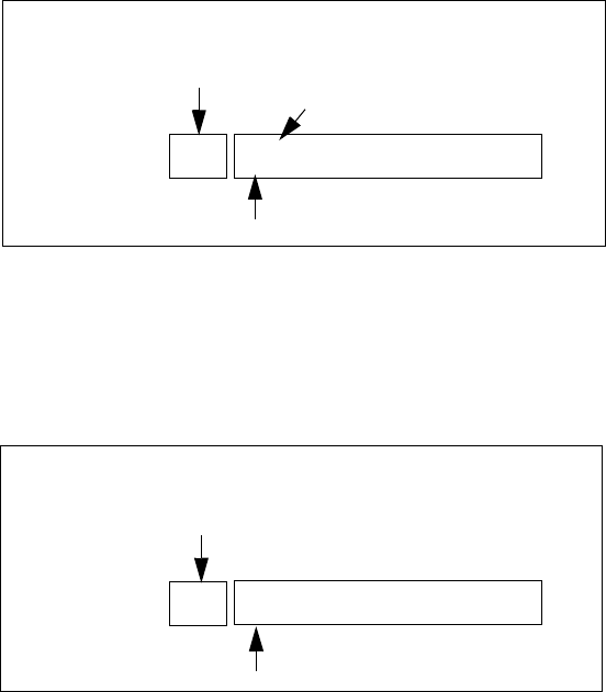
Visible Match Character
By inserting a special ASCII character directly before an entry field, the application
program distinguishes a “match field” from an entry field. For example, suppose an
angle bracket “>” is defined for visible match fields. Inserting “>” immediately
preceding the entry field identifies it as a match field, as illustrated below.
Part #> ___________
The range for this parameter – 0 to 127 – represents the decimal values of
ASCII characters. A value of 0 disables this feature. The ASCII decimal value
entered at the 9150 must coincide with the value set by the application program.
To use the Visible Match feature, the host computer preloads data into a match
entry field; the data is visible on the terminal screen. The preloaded data sent to a
terminal can consist of exact characters, special match characters or a combination
of the two. Refer to Table 6.2 on page 158 for match characters recognized by
Teklogix terminals.
If an entry does not match the preloaded data, the entry is displayed, the terminal
beeps, and the cursor moves to the first position in the match field. The operator can
either make another entry in the match field, or move the cursor to a new field.
Item No. I
AIAG Information From Host To Terminal Screen
@
AIAG Prefix (data)
AIAG Field Identifier

Chapter 6: Mini-Controller Configuration
3274/Telnet
158 Teklogix 9150 Wireless Gateway User Manual
When an entry (even one that doesn’t match the preloaded data) is made in a match
field, the entry is sent to the host as part of the terminal’s modified data during the
next transmission.
Table 6.2 Match Characters
Example:
Suppose you want to preload an entry field with a part number. If the part number is
known, you can preload the field with that part number. If more flexibility is needed,
and the part number always begins with two alphabetic characters followed by a
hyphen and four digits, the match string for the field would be: &&–#### .
Hidden Match Character
Unlike data in a “visible match” field, the preloaded data in a “hidden match” field
is not displayed at the terminal.
Note: Refer to “Visible Match Character” on page 157 for detailed information
about field matching.
The range for this parameter – 0 to 127 – represents the decimal values of ASCII
characters. A value of 0 disables this feature. The ASCII decimal value entered at
the 9150 must coincide with the value set by the application program.
Character Description
#Match a number.
&Match a letter (either case).
^Match an uppercase letter.
_Match a lowercase letter.
|Match an alphanumeric character.
"Match a letter, number or space.
?Match a punctuation character.
'Match any character.
:Match all character positions in the field with the preceding character.
;Match any remaining characters, but not necessarily the remainder of the field,
with the preceding character.
Teklogix 9150 Wireless Gateway User Manual 159
Chapter 6: Mini-Controller Configuration
3274/Telnet
Serial I/O
Serial I/O fields are special entry and fixed fields that accept input from and output
to a serial port. The application program distinguishes this field as Serial I/O by pre-
ceding the field with a special character.
If this character precedes a fixed field, the data will be sent to the terminal’s serial
port. If it precedes an entry field, the field accepts data from the terminal’s
serial port.
The range for this parameter – 0 to 127 – represents the decimal values of ASCII
characters. A value of 0 (zero) disables this feature.
Print Line
This parameter allows you to enter the starting line number of the print page in the
application screen. A value of 1 causes the display page to be printed; a value of 0
(zero) disables this feature.
Print Form Length
This parameter sets the printer’s form length in lines. The range is 0 to 24.
Barcode
Barcode-input-only fields are special entry fields that only accept input from a bar
code reader. The application program distinguishes an entry field as barcode-input-
only by preceding the field with a special character.
The range for this parameter – 0 to 127 – represents the decimal values of ASCII
characters. A value of 0 (zero) disables this feature.
Entry Line
This parameter contains the number of the first line displayed if there is no entry
field in the upper-left portion of the screen, and if an entry field is at or below
this line.
The Entry Line parameter allows an automatic offset within the host screen, so that
the area displayed by the terminal includes an entry field that would normally be out
of bounds. Normally, Teklogix terminals only display the upper-left corner of the
application screen because of their smaller display size.
Chapter 6: Mini-Controller Configuration
3274/Telnet
160 Teklogix 9150 Wireless Gateway User Manual
Field Overhead
This parameter contains the maximum number of characters allowed between two
fixed fields which still allows the 9150 to join them into one field.
Sometimes the 9150 will join two adjacent fixed fields and then send them as one
field. This reduces the overhead on the radio link.
For example, if two fields were 4 characters apart and this parameter was ‘5’, then
these fields would be joined into one.
Command Region
This parameter defines a region of the host screen which the 9150 will examine for
the presence of reserved commands.
The four numbers in the Command Region textboxes represent the row and column
addresses of the upper left corner and the lower right corner of the command region.
The first textbox of each pair contains the row number; the second contains the
column number. The range of row values is 0 to 24; column values are 0 to 80.
To define the last two lines of the host screen as the command region, for example,
enter the values 23, 1 and 24, 80.
Currently, the only command supported is ALARM (refer to page 151 for details on
this command). When the word “ALARM” is placed anywhere within the command
region, the 9150 will send a TESS beep command to the terminal.
Teklogix 9150 Wireless Gateway User Manual 161
Chapter 6: Mini-Controller Configuration
3274/Telnet
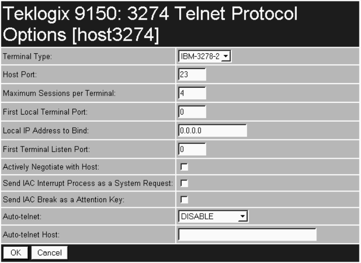
6.4.3.2 Protocol Options
This page differs depending on the type of emulation and protocol selected
in the General Host Options page (see page 148). The 9150 displays this version of
the Protocol Options page when you select the emulation/protocol combination of
3274/Telnet for this host.
Terminal Type
This parameter allows you to choose the type of terminal to be emulated by the 9150
for this host. At present there is only one choice of terminal for 3274/Telnet:
the IBM 3278-2.
Host Port
This parameter allows you to enter a host port value for the selected 3274/Telnet host
connection. The default value is 23.
Chapter 6: Mini-Controller Configuration
3274/Telnet
162 Teklogix 9150 Wireless Gateway User Manual
Maximum Sessions per Terminal
This parameter contains the maximum number of telnet sessions which are allowed
to originate from each terminal. The range is 0 to 127, with a default value of 4.
First Local Terminal Port
This parameter contains the local port number from which the first terminal will
connect on outbound telnet sessions. The default value is 0.
Local IP Address to Bind
This parameter contains the IP address of the network adaptor in the 9150 from
which the first terminal will connect on outbound telnet sessions.
First Terminal Listen Port
This parameter specifies the first port number at which the 9150 will listen for telnet
connection requests to the terminals. To enable this parameter, the value must be a
minimum of 1024. To disable the listen port, the value must be 0.
The default value is 0 (disabled).
Actively Negotiate with Host
If this parameter is enabled, the 9150 starts negotiations with the host during setup
of the telnet connection. Not recommended for most hosts.
Send IAC Interrupt Process as a System Request
If this parameter is enabled, the 9150 sends the IAC Interrupt Process request to the
host as a 3274 System Request.
Send IAC Break as an Attention Key
If this parameter is enabled, the 9150 sends the IAC Break request to the host as a
3274 Attention key.
Auto-telnet
This parameter enables you to disable or enable automatic connection of telnet
sessions from terminals to this host.
The choices provided are: Disable and Auto-telnet. The default value is Disable.

Teklogix 9150 Wireless Gateway User Manual 163
Chapter 6: Mini-Controller Configuration
3274/Telnet
When Auto-telnet is disabled, telnet sessions from the terminals to the host must be
initiated manually from the terminals.
When Auto-telnet is enabled, the 9150 initiates one telnet session from each termi-
nal whose terminal number is mapped to this host. Additional telnet sessions may be
initiated from each terminal to the host, but they must be initiated manually.
When Auto-telnet is enabled, the 9150 will automatically telnet to the host, both on
startup and when the session is closed.
Note: Auto-telnet sessions are only initiated for terminals which are “online”
(turned on and operating properly on the Teklogix RF network).
Auto-telnet Host
This parameter contains the host name or IP address for the host to which the 9150
connects Auto-telnet sessions.
Note: A host name placed in this textbox must be “resolvable” by the 9150:
the 9150 must be able to obtain an IP address for it. For example, the host
name may correspond to an entry in the 9150’s host table, or the 9150
may be able to query a domain-name server.
Any host name which can be used at the terminal’s TCP> prompt may be
used here.
Chapter 6: Mini-Controller Configuration
3274/Telnet
164 Teklogix 9150 Wireless Gateway User Manual
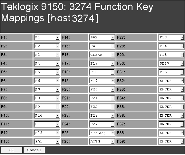
6.4.3.3 Function Key Mappings
This page differs depending on the type of emulation selected in the General Host
Options page. The 9150 displays this version of the Function Key Mapping page
when you select 3274 emulation for this host.
Function key n
The Function Key parameter allows you to select a code that will be sent to the host
when you press a function key on the terminal. Each function key may be chosen
from the same range of possible codes; however, each function key has a different
default code. The default values are shown on this page.
Teklogix 9150 Wireless Gateway User Manual 165
Chapter 6: Mini-Controller Configuration
5250/Telnet
6.4.4 5250/Telnet
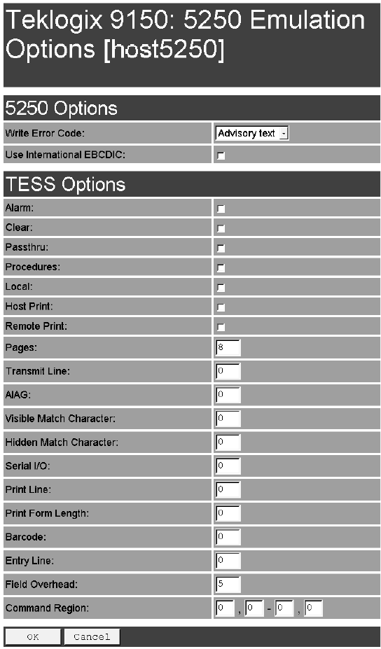
6.4.4.1 Emulation Options

Chapter 6: Mini-Controller Configuration
5250/Telnet
166 Teklogix 9150 Wireless Gateway User Manual
The 9150 displays this version of the Emulation Options page after you have
selected the 5250/Telnet emulation/protocol combination for this host connection.
With IBM 5250, or IBM 3274 emulation, the 9150 mini-controller converts the
application data stream from the host to TESS (Teklogix Screen Subsystem)
commands. Some of the parameters in this page govern the conversion of the host
screens to TESS.
Write Error Code
If advisory text is selected here, the 9150 sends error codes to the terminal screen as
advisory text, which is written at the bottom of the screen. If screen text is chosen,
the 9150 sends the error codes as regular screen text.
Use International EBCDIC
If this parameter is enabled, the 9150 will swap the positions of the ! and ] charac-
ters in the EBCDIC character table.
Alarm
If this parameter is enabled, terminals will beep when the word “ALARM”
(in capital letters) appears on the application screen, in the location specified by the
Command Region parameter (see page 175). The word “ALARM” should be a
display-only field.
Note: The Command Region parameter must be enabled for this
parameter to work.
Clear
If this parameter is enabled, the 9150 mini-controller creates an empty entry field
for an entry field that is filled with spaces.
Some host applications rely on the video attributes of displayed characters to high-
light fields, particularly entry fields. For example, the application screen may define
all entry fields with reverse video and fill the field with spaces. This is effective on
terminals that support reverse video, but on terminals that do not, it can make the
field invisible since it is made up entirely of spaces.

Teklogix 9150 Wireless Gateway User Manual 167
Chapter 6: Mini-Controller Configuration
5250/Telnet
By default, all empty entry fields displayed at the Teklogix terminal are highlighted
by the “entry character” chosen in the terminal’s configuration (not all Teklogix ter-
minals support video attributes). The Clear feature creates an empty entry field in
place of an entry field filled with spaces.
Note: This operation is only performed on screens received from the host. Data
sent to the host remains unaffected.
Passthru
If this parameter is enabled, the 9150 allows the host to send data directly to the RF
terminal’s serial port. This is most commonly used for printing.
Preparing Host Screens for Pass-Through
On the screen to be sent through the terminal serial port, the word “PASSTHRU”
(in capital letters) must appear on the first line, starting on the second column. The
actual data to be sent to the terminal may start anywhere below the first line.
With 5250 or 3274 emulations, attributes occupy a position in the screen buffer. An
attribute placed between column 2 and the end of the word “PASSTHRU” will push
all following characters one position to the right. Therefore, any required attributes
should occupy column 1 of the first line (just preceding the word “PASSTHRU”).
Example:
where @ is an attribute.
When the 9150 is finished sending the data to the terminal’s printer, it will send an
“ENTER” key to the host. The host must wait for the “ENTER” key before sending
any more screens (including other “PASSTHRU” screens) to this terminal.
Note: Refer to the appropriate Terminals User Manual for information about
setting parameters on the terminal for pass-through.
column: 1 2 3 4 5 6 7 8 9
line 1: @ P A S S T H R U @
line 2: @ P A R T : 1 2 3 4 5

Chapter 6: Mini-Controller Configuration
5250/Telnet
168 Teklogix 9150 Wireless Gateway User Manual
Procedures
If this parameter is enabled, the host may send TESS procedures through the 9150
to the terminals. A TESS procedure is a group of TESS commands that can be exe-
cuted by the TESS execute procedure command.
Local
If this parameter is enabled, the 9150 allows the host to provide pages to be loaded
as local TESS procedures in the terminals.
The local procedures are selected from a menu at the terminal. The terminals can
perform these procedures when they are offline. Later when the terminals are online,
they send the results of these functions to the host.
Note: The Procedures parameter must also be enabled for Local to work.
Host Print
When this parameter is enabled, the host can send extra data to the terminal’s
screens, and instruct the terminal to print it. This is in contrast to the Local Print fea-
ture, where the terminal makes the initial print request.
The text that is passed to the printer is formatted into the 24 x 80 application screen.
If the host can initiate the print operation, the text is printed. The 9150 identifies the
additional text as a print page by the presence of the word “PRINT” (in capital let-
ters) beginning in the 2nd column of line 13 on the 24 x 80 screen. The word
“PRINT” should be defined as display-only text.
The print page is positioned below the terminal’s display page (see Figure 6.6 on
page 169). The size of the print page is always the same as the terminal’s display
page (assuming that in the terminal’s configuration, the page length is less than 12
lines).
When Host Print is enabled, the 9150 passes the print page to the terminal after
receiving the application screen from the host.

Teklogix 9150 Wireless Gateway User Manual 169
Chapter 6: Mini-Controller Configuration
5250/Telnet
Figure 6.6 Application Screen With Print Page
Notes:
1. Unlike the Passthru option, when using Host Print no escape com-
mands can be sent to the printer.
2. Support for printing must be enabled at the terminal in its Printer
command under the TESS Features menu; refer to the appropriate
Terminals User Manual for more information.
Remote Print
When this parameter is enabled, the 9150 sends the print page to a terminal when-
ever the terminal requests it (by sending the “F17” function key from the terminal,
or the “PRINT” key on older terminals). The 9150 sends the function response back
to the host.
This is in contrast to Host Print, where the host makes the initial print request.
Note: Support for printing must be enabled at the terminal level. Refer to the
appropriate Terminals User Manual for more information.
1
2
3
4
5
6
7
8
9
10
11
12
13
14
15
16
17
18
19
20
21
22
23
24
Display Page (8 x 40)
Print Page (8 x 40)
PRINT

Chapter 6: Mini-Controller Configuration
5250/Telnet
170 Teklogix 9150 Wireless Gateway User Manual
Pages
This parameter determines the number of host screens (or pages) stored at
the terminal, to a maximum of 16.
The 9150 reduces data transmitted to the terminals by using the terminal’s capability
to store a page of data for each screen it displays. The 9150 maintains an image of
each page stored at the terminal. After receiving an application screen, the 9150 tries
to match the screen with a stored page.
If a similar page is already in the terminal’s memory, the 9150 instructs the terminal
to re-display its copy of the page; only the necessary changes are sent from the con-
troller. If no match is found, the complete page is sent to the terminal over the
radio link.
Note: There is a corresponding parameter on the terminal itself, and the actual
number of saved pages will be the smaller of the two values.
Transmit Line
When this feature is enabled, all modified data at the terminal will be automatically
transmitted when the operator enters data into a transmit-upon-entry field.
The value in this textbox specifies the line on the screen which is designated the
transmit line. The last entry field above or on the transmit line on the screen will be
identified as the transmit-upon-entry field. If any entry fields exist on lines below
the transmit line, no entry field will be designated as the transmit-upon-entry field.
A value of 0 (zero) disables this feature. A value of 24 will cause the last entry field
on each application screen to be defined as transmit-upon-entry.
AIAG
This parameter provides auto-locate and fill for input coming from bar code readers.
When bar code data is entered at a terminal, the terminal searches for “AIAG” fields
on the current page that can accept the bar code data. The data preloaded into the
“AIAG” field by the application program determines whether or not the bar code
data is accepted.
At the 9150 mini-controller, a decimal value of an ASCII character from 0 to 127
is set to match the “AIAG Field Identifier” set at the host. A value of 0 disables
this feature.

Teklogix 9150 Wireless Gateway User Manual 171
Chapter 6: Mini-Controller Configuration
5250/Telnet
The format of the preloaded data is as follows:
<mode> <AIAG prefix(data)>
The mode character used with the command allows for different operating modes to
suit various application operations. The automatic locate and fill operation applies
only to data received from a bar code reader. Descriptions of the modes and AIAG
prefix are listed in the table below. These modes are set at the host.
Table 6.3 Mode Functions And AIAG Prefix Description
Mode Function
0Display prefix, send prefix to host.
1Do not display prefix, send prefix to host.
2Display prefix, do not send prefix to host.
3Do not display prefix, do not send prefix to host.
+4 Add 4 to above values to cause transmit to host when all AIAG fields with 4
set are filled. Function 0 is “pressed” if there are any fields
with this bit set, and all fields with this bit set have been filled by
operator input.
+8 Add 8 to above values to allow overwrite of previously entered data.
+16 Add 16 to above values to indicate cursor position priority for search and fill.
AIAG Prefix
(data) The text to be matched in the AIAG field.
Chapter 6: Mini-Controller Configuration
5250/Telnet
172 Teklogix 9150 Wireless Gateway User Manual
Example:
The information in the sample screen below is defined at and sent from the host. It
includes the “AIAG Identifier” – the tag identifying this as an AIAG field – followed
by the mode, in this case Mode 0, and finally, the “AIAG Prefix” – I.
Figure 6.7 AIAG Field Sent From The Host
When the information arrives at the terminal screen, the appropriate AIAG field for
the scanned information is located using the “AIAG Identifier”. Because Mode 0
was set at the host, the “AIAG Prefix” – I – is displayed on the terminal screen, and
when this screen is completed, the prefix will be sent back to the host.
Figure 6.8 AIAG Field Sent To The Terminal
Visible Match Character
By inserting a special ASCII character directly before an entry field, the application
program distinguishes a “match field” from an entry field. For example, suppose an
angle bracket “>” is defined for visible match fields. Inserting “>” immediately
preceding the entry field identifies it as a match field, as illustrated below.
Part #> ___________
Item No. @0
AIAG Information From Host
AIAG Prefix (data)
Mode
AIAG Field Identifier
I
Item No. I
AIAG Information From Host To Terminal Screen
@
AIAG Prefix (data)
AIAG Field Identifier

Teklogix 9150 Wireless Gateway User Manual 173
Chapter 6: Mini-Controller Configuration
5250/Telnet
The range for this parameter – 0 to 127 – represents the decimal values of
ASCII characters. A value of 0 disables this feature. The ASCII decimal value
entered at the 9150 must coincide with the value set by the application program.
To use the Visible Match feature, the host computer preloads data into a match
entry field; the data is visible on the terminal screen. The preloaded data sent to a
terminal can consist of exact characters, special match characters or a combination
of the two. Refer to the table below for match characters recognized by
Teklogix terminals.
If an entry does not match the preloaded data, the entry is displayed, the terminal
beeps, and the cursor moves to the first position in the match field. The operator can
either make another entry in the match field, or move the cursor to a new field.
When an entry (even one that doesn’t match the preloaded data) is made in a match
field, the entry is sent to the host as part of the terminal’s modified data during the
next transmission.
Table 6.4 Match Characters
Character Description
#Match a number.
&Match a letter (either case).
^Match an uppercase letter.
_Match a lowercase letter.
|Match an alphanumeric character.
"Match a letter, number or space.
?Match a punctuation character.
'Match any character.
:Match all character positions in the field with the preceding character.
;Match any remaining characters, but not necessarily the remainder of the field,
with the preceding character.

Chapter 6: Mini-Controller Configuration
5250/Telnet
174 Teklogix 9150 Wireless Gateway User Manual
Example:
Suppose you want to preload an entry field with a part number. If the part number is
known, you can preload the field with that part number. If more flexibility is needed,
and the part number always begins with two alphabetic characters followed by a
hyphen and four digits, the match string for the field would be: &&–#### .
Hidden Match Character
Unlike data in a “visible match” field, the preloaded data in a “hidden match” field
is not displayed at the terminal.
Note: Refer to “Visible Match Character” on page 172 for detailed information
about field matching.
The range for this parameter – 0 to 127 – represents the decimal values of ASCII
characters. A value of 0 disables this feature. The ASCII decimal value entered at
the 9150 must coincide with the value set by the application program.
Serial I/O
Serial I/O fields are special entry and fixed fields that accept input from and output
to a serial port. The application program distinguishes this field as Serial I/O by pre-
ceding the field with a special character.
If this character precedes a fixed field, the data will be sent to the terminal’s serial
port. If it precedes an entry field, the field accepts data from the terminal’s
serial port.
The range for this parameter – 0 to 127 – represents the decimal values of ASCII
characters. A value of 0 (zero) disables this feature.
Print Line
This parameter allows you to enter the starting line number of the print page in the
application screen. A value of 1 causes the display page to be printed; a value of 0
(zero) disables this feature.
Print Form Length
This parameter sets the printer’s form length in lines. The range is 0 to 24.
Teklogix 9150 Wireless Gateway User Manual 175
Chapter 6: Mini-Controller Configuration
5250/Telnet
Barcode
Barcode-input-only fields are special entry fields that only accept input from a bar
code reader. The application program distinguishes an entry field as barcode-input-
only by preceding the field with a special character.
The range for this parameter – 0 to 127 – represents the decimal values of ASCII
characters. A value of 0 (zero) disables this feature.
Entry Line
This parameter contains the number of the first line displayed if there is no entry
field in the upper-left portion of the screen, and if an entry field is at or below
this line.
The Entry Line parameter allows an automatic offset within the host screen, so that
the area displayed by the terminal includes an entry field that would normally be out
of bounds. Normally, Teklogix terminals only display the upper-left corner of the
application screen because of their smaller display size.
Field Overhead
This parameter contains the maximum number of characters allowed between two
fixed fields which still allows the 9150 to join them into one field.
Sometimes the 9150 will join two adjacent fixed fields and then send them as one
field. This reduces the overhead on the radio link.
For example, if two fields were 4 characters apart and this parameter was ‘5’, then
these fields would be joined into one.
Command Region
This parameter defines a region of the host screen which the 9150 will examine for
the presence of reserved commands.
The four numbers in the Command Region textboxes represent the row and column
addresses of the upper left corner and the lower right corner of the command region.
The first textbox of each pair contains the row number; the second contains the
column number. The range of row values is 0 to 24; column values are 0 to 80.
To define the last two lines of the host screen as the command region, for example,
enter the values 23, 1 and 24, 80.
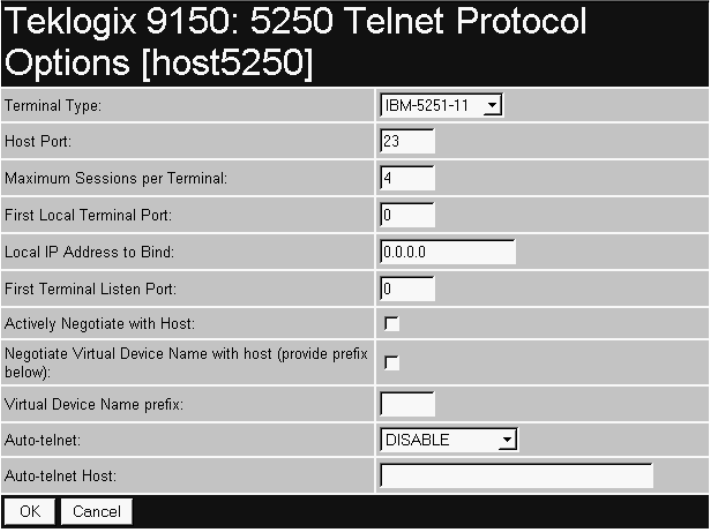
Chapter 6: Mini-Controller Configuration
5250/Telnet
176 Teklogix 9150 Wireless Gateway User Manual
Currently, the only command supported is ALARM (refer to page 166 for details on
this command). When the word “ALARM” is placed anywhere within the command
region, the 9150 will send a TESS beep command to the terminal.
6.4.4.2 Protocol Options
This page differs depending on the type of emulation and protocol selected in the
General Host Options page (see page 148). The 9150 displays this version of the
Protocol Options page when you select the emulation/protocol combination of
5250/Telnet for this host.
Terminal Type
This parameter allows you to choose the type of terminal to be emulated by the 9150
for this host. At present there are two choices of terminal for 5250/Telnet:
the IBM 5251-11 and IBM 5555-B01.
Teklogix 9150 Wireless Gateway User Manual 177
Chapter 6: Mini-Controller Configuration
5250/Telnet
Host Port
This parameter allows you to enter a host port value for the selected 5250/Telnet host
connection. The default value is 23.
Maximum Sessions per Terminal
This parameter contains the maximum number of telnet sessions which are allowed
to originate from each terminal. The range is 0 to 127, with a default value of 4.
First Local Terminal Port
This parameter contains the local port number from which the first terminal will
connect on outbound telnet sessions. The default value is 0.
Local IP Address to Bind
This parameter contains the IP address of the network adaptor from which the first
terminal will connect on outbound telnet sessions.
First Terminal Listen Port
This parameter specifies the first port number at which the 9150 will listen for telnet
connection requests to the terminals. To enable this parameter, the value must be a
minimum of 1024. To disable the listen port, the value must be 0.
The default value is 0 (disabled).
Actively Negotiate with Host
If this parameter is enabled, the 9150 starts negotiations with the host during setup
of the telnet connection. Not recommended for most hosts.
Negotiate Virtual Device Name with Host
If this parameter is enabled, the 9150 negotiates with the host to obtain a virtual
device name for the telnet connection.

Chapter 6: Mini-Controller Configuration
5250/Telnet
178 Teklogix 9150 Wireless Gateway User Manual
Virtual Device Name prefix
This parameter specifies a prefix for the automatically-generated virtual device
name. The device name on the host starts with the prefix, specifies the terminal (as a
number), and specifies a session number (as a letter). For example, if the virtual
device name prefix is TLX, the first session on terminal number 2 receives a virtual
device name of TLX0002A.
The prefix must use the SNA Type A character set, which includes uppercase letters
A-Z, numbers 0-9, and the special characters $, #, and @. Lowercase letters are
accepted and translated to uppercase characters. An SNA Type A character string
must not begin with a number.
Auto-telnet
This parameter enables you to disable or enable automatic connection of telnet
sessions from terminals to this host.
The choices provided are: Disable and Auto-telnet. The default value is Disable.
When Auto-telnet is disabled, telnet sessions from the terminals to the host must be
initiated manually from the terminals.
When Auto-telnet is enabled, the 9150 initiates one telnet session from each termi-
nal whose terminal number is mapped to this host. Additional telnet sessions may be
initiated from each terminal to the host, but they must be initiated manually.
When Auto-telnet is enabled, the 9150 will automatically telnet to the host, both on
startup and when the session is closed.
Note: Auto-telnet sessions are only initiated for terminals which are “online”
(turned on and operating properly on the Teklogix RF network).
Auto-telnet Host
This parameter contains the host name or IP address for the host to which the 9150
connects Auto-telnet sessions.
Note: A host name placed in this textbox must be “resolvable” by the 9150:
the 9150 must be able to obtain an IP address for it. For example, the host
name may correspond to an entry in the 9150’s host table, or the 9150
may be able to query a domain-name server. Any host name which can be
used at the terminal’s TCP> prompt may be used here.
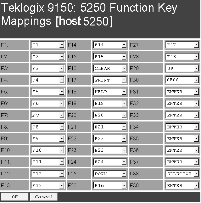
Teklogix 9150 Wireless Gateway User Manual 179
Chapter 6: Mini-Controller Configuration
5250/Telnet
6.4.4.3 Function Key Mappings
This page differs depending on the type of emulation selected in the General Host
Options page. The 9150 displays this version of the Function Key Mapping page
when you select 5250 emulation for this host.
Function key n
The Function Key parameter allows you to select a code that will be sent to the host
when you press a function key on the terminal. Each function key may be chosen
from the same range of possible codes; however, each function key has a different
default code. The default values are shown on this page.
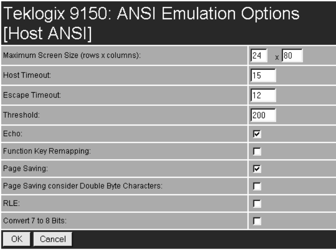
Chapter 6: Mini-Controller Configuration
ANSI/Telnet
180 Teklogix 9150 Wireless Gateway User Manual
6.4.5 ANSI/Telnet
6.4.5.1 Emulation Options
The 9150 displays this version of the Emulation Options page after you have
selected the ANSI/Telnet emulation/protocol combination for this host connection.
Maximum Screen Size
The Maximum Screen Size allows you to set the maximum required screen size in
terminals, by rows and columns. This feature ensures the optimal use of memory
when using the page saving option (see “Page Saving” on page 182).
The range is a minimum setting of 24 x 80 to a maximum setting of 60 x 132.
The default setting is 24 x 80.
Host Timeout
The Host Timeout is the interval (in ticks, or 60ths of a second) between bursts of
data received from the host. The range is 0 to 255, with a default value of 15.

Teklogix 9150 Wireless Gateway User Manual 181
Chapter 6: Mini-Controller Configuration
ANSI/Telnet
If the 9150 does not receive any characters from the host after this timeout has
elapsed, it assumes that the host has finished sending data and is waiting for user
input (in other words, it assumes that a screen of data has been completed).
Important: The Page Saving parameter (page 182) must be enabled in order
to change the value in the Host Timeout parameter.
Escape Timeout
The Escape Timeout is the length of time (in ticks, or 60ths of a second) that the
9150 will hold an “ESC” received from the host, and consider the next received byte
to be part of an escape sequence. The range is 0 to 255, with a default value of 12.
When this timeout has elapsed, the host will have to send another “ESC” character
to start an escape sequence.
Note: This is especially important when an ESC is at the end of a data packet.
Threshold
The Threshold is the minimum number of bytes of update data for the terminal
screen which must be received from the host before the 9150 will store the screen as
a new “saved page”. The range is 0 to 999, with a default value of 200.
Important: The Page Saving parameter (page 182) must be enabled in order
to change the value in the Threshold parameter.
Echo
If this parameter is enabled, the 9150 uses “Smart” Echo. This mode reduces the
amount of data sent to the terminal by decreasing the number of radio transmissions.
Ordinarily, when a character mode application is being used, each keystroke is sent
to the host in one transmission, and the character is echoed by the host in another
transmission. When “Smart” Echo is enabled, the 9150 will not send the host echo
to the terminals if it matches the data sent from the terminal. Thus, the number of
radio transmissions is reduced.
This mode also reduces or eliminates the delay between typing a character on the
keyboard and displaying the character echoed by the host. The maximum number of
characters waiting for echo is 25. Any additional characters will be sent to the host
but not displayed.

Chapter 6: Mini-Controller Configuration
ANSI/Telnet
182 Teklogix 9150 Wireless Gateway User Manual
Notes:
1. This parameter also determines whether an ANSI parameter query is
sent to the terminal.
2. “Smart” Echo also needs to be enabled at the terminal (refer to the
appropriate Terminals User Manual).
Function Key Remapping
If this parameter is enabled, the 9150 remaps the function keys for this host
connection as defined in the Function Key Remapping page (page 190).
Page Saving
If this parameter is enabled, the 9150 uses page saving, reducing data
transmitted to the terminals.
The 9150 maintains an image of each page stored at the terminal. After receiving an
application screen, the 9150 tries to match the screen with a stored page. If the page
is already in the terminal, the 9150 instructs the terminal to redisplay its stored copy
of the page; no data need be sent across the radio link for that page. If the 9150 finds
no match for the page, the complete page is sent to the terminal.
The default value is enabled.
Notes: When page saving is enabled, the number of saved pages is that which is
set on the terminal. Refer to the appropriate Terminals User Manual
for details.
If using double byte character sets, such as Chinese or Korean, please refer
to the Page Saving Consider Double Byte Character parameter, below.
Page Saving Consider Double Byte Character
When using double byte character sets such as Chinese or Korean, Page Saving (see
above) will allow a double byte character to be partially overwritten, which can lead
to a single byte of unprintable screen data or a new unintended character made up of
two halves of different characters. Also, the terminal may shift data on the screen to
truncate the bad data.

Teklogix 9150 Wireless Gateway User Manual 183
Chapter 6: Mini-Controller Configuration
ANSI/Telnet
When Page Saving Consider Double Byte Character is enabled, Page Saving will
replace any orphaned double byte character half with a space to prevent modified
characters and truncated data from being displayed on the terminal.
The default value is disabled.
Note: This option should only be used when using double byte character sets.
RLE
If this parameter is enabled, the 9150 uses run-length encoding (RLE) on the data it
sends across the radio link. RLE compresses repeated characters going from the host
to the terminal. If repeated characters are found in the data stream, the first one is
sent, followed by a short escape sequence (3 or 4 characters) which tells the terminal
how many times to repeat this character. In this way RLE compresses the data and
decreases the total amount of radio-link traffic.
Convert 7 to 8 Bits
If this parameter is enabled, the 9150 converts 7-bit control sequences to their 8-bit
equivalents in ANSI data streams going to the terminals. This replaces two-charac-
ter escape sequences with a single equivalent character, compressing the data.
6.4.5.2 Protocol Options
This page differs depending on the type of emulation and protocol selected in the
General Host Options page. When you select the emulation/protocol combination of
ANSI/Telnet for this host the 9150 displays the version of the Protocol Options
screen shown on page 184.
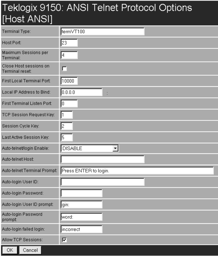
Chapter 6: Mini-Controller Configuration
ANSI/Telnet
184 Teklogix 9150 Wireless Gateway User Manual
1
Terminal Type
This parameter specifies the type of terminal to be emulated by the 9150. The char-
acters entered in the textbox can be any ASCII string acceptable to the host, with a
maximum of 32 characters. The default value is VT100.
Teklogix 9150 Wireless Gateway User Manual 185
Chapter 6: Mini-Controller Configuration
ANSI/Telnet
Host Port
This parameter specifies the value for the host port for the selected ANSI host con-
nection. The default value is 23.
Maximum Sessions per Terminal
This parameter contains the maximum number of telnet sessions which are allowed
to originate from each terminal. The range is 0 to 127, with a default value of 4.
Close Host Sessions on Terminal Reset
When this parameter is enabled, and a terminal reset message is received, the Host
session for that terminal number will be closed. The default value is disabled.
First Local Terminal Port
This parameter specifies the port number from which the 9150 attempts a telnet con-
nection for the first terminal. The default value is 0.
Additional telnet sessions are assigned higher port numbers.
Local IP Address to Bind
This parameter specifies the IP address of the 9150 interface that connects to this
host. It is used along with the local port numbers to create a unique socket for each
terminal session.
First Terminal Listen Port
This parameter specifies the first port number at which the 9150 will listen for telnet
connection requests to the terminals. To enable this parameter, the value must be a
minimum of 1024. To disable the listen port, the value must be 0.
The default value is 0 (disabled).
TCP Session Request Key
This parameter contains the decimal ASCII character code of the character which
will prompt the terminal to request a new ANSI terminal session. The range is 0 to
255, with a default value of 1.
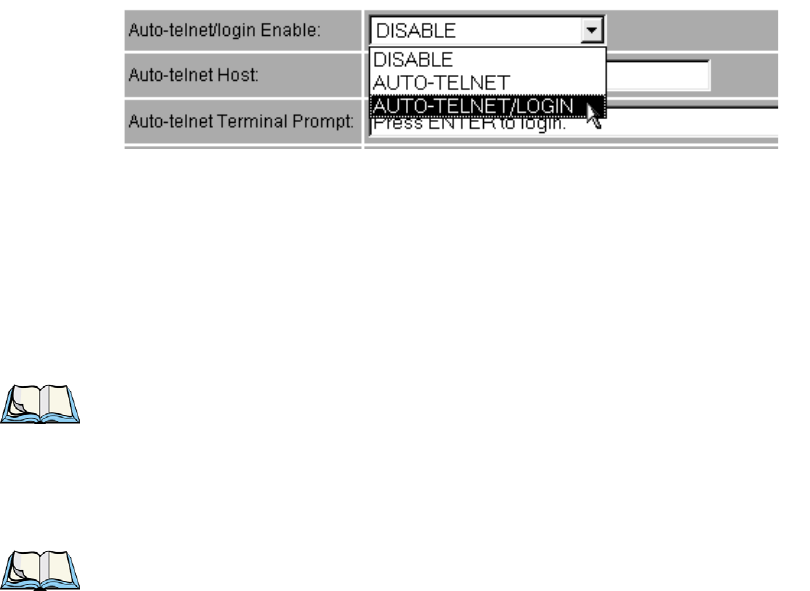
Chapter 6: Mini-Controller Configuration
ANSI/Telnet
186 Teklogix 9150 Wireless Gateway User Manual
Session Cycle Key
This parameter contains the decimal ASCII character code of the character which
will prompt the terminal to display the next ANSI terminal session. The range is 0 to
255, with a default value of 2.
Last Active Session Key
This parameter contains the decimal ASCII character code of the character which
will prompt the terminal to display the last ANSI terminal session. The range is 0 to
255, with a default value of 5.
Auto-telnet/login Enable
This parameter enables you to disable or enable automatic connection of telnet ses-
sions from terminals to this host. The choices provided are: DISABLE; AUTO-
TELNET; AUTO-TELNET/LOGIN.
The default value is DISABLE.
When Auto-telnet is disabled, telnet sessions from the terminals to the host must be
initiated manually from the terminals.
When Auto-telnet is enabled, the 9150 initiates one telnet session from each termi-
nal whose terminal number is mapped to this host. Additional telnet sessions may be
initiated from each terminal to the host, but they must be initiated manually.
Note: Auto-telnet sessions are only initiated for terminals which are “online”
(turned on and operating properly on the Teklogix RF network).
When Auto-telnet and Auto-login are enabled, the 9150 initiates one telnet session
from each terminal whose terminal number is mapped to this host. It then logs each
session in to the host using the User ID and Password provided in this page.
Note: The User ID and Password is identical for all Auto-telnet sessions
automatically logged in to this host.

Teklogix 9150 Wireless Gateway User Manual 187
Chapter 6: Mini-Controller Configuration
ANSI/Telnet
Auto-telnet Host
This parameter contains the host name or IP address for the host to which the 9150
connects Auto-telnet sessions.
Note: A host name placed in this textbox must be “resolvable” by the 9150:
the 9150 must be able to obtain an IP address for it. For example, the host
name may correspond to an entry in the 9150’s host table, or the 9150
may be able to query a domain-name server.
Any host name which can be used at the terminal’s TCP> prompt may be
used here.
Auto-telnet Terminal Prompt
This parameter contains the text presented to the user to request a login. The charac-
ters can be any ASCII string, or a numeric escape sequence presented in octal or
hexadecimal digits.
An octal escape sequence takes one of the forms: \0d, \0dd, or \0ddd, where each ‘d’
can be any digit from 0-7. If ‘ddd’ is greater than decimal 256, the code value of the
represented character will be the remainder of the decimal ddd/256.
A hexadecimal escape sequence takes one of the forms: \xh or xhh, where each ‘h’
can be any digit from 0-9, or any alpha value from a-f or A-F.
Note: \0 is considered a character, with a code value of 0.
The allowable value is a maximum of 60 characters in the line. The default is no
text, just press <ENTER> to login.
Auto-login User ID
This parameter contains the user ID presented by the 9150 to the host for the
Auto-login sessions. The characters can be any ASCII string acceptable to the host,
with a maximum of 32 characters.
Auto-login Password
This parameter contains the password presented by the 9150 to the host for the
Auto-login sessions. The characters can be any ASCII string acceptable to the host,
with a maximum of 32 characters.

Chapter 6: Mini-Controller Configuration
ANSI/Telnet
188 Teklogix 9150 Wireless Gateway User Manual
Auto-login User ID prompt
The 9150 compares the text in this textbox to the text presented to it by the host.
When they match, the 9150 assumes that the host has just sent its request for a user
name, and it sends the user ID specified in the Auto-Login User ID parameter to the
host. The characters can be any ASCII string, with a maximum of 32 characters.
The default text is gin:.
Note: The match string should be as short as possible, yet long enough to
uniquely identify the user-ID prompt. Do not include multi-part words
separated by space characters, since some hosts send out characters
other than space characters to present a space on the screen.
Auto-login Password prompt
The 9150 compares the text in this textbox to the text presented to it by the host.
When they match, the 9150 assumes that the host has just sent its request for a pass-
word, and it sends the password specified in the Auto-Login Password parameter to
the host. The characters can be any ASCII string, with a maximum of 32 characters.
The default text is word:.
Note: The match string should be as short as possible, yet long enough to
uniquely identify the password prompt. Do not include multi-part words
separated by space characters, since some hosts send out characters
other than space characters to present a space on the screen.
Auto-login failed login
The 9150 compares the text in this textbox to the text presented to it by the host.
When they match, the 9150 assumes that the host has just sent a string informing the
terminal of a failed login attempt. The 9150 then presents the Auto-telnet Terminal
Prompt on the terminal’s screen to request the user to login manually. The characters
can be any ASCII string, with a maximum of 32 characters. The default text
is incorrect.
Note: The match string should be as short as possible, yet long enough to
uniquely identify the failed-login prompt. Do not include multi-part words
separated by space characters, since some hosts send out characters
other than space characters to present a space on the screen.
Teklogix 9150 Wireless Gateway User Manual 189
Chapter 6: Mini-Controller Configuration
ANSI/Telnet
Allow TCP Sessions
When this parameter is enabled, the 9150 allows a terminal user to switch prompts
or sessions while at the prompt (either Auto-login or TCP). If Allow TCP Sessions is
disabled, all new sessions will open as Auto-login sessions.
Requesting sessions (normally <CTRL> a on the terminal) can be used at the
prompt level to change the type of prompt (if the other type of prompt is available).
Switching sessions at the prompt level is also available (on the terminal as
<CTRL> b [next session], or <CTRL> e [last session]). When switching sessions at
the prompt, the terminal state (not logged in) will be correctly adjusted to match that
of the switching in session.
The default value is enabled.
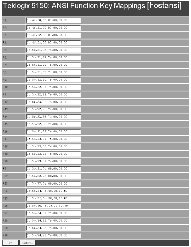
Chapter 6: Mini-Controller Configuration
ANSI/Telnet
190 Teklogix 9150 Wireless Gateway User Manual
6.4.5.3 Function Key Mappings
This page differs depending on the type of emulation selected in the General Host
Options page. The 9150 displays this version (page 191) of the Function Key
Mapping page after you have selected the ANSI/Telnet emulation/protocol combina-
tion for the host connection.

Teklogix 9150 Wireless Gateway User Manual 191
Chapter 6: Mini-Controller Configuration
RF Modem/Telnet
Function key n
The Function Key parameter allows you to select a code that will be sent to the host
when you press a function key on the terminal. Each function key may be chosen
from the same range of possible codes; however, each function key has a different
default code. The default values are shown on the screen above.
6.4.6 RF Modem/Telnet
RF Modem/Telnet is intended for a controller communicating with a Teklogix
Model 6040 RF Modem. The 6040 acts as a terminal on the Psion Teklogix network
to allow serial devices to communicate over that network (see the 6040 RF Modem
User Manual for details). Since the 6040 simply passes serial data through to con-
nected serial devices, there are no emulation or function key options. The 9150 dis-
plays this version of the Host Menu page after you have selected the RF
Modem/Telnet emulation/protocol combination for this host connection.
6.4.6.1 Emulation Options
These parameters are not applicable to the RF Modem emulation.
6.4.6.2 ANSI Telnet Protocol Options (RF Modem)
This page differs depending on the type of emulation and protocol selected in the
General Host Options page. The 9150 displays this version of the Protocol Options
page for the emulation/protocol combination RF Modem/Telnet for this host.

Chapter 6: Mini-Controller Configuration
802.IQ V2 Features Menu
192 Teklogix 9150 Wireless Gateway User Manual
First Terminal Listen Port
This parameter specifies the first port number at which the 9150 will listen for telnet
connection requests to the terminals. To enable this parameter, the value must be a
minimum of 1024. To disable the listen port, the value must be 10000. The default
value is 10000 (disabled).
6.4.6.3 Function Key Mappings
These parameters are not applicable to the RF Modem emulation.
6.5 802.IQ V2 Features Menu
This parameter accesses the 802.IQv2 sub-menu that enables the Psion Teklogix
proprietary 802.11b enhanced protocol, as described in “Psion Teklogix’ 802.IQ
Protocol” on page9. For detailed configuration information on 802.IQv1, please
refer to “802.IQ Version 1 Configuration Menu” on page64.
6.5.1 802.IQ Version 2 Configuration
802.IQ is a Psion Teklogix proprietary optimized protocol that enables terminals to
operate on a wireless LAN in a network that supports both TCP/IP and 802.IQ pro-
tocol simultaneously. 802.IQ protocol is available in two versions: 802.IQv1 and
802.IQv2. The 9150 can support both versions of the protocol at the same time (ter-
minals must use only one).
802.IQv1 protocol is a wireless LAN protocol that provides greater performance in
an 802.11b wireless network than is possible with TCP/IP. The 9150 bridges the
802.IQv1 wireless and TCP/IP wired networks.
802.IQv2 protocol is an enhanced version of the 802.IQv1 protocol that transports
packets over the UDP layer. It provides all the 802.IQv1 functionality, with the
added features of software upgrade capability over RF, the ability to add third-party
access points between controllers and terminals, and integration into the mapRF system,
if desired.
Important: 802.IQ should only be enabled on wired 9150s.
Do not configure 802.IQ on wired 9150s bridging networks, since
802.IQ beacons would be sent through the WDS link from one
network to the other (see “Wireless Distribution System (WDS)
Configuration” on page72).
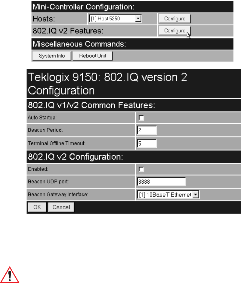
Teklogix 9150 Wireless Gateway User Manual 193
Chapter 6: Mini-Controller Configuration
802.IQ Version 2 Configuration
The 802.IQ Version 2 Configuration page is entered from the 802.IQ v2 Features
menu on the main web page, under Mini-Controller Configuration.
6.5.1.1 802.IQ v1/v2 Common Features
Auto Startup
This parameter enables ( √ ) 802.IQ immediately when the 9150 is rebooted. When
the 9150 is operating as a base station under a network controller or a 9150 mini-
controller, this parameter must be disabled. The default value is disabled.
Important: If Auto Startup is set incorrectly, terminals may not operate correctly.
Chapter 6: Mini-Controller Configuration
802.IQ Version 2 Configuration
194 Teklogix 9150 Wireless Gateway User Manual
Beacon Period
An 802.IQ beacon is a broadcast sent out to all 802.IQ-enabled terminals. The
beacon allows terminals to determine when they have roamed between base stations.
It enables a terminal to determine whether or not the base station or controller was
rebooted and, if so, how to recover. If the controller was rebooted, the terminal
closes all sessions and fully re-initializes. If the base station was rebooted, or if the
terminal moved to a different 9150, a warm initialize is done (no data will be lost).
The Beacon Period parameter acceptable value ranges from 1 to 20 seconds. The
default value is 2.
Terminal Offline Timeout
This parameter sets the time (in minutes) before the 802.IQ task on the 9150 will
send an offline message to the cellular master declaring the terminal offline.
The acceptable value ranges from 1 to 240. The default value is 5.
6.5.1.2 802.IQ v2 Configuration Submenu
Enabled
This parameter enables ( √ ) or disables the 802.IQv2 protocol.
The default value is disabled.
Beacon UDP Port
This parameter identifies the UDP port for beacon broadcasts. If more than one
802.IQv2 controller is on the network, the parameter must be changed to separate
the systems. The parameter must also match the corresponding parameter on the ter-
minal. The range of values is 5001 to 65535. The default value is 8888.
Beacon Gateway Interface
This is the interface on which the beacons are sent out.
The default is [1] 10BaseT Ethernet.

Teklogix 9150 Wireless Gateway User Manual 195
9100 MONITORING/DIAGNOSTICS 7
7.1 Fault Monitoring.........................197
7.1.1 Low Current Detection. . . . . . . . . . . . . . . 197
7.1.2 High Current Detection . . . . . . . . . . . . . . 197
7.1.3 Power Monitoring.................198
7.2 Diagnostics and Status Reporting ................198

Teklogix 9150 Wireless Gateway User Manual 197
Chapter 7: 9100 Monitoring/Diagnostics
Fault Monitoring
7.1 Fault Monitoring
Once power to a port is applied, the microcontroller enters a fault monitoring mode.
The diagnostic functions are:
• Low current condition
• High current condition
• Power Monitoring (conducted regardless of port state)
7.1.1 Low Current Detection
The microcontroller continuously checks ports in the “ON” state to determine if
each/any is in an under-current condition (this will typically happen when the Ether-
net cable is disconnected or some other fault occurs). This ensures that a powered
cable, when disconnected from a powered device, cannot be reconnected into some
other device, possibly causing damage to a non-compliant device.
If a Low Current condition is detected, then the power to the port is turned off. This
process is carried out for each of the four ports during fault monitoring. Following a
Low Current detection, the 9100 starts the discovery process again after a two-
second delay.
This fault is indicated by a slowly flashing yellow LED. After a two-second delay,
the 9100 will start the resistor detection again.
7.1.2 High Current Detection
Once a port is enabled, a sense voltage is measured periodically by the microcon-
troller to ensure that it remains less than the maximum allowed voltage, otherwise
an over-current fault occurs. A maximum continuous current of up to 350 mA is
allowed. To allow for inrush currents, which may occur when a powered device is
first connected (or the presence of a short or surge on the line), a hardware current-
limiting circuit ensures fail-safe output power control during the first 100mS follow-
ing port power-ON. Subsequently, the microcontroller will turn the port power OFF
immediately upon detection of an overcurrent condition.
Note: There is a five-second safety period before the 9100 begins resistor detec-
tion on a port that has triggered the overcurrent detection.

Chapter 7: 9100 Monitoring/Diagnostics
Power Monitoring
198 Teklogix 9150 Wireless Gateway User Manual
7.1.3 Power Monitoring
The 9100 power monitoring circuit constantly checks the operating condition of the
internal power supply. If the power goes out of range, all ports are turned off, and all
LEDs will be in Fast blink mode.
7.2 Diagnostics and Status Reporting
The 9100 PowerBaseT console port consists of a UART port on the microcontroller,
RS232 transceiver (U7) and a DB9 connector. Detailed information and the DB9
connector pinout is given on page B-4. The DB9 connector is used for the following
functions:
• Report Status Using a PC and HyperTerminal.
• Programming/Download Supports code updates by Field Service personnel.
The microcontroller is required to provide the following functions:
• Maintain port status Port off, Port on, fault
• Maintain port control Port enabled, Port disabled
• Report power consumption Monitor current flow using the current
sensing circuit.
The information in Figure 7.1 on page 199 is output on the console port every
second. The frequency at which this information is updated is adjustable via a
console command input. It can be set anywhere from never to 65,535 seconds, in
one-second increments. Serial port settings are 19,200 baud, no parity, 8 data bits, 1
stop bit.
Note: High and Low Current Detection:
A fault condition will be indicated by the LEDs and on the console until the
fault is cleared, either by the resistor detection for that port succeeding and
the port being switched ON, or disabling and re-enabling the port from
the console.

Teklogix 9150 Wireless Gateway User Manual 199
Chapter 7: 9100 Monitoring/Diagnostics
Diagnostics and Status Reporting
Figure 7.1 Annotated Console Information Screen
The possible states for any one port, as listed in Figure 7.1, are described below:
Disabled
Disabled in software via the console port. The port is inactive and will remain in
this state until it is enabled via the console, or the 9100 is reset. When the port is
activated, it transitions to the OFF state.
OFF
In this state the 9100 is constantly performing the auto-detect algorithm,
looking for 9150DCs connected to the port. When a 9150DC is found, the port
will transition to the ON state.
ON A 9150DC has been found, and DC power is switched on. The port is constantly
monitored for fault conditions. If everything remains within operating specifica-
tion, the port will remain in the ON state. Fault conditions may transition the
port to the Low Current fault or High Current fault state.
9100 PowerBaseT – Build1: D161o
Main supply: Good2
Port 1: Disabled current: 0 mA
Port 2: Off current: 0 mA
Port 3: On current3: 78 mA
Port 4: High Current4: current 0 mA
>5
1 Firmware build date.
2 Could also read “Bad”.
3 Current consumed by an active port.
4 Possible states: Disabled
Off
On
Low Current
High Current
5 Input prompt.
Chapter 7: 9100 Monitoring/Diagnostics
Diagnostics and Status Reporting
200 Teklogix 9150 Wireless Gateway User Manual
Low Current fault
A 9150DC that was previously being powered on this port has either been dis-
connected, or is not operating correctly. The 9100 will remove power from the
port and remain in this state for a minimum of two seconds before transitioning
to the OFF state. The port will continue to indicate the Low Current fault until it
either transitions to the ON state, or is disabled via the console.
High Current fault
A 9150DC that was previously being powered on this port is drawing too much
current from the 9100, or there is a short in the connecting cabling. The 9100
will remove power from the port and remain in this state for a minimum of five
seconds before transitioning to the OFF state. The port will continue to indicate
the High Current fault until it either transitions to the ON state, or is disabled via
the console.

Teklogix 9150 Wireless Gateway User Manual 201
SPECIFICATIONS 8
8.1 Specifications For The 9150 Wireless Gateway .........203
8.1.1 Physical Description . . . . . . . . . . . . . . . . 203
8.1.2 9150T Power Requirements . . . . . . . . . . . . 203
8.1.3 9150DC Power Requirements . . . . . . . . . . . 203
8.1.4 Processor And Memory . . . . . . . . . . . . . . 203
8.1.5 Environmental Requirements . . . . . . . . . . . 204
8.1.6 Network Interfaces. . . . . . . . . . . . . . . . . 204
8.1.7 PC Card Radios..................204
8.1.8 Approvals .....................205
8.2 Specifications For The 9100 PowerBaseT. ...........206
8.2.1 Physical Description . . . . . . . . . . . . . . . . 206
8.2.2 Power Requirements . . . . . . . . . . . . . . . . 206
8.2.3 Network Interface . . . . . . . . . . . . . . . . . 206
8.2.4 Electrical Safety Approvals . . . . . . . . . . . . 206
8.3 USI WaveLAN PC Card Regulatory Information. . . . . .207

Teklogix 9150 Wireless Gateway User Manual 203
Chapter 8: Specifications
Specifications For The 9150 Wireless Gateway
Note: Performance specifications are nominal and subject to change
without notice.
8.1 Specifications For The 9150 Wireless Gateway
8.1.1 Physical Description
Enclosure Bayer Makroblend EL-700 (PC/PET
blend), jet black in colour, texture to
MT-11030 or equivalent
Dimensions Nominal 36.3 x 26.2 x 7.4 cm (14.3 x 10.3 x 2.9 in.)
Maximum 36.8 x 26.7 x 7.6 cm (14.5 x 10.5 x 3.0 in.)
Weight Nominal 2.9 kg (6.5 lbs.)
Maximum 3.2 kg (7.0 lbs.)
8.1.2 9150T Power Requirements
Input voltage 100 - 240 V
Frequency 50/60 Hz
Current 1.0 A
Warning: To avoid electric shock, the power cord protective grounding
conductor must always be connected to ground.
8.1.3 9150DC Power Requirements
Input voltage 48 VDC nominal
Current 250 mA maximum
Warning: A ground wire, not exceeding 3 m in length, must be connected
between the ground screw (adjacent to the Auz.48V jack) and a
suitable earth ground bonding point.
8.1.4 Processor And Memory
9150T Wireless Gateway: Power PC 860T, 50 MHz Processor
9150DC Wireless Gateway: Power PC 860T, 50-60 MHz Processor
16 MB DRAM
2 MB Flash ROM

Chapter 8: Specifications
Environmental Requirements
204 Teklogix 9150 Wireless Gateway User Manual
8.1.5 Environmental Requirements
Operating Temperature 0°C to 50°C (32°F to 122°F)
Operating Rel. Humidity 10% to 90% (Non-condensing)
Storage Temperature -40°C to 70°C (-40°F to 158°F)
Dust and Rain IEC 529 IP42
8.1.6 Network Interfaces
9150DC Wireless Gateway
On-Board Ethernet 10BaseT/100BaseT (10/100Mb/s) card
Data rate is auto-sensed.
9150T Wireless Gateway
On-Board Ethernet 10BaseT/100BaseT (10/100Mb/s) card
Data rate is auto-sensed.
8.1.7 PC Card Radios
Important: For sites in Canada, USI WaveLAN 802.11 radios require a
radio licence, unless they are installed totally within a building.
(The user shall obtain this licence from Industry Canada.)
Teklogix 9150 Wireless Gateway User Manual 205
Chapter 8: Specifications
Approvals
USI WaveLAN IEEE 802.11 2.4 DSSS GHz (RA2020)*
Transmitter Power 36 mW
Frequency Range 2.4 to 2.4835 GHz
Data Rate 1, 2, 5.5, 11Mb/s
No. of Channels 11 (FCC)
4 (FR)
2 (SP)
13 (ETSI)
* For regulatory information concerning the USI WaveLAN PC Card, please
see page 207.
8.1.8 Approvals
FCC Part 15, subpart B, Class B
Electrical Safety: CSA/NRTL, TÜV, CB Scheme
ETS 300 086 ETS 300 328
CE Mark: EN 55022: 1998
EN 55024: 1998

Chapter 8: Specifications
Specifications For The 9100 PowerBaseT
206 Teklogix 9150 Wireless Gateway User Manual
8.2 Specifications For The 9100 PowerBaseT
8.2.1 Physical Description
Enclosure 12, 16, and 18 gauge steel with baked
enamel finish
Dimensions 48.3 x 18.1 x 4.3 cm (19 x 7.1 x 1.7 in.)
Weight 2.45 kg (5.4 1bs)
8.2.2 Power Requirements
Universal AC/DC power supply:
Input Voltage: 100 - 240 VAC 50-60Hz
Input Current 1.4 A - 0.6A
Output Voltage: 48 VDC +/- 2%
Output Power: 60 Watts
This power supply delivers 13 Watts per port for a total of 52 Watts. Power
supplied to each port is protected by over-voltage and current-limiting within the
power supply.
Warning: To avoid electric shock, the power cord protective grounding
conductor must always be connected to ground.
8.2.3 Network Interface
For each of Ports 1, 2, 3, and 4:
On-Board Ethernet The “Data” connector is patched to the
Ethernet backbone or switch/hub.
The “Data + 48V” connector is wired
directly to the 9150DC.
Note: The 9100 has no effect on the data passed through it. 48VDC is inserted on
the spare pins/conductors of the cable to the 9150DC.
8.2.4 Electrical Safety Approvals
CSA/NRTL/C and CB certificate
Chapter 8: Specifications
WaveLAN PC Card Regulatory Information
208 Teklogix 9150 Wireless Gateway User Manual
Interference Statement
This equipment has been tested and found to comply with the limits for a Class B
digital device, pursuant to Part 15 of the FCC Rules. These limits are designed to
provide reasonable protection against harmful interference in a residential
installation.
This equipment generates, uses, and can radiate radio frequency energy. If not
installed and used in accordance with the instructions, it may cause harmful interfer-
ence to radio communications. However, there is no guarantee that interference will
not occur in a particular installation.
If this equipment does cause harmful interference to radio or television reception,
which can be determined by turning the equipment off and on, the user is encour-
aged to try and correct the interference by one or more of the following measures:
• Reorient or relocate the receiving antenna.
• Increase the distance between the equipment and the receiver.
• Connect the equipment to an outlet on a circuit different from that to which
the receiver is connected.
• Consult the dealer or an experienced radio/TV technician for help.
Psion Teklogix Inc. is not responsible for any radio or television interfer-
ence caused by unauthorized modification.
The correction of interference caused by such unauthorized modification, substitu-
tion or attachment will be the responsibility of the user.
For country-specific approvals, please consult the flyer “Radio Certification Infor-
mation” that is included with the 9150 Wireless Gateway.

Teklogix 9150 Wireless Gateway User Manual A-1
APPENDIX A
SUPPORT SERVICES AND WORLDWIDE OFFICES
A.1 Support Services
Psion Teklogix provides a complete range of product support services to its
customers worldwide. These services include post-installation technical support and
product repairs.
A.1.1 Canada and U.S.A: Technical Support and Repair Services
In Canada and the U.S.A. these services can be accessed through the Psion Teklogix
Helpdesk. The Helpdesk coordinates repairs, helps you troubleshoot problems over
the phone, and arranges for technicians or engineers to come to your site.
Canadian and U.S. customers may receive access to technical support services,
ranging from phone support to emergency on-site system support, by calling the
toll-free number below, or via our secure web site.
Note: Customers calling the toll-free number should have their Psion Teklogix
customer number or trouble ticket number available.
Voice: 1 800 387-8898
Fax: 1 905 812-6304
Web Site: http://service.psionteklogix.com
A.1.2 International Support
For technical support outside of Canada or the U.S.A., please contact your local
Psion Teklogix office. See page A-3 for a listing of worldwide offices.
Teklogix 9150 Wireless Gateway User Manual A-3
A.2 WORLDWIDE OFFICES
COMPANY HEADQUARTERS
AND CANADIAN SERVICE CENTRE
Psion Teklogix Inc.
2100 Meadowvale Boulevard
Mississauga
Ontario
Canada L5N 7J9
Tel: +1 905 813 9900
Fax: +1 905 812 6300
E-mail: salescdn@psion.com
INTERNATIONAL SUBSIDIARIES
Psion Teklogix GmbH
Jakob Kaiser Straße 3
D-47877 Willich Münchheide
Deutschland
Tel: +49 2154 9282 0
Fax: +49 2154 9282 59
E-mail: info@teklogix.de
Psion Teklogix S.A.
La Duranne
135 Rue Rene Descartes
BP 421000
13591 Aix-En-Provence
Cedex 3; France
Tel: +33 (0) 4.42.908.809
Fax: +33 (0) 4.42.908.888
E-mail: tekeuro@psion.com
Psion Teklogix LTD.
3, Lancaster Court
Coronation Road High Wycombe
Bucks HP123TD, England
Tel: +44 1494 450666
Fax: +44 1494 450155
WWW: www.teklogix.co.uk
E-mail: tekuk@psion.com
Psion Teklogix AB
Stora Badhusgatan 18-20
411 21 Göthenburg, Sweden
Tel: +46 31 13 15 50
Fax: +46 31 13 57 80
E-mail: info@teklogix.se
NORTH AMERICAN HEADQUARTERS
AND U.S. SERVICE CENTRE
Psion Teklogix Corp.
1810 Airport Exchange Boulevard
Suite 500
Erlanger, Kentucky
USA 41018
Tel: +1 859 371 6006
Fax: +1 859 371 6422
E-mail: salesusa@psion.com
Psion Teklogix Finland
Metsänneidonkuja 8
02130 Espoo
Finland
Tel: +358 9 4307 8390
Fax: +358 9 4307 8395
E-mail: tekeuro@psion.com
Psion Teklogix Danmark
Vesterballevej 4-6
7000 Fredericia
Danmark
Tel: +45 76 24 0133
Fax: +45 75 94 4679
E-mail: tedk@psion.com
Psion Teklogix Italia S.r.I
Via Galilei, 47
20092 Cinisello Balsamo
Milan, Italy
Tel: +39 2 6604 5410
Fax: +39 2 6604 5412
E-mail: tkxitalia@psion.com
Psion Teklogix Inc. (Singapore)
583 Orchard Road
# 15-01 Forum
Singapore 238884
Tel: +65 735 8108
Fax: +65 733 5990
E-mail: intl@psion.com
Psion Teklogix de Mexico, S.A. de C.V.
Sierra Mojada 626, 2º Piso
Col. Lomas Barrilaco, C.P. 11010
Mexico, D.F., Mexico
Tel: +52 5 327 1124
Fax: +52 5 327 1123
E-mail: salesusa@psion.com
Psion Teklogix do Brasil, Ltda.
Al. Casa Branca, 851 - conj. 101 e 102
São Paulo - SP - 01408-001
Brasil
Tel: +55 11 3064 0868
Fax: +55 11 3068 8198
WWW: www.teklogixbrasil.com.br
E-mail: tekbr@psion.com
Chile Psion Teklogix International Inc.
Avenida Vitacura 2909, Oficina 703
Las Condes
Santiago, Chile
Tel: +56 2 334 9344
Fax: +56 2 233 3868
E-mail: ventas@psion.com
Psion Teklogix de Argentina, S.A.
Avenida Moreau de Justo 1180
Piso 1, Oficina C-105
Buenos Aires 1107
Argentina
Tel: +54 11 4343 0193
Fax: +54 11 4343 6310
E-mail: tekar@psion.com
A-4Teklogix 9150 Wireless Gateway User Manual
Psion Teklogix España, S.L.
Cityparc Ronda de Dalt
Ctra. Hospitalet 147-149
Edificio Atenas 2° 3ª
08940 Cornellà de Llobregat (Barcelona)
España
Tel: +34 9 3475 0220
Fax: +34 9 3475 0230
E-mail: teklogix@apdo.com
Psion Teklogix Africa
Postnet Suite 39, Private Bag x11
Halfwayhouse, 1685 Ground Floor East
Waterfall Edge Phase 2, Waterfall Park
Bekker Road MIDRAND 1685
South Africa
Tel: +27 11 805 7440/1/2
Fax: +27 11 805 7444
Psion Teklogix Systems India Pvt. Ltd.
M-74, 1st Floor, “M” Block Market
Greater Kailash-Il
New Delhi - 110048
India
Tel: +91 11 621 9257
Fax: +91 11 621 9076
E-mail: tekind@psion.com
Psion Teklogix B.V.
Venrayseweg 57,
5928 NZ Venlo
Nederlands
Tel: +31 77 32400 44
Fax: +31 77 32400 53
Psion Teklogix Taiwan Co., Ltd.
15FL-5, No. 366 Boai 2nd Road,
Tzuo Ying District, KAOHSIUNG 813
Taiwan, R.O.C.
Tel: +886 7 558 2028
Fax: +886 7 558 3328
E-mail: jerry.chen@teklogix.com
A.3 WORLDWIDE WEB
www.psionteklogix.com

Teklogix 9150 Wireless Gateway User Manual B-1
APPENDIX B
PORT PINOUTS AND CABLE DIAGRAMS
B.1 Console Port
* always pulled high
Pin No. Name Function Direction
3 TD Transmit Data Out
2 RD Receive Data In
5 SG Signal Ground –
4* DTR Data Terminal Ready Out
7* RTS Request to Send Out
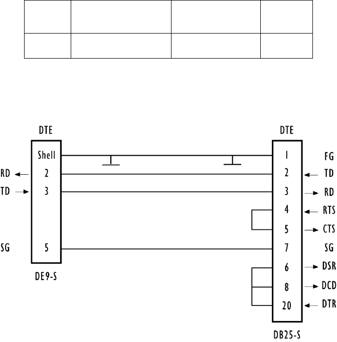
Appendix B: Port Pinouts And Cable Diagrams
Serial Cable Descriptions
B-2 Teklogix 9150 Wireless Gateway User Manual
B.2 Serial Cable Descriptions
Console Port Cable No. 19387
Cable No. Function Connection Standard
Length
19387 9150 to Console Direct 6 feet
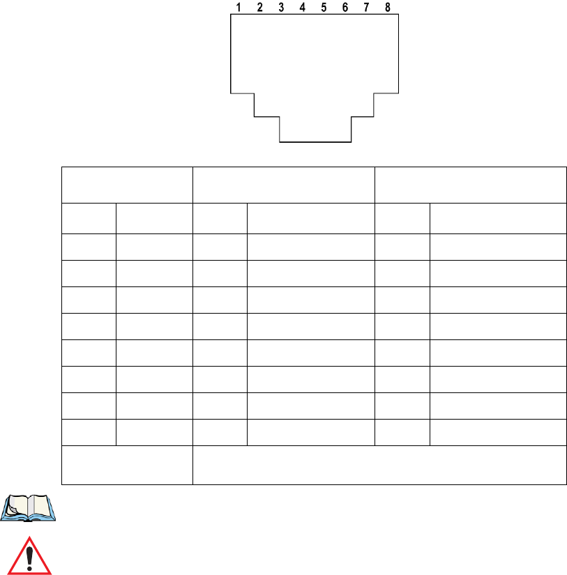
Teklogix 9150 Wireless Gateway User Manual B-3
Appendix B: Port Pinouts And Cable Diagrams
RJ-45 Connector Pinouts (10BaseT/100BaseT Ethernet)
B.3 RJ-45 Connector Pinouts (10BaseT/100BaseT Ethernet)
Note: Usually, a straight-through connection is needed to connect Twisted-Pair
(10BaseT or 100BaseT) to the hub.
Important: For Main Logic Board (MLB) P/N 30183-301 Rev F only: When
connecting the RJ-45 Ethernet cable to the 9150T (AC power ver-
sion), ensure that the snap-on ferrite for cables (P/N 97776) is
placed on the cable as closely as possible to the RJ-45 jack. To
determine which version of the MLB is resident in your 9150,
please contact Psion Teklogix Support Services (see page A-1).
9150T 9150DC* 9100 PowerBaseT
Contact Signal Contact Signal Contact Signal
1 TD+ 1 TD+ 1 TD+
2TD
–2TD
–2TD
–
3 RD+ 3 RD+ 3 RD+
4 Not used 4 +48 VDC In 4 +48 VDC Out
5 Not used 5 +48 VDC In 5 +48 VDC Out
6RD
–6RD
–6RD
–
7 Not used 7 48 VDC Return In 7 48 VDC Return Out
8 Not used 8 48 VDC Return In 8 48 VDC Return Out
* The 9150DC can also accept 48 VDC power bias on the data line
pairs (1,2) and (3,6) from such systems providing power over Ethernet.

Appendix B: Port Pinouts And Cable Diagrams
9100 PowerBaseT Console Port Pinout
B-4 Teklogix 9150 Wireless Gateway User Manual
B.4 9100 PowerBaseT Console Port Pinout
The 9100 PowerBaseT console port consists of a UART port on the microcontroller,
RS232 transceiver (U7) and a DB9 connector (J16) pins 2 (RXD), 3 (TXD) and 5
(GND). The same connector (J16) is used to connect the Programmer to the 9100
PowerBaseT.
Note: Programming equipment for Field Service use:
Programmer (P/N 21297)
Cable, Programmer to 9100 (P/N 98109)
Cable, Programmer to PC (P/N 19687)
The DB9 connector pins 1, 4, 5, 6, and 9 are used during the programming/down-
load phase. The DB9 connector pinout is given in the table on page B-5, with the
Function field describing the function performed by each pin (Programming/Down-
load or Console).
The DB9 connector is used for the following functions:
• Report Status Using a PC and HyperTerminal.
• Programming/Download Supports code updates by Field Service personnel.
The microcontroller features a full duplex (separate receive and transmit registers)
UART with baud generator, 8 or 9 data bits, noise filtering, overrun detection,
framing error detection, and interrupts. The transceiver is 5 V powered with two
drivers and two receivers with extra protection against ESD.

Teklogix 9150 Wireless Gateway User Manual B-5
Appendix B: Port Pinouts And Cable Diagrams
9100 PowerBaseT Console Port Pinout
9100 PowerBaseT Console Port Pinout Table
PIN# Signal Name Function Description
1 PROGRAM_DATA_IN Programming/
Download Data Input from the
programmer
2 RXD Console Serial Data Input
3 TXD Console Serial Data Output
4 PROGRAM_DATA_OUT Programming/
Download Data Output to the
programmer
5 GND Console and
Programming/
Download Ground
6 PROGRAM_CLOCK Programming/
Download Clock Input from the
programmer
7NC
8NC
9 PROGRAM_EN Programming/
Download Programming enable

Teklogix 9150 Wireless Gateway User Manual C-1
APPENDIX C
MAC BRIDGE PROTOCOL FILTERS AND OUIS
C.1 Ethernet II Types (RFC 1700)
C.1.1 Listing by Description
DESCRIPTION TYPE (HEX VALUES)
3Com Corporation 0x6010-0x6014
3Com(Bridge) loop detect 0x9003
3Com(Bridge) TCP-IP Sys 0x9002
3Com(Bridge) XNS Sys Mgmt 0x9001
Advanced Encryption System 0x823E-0x8240
Aeonic Systems 0x8036
Allen-Bradley 0x80E0-0x80E3
Alpha Micro 0x814A
Apollo Computer 0x80F7
Apollo Computers 0x8019
Appletalk 0x809B
AppleTalk AARP (Kinetics) 0x80F3
Applitek Corporation 0x80C7
Apricot Computers 0x81CC-0x81D5
ARAI Bunkichi 0x81A4
ARP 0x0806
Artisoft 0x81D6-0x81DD
Ascom Banking Systems 0x8221-0x8222

Appendix C: MAC Bridge Protocol Filters and OUIs
Ethernet II Types (RFC 1700)
C-2 Teklogix 9150 Wireless Gateway User Manual
AT&T 0x8008
AT&T 0x8046
AT&T 0x8047
AT&T 0x8069
Athena Programming 0x827F-0x8282
ATOMIC 0x86DF
Autophon 0x806A
Banyan Systems 0x0BAD
Banyan Systems 0x80C4
Banyan Systems 0x80C5
BBN Simnet 0x5208
BBN VITAL-LanBridge cache 0xFF00
Berkeley Trailer encap/IP 0x1001-0x100F
Berkeley Trailer nego 0x1000
BIIN 0x814D
BIIN 0x814E
Bridge Communications 0x8132-0x8136
Cabletron 0x7034
Chaosnet 0x0804
Charles River Data System 0x8164-0x8166
Charles River Data System 0x8263-0x826A
ComDesign 0x806C
Computer Network Tech 0x869E-0x86A1
Computer Protocol Pty Ltd. 0x815C-0x815E
Computgraphic Corp. 0x806D
Comsat Labs 0x81F0-0x81F2
DESCRIPTION TYPE (HEX VALUES)

Teklogix 9150 Wireless Gateway User Manual C-3
Appendix C: MAC Bridge Protocol Filters and OUIs
Ethernet II Types (RFC 1700)
Counterpoint Computers 0x8062
Counterpoint Computers 0x8081-0x8083
Cronus Direct 0x8004
Cronus VLN 0x8003
Dansk Data Elektronik 0x807B
Datability 0x809C-0x809E
Datability 0x80E4-0x80F0
DCA Data Exchange Cluster 0x80C0-0x80C3
DEC Customer Protocol 0x6006
DEC DECNET Phase IV Route 0x6003
DEC Diagnostic Protocol 0x6005
DEC Ethernet Encryption 0x803D
DEC LAN Traffic Monitor 0x803F
DEC LANBridge 0x8038
DEC LAT 0x6004
DEC LAVC, SCA 0x6007
DEC MOP Dump/Load 0x6001
DEC MOP Remote Console 0x6002
DEC Unassigned 0x6008-0x6009
DEC Unassigned 0x8039-0x803C
DEC Unassigned 0x803E
DEC Unassigned 0x8040-0x8042
DEC Unassigned (Exp.) 0x6000
Delta Controls 0x86DE
DLOG 0x0660
DLOG 0x0661
DESCRIPTION TYPE (HEX VALUES)

Appendix C: MAC Bridge Protocol Filters and OUIs
Ethernet II Types (RFC 1700)
C-4 Teklogix 9150 Wireless Gateway User Manual
ECMA Internet 0x0803
Evans & Sutherland 0x805D
Excelan 0x8010
ExperData 0x8049
Gateway Communications 0x86A3-0x86AC
General Dynamics 0x8068
Harris Corporation 0x80CD-0x80CE
Hayes Microcomputers 0x8130
HP Probe 0x8005
IBM SNA Service on Ether 0x80D5
Idea Courier 0x8694-0x869D
Inst Ind Info Tech 0x829A-0x829B
Integrated Solutions TRFS 0x80DE-0x80DF
Intergraph Corporation 0x80C8-0x80CC
Internet IP (IPv4) 0x0800
Invisible Software 0x8A96-0x8A97
ISC Bunker Ramo 0xFF00-0xFF0F
Kinetics 0x80F4-0x80F5
KTI 0x8139-0x813D
Landis & Gyr Powers 0x86E0-0x86EF
Landmark Graphics Corp. 0x806E-0x8077
Little Machines 0x8060
Logicraft 0x8148
Loopback 0x9000
LRT 0x7020-0x7029
Matra 0x807A
DESCRIPTION TYPE (HEX VALUES)

Teklogix 9150 Wireless Gateway User Manual C-5
Appendix C: MAC Bridge Protocol Filters and OUIs
Ethernet II Types (RFC 1700)
Merit Internodal 0x807C
Motorola 0x8700-0x8710
Motorola Computer 0x818D
NBS Internet 0x0802
Nestar 0x8006
Network Computing Devices 0x8149
Nixdorf Computers 0x80A3
Novell, Inc. 0x8137-0x8138
Pacer Software 0x80C6
PCS Basic Block Protocol 0x4242
Planning Research Corp. 0x8044
Polygon 0x81E6-0x81EF
Proteon 0x7030
Protocol Engines 0x817D-0x818C
PUP Addr Trans 0x0A01
Qualcomm 0x8151-0x8153
Qualcomm 0x819A-0x81A3
Quantum Software 0x8203-0x8205
RAD Network Devices 0x81A5-0x81AE
Rational Corp 0x8150
Retix 0x80F2
Reverse ARP 0x8035
Rosemount Corporation 0x80D3-0x80D4
SAIC 0x81F3-0x81F5
SECTRA 0x86DB
SGI bounce server 0x8016
DESCRIPTION TYPE (HEX VALUES)

Appendix C: MAC Bridge Protocol Filters and OUIs
Ethernet II Types (RFC 1700)
C-6 Teklogix 9150 Wireless Gateway User Manual
SGI diagnostics 0x8013
SGI network games 0x8014
SGI reserved 0x8015
Siemens Gammasonics Inc. 0x80A4-0x80B3
SNMP 0x814C
Spider Systems Ltd. 0x809F
Stanford V Kernel exp. 0x805B
Stanford V Kernel prod. 0x805C
Symbolics Private 0x081C
Symbolics Private 0x8107-0x8109
Taurus Controls 0x829C-0x82AB
Taylor Instrument 0x80CF-0x80D2
Technically Elite Concept 0x814F
Tigan, Inc. 0x802F
Tymshare 0x802E
Ungermann-Bass dia/loop 0x7002
Ungermann-Bass download 0x7000
Ungermann-Bass net debugr 0x0900
Univ. of Mass. @ Amherst 0x8065
Univ. of Mass. @ Amherst 0x8066
Valid Systems 0x1600
Varian Associates 0x80DD
Veeco Integrated Auto. 0x8067
VG Analytical 0x81F6-0x81F8
VG Laboratory Systems 0x8131
Vitalink Communications 0x807D-0x807F
DESCRIPTION TYPE (HEX VALUES)

Teklogix 9150 Wireless Gateway User Manual C-7
Appendix C: MAC Bridge Protocol Filters and OUIs
Ethernet II Types (RFC 1700)
Vitalink TransLAN III 0x8080
Walker Richer & Quinn 0x82AC-0x8693
Wellfleet Communications 0x80FF-0x8103
X.25 Level 3 0x0805
X.75 Internet 0x0801
Xerox IEEE802.3 PUP 0x0A00
XEROX NS IDP 0x0600
XNS Compatibility 0x0807
Xyplex 0x0888-0x088A
Xyplex 0x81B7-0x81B9
DESCRIPTION TYPE (HEX VALUES)

Appendix C: MAC Bridge Protocol Filters and OUIs
Ethernet II Types (RFC 1700)
C-8 Teklogix 9150 Wireless Gateway User Manual
C.1.2 Listing By Type (Hexadecimal)
TYPE (HEX VALUES) DESCRIPTION
0x0600 XEROX NS IDP
0x0660 DLOG
0x0661 DLOG
0x0800 Internet IP (IPv4)
0x0801 X.75 Internet
0x0802 NBS Internet
0x0803 ECMA Internet
0x0804 Chaosnet
0x0805 X.25 Level 3
0x0806 ARP
0x0807 XNS Compatibility
0x081C Symbolics Private
0x0888-0x088A Xyplex
0x0900 Ungermann-Bass net debugr
0x0A00 Xerox IEEE802.3 PUP
0x0A01 PUP Addr Trans
0x0BAD Banyan Systems
0x1000 Berkeley Trailer nego
0x1001-0x100F Berkeley Trailer encap/IP
0x1600 Valid Systems
0x4242 PCS Basic Block Protocol
0x5208 BBN Simnet
0x6000 DEC Unassigned (Exp.)
0x6001 DEC MOP Dump/Load
0x6002 DEC MOP Remote Console

Teklogix 9150 Wireless Gateway User Manual C-9
Appendix C: MAC Bridge Protocol Filters and OUIs
Ethernet II Types (RFC 1700)
0x6003 DEC DECNET Phase IV Route
0x6004 DEC LAT
0x6005 DEC Diagnostic Protocol
0x6006 DEC Customer Protocol
0x6007 DEC LAVC, SCA
0x6008- DEC Unassigned
0x6009 DEC Unassigned
0x6010-0x6014 3Com Corporation
0x7000 Ungermann-Bass download
0x7002 Ungermann-Bass dia/loop
0x7020-0x7029 LRT
0x7030 Proteon
0x7034 Cabletron
0x8003 Cronus VLN
0x8004 Cronus Direct
0x8005 HP Probe
0x8006 Nestar
0x8008 AT&T
0x8010 Excelan
0x8013 SGI diagnostics
0x8014 SGI network games
0x8015 SGI reserved
0x8016 SGI bounce server
0x8019 Apollo Computers
0x802E Tymshare
0x802F Tigan, Inc.
TYPE (HEX VALUES) DESCRIPTION

Appendix C: MAC Bridge Protocol Filters and OUIs
Ethernet II Types (RFC 1700)
C-10 Teklogix 9150 Wireless Gateway User Manual
0x8035 Reverse ARP
0x8036 Aeonic Systems
0x8038 DEC LANBridge
0x8039-0x803C DEC Unassigned
0x803D DEC Ethernet Encryption
0x803E DEC Unassigned
0x803F DEC LAN Traffic Monitor
0x8040-0x8042 DEC Unassigned
0x8044 Planning Research Corp.
0x8046 AT&T
0x8047 AT&T
0x8049 ExperData
0x805B Stanford V Kernel exp.
0x805C Stanford V Kernel prod.
0x805D Evans & Sutherland
0x8060 Little Machines
0x8062 Counterpoint Computers
0x8065 Univ. of Mass. @ Amherst
0x8066 Univ. of Mass. @ Amherst
0x8067 Veeco Integrated Auto.
0x8068 General Dynamics
0x8069 AT&T
0x806A Autophon
0x806C ComDesign
0x806D Computgraphic Corp.
0x806E-0x8077 Landmark Graphics Corp.
TYPE (HEX VALUES) DESCRIPTION

Teklogix 9150 Wireless Gateway User Manual C-11
Appendix C: MAC Bridge Protocol Filters and OUIs
Ethernet II Types (RFC 1700)
0x807A Matra
0x807B Dansk Data Elektronik
0x807C Merit Internodal
0x807D-0x807F Vitalink Communications
0x8080 Vitalink TransLAN III
0x8081-0x8083 Counterpoint Computers
0x809B Appletalk
0x809C-0x809E Datability
0x809F Spider Systems Ltd.
0x80A3 Nixdorf Computers
0x80A4-0x80B3 Siemens Gammasonics Inc.
0x80C0-0x80C3 DCA Data Exchange Cluster
0x80C4 Banyan Systems
0x80C5 Banyan Systems
0x80C6 Pacer Software
0x80C7 Applitek Corporation
0x80C8-0x80CC Intergraph Corporation
0x80CD-0x80CE Harris Corporation
0x80CF-0x80D2 Taylor Instrument
0x80D3-0x80D4 Rosemount Corporation
0x80D5 IBM SNA Service on Ether
0x80DD Varian Associates
0x80DE-0x80DF Integrated Solutions TRFS
0x80E0-0x80E3 Allen-Bradley
0x80E4-0x80F0 Datability
0x80F2 Retix
TYPE (HEX VALUES) DESCRIPTION

Appendix C: MAC Bridge Protocol Filters and OUIs
Ethernet II Types (RFC 1700)
C-12 Teklogix 9150 Wireless Gateway User Manual
0x80F3 AppleTalk AARP (Kinetics)
0x80F4-0x80F5 Kinetics
0x80F7 Apollo Computer
0x80FF-0x8103 Wellfleet Communications
0x8107-0x8109 Symbolics Private
0x8130 Hayes Microcomputers
0x8131 VG Laboratory Systems
0x8132-0x8136 Bridge Communications
0x8137-0x8138 Novell, Inc.
0x8139-0x813D KTI
0x8148 Logicraft
0x8149 Network Computing Devices
0x814A Alpha Micro
0x814C SNMP
0x814D BIIN
0x814E BIIN
0x814F Technically Elite Concept
0x8150 Rational Corp
0x8151-0x8153 Qualcomm
0x815C-0x815E Computer Protocol Pty Ltd
0x8164-0x8166 Charles River Data System
0x817D-0x818C Protocol Engines
0x818D Motorola Computer
0x819A-0x81A3 Qualcomm
0x81A4 ARAI Bunkichi
0x81A5-0x81AE RAD Network Devices
TYPE (HEX VALUES) DESCRIPTION

Teklogix 9150 Wireless Gateway User Manual C-13
Appendix C: MAC Bridge Protocol Filters and OUIs
Ethernet II Types (RFC 1700)
0x81B7-0x81B9 Xyplex
0x81CC-0x81D5 Apricot Computers
0x81D6-0x81DD Artisoft
0x81E6-0x81EF Polygon
0x81F0-0x81F2 Comsat Labs
0x81F3-0x81F5 SAIC
0x81F6-0x81F8 VG Analytical
0x8203-0x8205 Quantum Software
0x8221-0x8222 Ascom Banking Systems
0x823E-0x8240 Advanced Encryption System
0x827F-0x8282 Athena Programming
0x8263-0x826A Charles River Data System
0x829A-0x829B Inst Ind Info Tech
0x829C-0x82AB Taurus Controls
0x82AC-0x8693 Walker Richer & Quinn
0x8694-0x869D Idea Courier
0x869E-0x86A1 Computer Network Tech
0x86A3-0x86AC Gateway Communications
0x86DB SECTRA
0x86DE Delta Controls
0x86DF ATOMIC
0x86E0-0x86EF Landis & Gyr Powers
0x8700-0x8710 Motorola
0x8A96-0x8A97 Invisible Software
0x9000 Loopback
0x9001 3Com(Bridge) XNS Sys Mgmt
TYPE (HEX VALUES) DESCRIPTION

Appendix C: MAC Bridge Protocol Filters and OUIs
DSAP/SSAP Types
C-14 Teklogix 9150 Wireless Gateway User Manual
C.2 DSAP/SSAP Types
0x9002 3Com(Bridge) TCP-IP Sys
0x9003 3Com(Bridge) loop detect
0xFF00 BBN VITAL-LanBridge cache
0xFF00-0xFF0F ISC Bunker Ramo
DSAP/SSAP
(HEX VALUES) DESCRIPTION
0x0404 SNA Path Control
0x0505 SNA
0x0606 reserved (DOD IP)
0x0808 SNA
0x0C0C SNA
0x0E0E PROWAY-LAN network management and initialization (ISA-
S72)
0x4242 MAC Bridge Spanning Tree Protocol (IEEE 802.1D-1993)
0x4E4E MAP messaging service (EIA RS-511)
0x5E5E ISI IP
0x8E8E PROWAY-LAN active station list maintenance (ISA-S72)
0xAAAA Subnetwork Access Protocol (SNAP)
0xE0E0 Novell Netware
0xF0F0 NetBIOS
0xFEFE ISO network layer protocol (ISO CLNS DIS 8473)
TYPE (HEX VALUES) DESCRIPTION

Teklogix 9150 Wireless Gateway User Manual C-15
Appendix C: MAC Bridge Protocol Filters and OUIs
OUI Values
C.3 OUI Values
A few important OUI values:
OUI (HEX VALUES) DESCRIPTION
0x000000 RFC 1042 encapsulation
0x0000F8 Bridge-Tunnel encapsulation
0x0020A6 Proxim Inc.
0x00601D USI
0x00022D
USI
0x00C0AF Teklogix Inc.

Teklogix 9150 Wireless Gateway User Manual I
BOLDFACE indicates a menu or sub-menu name; Boldface indicates a parameter name.
INDEX
A
ACCESS POINT CONFIGURATION
MAC Bridge Parameters 75–89
Address Filters 81
General Configuration 77
Protocol Filters 83
Mobile IP Configuration 93–96
Mobility Configuration 90–91
access point configuration 8, 56, 61–96
Access Point Mode Enabled 77
Action
Ethernet II filters 82, 86
LLC filters 87
SNAP filters 88
Active Channel
RRM Group 125
TekLAN 104
TRX7370 parameters 117
Actively Negotiate with Host
3274 Telnet Protocol 162
5250 Telnet Protocol 177
Adaptive polling/contention protocol 11
Address, Address filters 82
addresses, network 48–51
Address Filters 81
Default Action 77
Enabled 77
Address filters 82
Address Type 82
Advertisement Lifetime 93
AIAG
3274 Emulation 155
5250 Emulation 170
Alarm
3274 Emulation 151
5250 Emulation 166
Alias IP Address 46
Allow
Broadcast ESSID 71
Simultaneous Binding 95
TCP Sessions, ANSI Telnet 189
Announce (IAPP message) 91
Announce Period 91
ANSI, connecting terminals 26
ANSI/Telnet 180–183
ANSI Telnet Protocol Options (RF
Modem) 191
antenna requirements 17, 18
approvals 205
AP Radio Name 68
Arbiter 1 IP Address, Redundancy 46
Arbiter 2 IP Address, Redundancy 46
Auto-login, ANSI Telnet
Auto-telnet/login Enable 186
failed login 188
Password 187
User ID 188
Automatic Radio Address Assignment
Range 128
Automatic Terminal Number Assign-
ment Range 129
Auto-Startup 119
Narrow Band, TRX7370 113
RRM group 122
TekLAN 104
802.IQ 65
802.IQv2 193
Auto-telnet
3274 Telnet Protocol 162
5250 Telnet Protocol 178
Auto-telnet, ANSI Telnet
Auto-telnet/login Enable 186
Host 187
Terminal Prompt 187
Auto-telnet Host
3274 Telnet Protocol 163
5250 Telnet Protocol 178
B
Backup IP Address, Redundancy 45
Barcode
3274 Emulation 159
5250 Emulation 175

Index
II Teklogix 9150 Wireless Gateway User Manual
BOLDFACE indicates a menu or sub-menu name; Boldface indicates a parameter name.
Base
Number, Wlan 105
Priority, Wlan 106
base station
Base Stations 118
configuration 56, 97–106
IP Address 119
Name 119
wireless 99
BASE STATION CONFIGURATION
118
BASIC SERVICE SET (BSS) CONFIG-
URATION, 802.11 parameters 71
Baudrate
console port 55
serial port 55
baud rate See Data Rate
Beacon
Gateway Interface, 802.IQv2 194
Period
802.IQv1 65
802.IQv2 194
UDP Port, 802.IQv2 194
Bootp 53
bootptab file 53
Bootstrap Protocol (BOOTP) 53
Bridge
Forward Delay, Bridge Spanning Tree
Algorithm 80
Hello Time, Bridge Spanning Tree
Algorithm 80
Max Age, Bridge Spanning Tree
Algorithm 80
Priority, Bridge Spanning Tree
Algorithm 79
BRIDGE SPANNING TREE ALGO-
RITHM, MAC Bridge parameters 79
broadcast storm 89
C
cables
coaxial 18
console port No. 19387 B-2
serial descriptions B-2
Callsign
Period 124
Period, narrow band radio 115
String 124
String, narrow band radio 116
cellular
base 11, 128
switching 99
Channel, IEEE 802.11 DS 71
Channel n Enabled, TekLAN 104
Clear
3274 Emulation 151
5250 Emulation 166
Close Host Sessions on Terminal Reset
ANSI Telnet Protocol 185
cold start trap 43
Collision
Size 123
Size, narrow band radio 115
Command Region
3274 Emulation 160
5250 Emulation 175
configuration
access point 8, 56, 61–96
base station 56, 97–106
general options 33
IEEE 802.11
DS 38, 62
main menu 29
mini-controller 56, 139–194
CONFIGURATION MAIN MENU 29
Configure
New RRM Group 120
RRM Group 127
connecting
ANSI compatible terminals 26
Ethernet 20
video display terminal 26
connectors
RJ-45 B-3
console
commands (IP) 29
connecting 26
port
Baudrate 55
cable No. 19387 B-2
pinouts B-1
Convert 7 to 8 Bits
ANSI Emulation 183
D
Data Rate
IEEE 802.11 DS 72
TekLAN radio 103

Teklogix 9150 Wireless Gateway User Manual III
Index
BOLDFACE indicates a menu or sub-menu name; Boldface indicates a parameter name.
data rate 29
serial 26, 29
TekLAN
2.4 GHz 103
902 MHz 103
DC-powered 9150 20
DEC VT220, connecting 26
Default Gateway Address, bootp 53
Delay
Between Gratuitous ARPs 95
Double 91
DHCP 52
Lease Time 53
directional antenna 17
Direct Sequence (DS) radios
all 38
IEEE 802.11 8, 62
specifications
IEEE 802.11 205
TekLAN 205
TekLAN
2.4 GHz 104
902 MHz 25, 103, 104
Direct TCP Connections for TekTerm
130
DNS 54
Default Domain 54
Name Server 54
Resolver Enabled 54
Domain Name System See DNS
DRAM 203
DSAP/SSAP 87
DSAP/SSAP types (table) C-14
E
Echo, ANSI Emulation 181
electrical safety approvals 205
Emulation and Protocol 132
General Host menu 148
General Host menu, 9010 emulation
136
mini-controller configuration 145
emulations
ANSI/Telnet 180–183
overview 141
3274/Telnet 149–160
5250/Telnet 160–176
9010/TCP/IP 136
Enable Card
Narrow Band, General Options menu
108
TekLAN 104
encryption, radio traffic 69
Entry Line
3274 Emulation 159
5250 Emulation 175
environmental requirements 15
operating relative humidity 204
operating temperature 204
overview 15
storage temperature 204
Escape Timeout, ANSI Emulation 181
ESSID, IEEE 802.11 DS 71
Ethernet
adaptor cards
9150DC 204
9150T 204
base station 118
cable lengths 21
connections 20
ferrite, snap-on for 9150T 21, 3
Frame Types (diagram) 84
packet size 20, 35, 37
status indicator LED 25
10BaseT 20
IP Parameters 35
Physical Address 34
pinouts B-3
100BaseT
IP Parameters 37
Media Speed and Operating
Mode 38
Physical Address 36
pinouts B-3
9150DC 20
9150T 20
9100 PowerBaseT 206
Ethernet II
header 83
types (tables) C-1–C-14
Ethernet II Filters 86
external devices 19
F
ferrite, for 9150T Ethernet cable 21, 3
Field Overhead
3274 Emulation 160
5250 Emulation 175

Index
IV Teklogix 9150 Wireless Gateway User Manual
BOLDFACE indicates a menu or sub-menu name; Boldface indicates a parameter name.
Filter Action Including Broadcast And
Multicast Frames
Address filters 82
filters 77, 78, 81
broadcast storm 89
Ethernet II 86
LLC 87
MAC bridge 83
PROTOCOL FILTERS 83
SNAP 88
First Local Terminal Port
ANSI Telnet Protocol 185
3274 Telnet Protocol 162
5250 Telnet Protocol 177
First Terminal Listen Port
ANSI Telnet Protocol 185
RF Modem/Telnet Protocol 192
3274 Telnet Protocol 162
5250 Telnet Protocol 177
Fixed Multicast Rate, IEEE 802.11 DS
69
flash image upgrade
bootp 53
TFTP 53
Forward 802.IQ Packets Only, 802.IQ
67
Free
Window Factor 123
Window Factor, narrow band radio
115
Frequencies, narrow band radio 110
frequency See Range
Function Key n
Function Key Mapping screens
ANSI 191
3274 164
5250 179
Function Key Remapping, ANSI
Emulation 182
G
General
Host Options
base stations 135
mini-controller 148
Parameters, narrow band radio 110
Give Higher Priority To 802.IQ Data,
802.IQv1 67
Gratuitous ARP Configuration 95
Group Parameters, RRM Group 125
H
Handover
Retries 91
Timeout 91
Handover (IAPP message) 91
header types
Ethernet II 83
LLC 83
SNAP 84
helpdesk 3, A-1
Hidden Match Character
3274 Emulation 158
5250 Emulation 174
Host
Port
ANSI Telnet Protocol 185
3274 Telnet Protocol 161
5250 Telnet Protocol 177
Print
3274 Emulation 153
5250 Emulation 168
Table 50
Entries 51
Entry Maximum Age 51
Timeout, ANSI Emulation 180
HOST MENU
base station 134–137
mini-controller 146
HOSTS
base station configuration 131
mini-controller configuration 144
I
IAPP 9, 90
message type, Announce 91
message type, Handover 91
IAPP PARAMETERS
Announce Period 91
Delay Double 91
Handover Retries 91
Handover Timeout 91
IEEE 802.11
Channel 71
configurations 38, 62
Data Rate 72
Fixed Multicast Rate 69

Teklogix 9150 Wireless Gateway User Manual V
Index
BOLDFACE indicates a menu or sub-menu name; Boldface indicates a parameter name.
IEEE 802.11 DIRECT SEQUENCE
RADIO PARAMETERS 62–73
MAC Address Of Remote AP 73
protocol description 8
radios
USI WaveLAN IEEE 62, 205
USI WaveLAN IEEE radio card
general parameters 68
WEP
Enable 70
Encryption Key 1 to 4 70
Hide WEP Keys 70
Implemented on the card 69
Tx Key 70
802.IQv1 64–67
802.IQv2 192–194
802.11 RADIO INFORMATION 68
Initial RTT, 802.IQv1 66
input voltage (power requirements) 17,
203
installation
environmental requirements 15, 204
LAN 19
safety xi
Inter-Access Point Protocol See IAPP
INTERFACES
Ethernet 34–37
IEEE 802.11 62
main menu 34
narrow band 106–111
TekLAN 102–106
interfaces, network 204
Internet Explorer 26, 29
IP Address
base station 119
Ethernet 35
100BaseT 37
Host Table 51
IP address
configuring with console 29
9150 19
IP Parameters
10BaseT Ethernet 35
100BaseT Ethernet 37
Is Host Fujitsu
3274 Emulation 151
L
LAN installations 19
Last Active Session Key
ANSI Telnet Protocol 186
LEDs
Ethernet 25
PC card status 25
SLIM card 25
TekLAN 25
TRX7370 25
9150DC 25
9150T 25
LLC FILTERS 87
LLC header 83
Local
3274 Emulation 152
5250 Emulation 168
Local IP Address to Bind
ANSI Telnet Protocol 185
3274 Telnet Protocol 162
5250 Telnet Protocol 177
LSB (Least Significant Byte) 34, 36
USI WaveLan
PC card regulatory information 207
USI WaveLAN
IEEE 802.11 DSSS 2.4 GHz 62, 205
M
MAC
address 68
Bridge Configuration menus (chart) 76
bridge parameters 75–89
layer 8
MAC Address 81
Of Remote AP, IEEE 802.11 DS 73
MAC BRIDGE PARAMETERS 75–89
maintenance requirements 16
mapRF
management software 40, 43
802.IQv2 9, 192
Maximum
Advertisement Interval 93
Message Segment Size 123
Message Segment Size, narrow band
radio 114
Number Of Bindings Per Mobile
Node 94
Number Of Registered Mobile Nodes
94
Number Of Visiting Mobile Nodes 94
Screen Size, ANSI Emulation 180

Index
VI Teklogix 9150 Wireless Gateway User Manual
BOLDFACE indicates a menu or sub-menu name; Boldface indicates a parameter name.
Sessions per Terminal
ANSI Telnet Protocol 185
3274 Telnet Protocol 162
5250 Telnet Protocol 177
Max Priority, Wlan 105, 106
Media Speed and Operating Mode,
100BaseT 38
Medium Access Control See MAC
memory 203
menus, accessing 31
Message
Duration, Wlan 106
Mode Limit 124
Mode Limit, narrow band radio 115
Size 119
Microsoft Internet Explorer 26, 29
mid-span power supply 22
mini-controller
configuration 56, 139–194
emulations 141
networks 141
Minimum Advertisement Interval 93
MISCELLANEOUS COMMANDS
57–58
Mobile
Agent Parameters 93
Node Parameters 94
MOBILE IP
CONFIGURATION 93–96
PARAMETERS 92
MOBILITY CONFIGURATION 90–91
modulation levels, narrow band radio 116
MSB (Most Significant Byte) 34, 36
multicast storm 89
N
Name 39
Address filters 82
Ethernet II filters 86
General Host menu
base stations 136
mini-controller 148
Host Table 51
LLC filters 87
SNAP filters 88
narrow band radio 7
Active Channel parameter 117
configuration 38
overview of menus 107
parameters 106–111
POLLING PROTOCOL
PARAMETERS 113
Port parameter 117
RADIO PARAMETERS 116
specifications 204
TRX7370 106–111
2 level modulation 116
4 level modulation 116
Negotiate Virtual Device Name with
Host, 5250 Telnet Protocol 177
Netscape Navigator 26, 29
network
addresses 48–51
interfaces 204
NETWORK INTERFACE CONFIGU-
RATION PROTOCOL 52
New Routing Table Entry 49
Number of
Poll Windows 123
Poll Windows, narrow band radio 113
Retries 95, 123
Retries, narrow band radio 114
O
offices list 3, A-3
Offline Timeout, Wlan 106
omnidirectional antenna 17
Onboard Ethernet Parameters, 10BaseT
34
Onboard Fast Ethernet Parameters,
100BaseT 36
online/offline messages 136
Operate in Cellular Mode 128
operating
relative humidity 204
temperature 204
Operating Mode, Narrow Band general
options menu 108
OUI 88
OUI values (table) C-15
P
packet size, Ethernet 20, 35, 37
Pages
3274 Emulation 154
5250 Emulation 170
Page Saving
ANSI Emulation 182

Teklogix 9150 Wireless Gateway User Manual VII
Index
BOLDFACE indicates a menu or sub-menu name; Boldface indicates a parameter name.
Page Saving Consider Double Byte Char-
acter, ANSI Emulation 182
parameters
changing configurations 29
changing with a web browser 26
MAC Bridge 75–89
radio 62–73
System Parameters 41
Passthru
3274 Emulation 151
5250 Emulation 167
Password 39
password, default 31
PCMCIA cards
radio configurations 38
specifications 204–205
status indicator LEDs 25
802.11 DS 62
Percent Polling Protocol Terminal
Timeout 130
PHY layer 8
physical
description 203
specifications 203
Physical Address
radio card 68
10BaseT Ethernet 34
100BaseT Ethernet 36
pinouts See port pinouts
Poll ID 129
POLLING PROTOCOL PARAME-
TERS
RRM Group 122
TRX7370 parameters 113
Polling Protocol Terminal Timeout 130
Poll Interval, Redundancy 45
Poll Timeout, Redundancy 45
Poll Tries, Redundancy 45
port
location 19
pinouts
console port B-1
RJ-45 connector (10BaseT) B-3
Port, TRX7370 parameters 117
power requirements 17, 203
Preferred Primary, Redundancy 44
Print Form Length
3274 Emulation 159
5250 Emulation 174
Print Line
3274 Emulation 159
5250 Emulation 174
Procedures
3274 Emulation 152
5250 Emulation 168
processor 203
Protocol
Default Action, MAC Bridge
parameters 78
Filters Enabled, MAC Bridge
parameters 78
Type ID, 802.IQv1 67
protocol
adaptive polling/contention 11
BOOTP 53
Communication Protocol, RRM
group 122
Protocol, base station Ethernet
connection 119
radio
adaptive polling/contention 11
cellular switching 99
IEEE 802.11 8
timeplexing 99
Wireless LAN (Wlan) 11
PROTOCOL FILTERS 83
Ethernet II 86
LLC 87
SNAP 88
Storm Detection 89
PROTOCOL OPTIONS
9010/Telnet 137
R
Radio
Parameters, RRM Group 124
Type, TekLAN 103
radio
Automatic Radio Address Assignment
Range 128
Automatic Terminal Number Assign-
ment Range 129
encryption of traffic 69
USI WaveLAN IEEE 802.11 DSSS
7, 205
options 7
parameters 62–73
PCMCIA cards 7, 204

Index
VIII Teklogix 9150 Wireless Gateway User Manual
BOLDFACE indicates a menu or sub-menu name; Boldface indicates a parameter name.
Percent Polling Protocol Terminal
Timeout 130
Poll ID 129
Polling Protocol Terminal Timeout
130
protocols (Wlan, adaptive polling, IEEE
802.11b) 7
Range, TekLAN 104
specifications 204
IEEE 802.11 204
TekLAN, 902 MHz 205
spread spectrum 62
TekLAN 204
2.4 GHz 7
902 MHz 7, 103
TRX7370 7, 204
TRX7410 205
TRX7431 205
RADIO LINK FEATURES 128–130
RADIO PARAMETERS, TRX7370 116
RAM 203
Range, TekLAN 104
Reboot Unit, Miscellaneous Commands
58
REDUNDANCY
Alias IP Address 46
Arbiter 1 IP Address 46
Arbiter 2 IP Address 46
Backup IP Address 45
Enabled 44
menu 43
Poll Interval 45
Poll Timeout 45
Poll Tries 45
Preferred Primary 44
Redundancy 46
Refrain from sending On-line & Off-line
messages, 9010/TCP/IP emulation 136
Refresh Rate, SNTP 47
Registration Lifetime 94
Regulatory Domain, IEEE 802.11 DS 69
Remote Print
3274 Emulation 154
5250 Emulation 169
Remote Txon 125
Narrow Band radio 116
Replay Protection 95
Timing Slack 96
Restart, Storm Detection 89
Retries, Number of 114
RF Modem 191
ANSI Telnet Protocol Options 191
First Terminal Listen Port 192
RJ-45 connector pinouts (10BaseT
Ethernet) B-3
RLE, ANSI Emulation 183
ROM 203
Root Port Priority, Bridge Spanning Tree
Algorithm 81
Router IP Address 49
ROUTE TABLE 49
Routing Table 49
RRM
Group Menu 126
Groups 120
RRM mode 117
S
safety
approvals 205
instructions xi
Security
Configuration 96
Key (MD5) 96
Parameter Index (SPI) 96
Send IAC Break as an Attention Key,
3274 Telnet Protocol 162
Send IAC Interrupt Process as a System
Request 162
serial
port
Baudrate 55
data rate 29
Serial I/O
3274 Emulation 159
5250 Emulation 174
SERIAL PORTS PARAMETERS 55
status indicator LED 25
Server Address, SNTP 47
service information 3, A-1
Session Cycle Key, ANSI Telnet Protocol
186
Set Port Priority, Bridge Spanning Tree
Algorithm 81
Shared Channel
Narrow Band, TRX7370 113
RRM group 122
Size of Poll Windows 123

Teklogix 9150 Wireless Gateway User Manual IX
Index
BOLDFACE indicates a menu or sub-menu name; Boldface indicates a parameter name.
Narrow Band radio 114
Slot n, PC card 38
SNAP, header 84
SNAP Filters 88
SNMP
Enable Proxy for non-IP terminals
42
menu 40
Proxy throttling 42
SNMP Communities and Trap
Receivers 42
System Parameters 41
SNTP
Enabled 47
menu 47
Refresh Rate 47
Server Address 47
Time Zone Offset 47
software upgrade
flash 53
802.IQv2 9, 192
specifications
PCMCIA card radios 204–205
physical 203
9100 PowerBaseT 206
spread spectrum radios
IEEE 802.11 (2.4 GHz) 62, 205
TekLAN 205
status indicators (LEDs)
9100 PowerBase T 24
9150T and 9150DC 25
Storm Detection 89
Subnet Mask
10BaseT Ethernet 35
100BaseT Ethernet 37
Supported Features 95
support services 3, A-1
Sync Delay 124
Narrow Band radio 116
System
Info, Miscellaneous Commands 57
Parameters, SNMP 41
T
TCP/IP PARAMETERS 48
DNS menu 54
Host Table menu 50
Network Interface Configuration
Protocol 52
Route Table menu 49
TCP Session Request Key, ANSI Telnet
Protocol 185
TekLAN
card 38
overview of menus 102
parameters 102–106
radio parameters 103–104
Radio Type 103
specifications 205
Wlan parameters 105–106
902 MHz DS Spread Spectrum 7, 103
TekTerm 130
Terminal
Offline Timeout
802.IQv1 66
802.IQv2 194
Range 133
General Host menu 148
9010 emulation 136
mini-controller configuration 145
Type
ANSI Telnet Protocol 184
3274 Telnet Protocol 161
5250 Telnet Protocol 176
terminal
associating with 9150 90
connecting a video display 26
text conventions 4
Threshold
ANSI Emulation 181
Storm Detection 89
Timeout, Wlan 105
timeplexing 99
Time Zone Offset, SNTP 47
Transmit Line
3274 Emulation 155
5250 Emulation 170
Trap Receivers, SNMP 42
TRX7370 Narrow Band DSP radio See also
narrow band radio 7, 204
TRX7370 RADIO CARD
PARAMETERS 108
TRX7410 TekLAN radio 7, 205
TRX7431 WaveLAN radio 205
Tuning Values, narrow band radio 111
Type
Ethernet II filters 86
SNAP filters 88

Index
XTeklogix 9150 Wireless Gateway User Manual
BOLDFACE indicates a menu or sub-menu name; Boldface indicates a parameter name.
U
Use International EBCDIC
3274 Emulation 151
5250 Emulation 166
user name, default 31
USERS 39
V
video display terminal, connecting 26
Virtual Device Name prefix
5250 Telnet Protocol 178
Visible Match Character
3274 Emulation 157
5250 Emulation 172
voltage, input 17, 203
W
warranty 3
web browser 26, 29
website address A-4
WEP
Enable, IEEE 802.11 DS 70
Encryption Key 1 to 4, IEEE 802.11
DS 70
Hide WEP Keys, IEEE 802.11 DS 70
Implemented on the card, IEEE 802.11
DS 69
Tx Key, IEEE 802.11 DS 70
Wired Network Connection, TekLAN
105
WIRELESS DISTRIBUTION SYSTEM
(WDS) CONFIGURATION, 802.11
parameters 72
WIRELESS LAN (Wlan)
PARAMETERS 105–106
Wireless LAN (Wlan) protocol
cellular base considerations 128
description 11
worldwide offices A-3
Write Error Code, 5250 Emulation 166
10BaseT Ethernet 20, B-3
10BaseT Ethernet, parameters 34–35
100BaseT Ethernet 20, B-3
100BaseT Ethernet, parameters 36–38
3274/Telnet 149–160
Protocol 162
5250/Telnet 160–176
6040 RF Modem 141, 145
802.IQ
Auto-Startup 65
protocol overview 9
802.IQv1
Beacon Period 65
CONFIGURATION Menu 64–67
Configuration Submenu 66
description 9, 192
Forward 802.IQ Packets Only 67
Give Higher Priority To 802.IQ
Data 67
Initial RTT 66
Protocol Type ID 67
Terminal Offline Timeout 66
802.IQ v1/v2 Common Features
Submenu 65, 193
802.IQv2
Auto-Startup 193
Beacon Gateway Interface 194
Beacon Period 194
Beacon UDP Port 194
Configuration Submenu 194
description 9, 192
FEATURES Menu 192–194
Terminal Offline Timeout 194
802.11 See IEEE 802.11
9010 / TCP/IP 135
9010/Telnet Options
Monitor Polls 137
9010 Emulation
Options, TCP/IP 136
Parameters 149
902 MHz radio 205
9100 PowerBase T
functions 24
status indicators 24
9100 PowerBaseT 22, 197
console port pinout B-4
network interface 206
physical description 206
power requirements 206
specifications 206
9150DC
Ethernet connections 20
LEDs 25
processor and memory 203
9150T
Ethernet connections 20

Teklogix 9150 Wireless Gateway User Manual XI
Index
BOLDFACE indicates a menu or sub-menu name; Boldface indicates a parameter name.
LEDs 25
processor and memory 203
9400 Network Controller, cellular mode
105, 128