Contents
USERS MANUAL 1
ISO 9001 Certified
Quality Management System
9150
Wireless Gateway
User Manual
May 2, 2002 Part No. 80440.F
© Copyright 2002 by Psion Teklogix Inc., Mississauga, Ontario
This document and the information it contains is the property of Psion Teklogix Inc.,
is issued in strict confidence, and is not to be reproduced or copied, in whole or in
part, except for the sole purpose of promoting the sale of Psion Teklogix manufac-
tured goods and services. Furthermore, this document is not to be used as a basis for
design, manufacture, or sub-contract, or in any manner detrimental to the interests of
Psion Teklogix Inc.
All trademarks are the property of their respective holders.
Return-To-Factory Warranty
Psion Teklogix warrants a return-to-factory warranty for a period of 90 days from
shipment or 120 days from shipment where Psion Teklogix installs the equipment.
The warranty on Psion Teklogix manufactured equipment does not extend to any
product that has been tampered with, altered, or repaired by any person other than an
employee of an authorized Psion Teklogix service organization. See Psion Teklogix
terms and conditions of sale for full details.
Service
When requesting service, please provide information concerning the nature of the
failure and the manner in which the equipment was used when the failure occurred.
Type, model, and serial number should also be provided. Before returning any
products to the factory, call the Customer Services Group for a Return
Authorization number.
Support Services
Psion Teklogix provides a complete range of product support services to its
customers. In North America, these services can be accessed through the Psion
Teklogix Helpdesk. The Helpdesk coordinates repairs and training, helps you to
troubleshoot problems over the phone and arranges for technicians or engineers to
come to your site. For contact information and a listing of worldwide offices, please
refer to Appendix A: “Support Services And Worldwide Offices”.
Disclaimer
Every effort has been made to make this material complete, accurate, and up-to-
date. Psion Teklogix Inc. reserves the right to make changes without notice and shall
not be responsible for any damages, including but not limited to consequential
damages, caused by reliance on the material presented, including but not limited to
typographical errors.

Teklogix 9150 Wireless Gateway User Manual i
TABLE OF CONTENTS
Approvals and Safety Summary .........................vii
Chapter 1: Introduction
1.1 About This Manual ............................3
1.2 Text Conventions.............................4
1.3 About The 9150 . .............................4
1.3.1 Access Point Functions ....................6
1.3.2 Base Station Functions .................... 6
1.3.3 Mini-Controller Functions................... 6
1.4 Radio Options...............................7
1.5 Radio Protocols..............................7
1.5.1 IEEE 802.11b Protocol .................... 8
1.5.1.1 Inter-Access Point Protocol (IAPP)..........9
1.5.1.2 Psion Teklogix’ 802.IQ Protocol . ..........9
1.5.2 Adaptive Polling/Contention Protocol.............11
1.5.3 Wlan Protocol.........................11
Chapter 2: Installation Requirements
2.1 Choosing The Right Location.......................15
2.1.1 Environment..........................15
2.1.1.1 9150 Wireless Gateway ................15
2.1.1.2 9100 PowerBaseT. . . ................16
2.1.2 Maintenance..........................16
2.1.3 Power And Antenna Cables..................17
2.1.3.1 Power.........................17
2.1.3.2 Antennas .......................17
2.2 Connecting To External Devices .....................19
2.2.1 Ports..............................19
2.2.2 LAN Installation: Overview..................19
2.2.3 LAN Installation: Ethernet ..................20
2.2.3.1 9150T Wireless Gateway ...............20
Contents
ii Teklogix 9150 Wireless Gateway User Manual
2.2.3.2 9150DC Wireless Gateway............. 20
2.2.3.3 Ethernet Cabling...................21
2.2.3.4 9100 PowerBaseT Mid-Span Power Supply ....22
2.2.4 Status Indicators (LEDs)...................25
2.2.4.1 9150T and 9150DC.................25
2.2.5 Connecting A Video Display Terminal ...........26
2.3 Changing The Configuration With A Web Browser...........26
Chapter 3: 9150 Main Configuration
3.1 Configuration Main Menu........................29
3.2 Configuring The IP Address.......................29
3.3 Accessing The Menus . ......................... 31
3.4 General Configuration Menu Options..................33
3.4.1 Interfaces........................... 34
3.4.1.1 10BaseT Ethernet..................34
3.4.1.2 100BaseT Ethernet..................36
3.4.1.3 Slot n: PC Card Radio ................38
3.4.2 Users.............................39
3.4.3 SNMP ............................40
3.4.3.1 mapRF........................ 40
3.4.3.2 System Parameters..................41
3.4.3.3 Enable Proxy for non-IP terminals . . . ...... 42
3.4.3.4 Proxy throttling ...................42
3.4.3.5 SNMP Communities and Trap Receivers ......42
3.4.4 Redundancy .........................43
3.4.5 SNTP ............................47
3.4.6 TCP/IP Parameters......................48
3.4.6.1 Route Table .....................49
3.4.6.2 Host Table......................50
3.4.6.3 Network Interface Configuration Protocol .....52
3.4.6.4 DNS .........................54
3.4.7 Serial Ports Parameters....................55
3.4.7.1 Console Port.....................55
3.4.7.2 Serial Port......................55
3.5 Access Point/Base Station/Mini-Controller Menus ........... 56
3.6 Miscellaneous Commands Menu Options................57
3.6.1 System Info..........................57
3.6.2 Reboot Unit..........................58
Teklogix 9150 Wireless Gateway User Manual iii
Contents
Chapter 4: Access Point Configuration
4.1 Overview.................................61
4.2 General Configuration Menu: Interfaces . ................62
4.2.1 IEEE 802.11 Direct Sequence Radio Parameters Menu . . .62
4.2.1.1 802.IQ Version 1 Configuration Menu........64
4.2.1.2 802.IQ v1/v2 Common Features...........65
4.2.1.3 802.IQ v1 Configuration Submenu..........66
4.2.1.4 802.11 Radio Information...............68
4.2.1.5 Basic Service Set (BSS) Configuration........71
4.2.1.6 Wireless Distribution System (WDS) Configuration .72
4.3 Access Point Configuration Menu Options ................75
4.4 MAC Bridge Parameters . . .......................75
4.4.1 General Configuration.....................77
4.4.1.1 Bridge Spanning Tree Algorithm...........79
4.4.2 Address Filters: MAC Address................81
4.4.3 Protocol Filters.........................83
4.4.3.1 Ethernet II Filters...................86
4.4.3.2 LLC Filters......................87
4.4.3.3 SNAP Filters .....................88
4.4.3.4 Storm Detection....................89
4.5 Mobility Configuration..........................90
4.5.1 IAPP Parameters........................91
4.6 Mobile IP Parameters...........................92
4.6.1 Mobile IP Configuration....................93
4.6.1.1 Mobile Agent Parameters...............93
4.6.1.2 Mobile Node Parameters...............94
4.6.1.3 Supported Features..................95
4.6.1.4 Gratuitous ARP Configuration............95
4.6.1.5 Security Configuration................96
Chapter 5: Base Station Configuration
5.1 Overview.................................99
5.2 General Configuration Menu: Interfaces . ...............102
5.2.1 TekLAN Parameters.....................102
5.2.1.1 Radio........................103
5.2.1.2 Wireless LAN Parameters..............105
5.2.2 Narrow Band Radio Parameters...............106
Contents
iv Teklogix 9150 Wireless Gateway User Manual
5.2.2.1 General Options...................108
5.2.2.2 TRX7370 Radio Card Parameters..........108
5.2.2.3 Connectivity Options: Base Station Mode......112
5.2.2.4 Connectivity Options: RRM Mode . . . ......117
5.3 Base Station Configuration Menu Options...............118
5.3.1 Base Stations.........................118
5.3.2 RRM Groups .........................120
5.3.2.1 Configure New RRM Group.............120
5.3.2.2 RRM Group Menu..................126
5.3.3 Radio Link Features.....................128
5.4 Hosts Menu ...............................131
5.5 Host Menu Options...........................134
5.5.1 9010 / TCP/IP........................135
5.5.1.1 General Host Options................135
5.5.1.2 Emulation Options..................136
5.5.1.3 Protocol Options...................137
5.5.1.4 Function Key Mappings...............137
Chapter 6: Mini-Controller Configuration
6.1 Overview.................................141
6.2 Mini-Controller Configuration Menu..................143
6.3 Hosts Menu ...............................144
6.4 Host Menu Options...........................146
6.4.1 General Options.......................148
6.4.2 9010 Emulations.......................149
6.4.3 3274/Telnet .........................149
6.4.3.1 Emulation Options..................149
6.4.3.2 Protocol Options...................161
6.4.3.3 Function Key Mappings...............164
6.4.4 5250/Telnet..........................165
6.4.4.1 Emulation Options..................165
6.4.4.2 Protocol Options...................176
6.4.4.3 Function Key Mappings...............179
6.4.5 ANSI/Telnet .........................180
6.4.5.1 Emulation Options..................180
6.4.5.2 Protocol Options...................183
6.4.5.3 Function Key Mappings...............190
6.4.6 RF Modem/Telnet......................191
Teklogix 9150 Wireless Gateway User Manual v
Contents
6.4.6.1 Emulation Options .................191
6.4.6.2 ANSI Telnet Protocol Options (RF Modem) . . . . 191
6.4.6.3 Function Key Mappings...............192
6.5 802.IQ V2 Features Menu........................192
6.5.1 802.IQ Version 2 Configuration...............192
6.5.1.1 802.IQ v1/v2 Common Features..........193
6.5.1.2 802.IQ v2 Configuration Submenu.........194
Chapter 7: 9100 Monitoring/Diagnostics
7.1 Fault Monitoring ............................197
7.1.1 Low Current Detection...................197
7.1.2 High Current Detection...................197
7.1.3 Power Monitoring......................198
7.2 Diagnostics and Status Reporting ....................198
Chapter 8: Specifications
8.1 Specifications For The 9150 Wireless Gateway . . . .........203
8.1.1 Physical Description.....................203
8.1.2 9150T Power Requirements.................203
8.1.3 9150DC Power Requirements................203
8.1.4 Processor And Memory...................203
8.1.5 Environmental Requirements................204
8.1.6 Network Interfaces......................204
8.1.7 PC Card Radios.......................204
8.1.8 Approvals..........................205
8.2 Specifications For The 9100 PowerBaseT ...............206
8.2.1 Physical Description.....................206
8.2.2 Power Requirements.....................206
8.2.3 Network Interface......................206
8.2.4 Electrical Safety Approvals.................206
Contents
vi Teklogix 9150 Wireless Gateway User Manual
Appendices
Appendix A: Support Services And Worldwide Offices
A.1 Support Services.............................A-1
A.1.1 Canada and U.S.A: Technical Support and Repair Services .A-1
A.1.2 International Support.....................A-1
A.2 Worldwide Offices............................A-3
A.3 Worldwide Web.............................A-4
Appendix B: Port Pinouts And Cable Diagrams
B.1 Console Port...............................B-1
B.2 Serial Cable Descriptions........................B-2
B.3 RJ-45 Connector Pinouts (10BaseT/100BaseT Ethernet) . . ......B-3
B.4 9100 PowerBaseT Console Port Pinout .................B-4
Appendix C: MAC Bridge Protocol Filters and OUIs
C.1 Ethernet II Types (RFC 1700) . . . ...................C-1
C.1.1 Listing by Description . ...................C-1
C.1.2 Listing By Type (Hexadecimal)...............C-8
C.2 DSAP/SSAP Types ..........................C-14
C.3 OUI Values...............................C-15
Index ........................................... I

Teklogix 9150 Wireless Gateway User Manual vii
APPROVALS AND SAFETY SUMMARY
DECLARATION OF CONFORMITY
Product: 9150 Wireless Gateway
Application of Council Directives: EMC Directive:89/336/EEC
Low Voltage Directive:73/23/EEC
Conformity Declared to Standards: EN 55022: 1994; Class B; ETS 300 328: 1996
EN 50082-1:1997; ETS 300 683:1997; EN 55024:1998
EN 61000-4-2; ±4kV CD; ±8kV AD
EN 61000-4-3; 3V/m, 80-1000 MHz, 80% AM(1kHz)
EN 61000-4-4; ±1kV Signal lines; ±2kV Power lines
EN 61000-4-5; ±2kV Comm.; ±1kV Differ., ±1kV on I/O lines
EN 61000-4-6; 3VRMS, 150kHz-80MHz, 1kHz 80% AM
EN 61000-4-11; AC Mains Ports
EN 60950: 1992 + A1 + A2 + A3 + A4 + A11
Manufacturer: PSION TEKLOGIX INC.
2100 Meadowvale Blvd.
Mississauga, Ontario; Canada L5N 7J9
Year of Manufacture: 1998
Manufacturer’s Address in the
European Community: PSION TEKLOGIX S.A.
La Duranne
135 Rue Rene Descartes; BP 421000
13591 Aix-En-Provence
Cedex 3; France
Type of Equipment: Information Technology Equipment
Equipment Class: Commercial and Light Industrial
Manufacturer: Hector Perez
Director of Engineering
Psion Teklogix Inc. Ontario
Legal Representative in Europe: Dominique Binckly
Vice President International Sales
Psion Teklogix S.A. France

Approvals And Safety Summary
viii Teklogix 9150 Wireless Gateway User Manual
DECLARATION OF CONFORMITY
Product: 9150DC Wireless Gateway
Application of Council Directives: EMC Directive:89/336/EEC
Low Voltage Directive:73/23/EEC
Conformity Declared to Standards: EN 55022: 1998; Class B
EN 55024: 1998
EN 61000-4-2; ±4kV CD; ±8kV AD
EN 61000-4-3; 3V/m, 80-1000 MHz, 80% AM (1kHz)
EN 61000-4-4; 0.5kV on DC lines; 0.5kV on I/O
EN 61000-4-5; ±0.5kV on DC lines; ±1kV on I/O lines
EN 61000-4-6; 3Vrms, 0.15-80 MHz; 1kHz 80% AM
Manufacturer: PSION TEKLOGIX INC.
2100 Meadowvale Blvd.
Mississauga, Ontario; Canada L5N 7J9
Year of Manufacture: 2001
Manufacturer’s Address in the
European Community: PSION TEKLOGIX S.A.
La Duranne
135 Rue Rene Descartes
BP 421000
13591 Aix-En-Provence
Cedex 3; France
Type of Equipment: Information Technology Equipment
Equipment Class: Commercial and Light Industrial
Manufacturer: Hector Perez
Director of Engineering
Psion Teklogix Inc. Ontario
Legal Representative in Europe: Dominique Binckly
Vice President International Sales
Psion Teklogix S.A. France

Teklogix 9150 Wireless Gateway User Manual ix
Approvals And Safety Summary
DECLARATION OF CONFORMITY
Product: 9100 PowerBaseT
Application of Council Directives: EMC Directive:89/336/EEC
Low Voltage Directive:73/23/EEC
Conformity Declared to Standards: EN 55022: 1998; Class B
EN 55024: 1998
EN 61000-4-2; ±4kV CD; ±8kV AD
EN 61000-4-3; 3V/m, 80-1000 MHz, 80% AM (1kHz)
EN 61000-4-4; 1kV on AC lines; 0.5kV on I/O
EN 61000-4-5; ±2kV Com/±1kV Diff on AC; ±1kV on I/O
EN 61000-4-6; 3Vrms, 0.15-80 MHz; 1kHz 80% AM
EN 61000-4-11; Voltage dips and interruptions on AC
EN 61000-3-2; Harmonic current emissions
EN 61000-3-3; Voltage fluctuation and flicker on AC line
Manufacturer: PSION TEKLOGIX INC.
2100 Meadowvale Blvd.
Mississauga, Ontario; Canada L5N 7J9
Year of Manufacture: 2001
Manufacturer’s Address in the
European Community: PSION TEKLOGIX S.A.
La Duranne
135 Rue Rene Descartes
BP 421000
13591 Aix-En-Provence
Cedex 3; France
Type of Equipment: Information Technology Equipment
Equipment Class: Commercial and Light Industrial
Manufacturer: Hector Perez
Director of Engineering
Psion Teklogix Inc. Ontario
Legal Representative in Europe: Dominique Binckly
Vice President International Sales
Psion Teklogix S.A. France

Approvals And Safety Summary
xTeklogix 9150 Wireless Gateway User Manual
This equipment has been tested and found to comply with the limits for a Class B
digital device, pursuant to Part 15 of the FCC rules. These limits are designed
to provide reasonable protection against harmful interference when the equipment
is operated in a commercial environment. This equipment generates, uses and
can radiate radio frequency energy and, if not installed and used in accordance
with the instruction manual, may cause harmful interference to radio communica-
tions. Operation of this equipment in a residential area is likely to cause harmful
interference, in which case the user is required to correct the interference at personal
expense.
RF EXPOSURE
Warning: To satisfy FCC RF exposure requirements for base station
transmitting devices, a separation distance should be maintained
between the antenna of this device and persons during device
operation, as shown in the table below. To ensure compliance,
operations at closer than this distance is not recommended.
Changes or modifications not expressly approved by Psion Teklogix Inc. can void
the user’s authority to operate the equipment.
An unshielded plug or cable may cause radiation interference. All peripheral devices
must be used with properly shielded interface cables and external filters as required.
The shield must be connected directly to the chassis of the peripheral device.
Antenna Type Antenna Gain Minimum Separation
1/2 Wave 2 dBi 20 cm
Mobile Station
2 dBi 20cm
Mobile Mark 12 dBi 15 ft. (4.6 m) high and 10 ft. (3 m) away

Teklogix 9150 Wireless Gateway User Manual xi
Approvals And Safety Summary
IMPORTANT SAFETY INSTRUCTIONS
This safety information is for the protection of both operating and service personnel.
DO NOT OPERATE IN AN EXPLOSIVE ATMOSPHERE
Operating Teklogix equipment where explosive gas is present may result in
an explosion.
DO NOT REMOVE COVERS OR OPEN ENCLOSURES
To avoid injury, the equipment covers and enclosures should only be
removed by qualified service personnel. Do not operate the equipment with-
out the covers and enclosures properly installed.
DO NOT HOLD ANTENNA
To avoid discomfort due to the local heating effect of radio frequency
energy, do not touch the antenna when a 9150 is transmitting.
CONNECTION TO OUTDOOR ANTENNA
Outdoor antenna to be earthed in accordance with International Standard
EN 50083-1 (1993), “Cabled Distribution Systems for Television and
Sound Signals - Safety Requirements”.
ANSCHLUß AN ANTENNENNANLAGEN
Außenantennennanlagen müssen nach nationalen oder internationalen
Normen (z.B. EN50083-1(1993) geerdet werden.

Teklogix 9150 Wireless Gateway User Manual 1
INTRODUCTION 1
1.1 About This Manual ........................3
1.2 Text Conventions..........................4
1.3 About The 9150 . .........................4
1.3.1 Access Point Functions . . . . . . . . . . . . . . . .6
1.3.2 Base Station Functions. . . . . . . . . . . . . . . . .6
1.3.3 Mini-Controller Functions . . . . . . . . . . . . . . .6
1.4 Radio Options . . .........................7
1.5 Radio Protocols . .........................7
1.5.1 IEEE 802.11b Protocol. . . . . . . . . . . . . . . . .8
1.5.1.1 Inter-Access Point Protocol (IAPP) . . . . . . .9
1.5.1.2 Psion Teklogix’ 802.IQ Protocol . . . . . . . .9
1.5.2 Adaptive Polling/Contention Protocol. . . . . . . . 11
1.5.3 Wlan Protocol....................11
Teklogix 9150 Wireless Gateway User Manual 3
Chapter 1: Introduction
About This Manual
1.1 About This Manual
This manual contains information about the installation, basic operation, and
configuration of the 9150 Wireless Gateway.
Chapter 1: Introduction
describes the 9150 and the radio protocols it supports.
Chapter 2: Installation Requirements
describes the physical installation of the Teklogix 9150 Wireless Gateway and
9100 PowerBaseT, and how to connect to the 9150 for configuration/diagnostics.
Chapter 3: 9150 Main Configuration
describes the web page options available from the main configuration menus.
Chapter 4: Access Point Configuration
describes the configuration for a 9150 used as an access point device between
wired and wireless networks.
Chapter 5: Base Station Configuration
describes the configuration for a 9150 used as a base station or remote radio
module (RRM) linked to a network controller.
Chapter 6: Mini-Controller Configuration
describes the configuration for a 9150 used as a mini-controller.
Chapter 7: 9100 Monitoring/Diagnostics
describes the fault monitoring, diagnostics and status reporting procedures for
the 9100 PowerBaseT.
Chapter 8: Specifications
outlines the performance specifications for the 9150T, 9150DC and 9100.
Appendix A: Support Services And Worldwide Offices
presents information for technical support, contacts and the Psion Teklogix
worldwide web address.
Appendix B: Port Pinouts And Cable Diagrams
includes pinouts and diagrams of the ports and cables for the 9150.
Appendix C: MAC Bridge Protocol Filters and OUIs
presents tables of values for Ethernet II and DSAP/SSAP types, and OUI.

Chapter 1: Introduction
Text Conventions
4Teklogix 9150 Wireless Gateway User Manual
1.2 Text Conventions
Note: Notes highlight additional helpful information.
Important: These statements provide particularly important instructions or
additional information that is critical to the operation of the
computer and other equipment.
Warning: These statements provide important information that may prevent
injury, damage to the equipment, or loss of data.
1.3 About The 9150
The 9150 Wireless Gateway is designed to support a wide variety of system config-
urations. Using the IEEE 802.11b Wireless LAN Standard, the 9150 is capable of
operating as a transparent bridge (access point) between wireless and wired networks.
This allows wireless clients to access the network and also move seamlessly between
the 9150s in the network. The 9150 can also operate as a Teklogix base station, remote
radio module (RRM) or a mini-controller, and become part of a mapRF system.
Because the 9150 provides Ethernet connectivity, it can be added to an existing
LAN. The 9150T provides the high-performance of 100Mb/s Fast Ethernet LANs,
as well as 10Mb/s. The 9150DC edition incorporates most of the features of the
high-performance 9150T, but is DC-powered, eliminating the need for AC wiring.
For detailed information on LAN connectivity, please refer to page 19.
The 9150 supports Type II PCMCIA cards so that multiple radio interfaces are pos-
sible. The 9150 also has dual-radio functionality. It can support several combina-
tions of radio types to function as both a mini-controller and base station, access
point and base station, or access point and mini-controller. For details, see “Radio
Options” on page 7.
The 9150 Flash memory holds the boot code, configuration parameters and firm-
ware. The 9150 Configuration program allows various parameter settings to be
changed, added or deleted. The Flash can be reconfigured remotely via the network
using a standard HTML Web Browser such as Netscape or MS Internet Explorer
(for instructions, see Chapter 3: “9150 Main Configuration”).
Teklogix 9150 Wireless Gateway User Manual 5
Chapter 1: Introduction
About The 9150
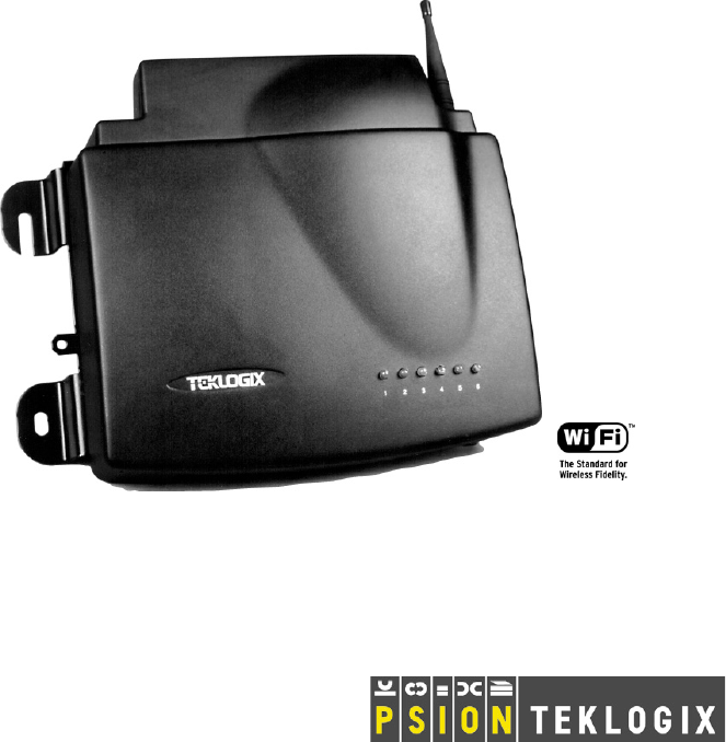
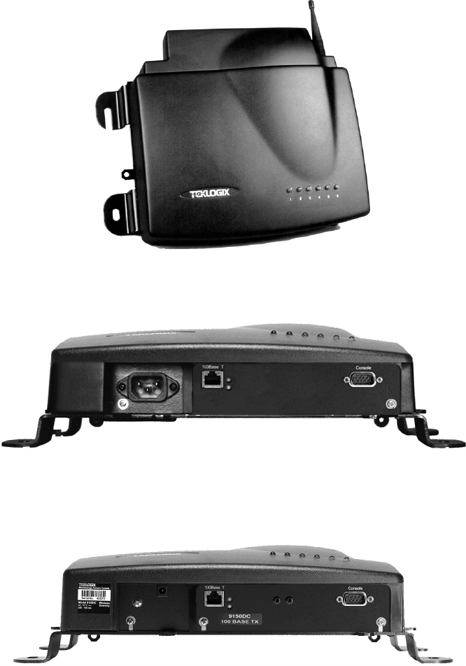
Figure 1.1 The 9150 Wireless Gateway - Front View
Figure 1.2 The 9150T Wireless Gateway - Bottom View
Figure 1.3 The 9150DC Wireless Gateway - Bottom View
Chapter 1: Introduction
Access Point Functions
6Teklogix 9150 Wireless Gateway User Manual
1.3.1 Access Point Functions
As an access point connected to a wired network, the 9150 Wireless Gateway forms
a communication link between Teklogix RF terminals or wireless access point
clients and a Teklogix Network Controller or a host computer. It communicates over
an IEEE 802.11b RF data link with terminals, and over a cable with the network
controller or a host computer. The 9150 can be connected to the network through an
Ethernet connection. The diagram in Figure 4.1 on page 61 illustrates a 9150 access
point connection between a Teklogix 9400 Network Controller on Ethernet and
IEEE 802.11 wireless devices.
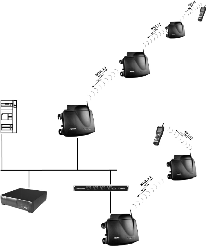
Two 9150 Wireless Gateways can be used as an 802.11b bridge connecting two sep-
arate wired networks. Another feature is that the 9150 can be used as an 802.11b
wireless access point to extend coverage area or for locations difficult to wire (see
Figure 1.4 on page 10). For information on the 9150 as an access point, see “IEEE
802.11b Protocol” on page 8 and Chapter 4: “Access Point Configuration”.
1.3.2 Base Station Functions
As a base station or Remote Radio Module (RRM) connected to a wired network,
the 9150 provides a link between the local area network and the wireless network
consisting of Teklogix mobile terminals, and wireless base stations such as the 9150
Wireless Gateway. The 9150 and 9400 Network Controller (or host using a Teklogix
Software Development Kit) communicate using the 9010 proprietary protocol with
TCP/IP over Ethernet connectivity. Wlan protocol enables the wired 9150 to com-
municate with 9150s without cable attachments (see Figure 5.1 on page 100).
For information on configuring the 9150 as a base station or RRM, see Chapter 5:
“Base Station Configuration”. For Wlan, see “Wlan Protocol” on page 11.
1.3.3 Mini-Controller Functions
The 9150 is equipped with some emulation capabilities, allowing it to act as a mini-
controller. When a 9150 is configured as a mini-controller, Teklogix terminals can
emulate an ANSI, 5250 or 3274 terminal via a 9150 rather than through a 9400
Network Controller.
To configure the 9150 as a mini-controller, see Chapter 6: “Mini-Controller Config-
uration”. For a generalized system diagram, see Figure 6.1 on page 142.

Teklogix 9150 Wireless Gateway User Manual 7
Chapter 1: Introduction
Radio Options
1.4 Radio Options
The 9150 supports 802.11b WLAN CF card USI radio Model CF-B-AG-02.
1.5 Radio Protocols
RF protocols allow terminals to communicate with a base station by sharing the use
of a radio channel in an efficient way. Teklogix systems use one of three types of RF
protocols: the Teklogix Adaptive Polling/Contention protocol, the Teklogix Wireless
LAN (Wlan) protocol, or the non-proprietary IEEE 802.11b protocol. When used as
a base station, the 9150 uses either the Adaptive Polling/Contention protocol or the
Wlan protocol. These protocols cannot be mixed on a single system. When used as
an access point device, the 9150 employs the IEEE 802.11b protocol. The protocols
are described in the following sections.

Chapter 1: Introduction
IEEE 802.11b Protocol
8Teklogix 9150 Wireless Gateway User Manual
1.5.1 IEEE 802.11b Protocol
The IEEE 802.11b protocol is an OSI standard for Wireless Local Area Networks
(WLANs). With this standard, any IEEE 802.11b radio can communicate with any
other similarly-equipped device. However, IEEE 802.11b does not provide a stan-
dard for a total WLAN system. IEEE 802.11b solely standardizes two communica-
tions layers: Physical (PHY) and Medium Access Control (MAC). Three different
PHY layer media are covered: 2.4 GHz Direct Sequence Spread Spectrum radio,
2.4 GHz Frequency Hopping Spread Spectrum radio, and infrared. Each station
in a WLAN system has its own unique MAC address.
Important: Equipment using one physical medium (e.g. Frequency Hopping
versus Direct Sequence) will not interoperate with equipment
using a different physical medium.
IEEE 802.11b uses 2.4 GHz radios of relatively low power. The range is limited
to no more than a hundred feet or so, depending on the conditions, and is usually
restricted to “line of sight” operation. Therefore, most wireless networks need more
than one coverage area, with terminals moving between the areas. To integrate
those areas, systems using IEEE 802.11b protocol for their wireless networks
require an IEEE 802.11b-equipped bridge device (or access point), such as the
9150 Wireless Gateway.
Using bridging software, the 9150 Wireless Gateway enables communication
between any wireless IEEE 802.11b-equipped stations and LAN stations operating
on Ethernet. The 9150 itself is resident on the LAN and functions as a MAC bridge,
providing transparent integration between the stations on the wireless and
wired networks.
Each terminal is associated with one 9150. A frame from an RF terminal is sent to
the 9150 that the terminal is associated with. The terminal puts a destination MAC
address in the frame, which specifies a hardware address on the wired LAN side.
Because the receiving 9150 is connected to an Ethernet network, it encapsulates the
data in an Ethernet frame, including the destination MAC address specified by the
terminal. The 9150 then sends the frame onto the physical network; the frame is
picked up by whichever device is at the destination hardware address.
When sending frames from the LAN side, the sending device puts the MAC address
of the terminal in the frame header. Whichever 9150 has that terminal associated
with it, takes the frame and passes it over the RF to the terminal. By passing frames
in this way, the 9150 is acting as a MAC bridge.

Teklogix 9150 Wireless Gateway User Manual 9
Chapter 1: Introduction
IEEE 802.11b Protocol
1.5.1.1 Inter-Access Point Protocol (IAPP)
The Inter-Access Point Protocol (IAPP) is an extension to the IEEE 802.11b proto-
col. IAPP facilitates roaming of mobile stations across different Basic Service Sets
(see Note below) and specifies how access points communicate with each other.
Note: A Basic Service Set (BSS) is a set of stations (terminals) controlled by a
single coordination function, in this case by the 9150 Wireless Gateway
functioning as an access point within the terminals’ radio coverage area.
In a multiple-9150 system, IAPP informs the other 9150 Wireless Gateways when a
new 9150 becomes active, and enables the awareness of the 9150s of each other.
With IAPP, an IEEE 802.11b system can operate on one or more channels, with
terminals moving between the 9150s. Although each terminal is associated with one
9150, it can re-associate with another 9150 to maintain uninterrupted communica-
tions. The newly-associated 9150 will receive the terminal’s data frames and pass
them onto the LAN. Returning frames are no longer accepted by the original 9150,
which has disassociated from that terminal. The returning frames are now accepted
by the newly-associated 9150 and passed over the RF to the terminal.
1.5.1.2 Psion Teklogix’ 802.IQ Protocol
802.IQ is a Psion Teklogix proprietary optimized protocol that enables terminals to
operate on a wireless LAN in a network that supports both TCP/IP and 802.IQ pro-
tocol simultaneously. 802.IQ protocol is available in two versions: 802.IQv1 and
802.IQv2. The 9150 can support both versions of the protocol at the same time (ter-
minals must use only one).
802.IQv1 protocol is a wireless LAN routing scheme that provides greater perfor-
mance in an 802.11b wireless network than is possible with TCP/IP routing. The
9150 bridges the 802.IQv1 wireless and TCP/IP wired networks. A terminal can
communicate with the 9150 access point using either TCP/IP or 802.IQv1 protocol,
which makes possible a system with dual-operability.
802.IQv2 protocol is an enhanced version of the 802.IQv1 protocol that transports
packets over the UDP layer. It provides all the 802.IQv1 functionality, with the added
features of software upgrade capability over RF, the ability to add third-party access
points between controllers and terminals, and integration into the mapRF system if desired.
For detailed information on configuring the 9150 as an 802.IQv1 access point, see
“802.IQ Version 1 Configuration Menu” on page 64. For information on configuring
the 9150 as an 802.IQv2 mini-controller, see “802.IQ V2 Features Menu” on page
192. Please see Figure 1.4 on page 10 for a generalized system diagram.
Chapter 1: Introduction
IEEE 802.11b Protocol
10 Teklogix 9150 Wireless Gateway User Manual
Figure 1.4 9150 Wireless Gateway: Wireless Access Point Configuration
9150
Wireless Gateway
9400 Network Controller
9150DC Wireless Gateway
Host
9100 PowerBaseT
ETHERNET TCP/IP
Chapter 1: Introduction
Wlan Protocol
12 Teklogix 9150 Wireless Gateway User Manual
Only one base station or terminal may transmit at one time. When the channel
is clear, a combination of preset priorities and random choices determines who
“goes next”. Even if two transmitters attempt to send at the same time, message
acknowledgements and retransmissions prevent any data from being lost.
Terminals moving through the Wlan communicate with the base stations that
provide the best communication path to a wired base station. If multiple channels
are used, the terminal looks for a better channel only if it cannot find an acceptable
path back on its current channel.
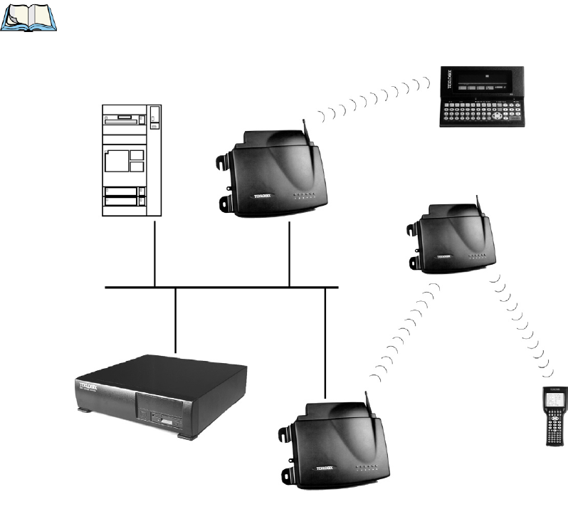
For detailed information on configuring the 9150 as a base station, please see
Chapter 5: “Base Station Configuration”. For a generalized system diagram, see
Figure 1.5.
Figure 1.5 9150 Base Station/RRM Configuration
ETHERNET
TCP/IP
9150 Wireless Gateway
9400 Network Controller
9150
Wireless Gateway
Host

Teklogix 9150 Wireless Gateway User Manual 13
INSTALLATION REQUIREMENTS 2
2.1 Choosing The Right Location ..................15
2.1.1 Environment . . . . . . . . . . . . . . . . . . . . . 15
2.1.1.1 9150 Wireless Gateway . . . . . . . . . . . . 15
2.1.1.2 9100 PowerBaseT . . . . . . . . . . . . . . . 16
2.1.2 Maintenance . . . . . . . . . . . . . . . . . . . . . 16
2.1.3 Power And Antenna Cables . . . . . . . . . . . . . 17
2.1.3.1 Power . . . . . . . . . . . . . . . . . . . . . 17
2.1.3.2 Antennas....................17
2.2 Connecting To External Devices.................19
2.2.1 Ports.........................19
2.2.2 LAN Installation: Overview . . . . . . . . . . . . . 19
2.2.3 LAN Installation: Ethernet . . . . . . . . . . . . . . 20
2.2.3.1 9150T Wireless Gateway . . . . . . . . . . . 20
2.2.3.2 9150DC Wireless Gateway . . . . . . . . . . 20
2.2.3.3 Ethernet Cabling. . . . . . . . . . . . . . . . 21
2.2.3.4 9100 PowerBaseT Mid-Span Power Supply . 22
2.2.4 Status Indicators (LEDs). . . . . . . . . . . . . . . 25
2.2.4.1 9150T and 9150DC . . . . . . . . . . . . . . 25
2.2.5 Connecting A Video Display Terminal . . . . . . . 26
2.3 Changing The Configuration With A Web Browser . . .....26

Teklogix 9150 Wireless Gateway User Manual 15
Chapter 2: Installation Requirements
Choosing The Right Location
Warning: The 9150 must be installed by qualified Psion Teklogix personnel.
2.1 Choosing The Right Location
Typically, Psion Teklogix conducts a site survey in the plant and then recommends
the preferred locations for the 9150s. These locations provide good radio coverage,
minimize the distance to the host computer or network controller, and meet the
environmental requirements.
2.1.1 Environment
2.1.1.1 9150 Wireless Gateway
The 9150 should be located in a well-ventilated area and should be protected from
extreme temperature fluctuations (i.e. direct heater output, shipping doors or
direct sunlight). If a protective cover is required, it must have enough ventilation
to maintain the 9150’s surface at or near room temperature.
Refer to Chapter 8: “Specifications” for a more detailed description of environmen-
tal requirements. Keep in mind that the long term stability of this equipment will
be enhanced if the environmental conditions are less severe than those listed in
this manual.
The 9150 should be situated away from the path of vehicles and free from water or
dust spray. The 9150 should only be mounted in the upright position, as shown in
Figure 2.1 on page 16. This orientation minimizes the risk of water entering the
9150, should the unit accidentally be sprayed.
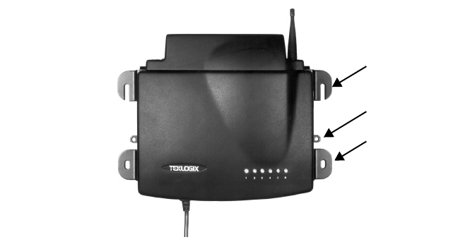
The 9150 is attached to a vertical surface using four fasteners on the rear plate (type
of fasteners are dependent on mounting surface). The top two holes in the rear plate
are slots, allowing the unit to be hung in position before the remaining bolts are
installed, thus easing installation. The bolts used for installation are SAE 1/4-20.
Chapter 2: Installation Requirements
Maintenance
16 Teklogix 9150 Wireless Gateway User Manual
Figure 2.1 9150 Installation Position
2.1.1.2 9100 PowerBaseT
The 9100 PowerBaseT is a 19-inch rack-mounted device intended for installation in
the same environment as your hub or switch. For detailed information on the 9100,
please refer to page 22.
2.1.2 Maintenance
The 9150 has no internal option switches and does not require physical access; all
configuration settings are done remotely (see Chapter 3: “9150 Main Configura-
tion”). Environmental and radio communication considerations do still apply.
Mounting Slot
Cable Tie Mount
Mounting Hole

Teklogix 9150 Wireless Gateway User Manual 17
Chapter 2: Installation Requirements
Power And Antenna Cables
2.1.3 Power And Antenna Cables
2.1.3.1 Power
To prevent accidental disconnection and stress on the 9150, antenna and power
cables should be secured within 30 cm of the unit. Secure the cables with ties to
the cable tie mounts on the 9150 (see Figur e2.1 on page 16). A single phase power
outlet (range 100 to 240 VAC rated 1.0A minimum) should be installed within one
metre (3.1 feet) of the 9150. The 9150 automatically adjusts to input within that
power range. The power cable is removable and is available in the power type spe-
cific to your location.
To eliminate the need for AC wiring, the 9150DC Wireless Gateway is powered
over its Ethernet connection. For detailed information, please see page 20.
Warning: To avoid electric shock, the power cord protective grounding
conductor must always be connected to ground.
2.1.3.2 Antennas
Warning: This transmitter must not be co-located or operating in conjunction with
any other antenna or transmitter.
Warning: Equipment requires professional installation of antennas.
The maximum output power from the radio transmitter is 36 mW
List of antennas: 1. Centurion EXE-2400-SMRP
2. Mobile Mark IMAG5-2400 3. Cushcraft S2403BP12NF
4. Larsen FB45T2400 5. Cushcraft Patch Antenna S2307AMP10SM
or S2307MP10SMF

Chapter 2: Installation Requirements
Power And Antenna Cables
18 Teklogix 9150 Wireless Gateway User Manual
Warning: Never operate the 9150 without a suitable antenna or a dummy load.
Connection to Outdoor Antenna: Outdoor antenna to be earthed in
accordance with International Standard EN 50083-1 (1993),
“Cabled Distribution Systems for Television and Sound Signals -
Safety Requirements”. The antenna must be installed by a
qualified service person and installed according to local electrical
installation codes. The antenna should be located such that it is
always at least 15 ft (4.6 m) high and 10 ft (3 m) from the user and
other people working in the area.
Warning: For RF safety considerations, users are not allowed to approach
close to the antenna.
Psion Teklogix supplies the coaxial cable required to connect the 9150 to the
antenna. When determining the location of the antenna, the coverage requirements
of the antenna are considered in conjunction with the environmental requirements of
the 9150.
The coaxial cable must be routed and secured using wire anchors and/or coaxial nail
clips. A few extra inches of cable are required near the antenna and the 9150 to
make disconnection easier.

Teklogix 9150 Wireless Gateway User Manual 19
Chapter 2: Installation Requirements
Connecting To External Devices
2.2 Connecting To External Devices
This section contains general guidelines for connecting the 9150 to external
devices such as network controllers, base stations, host computers, PCs and video
display terminals.
2.2.1 Ports
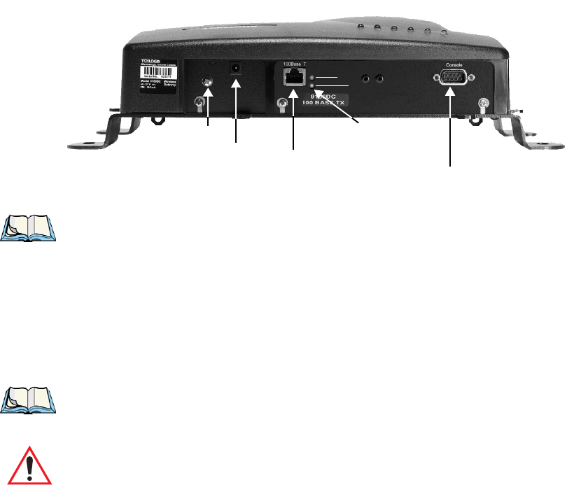
Figure 2.2 below shows the locations of the port and power connectors on the base
of the 9150T [100BaseT Ethernet]; for the 9150DC, see Figure 2.3 on page 21). The
port pinouts are described in Appendix B: “Port Pinouts And Cable Diagrams”.
Figure 2.2 9150T Ethernet LED Locations*
*Note: The location of the LEDs is the same on the 9150DC (see Figu re2.3 on page 21).
2.2.2 LAN Installation: Overview
Because the 9150 provides Ethernet connectivity, it can be added to an existing LAN.
Generally, LAN installations are handled with the help of the network administrators,
as they are familiar with their network and its configuration.
Once the 9150 is installed, connected and powered on, the system administrator can
access the unit to check the configuration and to assign the 9150 its unique IP address.
This may be done through the Console port or through the network (see “Connecting
AC Power Socket10BaseT/100BaseT Ethernet Adaptor
Green
LEDs
Console Port
Yellow
LED: 1 4 563
2
Operating Status

Chapter 2: Installation Requirements
LAN Installation: Ethernet
20 Teklogix 9150 Wireless Gateway User Manual
A Video Display Terminal” on page 26 and “Changing The Configuration With A
Web Browser” on page 26). Subsequent changes in the network, such as the addition
of stations or users, would also require that the 9150 configuration be changed.
Important: Once the 9150 is configured and rebooted the first time, the DHCP
or Bootp option should be disabled—unless the 9150 obtains its IP
address from a server, or the system administrator intends to
update the software through bootp. For detailed information, see
“Network Interface Configuration Protocol” on page 52.
2.2.3 LAN Installation: Ethernet
2.2.3.1 9150T Wireless Gateway
The 9150T is a high-performance controller that supports 100Mb/s Fast Ethernet
LANs, as well as 10Mb/s, with both full and half duplex operation.
It comes equipped with:
• 10BaseT/100BaseT card (using a category-5 twisted pair cable, an RJ-45
connector, running at a rate of 10 or 100Mb/s).
Note: The 9150T does not support any connection type other than Ethernet
10BaseT and 100BaseT.
See Figure 2.2 on page 19 for the connector locations. Since these ports are auto-
selecting, jumper or configuration settings are not required. The maximum packet
size supported over the network is 1500 bytes. This parameter is not set at the 9150,
but should be set at the host. For a description of port pinouts, please refer to Appen-
dix B: “Port Pinouts And Cable Diagrams”.
2.2.3.2 9150DC Wireless Gateway
The 9150DC incorporates most of the features of the 9150T. However, while the
9150T is AC-powered, the 9150DC Wireless Gateway is DC-powered, eliminating
the need for AC wiring. The 9150DC is powered through a Category 5 ethernet
cable that carries power and data signals simultaneously.
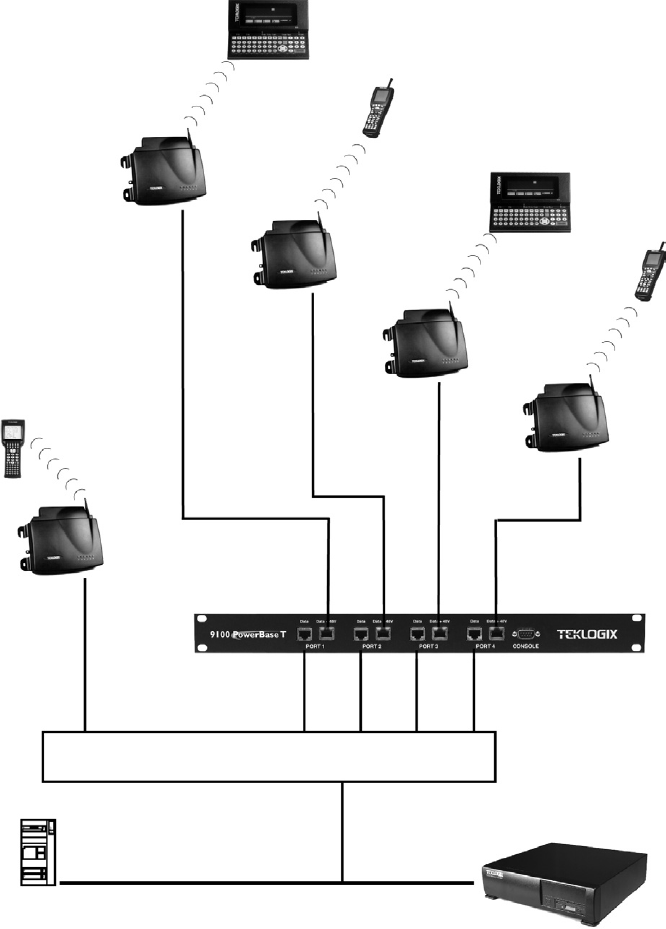
The 9150DC is connected to the 9100 PowerBaseT, a remote power module that
inserts 48VDC power on the spare conductors of the ethernet cable to the 9150DC
(for detailed information on the 9100, see page 22; for a system diagram, see
Teklogix 9150 Wireless Gateway User Manual 21
Chapter 2: Installation Requirements
LAN Installation: Ethernet
Figure 2.5 on page 23). Inside the 9150DC, a DC/DC converter is used to step down
the +48 V provided by the 9100 to the +5 V required to power up the main compo-
nents of the gateway.
The 9150DC may also be powered via the Auxiliary Supply (48 VDC) power jack,
which is adjacent to the ethernet RJ-45 connector (see Figure 2.3). For a description
of RJ-45 port pinouts, refer to Appendix B: “Port Pinouts And Cable Diagrams”.
Figure 2.3 The 9150DC Wireless Gateway
Notes: The 9150DC does not support any connection type other than Ethernet
10BaseT and 100BaseT.
The 9150DC supports dual 802.11 radios, but does not support Narrow
Band or TekLAN 902 MHz radios.
2.2.3.3 Ethernet Cabling
The maximum cable segment length allowed between repeaters for both the 9150T
and 9150DC (10BaseT/100BaseT Ethernet cabling) is 100 m.
Note: For the 9150DC (see “Important” note on page 22), this cable length is
measured from hub to 9150, including mid-span insertion of the 9100
PowerBaseT.
Important: For Main Logic Board (MLB) P/N 30183-301 Rev F only: When
connecting the RJ-45 Ethernet cable to the 9150T (AC power ver-
sion), ensure that the snap-on ferrite for cables (P/N 97776) is
placed on the cable as closely as possible to the RJ-45 jack. To
determine which version of the MLB is resident in your 9150,
please contact Psion Teklogix Support Services (see page A-1).
AC Power Jack
Console Port
10/100BaseT Ethernet Adaptor
LED: 1 4 5 63
2
Yellow
Green
LEDs
Ground Screw
Chapter 2: Installation Requirements
LAN Installation: Ethernet
22 Teklogix 9150 Wireless Gateway User Manual
2.2.3.4 9100 PowerBaseT Mid-Span Power Supply
Overview
The 9100 PowerBaseT module is designed to provide power over Ethernet and may
be referred to as a “mid-span power supply” in that it intercepts the Ethernet cables
between a hub/switch and the DC-powered 9150DC, as illustrated in Figur e2.5 on
page 23. The 9100 has an internal, universal AC/48VDC power supply and routes
DC power to each of its independent Data + 48V output Ports, following successful
detection of a suitable powered device (a 9150DC). The Resistor Detection method
is employed for this purpose, following application of power to the 9100, or connec-
tion of a powered device to a powered-on Port. The 9100 determines whether each
connected device needs to be powered or not by determining if there is a signature
resistor in the powered device between the 4/5 and 7/8 “spare” wire pairs. Subse-
quent disconnection of such a device is also detected. There are four identical, inde-
pendent resistor/transistor networks, one for each output port. 48VDC is supplied
via the unused pairs of a standard Ethernet Category 5 cable, while the Ethernet data
lines (4 of the 8 conductors in the cable) are passed through the 9100 to the 9150DC.
The 9150DC can accept power via either the unused pairs, or via the data pairs of a
10/100BaseT system connected to a suitable Power Over Ethernet switch/hub.
Important: The 9100 does not contain any transceivers (the data signals are
passed through) and is therefore subject to the 100 m cable length
limitation (including the cable from the hub/switch to the 9100
PowerBaseT and any subsequent length added to the 9150DC).
The 9100 PowerBaseT provides power for up to four 9150DCs (13 Watts per
channel maximum), connected by twisted pair cables up to 100 m in length. See
page 206 for power specifications.
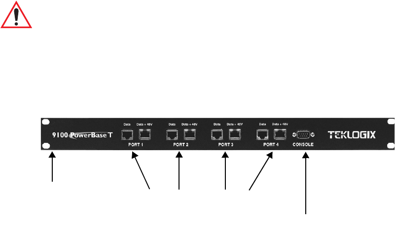
Figure 2.4 The 9100 PowerBaseT Console Port
RJ-45 Ports include LEDs for Powered Lines
19" Rack Mount
Teklogix 9150 Wireless Gateway User Manual 23
Chapter 2: Installation Requirements
LAN Installation: Ethernet
Figure 2.5 9100 PowerBaseT System Architecture
ETHERNET TCP/IP
9150DC
Non-powered Ethernet
Powered Ethernet
Powered Ethernet
Powered Ethernet
Powered Ethernet
SWITCH/HUB
9100 PowerBaseT
Wireless Gateway
9150DC
Wireless Gateway
9150DC
Wireless Gateway
9150DC
Wireless Gateway
9150
Wireless Gateway
9400 Network Controller
Host

Chapter 2: Installation Requirements
LAN Installation: Ethernet
24 Teklogix 9150 Wireless Gateway User Manual
Functions
The 9100 PowerBaseT delivers 13 Watts per port for a total of 52 Watts. Power sup-
plied to each of the four Ethernet ports is protected from over-voltage and current
limiting within the power supply by the 9100’s microcontroller. Its primary
functions are:
1. Resistor Detection (described in Overview on page 22).
2. Fault Monitoring (page 197).
3. Power Monitoring (page 198).
4. Diagnostics and Status Reporting (page 198).
Status Indicators
The LEDs present at each port on the front panel of the 9100 (Figure 2.4 on page
22) indicate the status of the 9100 and the individual ports, as determined by the
microcontroller. Table 2.1 below shows the LED state meanings.
Note: Once a fault/abnormal condition is detected, the LED indicators will
continue to blink until the condition has been corrected, with or without
manual intervention.
Status Notes Yellow LED Green LED
Normal Device present and
powered On On
Normal / Fault Device not connected /
not detected Off On
Fault Undercurrent fault
(device disconnected) Slow blink On
Fault Overcurrent fault Fast blink On
Fault 9100 main power
supply fault Fast blink (all ports) Fast blink (all ports)
Test Mode Port in test mode
(enabled via console) Fast blink Fast blink
Test Mode Port disabled
(via console) Off Slow blink
Table 2.1 LED Indicator States

Teklogix 9150 Wireless Gateway User Manual 25
Chapter 2: Installation Requirements
Status Indicators (LEDs)
2.2.4 Status Indicators (LEDs)
2.2.4.1 9150T and 9150DC
The high-performance 9150T (see page 20 for details) and DC-powered 9150DC
(see page 20 for details) both have six status indicators on the front of the enclosure,
and an additional two status indicators on the base of the enclosure next to the RJ-45
connector port, as shown in Figure 2.2 on page 19. The numbered and coloured
LEDs on the front of the unit indicate the operating status for each port, as described
in Table 2.2. The coloured LEDs beside the RJ-45 port indicate the operating status of
the resident 10BaseT/100BaseT card, as described in Table 2.3 on page 26.
LED
Number Name Function Colour
1 Ethernet link Link indicator for 10BaseT/100BaseT:
ON = good link; OFF = no link yellow
2 Ethernet activity Ethernet LAN activity (Rx/Tx) green
3PC Card A status
1PC Card A activity (Rx/Tx) yellow
4 PC Card B status1PC Card B activity (Rx/Tx) green
5SLIM
2SLIM card activity yellow
6Power LED flashing = BIST3 running/error detected
LED On solid = BIST3 Passed
LED Off = no power to unit green
1When a TekLAN 902 MHz radio is installed, the PC Card status LEDs blink only when
data is received from or transmitted to a terminal. When a TRX7370 narrow band radio is
installed, these LEDs blink for all received and transmitted data traffic.
(Note: the 9150DC only supports 802.11 radios.)
2LED #5 shows no activity, since the 9150T and 9150DC do not support serial connectivity.
3Built-in Self-Test.
Table 2.2 9150T And 9150DC LED Functions: Front Enclosure

Chapter 2: Installation Requirements
Connecting A Video Display Terminal
26 Teklogix 9150 Wireless Gateway User Manual
2.2.5 Connecting A Video Display Terminal
An ANSI compatible video display terminal (e.g., DEC VT220 or higher), or a PC
running terminal emulation, is used for diagnostic purposes and to configure the IP
address for the first time before the 9150 can be accessed using a Web Browser (see
“Configuring The IP Address” on page 29).
The terminal is connected to the port labelled “Console” on the 9150 (see Figure 2.2
on page 19). This port is normally set to operate at 19,200 baud, 8 bits, 1 stop bit, no
parity. To comply with Part 15 of the FCC rules for a Class B computing device,
only the cable supplied (Part no. 19387) should be used.
2.3 Changing The Configuration With A Web Browser
The 9150 Flash memory can be reconfigured remotely via the network using a stan-
dard HTML Web Browser such as Netscape Navigator (version 4.05 or later) or MS
Internet Explorer (version 4.0 or later). See Chapter 3: “9150 Main Configuration”
for instructions on changing the parameters and general configuration settings.
For configuration information on setting up the 9150 as an access point device, refer
to Chapter 4: “Access Point Configuration”.
For configuration information on setting up the 9150 as a base station, refer to
Chapter 5: “Base Station Configuration”.
For configuration information on setting up the 9150 as a mini-controller, refer to
Chapter 6: “Mini-Controller Configuration”.
LED Colour Status Function
Green ON 100BaseT speed selected
Green OFF 10BaseT speed selected
Yellow ON Full duplex operation selected. (10BaseT or 100BaseT)
Yellow OFF Half duplex operation selected. (10BaseT or 100BaseT)
Table 2.3 9150T And 9150DC Ethernet LED Functions: Base Of Enclosure

Teklogix 9150 Wireless Gateway User Manual 27
9150 MAIN CONFIGURATION 3
3.1 Configuration Main Menu....................29
3.2 Configuring The IP Address . ..................29
3.3 Accessing The Menus ......................31
3.4 General Configuration Menu Options . . . ...........33
3.4.1 Interfaces. . . . . . . . . . . . . . . . . . . . . . . 34
3.4.1.1 10BaseT Ethernet . . . . . . . . . . . . . . . 34
3.4.1.2 100BaseT Ethernet . . . . . . . . . . . . . . 36
3.4.1.3 Slot n: PC Card Radio . . . . . . . . . . . . . 38
3.4.2 Users.........................39
3.4.3 SNMP........................40
3.4.3.1 mapRF . . . . . . . . . . . . . . . . . . . . . 40
3.4.3.2 System Parameters. . . . . . . . . . . . . . . 41
3.4.3.3 Enable Proxy for non-IP terminals . . . . . . 42
3.4.3.4 Proxy throttling . . . . . . . . . . . . . . . . 42
3.4.3.5 SNMP Communities and Trap Receivers . . . 42
3.4.4 Redundancy . . . . . . . . . . . . . . . . . . . . . 43
3.4.5 SNTP.........................47
3.4.6 TCP/IP Parameters..................48
3.4.6.1 Route Table . . . . . . . . . . . . . . . . . . 49
3.4.6.2 Host Table...................50
3.4.6.3 Network Interface Configuration Protocol . . 52
3.4.6.4 DNS......................54
3.4.7 Serial Ports Parameters. . . . . . . . . . . . . . . . 55
3.4.7.1 Console Port..................55
3.4.7.2 Serial Port...................55
28 Teklogix 9150 Wireless Gateway User Manual
3.5 Access Point/Base Station/Mini-Controller Menus .......56
3.6 Miscellaneous Commands Menu Options ............57
3.6.1 System Info......................57
3.6.2 Reboot Unit. . . . . . . . . . . . . . . . . . . . . .58

Teklogix 9150 Wireless Gateway User Manual 29
Chapter 3: 9150 Main Configuration
Configuration Main Menu
3.1 Configuration Main Menu
The 9150 Flash memory can be reconfigured remotely via the network using a
standard HTML Web Browser such as Netscape Navigator (version 4.05 or later) or
MS Internet Explorer (version 4.0 or later).
Note: To ensure that the 9150 configuration screens appear properly when
using Netscape Navigator, in your browser go to Edit/Preferences/
Appearance/Colors. Make sure that the box for “Always use my colors,
overriding document” is NOT checked.
The 9150 Configuration program allows various configuration parameter settings to
be changed, added or deleted.
Important: The 9150 must be warm rebooted after parameter changes are
made, including configuring the IP address (see below), in order
for the changes to take effect. For details, see “Reboot Unit” on
page 58.
3.2 Configuring The IP Address
Before the configuration menus can be accessed using your Web Browser, the 9150
must be assigned an IP address using a PC console connection. Virtually any PC
can be connected to the console port of the 9150, provided that the PC has a
terminal communication program such as the Windows® HyperTerminal® utility or
Procomm® Plus for Windows. These programs emulate an ANSI terminal such as
VT220 or higher. Cable no. 19387 should be used to connect the PC to the 9150.
Make sure the communications settings on your PC are set to 8 bits, 1 stop, no
parity, and that the baud rate of the serial port matches that of the 9150 console port
(19,200 baud).
After the PC is attached and turned on, press the <RETURN> key several times until
the “>” prompt appears. The commands used to configure IP addresses are
described here. For the command to flash upgrade the 9150 software using TFTP,
please refer to page 53.
If your system uses a DHCP or BOOTP server to assign IP addresses, make sure that
the appropriate option is enabled (see “Network Interface Configuration Protocol”
on page 52). Once enabled, and the 9150 is rebooted, you will be able to access the
9150 configuration menus through the Web Browser, using the IP address identified

Chapter 3: 9150 Main Configuration
Configuring The IP Address
30 Teklogix 9150 Wireless Gateway User Manual
in the server's address table. If you do not use a server, make sure that the DHCP or
BOOTP option is disabled and continue with the configuration commands to manu-
ally assign an IP address.
Important: When your configuration is completed, the changes should be
saved to flash by entering the following command (commands are
case-sensitive):
>cfg commitCache
To display the bootp setting:
>cfg get system.dobootp
To enable bootp:
>cfg put system.dobootp 1
To disable bootp:
>cfg put system.dobootp 0
To display the default IP address:
>cfg get interface.1.defaultipaddress
To configure the default IP address (xxx.xxx.xxx.xxx represents the IP address):
>cfg put interface.1.defaultipaddress xxx.xxx.xxx.xxx
To display the default gateway:
>cfg get system.defaultgateway
To configure the default gateway:
>cfg put system.defaultgateway xxx.xxx.xxx.xxx
To display the default subnetmask:
>cfg get interface.1.defaultsubnetmask
To configure the default subnetmask:
>cfg put interface.1.defaultsubnetmask xxx.xxx.xxx.xxx

Teklogix 9150 Wireless Gateway User Manual 31
Chapter 3: 9150 Main Configuration
Accessing The Menus
3.3 Accessing The Menus
When the Web Browser is pointed to the 9150’s IP address, a name and password
dialog box appears. The password is comprised of alphanumeric characters and is
case-sensitive. If you change the password (see “Users” on page 39), set all 9150s to
the same password, and write it down in a secure place.
A default user name “user” and the password “123456” are created on 9150 system
startup if no users are already configured. You can use the default to enter the
Configuration Main Menu for the first time. For security, change this default name
and password immediately after entering the configuration menus. Should you acci-
dentally delete your user names, re-booting the 9150 will re-create the default name
and password so that you can get back in to the unit.
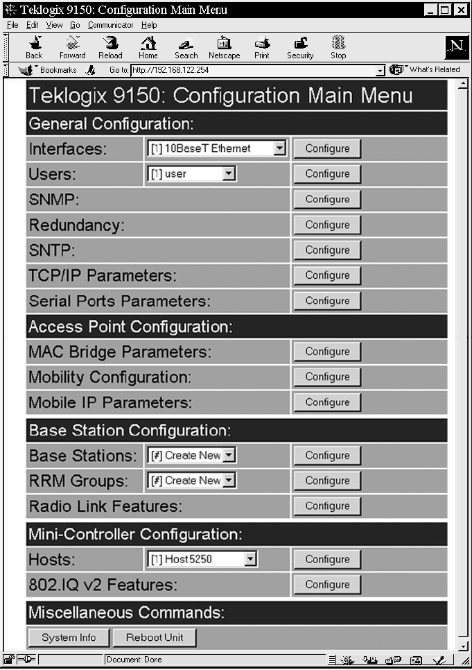
After the password is accepted, the Configuration Main Menu appears. The 9150
software automatically detects the system information of the unit, and most of the
parameters have already been properly configured for each site.
Warning: Parameters should not be altered without a clear understanding of
how they operate. Parameters that are incorrectly set can increase
response time or cause communication difficulties.
• To highlight and move through the different options, use the <TAB> key
or mouse pointer.
• To view and select the items in the listboxes, either press the <UP> or
<DOWN> arrow keys or click on the arrow at the side of the menu and
highlight the item.
• To enter the related configuration sub-menu dialog box, highlight
“Configure” and either press <ENTER> or click on the “Configure” button.
• Where string entry parameters are given in the menus, changes are keyed in.
Numerical parameters can be entered as hexadecimal values. Precede hexa-
decimal values with “0x”.
• To leave a menu page, select either the <OK> or <Cancel> button at
the bottom of the page. Selecting <OK> will save your changes and
exit the page, while selecting <Cancel> will exit the page without saving
the changes.
Important: Do not use the Web Browser’s <Back> button to leave a page.
Chapter 3: 9150 Main Configuration
Accessing The Menus
32 Teklogix 9150 Wireless Gateway User Manual
Figure 3.1 9150 Configuration Main Menu: View From Browser
Teklogix 9150 Wireless Gateway User Manual 33
Chapter 3: 9150 Main Configuration
General Configuration Menu Options
3.4 General Configuration Menu Options
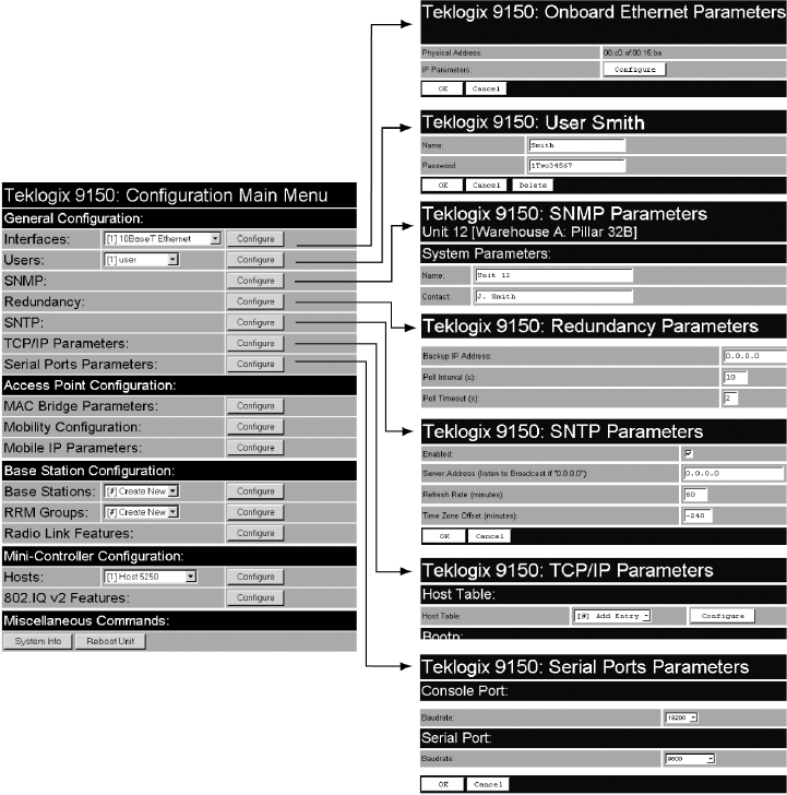
The General Configuration menu on the Configuration Main Menu page presents
five options of sub-menus: Interfaces, Users, SNMP, TCP/IP Parameters, and Serial
Ports Parameters.
Figure 3.2 Overview Of General Configuration Menus
Chapter 3: 9150 Main Configuration
Interfaces
34 Teklogix 9150 Wireless Gateway User Manual
3.4.1 Interfaces
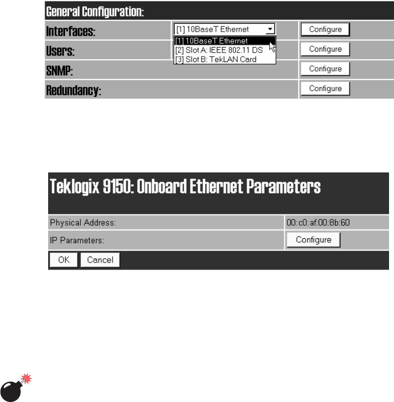
The pull-down menu shown for the Interfaces option indicates which interfaces have
been detected in use by the 9150.
3.4.1.1 10BaseT Ethernet
For the selection 10BaseT Ethernet, entering the “Configure” dialog box will open
the Onboard Ethernet Parameters page for that Ethernet connection, which shows
the 9150’s physical (hardware) address and IP address parameters.
Physical Address
A unique Physical Address is assigned by Psion Teklogix personnel for each 9150.
The values entered for this parameter are presented in hexadecimal in descending
order beginning with the MSB (Most Significant Byte), the highest value, and
ending with the LSB (Least Significant Byte), the lowest value. The allowable value
for each field ranges from 00 to FF.
Warning: It is not advisable to modify the Physical Address. However, if these
values are changed, the Network Administrator must assign a
unique address to each Ethernet station on the network, including
all 9150s.
Teklogix 9150 Wireless Gateway User Manual 35
Chapter 3: 9150 Main Configuration
Interfaces
IP Parameters
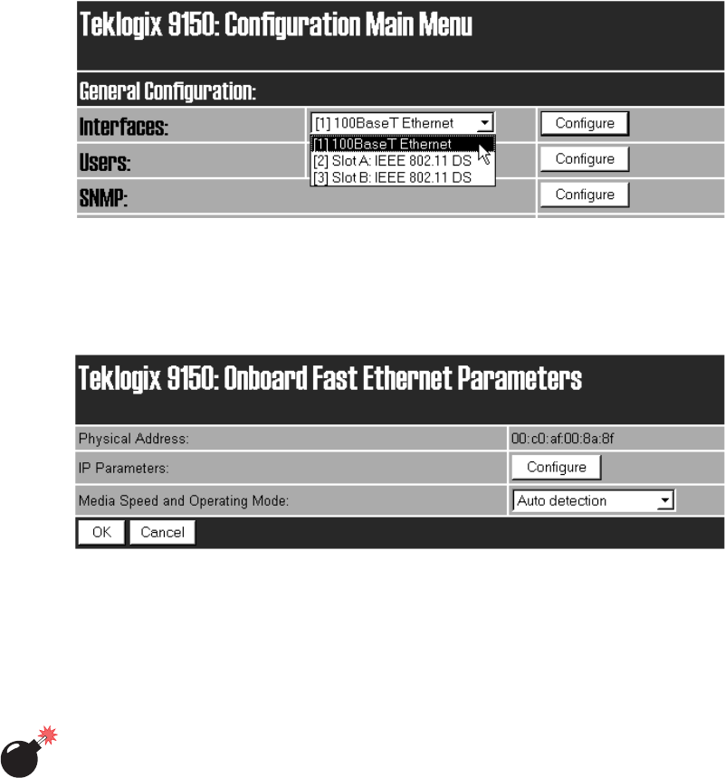
Each 9150 that is connected to a local network has a unique IP address designated
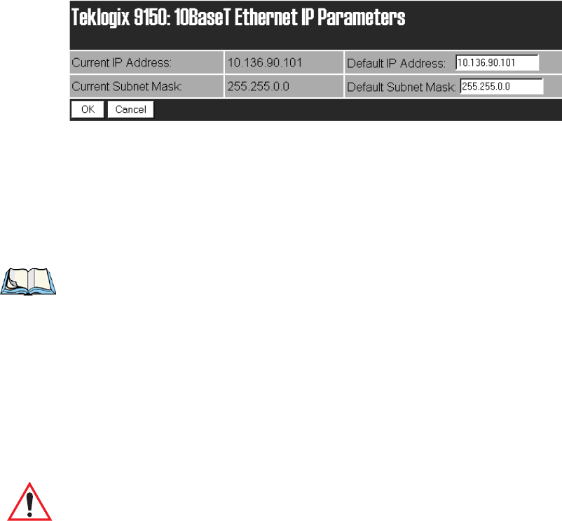
for it. The 10BaseT Ethernet IP Parameters used to assign the IP address are
accessed by entering the “Configure” dialog box.
IP Address
The Current IP Address shown in the read-only field is the IP address currently set
on the 9150. The Default IP Address text box allows you to change the value of the
IP address.
The IP address must be a unique value on the network, so that each 9150 in your
system can be identified. The acceptable value ranges from 0.0.0.0 to
239.255.255.255.
Note: The value 255.255.255.255 is reserved for the broadcast address.
Subnet Mask
The Current Subnet Mask shown in the read-only field is the subnet mask currently
set on the 9150. The Default Subnet Mask text box allows you to change the value of
the subnet mask.
The 9150 uses the Subnet Mask, its own IP address, and the destination IP address to
determine if a packet should be sent on the local network or to a remote segment. If
the destination is found on the local network, the packet is sent directly to its desti-
nation. If the destination resides on a remote network, the packet is routed to the
gateway. Enter your subnet mask in “xxx.xxx.xxx.xxx” notation.
Important: The maximum packet size supported is 1500 bytes. This parameter
is not set at the 9150, but should be set at the host.
The acceptable values range from 0.0.0.0 to 255.255.255.255.
Chapter 3: 9150 Main Configuration
Interfaces
36 Teklogix 9150 Wireless Gateway User Manual
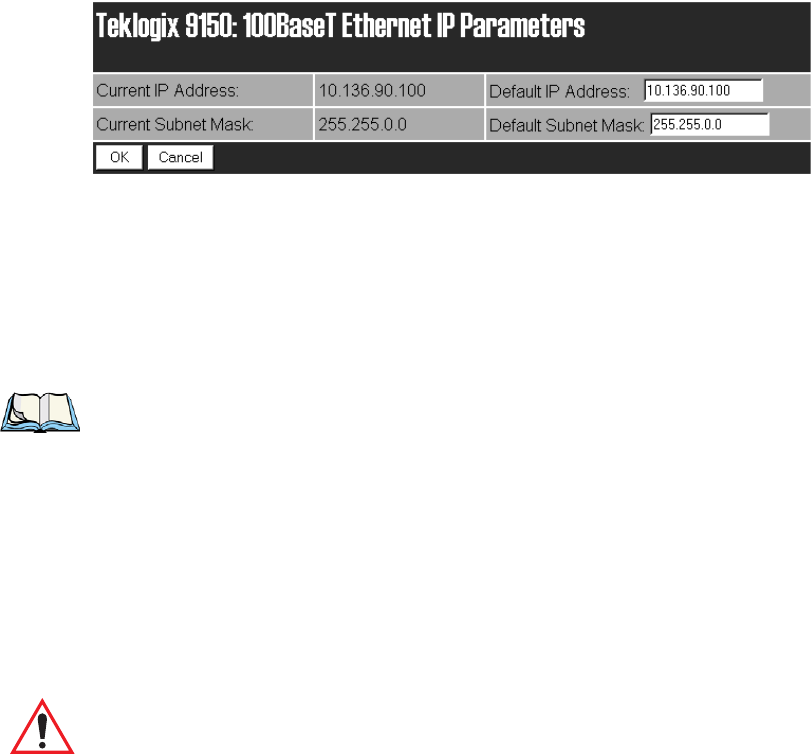
3.4.1.2 100BaseT Ethernet
For the selection 100BaseT Ethernet, entering the “Configure” dialog box will open
the Onboard Fast Ethernet Parameters page for that Ethernet connection, which
shows the 9150’s physical (hardware) address, and give access to the IP address, and
Media Speed and Operating Mode parameters.
Physical Address
A unique Physical Address is assigned by Psion Teklogix personnel for each 9150.
The values entered for this parameter are presented in hexadecimal in descending
order beginning with the MSB (Most Significant Byte), the highest value, and
ending with the LSB (Least Significant Byte), the lowest value. The allowable value
for each field ranges from 00 to FF.
Warning: It is not advisable to modify the Physical Address. However, if these
values are changed, the Network Administrator must assign a
unique address to each Ethernet station on the network, including
all 9150s.
Teklogix 9150 Wireless Gateway User Manual 37
Chapter 3: 9150 Main Configuration
Interfaces
IP Parameters
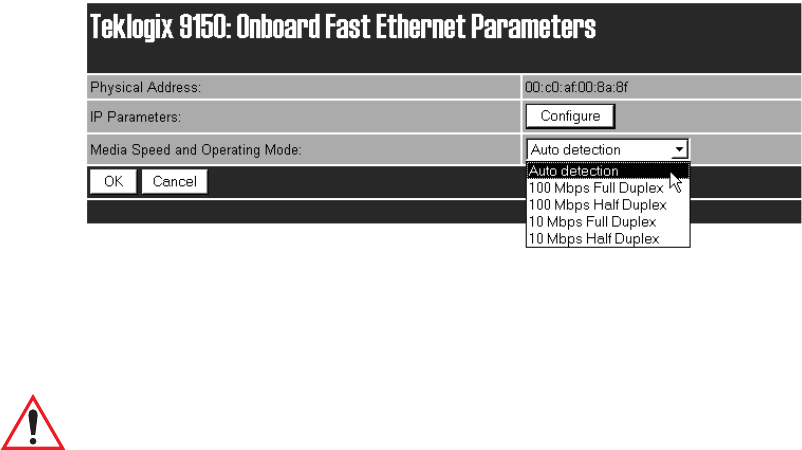
Each 9150 that is connected to a local network has a unique IP address designated
for it. The IP Parameters used to assign the IP address are accessed by entering the
“Configure” dialog box.
IP Address
The Current IP Address shown in the read-only field is the IP address currently set
on the 9150. The Default IP Address text box allows you to change the value of the
IP address.
The IP address must be a unique value on the network, so that each 9150 in your
system can be identified. The acceptable value ranges from 0.0.0.0 to
239.255.255.255.
Note: The value 255.255.255.255 is reserved for the broadcast address.
Subnet Mask
The Current Subnet Mask shown in the read-only field is the subnet mask currently
set on the 9150. The Default Subnet Mask text box allows you to change the value of
the subnet mask.
The 9150 uses the Subnet Mask, its own IP address, and the destination IP address to
determine if a packet should be sent on the local network or to a remote segment. If
the destination is found on the local network, the packet is sent directly to its desti-
nation. If the destination resides on a remote network, the packet is routed to the
gateway. Enter your subnet mask in “xxx.xxx.xxx.xxx” notation.
Important: The maximum packet size supported is 1500 bytes. This parameter
is not set at the 9150, but should be set at the host.
Chapter 3: 9150 Main Configuration
Interfaces
38 Teklogix 9150 Wireless Gateway User Manual
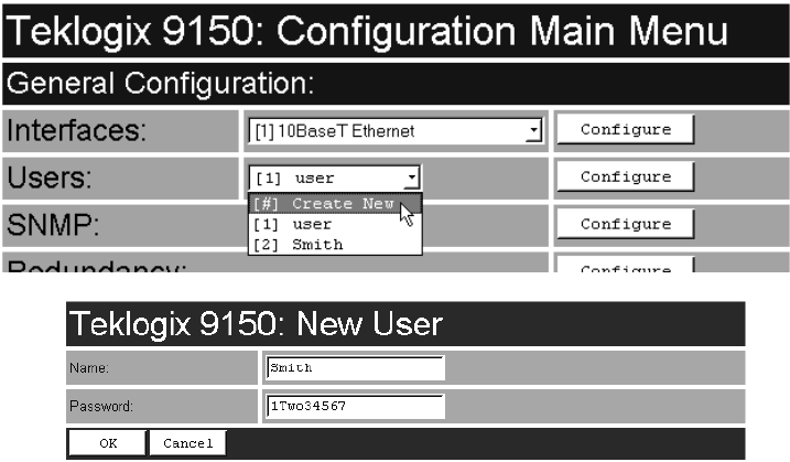
Media Speed and Operating Mode
You can choose the operational mode of the 9150T by selecting the media speed,
either 10 or 100 Mbps, and the operational mode, either full or half duplex. If the
parameter value is left at the default, Auto detection, the 9150T’s physical interface
will be detected, and the speed and mode will be set automatically.
Select the media speed and mode from the drop-down list. The values are:
Auto detection, 100 Mbps Full Duplex, 100 Mbps Half Duplex, 10 Mbps Full
Duplex, or 10 Mbps Half Duplex.
The default value is Auto detection.
Important: If the mode chosen for the 9150 is incorrect, it will become inac-
cessible from the network when it is rebooted. If this occurs, the
9150 will have to be re-configured using the console.
3.4.1.3 Slot n: PC Card Radio
Each PC (PCMCIA) card radio resident in the 9150 will be located in one of two
Slots: A or B. Selecting a PC card will open the sub-menu for that radio.
IEEE 802.11 DS: See “IEEE 802.11 Direct Sequence Radio Parameters Menu” on
page 62 for details on setting the radio parameters for the PC card.
TekLAN Card: See “TekLAN Parameters” on page 102 for details on setting the
radio and Wlan parameters.
Teklogix Narrowband: See “Narrow Band Radio Parameters” on page 106 for
details on setting the radio and polling parameters.
Teklogix 9150 Wireless Gateway User Manual 39
Chapter 3: 9150 Main Configuration
Users
3.4.2 Users
The Users option provides security for access to the 9150 Configuration menus.
New individuals and their passwords can be added by selecting “[#] Create New” in
the listbox before entering the “Configure” dialog box.
Name
The name should be comprised of alphanumeric characters only, is case-sensitive,
and should not contain spaces. The minimum length of the name is 4 characters, the
maximum length is 32 characters.
The default value is user.
Password
The password should be comprised of alphanumeric characters only, is case-
sensitive, and should not contain spaces. The minimum length of the password is 6
characters, the maximum length is 32 characters.
The default value is 123456.

Chapter 3: 9150 Main Configuration
SNMP
40 Teklogix 9150 Wireless Gateway User Manual
Individual names and their assigned passwords may be changed or deleted in the
“Configure” dialog box for this option by selecting the name in the listbox
and then opening the “Configure” dialog box.
3.4.3 SNMP
SNMP (Simple Network Management Protocol) is the protocol that governs
network management and the monitoring of network devices and their functions,
including those in mapRF systems.
3.4.3.1 mapRF
The 9150 is fully compatible with mapRF management software. For complete
details on mapRF, please refer to the mapRF User Guide. When participating in a
mapRF system, manual configuration of the 9150 is minimal. The following param-
eters must be correctly configured:
• “10BaseT Ethernet” on page 34 and “100BaseT Ethernet” on page 36. The
IP address, default gateway and subnet mask must be correctly configured
for mapRF, either directly in the web pages or dynamically through
DHCP/Bootp (see “Network Interface Configuration Protocol” on page 52).
• SNMP must be enabled (see page 42).
Some parameters may need to be configured, depending on your firmware version.
These are listed below. To determine whether the firmware version in your 9150
already supports these parameters through SNMP, please contact Psion Teklogix
Support Services (see Appendix A: “Support Services And Worldwide Offices” ).
• “Serial Ports Parameters” on page 55.
• “Mobile IP Configuration” on page 93.
• “TekLAN Parameters” on page 102.
• “Narrow Band Radio Parameters” on page 106.
• “RRM Groups” on page 120.
Teklogix 9150 Wireless Gateway User Manual 41
Chapter 3: 9150 Main Configuration
SNMP
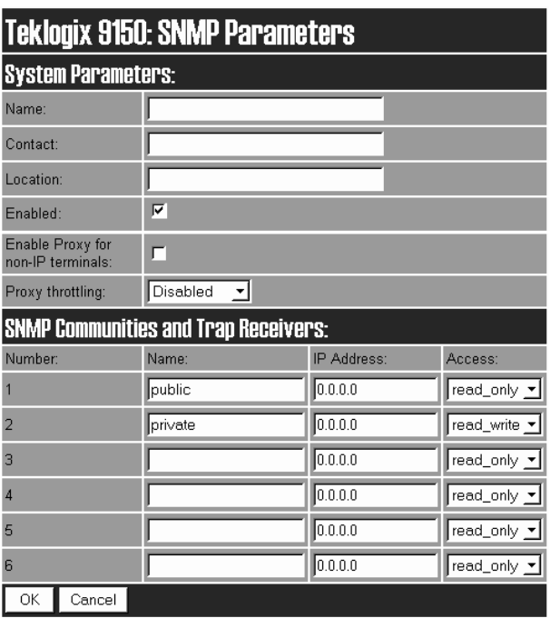
The SNMP “Configure” page, entered from the Configuration Main Menu page,
allows various network management parameters to be set or changed.
3.4.3.2 System Parameters
Name, Contact, Location
The entries in these parameters set the name, contact and location identifiers for this
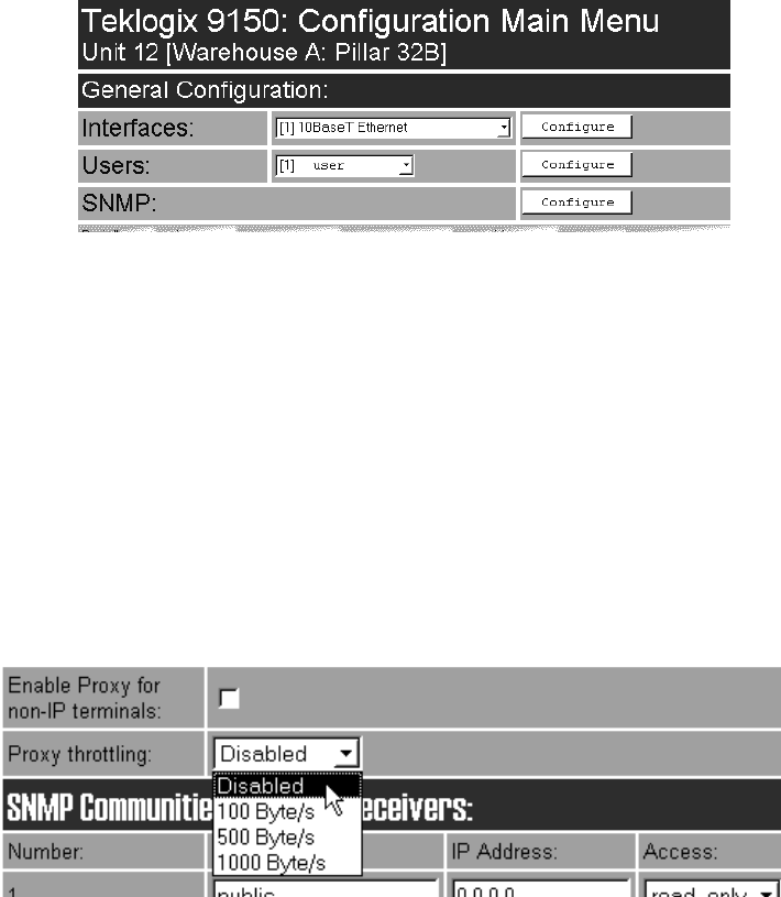
specific 9150 Wireless Gateway. The entries should be of 7-bit, US-ASCII character
type and not more than 78 characters. The name and location are then shown as the
sub-heading of each Configuration page. In the following example the identifier
appears as “Unit 12 [Warehouse A: Pillar 32B]”.
Chapter 3: 9150 Main Configuration
SNMP
42 Teklogix 9150 Wireless Gateway User Manual
Enabled
When this parameter is enabled (√), the 9150 will respond to SNMP inquiries and
provide SNMP information. For the 9150 to operate with mapRF, the checkbox
must be enabled. The default setting is enabled.
3.4.3.3 Enable Proxy for non-IP terminals
When this parameter is enabled (√), the 9150 acts as the proxy with the mapRF
manager, for terminals without IP addresses. This option should be used only when
the 9150 is acting as the Cellular Master (mini-controller).
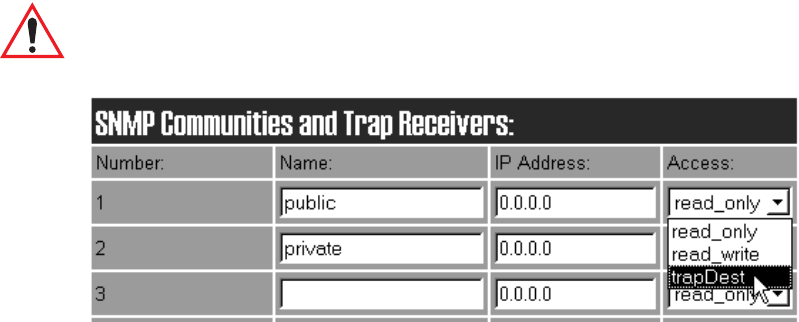
3.4.3.4 Proxy throttling
To ensure that increased radio traffic due to the 9150 acting as proxy does not create
a problem, the amount of traffic can be controlled by setting it to 100, 500, or 1000
bytes per second. The default is Disabled.
3.4.3.5 SNMP Communities and Trap Receivers
These parameter settings allow the network administrator to define the network
environment and determine the type of access allowed (read_only or read_write)
for each area name and IP address. The Name entries should be of 7-bit, US-ASCII
character type and not more than 255 characters. The trapDest IP addresses deter-
mine which SNMP manager’s stations will receive SNMP Traps from the 9150.
Teklogix 9150 Wireless Gateway User Manual 43
Chapter 3: 9150 Main Configuration
Redundancy
The 9150 sends the “Cold Start” Trap on reboot or power up.
Important: Any parameters that are changed in the SNMP Communities and
Trap Receivers menu must also be changed in the mapRF manager.
3.4.4 Redundancy
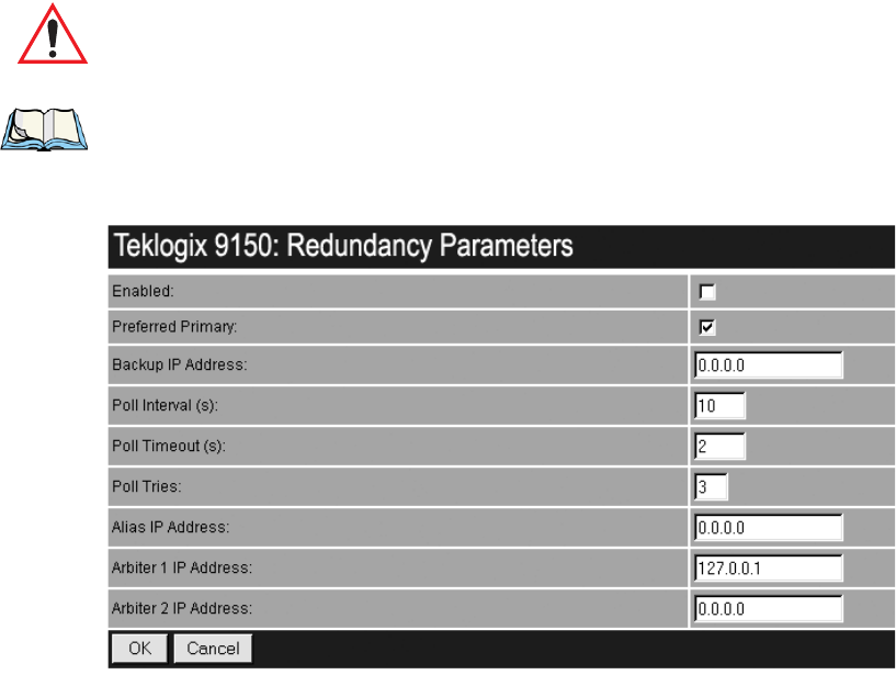
The Redundancy Parameters “Configure” page, entered from the Configuration
Main Menu page, allows the user to set various options for the redundant (backup)
operation of the 9150.
This feature enables two similarly-configured 9150s to operate in parallel. One
9150 is designated as the primary 9150, and manages communication to the rest
of the Teklogix system. The other 9150 is designated as the secondary 9150, and
remains idle. Both 9150s communicate with one or two arbiters, an extremely stable
device on the network, such as a host, which serves as a reference for the status of
the network itself.
Both the primary and secondary 9150s must be connected to the network, and each
9150 is aware of the other’s IP address. The secondary 9150 polls the primary 9150,
and the primary 9150 responds, exchanging information about their status. There
may not be more than one secondary 9150.
If the secondary 9150 cannot communicate with the primary 9150, but can commu-
nicate with one or both arbiters, it assumes that the primary 9150 is not working.
It then becomes the primary and assumes control of the Teklogix backbone on
the network.
When the first 9150 comes online again, it assumes secondary status while the
second 9150 continues as the primary. If the 9150’s cannot communicate with the
arbiter, they assume that the network is not working.
Chapter 3: 9150 Main Configuration
Redundancy
44 Teklogix 9150 Wireless Gateway User Manual
Important: Both 9150s must be configured identically, with the exception of
their unique IP addresses and the Backup IP Address parameter,
which is the IP address of the other 9150.
Note: When control of the Teklogix system is passed from one 9150 to the other,
sessions between hosts and terminals are closed, and terminals and bases
are reset.
Enabled
When this checkbox is enabled (√), the 9150 uses the Redundancy feature. A
second 9150, appropriately configured, and arbiters must be present on the network
for the feature to operate properly.
The default is disabled.
Preferred Primary
This parameter decides which 9150 becomes primary if both want to be primary.
The checkbox should be enabled (√) in only one of the redundant pair of 9150s.
The default is enabled.

Teklogix 9150 Wireless Gateway User Manual 45
Chapter 3: 9150 Main Configuration
Redundancy
Backup IP Address
The Backup IP Address parameter contains the address of the other 9150 with which
this 9150 communicates. The default value is 0.0.0.0.
Note: The Backup IP address cannot be the same as the Alias IP address
(page 46).
Poll Interval, Poll Timeout And Poll Tries Parameters
The next three parameters are closely related. When this 9150 acts as the secondary
device, it polls the primary 9150 at intervals specified by the Poll Interval parameter.
After each poll, this 9150 waits for a reply for the length of time specified by the
Poll Timeout parameter. If there is no reply during this time period, the 9150 sends
another poll to the other 9150. The total number of polls sent while this 9150 waits
for the response is specified by the Poll Tries parameter. If no response is received to
the polls, the 9150 then pings the arbiter(s) to determine the status of the network.
Poll Interval
This parameter contains the interval, in seconds, at which this 9150 communicates
with the other 9150.
The range of values is 1 to 9999, the default is 10.
Poll Timeout
This parameter contains the interval, in seconds, during which this 9150 waits for a
reply after sending a poll to the other 9150. If there is no reply, it sends another poll
to the other 9150.
The range of values is 1 to 9999, the default is 2.
Poll Tries
This parameter contains the number of times this 9150 will re-send a poll to the
other 9150, before assuming that it cannot be reached.
The usable range of values is 2 to 7, the default is 3. The value can go as high as 9.

Chapter 3: 9150 Main Configuration
Redundancy
46 Teklogix 9150 Wireless Gateway User Manual
Alias IP Address
This parameter contains the alias IP address, identical for both this and the other
9150 in the redundancy system. The primary 9150 presents the alias IP address to
the network, as well as its own unique IP address. The secondary 9150 only presents
its unique IP address to the network.
When the secondary 9150 becomes the primary, it starts to use the alias IP address
as well as its unique address, while the other 9150 stops using the alias IP address.
Wireless devices in the system which communicate directly with the Teklogix
network controller’s IP address, such as terminals using TCP Direct, may communi-
cate with the alias IP address. They will then communicate with whichever of the
two redundant 9150s is the primary.
This address must be the same on both the primary and secondary 9150.
The default address is 0.0.0.0.
Note: The Alias IP address cannot be the same as the Backup IP address
(page 45).
Arbiter 1 IP Address
This parameter contains the address of a device on the network which is known to
be reliable. Both 9150s ping this device; if they receive no reply, they ping Arbiter 2
if so configured (see page 46), otherwise they assume that the network is not operat-
ing. This address should be the same on both the primary and secondary 9150s.
Arbiter 1 must always be configured when Redundancy is enabled. The default
value is the loop-back address 127.0.0.1.
Arbiter 2 IP Address
This parameter contains the address of an optional second device on the network
which is known to be reliable. Both 9150s ping this device if they receive no reply
from Arbiter 1. If they receive no reply from Arbiter 2, they assume that the network
is not operating. This address should be the same on both the primary and secondary
9150s. If the default address is configured, Arbiter 2 won’t be used in the protocol.
The default address is 0.0.0.0.
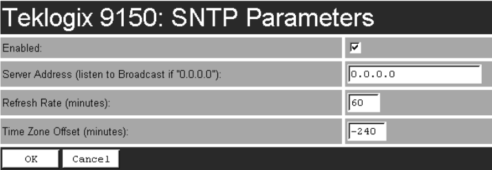
Teklogix 9150 Wireless Gateway User Manual 47
Chapter 3: 9150 Main Configuration
SNTP
3.4.5 SNTP
SNTP (Simple Network Time Protocol) is the protocol that enables the network to
maintain an accurate system time. The SNTP Parameters “Configure” page, entered
from the Configuration Main Menu page, allows the user to set the options.
Enabled
When this checkbox is enabled (√), the 9150 automatically sends requests to the
SNTP server to retrieve the time in GMT (Greenwich Mean Time) format. The 9150
then sets the current local time using the Time Zone Offset value (see page 47).
The default is enabled.
Server Address
This parameter contains the IP address of the SNTP server. If the server address is
specified, the 9150 sends unicast messages to the server to retrieve the time. If the
address is not specified (i.e. 0.0.0.0.), the 9150 retrieves the broadcast messages.
The default value is 0.0.0.0.
Refresh Rate
This parameter contains the interval, in minutes, at which the 9150 retrieves
the time. The range of values is 1 to 1440 minutes. The default value is 60.
Time Zone Offset
The Time Zone Offset is the difference between the GMT and the local time where
the 9150 is located. If you are not sure of your time zone offset, you can get the
GMT by using the console command “ ?T ” five minutes after booting up the 9150.
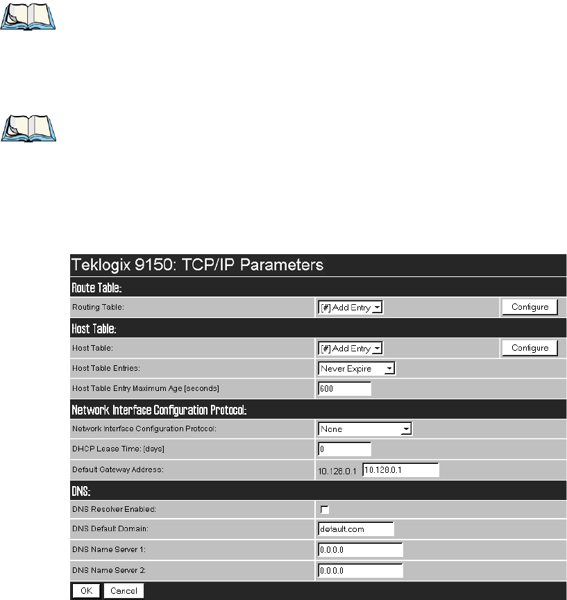
Chapter 3: 9150 Main Configuration
TCP/IP Parameters
48 Teklogix 9150 Wireless Gateway User Manual
The 9150 will retrieve the GMT and you can determine the offset value.
The range of values is -1339 to 1339 minutes. The default value is -240.
(This default represents Eastern Standard Time, Canada, with Daylight Saving.)
Note: The 9150 does not automatically compensate for Daylight Saving time.
3.4.6 TCP/IP Parameters
If the 9150 is situated on a wired network, it uses TCP/IP. A Routing Table, Host
Table, DHCP, Bootp, and DNS options are available to resolve IP addressing issues.
Note: The term host in this context refers to any device with an IP address,
including parts of the Teklogix system such as controllers, the 9150, and
associated base stations.
This use of host is common in the networking field. It should be
distinguished from Psion Teklogix’s use of host versus terminal.

Teklogix 9150 Wireless Gateway User Manual 49
Chapter 3: 9150 Main Configuration
TCP/IP Parameters
3.4.6.1 Route Table
Routing Table
The routing table is used when the 9150 and the host are not connected directly on a
single physical network segment.
Packets are routed between network segments to the network connections,
depending on the packets’ destination addresses and on the contents of the 9150’s
Host and Routing tables.
To add an entry to the 9150’s routing table, select “Configure” beside “[#] Add
Entry” in the listbox. This will open the New Routing Table Entry menu.
New Routing Table Entry
Entry Name
This is the designated name of the entry.
Destination Type
Select a destination type for this entry from the drop-down list, either Host or Net.
Router IP Address
Enter the router’s IP address in this textbox. This device must be on the same subnet
as the 9150, and must be capable of sending packets to the host. If the host is on
the same subnet as the 9150, enter its address here and in the Destination IP
Address textbox.
Destination IP Address
Enter the IP address of the host. If the host is on the same subnet as the 9150, enter
its address here and in the Router IP Address textbox.
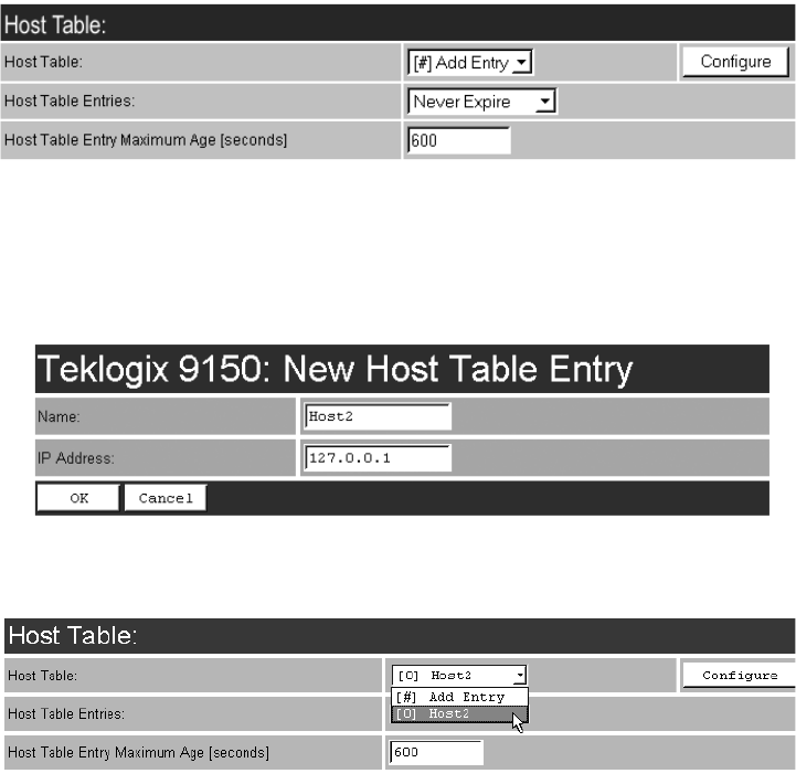
Chapter 3: 9150 Main Configuration
TCP/IP Parameters
50 Teklogix 9150 Wireless Gateway User Manual
3.4.6.2 Host Table
If no external DNS server is available, the 9150 may resolve host names to IP
addresses using its internal host table.
Host Table
Hosts are added to the table by selecting “Configure” beside “[#] Add Entry” in the
listbox. This will open the New Host Table Entry menu where a new host name and
IP address can be entered.
An existing host’s name and IP address may be edited in the Host Table Entry menu
by selecting “Configure” beside the host name in the listbox.
The host may also be deleted from the table. When choosing to delete a host, you
will be prompted for confirmation of the deletion, which will give you the opportu-
nity to cancel the action.