QUANSHENG ELECTRONICS TG-45UV Two Way Radio User Manual
Fujian Nanan Quansheng Electronics Co., Ltd. Two Way Radio
user manual

USER'S MANUAL
Two way radio
TG-45UV
FCC ID:XBPTG-45UV

PRECAUTIONS BEFORE USING
Please read the User's Manual before using. It gives you important information about how
to operate the portable radio.
Please put the radio and accessories where the children can not touch.
Maintenance can only be performed by professional technicians.
Please use the standard battery pack and charger in order not to destroy the radio.
Please use the standard antenna,in order not to shorten the distance.
Do not expose the radio to sunlight for a long period of time, nor put it near the heat, nor
use it in a high temperature environment.
Do not put it in extreme dust nor wet or on unsteady surfaces.
Keep it dry. (Rain or moisture will erode the electronic board).
Do not transmit when the antenna is not installed.
If you find bad smell or smog,please turn off the radio immediately.And take the battery off
the radio,then contact with QS agent.
Thank you for purchasing this Radio.
We believe this easy-to-use radio will provide reliable and
dependable communication.
QS Radio incorporates the latest advanced technology.
As a result, we know that you will be pleased with the quality
and features of this product.
45UV

CONTENTS
FEATURES
UHF/VHF dual band receive/transmit
FM radio (65-108MHz)
Large LCD display
High capacity Li-ion battery and smart charger
PC programmable
Fast MENU operation
Emergency alarm function
Squelch level adjustable
Multi power saving function
Voice prompt(Chinese or English)
Reminding switch
Dual display of frequency and channel
Channel name edit
Channel storing
Frequency/Channel mode shift
Multi LCD backlight selective
Time of backlight auto off selective
VOX function
Dual-watch operation
Receive/Transmit code setting separately
Cable clone
CTCSS/DCS code search automatically
Frequency deviation and offset direction
setting
Multi step frequency
Busy channel lock
Time-out-timer(TOT)
Multi display mode: channel/channel-frequency/
channel name
Multi scan function selective
Channel scan additive
Main/Sub channel shift
1750Hz call tone
Reminding of repeater transfer
Auto-keylock
128 channels
Channel delete function
Reset
DTMF function
PTT-ID
CTCSS/DCS
Reverse function
Stun/Kill/Revive
Single call/Group call/Troop call
01
02
02
03
04
04
05
06-07
08
09
09
09
10-12
13
14-22
23
23
SUPPLIED ACCESSORIES
READY TO WORK
CHARGING NOTES (1)
CHARGING NOTES (2)
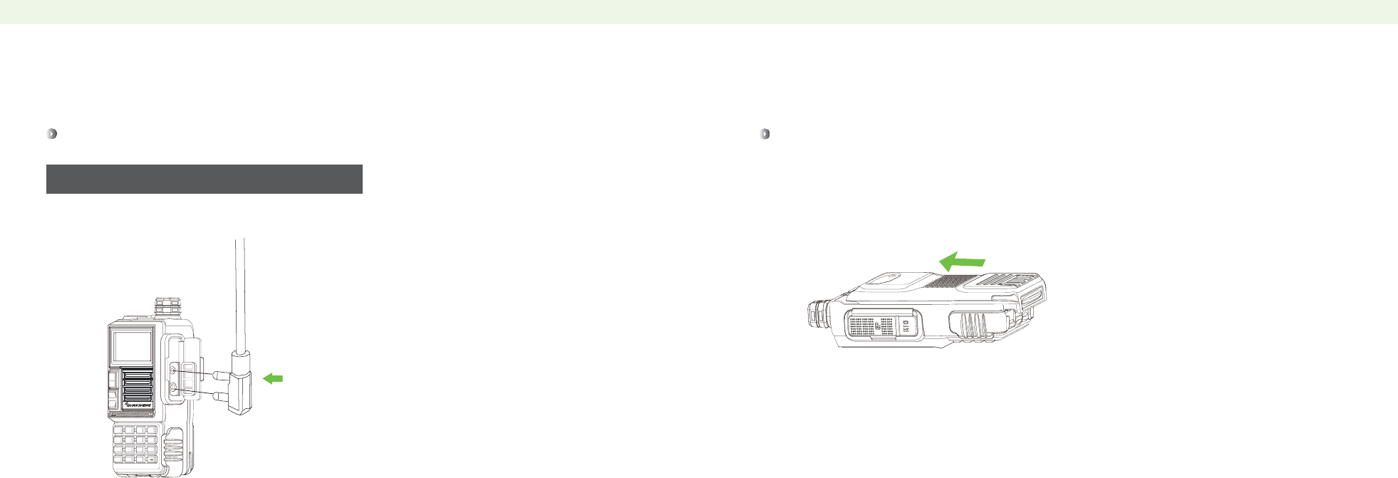
INSTALLING ANTENNA
INSTALLING BELT CLIP
INSTALLING EXTERNAL SPEAKER/MICROPHONE
ATTACHING THE BATTERY PACK
DIAGRAM
BASIC OPERATION
LCD DISPLAY
LCD ICON EXPLANATION
SHORTCUT KEYS
MENU FUNCTIONS
FAST MENU OPERATION FLOW
FUNCTION OPERATION AND DESCRIPTION
SQUELCH LEVEL(SQL)

32
32
33
33
34
34
35
35
36
36-37
38
38
39
39
40
40
41
SCAN RESUMED MODE
PTT ID(PTT-ID)
PTT ID PROLONG TIME(PTT-LT)
A CHANNEL DISPLAY MODE(MDF-A)
B ChANNEL DISPLAY MODE(MDF-B)
BUSY CHANNEL LOCK(BCL)
AUTO KEYPAD LOCK(AUTOLK)
FREQUENCY OFFSET DIRECTION SETTING(SFT-D)
FREQUENCY DEVIATION(OFFSET)
CHANNEL STORE (MEM-CH)
CHANNEL DELETE(DEL-CH)
STANDBY BACKLIGHT(WT-LED)
RX BACKLIGHT(RX-LED)
TX BACKLIGHT(TX-LED)
ALARM MODE(AL-MOD)
OPTIONAL SIGNAL (OPTSIG)
MUTE MODE SELECTION (SPMUTE)
23
24
24
25
26
26
27
27
28
28
29
29
30
30
31
31
STEP FREQUENCY(STEP)
OUTPUT POWER (TXP)
BATTERY SAVING (SAVE)
VOX FUNCTION (VOX)
AUTO BACKLIGHT (ABR)
DUAL-WATCH OPERATION (TDR)
KEYPAD SOUND REMINGDING (BEEP)
TIME-OUT-TIMER (TOT)
RECEIVING DCS (R-DCS)
RECEIVING CTCSS (R-CTCS)
TRANSMITTING DCS (T-DCS)
TRANSMITTING CTCSS (T-CTCS)
VOICE REMINDING (VOICE)
ANI-ID (ANI-ID)
DTMFST(DTMFST)
SIGNAL CODE (S-CODE)
CONTENTS CONTENTS

48
48
49
49
50
50
51-52
52-56
57
58-59
60
REVERSE FUNCTION( R )
FREQUENCY SCANNING
CHANNEL SCANNING
AUTOMATIC SEARCH FM RADIO(FM)
SEARCH CTCSS/DCS CODE
CURSOR“▲” CONVERSION(A/B)
STUN/KILL/REVIVE
SINGLE CALII/GROUP CALL/TROOP CALL
CTCSS TABLE LIST
DCS TABLE LIST
SPECIFICATONS
41
42
42
43
43
44
44
45
45
45
46
46
47
47
47
47
47
TAIL TONE ELIMINATION(STE)
TAIL TONE ELIMINATION WHEN THROUGH REPEATER(RP-SET)
DELAY TIME OF TAIL TONE ELIMINATION WHEN THROUGH REPEATER(RPT-RL)
DISPLAYS WHEN POWER ON(PONMSG)
CALL END WARNING TONE(ROGER)
DUAL-WATCH OPERATION(TDR-AB)
RESET(RESET)
VFO-MENU INITIALIZATION
ALL-MENU AND CHANNEL INITIALIZATION
MANUALLY LOCK THE KEYPADS
FM RADIO(FM)
RAPID ALERT(ALARM)
JACKLIGHT
MONITOR(MON)
CABLE CLONE(COPING)
CHANNEL/FREQUENCY MODE CONVERSION(VF0/MR)
TX 1750Hz CALL TONE
CONTENTS CONTENTS

Battery packs are not charged when they are shipped, charge them before use.
Initially charging the battery pack after purchase or extended storage (longer than 2 months) will
not bring the battery pack to its greatest capacity or its normal capacity, which can be done only
after repeatedly charging and discharging for two or three times.
CHARGING NOTES (1)
ʎ
ʎ
ʎ
After the battery is charged to its highest capacity, don’t charge anymore, and
remove it from the charger. Otherwise it will affect the life of the battery.
Do not short-circuit the battery terminals or throw the battery into fire.
Never attempt to remove the casing from the battery pack.
!
Please turn the power off before charging. It will affect the battery life when charging the
power-on radio.
If the radio still shows low power after the normal charge, please change a new battery.
The average usage time of battery pack is 13 hours. Average usage time is 5% for transmitting,
5% for receiving and 90% for standby.
01 02
SUPPLIED ACCESSORIES
STANDARD SUPPLIED ACCESSORIES
STANDARD SUPPLIED ACCESSORIES
Carefully unpack the portable radio. We suggest that you check the following
items before you throw away the packing materials.
Antenna Li-ion Battery (7.2V) Belt Clip
Adapter User's Manual
Charger
Portable radio
Antenna
Li-ion battery (7.2V)
Belt clip
charger
Adapter
User's manual
1
1
1
1
1
1
1
ITEM QTY
USER'S MANUAL
READY TO WORK READY TO WORK
The radio is not fully rain resistant while using the
external speaker/microphone.
ʎ
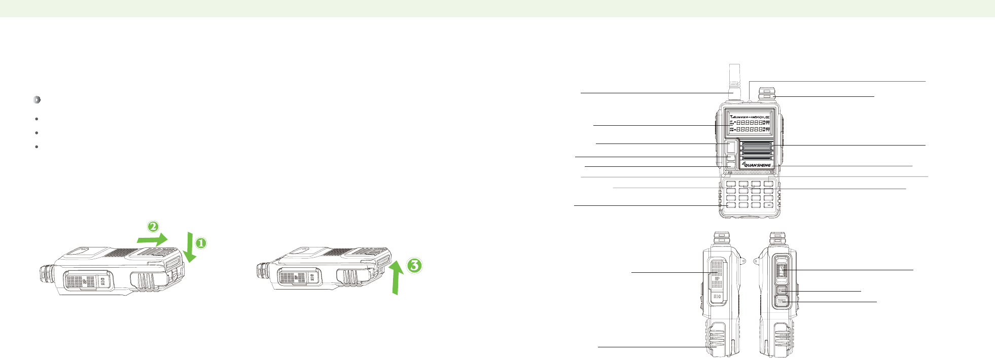
ATTACHING THE BATTERY PACK
INSTALLING EXTERNAL SPEAKER/MICROPHONE
Insert the speaker/microphone plugs into the speaker/microphone jacks. Slide the battery pack into the back of the radio in the direction of the arrow(①), then lock it
with the battery release button. Slide the battery pack until the battery release button makes a
"clicking" sound.
05 06
MENU EXIT
^
^
1STEP 2TXP 3SAVE
0SQL
6ABR
5WN
7TDR
4VOX
8BEEP 9TOT #
*SCAN
BAND
A/B
VFO
MR
READY TO WORK DIAGRAM
DIAGRAM
Turn off the radio before releasing the battery pack.
Push the battery release button in the direction of the arrow(①)as shown below.
At the same time push the battery back.
The battery pack is then released.
RELEASING THE BATTERY PACK
BAND key
Indicator
Menu/Confirm key
keypad
Antenna
LCD display
VFO/MR key
A/B key
Sp/Mic/Programming
Jacks
Battery pack
Microphone
Exit key
Up/Down key
Speaker
Jacklight
Power/Volume switch
PTT switch
Jacklight/Monitor switch
FM radio/Alarm Key
07 08
MENU EXIT
^
^
1STEP 2TXP 3SAVE
0SQL
6ABR
5WN
7TDR
4VOX
8BEEP 9TOT
*
#
SCAN
VFO
MR
A/B
BAND
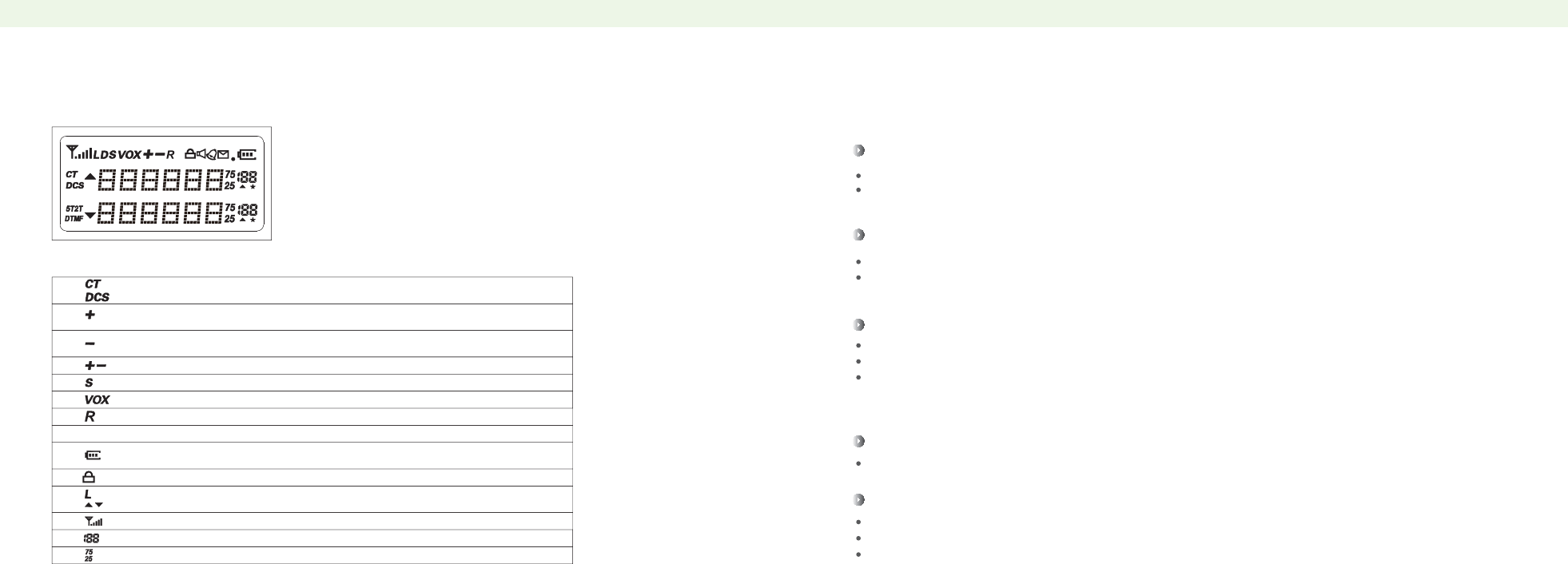
LCD DISPLAY
LCD ICON EXPLANATION
This symbol will appear when transmitting, it means transmitting CTCSS code.
This symbol will appear when transmitting, it means transmitting DCS code.
BASIC OPERATION
PTT Key
Transmitting/Receiving switch key: Press "PTT" to transmit and speak to microphone.
Release "PTT" to receive.
CALL Key (FM/Alarm)
Press it for a short time to turn on FM radio function.Operate it again to turn it off.
Press it for a long time to turn on Alarm function.Operate it again to turn it off.
MON Key (Jacklight/Monitor)
Press it for a short time to turn on Jacklight. Operate it again to turn it off.
Press it for a long time to turn on Monitor function.
Press Jacklight/Monitor key and turn the power on, to enter channel clone condition, it can copy one
radio's channel parameters to another one. Cloning cable must be used to connect these two radios.
Band Key
UHF/VHF frequency band shift;
FM radio 65-75/76-108MHz shift;
In transmitting mode, press Band key to send 1750Hz call tone.
LCD Display
Display all the working condition.
In frequency mode, this symbol will appear, it means transmitting frequency equals
receiving frequency plus the offset frequency. It can set different frequencies.
In frequency mode, it will appear this symbol, it means transmitting frequency equals
receiving frequency minus the offset frequency. It can set different frequencies.
It means the transmitting and receiving frequencies are different at current channel.
It means it already set dual watch operation function.
VOX function
Reverse function
It represents the remaining battery. when the battery is almost used up,the frame
starts to flicker and it forbids to transmit.
It means the keypad is locked, pressing key #/Lock can unlock the keypad.
Low output power.
Current frequency and current menu setting.
Signal strength.
Channel number display
Frequency ending display
09 10
BASIC OPERATION BASIC OPERATION
BASIC OPERATION
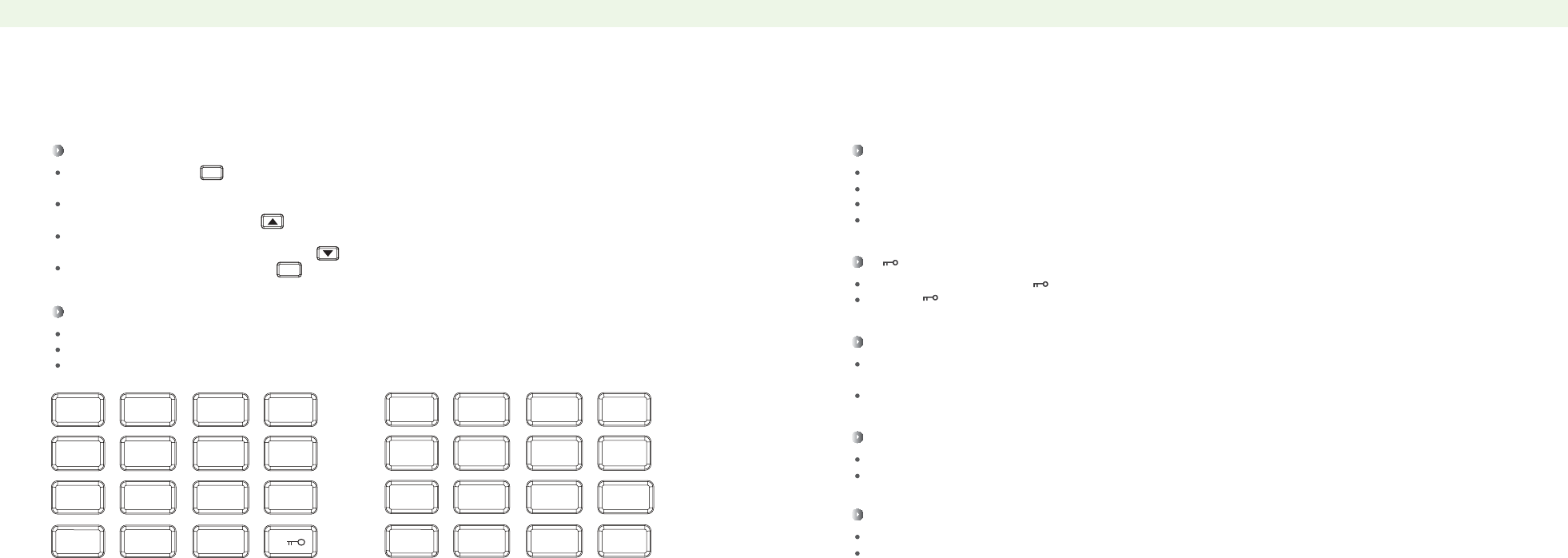
Function Keypads
Menu/Confirm key:
It’s used for activating the menu, choose each menu item and confirm the parameter.
Up key (Press more than 2s, the channel and frequency will move upward rapidly; In scannig, press
Up key to upward scanning.):
Down key (Press more than 2s, the channel and frequency will move downward rapidly; In scannig,
press Up key to downward scanning):
Press key Exit to exit and clear:
Number Keypads
Input the information to the radio.
Input the non-standard CTCSS code in non-standard mode.
In transmitting mode, press number keys to send corresponding DTMF code.
MENU
EXIT
BASIC OPERATION
*SCAN Key
Press Scan key for a short time to activate RX/TX reverse function.
Press Scan key for more than 2s to start frequency or channel scanning.
In FM radio mode, press Scan key to automatically search FM stations.
In CTCSS/DCS mode, press Scan key to start CTCSS/DCS code scanning.
Indicator
Transmitting: the red light glitter
Receiving: the green light glitter
Sp/Mic/Programming Jacks
It’s used for external speaker/microphone.
It’s used to connect cable for computer programming or application upgrade.
# Key
In channel mode, press # for a short time to switch H/L output power.
Press # key for more than 2 seconds to lock or unlock the keypad.
Power/Volume Switch
Turn the Power/Volume switch clockwise to turn the power on.
Turn the Power/Volume switch counter-clockwise to turn the power off.
Turn the Power/Volume switch clockwise to volume up, otherwise it’s volume down.
11 12
SCAN
MENU EXIT
^
^
1STEP 2TXP 3SAVE
0SQL
6ABR
5WN
7TDR
4VOX
8BEEP 9TOT #
*
ABCD
123*
4560
789#
MENU FUNCTIONS
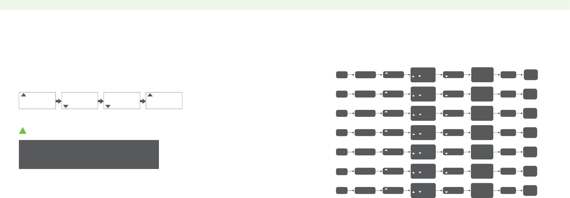
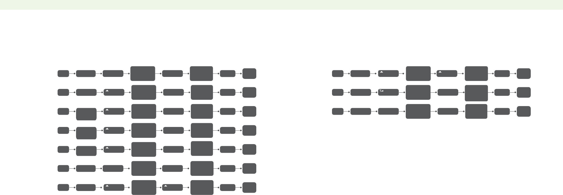
FAST MENU OPERATION FLOW
FAST MENU SETTING FAST MENU OPERATION FLOW
1
2
3
4
5
6
0
No. Feature
Function
Characterr
Function Set LCD Display Parameter LCD Display
Confirm key
Selectable Back Key
Page
P22
P23
P24
P24
P25
P25
P26
Menu No.
Menu
Parameter
Menu No.
Menu
Parameter
Menu No.
Menu
Parameter Setting
Menu No.
Menu
Parameter Confirm
ʎ
① In channel mode, the setting of following features is invalid:
CTCSS/DCS, Wide/Narrow bandwidth, PTT-ID.
Busy channel lock, Channel scan additive, Channel name edit.
② High/Low power can only be changed by pressing fast key #.
!
NOTE
Squelch
Level
Step
Frequency
Output
Power
Battery
Saving
VOX
Channel
Bandwidth
Auto
Backlight
PTT/
EXIT
PTT/
EXIT
PTT/
EXIT
PTT/
EXIT
PTT/
EXIT
PTT/
EXIT
MENU
MENU
MENU
MENU
MENU
MENU
PTT/
EXIT
MENU
MENU+0
MENU+1
MENU+3
MENU+4
MENU+5
MENU+6
MENU+2
0-9 levels
0:Lowest
9:Highest
2.5/5.0/6.25
/10.0/12.5/
25.0KHZ
OFF:OFF
1:1 2:2
3:3 4:4
HIGH: 6W
LOW: 1W
OFF: OFF
10: Lowest
Sensitivity
1: Highest
Sensitivity
W: 25.0K
N: 12.5K
OFF:1-5s
0
SQL
5
1
STEP
20.5K
2
TXP
HIGH
3
SAVE
1
4
VOX
OFF
5
WN
WIDE
6
ABR
OFF
0
SQL
6
1
STEP
12.5K
2
TXP
LOW
3
SAVE
2
4
VOX
9
5
WN
NARR
6
ABR
NARR
SQL
STEP
TXP
SAVE
VOX
W/N
ABR
1 Press Menu key;
2 Press Menu key again;
3 Press Up/Down key to select Menu No.
4 press Menu to confirm or EXIT key to exit(As picture below).
Press Menu key,
and then press
or key to
choose.
Press Menu key,
and then press
or key to
choose.
Press Menu key,
and then press
or key to
choose.
Press Menu key,
and then press
or key to
choose.
Press Menu key,
and then press
or key to
choose.
Press Menu key,
and then press
or key to
choose.
Press Menu key,
and then press
or key to
choose.
13 14

No. Feature
Function
Characterr
Function Set LCD Display Parameter LCD Display
Confirm key
Selectable Back Key
Page
No. Feature
Function
Characterr
Function Set LCD Display Parameter LCD Display
Confirm key
Selectable Back Key
Page
FAST MENU OPERATION FLOW
8
9
10
11
12
13
7 P26
P27
P28
P27
P28
P29
P29
Dual-watch
Operation
Keypad
Sound
Reminding
Time-Out-
Timer
Receive
DCS
PTT/
EXIT
PTT/
EXIT
PTT/
EXIT
PTT/
EXIT
PTT/
EXIT
PTT/
EXIT
MENU
MENU
MENU
MENU
MENU
MENU
PTT/
EXIT
MENU
MENU+7
MENU+8
MENU+10
MENU+11
MENU+12
MENU+13
MENU+9
ON
OFF
O
OFF
OFF
D023N-D754N
D023I-D754I
15,30……
600s
OFF
67.0-254.1HZ
OFF
D023N-D754N
D023I-D754I
OFF
67.0-254.1HZ
7
TDR
OFF
8
BEEP
OFF
9
TOT
15
10
R-DCS
OFF
7
TDR
ON
8
BEEP
ON
9
TOT
600
10
R-DCS
D023N
11
R-CTCS
OFF
12
T-DCS
OFF
13
T-CTCS
OFF
11
R-CTCS
67.0HZ
12
T-DCS
D023N
13
T-CTCS
67.0HZ
TDR
BEEP
TOT
R-DCS
R-CTCS
T-DCS
T-CTCS
Receive
CTCSS
Transmit
DCS
Transmit
CTCSS
FAST MENU OPERATION FLOW
15
16
17
18
19
20
14 P30
P30
P31
P31
P32
P32
P33
Voice
Reminding
ANI-ID
DTMFST
Signal
Code
PTT/
EXIT
PTT/
EXIT
PTT/
EXIT
PTT/
EXIT
PTT/
EXIT
PTT/
EXIT
MENU
MENU
MENU
MENU
MENU
MENU
PTT/
EXIT
MENU
MENU+14
MENU+15
MENU+17
MENU+18
MENU+19
MENU+20
MENU+16
ON
OFF
1-5 d igit arbitrary
selection(It can
be programmed
by software.)
1-15 group
(It can be
programmed
by software.)
OFF
DT-ST:Sending
by keypads
ANI-ST:Auto
sending
DT+ANI:Auto
sending and
sending by
keypads
TO:Time scanning
CO:Carrier wave
scanning
SE:Search
scanning
OFF:Press PTT not to send
BOT:Press PTTto send.(PTT
ID code can choose from
program software
EOT:Release PTT to send.
BOTH:Press or release PTT
to send.
0,1,2……
30ms
14
VOICE
OFF
15
ANI-ID
*****
16
DTMFST
OFF
17
S-CODE
1
14
VOICE
ON
15
ANI-ID
*****
16
DTMFST
DT-ST
17
S-CODE
13
18
SC-REV
TO
19
PTT-ID
OFF
20
PTT-LT
0
18
SC-REV
SE
19
PTT-ID
BOT
20
PTT-LT
1
VOICE
ANI-ID
DTMFST
S-CODE
SC-REV
PTT-ID
PTT-LT
Scan
Resumed
Mode
PTT ID
PTT ID
Prolong
Time
Press Menu key,
and then press
or key to
choose.
Press Menu key,
and then press
or key to
choose.
Press Menu key,
and then press
or key to
choose.
Press Menu key,
and then press
or key to
choose.
Press Menu key,
and then press
or key to
choose.
Press Menu key,
and then press
or key to
choose.
Press Menu key,
and then press
or key to
choose.
Press Menu key,
and then press
or key to
choose.
Press Menu key,
and then press
or key to
choose.
Press Menu key,
and then press
or key to
choose.
Press Menu key,
and then press
or key to
choose.
Press Menu key,
and then press
or key to
choose.
Press Menu key,
and then press
or key to
choose.
Press Menu key,
and then press
or key to
choose.
15 16

No. Feature
Function
Characterr
Function Set LCD Display Parameter LCD Display
Confirm key
Selectable Back Key
Page
No. Feature
Function
Characterr
Function Set LCD Display Parameter LCD Display
Confirm key
Selectable Back Key
Page
FAST MENU OPERATION FLOW
22
23
24
25
26
27
21 P33
P34
P35
P34
P35
P36
P36-37
A Channel
Display
Mode
B Channel
Display
Mode
Busy
Channel
Lock
Auto
Keypad
Lock
PTT/
EXIT
PTT/
EXIT
PTT/
EXIT
PTT/
EXIT
PTT/
EXIT
PTT/
EXIT
MENU
MENU
MENU
MENU
MENU
MENU
PTT/
EXIT
MENU
MENU+21
MENU+22
MENU+24
MENU+25
MENU+26
MENU+27
MENU+23
FREQ:Channel+
frequency
CH: Channel
NAME:Channel
name(It can be
programmed by
software.)
FREQ:Channel+
frequency
CH:Channel
NAME:Channel
name(It can be
programmed by
software.)
ON
OFF
ON
OFF
OFF
+:TX frequency
>RX frequency
-:TX frequency
<RX frequency
00.000-
69.9975MHZ
0-127
Channels
21
MDF-A
FREQ
22
MDF-B
FREQ
23
BCL
OFF
24
AUTOLK
OFF
21
MDF-A
CH
22
MDF-B
CH
23
BCL
ON
24
AUTOLK
ON
25
SFT-D
OFF
26
OFFSET
00.000
27
MEM-CH
000
25
SFT-D
ON
26
OFFSET
05.000
27
MEM-CH
036
MDF-A
MDF-B
BCL
AUTOLK
SFT-D
OFFSET
MEM-CH
Frequency
Offset
Direction
Setting
Frequency
Deviation
Channel
Store
FAST MENU OPERATION FLOW
29
30
31
32
33
34
28 P38
P38
P39
P39
P40
P40
P41
Channel
Delete
Standby
Backlight
RX
Backlight
TX
Backlight
PTT/
EXIT
PTT/
EXIT
PTT/
EXIT
PTT/
EXIT
PTT/
EXIT
PTT/
EXIT
MENU
MENU
MENU
MENU
MENU
MENU
PTT/
EXIT
MENU
MENU+28
MENU+29
MENU+31
MENU+32
MENU+33
MENU+34
MENU+30
Any one of
the stored
channels.
OFF
Green
Red
Yellow
OFF
Green
Red
Yellow
OFF
Green
Red
Yellow
SITE:Site alarm
TONE:Send
alarm tone
CODE:Send
alarm code
QT: CTCSS conform
to receive the call.
QT+DT: CTCSS
and DTMF conform
to receive the call.
QT*DT: CTCSS or
DTMF conform to
receive the call.
28
DEL-CHDEL-CH
000
29
WT-LED
OFF
30
RX-LED
OFF
31
TX-LED
OFF
28
DEL-CH
006
29
WT-LED
RED
30
RX-LED
RED
31
TX-LED
RED
32
AL-MOD
OFF
34
SPMUTE
QT QT+DT
32
AL-MOD
SITE
34
SPMUTE
DEL-CH
WT-LED
RX-LED
TX-LED
AL-MOD
SPMUTE
Alarm
Mode
Optional
Signal
Mute Mode
Selection
Press Menu key,
and then press
or key to
choose.
Press Menu key,
and then press
or key to
choose.
Press Menu key,
and then press
or key to
choose.
Press Menu key,
and then press
or key to
choose.
Press Menu key,
and then press
or key to
choose.
Press Menu key,
and then press
or key to
choose.
Press Menu key,
and then press
or key to
choose.
Press Menu key,
and then press
or key to
choose.
Press Menu key,
and then press
or key to
choose.
Press Menu key,
and then press
or key to
choose.
Press Menu key,
and then press
or key to
choose.
Press Menu key,
and then press
or key to
choose.
Press Menu key,
and then press
or key to
choose.
Press Menu key,
and then press
or key to
choose.
17 18
OPTSIG
33
OPTSIG
DTMF
33
OPTSIG
DTMF
ON
OFF

No. Feature
Function
Characterr
Function Set LCD Display Parameter LCD Display
Confirm key
Selectable Back Key
Page
No. Feature
Function
Characterr
Function Set LCD Display Parameter LCD Display
Confirm key
Selectable Back Key
Page
FAST MENU OPERATION FLOW
36
37
38
39
40
35 P41
P42
P43
P42
P43
P44
P45
Tail Tone
Elimination
Repeater
Tail Tone
Elimination
Time of
Repeater
Tail Tone
Elimination
Displays
When Power
On
Reminding
of End
Talk
PTT/
EXIT
PTT/
EXIT
PTT/
EXIT
PTT/
EXIT
PTT/
EXIT
Auto
MENU
MENU
MENU
MENU
MENU
Auto
PTT/
EXIT
MENU
MENU+35
MENU+36
MENU+38
MENU+39
MENU+40
Press key
“#”for
more than 2s.
MENU+37
ON
OFF
OFF
1,2…10ms
FULL:Full
frequency
character
MSG:Display
of NUT logo
OFF
1,2…10ms
ON
OFF
Repeatedly press
key“#”for more
than 2s to lock
or unlock.
35
STE
OFF
36
RP-STE
OFF
37
RPT-RL
OFF
38
PONMSG
OFF
35
SIT
CH
36
RP-STE
5
37
RPT-RL
5
38
PONMSG
MSG
39
ROGER
FULL
40
TDR-AB
OFF
39
ROGER
ON
40
TDR-AB
A
STE
RP-STE
RPT-RL
PONMSG
ROGER
TDR-AB
Dual-watch
Operation
(Cross Band
TX/RX)
Manually
Lock the
Keypads
400.875
136.225
400.875
136.225
FAST MENU OPERATION FLOW
P46
P46
P47
P47
P47
P47
FM Radio
Rapid
Alert
Jacklight
Monitor
PTT/
CALL
PTT
Auto
Auto
Auto
Auto
Auto
Auto
Auto
Auto
AutoAuto
Slightly
press
Call key
Press CALL
key for more
than 2s.
Press key
MON for more
than 2s.
Press key
MON for more
than 2s.
Press the
VFO/MR key.
Tap MON
key
MR/VFO65-
75MHZ
76-108MHZ
65-108MHZ
Press key MON
for more than 2s
to turn it on.
Release key MON
to turn it off
.
Repeatedly
tap MON key
to turn Jackight/
Warning light off.
Display channel
mode according
to menu21 and
22.
FM
100.700
ALARM
138.625
COPING
400.875
136.225
400.875
136.225
FM
ALARM
MON
COPING
VFO/MR
Cable
Clone
Channel /
Frequency
Mode
Conversion
3
4
Press Menu key,
and then press
or key to
choose.
Press Menu key,
and then press
or key to
choose.
Press Menu key,
and then press
or key to
choose.
Press Menu key,
and then press
or key to
choose.
Press Menu key,
and then press
or key to
choose.
Press Menu key,
and then press
or key to
choose.
Press Menu key,
and then press
or key to
choose.
41 P44
PTT/
EXIT
MENUMENU+41
VFO:Menu
initialization
ALL:Menu
and channel
initialization
41
RESET
ALL
41
RESET
VFO
RESET
Reset
Press Menu key,
and then press
or key to
choose.
Press BAND key,
and then press▲
or▼key to choose,
or it can input
numbers directly.
19 20
OFF
A band transmit
(Upper row
frequency)
A band transmit
(Bottom row
frequency)
No. Feature
Function
Characterr
Function Set LCD Display Parameter LCD Display
Confirm key
Selectable Back Key
Page
P47
Release
PTT
Auto
Press key
PTT+BAND
TX 1750Hz
Call Tone
FAST MENU OPERATION FLOW
P50
Auto
Auto
Repeatedly
press key“#” H:6W
L:1W
H/L
High/Low
Power Fast
Conversion
400.875
136.225
3
4
400.875
136.225
3
4
Repeatedly
press key“#”
P48
P48
P49
P49
P50
P50
Reverse
Function
Frequency
Scanning
Channel
Scanning
Auto
Search FM
Radio
Auto
PTT/
EXIT
PTT/
CALL
PTT/
EXIT
Auto
Auto
Auto
Auto
MENU
Auto
PTT/
EXIT
Auto
Tap“ ”key
In frequency
mode, press
key“ ”for
more than 2s.
MENU+10
or MENU+11
Tap key “AB”
In channel
mode, press
key“ ”for
more than 2s.
In FM Radio
mode, press
key“ ”.
Repeatedly tap
key“ ”to
turn it on or off.
Scan upward
or downward
according to
the set step
frequency.
FM Radio
band:
65-108MHz.
Scan upward
or downward
according to
the set
channels.
Automatcally
research
CTCSS/
DCS code.
A(Upper row)/
B(Bottom row)
R-CTCS
or R-DCS
R
A/B
FM
FM
Research
CTCSS/DCS
Code
Cursor "▲"
Conversion
400.875
136.225
400.875
136.225
400.875
136.225
3
4
400.875
136.225
3
4
400.875
136.225
3
4
FM
100.700
Press key ▲or▼
to change the
scanning direction.
Press key ▲or▼
to change the
scanning direction.
Repeatedly
press key
“ ”.
Press“ ”
key
Repeatedly
press key
“AB”
*
*
*
**
**
No. Feature
Function
Characterr
Function Set LCD Display Parameter LCD Display
Confirm key
Selectable Back Key
Page
FAST MENU OPERATION FLOW
P51-52
P52-56
STUN
KILL
REVIVE
SINGLE CALII
GROUP CALL
TROOP CALL
Auto
Auto
PTT+Remote
code
Stun:only receive
without transmit.
Kill:receive and
transmit forbidden.
Revive: activate it
back to normal use.
400.875
136.225
21 22

FUNCTION OPERATION AND DESCRIPTION(The following description is without
voice prompt.)
Auto Backlight(ABR)——Menu No.6
1. In frequency or channel mode, press Menu+6, the LCD displays:
2. Press key Menu, and then press key ▲ or ▼ to choose the backlight display time(1-5s). The LCD
displays:
3. After setting, press key Menu to confirm, and then press key PTT or Exit to standby.
This function can adjust the auto off time after radio display backlight is on.
The operation steps are as follows:
We suggest you set 4-5 levels.
ʎ
!
NOTE
!
NOTE
In dual-watch operation mode, you can change the parameter of AB channel or frequency freely.
ʎ
Dual-watch Operation(TDR)——Menu No.7
1. In standby mode, press Menu+7, the LCD displays:
2. Press key Menu, and then press key ▲ or ▼ to choose ON, the LCD displays:
3. After setting, press key Menu to confirm, and then press key PTT or Exit to standby.
The LCD displays:
When this function is on, you may receive the signal of channel A and channel B at the same time.
If any AB channel or frequency receives signal, “▲” will glitter on corresponding channel or
frequency.Example:Channel A: 460.125MHz,Channel B: 151.235 MHz ,The LCD displays:
or
The operation steps are as follows:
FUNCTION OPERATION AND DESCRIPTION(The following description is without
voice prompt.)
VOX Function(VOX)——Menu No.4
1. In frequency or channel mode, press Menu+4, the LCD displays:
2. Press key Menu, and then press key ▲ or ▼ to choose VOX level. The LCD displays: There
are (OFF-10) levels. OFF:OFF 10: Lowest level 1: Highest level
3. After setting, press key Menu to confirm, and then press key PTT or Exit to standby. The LCD
displays:
When this function is on, the system will recognize your talking to the microphone and then it will
automatically shift to transmitting mode without manual operation (This function is useful for
earphone users).
The operation steps are as follows:
!
NOTE
The higher level is, the higher sensitivity of microphone is.This function is invalid
in scanning and FM radio mode.
ʎ
4
VOX
OFF
4
VOX
5
400.875
136.225
VOX
6
ABR
OFF
6
ABR
3
3460.125
151.235 4
460.125
151.235
7
TDR
OFF 7
TDR
ON
3460.125
151.235
4
S
25 26

FUNCTION OPERATION AND DESCRIPTION(The following description is without
voice prompt.)
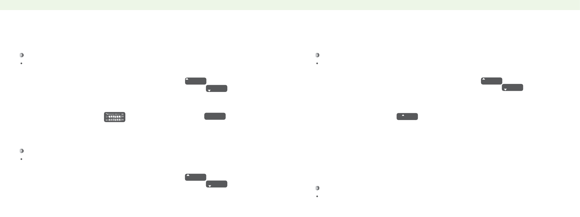
Squelch Level(SQL)——Menu No.0
1. In frequency or channel mode, press Menu+0, the LCD displays:
2. Press key Menu, the LCD displays:
3. Press key ▲ or ▼ to choose squelch level.There are 0-9 levels. 0: Lowest 9: Highest
4. After setting, press key Menu to confirm, and then press key PTT or Exit to standby.
This function can turn on or off the monitor according to signal strength.
The operation steps are as follows:
!
NOTE
Too high squelch level may result in failing to receive in weak signals,Too low squelch level will
make it be disturbed by other signals.
ʎ
!
NOTE
In channel mode, this function is invalid.
ʎ
Step Frequency(STEP)——Menu No.1
1. In frequency mode, press Menu+1, the LCD displays:
2. Press key Menu, the LCD displays:
3. Press key ▲ or ▼ to choose your desired step frequency.You can set 2.5/5.0/6.25/10.0/12.5/
25.0KHz step frequency.
4. After setting, press key Menu to confirm, and then press key PTT or Exit to standby.
This function can choose the step frequency you want to set.
The operation steps are as follows:
FUNCTION OPERATION AND DESCRIPTION(The following description is without
voice prompt.)
Output Power(TXP)——Menu No.2
1. In frequency or channel mode, press Menu+2, the LCD displays:
2. Press key Menu, the LCD displays:
3. Press key Menu, and then press key ▲ or ▼ to choose.High: 6W,Low: 1W,
4. After setting, press key Menu to confirm, and then press key PTT or Exit to standby.
This function can choose High/Low output power.
The operation steps are as follows:
!
NOTE
Selecting high output power can improve the call quality, low output pow can reduce radiation and the
battery capacity loss. In channel mode, press fast key "#" to switch between high and low output power.
ʎ
!
NOTE
If you choose OFF, the radio is not battery saving. In general, we suggest you choose 1:1.
ʎ
Battery Saving(SAVE)——Menu No.3
1. In frequency or channel mode, press Menu+3, the LCD displays:
2. Press key Menu, and then press key ▲ or ▼ to choose battery saving function. The LCD displays:
There are five kinds of mode. ①OFF ②1:1 ③1:2 ④1:3 ⑤1:4 Example: 1: 1(1s’working,1s’
battery saving) 1:2 (1s’working, 2s’battery saving)
3. After setting, press key Menu to confirm, and then press key PTT or Exit to standby.
This function is mainly to save battery capacity when the radio is standby.
The operation steps are as follows:
0
SQL
5
0
SQL
6
1
STEP
25.0K
1
STEP
12.5K
2
TXP
HIGH
2
TXP
LOW
3
SAVE
OFF
3
SAVE
1
23 24

FUNCTION OPERATION AND DESCRIPTION(The following description is without
voice prompt.)
Receiving DCS(R--DCS)——Menu No.10
1. In frequency mode, press Menu+10, the LCD displays:
2. Press key Menu, and then press key ▲ or ▼ to choose. The LCD displays:
OFF: OFF
R-DCS:D023N-D754N(Normal DCS)
R-DCS:D023I-D754I(Inverse DCS)
3. After setting, press key Menu to confirm, and then press key PTT or Exit to standby.
The LCD displays:
Using this function can set your privacy and prevent disturbance from others or match with the code
of other radios.
The operation steps are as follows:
NOTE
!
There are 208 groups of
normal and inverse DCS
in this radio.【see attached
list (2)】This function is invalid
in channel mode.
ʎ
NOTE
!
There are 50 groups of CTCSS.【see attached list (1)】. This function is invalid in channel mode.
ʎ
Receiving CTCSS(R--CTCS)——Menu No.11
1. In frequency mode, press Menu+11, the LCD displays:
2. Press key Menu, and then press key ▲ or ▼ to choose from 67.0—254.1Hz.The LCD displays:
CTCSS:67.0—254.1Hz, OFF: OFF
3. After setting, press key Menu to confirm, and then press key PTT or Exit to standby.
The LCD displays:
Using this function can set your privacy and prevent disturbance
from others or match with the code of other radios.
The operation steps are as follows:
FUNCTION OPERATION AND DESCRIPTION(The following description is without
voice prompt.)
Keypad Sound Reminding(BEEP)——Menu No.8
1. In frequency or channel mode, press Menu+8, the LCD displays:
2. Press key Menu, and then press key ▲ or ▼ to choose ON, the LCD displays:
3. After setting, press key Menu to confirm, and then press key PTT or Exit to standby.
This function is to set the reminding sound. It will beep when you press keypad.
The operation steps are as follows:
Time-Out-Timer(TOT)——Menu No.9
1. In frequency or channel mode, press Menu+9, the LCD displays:
2. Press key Menu, and then press key ▲ or ▼ to choose 15s, The LCD displays:
3. After setting, press key Menu to confirm, and then press key PTT or Exit to standby.
This function is to limit the calling time, the radio will stop transmitting and then launch voice if
it transmits over setted time.
Example, if you want to set time limit for 15s. The operation steps are as follows:
8
BEEP
OFF
8
BEEP
ON
9
TOT
15
9
TOT
OFF
10
R-DCS
OFF
10
R-DCS
D023N
400.875
136.225
DCS
11
R-CTCS
OFF
11
R-CTCS
67.0Hz
400.875
136.225
CT
27 28

FUNCTION OPERATION AND DESCRIPTION(The following description is without
voice prompt.)
Transmitting DCS(T--DCS)——Menu No.12
Using this function can set your privacy and prevent disturbance from others or match with the code
of other radios.
!
NOTE
There are 50 groups CTCSS.【See attached list (1)】This function is invalid in channel mode.
ʎ
Transmitting CTCSS(T--CTCS)——Menu No.13
1. In frequency mode, press Menu+13, the LCD displays:
2. Press key Menu, and then press key ▲ or ▼ to choose,the LCD displays:
(CTCSS mode reference Menu No.11)
3. After setting, press key Menu to confirm, and then press key PTT or Exit to standby.
The LCD displays:
Using this function can set your privacy and prevent disturbance from others or match with the code
of other radios.
The operation steps are as follows:
FUNCTION OPERATION AND DESCRIPTION(The following description is without
voice prompt.)
Voice Reminding(VOICE)——Menu No.14
It will voice remind you when you operate the radio. It’s convenient for users.
ANI-ID(ANI-ID)——Menu No.15
1. In frequency or channel mode, press Menu+15. the LCD displays:
2. After searching, press key Menu to confirm, and then press key PTT or Exit to standby.
ANI-ID can check out the code of your radio.
This function can just be operated by program software, it can set 1-5 bit digit code.
Example: The software set the ID code as 88888. The operation steps are as follows:
1. In frequency or channel mode, press Menu+14, the LCD displays:
2. Press key Menu, and then press key ▲ or ▼ to choose,the LCD displays:
3. After setting, press key Menu to confirm, and then press key PTT or Exit to standby.
The operation steps are as follows:
1. In frequency mode, press Menu+12, the LCD displays:
2. Press key Menu, and then press key ▲ or ▼ to choose,the LCD displays:
3. After setting, press key Menu to confirm, and then press key PTT or Exit to standby.
The LCD displays:
The operation steps are as follows:
!
NOTE
There are 208 groups of normal and inverse DCS in this radio.【see attached list (2)】
This function is invalid in channel mode.
ʎ
12
T-DCS
OFF
12
T-DCS
D023N
400.875
136.225
DCS
13
T-CTCS
OFF
13
T-CTCS
67.0Hz
400.875
136.225
CT
14
VOICE
OFF
14
VOICE
ON
15
ANI-ID
88888
29 30

FUNCTION OPERATION AND DESCRIPTION(The following description is without
voice prompt.)
Scan Resumed Mode(SC-REV)——Menu No.18
1. In frequency or channel mode, press Menu+18, the LCD displays:
2. Press key Menu, and then press key ▲ or ▼to choose,the LCD displays:
There are three ways of scanning.
TO:Time scanning,continue to scan after searching signal for 5s.
CO:Carrier scanning,when it searches the signal, it continues to scan after the signal disappears.
SE:Search scanning,stop scanning once searching the signal.
3. After setting, press key Menu to confirm, and then press key PTT or Exit to standby.
This function can scan activities from other radios’ frequencies or channels. You can select the scan
mode according to your request.
The operation steps are as follows:
!
NOTE
Select“off”in
normal use to
avoid affecting
the radio.
ʎ
PTT ID(PTT-ID)——Menu No.19
1. In frequency or channel mode, press Menu+19, the LCD displays:
2. Press key Menu, and then press key ▲ or ▼ to choose, the LCD displays:
There are four kinds of mode:
OFF:not send.
BOT:Press PTT key to send code.(The PTT-ID is set by software)
EOT:Release PTT key to send code.
BOTH:Press or release PTT key to send code.
3. After setting, press key Menu to confirm, and then press key PTT or Exit to standby.
This funcition can set the sound of sending PTT-ID when you press key PTT or release it.
The operation steps are as follows:
FUNCTION OPERATION AND DESCRIPTION(The following description is without
voice prompt.)
DTMFST(DTMFST)——Menu No.16
This function is that when the radio transmits, the recipient can hear the DTMF and ANI-ID code issued
by the radio.
!
NOTE
Do not use this function if not necessary in case to affect the radio.
ʎ
Signal Code(S-CODE)——Menu No.17
1. In frequency or channel mode, press Menu+17, the LCD displays:
2. Press key Menu, and then press key ▲ or ▼ to choose,the LCD displays:
3. After setting, press key Menu to confirm, and then press key PTT or Exit to standby.
This function is to set radio signal code, it can set 1-15 groups. This function can just be set by
program software.
The operation steps are as follows:
1. In frequency or channel mode, press Menu+16, the LCD displays:
2. Press key Menu and then press key ▲ or ▼ to choose, the LCD displays:
Choose mode: OFF: OFF
DT-ST:When transmitting, manually press keypads to make DTMF sound.
ANI-ST:When transmitting, it automatically makes DTMF sound.
DT+ANI:When transmitting, manually press keypads or automatically makes DTMF sound.
3. After setting, press key Menu to confirm, then press PTT or Exit to standby.
The operation steps are as follows:
!
NOTE
Select“OFF”when using in case to affect the radio.
ʎ
16
DTMFST
OFF
16
DTMFST
DT-ST
17
S-CODE
1
17
S-CODE
13
SC-REV
T0
18
SC-REV
SE
18
PTT-ID
OFF
19
PTT-ID
BOT
19
31 32

FUNCTION OPERATION AND DESCRIPTION FUNCTION OPERATION AND DESCRIPTION
FUNCTION OPERATION AND DESCRIPTION(The following description is without
voice prompt.)
PTT ID Prolong Time(PTT-LT)——Menu No.20
1. In frequency or channel mode,press Menu+20, the LCD displays:
2. Press key Menu, and then press key ▲ or ▼ to choose, the LCD displays:
(There are 0-30ms to choose)
3. After setting, press key Menu to confirm, and then press key PTT or Exit to standby.
This function is to set the prolong time of sending the radio’s PTT-ID.
The operation steps are as follows:
!
NOTE
Select“0”in normal use to avoid affecting the radio.
ʎ
!NOTE
Channel name must be set
by program software. It can
edit any three numbers or
characters.
ʎ
A Channel Display Mode(MDF-A)——Menu No.21
1. In standby mode press Menu+21, the LCD displays:
2. Press key Menu, and then press key ▲ or ▼ to choose, the LCD displays:
Display modes:① FREQ:Frequency + Channel No.
② CH: Channel No.
③ NAME:Channel Name
3. After setting, press key Menu to confirm, and then press key
PTT or Exit to standby.
This function is to set the display mode of channel A.
The operation steps are as follows:
FUNCTION OPERATION AND DESCRIPTION(The following description is without
voice prompt.)
B Channel Display Mode(MDF-B)——Menu No.22
1. In standby mode, press Menu+22, the LCD displays:
2. Press key Menu, and then press key ▲ or ▼ to choose, the LCD displays:
Display modes: ① FREQ:Frequency + Channel No.
② CH:CH:
③ NAME:Channel Name
3. After setting, press key Menu to confirm,and then press key PTT
or Exit to standby.
This function is to set the display mode of channel B.
The operation steps are as follows:
!
NOTE
Channel name must be set
by program software. It can
edit any three numbers or
characters.
ʎ
Busy Channel Lock(BCL)——Menu No.23
1. In standby mode, press Menu+23, the LCD displays:
2. Press key Menu, and then press key ▲ or ▼ to choose, the LCD displays:
ON:ON OFF: OFF
3. After setting, press key Menu to confirm, and then press key PTT or Exit to standby.
When this function is on, it may prevent other radios’interference. If the selected channel or
frequency is being used by other radios, when you press key PTT, the radio you use can not transmit,
It can transmit only when the station can not receive any signals.
The operation steps are as follows:
PTT-LT
0
20
20
PTT-LT
1
MDF-A
FREQ
21
MDF-A
CH
21
ABC
136.225 4
400.875
136.225
3
4
CH-OO3
136.225 4
MDF-B
FREQ
22
22
MDF-B
CH
400.875
136.225
3
4
400.875
CH-004
3
400.875
ABC
3
BCL
OFF
23
BCL
ON
23
33 34

ʎ
FUNCTION OPERATION AND DESCRIPTION(The following description is without
voice prompt.)
Auto Keypad Lock(AUTOLK)——Menu No.24
1. In frequency or channel mode, press Menu+24, the LCD displays:
2. Press key Menu, and then press key ▲ or ▼ to choose, the LCD displays:
ON:ON OFF: OFF
3. After setting, press key Menu to confirm, and then press key PTT or Exit to standby.
If you set on, the LCD displays:
When power on, but the radio is not in the working mode, the keypad will be automatically
locked after 15s.
The operation steps are as follows:
!
NOTE
You should set different
frequency deviation
according to the repeaters
selected.This function is
invalid in channel mode.
ʎ
Frequency Offset Direction Setting(SFT-D)——Menu No.25
1. In frequency mode, press Menu+25, the LCD displays:
2. Press key Menu, and then press key ▲ or ▼ to choose, the LCD displays:
The frequency deviation mode:
a. Transmitting frequency higher than receiving frequency(+);
b. Transmitting frequency lower than receiving frequency(-);
c. OFF
3. After setting, press key Menu to confirm, and then press key PTT or
Exit to standby.
When you set the frequency deviation (+), the LCD displays:
When you set the frequency deviation (-), the LCD displays:
Using this function, you may set different receiving and transmitting frequencies. In general, it’s
used for repeater.
The operation steps are as follows:
FUNCTION OPERATION AND DESCRIPTION(The following description is without
voice prompt.)
Frequency Deviation(OFFSET)——Menu No.26
1. In frequency mode, press Menu+26, the LCD displays:
2. Press key Menu, and then input your desired deviation frequency.
If you want to input the frequency deviation 5MHz, pls input numbers 0、5、0、0、0 directly.
3. After setting, press key Menu to confirm, and then press key PTT or Exit to standby.
Using this function, you can set the deviation between receiving and transmitting frequency.
In general, this function is used for repeater. The frequency deviation of this radio is:0-69.990MHz.
The operation steps are as follows:
!
NOTE
Setting the frequency offset direction. (See Menu No.25)
ʎ
Channel Store (MEM-CH)——Menu No.27
1. In frequency mode, press Menu+27, the LCD displays:
2. Press key Menu, and then press key ▲ or ▼ to choose channel number, or you can input your
desired channel number directly.Fox example, if you want to input No. 25 channel, pls input number
0、2、5 directly.
3. After setting, press key Menu to confirm, and then press key PTT or Exit to standby.
Example:Channel 1(Same frequency) Receiving frequency: 465.875 MHz CTCSS: 71.9 Hz
Transmitting frequency: 465.875 MHz CTCSS: 71.9 Hz
Channel 2(different frequency)Receiving frequency: 465.575 MHz
Transmitting frequency: 460.575 MHz CTCSS: 88.5 Hz
When the radio is in frequency working mode or standby mode, input the desired frequency or
parameters directly.
The operation steps are as follows:
AUTOLK
OFF
24
AUTOLK
ON
24
400.875
136.225
SFT-D
OFF
25
25
SFT-D
+
400.875
136.225
+
400.875
136.225
-
OFFSET
00.000
26
MEM-CH
000
27
35 36

!
NOTE
Pls check the channel you store
has the original channel or not,
if does, you need to delete it
before channel storing. (Channel
delete see Menu No.28)
ʎ
a. In frequency mode, input number 4, 6, 5, 8, 7, 5.
b. Press Menu+11, the LCD displays:
c. Press key Menu, and then press key ▲ or ▼ to adjust to 71.9 Hz, the LCD displays:
d. After setting, press key Menu to confirm, and then press key PTT or Exit to standby.The LCD
displays:
e. Press key Menu+13, the LCD displays:
f. Press key Menu, and then press key ▲ or ▼ to adjust to 71.9 Hz,the LCD displays:
g. After setting, press key Menu to confirm, and then press key PTT or Exit to standby. The
LCD displays:
h. Press Menu+27. the LCD displays:
i. Press key Menu, and then press ▲ 001 channel or input number 0, 0, 1 directly, the LCD displays:
j. After setting, press key Menu to confirm, and then press key PTT or Exit to standby.
k. Press key VFO/MR to channel mode, display modes see Menu No.21 and Menu No.22.
First, storing channel 1:
a. In frequency mode, input number 4, 6, 5, 5, 7, 5.
b. Press Menu+13, the LCD displays:
c. Press key Menu, and then press key ▲ or ▼ to adjust to 88.5 Hz,the LCD displays:
d. After setting, press key Menu to confirm, and then press key PTT or Exit to standby.After transmitting, the
LCD displays:
e. Press Menu+25, the LCD displays:
f. Press key Menu, and then press key ▲ or ▼ to choose, the LCD displays:
g. After setting, press key Menu to confirm, and then press key PTT or Exit to standby. The
LCD displays:
h. Press Menu+26, the LCD displays:
i. Press key Menu, then input number: 0, 5, 0, 0, 0
j. Press Menu+27, the LCD displays:
k. Press key Menu, and then press key ▲ or ▼ to choose No.2 channel
or input number 0,0, 2 directly. The LCD displays:
L. After setting, press key Menu to confirm, and then press key PTT or Exit to standby.
M. Press key VFO/MR to channel mode, the LCD displays: Display modes see Menu No.21 and Menu No.22.
Secondly,storing channel 2:(Transmitting frequency is 5MHz lower than receiving frequency.)
FUNCTION OPERATION AND DESCRIPTION(The following description is without
voice prompt.)
Channel Delete(DEL-CH)——Menu No.28
1. In frequency or channel mode, the LCD displays:
2. Press key Menu,and then press key ▲ or ▼ to adjust channel 002 or input number 0,0, 2 directly.
The LCD displays:
3. After setting, press key Menu to confirm, and then press key PTT or Exit to standby.
This function is used to delete channels and information of the radio.
Example: Delete channel 2
!
NOTE
Please correctly choose the channel you want to delete in case to restorage and uncessary trouble.
With display CH-*** means there is storage channel, and then can be deleted.
ʎ
Standby Backlight(WT-LED)——Menu No.29
1. In frequency or channel mode, press Menu+29, the LCD displays:
2. Press key Menu, and then press key ▲ or ▼ to choose, the LCD displays:
There are four options: OFF
YELLOW
GREEN
RED
3. After setting, press key Menu to confirm, and then press key PTT or Exit to standby.
You can choose the color of backlight when the radio is standby.
The operation steps are as follows:
11
R-CTCS
OFF 11
R-CTCS
71.9Hz
465.875
136.225
CT
13
T-CTCS
OFF
13
T-CTCS
71.9Hz
465.875
136.225
CT
MEM-CH
000
27
MEM-CH
001
27
13
T-CTCS
OFF
13
T-CTCS
88.5Hz
465.875
136.225
CT
SFT-D
OFF
25
25
SFT-D
-
OFFSET
00.000
26
MEM-CH
000
27
MEM-CH
002
27
465.575
136.225
-
DEL-CH
000
28
DEL-CH
002
28
WT-LED
OFF
29
29
WT-LED
RED
37 38

FUNCTION OPERATION AND DESCRIPTION(The following description is without
voice prompt.)
RX Backlight(RX-LED)——Menu No.30
1. In frequency or channel mode, press Menu+30, the LCD displays:
2. Press key Menu,and then press key ▲ or ▼ to choose, the LCD displays:
There are four selection: OFF:
YELLOW
GREEN
RED
3. After setting, press key Menu to confirm,and then press key PTT or Exit to standby.
You can choose the color of backlight when the radio is receiving.
The operation steps are as follows:
TX Backlight(TX-LED)——Menu No.31
1. In frequency or channel mode, press Menu+31, the LCD displays:
2. Press key Menu, and then press key ▲ or ▼ to choose, the LCD displays:
There are four options: OFF
YELLOW
GREEN
RED
3. After setting, press key Menu to confirm,and then press key PTT or Exit to standby.
You can choose the color of backlight when the radio is transmitting.
The operation steps are as follows:
FUNCTION OPERATION AND DESCRIPTION(The following description is without
voice prompt.)
Alarm Mode (AL-MOD)——Menu No.32
1. In frequency or channel mode, press Menu+32, the LCD displays:
2. Press key Menu, and then press key ▲ or ▼ to choose, the LCD displays:
There are three options: SITE ALARM
TONE ALARM
CODE ALARM
3. After setting, press key Menu to confirm, and then press key PTT or Exit to standby.
This function can set tone alarm/code alarm/site alarm of the radio.
The operation steps are as follows:
Optional Signaling(OPTSIG)——Menu No.33
Set “OFF”, the DTMF shut down.
Set “DTMF”, the DTMF open.
RX-LED
OFF
30
30
RX-LED
RED
TX-LED
OFF
31
31
TX-LED
RED
AL-MOD
OFF
32
32
AL-MOD
TONE
39 40

FUNCTION OPERATION AND DESCRIPTION(The following description is without
voice prompt.)
Tail Tone Elimination When Through Repeater(RP-SET)——Menu No.36
1. In frequency or channel mode, press Menu+36, the LCD displays:
2. Press key Menu, and then press key ▲ or ▼ to choose,the LCD displays:
OFF: OFF 1, 2, 3, 4, 5……10 for prolong time.
3. After setting, press key Menu to confirm, and then press key PTT or Exit to standby.
This function is that when the radio is through the repeater, the transmitter release PTT to enter
receiving condition.Because of the delay of the repeater, it will receive the noise from repeater to
confirm if the repeater is working or not.
The operation steps are as follows:
!
NOTE
Pls close this function in normal use, lest affect your normal conversation.
ʎ
Delay Time Of Tail Tone Elimination When Through Repeater
(RPT-RL)——Menu No.37
1. In frequency or channel mode, press Menu+37, the LCD displays:
2. Press key Menu, and then press key ▲ or ▼ to choose,the LCD displays:
OFF: OFF 1, 2, 3, 4, 5……10 for prolong time.
3. After setting, press key Menu to confirm, and then
press key PTT or Exit to standby.
This function is that when the radio use through repeater, the aim is to confirm if the repeater have
transferred the signal.
The operation steps are as follows:
!
NOTE
Pls close this function in normal use,
lest affect your normal conversation.
ʎ
FUNCTION OPERATION AND DESCRIPTION(The following description is without
voice prompt.)
Mute Mode Selection(SPMUTE)——Menu No.34
1. On channel or frequency mode, press MENU + 34, the LCD displays:
2. Press MENU, then pres“▲”or “▼”to choose, the LCD displays:
There are three options:
QT: CTCSS conform to receive the call
QT+DT: CTCSS and DTMF conform to receive the call
QT*DT: CTCSS or DTMF conform to receive the call
3. After setting, press key Menu to confirm, and then press key PTT or Exit to standby.
This function can be set up receiving decoding mode for radio.
The operation steps are as follows:
Tail Tone Elimination(STE)——Menu No.35
1. In frequency or channel mode, press Menu+35, the LCD displays:
2. Press key Menu, and then press key ▲ or ▼ to choose,the LCD displays:
There are two options : ON
OFF
3. After setting, press key Menu to confirm, and then press key PTT or Exit to standby.
To eliminate the annoying audio generated by the other radio after the transmitter ends the
communication.
The operation steps are as follows:
TDR-AB
OFF
34
34
TDR-AB
A
STE
OFF
35
35
STE
ON
RP-STE
OFF
36
36
RP-STE
3
RPT-RL
OFF
37
37
RPT-RL
3
41 42
Reset(RESET)——Menu No.41
This function is to set Menu and channel initialization. You can set the desired
function and parameter after reset.
FUNCTION OPERATION AND DESCRIPTION(The following description is without
voice prompt.)
Displays When Power On(PONMSG)——Menu No.38
1. In frequency or channel mode, press Menu+38, the LCD displays:
2. Press key Menu, and then press key ▲ or ▼ to choose,the LCD displays:
FULL:Full frequency character display
MSG:QS logo display.
3. After setting, press key Menu to confirm, and then press key PTT or Exit to standby.
4. Setting FULL, the LCD displays: ; Setting MSG, the LCD displays:
This function can set the display mode when power on.
The operation steps are as follows:
Call End Warning Tone(ROGER)——Menu No.39
1. In frequency or channel mode, press Menu+39, the LCD displays:
2. Press key Menu, and then press key ▲ or ▼ to choose,the LCD displays:
OFF: OFF
ON: ON
3. After setting, press key Menu to confirm, and then press key PTT or Exit to standby.
This function is to make receptor hear a beep when conversation ends.
The operation steps are as follows:
45UV
WELCOME
FUNCTION OPERATION AND DESCRIPTION(The following description is without
voice prompt.)
Dual-watch Operation(TDR-AB)——Menu No.40
1. In frequency or channel mode, press Menu+40, the LCD displays:
2. Press key Menu, and then press key ▲ or ▼ to choose,the LCD displays:
There are three options:
OFF:“▲”or “▼”will glitter on transmitting frequency band.
A band to transmit in dual-watch code
B band to transimit in dual-watch code
Example: The LCD displays:
① Choose A means 465.575MHz is the transmitting frequency band, 136.225MHz is the
receiving frequency band.
② Conversely, choose B means 136.225 MHz is transmitting frequency band, 465.575MHz is
receiving frequency band.
3. After setting, press key Menu to confirm, and then press key PTT or Exit to standby.
The function is to set A band or B band is transimit band when in dual-watch state.
It also can be used for cross band receiving and transmitting.
The operation steps are as follows:
TDR-AB
OFF
40
40
TDR-AB
A
465.575
136.225
CT
PONMSG
FULL
38
38
PONMSG
MSG
ROGER
OFF
39
39
ROGER
ON
43 44
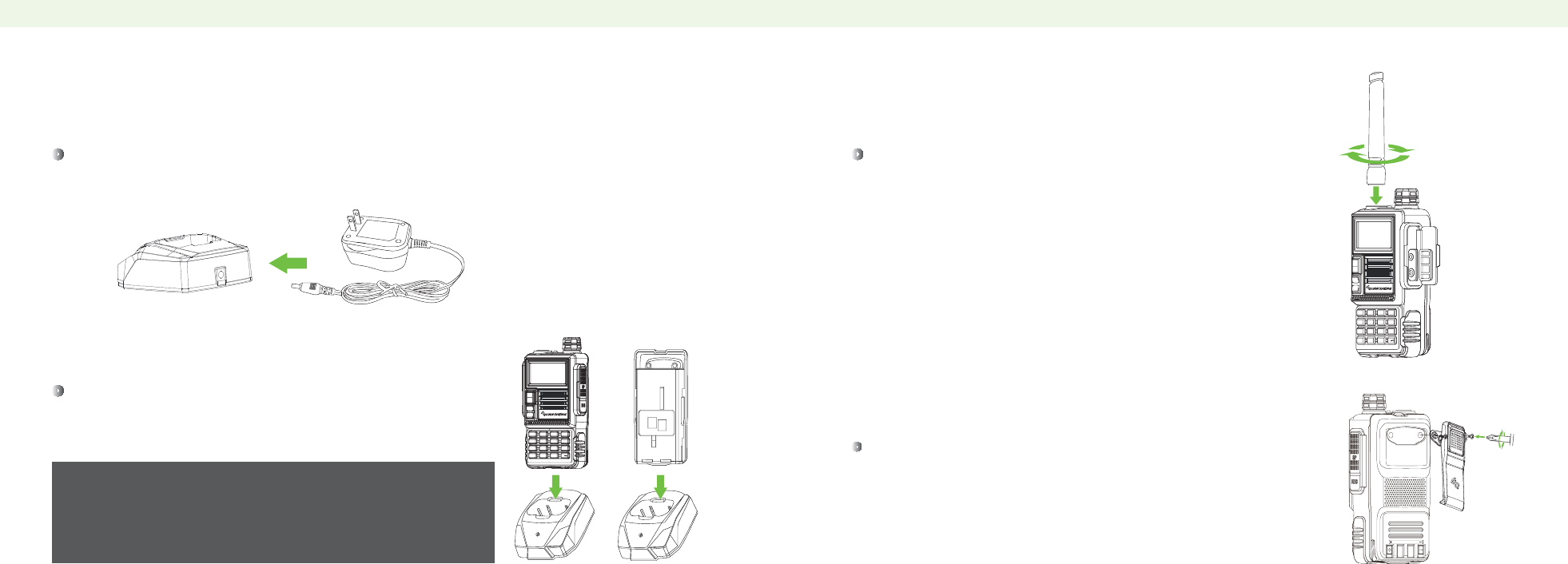
Plug the AC adapter into the back of the charger. Then plug the power cable of the adapter into
city electric power.
Slide the Li-ion battery pack or radio with a Li-ion battery pack
into the charger.
CHARGING NOTES (2)
Attach the antenna to the radio as illustrated on the right.
INSTALLING BELT CLIP
Attach the belt clip with the supplied screws by a phillips screw driver.
INSTALLING ANTENNA
ʎ
ʎ
ʎ
Make sure the battery pack is in connected with the charging
terminals.
When charging begins, the RED LED light displays.
When the battery pack is charged to its greatest capacity, the
GREEN LED light displays. And pls remove the battery or radio
from charger. 03 04
SCAN
MENU EXIT
^
^
1STEP 2TXP 3SAVE
0SQL
6ABR
5WN
7TDR
4VOX
8BEEP 9TOT #
*
BAND
A/B
VFO
MR
MENU EXIT
^
^
1STEP 2TXP 3SAVE
0SQL
6ABR
5WN
7TDR
4VOX
8BEEP 9TOT #
*SCAN
A/B
VFO
MR
BAND

FUNCTION OPERATION AND DESCRIPTION(The following description is without
voice prompt.) FUNCTION OPERATION AND DESCRIPTION(The following description is without
voice prompt.)
ALL-Menu and channel initialization
Manually Lock the Keypads
1. Press key “#” for more than 2s, the radio will be locked and the LCD displays:
2. Press key “#” for more than 2s to unlock.
This function can lock the keypads.
40
RESET
SURE?
1. In frequency or channel mode, press Menu+40, the LCD displays:
2. Press key Menu, and then press key ▲ or ▼ to choose VFO, and then press key Menu
again,the LCD displays:
3. Press key Menu, the LCD displays:
4. Press key Menu to confirm and return to standby automatically.
VFO-Menu initialization
41
RESET
VFO
41
RESET
SOURE?
41
RESET
WATT
RESET
ALL
40
1. In frequency or channel mode, press Menu+40, the LCD displays:
2. Press key Menu, and then press key ▲ or ▼ to choose ALL, and then press key Menu
again,the LCD displays:
3. Press key Menu, the LCD displays:
4. Press key Menu to confirm and return to standby automatically.
RESET
ALL
40
40
RESET
SOURE?
40
RESET
WATT
400.875
136.225
!
NOTE
When listening to the radio, the frequency or channel of A/B receiveing signal will automatically
switch to the frequency or channel state for nornal transimiting and receiving. And it will
automatically switch to FM state when signal disappears.
ʎ
FM Radio(FM)
You can listen to the radio frequency, the frequency range is from 65-108MHz.
1. In frequency or channel mode,tap call key, the LCD displays:
2. Press key ▲ or ▼ to adjust radio frequency manually or input known radio frequency.
Example:100.7MHz Input number 1, 0, 0, 7, 0, 0 directly.
88.9MHz Input number 8, 8, 9, 0, 0 directly.
3. Repeatedly press“*”key can be automatically adjusted to the radio station.
4. Tap call key to exit FM radio.
The operation steps are as follows:
FM
100.700
ALARM
136.275
Rapid Alert(ALARM)
In frequency or channel mode, press CALL key for more than 2s for rapid alarm, the LCD
displays: Press key PTT to cancel.
!
NOTE
Alarm mode see Menu No.32.
ʎ
ALARM
136.275
45 46

Jacklight
This function is suitable for night lighting and warning light.
Tap key MON to turn on night lighting.Operate it again to turn on warning light.
Operate it again to turn it off.
Monitor(MON)
In the same frequency mode, it can monitor signal from the others.
Press MON key for more than 2s to turn it on. Release MON key to turn it off.
Channel/Frequency Mode Conversion(VF0/MR)
Tap VFO/MR key to switch between channel and frequency mode.
TX 1750Hz Call Tone
Press key PTT+BAND to send 1750Hz call tone (This function is for the repeater of European market) .
FUNCTION OPERATION AND DESCRIPTION(The following description is without
voice prompt.)
Cable Clone(COPING)
This function can copy one radio’s information to another one.
1. Connect with the main-radio and sub-radio by cloning cable.
2. Press and hold MON to turn the radio on, the LCD displays: COPING. The red light of main-radio
glitter and the green light of sub-radio glitter
3. When the red and green light do not glitter, the LCD of sub-radio displays:
or r it means it successed in cloning.
The operation steps are as follows:
FUNCTION OPERATION AND DESCRIPTION(The following description is without
voice prompt.)
Reverse Function( R )
When you set different frequencies, tapping“*”key can shift the transmitting and receiving
frequency, the LCD displays:
1. As above picture the receiving frequency of channel A is 420.875MHz, the transmitting frequency
frequency is 425.875MHz.
2. Tap“*”key, the receiving frequency is changed to 425.875MHz, the transmitting frequency
is changed to 400.875MHz, the LCD displays:
The operation steps are as follows:
This function can scan the frequency activity from other radios.
The operation steps are as follows:
!
NOTE
This function is invalid in the same frequency.
ʎ
Frequency Scanning
1. In frequency mode, press key“*” for more than 2s, it will frequency scan according
to setted step frequency.
2. Press key ▲ or ▼ to change the direction of scanning.
3. Press any key to confirm after scanning the signal.
!NOTE
Scanning mode see Menu No.18
ʎ
45UV
WELCOME
400.875
136.225
R
425.875
136.225
R
47 48

FUNCTION OPERATION AND DESCRIPTION(The following description is without
voice prompt.)
Channel Scanning
This function can scan the frequency activity from other radios.
1. In channel mode, press key“*”for more than 2s, it can scan according to the channel you setted.
2. Press key ▲ or ▼ to change the direction of scanning.
3. Press any key to confirm after scanning the signal.
The operation steps are as follows:
!
NOTE
Scanning mode see Menu No.18
ʎ
FUNCTION OPERATION AND DESCRIPTION(The following description is without
voice prompt.)
Search CTCSS/DCS Code
Using this function may search and store the CTCSS/DCS code from other radios when in same frequecy.
Cursor“▲” Conversion(A/B)
Directly taping AB key can move the cursor up and down, you can modify or confirm the
parameters of the frequency and channel where the cursor is.
1. In frequency mode, press Menu+11, the LCD displays:
2. Press key Menu, the LCD displays:
3. Press key “*”, the LCD displays:
4. When other radio transmits, the LCD displays: ,CT ▲glitter means the radio
has entered scanning condition.
5. The CTCSS will in turn and fast move from 67.0-254.1MHz.
6. After searching the CTCSS code, the radio will beep and stop scanning.
7. After setting, press key MR/VFO to confirm and store, otherwise press key PTT or Exit to standby.
Example: CTCSS code scanning; the transmitting frequency is 465.255MHz,CTCSS is 88.5Hz
The operation steps are as follows:
!
NOTE
1. The operation steps of DCS scanning is the same with CTCSS, except that it needs to press
Menu+10 to enter scanning. 2. If CTCSS have not searched the code, you can search DCS mode.
ʎ
Automatic Search FM Radio(FM)
This function can automatically search the FM radio frequency.The frequency range is from
65-108MHz
1. In frequency or channel mode, tap call key, the LCD displays:
2. Repeatedly press “*” key can automatically search the FM radio frequency.
3. Tap call key to exit FM.
The operation steps are as follows:
!
NOTE
When listening to the radio, the frequency or channel of A/B receiving signal will automatically switch to
the frequency or channel state, and when normal transmit and receive signal disappears it will
automatically switch to FM state. Manually search see Menu 42.
ʎ
FM
100.700
R-CTCS 11
OFF
R-CTCS
OFF
11
R-CTCS
OFF
11
R-CTCS
OFF
CT 11
49 50

!
NOTE
Note: You should close PTT-ID code sending when operate function of stun, kill or revive, it’s
better to set the code mixed with ABCD*#.
ʎ
FUNCTION OPERATION AND DESCRIPTION(The following description is without
voice prompt.) FUNCTION OPERATION AND DESCRIPTION(The following description is without
voice prompt.)
32
51 52
Stun/Kill/Revive
This function can remote control other radios in these status: only receive without transmit, receive
and transmit forbidden, activate it back to normal use. Stun: only receive without transmit, Kill: receive
and transmit forbidden, Revive: activate it back to normal use.
1. Please click “Edit” in PC program software, then click “DTMF code”, finally fill custom 5 digit code (Stun/Kill/
Revive) in the parameter frame. There is “ troop call code” in option box and choose code “A” (troop call code
is universal character of ANI code), finally write into radio. (Note: Troop call code can be ABCD*#)
For example: Stun code AB*88 Kill code CD120 Revive code A8A8A
2. The ANI code of sub-radio should be set by computer programming, please write user-defined ANI code in
“ ID CODE”frame after press “Edit” and “DTMF” .(Details please refer to Menu 15 in page 30) Note: The ANI
code of each radio is independent.
For example: 1st sub-radio: 10026 2nd sub-radio: 10088 3rd sub-radio: 10033 4th sub-radio: 222333
3. Open DTMF in menu 33 and confirm it. When DTMF is working, you should choose “QT” or “QT&DT” in menu
34 to realize normal talk. CTCSS and DCS also must stay the same.
4. If you want to remote stun 2nd sub-radio, press PTT key of main-radio and input ANI code of 2nd sub-radio “10088”
and stun code “AB*88” by keypad (Note: 10088AB*88), then the 2nd sub-radio can only receive without transmit.
If you want to recover it in normal working, press PTT key of main-radio and input ANI code of 2nd sub-radio
“10088”and revive code “A8A8A” by keypad (Note: 10088A8A8A), the 2nd sub-radio will return in normal use.
5. If you want to remote stun 1st, 2nd, 3rd sub-radios at the same time, press PTT key of main-radio, then input first
The radio has 19 keypads, including digit 0-9, *, # , function keys and ABCD letter keys. (Details
please refer to digit keypads basic operation in page 11). Implementation step: press PTT to
send both the ANI ID of sub-radio and remote code to realize the function, each code is 5 digits.
Single call/Group call/Troop call
The function can realize single call, group call and troop call in same frequency by DTMF and PTT-ID.
The radio has 19 keypads, including digit 0-9, *, # , function keys and ABCD letter keys. (Details
please refer to digit keypads basic operation in page 11). Implementation step: please send
own ANI code firstly, then send adverse ANI code, you should send two codes to activate
communication, each code is 5 digits.
Operating steps in frequency mode:
Operating steps:
three same digits of ANI code of 3 sub-radio and two digits of troop call “100AA” and stun code “A8A8A” by
keypad (Note: 100AAAB*88), finally the sub-radios can only receive without transmit. If you want to recover them
in normal working, press PTT key of main-radio and input first three same digits of ANI code of 3 sub-radio and two
digits of troop call “100AA” and revive code “A8A8A” (Note: 100AAA8A8A), the sub-radios will return in normal
use.
6. If you want to stun all the sun-radios at the same time, press PTT key of main-radio, then input troop code “AAAAA”
and stun code “AB*88” (Note: AAAAAAB*88), finally all the sub-radios can only receive without transmit. If you want
to recover them in normal working, press PTT key of main-radio, then input troop call of sub-radios “AAAAA” and
revive code “A8A8A” (Note: AAAAAA8A8A), finally all the sub-radios will return in normal use.
7. In order the radio will be stunned or killed randomly, there is a “controlled” in the option box of DTMF in the
software, if you select “√ ”, it mean the radio will be stunned or killed accordingly, if do not select “√ ”, it mean
the radio can not be controlled to entry state of stun or kill.

FUNCTION OPERATION AND DESCRIPTION(The following description is without
voice prompt.) FUNCTION OPERATION AND DESCRIPTION(The following description is without
voice prompt.)
53 54
1. ANI code can be set by PC programming only, you can input user-defined code in “ ID CODE” frame after click
“DTMF” and “Edit” in toolbar. (Details please refer to Menu 15 in page 30) Note: The ANI code of each radio is
independent.
For example: 1st sub-radio: 10026 2nd sub-radio: 10088 3rd sub-radio: 22233 4th sub-radio: 88888
2. Set up parameters in each radio, in Menu 17 (Details in page 31), select one of fifteen groups ( Note: 15 groups
signal code corresponds to DTMF code in software) and confirm it. In Menu 19, open up PTT-ID and notice the
delay time of code sending (Details in page 33), then confirm it. In Menu 33, open up DTMF (Details in page 40)
and confirm it. In Menu 34, set the mute type (details in page 41) and confirm it.
3. Single Call
We only want to call individually even if when all radios are set in the same frequency.
a. If you want to call 1st sub-radio, press and hold the PTT key, the radio will send PTT-ID automatically when
calling, then input the ID code “10026” of 1st sub-radio (Note: 8888810026) , the single call of 1st sub-radio
is successfully activated.
b. If you don’t want to open PTT-ID, press and hold PTT key and input own AI code “88888” and AI code
“10026” of 1st sub-radio (Note: 8888810026), the single call of 1st sub-radio is successfully activated.
c. You should press PTT key of 1st sub-radio to send the confirm message to main radio after the single call is
activated, finally the two radios can work with each other. If the activate time is 5s, it mean you should resend
the code to activate it when the radio standby more than 5s.You can set up the activate time in frame “1-15s
launch overtime warning” in DTMF side tone after clicking “option box” and “Edit” in PC program software.
4. Group Call
For example: set two radios as a group call when many radios are in the same frequency.
a. There is “ troop call code” in option box and choose code “A” (troop call code is universal character of ANI code)
after click “Edit” and “DTMF” in toolbar, finally write it into radio. (Troop call code can be mixed with ABCD*#)
b. When you want to make a group call, press and hold PTT key of main radio to send the own PTT-ID code, then
input the first three same digits of 1st sub-radio and 2nd sub-radio and 2 digit group call code 100AA (Note:
88888100AA) by keypad, the group call of 1st sub-radio and 2nd sub-radio is successfully activated.
c. If you don’t want to open PTT-ID, press and hold PTT key and input own AI code “88888”, then input the first
three same digits of 1st sub-radio and 2nd sub-radio and 2 digit group call code 100AA (Note: 88888100AA) by
keypad, the group call of 1st sub-radio and 2nd sub-radio is successfully activated.
d. You should press PTT key of either 1st sub-radio or 2nd sub-radio to send the confirm message to main radio
after the group call is activated, finally the three radios can work with each other. If the activate time is 5s, it
mean you should resend the code to activate it when the radio standby more than 5s.You can set up the activate
time in frame “1-15s launch overtime warning” in DTMF side tone after clicking “option box” and “Edit” in
PC program software.
5. Troop Call
For example: we can set the troop call when many radios are in the same frequency.
a. There is “ troop call code” in option box and choose code “A” (troop call code is universal character of ANI
code) after click “Edit” and “DTMF” in toolbar, finally write it into radio. (Troop call code can be mixed with
ABCD*#)
b. When you want to make a troop call, press and hold PTT key of main radio to send the own PTT-ID code, then
input the five digits troop call code “AAAAA” (Note: 88888AAAAA), the troop call is successfully activated.
c. If you don’t want to open PTT-ID, press and hold PTT key and input own AI code “88888”, then input the five
digits troop call code “AAAAA” (Note: 88888AAAAA), the troop call is successfully
d. You should press PTT key of any sub-radios to send the confirm message to main radio after the troop call is
activated, finally all the radios can work with each other. If the activate time is 5s, it mean you should resend the
code to activate it when the radio standby more than 5s.You can set up the activate time in frame “1-15s launch

!
NOTE
The function is only valid when
PTT-ID is open.
ʎ
FUNCTION OPERATION AND DESCRIPTION(The following description is without
voice prompt.) FUNCTION OPERATION AND DESCRIPTION(The following description is without
voice prompt.)
55 56
Single call/Group call/Troop call in channel mode
Automatic Control of Single Call/Group call/Troop call
It mean you can activate these function only by selecting the signal code and pressing PTT key, no
need to use sending code.
1. ANI code can be set by PC programming only, you can input user-defined code in “ ID CODE” frame after click
“DTMF” and “Edit” in toolbar. (Details please refer to Menu 15 in page 30) Note: The ANI code of each radio is
independent.
For example: 1st sub-radio: 10026 2nd sub-radio: 10088 3rd sub-radio: 22233 4th sub-radio: 88888
2. There is “ troop call code” in option box and choose code “A” (troop call code is universal character of ANI code),
finally write into radio. (Troop call code can be ABCD*#)
3. Steps to set 15 groups of signal code: please click “Edit” in toolbar and click “DTMF”, then input the AI code of
1st sub-radio, 2nd sub-radio and 3rd sub-radio to the corresponding 1, 2, 3 code group in DTMF frame, then input
group code “100AA” to four groups and input troop code “AAAAA” to the five groups (Note: The signal code
corresponds to DTMF code in PC software is in Menu 17, details please refer to page 31), finally write into the radio
after edit.
Operating steps:
1. If you want to make single call/group call/troop call in channel mode, please select Menu 27 to store channel (details
please refer to page 36) or set all the above parameters in PC programming and write them into radios, corresponding
to the above a, b, c, d to realize function after finish the above A and B operation steps accordingly.
4. Parameters setting: select Menu 19, then open PTT-ID and set the delay time of code sending (Details please refer
to page 33) and confirm it; select Menu 33, then open DTMF (Details please refer to page 40) and confirm it; select
Menu 34 to set the silent mode and select QT+DT (Details please refer to page 41) and confirm it, finally the setting
is finished.
5. If you want to make a single call to 1st sub-radio: in Menu 17 “signal code” (Details please refer to page 31) and
select first group (Note: The signal code corresponds to DTMF code in PC software) and confirm it; press PTT key
of main radio to transmit the own PTT-ID and adverse PTT-ID, the single call is activated successfully. If you want to
call signal code of 2nd sub-radio and 3rd sub-radio please select corresponding second and third group.
6. If you want to make a group call to 1st sub-radio and 2nd sub-radio: in Menu 17 “signal code” (Details please refer
to page 31) and select the fourth group (Note: The signal code corresponds to DTMF code in PC software) and
confirm it; press PTT key of main radio to transmit the own PTT-ID and group call code, the group call is activated
successfully.
7. If you want to make a troop call: in Menu 17 “signal code” (Details please refer to page 31) and select the fifth
group (Note: The signal code corresponds to DTMF code in PC software) and confirm it; press PTT key of main radio
to transmit the own PTT-ID and troop call code, the troop call is activated successfully.
8. You should press PTT key of any sub-radio to send the confirm message to main radio after the single call/group
call/troop call is activated, finally all the radios can work with each other. If the activate time is 5s, it mean you should
resend the code to activate it when the radio standby more than 5s.You can set up the activate time in frame “1-15s
launch overtime warning” in DTMF side tone after clicking “option box” and “Edit” in PC program software.
overtime warning” in DTMF side tone after clicking “option box” and “Edit” in PC program software.
Code Group Sending Code
110026
210088
322233
4100AA
5
AAAAA
6
7
For example:

01
02
03
04
05
06
07
08
09
10
11
12
13
14
15
16
17
D023N
D025N
D026N
D031N
D032N
D036N
D043N
D047N
D051N
D053N
D054N
D065N
D071N
D072N
D073N
D074N
D114N
18
19
20
21
22
23
24
25
26
27
28
29
30
31
32
33
34
D115N
D116N
D122N
D125N
D131N
D132N
D134N
D143N
D145N
D152N
D155N
D156N
D162N
D165N
D172N
D174N
D205N
35
36
37
39
39
40
41
42
43
44
45
46
47
48
49
50
51
D212N
D223N
D225N
D226N
D243N
D244N
D245N
D246N
D251N
D252N
D255N
D261N
D263N
D265N
D266N
D271N
D274N
52
53
54
55
56
57
58
59
60
61
62
63
64
65
66
67
68
D306N
D311N
D315N
D325N
D331N
D332N
D343N
D346N
D351N
D356N
D364N
D365N
D371N
D411N
D412N
D413N
D423N
69
70
71
72
73
74
75
76
77
78
79
80
81
82
83
84
85
D431N
D432N
D445N
D446N
D452N
D454N
D455N
D462N
D464N
D465N
D466N
D503N
D506N
D516N
D523N
D526N
D532N
86
87
88
89
90
91
92
93
94
95
96
97
98
99
100
101
102
D546N
D565N
D606N
D612N
D624N
D627N
D631N
D632N
D654N
D662N
D664N
D703N
D712N
D723N
D731N
D732N
D734N
67.0
69.3
71.9
74.4
77.0
79.7
82.5
85.4
88.5
91.5
94.8
97.4
100.0
103.5
107.2
110.9
114.8
118.8
123.0
127.3
131.8
136.5
141.3
146.2
151.4
156.7
159.8
162.2
165.5
167.9
171.3
173.8
177.3
179.9
183.6
186.2
189.9
192.8
196.6
199.5
203.5
206.5
210.7
218.1
225.7
229.1
233.6
241.8
250.3
254.1
01
02
03
04
05
06
07
08
09
10
21
22
23
24
25
26
27
28
29
30
11
12
13
14
15
16
17
18
19
20
31
32
33
34
35
36
37
39
39
40
41
42
43
44
45
46
47
48
49
50
CTCSS DCS
CTCSS DCS
57 58

D743N
D754N
D023I
D025I
D026I
D031I
D032I
D036I
D043I
D047I
D051I
D053I
D054I
D065I
D071I
D072I
D073I
D074I
121
122
123
124
125
126
127
128
129
130
131
132
133
134
135
136
137
138
D114I
D115I
D116I
D122I
D125I
D131I
D132I
D134I
D143I
D145I
D152
D155I
D156I
D162I
D165I
D172I
D174II
D205I
139
140
141
142
143
144
145
146
147
148
149
150
151
152
153
154
155
156
D212I
D223I
D225I
D226I
D243I
D244I
D245I
D246I
D251I
D2521
D255I
D261I
D263I
D265I
D266I
D271I
D274I
D306I
157
158
159
160
161
162
163
164
165
166
167
168
169
170
171
172
173
174
D311I
D315I
D325I
D331I
D332I
D343I
D346I
D351I
D356I
D364I
D365I
D371I
D411I
D412I
D413I
D4231
D431I
D432I
175
176
177
178
179
180
181
182
183
184
185
186
187
188
189
190
191
192
D445I
D446I
D452I
D454I
D455I
D462I
D464i
D465I
D466I
D503I
D506I
D516I
D523I
D526I
D532I
D546I
D565I
D606I
193
194
195
196
197
198
199
200
201
202
203
204
205
206
207
208
D612I
D624I
D627I
D631I
D632I
D654I
D662I
D664I
D703I
D712I
D723I
D731i
D732I
D734I
D743I
D754I
103
104
105
106
107
108
109
110
111
112
113
114
115
116
117
118
119
120
GENERAL
Rated voltage
VHF:136~174MHz,UHF:400~480MHzFrequency range
Memory channel
Antenna impedance
Working manner
Step frequency
Frequency sensitivity
Working temperature
Battery capacity
Dimensions
DC7.2V(Rechargeable Li-ion battery)
128 channels
50Ω
Same frequency single operation or different frequency single operation
2.5/6.25/10/12.5KHz
±2.5ppm
-20℃~+50℃
2500mAh
122mmX63mmX36mm
TRANSMITTER RECEIVER
Sensitivity -122dBm(12dB SINAD)Output power
Supurious radiation
Adjacent channel selectivity
Emission current
Modulation sensitivity
5W
<7.5μW
≤0.4A
8~12mV
Modulation band
Audio power
Audio distortion
Receive current
Adjacent channel selectivity
Spurious rejection
5KHz
1W
<10%
≤380mA
≥65dB
DCS
SPECIFICATIONS
All stated specifications are subject to change without notice or obligation
ʎ
DCS SPECIFICATIONS
59 60
11KФF3E
2.5KHz
Modulation mode
Maximum frequency deviation
CTCSS/DCS frequency deviation
Signal-noise rate
≤-60dB
0.4KHz±0.1KHz
≥-40dB
Intermodulation
≥60dB
≥60dB

SAFETYTRAININGINFORMATION
Your radiogeneratesRFelectromagnetic
energyduringtransmitmode.Thisradioisdesignedforandclassifiedas“OccupationalUse
Only”,meaningitmustbeusedonlyduringthecourseofemploymentbyindividualsaware
ofthehazards,andthewaystominimizesuchhazards.ThisradioisNOTintendedforuseby
the“GeneralPopulation”inanuncontrolledenvironment.
ThisradiohasbeentestedandcomplieswiththeFCCRFexposurelimitsfor“OccupationalUseOnly”.Inaddition,
your radiocomplieswiththefollowingStandardsandGuidelines
withregardtoRFenergyandelectromagneticenergylevelsandevaluationofsuchlevelsforexposuretohumans:
FCC OET Bulletin 65 Edition 97-01 Supplement C, Evaluating Compliance with FCC Guidelines for Human Exposure to
Radio Frequency Electromagnetic Fields.
American National Standards Institute (C95.1-1992), IEEE Standard for Safety Levels with Respect to Human Exposure
to Radio Frequency Electromagnetic Fields, 3 kHz to 300 GHz.
American National Standards Institute (C95.3-1992), IEEE Recommended Practice for the Measurement of Potentially
Hazardous Electromagnetic Fields– RF and Microwave.
Theinformationlistedaboveprovidestheuserwiththeinformationneededtomakehimor
herawareofRFexposure,andwhattodotoas‐surethatthisradiooperateswiththeFCCRF
exposurelimitsofthisradio.
ElectromagneticInterference/Compatibility
Duringtransmissions,your
radiogeneratesRFenergythatcan
possiblycauseinterferencewithotherdevicesorsystems.Toavoidsuchinterference,turnofftheradioinareas
wheresignsarepostedtodoso.DONOToperatethetransmitterinareasthataresensitivetoelectromagnetic
radiationsuchashospitals,aircraft,andblastingsites.
Occupational/ControlledUse
Theradiotransmitterisusedinsituationsinwhichpersonsareexposedasconsequenceoftheiremployment
providedthosepersonsarefullyawareofthepotentialforexposureandcanexercisecontrolovertheirexposure.
Attention:
This radio complieswith IEEE and ICNIRP exposure limits for occupational/controlled RF exposure emvironment
at operating duty factors of up to 50% and is authorized by the FCC for occupational use only. An appropriate warning
lable is affixed to all units. In order to comply with RF exposure requirements, a minimum distance of 2.5cm must be
maintained when held-to-face, and body-worn operations are restricted to the approved original acessories (belt clip).
Do not use this device when antenna shows obvious damages
Fujian Nanan Quansheng Electronics Co.,Ltd.
Fujian Nanan Quansheng Electronics Co.,Ltd.
Fujian Nanan Quansheng Electronics Co.,Ltd.
Only the headset reported in test report can be used.